WO2009104296A1 - Module de culture cellulaire - Google Patents
Module de culture cellulaire Download PDFInfo
- Publication number
- WO2009104296A1 WO2009104296A1 PCT/JP2008/067703 JP2008067703W WO2009104296A1 WO 2009104296 A1 WO2009104296 A1 WO 2009104296A1 JP 2008067703 W JP2008067703 W JP 2008067703W WO 2009104296 A1 WO2009104296 A1 WO 2009104296A1
- Authority
- WO
- WIPO (PCT)
- Prior art keywords
- cell culture
- internal space
- culture
- cell
- water pressure
- Prior art date
- Legal status (The legal status is an assumption and is not a legal conclusion. Google has not performed a legal analysis and makes no representation as to the accuracy of the status listed.)
- Ceased
Links
Images




Classifications
-
- C—CHEMISTRY; METALLURGY
- C12—BIOCHEMISTRY; BEER; SPIRITS; WINE; VINEGAR; MICROBIOLOGY; ENZYMOLOGY; MUTATION OR GENETIC ENGINEERING
- C12M—APPARATUS FOR ENZYMOLOGY OR MICROBIOLOGY; APPARATUS FOR CULTURING MICROORGANISMS FOR PRODUCING BIOMASS, FOR GROWING CELLS OR FOR OBTAINING FERMENTATION OR METABOLIC PRODUCTS, i.e. BIOREACTORS OR FERMENTERS
- C12M33/00—Means for introduction, transport, positioning, extraction, harvesting, peeling or sampling of biological material in or from the apparatus
- C12M33/12—Means for introduction, transport, positioning, extraction, harvesting, peeling or sampling of biological material in or from the apparatus by pressure
-
- C—CHEMISTRY; METALLURGY
- C12—BIOCHEMISTRY; BEER; SPIRITS; WINE; VINEGAR; MICROBIOLOGY; ENZYMOLOGY; MUTATION OR GENETIC ENGINEERING
- C12M—APPARATUS FOR ENZYMOLOGY OR MICROBIOLOGY; APPARATUS FOR CULTURING MICROORGANISMS FOR PRODUCING BIOMASS, FOR GROWING CELLS OR FOR OBTAINING FERMENTATION OR METABOLIC PRODUCTS, i.e. BIOREACTORS OR FERMENTERS
- C12M23/00—Constructional details, e.g. recesses, hinges
- C12M23/34—Internal compartments or partitions
-
- C—CHEMISTRY; METALLURGY
- C12—BIOCHEMISTRY; BEER; SPIRITS; WINE; VINEGAR; MICROBIOLOGY; ENZYMOLOGY; MUTATION OR GENETIC ENGINEERING
- C12M—APPARATUS FOR ENZYMOLOGY OR MICROBIOLOGY; APPARATUS FOR CULTURING MICROORGANISMS FOR PRODUCING BIOMASS, FOR GROWING CELLS OR FOR OBTAINING FERMENTATION OR METABOLIC PRODUCTS, i.e. BIOREACTORS OR FERMENTERS
- C12M25/00—Means for supporting, enclosing or fixing the microorganisms, e.g. immunocoatings
- C12M25/02—Membranes; Filters
-
- C—CHEMISTRY; METALLURGY
- C12—BIOCHEMISTRY; BEER; SPIRITS; WINE; VINEGAR; MICROBIOLOGY; ENZYMOLOGY; MUTATION OR GENETIC ENGINEERING
- C12M—APPARATUS FOR ENZYMOLOGY OR MICROBIOLOGY; APPARATUS FOR CULTURING MICROORGANISMS FOR PRODUCING BIOMASS, FOR GROWING CELLS OR FOR OBTAINING FERMENTATION OR METABOLIC PRODUCTS, i.e. BIOREACTORS OR FERMENTERS
- C12M29/00—Means for introduction, extraction or recirculation of materials, e.g. pumps
- C12M29/14—Pressurized fluid
-
- C—CHEMISTRY; METALLURGY
- C12—BIOCHEMISTRY; BEER; SPIRITS; WINE; VINEGAR; MICROBIOLOGY; ENZYMOLOGY; MUTATION OR GENETIC ENGINEERING
- C12M—APPARATUS FOR ENZYMOLOGY OR MICROBIOLOGY; APPARATUS FOR CULTURING MICROORGANISMS FOR PRODUCING BIOMASS, FOR GROWING CELLS OR FOR OBTAINING FERMENTATION OR METABOLIC PRODUCTS, i.e. BIOREACTORS OR FERMENTERS
- C12M41/00—Means for regulation, monitoring, measurement or control, e.g. flow regulation
- C12M41/40—Means for regulation, monitoring, measurement or control, e.g. flow regulation of pressure
-
- C—CHEMISTRY; METALLURGY
- C12—BIOCHEMISTRY; BEER; SPIRITS; WINE; VINEGAR; MICROBIOLOGY; ENZYMOLOGY; MUTATION OR GENETIC ENGINEERING
- C12M—APPARATUS FOR ENZYMOLOGY OR MICROBIOLOGY; APPARATUS FOR CULTURING MICROORGANISMS FOR PRODUCING BIOMASS, FOR GROWING CELLS OR FOR OBTAINING FERMENTATION OR METABOLIC PRODUCTS, i.e. BIOREACTORS OR FERMENTERS
- C12M47/00—Means for after-treatment of the produced biomass or of the fermentation or metabolic products, e.g. storage of biomass
Definitions
- the present invention relates to a cell culture module.
- a cell culture device that includes a culture container that stores a culture solution containing a cell culture carrier and cells, and a magnetic field generator that generates a magnetic field for moving the cell culture carrier in the culture solution (for example, Patent Document 2).
- JP 2005-27598 A Japanese Patent Laid-Open No. 2004-313007
- the cell culture techniques as shown in Patent Documents 1 and 2 described above require peeling work from the cell culture chip and the cell culture carrier after cells are cultured. This peeling operation is usually performed using an enzyme treatment such as trypsin treatment. However, when such an enzyme treatment is carried out for a long time, the cultured cells deteriorate to some extent, and in the worst case, the cells themselves may die. In addition, enzyme treatment such as trypsin treatment has a problem that the operation is very complicated. Accordingly, the present invention has been made in view of the above-described problems, and a cell that can be easily detached from a cell culture carrier without culturing an enzyme treatment such as trypsin treatment. An object is to provide a culture module.
- the cell culture module includes a sealed system member that holds a cell culture support comprising a porous body provided with a recess for culturing cells in an internal space so that the internal space can be sealed, and the internal space is filled with a culture solution Then, a water pressure supply unit that supplies water pressure to the second surface that faces the first surface of the cell culture carrier that is held in the internal space is provided with the concave portion, and the water pressure on the second surface from the concave portion. And a cell collection unit for collecting the detached cells from the internal space. With such a configuration, cells cultured on a cell culture carrier can be easily detached from the cell culture carrier without performing an enzyme treatment such as trypsin treatment.
- the cell culture module according to the present invention includes a closed system member that holds a cell culture support comprising a porous body provided with a recess for culturing cells in an internal space so that the internal space can be sealed, and the internal space is filled with a culture solution.
- a water pressure supply unit for supplying water pressure to the second surface facing the first surface provided with the concave portion and the concave portion of the cell culture carrier held in the internal space, and with respect to the second surface
- a cell recovery unit for recovering cells detached from the recess by water pressure from the internal space.
- the cell culture module according to the present invention includes a closed system member that holds a cell culture support made of a porous body provided with a concave portion for culturing cells in an internal space so that the internal space can be sealed, and the internal space is filled with a culture solution. Circulates the filled culture solution and supplies water pressure to the concave portion of the cell culture carrier held in the internal space by the circulation and the second surface facing the first surface provided with the concave portion. And a cell recovery unit for recovering from the internal space cells detached from the recess by water pressure on the second surface.
- cells resistant to pressure such as chondrocytes can be cultured, and cells cultured on a cell culture carrier without performing enzyme treatment such as trypsin treatment can be used. Can be easily peeled off.
- the cell culture module according to the present invention includes a closed system member that holds a cell culture support made of a porous body provided with a concave portion for culturing cells in an internal space so that the internal space can be sealed, and the internal space is filled with a culture solution.
- a water pressure supply unit that supplies water pressure to the second surface opposite to the first surface provided with the recess of the cell culture carrier held in the internal space, and the water pressure with respect to the second surface
- a cell recovery unit for recovering cells detached from the recess from the internal space.
- the apparatus further includes a second water pressure supply unit that supplies water pressure from the horizontal direction of the cell culture carrier held in the internal space.
- a second water pressure supply unit that supplies water pressure from the horizontal direction of the cell culture carrier held in the internal space.
- the pores of the porous body constituting the cell culture carrier have an average pore diameter of 10 nm or more and 10 ⁇ m or less, and the pores are provided in communication from the surface of the recess of the cell culture carrier to the second surface. Is preferred. With this configuration, the water pressure supplied to the second surface of the cell culture carrier can be transmitted to the surface of the concave portion of the cell culture carrier. It can be easily detached from the culture carrier.
- the present invention provides a cell culture module that allows cells cultured on a cell culture carrier to be easily detached from the cell culture carrier without performing an enzyme treatment such as trypsin treatment.
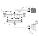
- FIG. 1 is a conceptual diagram showing a cross-sectional configuration of the cell culture module according to the first embodiment.
- the cell culture module 1 according to the present embodiment includes a closed system member 10, a culture fluid water pressure supply unit 20, and a cell recovery unit 30.
- the sealing system member 10 includes a lower lid 10A, an upper lid 10B provided on the lower lid 10A, and a fixing member 15 that fixes the lower lid 10A and the upper lid 10B. ing.
- the lower lid 10 ⁇ / b> A is configured to have a concave shape including a concave portion 10 ⁇ / b> Aa for holding the cell culture carrier S and accommodating the culture solution.
- the upper lid 10B is provided on the lower lid 10A, forms an inner space 12 with the lower lid 10A, and a recess 10Aa of the lower lid 10A in order to hold the inner space 12 in a sealable manner. Is provided with a convex portion 10Ba that can be sealed.
- the cell culture carrier S is held by placing an O-ring 17a on the bottom 10Aa1 of the recess 10Aa of the lower lid 10A and placing the cell culture carrier S on the O-ring 17a.
- the O-ring 17b is arranged on the culture carrier S, and the lower lid 10A and the upper lid 10B are fixed integrally with the O-ring 17a, the cell culture carrier S and the O-ring 17b, the convex portion 10Ba of the upper lid 10B.
- the cell culture carrier S is held in the recess 10Aa of the lower lid 10A by pressurizing the O-ring 17b.
- the lower lid 10A and the upper lid 10B are made of, for example, acrylic resin.
- the fixing member 15 is made of, for example, SUS304.
- the O-rings 17a, 17b, and 17c are made of, for example, fluorine rubber.
- the closed system member 10 is described as having a configuration in which the lower lid 10A and the upper lid 10B are integrally fixed by the fixing member 15 as described above.
- the carrier S is not limited to the above-described configuration as long as the carrier S can be sealed in the internal space 12.
- the cell culture carrier S that is hermetically held in the internal space 12 is composed of a porous body provided with a recess S1 for culturing cells on the surface (first surface) Sa.
- the cell culture carrier S is composed of at least one ceramic or glass of zirconia, yttria, titania, alumina, silica, hydroxyapatite, and ⁇ -tricalcium phosphate. These ceramics or glass are suitable because of high biostability.
- the culture fluid water pressure supply unit 20 is provided integrally or detachably on the bottom 10 ⁇ / b> Aa ⁇ b> 1 of the lower lid 10 ⁇ / b> A and supplies the culture fluid to the internal space 12.
- the culture fluid hydraulic pressure supply unit 20 includes a culture fluid storage portion 22 that stores a culture fluid, one end attached to the bottom 10 ⁇ / b> Aa ⁇ b> 1, and the other end attached to the storage portion 22.
- the culture solution storage unit 22 is composed of, for example, a resin storage container.
- the culture solution supply tube 24 is configured by, for example, a resin tube.
- the supply amount control unit 26 includes, for example, an electromagnetic valve that controls the supply amount of the culture solution. The opening / closing operation and the opening / closing amount of the electromagnetic valve are controlled by a control unit (not shown), and the supply amount of the culture solution is controlled by the opening / closing amount.
- the supply pressure control unit 28 includes, for example, a high-pressure gas supply device that supplies high-pressure gas from the culture solution storage unit 22 to the culture solution supply pipe 24.
- the culture fluid water pressure supply unit 20 is provided on the back surface side Sb of the cell culture carrier S held in the internal space 12 (a surface facing the surface (first surface) Sa provided with the recess S1 of the cell culture carrier S (Water pressure is supplied to the second surface Sb by applying hydraulic pressure in the direction of the second surface)).
- the method for applying the water pressure is to control the supply amount control unit 26 and the supply pressure control unit 28 so as to supply the culture solution to the internal space 12 in a state where the sealed internal space 12 is filled with the culture solution. Do. In other words, with the internal space 12 filled with the culture solution, the supply amount control unit 26 is opened, and the supply pressure control unit 28 increases the supply pressure of the culture solution, thereby increasing the water pressure and reducing the supply pressure. Thus, a small water pressure is supplied to the second surface Sb of the cell culture carrier S.
- the cells cultured in the recess S1 of the cell culture carrier S are peeled off from the cell culture carrier S and put into the culture solution filled in the internal space 12. Float.
- the cell culture carrier S is composed of a porous body (porous body). It is necessary to be.
- the pores of the porous body constituting the cell culture carrier S have an average pore diameter of 10 nm or more and 10 ⁇ m or less, and the pores extend from the surface of the recess S1 of the cell culture carrier S to the second surface Sb. It is preferable to be provided in communication. With such a configuration, the water pressure supplied to the second surface Sb of the cell culture support S can be transmitted to the surface of the recess S1 of the cell culture support S. The cultured cells can be easily detached from the cell culture carrier S.
- the cell recovery unit 30 is provided integrally or detachably on the upper portion 10Ba1 of the upper lid 10B, and is cultured in the concave portion S1 of the cell culture carrier S, and is supplied to the second surface Sb of the cell culture carrier S by the water pressure.
- the cells detached from S are collected from the internal space 12 of the closed system member 10 together with the culture solution.
- the cell recovery unit 30 includes a cell storage unit 32 that stores cultured cells together with a culture solution, one end attached to the upper portion 10Ba1, and the other end attached to the storage unit 32.
- the cell accommodating part 32 is comprised by the resin-type accommodation container, for example.
- the cell discharge tube 34 is composed of, for example, a resin tube.
- the discharge amount control unit 36 is configured by, for example, an electromagnetic valve that controls the discharge amount.
- the opening / closing operation and opening / closing amount of the solenoid valve are controlled by a control unit (not shown), and the discharge amount is controlled by the opening / closing amount.
- FIGS. 2 and 3 are conceptual diagrams for explaining an example of a cell culture method using the cell culture module according to the present embodiment.
- feeder cells Feeder cells
- FIGS. 2 and 3 are conceptual diagrams for explaining an example of a cell culture method using the cell culture module according to the present embodiment.
- a concave lower lid 10A is prepared, and a cell culture carrier S in which an O-ring 17a, feeder cells (Feeder cells) are installed, and an O-ring 17b are laminated in this order on the bottom 10Aa1 of the lower lid 10A.
- a cell culture carrier S in which an O-ring 17a, feeder cells (Feeder cells) are installed, and an O-ring 17b are laminated in this order on the bottom 10Aa1 of the lower lid 10A.
- the cells to be cultured are placed in the recess S1 of the cell culture carrier S placed in the recess 10Aa of the lower lid 10A.
- the installed cell is attached and held on the surface of the cell culture support S.
- the O-ring 17c is inserted into the recess of the convex portion 10Ba of the upper lid 10B, and the concave portion 10Aa of the lower lid 10A and the convex portion 10Ba of the upper lid 10B are fitted to each other, and the lower lid 10A is fixed by the fixing member 15.
- the upper lid 10B are integrally fixed to form the sealed system member 10 according to the present embodiment in which the internal space 12 is formed.
- the culture liquid supply pipe 24 of the culture liquid hydraulic pressure supply unit 20 is attached to the bottom 10Aa1 of the lower lid 10A, and the cell discharge pipe 34 of the cell recovery unit 30 is attached to the upper part 10Ba1 of the upper lid 10B.
- the cell culture module 1 is configured.
- the discharge amount control unit 36 of the cell recovery unit 30 is set to the “open” state (in this embodiment, the electromagnetic valve of the discharge amount control unit 36 is set to the “open” state), and the supply amount control of the culture fluid water pressure supply unit 20 is performed.
- the unit 26 is set to the “open” state (in this embodiment, the solenoid valve of the supply amount control unit 26 is set to the “open” state), and further, the supply pressure is supplied from the supply pressure control unit 28 to culture in the internal space 12.
- the culture solution is supplied from the culture solution storage unit 22 until the solution is completely filled.
- the supply pressure from the supply pressure control unit 28 is stopped, and the supply amount control unit 26 is set to the “closed” state (in this embodiment, the electromagnetic amount of the supply amount control unit 26).
- the discharge amount control unit 36 of the cell recovery unit 30 is set to the “closed” state (in this embodiment, the electromagnetic valve of the discharge amount control unit 36 is set to the “closed” state).
- the discharge amount control unit 36 of the cell recovery unit 30 is set to the “open” state to start the discharge of the culture solution in the internal space 12 and the supply amount control unit 26 of the culture solution water pressure supply unit 20 is “open”.
- a supply pressure is supplied from the supply pressure control unit 28 to start supplying a new culture solution to the internal space 12.
- the fluid pressure P 1 is supplied from the culture fluid water pressure supply unit 20 in the direction of the second surface Sb of the cell culture carrier S. Since the hydraulic pressure P 1 supplies water pressure to the second surface Sb of the cell culture carrier S, the cells cultured in the concave portion S1 of the cell culture carrier S are detached from the surface of the concave portion S1 of the cell culture carrier S. Then, it floats in the culture solution in the internal space 12 and is recovered as it is together with the culture solution into the cell storage unit 32 through the cell discharge pipe 34 of the cell recovery unit 30 (FIG. 3).
- the cell culture module according to the present embodiment since the cell culture module according to the present embodiment has the above-described configuration, cells cultured on the cell culture carrier can be easily removed from the cell culture carrier without performing enzyme treatment such as trypsin treatment. Can be peeled off.
- recovery part 30 demonstrated by this embodiment demonstrated in FIG. 1 by the structure provided in upper part 10Ba1 of the upper cover 10B, ie, the upper direction (vertical direction) of the recessed part S1 of the cell culture support S The present invention is not limited to this. For example, as shown in FIG. 4, a horizontal direction perpendicular to the vertical direction of the cell culture carrier S held in the recess 10Aa of the lower lid 10A (in FIG.
- the cell discharge pipe 34 of the cell recovery unit 30 may be installed in the direction of the paper surface.
- the control units 26 and 36 have been described as examples using electromagnetic valves. However, the control units 26 and 36 may be controlled by, for example, a cylinder or a simple manual valve.
- FIG. 5 is a conceptual diagram showing a cross-sectional configuration of the cell culture module according to the second embodiment.
- the culture fluid / water pressure supply unit 20 shown in FIG. 1 described in the first embodiment is arranged in the horizontal direction of the cell culture carrier S (the paper surface direction in FIG. 5). 1 in that an air pressure supply unit 40 is provided at the position of the culture fluid water pressure supply unit 20 shown in FIG. Since others are the same as that of 1st Embodiment, description is abbreviate
- the air pressure supply unit 40 is provided integrally or detachably on the bottom portion 10Aa1 of the lower lid 10A, and supplies air pressure to the culture solution filled in the internal space 12, so that the second surface Sb of the cell culture carrier S is supplied. Supply water pressure.
- the air pressure supply unit 40 is, for example, provided integrally or detachably on the air pressure generating device 42 for generating air pressure and the bottom portion 10Aa1 of the lower lid 10A, and the air pressure generated by the air pressure generating device 42 is the internal space 12.
- an air pressure supply pipe 44 for supplying to the air.
- the air pressure generating device 42 is constituted by an air cylinder, for example.
- the air pressure supply pipe 44 is made of, for example, a resin tube.
- FIG. 6 is a conceptual diagram for explaining an example of a cell culture method using the cell culture module according to the present embodiment.
- the closed system member 10 according to the present embodiment is configured. After that, the air pressure supply pipe 44 of the air pressure supply section 40 is attached to the bottom 10Aa1 of the lower lid 10A, the culture medium supply pipe 24 of the culture liquid pressure supply section 20 is attached in the horizontal direction of the cell culture carrier S, and the upper part of the upper lid 10B.
- the cell culture module 2 according to this embodiment is configured by attaching the cell discharge pipe 34 of the cell recovery unit 30 to 10Ba1.
- the discharge amount control unit 36 of the cell recovery unit 30 is set to the “open” state
- the supply amount control unit 26 of the culture fluid water pressure supply unit 20 is set to the “open” state
- the supply pressure is further supplied from the supply pressure control unit 28.
- the culture solution is supplied from the culture solution storage unit 22 until the culture solution is completely filled in the internal space 12.
- the supply pressure is stopped from the supply pressure control unit 28 and the supply amount control unit 26 is set to the “closed” state, and at the same time, the discharge amount control unit of the cell recovery unit 30 36 is set to the “closed” state.
- the environment in which the cells held in the recess S1 of the cell culture carrier S are cultured is prepared.
- the air pressure P 2 is supplied from the air pressure generator 42 to the culture solution filled in the second surface Sb direction of the cell culture carrier S held in the internal space 12. Thereby, water pressure is supplied to the second surface Sb of the cell culture carrier S. Due to this water pressure, the cells cultured in the recess S1 of the cell culture carrier S are detached from the cell culture carrier S and float in the culture medium in the internal space 12 (FIG. 6).
- the supply amount control unit 26 of the culture solution water pressure supply unit 20 is set to the “open” state, and supply of the culture solution to the internal space 12 is newly started by applying supply pressure from the supply pressure control unit 28, and the cells
- discharge of the culture medium in the internal space 12 is started by setting the discharge amount control unit 36 of the recovery unit 30 to the “open” state, the cultured cells suspended in the internal space 12 together with the culture medium are cell recovery unit 30.
- the cells are collected in the cell storage section 32 through the cell discharge pipe 34.
- the culture fluid hydraulic pressure supply unit 20 is arranged in the horizontal direction of the cell culture carrier S and supplies the culture fluid to the internal space 12 from the horizontal direction.
- a liquid pressure may be applied to the internal space 12 and the water pressure may be supplied from the horizontal direction. Since the method of applying the hydraulic pressure is the same as that described in the first embodiment, the description thereof is omitted. In this way, by applying a water pressure to the internal space 12 from the horizontal direction, the flow of the culture solution in the internal space 12 can be controlled, so that perfusion culture is also possible.
- FIG. 7 is a conceptual diagram showing a cross-sectional configuration of the cell culture module according to the third embodiment.
- the cell culture module 3 according to the present embodiment is a second culture solution that newly supplies a culture solution to the internal space 12 to the upper portion 10Ba1 of the cell culture module shown in FIG. 4 described in the first embodiment.
- the difference is that the water pressure supply unit 50 is provided. Since others are the same as that of 1st Embodiment, description is abbreviate
- the second culture fluid water pressure supply unit 50 is provided integrally or detachably on the upper portion 10Ba1 of the upper lid 10B, and supplies the culture fluid to the internal space 12.
- the second culture fluid hydraulic pressure supply unit 50 includes a culture solution storage unit 52 that stores a culture solution, one end attached to the upper portion 10Ba1 and the other end attached to the storage unit 52.
- a culture solution supply pipe 54 for supplying the culture solution contained in the unit 52 to the internal space 12, and a supply amount control unit 56 for controlling the supply amount of the culture solution attached to the supply tube 54 and supplied to the internal space 12.
- a supply pressure control unit 58 that is attached to the storage unit 52 and controls the supply pressure when the culture solution is supplied.
- the culture solution storage unit 52 is formed of, for example, a resin storage container.
- the culture solution supply pipe 54 is constituted by, for example, a resin tube.
- the supply amount control unit 56 includes, for example, an electromagnetic valve that controls the supply amount of the culture solution.
- the solenoid valve is controlled in its opening / closing operation and opening / closing amount by a control unit (not shown), and the supply amount of the culture solution is controlled by the opening / closing amount.
- the supply pressure control unit 58 is cultivated from the culture solution storage unit 52.
- the high-pressure gas supply device supplies high-pressure gas to the liquid supply pipe 54.
- the second culture fluid / water pressure supply unit 50 supplies water pressure to the recess S ⁇ b> 1 by applying a fluid pressure in the direction of the recess S ⁇ b> 1 of the cell culture carrier S held in the internal space 12.
- the method for applying the water pressure is to control the supply amount control unit 56 and the supply pressure control unit 58 so as to supply the culture solution to the internal space 12 in a state where the sealed internal space 12 is filled with the culture solution. Do. That is, in a state in which the culture solution is filled in the internal space 12, the supply amount control unit 56 is set to the “open” state, and the supply pressure of the culture solution is increased by the supply pressure control unit 58, so that a large water pressure is supplied.
- a small water pressure is supplied to the recess S1 of the cell culture carrier S.
- cells are cultured in the recess S1 while applying a fluid pressure in the direction of the recess S1 of the cell culture carrier S by the second culture fluid water supply unit 50, cells resistant to pressure such as chondrocytes can be cultured.
- FIGS. 8 to 10 are conceptual diagrams for explaining an example of a cell culture method using the cell culture module 3 according to the present embodiment.
- description of the part which overlaps with the part demonstrated in 1st Embodiment is abbreviate
- the cell culture module 3 according to the present embodiment is configured.
- the discharge amount control unit 36 of the cell recovery unit 30 is set to the “open” state
- the supply amount control unit 26 of the culture fluid water pressure supply unit 20 is set to the “open” state
- the supply pressure is further supplied from the supply pressure control unit 28.
- the culture solution is supplied until the culture solution is completely filled in the internal space 12.
- the culture medium may be supplied by controlling the supply amount control unit 56 and the supply pressure control unit 58 in the second culture solution water pressure supply unit 50 as well.
- the culture solution may be supplied only by the second culture solution water pressure supply unit 50.
- the supply pressure from the supply pressure control unit 28 is stopped, the supply amount control unit 26 is set to the “closed” state, and the culture solution in the culture solution water pressure supply unit 20 is supplied. Stop supplying. At this time, similarly, the discharge amount control unit 36 of the cell collection unit 30 is also in the “closed” state (FIG. 8).
- the supply amount control unit 56 of the second culture fluid water pressure supply unit 50 is set to the “open” state, the supply pressure is applied from the supply pressure control unit 58, and the fluid pressure P 3 is set in the direction of the recess S 1 of the cell culture carrier S.
- the cells are cultured while feeding (FIG. 9).
- the supply pressure from the supply pressure control unit 58 is stopped, the supply amount control unit 56 is set to the “closed” state, and the supply of the hydraulic pressure P 3 in the direction of the recess S1 of the cell culture carrier S is stopped.
- the discharge amount control unit 36 of the cell recovery unit 30 is set to the “open” state, and the discharge of the culture medium in the internal space 12 is started, and the supply amount control unit 26 of the culture solution hydraulic pressure supply unit 20 is set to the “open” state. Then, supply pressure is supplied from the supply pressure control unit 28 and supply of the culture medium to the internal space 12 is newly started.
- the fluid pressure P 1 is supplied from the culture fluid water pressure supply unit 20 in the direction of the second surface Sb of the cell culture carrier S. Since the hydraulic pressure P 1 supplies water pressure to the second surface Sb of the cell culture carrier S, the cells cultured in the concave portion S1 of the cell culture carrier S are separated from the surface of the concave portion S1 of the cell culture carrier S. It is peeled off, floats in the culture solution in the internal space 12, and is recovered as it is together with the culture solution into the cell storage unit 32 through the cell discharge pipe 34 of the cell recovery unit 30 (FIG. 10).
- the cell culture module according to the present embodiment has the above-described configuration, cells that are resistant to pressure such as chondrocytes can be cultured, and enzyme treatment such as trypsin treatment can be performed.
- the cells cultured on the cell culture carrier can be easily detached from the cell culture carrier.
- the air pressure can be supplied to the concave portion S1 of the cell culture carrier S by supplying air pressure to the culture solution filled in the internal space 12 by the air pressure supply unit 40, this embodiment has been described. An effect similar to the effect can be obtained.
- FIG. 11 is a conceptual diagram showing a cross-sectional configuration of the cell culture module according to the fourth embodiment.
- the culture fluid / water pressure supply unit 20 and the second culture fluid / water pressure supply unit 50 shown in FIG. 7 described in the third embodiment have the air pressure described in the second embodiment.
- each is replaced with a supply unit 40 and a culture fluid pressure supply unit 20 is newly provided in a direction opposite to the cell recovery unit 30 provided in the horizontal direction of the cell culture carrier S. Since others are the same as that of 3rd Embodiment, description is abbreviate
- the air pressure supply unit 40 attached to the bottom 10Aa1 of the lower lid 10A has the same configuration and operation as those of the second embodiment described above, description thereof is omitted. Also, the air pressure supply unit 40 attached to the upper portion Ba1 of the upper lid 10B has the same configuration and operation as those of the above-described third embodiment, and thus description thereof is omitted.
- the cell culture module 4 according to the present embodiment is configured.
- the discharge amount control unit 36 of the cell recovery unit 30 is set to the “open” state
- the supply amount control unit 26 of the culture fluid water pressure supply unit 20 is set to the “open” state
- the supply pressure is supplied from the supply pressure control unit 28.
- the culture solution is supplied from the culture solution storage unit 22 until the culture solution is completely filled in the internal space 12.
- the supply pressure from the supply pressure control unit 28 is stopped and the supply amount control of the discharge amount control unit 36 of the cell recovery unit 30 and the culture solution water pressure supply unit 20.
- the unit 26 is set to the “closed” state.
- the culture is performed while supplying water pressure onto the recess S1 of the cell culture carrier S by the air pressure supply unit 40 attached to the upper part Ba1 of the upper lid 10B.
- cells resistant to pressure such as chondrocytes can be cultured.
- fluid pressure may be applied in the horizontal direction of the cell culture carrier S from the culture fluid water pressure supply unit 20 into the internal space 12. With such a configuration, the flow of the culture solution in the internal space 12 can be controlled, and perfusion culture is also possible.
- water pressure is supplied to the second surface Sb of the cell culture carrier S by the air pressure supply unit 40 attached to the bottom 10Aa1 of the lower lid 10A, so that the cells cultured in the recess S1 of the cell culture carrier S It is peeled off from the culture carrier S and suspended in the culture medium in the internal space 12.
- the supply amount control unit 26 of the culture solution supply unit 20 is set to the “open” state, the supply pressure is supplied from the supply pressure control unit 28, and the supply of the culture solution to the internal space 12 is newly started.
- the discharge amount control unit 36 When the discharge amount control unit 36 is set to the “open” state and the discharge of the culture solution in the internal space 12 is started, the cultured cells floating in the internal space 12 are transferred to the cells of the cell recovery unit 30 together with the culture solution. It is collected in the cell accommodating part 32 through the discharge pipe 34.
- the cell culture module according to the present embodiment has the above-described configuration, cells that are resistant to pressure such as chondrocytes can be cultured, and enzyme treatment such as trypsin treatment can be performed.
- the cells cultured on the cell culture carrier can be easily detached from the cell culture carrier.
- the culture fluid water pressure supply unit 20 is provided in a direction opposite to the cell recovery unit 30 provided in the horizontal direction of the cell culture carrier S, the speed of recovering the cultured cells to the cell recovery unit 32 is improved. It also has the effect.
- FIG. 12 is a conceptual diagram showing a cross-sectional configuration of the cell culture module according to the fifth embodiment.
- the cell culture module 5 according to the present embodiment is replaced with the culture fluid / water pressure supply unit 20 shown in FIG. 4 described in the first embodiment, and a culture fluid circulation system 100 that circulates the culture fluid in the internal space 12 is newly provided. Different points are provided. Since others are the same as that of 1st Embodiment, description is abbreviate
- the culture medium circulation system 100 includes a circulation unit 110 that circulates the culture solution filled in the internal space 12, and a variable unit that varies the circulation direction (Dn or Up) of the circulation unit 110. 120.
- the circulation unit 110 holds the culture solution in advance and also supplies the culture solution storage unit 112 that temporarily stores the circulated culture solution and the culture solution stored in the storage unit 112 into the internal space 12.
- ON / OFF of circulation of the circulation unit 110 attached to the supply device 114, the pipes 116a, 116b, and 116c, and the pipes 116a and 116c that connect the sealing system member 10, the housing portion 112, and the supply device 114.
- circulation amount control units 118a and 118b for controlling the circulation amount.
- the variable section 120 includes an air pressure generator 122 that supplies air pressure to the pipe 116 a of the circulation section 110, and a pipe 124 that has one end integrally or detachably connected to the pipe 116 a and the other end connected to the generator 122. And an air pressure control unit 126 that prevents the culture medium from entering the generator 122 from the pipe 116a and controls ON / OFF of the air pressure.
- the culture solution storage unit 112 is constituted by, for example, a resinous storage container.
- the supply device 114 is configured by a pump, for example.
- the pipes 116a, 116b, and 116c are made of, for example, resin tubes.
- the circulation amount control units 118a and 118b are configured by, for example, electromagnetic valves as described in the first embodiment.
- the air pressure generator 122 is constituted by, for example, an air cylinder.
- the pipe 124 is made of, for example, a resin tube.
- the air pressure control unit 126 is configured by, for example, an electromagnetic valve as described in the first embodiment.
- the circulation direction (Dn, Up) between the closed system member 10 and the circulation unit 110 is controlled by making full use of the opening / closing operations of the control units 118a, 118b, 126 described above.
- the opening / closing operation of the control units 118a, 118b, 126 is controlled so that the circulation direction becomes Dn, the culture solution circulates between the closed system member 10 and the circulation unit 110, and the hydraulic pressure is increased in the circulation direction (Dn). Therefore, water pressure is supplied to the concave portion S1 of the cell culture carrier S.
- the opening / closing operation of the control units 118a, 118b, 126 is controlled so that the circulation direction becomes Up, the culture solution circulates between the closed system member 10 and the circulation unit 110, and the liquid is circulated in the circulation direction (Up). Since pressure is applied, water pressure is supplied to the second surface Sb of the cell culture carrier S. Control of the opening / closing operation of the control units 118a, 118b, and 126 will be described later.
- FIGS. 13 and 14 are conceptual diagrams for explaining an example of a cell culture method using the cell culture module according to the present embodiment.
- description of the part which overlaps with the part demonstrated in 1st Embodiment is abbreviate
- the cell culture module 5 according to the present embodiment is configured.
- the circulation amount control units 118a and 118b are set to the “open” state
- the discharge amount control unit 36 is set to the “closed” state
- the supply device 114 is used from the culture solution storage unit 112 that stores the culture solution in advance.
- the culture solution is supplied into the internal space 12 of the closed system member 10 until it is completely filled.
- the direction in which the culture solution is supplied can be controlled by opening / closing operation of the air pressure control unit 126. That is, the supply direction can be controlled to Dn by setting the air pressure control unit 126 to the “open” state, and the supply direction can be controlled to Up by setting the air pressure control unit 126 to the “closed” state.
- Dn be the direction in which the culture solution is supplied while the culture solution is completely filled in the internal space 12.
- Dn the direction at the time of supplying a culture solution in the internal space 12
- this direction is Up
- the culture solution is circulated between the internal space 12 of the closed system member 10 and the circulation unit 110.
- the culture solution is circulated between the closed system member 10 and the circulation unit 110, and the fluid pressure P 4 is applied in the direction of the recess S1 of the cell culture support S. Is supplied (FIG. 13). Therefore, cells resistant to pressure such as bone cells can also be cultured.
- the supply direction is set to Up by setting the air pressure control unit 126 to the “closed” state.
- the fluid pressure P 5 is supplied to the second surface Sb of the cell culture carrier S by setting the direction in which the culture solution is supplied to Up. Due to this fluid pressure, the cells cultured in the recess S1 of the cell culture support S are detached from the recess S1 of the cell culture support S and float in the culture solution in the internal space 12 (FIG. 14).
- the discharged amount control unit 36 is set to the “open” state, and the control unit 118b is set to the “closed” state, so that the cultured cells together with the culture solution pass through the cell discharge pipe 34 of the cell recovery unit 30, It is collected in the cell storage unit 32.
- the cell culture module according to the present embodiment has the above-described configuration, cells that are resistant to pressure such as chondrocytes can be cultured, and enzyme treatment such as trypsin treatment can be performed.
- the cells cultured on the cell culture carrier can be easily detached from the cell culture carrier. Further, since the culture solution can be circulated, perfusion culture is also possible.
- FIG. 15 is a conceptual diagram showing a cross-sectional configuration of the cell culture module according to the sixth embodiment.
- the cell culture module 6 according to this embodiment includes a feeder cell (Feeder cell) supply unit 130 that supplies feeder cells (Feeder cells) to the culture solution supply pipe 24 of the culture solution supply unit 20 described in the first embodiment.
- the point which is newly prepared is different. Since others are the same as that of 1st Embodiment, description is abbreviate
- the feeder cell (Feeder cell) supply unit 130 is provided integrally or detachably in the culture solution supply pipe 24 and supplies feeder cells (Feeder cells) to the internal space 12 together with the culture solution.
- the feeder cell (Feeder cell) supply unit 130 includes a cell storage unit 132 for storing feeder cells (Feeder cells) and a culture solution, one end in the culture solution supply tube 24, and the other end in the storage unit.
- a cell supply pipe 134 that is attached to the section 132 and feeds feeder cells (Feeder cells) and culture medium accommodated in the accommodation section 132 to the internal space 12, and is attached to the supply pipe 134.
- a supply amount control unit 136 that controls the supply amount of feeder cells (Feeder cells) and culture solution to be supplied, and a supply pressure when supplying feeder cells (Feeder cells) and culture solution that are attached to the storage unit 132 are controlled. And a supply pressure control unit 138.
- the cell accommodating part 132 is comprised by the resin-type accommodation container, for example.
- the cell supply tube 134 is made of, for example, a resin tube.
- the supply amount control unit 136 is configured by an electromagnetic valve, for example, as in the first embodiment.
- the supply pressure control unit 138 includes, for example, a high pressure gas supply device that supplies high pressure gas from the cell storage unit 132 to the cell supply pipe 134.
- the method of supplying feeder cells (Feeder cells) to the internal space 12 is, for example, when the culture fluid is supplied from the culture fluid water pressure supply unit 20 to the internal space 12, the supply amount control unit 136 is set to the “open” state.
- the supply pressure is supplied from the supply pressure control unit 138, and the feeder cells (Feeder cells) and the culture solution in the cell storage unit 132 are supplied simultaneously.
- the feeder cells (Feeder cells) flow together with the culture solution in the culture solution supply tube 24 and adhere to the second surface Sb of the cell culture support S.
- the cell culture module according to the present embodiment having such a configuration, it is not necessary to separately install feeder cells (Feeder cells) on the second surface Sb of the cell culture carrier S, and the work is efficiently performed. Become.
- the feeder cells (Feeder cells) can be directly attached to the second surface Sb of the cell culture carrier S in the cell culture module, contamination during cell culture can be prevented.
- the feeder cell (Feeder cell) supply unit 130 described in the present embodiment may be applied to the other embodiments described above.
- FIG. 17 is a conceptual diagram showing a cross-sectional configuration of the cell culture module according to the seventh embodiment.
- the cell culture module 7 according to this embodiment is different in that the culture fluid circulation system 100 described in the fifth embodiment is replaced with a culture fluid circulation system 100a. Since others are the same as that of 5th Embodiment, description is abbreviate
- the culture fluid circulation system 100a circulates the culture fluid filled in the internal space 12, and supplies air pressure to the culture fluid filled in the internal space 12.
- the air pressure supply unit 140 supplies water pressure to the second surface Sb of the cell culture carrier S.
- the circulation unit 110 a holds the culture solution in advance, and temporarily circulates the culture solution stored in the storage unit 112 in the internal space 12, and the culture solution storage unit 112 that temporarily stores the circulated culture solution.
- a supply device 114a supplied from the direction Dn, pipes 116a, 116b, and 116c that connect the sealed system member 10, the accommodating portion 112, and the supply device 114a, and pipes 116a and 116c are connected to the circulation portion 110a.
- Circulation amount control units 118a and 118b for controlling ON / OFF of the rotation amount and the circulation amount thereof.
- the air pressure supply unit 140 includes, for example, an air pressure generating device 142 that generates air pressure, a pipe 144 having one end integrally or detachably connected to the pipe 116a and the other end connected to the air pressure generating apparatus 142, and a pipe 144. And an air pressure control unit 146 that controls the ON / OFF of the air pressure while preventing the culture medium from entering the air pressure generating device 142 from the pipe 116a.
- the culture solution storage unit 112 is constituted by, for example, a resinous storage container.
- the supply device 114a is constituted by a pump, for example.
- the pipes 116a, 116b, and 116c are made of, for example, resin tubes.
- the circulation amount control units 118a and 118b are configured by, for example, electromagnetic valves as described in the first embodiment.
- the air pressure generator 142 is constituted by, for example, an air cylinder.
- the piping 144 is made of, for example, a resin tube.
- the air pressure control unit 146 is configured by, for example, an electromagnetic valve as described in the first embodiment.
- the culture medium is filled into the internal space 12 by the supply device 114a that supplies the culture liquid into the internal space 12 from the circulation direction Dn, and the filled culture liquid is used. Circulate from the circulation direction Dn. By this circulation, water pressure is supplied to the concave portion S1 of the cell culture carrier S held in the internal space 12. Further, the air pressure is supplied to the second surface Sb of the cell culture carrier S by supplying air pressure to the culture solution filled in the internal space 12 by the air pressure supply unit 140.
- FIGS. 18 and 19 are conceptual diagrams for explaining an example of a cell culture method using the cell culture module according to the present embodiment.
- description of the part which overlaps with the part demonstrated in 1st Embodiment is abbreviate
- the cell culture module 7 according to the present embodiment is configured.
- the circulation amount control units 118a and 118b are set to the “open” state
- the discharge amount control unit 36 is set to the “closed” state
- the air pressure control unit 146 is set to the “closed” state.
- the culture solution is supplied from the accommodating portion 112 into the internal space 12 of the closed system member 10 from the circulation direction Dn using the supply device 114a.
- the internal volume 12 is filled by setting the circulation amount control units 118a and 118b to the “closed” state, the discharge amount control unit 36 to the “closed” state, and the air pressure control unit 146 to the “open” state.
- the hydraulic pressure P 7 is supplied to the second surface Sb of the cell culture carrier S. Due to this fluid pressure, the cells cultured in the recess S1 of the cell culture carrier S are detached from the recess S1 of the cell culture carrier S and float in the culture solution in the internal space 12 (FIG. 19).
- the discharge amount control unit 36 is set to the “open” state, the cultured cells are collected in the cell storage unit 32 via the cell discharge pipe 34 of the cell collection unit 30.
- the cell culture module according to the present embodiment has the above-described configuration, it is possible to culture cells resistant to pressure such as chondrocytes, as in the fifth embodiment, and The cells cultured on the cell culture carrier can be easily detached from the cell culture carrier without performing an enzyme treatment such as trypsin treatment. Furthermore, compared to the fifth embodiment, it is possible to control the fluid pressure supplied P 7 on the second surface Sb of the carrier for cell culture S more precisely, of the pressure P 7 for each cell to be cultured High-precision control is possible.
- the culture medium circulation system 100 described in the fifth embodiment may be further provided in the cell culture modules 1 and 2 described in the first and second embodiments.
- the culture fluid circulation system 100 may be configured to supply hydraulic pressure (water pressure) to both the concave portion S1 and the second surface Sb as described in the fifth embodiment, and simply the internal space 12.
- the cell culture carrier S may be disposed so as to face the horizontal direction only in order to circulate the culture medium.
Landscapes
- Health & Medical Sciences (AREA)
- Life Sciences & Earth Sciences (AREA)
- Engineering & Computer Science (AREA)
- Chemical & Material Sciences (AREA)
- Wood Science & Technology (AREA)
- Organic Chemistry (AREA)
- Bioinformatics & Cheminformatics (AREA)
- Zoology (AREA)
- Biotechnology (AREA)
- Biomedical Technology (AREA)
- Sustainable Development (AREA)
- Microbiology (AREA)
- Biochemistry (AREA)
- General Engineering & Computer Science (AREA)
- General Health & Medical Sciences (AREA)
- Genetics & Genomics (AREA)
- Immunology (AREA)
- Molecular Biology (AREA)
- Clinical Laboratory Science (AREA)
- Analytical Chemistry (AREA)
- Apparatus Associated With Microorganisms And Enzymes (AREA)
Abstract
Priority Applications (3)
| Application Number | Priority Date | Filing Date | Title |
|---|---|---|---|
| JP2009523091A JP5666131B2 (ja) | 2008-02-22 | 2008-09-30 | 細胞培養モジュール |
| US12/438,172 US20100178694A1 (en) | 2008-02-22 | 2008-09-30 | Cell culture module |
| EP08828063.1A EP2128242B1 (fr) | 2008-02-22 | 2008-09-30 | Module de culture cellulaire |
Applications Claiming Priority (4)
| Application Number | Priority Date | Filing Date | Title |
|---|---|---|---|
| JP2008-040916 | 2008-02-22 | ||
| JP2008040916 | 2008-02-22 | ||
| JP2008172949 | 2008-07-02 | ||
| JP2008-172949 | 2008-07-02 |
Publications (1)
| Publication Number | Publication Date |
|---|---|
| WO2009104296A1 true WO2009104296A1 (fr) | 2009-08-27 |
Family
ID=40985191
Family Applications (1)
| Application Number | Title | Priority Date | Filing Date |
|---|---|---|---|
| PCT/JP2008/067703 Ceased WO2009104296A1 (fr) | 2008-02-22 | 2008-09-30 | Module de culture cellulaire |
Country Status (4)
| Country | Link |
|---|---|
| US (1) | US20100178694A1 (fr) |
| EP (1) | EP2128242B1 (fr) |
| JP (1) | JP5666131B2 (fr) |
| WO (1) | WO2009104296A1 (fr) |
Cited By (13)
| Publication number | Priority date | Publication date | Assignee | Title |
|---|---|---|---|---|
| WO2013114859A1 (fr) * | 2012-02-01 | 2013-08-08 | 東洋製罐グループホールディングス株式会社 | Procédé de récolte de cellules |
| JP2013158253A (ja) * | 2012-02-01 | 2013-08-19 | Toyo Seikan Group Holdings Ltd | 細胞回収方法 |
| JP2013158247A (ja) * | 2012-02-01 | 2013-08-19 | Toyo Seikan Group Holdings Ltd | 細胞回収方法 |
| WO2014208004A1 (fr) * | 2013-06-28 | 2014-12-31 | 東洋製罐グループホールディングス株式会社 | Procédé de décollement de cellules |
| JP2015123028A (ja) * | 2013-12-27 | 2015-07-06 | コバレントマテリアル株式会社 | 細胞培養モジュール及び細胞培養方法 |
| JPWO2014049701A1 (ja) * | 2012-09-26 | 2016-08-22 | 株式会社日立製作所 | 細胞培養容器およびそれを用いた細胞培養装置 |
| JP2017212972A (ja) * | 2016-05-27 | 2017-12-07 | クアーズテック株式会社 | 細胞培養担体および細胞培養モジュール |
| WO2018005521A3 (fr) * | 2016-06-29 | 2018-03-08 | Northeastern University | Chambres de culture cellulaire et leurs procédés d'utilisation |
| KR20200050022A (ko) * | 2018-10-31 | 2020-05-11 | 한국생산기술연구원 | 진공 세포 배양장치 |
| US11268058B2 (en) | 2019-10-21 | 2022-03-08 | Flaskworks, Llc | Systems and methods for cell culturing |
| US11339363B2 (en) | 2018-11-15 | 2022-05-24 | Flaskworks, Llc | Dendritic cell generating apparatus and method |
| WO2022202044A1 (fr) * | 2021-03-25 | 2022-09-29 | 豊田合成株式会社 | Récipient de culture cellulaire et procédé de culture cellulaire |
| US11566217B2 (en) | 2019-08-13 | 2023-01-31 | Flaskworks, Llc | Duty cycle for cell culture systems |
Families Citing this family (4)
| Publication number | Priority date | Publication date | Assignee | Title |
|---|---|---|---|---|
| CN102212461B (zh) * | 2011-05-05 | 2013-04-17 | 中国人民解放军第二炮兵总医院 | 间充质干细胞过滤分离器及其应用 |
| US20170342377A1 (en) * | 2016-05-27 | 2017-11-30 | Coorstek Kk | Cell culture carrier and cell culture module |
| GB2624193A (en) * | 2022-11-09 | 2024-05-15 | Kirkstall Ltd | Bioreactor |
| CN118240658B (zh) * | 2024-03-26 | 2024-08-16 | 江苏育瑞康生物科技有限公司 | Pbmc细胞激活用nk培养基自动添加装置 |
Citations (4)
| Publication number | Priority date | Publication date | Assignee | Title |
|---|---|---|---|---|
| JPH06169755A (ja) * | 1992-12-03 | 1994-06-21 | Mitsubishi Rayon Co Ltd | 細胞培養用多孔質中空糸膜 |
| JP2005512503A (ja) * | 2001-03-23 | 2005-05-12 | ヒストジェニックス コーポレイション | 生物学的組織および組織構築物を製造するための組成物および方法 |
| JP2005514056A (ja) * | 2002-01-15 | 2005-05-19 | アウグスチナス バーダー | 容器内で細胞を育成または培養するための装置 |
| JP2006094718A (ja) * | 2004-09-28 | 2006-04-13 | Kaneka Corp | 細胞懸濁液の精製方法および細胞精製デバイス |
Family Cites Families (11)
| Publication number | Priority date | Publication date | Assignee | Title |
|---|---|---|---|---|
| JPH025851A (ja) * | 1988-06-27 | 1990-01-10 | Snow Brand Milk Prod Co Ltd | 細胞培養方法とその装置 |
| JP3036032B2 (ja) * | 1990-09-17 | 2000-04-24 | 日立プラント建設株式会社 | 細胞の培養方法及びその装置 |
| ATE225847T1 (de) * | 1992-03-04 | 2002-10-15 | Univ Michigan | Verfahren,zusammensetzungen und vorrichtungen zur erhaltung und zur züchtung menschlicher stammzellen und/oder hämatopoetischer zellen |
| US6121042A (en) * | 1995-04-27 | 2000-09-19 | Advanced Tissue Sciences, Inc. | Apparatus and method for simulating in vivo conditions while seeding and culturing three-dimensional tissue constructs |
| AU5931896A (en) * | 1995-06-07 | 1996-12-30 | Advanced Tissue Sciences, Inc. | Apparatus and method for sterilizing, seeding, culturing, st oring, shipping, and testing replacement cartilage tissue co nstructs |
| FR2803852B1 (fr) * | 2000-01-17 | 2004-11-05 | Farzin Sarem | Dispositif de culture cellulaire et tissulaire a circulation de fluide de culture controlee |
| JP2004057019A (ja) * | 2002-07-25 | 2004-02-26 | Toshiba Ceramics Co Ltd | 細胞培養用基材 |
| DE10249903B4 (de) * | 2002-10-22 | 2007-10-11 | Cytonet Gmbh & Co. Kg | Mechanischer Bioreaktor |
| WO2004094586A2 (fr) * | 2003-04-18 | 2004-11-04 | Carnegie Mellon University | Substrat de croissance cellulaire souple tridimensionnel et procedes associes |
| JP4166213B2 (ja) * | 2004-11-19 | 2008-10-15 | 日本板硝子株式会社 | 生化学用担持体 |
| ES2665024T3 (es) * | 2007-03-05 | 2018-04-24 | Terumo Bct, Inc. | Métodos para controlar el movimiento celular en biorreactores de fibra hueca |
-
2008
- 2008-09-30 WO PCT/JP2008/067703 patent/WO2009104296A1/fr not_active Ceased
- 2008-09-30 US US12/438,172 patent/US20100178694A1/en not_active Abandoned
- 2008-09-30 EP EP08828063.1A patent/EP2128242B1/fr active Active
- 2008-09-30 JP JP2009523091A patent/JP5666131B2/ja active Active
Patent Citations (4)
| Publication number | Priority date | Publication date | Assignee | Title |
|---|---|---|---|---|
| JPH06169755A (ja) * | 1992-12-03 | 1994-06-21 | Mitsubishi Rayon Co Ltd | 細胞培養用多孔質中空糸膜 |
| JP2005512503A (ja) * | 2001-03-23 | 2005-05-12 | ヒストジェニックス コーポレイション | 生物学的組織および組織構築物を製造するための組成物および方法 |
| JP2005514056A (ja) * | 2002-01-15 | 2005-05-19 | アウグスチナス バーダー | 容器内で細胞を育成または培養するための装置 |
| JP2006094718A (ja) * | 2004-09-28 | 2006-04-13 | Kaneka Corp | 細胞懸濁液の精製方法および細胞精製デバイス |
Non-Patent Citations (1)
| Title |
|---|
| "Dai 27 Kai The Annual Meeting of the Japanese Society for Biomaterials Yokoshu, 2005", article FUMIHIKO KITAGAWA ET AL.: "Kokikoritsu Ceramics Saibo Baiyo Tantai no Kaihatsu", pages: 301, XP008116982 * |
Cited By (33)
| Publication number | Priority date | Publication date | Assignee | Title |
|---|---|---|---|---|
| JP2013158253A (ja) * | 2012-02-01 | 2013-08-19 | Toyo Seikan Group Holdings Ltd | 細胞回収方法 |
| JP2013158247A (ja) * | 2012-02-01 | 2013-08-19 | Toyo Seikan Group Holdings Ltd | 細胞回収方法 |
| WO2013114859A1 (fr) * | 2012-02-01 | 2013-08-08 | 東洋製罐グループホールディングス株式会社 | Procédé de récolte de cellules |
| US9574168B2 (en) | 2012-02-01 | 2017-02-21 | Toyo Seikan Group Holdings, Ltd. | Cell collection method |
| JPWO2014049701A1 (ja) * | 2012-09-26 | 2016-08-22 | 株式会社日立製作所 | 細胞培養容器およびそれを用いた細胞培養装置 |
| US9688963B2 (en) | 2013-06-28 | 2017-06-27 | Toyo Seikan Group Holdings, Ltd. | Cell release method |
| JP2015008667A (ja) * | 2013-06-28 | 2015-01-19 | 東洋製罐グループホールディングス株式会社 | 細胞剥離方法 |
| WO2014208004A1 (fr) * | 2013-06-28 | 2014-12-31 | 東洋製罐グループホールディングス株式会社 | Procédé de décollement de cellules |
| JP2015123028A (ja) * | 2013-12-27 | 2015-07-06 | コバレントマテリアル株式会社 | 細胞培養モジュール及び細胞培養方法 |
| JP2017212972A (ja) * | 2016-05-27 | 2017-12-07 | クアーズテック株式会社 | 細胞培養担体および細胞培養モジュール |
| US12065632B2 (en) | 2016-06-29 | 2024-08-20 | Northeastern University | Cell culture chambers and methods of use thereof |
| WO2018005521A3 (fr) * | 2016-06-29 | 2018-03-08 | Northeastern University | Chambres de culture cellulaire et leurs procédés d'utilisation |
| KR102134166B1 (ko) * | 2018-10-31 | 2020-07-16 | 한국생산기술연구원 | 진공 세포 배양장치 |
| KR20200050022A (ko) * | 2018-10-31 | 2020-05-11 | 한국생산기술연구원 | 진공 세포 배양장치 |
| US12297412B2 (en) | 2018-11-15 | 2025-05-13 | Flaskworks, Llc | Dendritic cell generating apparatus and method |
| US11339363B2 (en) | 2018-11-15 | 2022-05-24 | Flaskworks, Llc | Dendritic cell generating apparatus and method |
| US11952563B2 (en) | 2018-11-15 | 2024-04-09 | Flaskworks, Llc | Dendritic cell generating apparatus and method |
| US12071606B2 (en) | 2019-08-13 | 2024-08-27 | Flaskworks, Llc | Duty cycle for cell culture systems |
| US11566217B2 (en) | 2019-08-13 | 2023-01-31 | Flaskworks, Llc | Duty cycle for cell culture systems |
| US11447732B2 (en) | 2019-10-21 | 2022-09-20 | Flaskworks, Llc | Systems and methods for cell culturing |
| US12084646B2 (en) | 2019-10-21 | 2024-09-10 | Flaskworks, Llc | Systems and methods for cell culturing |
| US12545877B2 (en) | 2019-10-21 | 2026-02-10 | Flaskworks, Llc | Systems and methods for cell culturing |
| US12540298B2 (en) | 2019-10-21 | 2026-02-03 | Flaskworks, Llc | Systems and methods for cell culturing |
| US11434459B2 (en) | 2019-10-21 | 2022-09-06 | Flaskworks, Llc | Systems and methods for cell culturing |
| US12071605B2 (en) | 2019-10-21 | 2024-08-27 | Flaskworks, Llc | Systems and methods for cell culturing |
| US12077740B2 (en) | 2019-10-21 | 2024-09-03 | Flaskworks, Llc | Systems and methods for cell culturing |
| US12391909B2 (en) | 2019-10-21 | 2025-08-19 | Flaskworks, Llc | Systems and methods for cell culturing |
| US12173265B2 (en) | 2019-10-21 | 2024-12-24 | Flaskworks, Llc | Systems and methods for cell culturing |
| US11268058B2 (en) | 2019-10-21 | 2022-03-08 | Flaskworks, Llc | Systems and methods for cell culturing |
| US12297413B2 (en) | 2019-10-21 | 2025-05-13 | Flaskworks, Llc | Systems and methods for cell culturing |
| JP2022149254A (ja) * | 2021-03-25 | 2022-10-06 | 豊田合成株式会社 | 細胞培養容器および細胞培養方法 |
| WO2022202044A1 (fr) * | 2021-03-25 | 2022-09-29 | 豊田合成株式会社 | Récipient de culture cellulaire et procédé de culture cellulaire |
| JP7505431B2 (ja) | 2021-03-25 | 2024-06-25 | 豊田合成株式会社 | 細胞培養容器および細胞培養方法 |
Also Published As
| Publication number | Publication date |
|---|---|
| JPWO2009104296A1 (ja) | 2011-06-16 |
| EP2128242B1 (fr) | 2018-05-16 |
| EP2128242A4 (fr) | 2013-04-24 |
| US20100178694A1 (en) | 2010-07-15 |
| EP2128242A1 (fr) | 2009-12-02 |
| JP5666131B2 (ja) | 2015-02-12 |
Similar Documents
| Publication | Publication Date | Title |
|---|---|---|
| JP5666131B2 (ja) | 細胞培養モジュール | |
| US20230383237A1 (en) | Automated cell culturing and harvesting device | |
| EP2115116B1 (fr) | Procédé de commande de déplacement de cellules dans des bioréacteurs à fibres creuses | |
| US10029425B2 (en) | Container for accommodating at least one of at least one biologically active fluid and at least one preparatory fluid, and a method therefor | |
| CN101321856A (zh) | 用于细胞培养模块的供应系统 | |
| KR102718795B1 (ko) | 정유량 펌프/튜빙 시스템이 있는 고정층 바이오 리액터 | |
| US20260086001A1 (en) | Cell manipulation device and cell manipulation method | |
| JP5235578B2 (ja) | 細胞培養モジュール | |
| US20100233811A1 (en) | Cell seeding module | |
| EP3239290A1 (fr) | Appareil de culture de cellules et sac de culture de cellules | |
| JPS62130683A (ja) | 哺乳動物細胞を培養する方法および装置 | |
| JP3726188B2 (ja) | 中空糸付き器具及びその使用方法 | |
| Grayson et al. | Bioreactor cultivation of functional bone grafts | |
| WO2009047045A2 (fr) | Bioréacteur pour la génération et la stimulation mécanique complexe d'un tissu biologique synthétisé par génie génétique | |
| US20040253716A1 (en) | Bioreactor for cultivating cells on a matrix | |
| CN117844636A (zh) | 基于标准多孔板的微流控细胞灌注培养装置及系统 | |
| JP2019154277A (ja) | 細胞培養容器 | |
| JP7810983B1 (ja) | 培養装置 | |
| JP2019024399A (ja) | 酸素供給機構 | |
| JP2005110695A (ja) | 中空糸付き器具及びその使用方法 | |
| CN113125402B (zh) | 一种样品支持与分选芯片及流体进样分选系统 | |
| JP2010075091A (ja) | 細胞培養システム | |
| JP2022040796A (ja) | 細胞培養装置及び細胞培養方法 | |
| US20240052281A1 (en) | Air bubble removal device for removing air bubbles from medium and medium circulating cell cultivation system including the same | |
| JP2020171235A (ja) | 細胞培養装置及びバイオリアクタ |
Legal Events
| Date | Code | Title | Description |
|---|---|---|---|
| WWE | Wipo information: entry into national phase |
Ref document number: 12438172 Country of ref document: US |
|
| WWE | Wipo information: entry into national phase |
Ref document number: 2008828063 Country of ref document: EP |
|
| ENP | Entry into the national phase |
Ref document number: 2009523091 Country of ref document: JP Kind code of ref document: A |
|
| 121 | Ep: the epo has been informed by wipo that ep was designated in this application |
Ref document number: 08828063 Country of ref document: EP Kind code of ref document: A1 |
|
| NENP | Non-entry into the national phase |
Ref country code: DE |