KR20200098724A - Display device - Google Patents
Display device Download PDFInfo
- Publication number
- KR20200098724A KR20200098724A KR1020207023193A KR20207023193A KR20200098724A KR 20200098724 A KR20200098724 A KR 20200098724A KR 1020207023193 A KR1020207023193 A KR 1020207023193A KR 20207023193 A KR20207023193 A KR 20207023193A KR 20200098724 A KR20200098724 A KR 20200098724A
- Authority
- KR
- South Korea
- Prior art keywords
- layer
- insulating layer
- wiring
- electrode
- gate
- Prior art date
- Legal status (The legal status is an assumption and is not a legal conclusion. Google has not performed a legal analysis and makes no representation as to the accuracy of the status listed.)
- Granted
Links
Images


Classifications
-
- H01L27/1214—
-
- H—ELECTRICITY
- H10—SEMICONDUCTOR DEVICES; ELECTRIC SOLID-STATE DEVICES NOT OTHERWISE PROVIDED FOR
- H10D—INORGANIC ELECTRIC SEMICONDUCTOR DEVICES
- H10D86/00—Integrated devices formed in or on insulating or conducting substrates, e.g. formed in silicon-on-insulator [SOI] substrates or on stainless steel or glass substrates
- H10D86/40—Integrated devices formed in or on insulating or conducting substrates, e.g. formed in silicon-on-insulator [SOI] substrates or on stainless steel or glass substrates characterised by multiple TFTs
-
- H—ELECTRICITY
- H10—SEMICONDUCTOR DEVICES; ELECTRIC SOLID-STATE DEVICES NOT OTHERWISE PROVIDED FOR
- H10D—INORGANIC ELECTRIC SEMICONDUCTOR DEVICES
- H10D30/00—Field-effect transistors [FET]
- H10D30/60—Insulated-gate field-effect transistors [IGFET]
- H10D30/67—Thin-film transistors [TFT]
- H10D30/6729—Thin-film transistors [TFT] characterised by the electrodes
- H10D30/673—Thin-film transistors [TFT] characterised by the electrodes characterised by the shapes, relative sizes or dispositions of the gate electrodes
- H10D30/6732—Bottom-gate only TFTs
-
- H01L27/1225—
-
- H01L27/124—
-
- H01L27/1255—
-
- H01L27/1288—
-
- H01L29/45—
-
- H01L29/4908—
-
- H01L29/66742—
-
- H01L29/78606—
-
- H01L29/7869—
-
- H—ELECTRICITY
- H10—SEMICONDUCTOR DEVICES; ELECTRIC SOLID-STATE DEVICES NOT OTHERWISE PROVIDED FOR
- H10D—INORGANIC ELECTRIC SEMICONDUCTOR DEVICES
- H10D30/00—Field-effect transistors [FET]
- H10D30/01—Manufacture or treatment
- H10D30/021—Manufacture or treatment of FETs having insulated gates [IGFET]
- H10D30/031—Manufacture or treatment of FETs having insulated gates [IGFET] of thin-film transistors [TFT]
-
- H—ELECTRICITY
- H10—SEMICONDUCTOR DEVICES; ELECTRIC SOLID-STATE DEVICES NOT OTHERWISE PROVIDED FOR
- H10D—INORGANIC ELECTRIC SEMICONDUCTOR DEVICES
- H10D30/00—Field-effect transistors [FET]
- H10D30/60—Insulated-gate field-effect transistors [IGFET]
- H10D30/67—Thin-film transistors [TFT]
- H10D30/6704—Thin-film transistors [TFT] having supplementary regions or layers in the thin films or in the insulated bulk substrates for controlling properties of the device
-
- H—ELECTRICITY
- H10—SEMICONDUCTOR DEVICES; ELECTRIC SOLID-STATE DEVICES NOT OTHERWISE PROVIDED FOR
- H10D—INORGANIC ELECTRIC SEMICONDUCTOR DEVICES
- H10D30/00—Field-effect transistors [FET]
- H10D30/60—Insulated-gate field-effect transistors [IGFET]
- H10D30/67—Thin-film transistors [TFT]
- H10D30/6729—Thin-film transistors [TFT] characterised by the electrodes
- H10D30/6737—Thin-film transistors [TFT] characterised by the electrodes characterised by the electrode materials
- H10D30/6739—Conductor-insulator-semiconductor electrodes
-
- H—ELECTRICITY
- H10—SEMICONDUCTOR DEVICES; ELECTRIC SOLID-STATE DEVICES NOT OTHERWISE PROVIDED FOR
- H10D—INORGANIC ELECTRIC SEMICONDUCTOR DEVICES
- H10D30/00—Field-effect transistors [FET]
- H10D30/60—Insulated-gate field-effect transistors [IGFET]
- H10D30/67—Thin-film transistors [TFT]
- H10D30/674—Thin-film transistors [TFT] characterised by the active materials
- H10D30/6741—Group IV materials, e.g. germanium or silicon carbide
- H10D30/6743—Silicon
- H10D30/6745—Polycrystalline or microcrystalline silicon
-
- H—ELECTRICITY
- H10—SEMICONDUCTOR DEVICES; ELECTRIC SOLID-STATE DEVICES NOT OTHERWISE PROVIDED FOR
- H10D—INORGANIC ELECTRIC SEMICONDUCTOR DEVICES
- H10D30/00—Field-effect transistors [FET]
- H10D30/60—Insulated-gate field-effect transistors [IGFET]
- H10D30/67—Thin-film transistors [TFT]
- H10D30/674—Thin-film transistors [TFT] characterised by the active materials
- H10D30/6741—Group IV materials, e.g. germanium or silicon carbide
- H10D30/6743—Silicon
- H10D30/6746—Amorphous silicon
-
- H—ELECTRICITY
- H10—SEMICONDUCTOR DEVICES; ELECTRIC SOLID-STATE DEVICES NOT OTHERWISE PROVIDED FOR
- H10D—INORGANIC ELECTRIC SEMICONDUCTOR DEVICES
- H10D30/00—Field-effect transistors [FET]
- H10D30/60—Insulated-gate field-effect transistors [IGFET]
- H10D30/67—Thin-film transistors [TFT]
- H10D30/674—Thin-film transistors [TFT] characterised by the active materials
- H10D30/6755—Oxide semiconductors, e.g. zinc oxide, copper aluminium oxide or cadmium stannate
-
- H—ELECTRICITY
- H10—SEMICONDUCTOR DEVICES; ELECTRIC SOLID-STATE DEVICES NOT OTHERWISE PROVIDED FOR
- H10D—INORGANIC ELECTRIC SEMICONDUCTOR DEVICES
- H10D64/00—Electrodes of devices having potential barriers
- H10D64/60—Electrodes characterised by their materials
- H10D64/62—Electrodes ohmically coupled to a semiconductor
-
- H—ELECTRICITY
- H10—SEMICONDUCTOR DEVICES; ELECTRIC SOLID-STATE DEVICES NOT OTHERWISE PROVIDED FOR
- H10D—INORGANIC ELECTRIC SEMICONDUCTOR DEVICES
- H10D86/00—Integrated devices formed in or on insulating or conducting substrates, e.g. formed in silicon-on-insulator [SOI] substrates or on stainless steel or glass substrates
- H10D86/01—Manufacture or treatment
- H10D86/021—Manufacture or treatment of multiple TFTs
- H10D86/0231—Manufacture or treatment of multiple TFTs using masks, e.g. half-tone masks
-
- H—ELECTRICITY
- H10—SEMICONDUCTOR DEVICES; ELECTRIC SOLID-STATE DEVICES NOT OTHERWISE PROVIDED FOR
- H10D—INORGANIC ELECTRIC SEMICONDUCTOR DEVICES
- H10D86/00—Integrated devices formed in or on insulating or conducting substrates, e.g. formed in silicon-on-insulator [SOI] substrates or on stainless steel or glass substrates
- H10D86/40—Integrated devices formed in or on insulating or conducting substrates, e.g. formed in silicon-on-insulator [SOI] substrates or on stainless steel or glass substrates characterised by multiple TFTs
- H10D86/421—Integrated devices formed in or on insulating or conducting substrates, e.g. formed in silicon-on-insulator [SOI] substrates or on stainless steel or glass substrates characterised by multiple TFTs having a particular composition, shape or crystalline structure of the active layer
- H10D86/423—Integrated devices formed in or on insulating or conducting substrates, e.g. formed in silicon-on-insulator [SOI] substrates or on stainless steel or glass substrates characterised by multiple TFTs having a particular composition, shape or crystalline structure of the active layer comprising semiconductor materials not belonging to the Group IV, e.g. InGaZnO
-
- H—ELECTRICITY
- H10—SEMICONDUCTOR DEVICES; ELECTRIC SOLID-STATE DEVICES NOT OTHERWISE PROVIDED FOR
- H10D—INORGANIC ELECTRIC SEMICONDUCTOR DEVICES
- H10D86/00—Integrated devices formed in or on insulating or conducting substrates, e.g. formed in silicon-on-insulator [SOI] substrates or on stainless steel or glass substrates
- H10D86/40—Integrated devices formed in or on insulating or conducting substrates, e.g. formed in silicon-on-insulator [SOI] substrates or on stainless steel or glass substrates characterised by multiple TFTs
- H10D86/441—Interconnections, e.g. scanning lines
-
- H—ELECTRICITY
- H10—SEMICONDUCTOR DEVICES; ELECTRIC SOLID-STATE DEVICES NOT OTHERWISE PROVIDED FOR
- H10D—INORGANIC ELECTRIC SEMICONDUCTOR DEVICES
- H10D86/00—Integrated devices formed in or on insulating or conducting substrates, e.g. formed in silicon-on-insulator [SOI] substrates or on stainless steel or glass substrates
- H10D86/40—Integrated devices formed in or on insulating or conducting substrates, e.g. formed in silicon-on-insulator [SOI] substrates or on stainless steel or glass substrates characterised by multiple TFTs
- H10D86/481—Integrated devices formed in or on insulating or conducting substrates, e.g. formed in silicon-on-insulator [SOI] substrates or on stainless steel or glass substrates characterised by multiple TFTs integrated with passive devices, e.g. auxiliary capacitors
-
- H—ELECTRICITY
- H10—SEMICONDUCTOR DEVICES; ELECTRIC SOLID-STATE DEVICES NOT OTHERWISE PROVIDED FOR
- H10D—INORGANIC ELECTRIC SEMICONDUCTOR DEVICES
- H10D86/00—Integrated devices formed in or on insulating or conducting substrates, e.g. formed in silicon-on-insulator [SOI] substrates or on stainless steel or glass substrates
- H10D86/40—Integrated devices formed in or on insulating or conducting substrates, e.g. formed in silicon-on-insulator [SOI] substrates or on stainless steel or glass substrates characterised by multiple TFTs
- H10D86/60—Integrated devices formed in or on insulating or conducting substrates, e.g. formed in silicon-on-insulator [SOI] substrates or on stainless steel or glass substrates characterised by multiple TFTs wherein the TFTs are in active matrices
-
- H—ELECTRICITY
- H10—SEMICONDUCTOR DEVICES; ELECTRIC SOLID-STATE DEVICES NOT OTHERWISE PROVIDED FOR
- H10D—INORGANIC ELECTRIC SEMICONDUCTOR DEVICES
- H10D99/00—Subject matter not provided for in other groups of this subclass
Landscapes
- Thin Film Transistor (AREA)
- Liquid Crystal (AREA)
- Devices For Indicating Variable Information By Combining Individual Elements (AREA)
- Internal Circuitry In Semiconductor Integrated Circuit Devices (AREA)
- Electrodes Of Semiconductors (AREA)
- Metal-Oxide And Bipolar Metal-Oxide Semiconductor Integrated Circuits (AREA)
- Electroluminescent Light Sources (AREA)
- Electrochromic Elements, Electrophoresis, Or Variable Reflection Or Absorption Elements (AREA)
- Semiconductor Integrated Circuits (AREA)
Abstract
본 발명의 목적은, 반도체층과 전극의 접속부에 생기는 기생 저항을 억제하고, 배선 저항에 기인하는 전압 강하 등의 악영향, 화소에의 신호 기입 불량, 계조 불량 등을 방지하는, 표시 품질이 좋은 표시 장치로 대표되는 반도체 장치를 제공하는 것이다. 상기 목적을 달성하기 위해, 본 발명에 따른 반도체 장치는 산소 친화성이 강한 금속을 포함하는 소스 전극 및 드레인 전극과, 불순물 농도를 억제한 산화물 반도체층을 접속한 박막 트랜지스터에 저저항의 배선을 접속하는 반도체 장치를 구성을 가질 수 있다. 또한, 산화물 반도체를 포함하는 박막 트랜지스터를 절연막으로 둘러싸서 밀봉할 수도 있다.It is an object of the present invention to suppress parasitic resistance occurring at the connection between a semiconductor layer and an electrode, and to prevent adverse effects such as voltage drop caused by wiring resistance, signal writing to pixels, and grayscale defects. It is to provide a semiconductor device represented by a device. In order to achieve the above object, in the semiconductor device according to the present invention, a low-resistance wiring is connected to a thin film transistor in which a source electrode and a drain electrode including a metal having strong oxygen affinity, and an oxide semiconductor layer having a suppressed impurity concentration are connected. A semiconductor device that can have a configuration. In addition, a thin film transistor including an oxide semiconductor may be enclosed and sealed with an insulating film.
Description
본 발명은 박막 트랜지스터(이하, TFT라고도 한다)를 포함하는 반도체 장치에 관한 것이다.The present invention relates to a semiconductor device including a thin film transistor (hereinafter, also referred to as TFT).
본 명세서에서, 반도체 장치란 전반적으로 반도체 특성을 이용함으로써 기능할 수 있는 장치를 의미하고, 전기 광학 장치, 반도체 회로 및 전자 기기는 모두 반도체 장치이다.In the present specification, a semiconductor device generally refers to a device capable of functioning by using semiconductor properties, and an electro-optical device, a semiconductor circuit, and an electronic device are all semiconductor devices.
최근, 절연 표면을 갖는 기판 위에 형성된 반도체 박막(대략 수nm 내지 수백nm의 두께를 가진다)을 사용하여 박막 트랜지스터(TFT라고도 한다)를 형성하는 기술이 주목받고 있다. 박막 트랜지스터는 IC 또는 전기 광학 장치와 같은 전자 디바이스에 널리 응용되고, 특히 화상 표시 장치의 스위칭 소자로서 사용되는 박막 트랜지스터의 신속한 개발이 추진되고 있다.In recent years, a technology for forming a thin film transistor (also referred to as TFT) using a semiconductor thin film (having a thickness of approximately several to several hundred nm) formed on a substrate having an insulating surface has been attracting attention. Thin film transistors are widely applied to electronic devices such as ICs or electro-optical devices, and in particular, rapid development of thin film transistors used as switching elements of image display devices is being promoted.
박막 트랜지스터로서는 주로 아몰퍼스 실리콘 또는 다결정 실리콘 등의 반도체 재료를 사용하여 제작된다. 아몰퍼스 실리콘을 사용한 TFT는 전계 효과 이동도가 낮지만, 큰 글래스 기판 위에 형성될 수 있다. 한편, 다결정 실리콘을 사용한 TFT는 전계 효과 이동도가 높지만, 레이저 어닐링 등의 결정화 공정이 필요하여 큰 글래스 기판 위에 형성되기에 항상 적합한 것은 아니다.As a thin film transistor, it is mainly manufactured using a semiconductor material such as amorphous silicon or polycrystalline silicon. TFTs using amorphous silicon have low field effect mobility, but can be formed on a large glass substrate. On the other hand, a TFT using polycrystalline silicon has a high field effect mobility, but it is not always suitable for formation on a large glass substrate because it requires a crystallization process such as laser annealing.
따라서, 반도체 재료로서 산화물 반도체를 사용하여 TFT가 형성되어, 전자 디바이스 또는 광학 장치에 응용되는 기술이 주목받고 있다. 예를 들면, 반도체 재료로서 산화 아연 또는 In-Ga-Zn-O계 산화물 반도체를 사용하여 TFT를 형성하고, 화상 표시 장치에서 스위칭 소자 등으로 이용하는 기술이 특허 문헌 1 및 2에 개시되어 있다.Therefore, a technique applied to an electronic device or an optical device by forming a TFT using an oxide semiconductor as a semiconductor material is attracting attention. For example, a technique of forming a TFT using zinc oxide or an In-Ga-Zn-O-based oxide semiconductor as a semiconductor material and using it as a switching element or the like in an image display device is disclosed in
산화물 반도체에 채널 형성 영역(채널 영역이라고도 한다)을 설치한 TFT는 아몰퍼스 실리콘을 사용한 TFT보다도 높은 전계 효과 이동도를 가질 수 있다. 산화물 반도체막은 스퍼터링법 등에 의해 300℃ 이하의 온도에서 형성될 수 있으며, 다결정 실리콘을 사용한 TFT보다 더 간단한 제조 공정을 가진다.A TFT in which a channel formation region (also referred to as a channel region) is provided in an oxide semiconductor can have a higher field effect mobility than a TFT using amorphous silicon. The oxide semiconductor film can be formed at a temperature of 300° C. or lower by sputtering or the like, and has a simpler manufacturing process than a TFT using polycrystalline silicon.
이러한 산화물 반도체를 사용하여 글래스 기판, 플라스틱 기판 등의 위에 형성된 TFT는, 액정 디스플레이, 일렉트로루미네센스 디스플레이(EL 디스플레이라고도 한다) 및 전자 페이퍼 등의 표시 장치에 응용될 것이 기대되고 있다.TFTs formed on a glass substrate, a plastic substrate, or the like using such an oxide semiconductor are expected to be applied to display devices such as liquid crystal displays, electroluminescent displays (also referred to as EL displays), and electronic papers.
또한, 액정 표시 장치로 대표되는 액티브 매트릭스형 반도체 장치에서는, 예를 들면 60인치의 대각 화면과 같은 대형 화면화되는 경향이 있고, 또한, 액티브 매트릭스형 반도체 장치의 개발은 120 인치 이상의 대각의 화면 사이즈 또한 목표로 하고 있다. 덧붙여, 화면의 해상도도, 예를 들면 HD(high-definition) 화질(1366×768) 또는 FHD(full high-definition) 화질(1920×1080)과 같이 고정밀화되는 경향이 있으며, 해상도가 3840×2048 또는 4096×2180인, 소위 4K 디지털 시네마용 표시 장치의 개발도 서두르고 있다.In addition, active matrix type semiconductor devices typified by liquid crystal display devices tend to be large screens such as 60-inch diagonal screens, and development of active matrix semiconductor devices has a diagonal screen size of 120 inches or more. It is also aiming. In addition, the resolution of the screen also tends to be high-definition, such as HD (high-definition) image quality (1366×768) or FHD (full high-definition) image quality (1920×1080), and the resolution is 3840×2048. Or, the development of a 4096×2180 display device for a 4K digital cinema is also in a hurry.
표시 장치의 고정밀화에 수반하여, 필요한 화소수가 현저하게 증가하고 있다. 그 결과, 1 화소당의 기입 시간이 짧아져서, 박막 트랜지스터에는 고속의 동작 특성, 큰 온 전류 등이 요구되고 있다. 한편, 최근의 에너지의 고갈 문제는 소비 전력이 억제된 표시 장치를 요구되고 있다. 그 때문에, 박막 트랜지스터에는 오프 전류가 낮고, 불필요한 누설 전류가 억제될 것이 요구되고 있다.As the display device becomes more precise, the number of required pixels is remarkably increasing. As a result, the write time per pixel is shortened, and high-speed operation characteristics and large ON current are required for the thin film transistor. On the other hand, a recent energy depletion problem requires a display device with reduced power consumption. Therefore, the thin-film transistor is required to have a low off-current and suppress unnecessary leakage current.
화면 사이즈의 대형화나 고정밀화는, 표시부 내의 배선 저항을 증가시킨다. 배선 저항의 증가는, 신호선의 종단으로의 신호 전달의 지연, 전원선의 전압 강하 등을 야기시킨다. 그 결과, 표시 불균일 또는 계조 불량 등의 표시 품질의 저하, 또는 소비 전력의 증가가 야기된다.Larger screen size and higher precision increase wiring resistance in the display unit. An increase in wiring resistance causes a delay in signal transmission to the terminal of the signal line, a voltage drop in the power line, and the like. As a result, a decrease in display quality such as display non-uniformity or poor gradation, or an increase in power consumption is caused.
배선 저항의 증대를 억제하기 위해서, 구리(Cu)를 사용한 저저항 배선층을 형성하는 기술이 검토되고 있다(예를 들면, 특허 문헌 3 및 4 참조).In order to suppress an increase in wiring resistance, a technique for forming a low-resistance wiring layer using copper (Cu) has been studied (for example, see
박막 트랜지스터의 소스 전극과 반도체층, 및 드레인 전극과 반도체층의 사이에 생기는 기생 저항은 온 전류의 저하를 초래하여, 기생 저항을 낮추는 기술이 검토되고 있다. 특히, 산화물 반도체층을 포함하는 박막 트랜지스터는, 산화물 반도체와 금속 간의 접속 계면에 고저항의 산화막이 형성된다는 점에서 문제점이 있다.The parasitic resistance generated between the source electrode and the semiconductor layer of the thin film transistor, and the drain electrode and the semiconductor layer causes a decrease in the on-state current, and techniques for lowering the parasitic resistance are being studied. In particular, a thin film transistor including an oxide semiconductor layer has a problem in that an oxide film with high resistance is formed at a connection interface between the oxide semiconductor and a metal.
또한, 박막 트랜지스터의 오프 전류를 억제하는 기술이 검토되고 있다. 특히, 산화물 반도체층을 포함하는 박막 트랜지스터는, 산화물 반도체층에 남는 캐리어가 트랜지스터 특성에 영향을 미친다는 점에서 문제점이 있다. 또한, 장기간의 사용 후에 외부로부터 박막 트랜지스터의 내부로 불순물이 침입하여, 임계값 등의 트랜지스터 특성의 변화를 야기한다는 점에서 문제점이 있다.In addition, techniques for suppressing off-current of thin film transistors are being studied. In particular, a thin film transistor including an oxide semiconductor layer has a problem in that carriers remaining in the oxide semiconductor layer affect transistor characteristics. In addition, there is a problem in that impurities enter the thin film transistor from the outside after a long period of use, causing changes in transistor characteristics such as a threshold value.
배선 저항의 증가를 방지하기 위해서, 구리(Cu)를 사용하여 저저항의 배선층을 형성하는 기술이 검토되고 있다. 그러나, Cu는 반도체 또는 산화 규소 내로 확산되기 쉬워, 반도체 장치의 동작을 불안정하게 하여 수율이 현저하게 저하될 것이다.In order to prevent an increase in wiring resistance, a technique of forming a wiring layer having a low resistance using copper (Cu) has been studied. However, Cu is likely to diffuse into the semiconductor or silicon oxide, making the operation of the semiconductor device unstable, and the yield will be significantly lowered.
본 발명의 일 양태의 목적은, 배선 저항에 의한 전압 강하의 악영향, 화소로의 신호 기입 불량, 계조 불량 등을 방지하고, 보다 표시 품질이 좋은 표시 장치를 특지으로 하는 반도체 장치를 제공하는 것이다.It is an object of an aspect of the present invention to provide a semiconductor device that prevents adverse effects of voltage drop due to wiring resistance, poor signal writing to pixels, poor grayscale, and the like, and features a display device with better display quality.
본 발명의 일 양태의 다른 목적은, 반도체 장치의 고속 동작을 구현하는 것이다.Another object of one aspect of the present invention is to implement high-speed operation of a semiconductor device.
본 발명의 일 양태의 다른 목적은, 반도체 장치의 전력 소비의 감소를 구현하는 것이다.Another object of one aspect of the present invention is to implement a reduction in power consumption of a semiconductor device.
본 발명의 일 양태의 다른 목적은, 안정적으로 동작하는 박막 트랜지스터 및 그러한 박막 트랜지스터를 포함하는 반도체 장치를 제공하는 것이다.Another object of one aspect of the present invention is to provide a thin film transistor that operates stably and a semiconductor device including such a thin film transistor.
본 발명의 일 양태의 다른 목적은, 생산성이 우수한 반도체 장치를 구현하는 것이다.Another object of one aspect of the present invention is to implement a semiconductor device having excellent productivity.
상기 목적을 달성하기 위해서, 본 발명에 따른 반도체 장치는, 산소 친화성이 강한 금속을 포함하는 소스 전극 및 드레인 전극이 불순물 농도를 억제한 산화물 반도체층에 접속된 박막 트랜지스터와, 저저항의 배선이 접속된 구성을 가질 수 있다. 또한, 산화물 반도체를 사용한 박막 트랜지스터는 절연막으로 둘러싸여 밀봉될 수 있다.In order to achieve the above object, in the semiconductor device according to the present invention, a thin film transistor in which a source electrode and a drain electrode containing a metal having a strong oxygen affinity are connected to an oxide semiconductor layer having suppressed impurity concentration, and a low-resistance wiring are provided. It can have a connected configuration. Further, a thin film transistor using an oxide semiconductor may be enclosed and sealed with an insulating film.
즉, 본 명세서에서 개시하는 본 발명의 일 양태는, 기판 위의, 질화 규소를 포함하는 제1 절연층과, 저저항의 제1 도전층을 이용하여 형성되고, 제1 절연층 위에 제공되는 게이트 배선과, 제1 도전층을 이용하여 형성되는 게이트 전극층과, 게이트 전극층 위의, 질화 규소를 포함하는 제2 절연층과, 제2 절연층 위의, 산화 규소를 포함하는 제3 절연층과, 제3 절연층 위의, 섬 형상의 산화물 반도체층과, 섬 형상의 산화물 반도체층 위에 제공되며, 소스 전극 및 드레인 전극으로서 기능하는 제2 도전층과, 제2 도전층과 산화물 반도체층 위의, 산화 규소를 포함하는 제4 절연층과, 제4 절연층 위의, 질화 규소를 포함하는 제5 절연층과, 제4 절연층과 제5 절연층에 제공된 개구부를 통하여, 소스 전극 및 드레인 전극으로서 기능하는 제2 도전층 중 하나와 전기적으로 접촉하는 제3 도전층과, 제3 도전층 및 제5 절연층을 덮는, 질화 규소를 포함하는 제6 절연층과, 제4 절연층, 제5 절연층 및 제6 절연층에 제공된 개구부를 통하여, 소스 전극 및 드레인 전극으로서 기능하는 제2 도전층 중 다른 하나와 전기적으로 접촉하는 제4 도전층을 포함하고, 제2 도전층이 산소 친화성을 갖는 반도체 장치이다.That is, one aspect of the present invention disclosed in the present specification is a gate formed using a first insulating layer containing silicon nitride and a low resistance first conductive layer on a substrate, and provided on the first insulating layer. A gate electrode layer formed using a wiring and a first conductive layer, a second insulating layer containing silicon nitride on the gate electrode layer, and a third insulating layer containing silicon oxide on the second insulating layer, On the third insulating layer, on the island-shaped oxide semiconductor layer, the second conductive layer provided on the island-shaped oxide semiconductor layer and functioning as a source electrode and a drain electrode, and on the second conductive layer and the oxide semiconductor layer, Through openings provided in the fourth insulating layer containing silicon oxide, the fifth insulating layer containing silicon nitride, and the fourth insulating layer and the fifth insulating layer on the fourth insulating layer, as a source electrode and a drain electrode. A third conductive layer in electrical contact with one of the functioning second conductive layers, a sixth insulating layer comprising silicon nitride covering the third conductive layer and the fifth insulating layer, a fourth insulating layer, and a fifth insulating And a fourth conductive layer in electrical contact with the other one of the second conductive layers functioning as a source electrode and a drain electrode through an opening provided in the layer and the sixth insulating layer, and the second conductive layer has oxygen affinity. It is a semiconductor device.
본 명세서에서 개시하는 본 발명의 다른 양태는, 게이트 배선이 제1 절연층 위의, Cu를 포함하는 도전층 및 Cu를 포함하는 도전층을 덮는 고융점 금속을 포함하는 도전층을 이용하여 형성되고, 상기 게이트 전극층이 고융점 금속을 이용하여 형성되는 상기 반도체 장치이다.In another aspect of the present invention disclosed in the present specification, a gate wiring is formed using a conductive layer including Cu and a conductive layer including a high melting point metal covering the conductive layer including Cu, on the first insulating layer, , The gate electrode layer is the semiconductor device formed by using a high melting point metal.
본 명세서에서 개시하는 본 발명의 다른 양태는, 제2 절연층과 제3 절연층이 제1 도전층과 제2 도전층 사이에 개재되는 축적 용량부를 포함하는 상기 반도체 장치이다.Another aspect of the present invention disclosed in the present specification is the semiconductor device, wherein the second insulating layer and the third insulating layer include a storage capacitor portion interposed between the first conductive layer and the second conductive layer.
본 명세서에서 개시하는 본 발명의 다른 양태는, 산화물 반도체층이 인듐, 갈륨, 및 아연 중 적어도 하나를 포함하는 상기 반도체 장치이다.Another aspect of the present invention disclosed in the present specification is the semiconductor device in which the oxide semiconductor layer contains at least one of indium, gallium, and zinc.
본 명세서에서 개시하는 본 발명의 다른 양태는, 제2 도전층이, W, Ta, Mo, Ti, Cr, Al, Zr 및 Ca로부터 선택되는 원소 중 적어도 하나의 원소를 포함하는 상기 반도체 장치이다.Another aspect of the present invention disclosed in the present specification is the semiconductor device in which the second conductive layer contains at least one element selected from W, Ta, Mo, Ti, Cr, Al, Zr, and Ca.
본 명세서에서 개시하는 본 발명의 다른 양태는, 기판 위에 질화 규소를 포함하는 제1 절연층을 형성하는 단계와, 제1 절연층 위에 저저항의 제1 도전층을 사용하여 게이트 배선 및 게이트 전극층을 형성하는 단계와, 게이트 전극층 위에 질화 규소를 포함하는 제2 절연층을 형성하는 단계와, 제2 절연층 위에 산화 규소를 포함하는 제3 절연층을 형성하는 단계와, 기판을 100℃ 이상 600℃ 이하의 온도로 가열하면서 제3 절연층 위에 산화물 반도체층을 형성하는 단계와, 산화물 반도체층 위에 산소 친화성을 갖는 도전층을 사용하여 소스 전극 및 드레인 전극으로서 기능하는 제2 도전층을 형성하는 단계와, 제2 도전층과 산화물 반도체층 위에 산화 규소를 포함하는 제4 절연층을 형성하는 단계와, 제4 절연층 위에 질화 규소를 포함하는 제5 절연층을 형성하는 단계와, 제4 절연층과 제5 절연층에 개구부를 형성하는 단계와, 개구부를 통하여 소스 전극 및 드레인 전극으로서 기능하는 제2 도전층 중 어느 하나에 전기적으로 접촉하는 제3 도전층을 형성하는 단계와, 제3 도전층과 제5 절연층을 덮는 질화 규소를 포함하는 제6 절연층을 형성하는 단계와, 제4 절연층, 제5 절연층 및 제6 절연층에 개구부를 형성하는 단계와, 개구부를 통하여 소스 전극 및 드레인 전극으로서 기능하는 제2 도전층의 다른 하나와 전기적으로 접촉하는 제4 도전층을 형성하는 단계를 포함하는 반도체 장치의 제작 방법이다.Another aspect of the present invention disclosed in the present specification includes the steps of forming a first insulating layer including silicon nitride on a substrate, and forming a gate wiring and a gate electrode layer using a low-resistance first conductive layer on the first insulating layer. Forming, forming a second insulating layer containing silicon nitride on the gate electrode layer, forming a third insulating layer containing silicon oxide on the second insulating layer, and forming a substrate at 100°C or higher and 600°C Forming an oxide semiconductor layer on the third insulating layer while heating to the following temperature, and forming a second conductive layer functioning as a source electrode and a drain electrode using a conductive layer having oxygen affinity on the oxide semiconductor layer And, forming a fourth insulating layer including silicon oxide on the second conductive layer and the oxide semiconductor layer, forming a fifth insulating layer including silicon nitride on the fourth insulating layer, and a fourth insulating layer And forming an opening in the fifth insulating layer; forming a third conductive layer in electrical contact with one of the second conductive layers serving as a source electrode and a drain electrode through the opening; and a third conductive layer And forming a sixth insulating layer including silicon nitride covering the fifth insulating layer; forming openings in the fourth insulating layer, the fifth insulating layer, and the sixth insulating layer; and a source electrode and a source electrode through the openings. It is a method of manufacturing a semiconductor device comprising the step of forming a fourth conductive layer in electrical contact with the other of the second conductive layers functioning as a drain electrode.
본 명세서에서 게이트는, 게이트 전극 및 게이트 배선의 전부 또는 일부를 지칭한다. 게이트 배선은, 적어도 하나의 트랜지스터의 게이트 전극과, 다른 전극 또는 다른 배선을 전기적으로 접속시키기 위한 배선을 말하며, 예를 들면 표시 장치에서의 주사선도 그 범주 내에 포함한다.In this specification, a gate refers to all or part of a gate electrode and a gate wiring. The gate wiring refers to a wiring for electrically connecting the gate electrode of at least one transistor and another electrode or another wiring, and, for example, a scanning line in a display device is also included within its category.
소스는, 소스 영역, 소스 전극 및 소스 배선의 전부 또는 일부를 지칭한다. 소스 영역은, 반도체층에서 저항율이 소정의 값 이하인 영역을 지칭한다. 소스 전극은, 소스 영역에 접속되는 도전층의 부분을 지칭한다. 소스 배선은, 적어도 하나의 트랜지스터의 소스 전극과, 다른 전극 또는 다른 배선을 전기적으로 접속시키기 위한 배선을 지칭한다. 예를 들면, 표시 장치에서 신호선이 소스 전극에 전기적으로 접속되는 경우에는 소스 배선은 신호선을 그 범주 내에 포함한다.The source refers to all or part of a source region, a source electrode, and a source wiring. The source region refers to a region in the semiconductor layer in which the resistivity is less than or equal to a predetermined value. The source electrode refers to a portion of the conductive layer connected to the source region. The source wiring refers to a wiring for electrically connecting a source electrode of at least one transistor and another electrode or another wiring. For example, in the case where the signal line is electrically connected to the source electrode in the display device, the source wiring includes the signal line within its category.
드레인은, 드레인 영역, 드레인 전극 및 드레인 배선의 전부 또는 일부를 지칭한다. 드레인 영역은, 반도체층에서 저항율이 소정의 값 이하인 영역을 지칭한다. 드레인 전극은, 드레인 영역에 접속되는 도전층의 일부를 지칭한다. 드레인 배선은, 적어도 하나의 트랜지스터의 드레인 전극과, 다른 전극 또는 다른 배선을 전기적으로 접속시키기 위한 배선을 지칭한다. 예를 들면, 표시 장치에서 신호선이 드레인 전극에 전기적으로 접속되는 경우에는 드레인 배선은 신호선을 그 범주 내에 포함한다.The drain refers to all or part of a drain region, a drain electrode, and a drain wiring. The drain region refers to a region in the semiconductor layer in which the resistivity is less than or equal to a predetermined value. The drain electrode refers to a part of the conductive layer connected to the drain region. The drain wiring refers to a wiring for electrically connecting a drain electrode of at least one transistor and another electrode or another wiring. For example, in a display device, when a signal line is electrically connected to a drain electrode, the drain wiring includes the signal line within that category.
또한, 본 문서(명세서, 특허청구범위, 도면 등)에서, 트랜지스터의 소스와 드레인은, 트랜지스터의 구조, 동작 조건 등에 따라 서로 교체되므로, 어느 것이 소스이고 어느 것이 드레인인지를 결정하는 것은 곤란하다. 따라서, 본 문서(명세서, 특허청구범위, 도면 등)에서, 소스 및 드레인으로부터 자유롭게 선택된 한쪽의 단자를 소스 및 드레인 중 하나로 지칭하고, 다른 단자를 소스 및 드레인 중 다른 쪽으로 지칭한다.Further, in this document (specifications, claims, drawings, etc.), the source and the drain of the transistor are interchanged according to the structure of the transistor, operating conditions, etc., and it is difficult to determine which is the source and which is the drain. Accordingly, in this document (specifications, claims, drawings, etc.), one terminal freely selected from the source and the drain is referred to as one of the source and the drain, and the other terminal is referred to the other of the source and the drain.
본 명세서에서 발광 장치는 화상 표시 장치, 발광 장치, 또는 광원(조명 장치를 포함함)을 의미한다. 또한, 발광 장치는 이하의 모듈, 즉 커넥터, 예를 들면 FPC(flexible printed circuit), TAB(tape automated bonding) 테이프, 또는 TCP(tape carrier package)가 발광 장치에 부착될 수 있는 모듈과, TAB 테이프 또는 TCP의 단부에 프린트 배선판이 설치된 모듈과, 발광 소자가 형성된 기판 위에 COG(chip on glass) 방식에 의해 IC(집적 회로)가 직접 실장된 모듈 중 임의의 것을 포함한다.In this specification, a light-emitting device means an image display device, a light-emitting device, or a light source (including a lighting device). In addition, the light-emitting device includes the following modules, i.e., a connector, for example, a module to which a flexible printed circuit (FPC), a tape automated bonding (TAB) tape, or a tape carrier package (TCP) can be attached to the light-emitting device, and a TAB tape. Or a module in which a printed wiring board is installed at an end of the TCP, and a module in which an IC (integrated circuit) is directly mounted on a substrate on which a light emitting element is formed by a chip on glass (COG) method.
고속 동작이 가능한 반도체 장치를 제공한다. 또한, 소비 전력이 낮은 반도체 장치를 제공한다. 또한, 안정적으로 동작하는 신뢰성이 높은 반도체 장치를 제공한다.A semiconductor device capable of high-speed operation is provided. Further, a semiconductor device with low power consumption is provided. Further, a highly reliable semiconductor device that operates stably is provided.
도 1a 및 도 1b는 일 실시 형태에 따른 표시 장치의 구성을 도시하는 도면.
도 2a 내지 도 2b는 일 실시 형태에 따른 표시 장치의 화소 구성의 일 예를 도시하는 도면.
도 3은 일 실시 형태에 따른 표시 장치의 화소 구성의 일 예를 도시하는 도면.
도 4a 내지 도 4d는 일 실시 형태에 따른 표시 장치의 화소부의 제작 공정을 도시하는 도면.
도 5a 내지 도 5c는 일 실시 형태에 따른 표시 장치의 화소부의 제작 공정을 도시하는 도면.
도 6a 내지 도 6d는 그레이톤(gray-tone) 마스크 및 하프톤(half-tone) 마스크를 도시하는 도면.
도 7a 내지 도 7e는 일 실시 형태에 따른 표시 장치의 화소부의 제작 공정을 도시하는 도면.
도 8a 내지 도 8c는 일 실시 형태에 따른 인버터 회로를 도시하는 도면.
도 9a 및 도 9b는 일 실시 형태에 따른 보호 회로를 도시하는 도면.
도 10은 일 실시 형태에 따른 보호 회로를 도시하는 도면.
도 11a 및 도 11b는 일 실시 형태에 따른 접속부를 도시하는 도면.
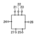
도 12a의 (1), 도 12a의 (2), 도 12b의 (1) 및 도 12b의 (2)는 일 실시 형태에 따른 단자부를 도시하는 도면.
도 13a의 (1), 도 13a의 (2), 도 13b의 (1) 및 도 13b의 (2)는 일 실시 형태에 따른 단자부를 도시하는 도면.
도 14a의 (1), 도 14a의 (2) 및 도 14b는 반도체 장치를 도시하는 도면.
도 15a 및 도 15b는 반도체 장치를 도시하는 도면.
도 16은 반도체 장치의 화소 등가 회로를 도시하는 도면.
도 17a 내지 도 17c는 반도체 장치를 도시하는 도면.
도 18a 및 도 18b는 표시 장치를 각각 도시하는 블록도.
도 19a는 신호선 구동 회로의 구성을 도시하는 도면이며, 도 19b는 그 동작을 도시하는 타이밍 차트.
도 20a 내지 도 20c는 시프트 레지스터의 구성을 도시하는 회로도이다.
도 21a는 시프트 레지스터의 회로도이고, 도 21b는 그 동작을 도시하는 타이밍 차트.
도 22는 반도체 장치를 도시하는 도면.
도 23은 반도체 장치를 도시하는 도면.
도 24a 및 도 24b는 전자 페이퍼의 응용을 도시하는 도면.
도 25는 전자 서적 리더(reader)의 일 예를 도시하는 외관도.
도 26a 및 도 26b는 텔레비전 장치 및 디지털 포토프레임을 각각 도시하는 외관도.
도 27a 및 도 27b는 게임기의 일 예를 도시하는 외관도.
도 28a 및 도 28b는 휴대형 컴퓨터의 일 예 및 휴대 전화기의 일 예를 각각 도시하는 외관도.
도 29는 반도체 장치를 도시하는 도면.
도 30은 반도체 장치를 도시하는 도면.
도 31은 반도체 장치를 도시하는 도면.
도 32는 반도체 장치를 도시하는 도면.
도 33은 반도체 장치를 도시하는 도면.
도 34는 반도체 장치를 도시하는 도면.
도 35는 반도체 장치를 도시하는 도면.
도 36은 반도체 장치를 도시하는 도면.
도 37은 반도체 장치를 도시하는 도면.
도 38은 일 실시 형태에 따른 표시 장치의 화소 구성의 일 예를 도시하는 도면.
도 39a 내지 도 39c는 일 실시 형태에 따른 표시 장치의 화소 구성의 일 예를 도시하는 도면.
도 40a 내지 도 40c는 일 실시 형태에 따른 표시 장치의 화소부의 제작 공정을 도시하는 도면.
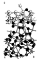
도 41a 내지 도 41c는 IGZO에서의 금속과 산소의 결정 구조를 도시하는 도면.
도 42a 및 도 42b는 텅스텐막과 산화물 반도체막 간의 계면 근방에서의 금속 원자와 산소 원자의 구조 모델을 도시하는 도면.
도 43a 및 도 43b는 몰리브덴막과 산화물 반도체막 간의 계면 근방에서의 금속 원자와 산소 원자의 구조 모델을 도시하는 도면.
도 44a 및 도 44b는 티타늄막과 산화물 반도체막 간의 계면 근방에서의 금속 원자와 산소 원자의 구조 모델을 도시하는 도면.
도 45는 루틸 구조를 갖는 이산화티탄의 결정 구조를 도시하는 도면.
도 46은 루틸 구조를 갖는 이산화티탄의 상태 밀도를 도시하는 도면.
도 47은 산소 결손 상태에서의 이산화티탄의 상태 밀도를 도시하는 도면.
도 48은 일산화티탄의 상태 밀도를 도시하는 도면.
도 49는 본 발명의 일 양태의 밴드(band)를 도시하는 도면.1A and 1B are diagrams illustrating a configuration of a display device according to an embodiment.
2A to 2B are diagrams illustrating an example of a pixel configuration of a display device according to an embodiment.
3 is a diagram illustrating an example of a pixel configuration of a display device according to an embodiment.
4A to 4D are diagrams illustrating steps of manufacturing a pixel portion of the display device according to an exemplary embodiment.
5A to 5C are diagrams illustrating steps of manufacturing a pixel portion of the display device according to an exemplary embodiment.
6A-6D are diagrams showing a gray-tone mask and a half-tone mask.
7A to 7E are diagrams illustrating steps of manufacturing a pixel portion of the display device according to an exemplary embodiment.
8A to 8C are diagrams showing an inverter circuit according to an embodiment.
9A and 9B are diagrams showing a protection circuit according to an embodiment.
Fig. 10 is a diagram showing a protection circuit according to an embodiment.
11A and 11B are diagrams showing a connection part according to an embodiment.
12A(1), 12A(2), 12B(1), and 12B(2) are views showing a terminal portion according to an embodiment.
13A(1), 13A(2), 13B(1), and 13B(2) are diagrams showing a terminal portion according to an embodiment.
14A(1), 14A(2), and 14B are diagrams showing a semiconductor device.
15A and 15B are diagrams showing a semiconductor device.
16 is a diagram showing a pixel equivalent circuit of a semiconductor device.
17A to 17C are diagrams showing a semiconductor device.
18A and 18B are block diagrams each showing a display device.
Fig. 19A is a diagram showing the configuration of a signal line driving circuit, and Fig. 19B is a timing chart showing its operation.
20A to 20C are circuit diagrams showing the configuration of a shift register.
Fig. 21A is a circuit diagram of the shift register, and Fig. 21B is a timing chart showing its operation.
22 is a diagram illustrating a semiconductor device.
23 is a diagram illustrating a semiconductor device.
24A and 24B are diagrams showing applications of electronic paper.
Fig. 25 is an external view showing an example of an electronic book reader.
26A and 26B are external views each showing a television device and a digital photo frame.
27A and 27B are external views showing an example of a game machine.
28A and 28B are external views respectively showing an example of a portable computer and an example of a mobile phone.
29 is a diagram illustrating a semiconductor device.
30 is a diagram showing a semiconductor device.
31 is a diagram illustrating a semiconductor device.
Fig. 32 is a diagram showing a semiconductor device.
33 is a diagram illustrating a semiconductor device.
Fig. 34 is a diagram showing a semiconductor device.
Fig. 35 is a diagram showing a semiconductor device.
36 is a diagram showing a semiconductor device.
37 is a diagram showing a semiconductor device.
38 is a diagram illustrating an example of a pixel configuration of a display device according to an embodiment.
39A to 39C are diagrams illustrating an example of a pixel configuration of a display device according to an embodiment.
40A to 40C are diagrams illustrating steps of manufacturing a pixel portion of the display device according to an exemplary embodiment.
41A to 41C are diagrams showing crystal structures of metal and oxygen in IGZO.
42A and 42B are diagrams showing structural models of metal atoms and oxygen atoms in the vicinity of an interface between a tungsten film and an oxide semiconductor film.
43A and 43B are diagrams showing structural models of metal atoms and oxygen atoms in the vicinity of an interface between a molybdenum film and an oxide semiconductor film.
44A and 44B are diagrams showing structural models of metal atoms and oxygen atoms in the vicinity of an interface between a titanium film and an oxide semiconductor film.
Fig. 45 is a diagram showing a crystal structure of titanium dioxide having a rutile structure.
Fig. 46 is a diagram showing the density of states of titanium dioxide having a rutile structure.
47 is a diagram showing the density of states of titanium dioxide in an oxygen-deficient state.
Fig. 48 is a diagram showing the density of states of titanium monoxide.
Figure 49 is a diagram showing a band of an aspect of the present invention.
실시 형태에 대해서, 도면을 참조하여 상세하게 설명한다. 단, 본 발명은 이하의 설명에 한정되지 않으며, 본 발명의 취지 및 그 범위로부터 일탈하지 않고 그 형태 및 상세를 다양한 방식으로 변경할 수 있음을 당업자라면 용이하게 이해할 것이다. 따라서, 본 발명은 이하에 기재하는 실시 형태의 기재 내용에 한정하여 해석되어서는 안된다. 이하에 설명하는 발명의 구성에 있어서, 동일 부분 또는 유사한 기능을 갖는 부분은 다른 도면에서도 동일한 참조 부호를 사용하고, 그러한 부분의 설명은 반복되지 않는다.Embodiments will be described in detail with reference to the drawings. However, it will be readily understood by those skilled in the art that the present invention is not limited to the following description, and that the form and detail can be changed in various ways without departing from the spirit and scope of the present invention. Therefore, the present invention should not be interpreted as being limited to the description of the embodiments described below. In the configuration of the invention described below, the same parts or parts having similar functions are denoted by the same reference numerals in other drawings, and descriptions of such parts are not repeated.
(실시 형태 1)(Embodiment 1)
본 실시 형태에서는, 화소부와, 산화물 반도체를 포함하며 화소부 주변에 설치되는 반도체 소자가 형성된 표시 장치의 일 양태가 도 1a, 및 도 1b를 참조하여 설명된다.In the present embodiment, an aspect of a display device including a pixel portion and an oxide semiconductor in which a semiconductor element provided around the pixel portion is formed is described with reference to FIGS. 1A and 1B.
도 1a는 표시 장치(30)의 구성을 도시한다. 표시 장치(30)는 기판(100) 위에 게이트 단자부(7) 및 소스 단자부(8)를 포함한다. 표시 장치(30)에는 게이트 배선(20_1) 및 게이트 배선(20_2)을 포함하는 게이트 배선(20_1 내지 20_n(단, n은 자연수))과, 소스 배선(60_1) 및 소스 배선(60_2)을 포함하는 소스 배선(60_1 내지 60_m(단, m은 자연수))이 설치되어 있다. 또한, 표시 장치(30)의 화소 영역(94)에는, 화소(93)가 매트릭스 형상으로 배열되어 있다. 각 화소(93)는 적어도 하나의 게이트 배선 및 하나의 소스 배선에 접속되어 있다.1A shows a configuration of a
또한, 표시 장치(30)는 공통 배선(44), 공통 배선(45), 공통 배선(46) 및 공통 배선(65)을 갖는다. 예를 들면, 공통 배선(45)은 접속부(95)를 통해 공통 배선(65)과 접속된다. 공통 배선은 서로 전기적으로 접속되어 등전위를 가진다.Further, the
또한, 공통 배선(44), 공통 배선(45), 공통 배선(46) 및 공통 배선(65)는 단자(71), 단자(75), 단자(81) 및 단자(85)와 각각 접속되어 있다. 공통 배선은 대향 기판과 전기적으로 접속될 수 있는 공통 접속부(96)를 각각 포함한다.In addition, the
또한, 게이트 단자부(7)의 각각의 게이트 신호선 단자(70_1 내지 70_i(단, i는 자연수))는 게이트 구동 회로(91)(이하, 주사선 구동 회로라고도 한다)와 접속되고, 보호 회로(97)를 통하여 공통 배선(46)과 접속되어 있다. 또한, 단자(74)는 게이트 구동 회로(91)와 접속되고, (도시되지 않은) 외부 전원과 게이트 구동 회로(91)를 접속한다. 각각의 게이트 배선(20_1 내지 20_n(단, n은 자연수))은 보호 회로(97)를 통하여 공통 배선(65)과 접속되어 있다.In addition, each of the gate signal line terminals 70_1 to 70_i (where i is a natural number) of the
또한, 소스 단자부(8)의 각각의 소스 신호선 단자(80_1 내지 80_k(단, k는 자연수))는 소스 구동 회로(92)(이하, 신호선 구동 회로라고도 한다)와 접속되고, 보호 회로(97)를 통하여 공통 배선(44)과 접속되어 있다. 또한, 단자(84)는 소스 구동 회로(92)와 접속되고, (도시되지 않은) 외부 전원과 소스 구동 회로(92)를 접속한다. 각각의 소스 배선(60_1 내지 60_m(단, m은 자연수))은 보호 회로(97)를 통하여 공통 배선(45)과 접속되어 있다.In addition, each of the source signal line terminals 80_1 to 80_k (where k is a natural number) of the source
게이트 구동 회로 및 소스 구동 회로는, 본 명세서에서 개시하는 박막 트랜지스터를 사용하여 화소 영역과 동시에 형성할 수 있다. 또한, 게이트 구동 회로 및 소스 구동 회로 중 어느 하나, 또는 양자 모두를, 별도 준비된 기판 위에 단결정 반도체막 또는 다결정 반도체막을 이용하여 형성하고,그 후에 COG법, 와이어 본딩법, TAB법 등을 이용하여 실장할 수도 있다.The gate driving circuit and the source driving circuit can be formed simultaneously with the pixel region using the thin film transistor disclosed herein. In addition, either or both of the gate driving circuit and the source driving circuit are formed using a single crystal semiconductor film or a polycrystalline semiconductor film on a separately prepared substrate, and then mounted using a COG method, a wire bonding method, a TAB method, etc. You may.
화소(93)에 적용할 수 있는 등가 회로의 일 예를 도 1b에 도시한다. 도 1b에 도시하는 등가 회로는, 액정 소자가 화소(93)의 표시 소자로서 사용되는 경우의 일 예이다.An example of an equivalent circuit applicable to the
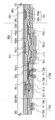
다음으로, 도 1a 및 도 1b에 도시된 표시 장치의 화소 구성의 일 예에 대하여 도 2a 내지 도 2c를 참조하여 설명한다. 도 2a는 화소의 평면 구성을 나타내는 평면도이며, 도 2b 및 도 2c는 화소의 적층 구성을 각각 나타내는 단면도이다. 도 2a의 쇄선 A1-A2, B1-B2 및 C1-C2는 도 2b의 단면 A1-A2, B1-B2 및 C1-C2에 각각 대응한다. 도 2a의 쇄선 D1-D2는 도 2c의 단면 D1-D2에 대응한다.Next, an example of a pixel configuration of the display device illustrated in FIGS. 1A and 1B will be described with reference to FIGS. 2A to 2C. 2A is a plan view illustrating a planar configuration of a pixel, and FIGS. 2B and 2C are cross-sectional views illustrating a stacked configuration of pixels. The chain lines A1-A2, B1-B2, and C1-C2 in Fig. 2A correspond to the cross sections A1-A2, B1-B2, and C1-C2 in Fig. 2B, respectively. The dashed line D1-D2 in FIG. 2A corresponds to the cross section D1-D2 in FIG. 2C.
단면 A1-A2 및 단면 D1-D2에서, 화소부에 사용되는 박막 트랜지스터(250)의 적층 구조를 나타내고 있다. 박막 트랜지스터(250)는 보텀(bottom) 게이트 구조를 가지는 박막 트랜지스터의 일 양태이다.Cross-sections A1-A2 and D1-D2 show a stacked structure of
단면 A1-A2 및 단면 D1-D2에서, 기판(200) 위에 설치된 절연층(201), 절연층(201) 위에 설치된 게이트 배선(202), 게이트 배선(202) 위에 설치된 게이트 배선(203), 게이트 배선(203) 위에 설치된 절연층(204), 절연층(204) 위에 설치된 반도체층(205), 반도체층(205) 위에 설치된 한 쌍의 전극(207a 및 207b), 전극(207a), 전극(207b) 및 반도체층(205) 위에 설치된 절연층(208), 절연층(208)에 설치된 개구부를 통하여 전극(207a)에 접촉하는 소스 배선(209), 소스 배선(209) 위에 설치된 소스 배선(210), 소스 배선(210) 위에 설치된 절연층(211), 절연층(211) 및 절연층(208)에 설치된 개구부를 통하여 전극(207b)에 접촉하는 전극(212)이 도시된다.In cross-sections A1-A2 and D1-D2, the insulating
또한, 단면 B1-B2에서, 축적 용량(Cs 용량이라고도 한다)의 적층 구조를 도시한다. 단면 B1-B2에서, 기판(200) 위의 절연층(201), 절연층(201) 위의 축적 용량 배선(213), 축적 용량 배선(213) 위의 축적 용량 배선(214), 축적 용량 배선(214) 위의 절연층(204), 절연층(204) 위의 전극(207b), 전극(207b) 위의 절연층(208), 절연층(208) 위의 절연층(211), 절연층(211) 위의 전극(212)이 도시된다.Further, in cross-sections B1-B2, a stacked structure of storage capacitors (also referred to as Cs capacitors) is shown. In cross section B1-B2, the insulating
또한, 단면 C1-C2에서, 게이트 배선과 소스 배선의 배선 교차부의 적층 구조가 도시되어 있다. 단면 C1-C2에서, 기판(200) 위의 절연층(201), 절연층(201) 위의 게이트 배선(202), 게이트 배선(202) 위의 게이트 배선(203), 게이트 배선(203) 위의 절연층(204), 절연층(204) 위의 절연층(208), 절연층(208) 위의 소스 배선(209), 소스 배선(209) 위의 소스 배선(210), 및 소스 배선(210) 위의 절연층(211)이 도시된다. 배선 교차부에서, 절연층(204)과 절연층(208)의 사이에 반도체층이 형성될 수도 있다.Further, in cross-sections C1-C2, the lamination structure of the wiring intersection of the gate wiring and the source wiring is shown. In cross section C1-C2, the insulating
또한, 본 발명의 일 양태는 도 2b에 도시하는 화소 구성에 한정되지 않는다. 도 2b와는 상이한 화소 구성의 일 예를 도 3에 도시한다. 도 3에 도시한 박막 트랜지스터(251)는, 보텀 게이트 구조를 가지는 박막 트랜지스터의 일 양태이며, 채널 보호형 박막 트랜지스터라고 부를 수 있다.In addition, one aspect of the present invention is not limited to the pixel configuration shown in Fig. 2B. An example of a pixel configuration different from that of FIG. 2B is shown in FIG. 3. The
박막 트랜지스터(251)는, 기판(200) 위에 설치된 절연층(201), 절연층(201) 위에 설치된 게이트 배선(202), 게이트 배선(202) 위에 설치된 게이트 배선(203), 게이트 배선(203) 위에 설치된 절연층(204), 절연층(204) 위에 설치된 반도체층(205), 반도체층(205) 위에 설치된 채널 보호층(225), 채널 보호층(225) 위에 설치된 한 쌍의 전극(207a 및 207b), 전극(207a), 전극(207b) 및 반도체층(205) 위에 설치된 절연층(208), 절연층(208)에 설치된 개구부를 통하여 전극(207a)에 접촉하는 소스 배선(209), 소스 배선(209) 위에 설치된 소스 배선(210), 소스 배선(210) 위에 설치된 절연층(211), 절연층(211) 및 절연층(208)에 설치된 개구부를 통하여 전극(207b)에 접촉하는 전극(212)을 포함한다.The
도 2b 또는 도 3에 도시된 화소 구성과는 상이한 화소 구성을 도 39a 내지 도 39c에 도시한다. 도 39a 내지 도 39c에 예시한 박막 트랜지스터(252)는, 기판(200) 위에 설치된 절연층(201), 절연층(201) 위에 설치된 게이트 배선(203), 게이트 배선(203) 위에 설치된 절연층(204), 절연층(204) 위에 설치된 반도체층(205), 반도체층(205) 위에 설치된 한 쌍의 전극(207a 및 207b), 전극(207a), 전극(207b) 및 반도체층(205) 위에 설치된 절연층(208), 절연층(208)에 설치된 개구부를 통하여 전극(207a)에 접촉하는 소스 배선(209), 소스 배선(209) 위에 설치된 절연층(211), 절연층(211) 및 절연층(208)에 설치된 개구부를 통하여 전극(207b)에 접촉하는 전극(212)을 포함한다.A pixel configuration different from the pixel configuration shown in FIG. 2B or 3 is shown in FIGS. 39A to 39C. The
배선 재료는 표시 장치가 요구되는 성능에 따라 적절히 선택될 수 있다. 예를 들면, 게이트 배선보다 높은 전달 특성이 요구되는 소스 배선(209)만을 Cu를 포함하는 배선을 사용하여 형성할 수도 있다.The wiring material can be appropriately selected according to the performance required of the display device. For example, only the
배선 재료로서 전기 저항이 낮은 Al을 주성분으로 포함하는 도전막을 게이트 배선(203)으로 이용할 경우, 도 39a 내지 도 39c에 도시한 바와 같이 박막 트랜지스터의 게이트 전극은 게이트 배선(203)과 동일한 구성을 가질 수 있다.When a conductive film containing Al as a main component of low electrical resistance as a wiring material is used as the
본 실시 형태에서 예시하는 화소의 축적 용량은, 절연층(204)이 게이트 배선과 동일한 층을 이용하여 형성하는 축적 용량 배선과 전극(207b) 사이에 개재되도록 형성한다. 전극(212) 및 소스 배선(210)과 비교하여, 전극(207b)은 축적 용량 배선에 두께 방향으로 근접하여 있으므로, 전극(207b)는 축적 용량에 적합하다.The storage capacitor of the pixel illustrated in this embodiment is formed so that the insulating
Cu를 포함하는 도전 재료를 사용하여 게이트 배선(202) 및 소스 배선(210)을 형성함으로써 배선 저항의 증가를 방지할 수 있다. 또한, W, Ta, Mo, Ti 또는 Cr 등의 Cu보다 융점이 높은 원소를 포함하는 도전 재료를 사용하여, 게이트 배선(202)에 접촉하며 피복하도록 게이트 배선(203)을 형성하는 경우, 게이트 배선(202)의 마이그레이션(migration)을 억제하여, 반도체 장치의 신뢰성을 향상시킬 수 있다. 또한,Cu를 포함하는 도전층의 위와 아래에 위치하는 절연층으로서 질화 규소를 포함하는 절연층을 제공하여, Cu를 포함하는 게이트 배선(202)이 절연층 사이에 개재되거나, 둘러싸도록 함으로써, Cu 확산을 방지할 수 있다.An increase in wiring resistance can be prevented by forming the
또한, 게이트 배선(202)은, 박막 트랜지스터의 채널이 형성되는 반도체층(205)과 중첩하지 않고, 게이트 배선(202)과 접촉하는 게이트 배선(203)의 일부를 연신하여 반도체층(205)과 중첩시켜 게이트 전극으로서 기능하도록 하는 방식으로 제공된다. 이러한 구성으로, 게이트 배선(202)에 포함되는 Cu가 박막 트랜지스터에 영향을 미치는 것을 방지할 수 있다.In addition, the
배선 교차부에서 게이트 배선과 소스 배선 사이에 적어도 절연층(204)과 절연층(208)을 개재시키도록 하여, 배선 사이의 두께 방향의 간격을 넓힐 수 있다. 그 결과, 배선 교차부의 기생 용량을 작게 할 수 있다.By interposing at least the insulating
본 실시 형태는 본 명세서의 임의의 다른 실시 형태와 적절하게 조합할 수 있다.This embodiment can be appropriately combined with any other embodiment of the present specification.
(실시 형태 2)(Embodiment 2)
본 실시 형태에서는, 실시 형태 1에서 설명한 표시 장치의 화소부의 제작 공정에 대해 도 4a 내지 도 4d 및 도 5a 내지 도 5c를 참조하여 설명한다. 도 4a 내지 도 4d, 및 도 5a 내지 도 5c에서의 단면 A1-A2, 단면 B1-B2, 단면 C1-C2 및 단면 D1-D2는, 각각 도 2a에서의 쇄선 A1-A2, B1-B2, C1-C2 및 D1-D2를 따라 취해진 단면도이다.In this embodiment, the manufacturing process of the pixel portion of the display device described in the first embodiment will be described with reference to FIGS. 4A to 4D and FIGS. 5A to 5C. Sections A1-A2, B1-B2, C1-C2, and D1-D2 in FIGS. 4A to 4D and 5A to 5C are dashed lines A1-A2, B1-B2, and C1 in FIG. 2A, respectively. It is a cross-sectional view taken along -C2 and D1-D2.
우선, 기판(200) 위에 질화 규소를 포함하는 절연층(201)을 50nm 이상 300nm 이하, 바람직하게는 100nm 이상 200nm 이하의 두께로 형성한다. 기판(200)으로서, 글래스 기판 및 세라믹 기판 외에, 본 제작 공정의 처리 온도를 견딜 수 있는 내열성을 갖는 플라스틱 기판 등을 이용할 수 있다. 기판에 투광성을 필요로 하지 않을 경우에는, 표면 위에 절연층이 제공된 스테인레스강 합금 기판 등의 금속 기판이 사용될 수 있다. 글래스 기판으로서, 예를 들면, 바륨 붕규산 글래스, 알루미노 붕규산 글래스, 알루미노 규산 글래스 등의 무알칼리 글래스 기판을 사용할 수도 있다. 이와 달리, 석영 기판, 사파이어 기판 등을 사용할 수 있다. 또한, 기판(200)으로서, 제3 세대(550mm×650mm), 제3.5 세대(600mm×720mm 또는 620mm×750mm), 제4 세대(680mm×880mm 또는 730mm×920mm), 제5 세대(1100mm×1300mm), 제6 세대(1500mm×1850mm), 제7 세대(1870mm×2200mm), 제8 세대(2200mm×2400mm), 제9 세대(2400mm×2800mm 또는 2450mm×3050mm) 또는 제10 세대(2950mm×3400mm) 사이즈 중 임의의 것을 가지는 글래스 기판을 이용할 수 있다. 본 실시 형태에서는 기판(200)으로 알루미노 붕규산 글래스를 사용한다.First, an insulating
절연층(201)은 질화 규소막 및/또는 질화 산화 규소막을 단일층 또는 적층하여 형성할 수 있다. 본 명세서에서, 질화 산화 규소는 산소보다 질소를 더 포함하는 것을 지칭하며, RBS 및 HFS를 이용하여 측정한 경우에, 산소, 질소, 규소 및 수소가 각각 5 원자% 내지 30 원자%, 20 원자% 내지 55 원자%, 25 원자% 내지 35 원자% 및 10 원자% 내지 30 원자%의 범위의 농도로 포함하는 것을 지칭한다. 절연층(201)은 스퍼터링법, CVD법, 도포법, 인쇄법 등에 의해 적절하게 형성될 수 있다. 본 실시 형태에서는, 절연층(201)으로서 100nm 두께의 질화 규소막을 형성한다. 막은 인(P) 또는 붕소(B)로 도핑될 수도 있다.The insulating
다음으로, 절연층(201) 위에 스퍼터링법, 진공 증착법 또는 도금법에 의해 100nm 이상 500nm 이하, 바람직하게는 200nm 이상 300nm 이하의 두께로 Cu를 포함하는 도전막을 형성한다. 도전막 위에 포토리소그래피법, 잉크젯법 등에 의해 마스크를 형성하고, 마스크를 사용하여 도전막을 에칭해서 게이트 배선(202) 및 축적 용량 배선(213)을 형성할 수 있다. 게이트 배선(202)의 밀착성을 개선하기 위해서, W, Ta, Mo, Ti, Cr 등을 포함하는 금속층, 혹은 이들의 임의의 조합을 포함하는 합금층, 혹은 이들 중 임의의 것의 질화물이나 산화물의 층을 절연층(201)과 게이트 배선(202)의 사이에 형성할 수도 있다.Next, a conductive film containing Cu is formed on the insulating
레지스트 마스크를 잉크젯법에 의해 형성할 경우, 포토마스크를 사용하지 않아 제조 비용을 저감시킬 수 있다. 또한, 구리 등의 도전성 나노 페이스트를 잉크젯법에 의해 기판 위에 토출시키고 소성할 경우, 저비용으로 게이트 배선(202) 및 축적 용량 배선(213)을 형성할 수 있다.When the resist mask is formed by the inkjet method, manufacturing cost can be reduced by not using a photomask. Further, when a conductive nano paste such as copper is discharged onto a substrate by an ink jet method and fired, the
본 실시 형태에서는, 절연층(201) 위에 두께 250nm의 Cu막을 형성하고, 제1 포토리소그래피 공정에 의해 형성한 레지스트 마스크를 이용하여 Cu막을 선택적으로 에칭하여, 게이트 배선(202) 및 축적 용량 배선(213)을 형성한다(도 4a 참조).In this embodiment, a Cu film having a thickness of 250 nm is formed on the insulating
다음으로, 게이트 배선(202) 위에 스퍼터링법, 진공 증착법 등에 의해 W, Ta, Mo, Ti 또는 Cr 등의 Cu보다 융점이 높은 원소, 또는 이등 원소의 임의의 것의 조합을 포함하는 합금 등의 도전막을, 5nm 이상 200nm 이하, 바람직하게는 10nm 이상 100nm 이하의 두께로 형성한다. 도전막은, 상술한 원소 중 임의의 것을 포함하는 단일층에 한정되지 않고, 2 이상의 층의 적층막일 수 있다. 본 실시 형태에서는, 두께 200nm의 텅스텐 단일층을 도전막으로서 형성한다.Next, on the
다음에, 도전막 위에 포토리소그래피법, 잉크젯법 등에 의해 마스크를 형성하고, 그 후에 마스크를 사용하여 도전막을 에칭해서 게이트 배선(203) 및 축적 용량 배선(214)을 형성할 수 있다. 본 실시 형태에서는, 제2 포토리소그래피 공정에 의해 형성된 레지스트 마스크를 사용하여 도전막을 선택적으로 에칭하여, 게이트 배선(203) 및 축적 용량 배선(214)을 형성한다(도 4b 참조).Next, a mask is formed on the conductive film by a photolithography method, an inkjet method, or the like, and then the conductive film is etched using the mask to form the
게이트 배선 및 축적 용량 배선은, Cu보다 융점이 높은 원소를 포함하는 도전층이 Cu를 포함하는 도전 재료를 덮는 구조를 가지도록 형성된다. 이러한 구성으로, Cu를 포함하는 층의 마이그레이션을 억제하여, 반도체 장치의 신뢰성을 향상시킬 수 있다.The gate wiring and the storage capacitor wiring are formed so that a conductive layer containing an element having a melting point higher than that of Cu has a structure covering a conductive material containing Cu. With this configuration, migration of the layer containing Cu can be suppressed, and the reliability of the semiconductor device can be improved.
다음에, 게이트 배선(203) 위에, 게이트 절연층으로서 기능하는 절연층(204)을 50nm 이상 800nm 이하, 바람직하게는 100nm 이상 600nm 이하의 두께로 형성한다. 본 실시 형태에서는, 절연층(204a) 및 절연층(204b)을 이 순서대로 적층하여 절연층(204)을 형성한다. 스퍼터링법에 의해 질화 규소층(SiNy(y>0))을 절연층(204a)으로서 형성하고, 산화 규소층(SiOx(x>0))을 절연층(204a) 위에 절연층(204b)으로서 형성하여, 막 두께 100nm의 게이트 절연층(204)을 형성한다.Next, on the
절연층(204)은 보호층으로서도 기능한다. Cu를 포함하는 도전층의 위와 아래의 절연층으로서 질화 규소를 포함하는 절연층을 제공함으로써, 절연층에 의해 Cu를 포함하는 도전층을 개재하거나, 또는 둘러쌈으로써, Cu 확산을 방지할 수 있다.The insulating
다음에, 절연층(204) 위에 반도체층(205)을 형성한다. 반도체층(205)의 역할을 하는 산화물 반도체막으로서, In-Ga-Zn-O계 산화물 반도체막, In-Sn-Zn-O계 산화물 반도체막, In-Al-Zn-O계 산화물 반도체막, Sn-Ga-Zn-O계 산화물 반도체막, Al-Ga-Zn-O계 산화물 반도체막, Sn-Al-Zn-O계 산화물 반도체막, In-Zn-O계 산화물 반도체막, Sn-Zn-O계 산화물 반도체막, Al-Zn-O계 산화물 반도체막, In-O계 산화물 반도체막, Sn-O계 산화물 반도체막 또는 Zn-O계 산화물 반도체막을 사용한다. 또한, 산화물 반도체막은 희가스(대표적으로는 아르곤) 분위기, 산소 분위기, 또는 희가스(대표적으로는 아르곤) 및 산소의 혼합 분위기 하에서의 스퍼터법에 의해 형성할 수 있다.Next, a
스퍼터법을 이용할 경우, 산화 규소(SiO2)를 2중량% 이상 10중량% 이하로 포함하는 타깃을 사용하여 성막을 행하여 산화물 반도체막에 결정화를 저해하는 SiOx(x>0)을 포함시켜서 결정화를 억제할 수 있다. 이것은 이후의 공정에서 가열 처리를 행할 경우에 특히 효과적이다.In the case of using the sputtering method, a target containing 2% by weight or more and 10% by weight or less of silicon oxide (SiO 2 ) is used to form a film, and the oxide semiconductor film is crystallized by including SiO x (x> 0), which inhibits crystallization. Can be suppressed. This is particularly effective when heat treatment is performed in a subsequent step.
여기에서는, In, Ga 및 Zn을 포함하는 금속 산화물 타깃(조성비: In2O3:Ga2O3:ZnO=1:1:1 [mol%], In:Ga:Zn=1:1:0.5 [at.%])을 사용하여, 기판과 타깃 사이의 거리를 100mm, 압력 0.6Pa, 직류(DC) 전원 0.5kW, 산소(산소 유량비율 100%) 분위기하에서 성막한다. 펄스 직류(DC) 전원을 이용하면, 성막 시에 발생하는 분말형 물질(파티클 또는 먼지라고도 한다)을 경감시킬 수 있고, 막 두께 분포도 균일해지므로 바람직하다. 본 실시 형태에서는, 산화물 반도체막으로서, In-Ga-Zn-O계 금속 산화물 타깃을 사용하여 스퍼터법에 의해 In-Ga-Zn-O계 막을 성막한다.Here, a metal oxide target containing In, Ga, and Zn (composition ratio: In 2 O 3 :Ga 2 O 3 :ZnO=1:1:1 [mol%], In:Ga:Zn=1:1:0.5 [at.%]), the distance between the substrate and the target is 100 mm, a pressure of 0.6 Pa, a direct current (DC) power supply of 0.5 kW, and an oxygen (oxygen flow rate of 100%) atmosphere. If a pulsed direct current (DC) power supply is used, powdery substances (also referred to as particles or dust) generated during film formation can be reduced, and the film thickness distribution becomes uniform, which is preferable. In this embodiment, an In-Ga-Zn-O-based film is formed by sputtering using an In-Ga-Zn-O-based metal oxide target as the oxide semiconductor film.
산화물 반도체 타깃의 충전율은 90% 이상 100% 이하, 바람직하게는 95% 이상 99.9% 이하이다. 충전율이 높은 산화물 반도체 타깃을 사용함으로써, 치밀한 산화물 반도체막이 성막된다.The filling rate of the oxide semiconductor target is 90% or more and 100% or less, and preferably 95% or more and 99.9% or less. By using an oxide semiconductor target with a high filling rate, a dense oxide semiconductor film is formed.
산화물 반도체막은 바람직하게는 5nm 이상 30nm 이하의 두께를 가진다. 산화물 반도체 재료에 따라 적절한 두께는 상이하고, 재료에 따라서 적절하게 두께를 설정할 수 있다.The oxide semiconductor film preferably has a thickness of 5 nm or more and 30 nm or less. The appropriate thickness is different depending on the oxide semiconductor material, and the thickness can be appropriately set according to the material.
본 실시 형태에서, 산화물 반도체막을 게이트 절연층(204) 위에 연속 성막한다. 여기에서 사용하는 멀티챔버 스퍼터링 장치는, 규소 혹은 산화 규소(인공 석영)의 타깃과, 산화물 반도체막용의 타깃을 구비하고 있다. 산화물 반도체막용의 타깃을 설치한 성막실은 적어도 배기 유닛으로서 크라이오 펌프(cryopump)를 더 구비한다. 크라이오 펌프 대신에 터보 분자 펌프를 사용하고, 터보 분자 펌프의 흡기구에 수분 등을 흡착시키기 위해 콜드 트랩을 설치할 수도 있다.In this embodiment, an oxide semiconductor film is continuously formed over the
크라이오 펌프를 사용하여 배기시킨 성막실에서는, 수소 원자, H2O 등 수소 원자를 포함하는 화합물, 탄소 원자를 포함하는 화합물 등이 제거되므로, 성막실에서 성막한 산화물 반도체막에 포함되는 불순물의 농도를 저감시킬 수 있다.In the deposition chamber evacuated using a cryopump, compounds containing hydrogen atoms, such as hydrogen atoms and H 2 O, compounds containing carbon atoms, etc. are removed. Therefore, impurities contained in the oxide semiconductor film formed in the deposition chamber are removed. The concentration can be reduced.
산화물 반도체막은 기판을 가열한 상태에서 성막한다. 본 실시 형태에서는, 기판 온도를 100℃ 이상 600℃ 이하, 바람직하게는 200℃ 이상 400℃ 이하로 설정한다. 기판을 가열한 상태에서 산화물 반도체막을 성막함으로써, 성막된 산화물 반도체막에 포함되는 불순물 농도를 저감시킬 수 있다. 또한, 산화물 반도체에 포함되는 원소의 조성비를 제어하기 위해서, 가열 온도는 가능한 한 저온인 것이 바람직하다. 예를 들면, 아연을 포함하는 산화물 반도체의 경우, 아연은 증기압이 높기 때문에, 고온에서 성막된 반도체층에 포함되는 아연의 비율이 저하된다. 스퍼터링 조건은 산화물 반도체막에 손상을 주지 않도록, 가능한 한 온화한 조건으로 설정한다.The oxide semiconductor film is formed while the substrate is heated. In this embodiment, the substrate temperature is set to 100°C or more and 600°C or less, preferably 200°C or more and 400°C or less. By forming the oxide semiconductor film while the substrate is heated, the concentration of impurities contained in the formed oxide semiconductor film can be reduced. Further, in order to control the composition ratio of the elements contained in the oxide semiconductor, the heating temperature is preferably as low as possible. For example, in the case of an oxide semiconductor containing zinc, since zinc has a high vapor pressure, the proportion of zinc contained in the semiconductor layer formed at a high temperature decreases. The sputtering conditions are set to be as mild as possible so as not to damage the oxide semiconductor film.
스퍼터법의 예는, 스퍼터 전원으로서 고주파 전원을 사용하는 RF 스퍼터법, DC 스퍼터법 및 펄스 방식으로 바이어스를 인가하는 펄스 DC 스퍼터법을 포함한다. RF 스퍼터법은 주로 절연막을 성막하는 경우에 이용되고, DC 스퍼터법은 주로 금속 도전막을 성막하는 경우에 이용된다.Examples of the sputtering method include an RF sputtering method using a high-frequency power source as a sputtering power source, a DC sputtering method, and a pulsed DC sputtering method in which a bias is applied by a pulse method. The RF sputtering method is mainly used when forming an insulating film, and the DC sputtering method is mainly used when forming a metal conductive film.
또한, 상이한 재료의 복수의 타깃을 설정할 수 있는 다원 스퍼터 장치도 있다. 다원 스퍼터 장치는, 동일 챔버에서 상이한 재료막을 적층 성막하거나, 동일 챔버에서 복수 종류의 재료를 동시에 방전시켜서 성막할 수 있다.There is also a multi-way sputtering apparatus capable of setting a plurality of targets of different materials. The multi-element sputtering device can be formed by laminating different material films in the same chamber, or simultaneously discharging a plurality of types of materials in the same chamber.
또한, 챔버 내부에 자석 기구를 구비하고, 마그네트론 스퍼터법에 이용되는 스퍼터 장치와, 글로우 방전을 사용하지 않고 마이크로파를 이용하여 발생시킨 플라즈마를 사용하는 ECR 스퍼터법에 이용되는 스퍼터 장치가 있다.In addition, there is a sputtering device provided with a magnetic mechanism inside the chamber and used in the magnetron sputtering method, and a sputtering device used in the ECR sputtering method using plasma generated using microwaves without using a glow discharge.
또한, 스퍼터에 의한 성막 방법으로서, 성막 중에 타깃 물질과 스퍼터 가스 성분을 서로 화학 반응시켜서 그것들의 화합물 박막을 형성하는 반응성 스퍼터법과, 성막 중에 기판에도 전압이 인가되는 바이어스 스퍼터법도 있다.Further, as a film formation method by sputtering, there are also a reactive sputtering method in which a target substance and a sputtering gas component are chemically reacted with each other during film formation to form a thin film of these compounds, and a bias sputtering method in which a voltage is applied to a substrate during film formation.
산화물 반도체막을 스퍼터법에 의해 성막하기 전에, 아르곤 가스를 도입하여 플라즈마를 발생시키는 역 스퍼터를 행하여, 게이트 절연층(204)의 표면에 부착되어 있는 먼지를 제거하는 것이 바람직하다. 역 스퍼터는, 아르곤 분위기에서 기판 측에 RF 전원을 이용하여 전압을 인가하고, 기판 근방에 플라즈마를 형성하여 표면을 개질하는 방법을 지칭한다. 아르곤 분위기 대신에 질소 분위기, 헬륨 분위기, 산소 분위기 등을 이용할 수도 있다.Before forming the oxide semiconductor film by the sputtering method, it is preferable to perform reverse sputtering to generate plasma by introducing argon gas to remove dust adhering to the surface of the
다음에, 산화물 반도체막 위에 포토리소그래피법, 잉크젯법 등에 의해 마스크를 형성하고, 마스크를 사용하여 산화물 반도체막을 선택적으로 에칭해서 섬 형상의 반도체층(205)을 형성한다. 본 실시 형태에서는, 제3 포토리소그래피 공정에 의해 형성된 레지스트 마스크를 사용하여 산화물 반도체막을 선택적으로 에칭해서, 섬 형상의 반도체층(205)이 된다(도 4c 참조).Next, a mask is formed on the oxide semiconductor film by a photolithography method, an inkjet method, or the like, and the oxide semiconductor film is selectively etched using the mask to form an island-shaped
다음에, 도 2a 내지 도 2c, 도 3, 도 4a 내지 도 4d, 및 도 5a 내지 도 5c에 도시하지 않지만, 게이트 배선(203)과, 후에 설명하는 전극(207a) 또는 전극(207b)을 접속하기 위한 개구부(컨택트 홀이라고도 한다)를 절연층(204)에 형성한다. 절연층(204) 위에 포토리소그래피법, 잉크젯법 등에 의해 마스크를 형성하고, 그 후에 마스크를 사용하여 절연층(204)을 선택적으로 에칭해서 컨택트 홀을 형성한다. 여기에서는, 제4 포토리소그래피 공정에 의해 형성한 레지스트 마스크를 사용해서 절연층(204)을 선택적으로 에칭하여, 컨택트 홀을 형성한다.Next, although not shown in FIGS. 2A to 2C, 3, 4A to 4D, and 5A to 5C, the
제4 포토리소그래피 공정에 의한 컨택트 홀의 형성은, 절연층(204)의 형성 후, 반도체층(205) 형성 전에 행할 수도 있다.The contact hole formation by the 4th photolithography process may be performed after the formation of the insulating
다음에, 산화물 반도체층(205) 위에 도전막을 형성한다. 도전막으로는, W, Ta, Mo, Ti, Cr, Al, 이들 원소의 조합을 포함하는 합금 등을 사용할 수 있다. 이와 달리, 도전막으로서 질화 티타늄, 질화 탄탈, 또는 질화 텅스텐 등의 금속 질화물을 사용할 수도 있다. 도전막은 2층 이상의 적층 구조를 가질 수 있다.Next, a conductive film is formed over the
200℃ 내지 600℃에서 열처리를 행할 경우에는, 도전막이 이 열처리에 견디는 내열성을 가지는 것이 바람직하다. 예를 들면, 힐록(hillock) 방지 원소가 첨가된 알루미늄 합금이나, 내열성 도전막과 적층한 도전막을 사용하는 것이 바람직하다.When heat treatment is performed at 200°C to 600°C, it is preferable that the conductive film has heat resistance to withstand this heat treatment. For example, it is preferable to use an aluminum alloy to which an anti-hillock element is added, or a conductive film laminated with a heat-resistant conductive film.
산화물 반도체층(205)에 접촉하는 도전막은 산소 친화성이 높은 금속을 포함하는 재료가 바람직하다.The conductive film in contact with the
산소 친화성이 높은 금속으로는, 티타늄(Ti), 망간(Mn), 알루미늄(Al), 마그네슘(Mg), 지르코늄(Zr), 베릴륨(Be) 및 토륨(Th)로부터 선택되는 하나 이상의 재료가 바람직하다. 본 실시 형태에서는 티타늄막을 사용한다.As the metal with high oxygen affinity, at least one material selected from titanium (Ti), manganese (Mn), aluminum (Al), magnesium (Mg), zirconium (Zr), beryllium (Be) and thorium (Th) desirable. In this embodiment, a titanium film is used.
산화물 반도체층과 산소 친화성이 높은 도전막을 서로 접촉시켜 형성하면, 계면 부근의 캐리어 밀도가 증가하고, 저저항의 영역이 형성되어, 산화물 반도체층과, 도전막 간의 컨택트 저항을 저감시킬 수 있다. 이는 산소 친화성이 높은 도전막이 산화물 반도체층으로부터 산소를 뽑아냄으로써, 산화물 반도체층과 도전막의 계면에, 산화물 반도체층 내의 금속을 과잉 포함하는 층(이러한 층은 복합층이라고 부른다) 또는 산화된 도전막 중 어느 하나, 혹은 그 양방이 형성되기 때문이다. 예를 들면, In-Ga-Zn-O계의 산화물 반도체층과 티타늄막이 접촉하는 구성에서는, 어떤 경우에는 산화물 반도체층과 티타늄막이 접촉하는 계면 부근에 인듐이 과잉인 층과 산화 티타늄층이 생성된다. 다른 경우에는, 산화물 반도체층과 티타늄막이 접촉하는 계면 부근에 인듐이 과잉인 층 및 산화 티타늄층 중 하나가 생성된다. 산소가 결손된 In-Ga-Zn-O계의 산화물 반도체층인 인듐이 과잉인 층은 전기 전도도가 높아, 산화물 반도체층과 도전막 간의 접촉 저항을 저감할 수 있다.When the oxide semiconductor layer and the conductive film having high oxygen affinity are formed in contact with each other, the carrier density in the vicinity of the interface increases, a region of low resistance is formed, and the contact resistance between the oxide semiconductor layer and the conductive film can be reduced. This is because a conductive film having a high oxygen affinity extracts oxygen from the oxide semiconductor layer, and at the interface between the oxide semiconductor layer and the conductive film, a layer containing an excess of metal in the oxide semiconductor layer (such a layer is called a composite layer) or an oxidized conductive film. This is because either or both are formed. For example, in a configuration in which an In-Ga-Zn-O-based oxide semiconductor layer and a titanium film are in contact, in some cases, an excessive indium layer and a titanium oxide layer are formed near the interface where the oxide semiconductor layer and the titanium film contact. . In other cases, one of an excess indium layer and a titanium oxide layer is formed in the vicinity of the interface where the oxide semiconductor layer and the titanium film are in contact. An oxygen-deficient In-Ga-Zn-O-based oxide semiconductor layer, a layer having an excess of indium, has high electrical conductivity, and can reduce contact resistance between the oxide semiconductor layer and the conductive film.
산화물 반도체층과 접촉하는 도전막으로서 도전성을 갖는 산화 티타늄막을 사용할 수도 있다. 그러한 경우에, In-Ga-Zn-O계의 산화물 반도체층과 산화 티타늄막이 접촉하는 구성에서, 산화물 반도체층과 산화 티타늄막이 접촉하는 계면 부근에 인듐이 과잉인 층이 형성될 수도 있다.As the conductive film in contact with the oxide semiconductor layer, a conductive titanium oxide film may be used. In such a case, in a configuration in which the In-Ga-Zn-O-based oxide semiconductor layer and the titanium oxide film are in contact, a layer with an excess of indium may be formed near the interface where the oxide semiconductor layer and the titanium oxide film are in contact.
전술한 In-Ga-Zn-O계 산화물 반도체막을 박막 트랜지스터의 활성층으로서 사용한 채널 에치 박막 트랜지스터에서, 소스 전극 및 드레인 전극으로 사용하는 금속막과 In-Ga-Zn-O계 산화물 반도체막 간의 계면 근방에, 다른 영역보다 높은 농도의 인듐을 포함하는 층(In이 풍부한 층) 및 산화 티타늄막(TiOx)이 형성되는 현상에 대해서는 실시 형태 14에서 자세하게 설명한다.In the channel etch thin film transistor using the aforementioned In-Ga-Zn-O-based oxide semiconductor film as the active layer of the thin-film transistor, near the interface between the metal film used as the source and drain electrodes and the In-Ga-Zn-O-based oxide semiconductor film Here, a phenomenon in which a layer containing indium having a higher concentration than other regions (the layer rich in In) and the titanium oxide film (TiO x ) is formed will be described in detail in
도전막은 100nm 이상 500nm 이하, 바람직하게는 200nm 이상 300nm 이하의 두께로 형성한다. 도전막의 성막 방법으로서, 스퍼터법, 진공 증착법(전자빔 증착법 등), 아크 방전 이온 플래팅법, 또는 스프레이법을 이용한다. 이와 달리, 도전막은 스크린 인쇄법, 잉크젯법 등에 의해 은, 금, 구리 등의 도전성 나노페이스트를 토출시키고, 나노페이스트를 소성하여 형성할 수도 있다.The conductive film is formed to have a thickness of 100 nm or more and 500 nm or less, and preferably 200 nm or more and 300 nm or less. As a method of forming a conductive film, a sputtering method, a vacuum vapor deposition method (e.g. electron beam vapor deposition method), an arc discharge ion plating method, or a spray method is used. Alternatively, the conductive film may be formed by discharging a conductive nanopaste such as silver, gold, or copper by a screen printing method, an inkjet method, or the like, and firing the nanopaste.
다음에, 도전막 위에 포토리소그래피법, 잉크젯법 등에 의해 마스크를 형성하고, 마스크를 사용하여 도전막을 에칭하여, 소스 전극으로서 기능하는 전극(207a) 및 드레인 전극으로서 기능하는 전극(207b)을 형성할 수 있다. 본 실시 형태에서는, 도전막으로서 스퍼터링법에 의해 두께 200nm의 Ti막을 형성하고, 그 다음에 제5 포토리소그래피 공정에 의해 형성한 레지스트 마스크를 사용해서, 드라이 에칭법에 의해 도전막을 선택적으로 에칭하여, 전극(207a 및 207b)을 형성한다.Next, a mask is formed on the conductive film by a photolithography method, an inkjet method, etc., and the conductive film is etched using the mask to form an
제5 포토리소그래피 공정에 의해 산화물 반도체층 위에서 산화물 반도체층과 접촉하는 도전막의 부분만을 선택적으로 제거한다. 산화물 반도체층 위에서 산화물 반도체층과 접촉하는 도전막의 부분만을 제거하도록 알칼리성의 에천트로서 암모니아 과산화혼합물(중량비로 과산화수소:암모니아:물=5:2:2) 등을 사용하면, 금속 도전막을 선택적으로 제거하고, In-Ga-Zn-O계 산화물 반도체를 포함하는 산화물 반도체층을 잔존시킬 수 있다.Only a portion of the conductive film in contact with the oxide semiconductor layer on the oxide semiconductor layer is selectively removed by a fifth photolithography process. If an ammonia peroxide mixture (hydrogen peroxide:ammonia:water = 5:2:2 by weight ratio) is used as an alkaline etchant to remove only the portion of the conductive film in contact with the oxide semiconductor layer on the oxide semiconductor layer, the metal conductive film is selectively removed. In addition, an oxide semiconductor layer including an In-Ga-Zn-O-based oxide semiconductor can remain.
또한, 에칭 조건에 따라, 어떤 경우에는 제5 포토리소그래피 공정에 의해 산화물 반도체층의 노출 영역이 에칭된다. 그러한 경우, 소스 전극층과 드레인 전극층 사이의 영역(참조 부호 207a와 207b 사이의 영역)의 산화물 반도체층의 두께는, 게이트 배선(203) 위에 소스 전극층과 겹치는 영역의 산화물 반도체층의 두께, 또는 게이트 배선(203) 위에 드레인 전극층과 겹치는 영역의 산화물 반도체층의 두께보다 얇다(도 4d 참조).Further, depending on the etching conditions, in some cases, the exposed region of the oxide semiconductor layer is etched by the fifth photolithography process. In such a case, the thickness of the oxide semiconductor layer in the region between the source electrode layer and the drain electrode layer (region between 207a and 207b) is the thickness of the oxide semiconductor layer in the region overlapping the source electrode layer on the
다음에, 절연층(208)을 게이트 절연층(204) 및 산화물 반도체층(205) 위에 형성한다. 절연층(208)은 수분, 수소 이온, 또는 OH- 등의 불순물을 포함하지 않고, 이들이 외부로부터 침입하는 것을 방지하는 무기절연막을 사용하여 형성한다. 또한, 절연층(208)은 이후의 공정에서 형성하는 소스 배선으로부터, Cu를 포함하는 층의 마이그레이션을 억제하는 무기절연막을 사용하여 형성한다. 본 실시 형태에서는, 절연층(208a) 및 절연층(208b)을 이 순서대로 적층하여 절연층(208)을 형성한다.Next, an insulating
산화물 반도체층(205)과 접촉하는 절연층(208a)으로 산화물 절연막을 사용한다. 절연층(208a)은 스퍼터링법과 같이 산화물 절연막에 물 또는 수소 등의 불순물을 혼입시키지 않는 방법에 의해 적어도 1nm의 두께로 적절하게 형성할 수 있다. 대표적으로는 산화 규소막, 질화 산화 규소막, 산화 알루미늄막, 산화 질화 알루미늄막 등 중 임의의 것을 이용하여 단일층 또는 적층하여 형성한다.An oxide insulating film is used as the insulating
성막 시의 기판 온도는 실온 이상 300℃ 이하일 수 있으며, 본 실시 형태에서는 100℃이다. 산화 규소막은 희가스(대표적으로는 아르곤) 분위기, 산소 분위기, 또는 희가스(대표적으로는 아르곤) 및 산소 분위기에서 스퍼터링법에 의해 성막될 수 있다. 스퍼터법에 의해 형성한 산화물 절연막은 특히 치밀하며, 산화물 절연막의 단일층이 불순물이 접촉하는 층으로 확산되는 현상을 억제하는 보호막으로서 이용될 수 있다. 또한, 인(P)이나 붕소(B)를 도프한 타깃을 사용하여, 산화물 절연막에 인(P)이나 붕소(B)를 첨가할 수도 있다.The substrate temperature at the time of film formation may be room temperature or more and 300°C or less, and in this embodiment, it is 100°C. The silicon oxide film may be formed by a sputtering method in a rare gas (typically argon) atmosphere, an oxygen atmosphere, or a rare gas (typically argon) and oxygen atmosphere. The oxide insulating film formed by the sputtering method is particularly dense, and can be used as a protective film for suppressing diffusion of a single layer of the oxide insulating film into a layer in contact with impurities. Further, phosphorus (P) or boron (B) may be added to the oxide insulating film using a target doped with phosphorus (P) or boron (B).
타깃으로서 산화 규소 타깃 또는 규소 타깃을 사용할 수 있고, 특히 규소 타깃이 바람직하다. 규소 타깃을 사용하여 산소 및 희가스 분위기에서 스퍼터링법에 의해 성막한 산화 규소막은 규소 원자 또는 산소 원자의 많은 수의 댕글링 본드(dangling bond)를 포함하고 있다.As the target, a silicon oxide target or a silicon target can be used, and a silicon target is particularly preferable. The silicon oxide film formed by sputtering in an oxygen and rare gas atmosphere using a silicon target contains a large number of dangling bonds of silicon atoms or oxygen atoms.
절연층(208a)은 많은 댕글링 본드를 포함하므로, 산화물 반도체층(205)에 포함되는 불순물은, 산화물 반도체층(205)과 절연층(208a)이 접촉하는 계면을 통하여 절연층(208a)으로 확산되기 쉬워진다. 구체적으로는, 산화물 반도체층(205) 내의 수소 원자, H2O 등 수소 원자를 포함하는 화합물, 탄소 원자를 포함하는 화합물 등이 절연층(208a)으로 확산 이동되기 쉬워져 절연층(208a)에 고정된다.Since the insulating
본 실시 형태에서는, 순도가 6N이고 붕소로 도프된 주상 다결정 규소 타깃(저항값 0.01Ωcm)을 사용하여, 기판과 타깃의 사이와의 거리(T-S 거리)를 89mm, 압력 0.4Pa, 직류(DC) 전원 6kW, 산소(산소 유량 비율 100%) 분위기의 조건에서 펄스 DC 스퍼터법에 의해 성막한다. 막 두께는 300nm이다.In this embodiment, using a columnar polycrystalline silicon target (resistance value of 0.01 Ωcm) doped with boron with a purity of 6N, the distance (TS distance) between the substrate and the target is 89 mm, pressure 0.4 Pa, direct current (DC) The film is formed by pulsed DC sputtering under conditions of a power supply of 6 kW and an oxygen (oxygen flow rate of 100%) atmosphere. The film thickness is 300 nm.
이 단계에서, 산화물 반도체층(205)과 산화물 절연층(208a)이 접촉하는 영역이 형성된다. 게이트 전극에 중첩하고, 게이트 절연층(204)과 절연층(208a) 사이에 접촉하여 개재된 산화물 반도체층(205)의 영역이 채널 형성 영역의 기능을 한다. 또한, 절연층(208a)은 채널 보호층으로서 기능한다.In this step, a region where the
절연층(208a) 위에 형성하는 절연층(208b)에는 질소를 포함하는 절연막을 사용한다. 절연층(208b)은 스퍼터링법과 같이 절연막에 물 또는 수소 등의 불순물을 혼입시키지 않는 방법에 의해 적어도 1nm의 두께로 적절하게 형성한다. 대표적으로, 질화 규소막, 질화 산화 규소막, 질화 알루미늄막 등을 사용한다. 본 실시 형태에서는 RF 스퍼터법에 의해 질화 규소막을 절연층(208b)으로서 형성한다.An insulating film containing nitrogen is used for the insulating
본 실시 형태에서는, 절연층(208b)으로서 두께 400nm의 질화 규소막을 형성한다.In this embodiment, a silicon nitride film having a thickness of 400 nm is formed as the insulating
다음에, 전극(207a)과 소스 배선(209)을 접속하기 위한 개구부(216)(컨택트 홀이라고도 한다)를 절연층(208)에 형성한다. 절연층(208) 위에 포토리소그래피법, 잉크젯법 등에 의해 마스크를 형성하고, 마스크를 사용하여 절연층(208)을 선택적으로 에칭해서 컨택트 홀을 형성한다. 본 실시 형태에서는 제6 포토리소그래피 공정에 의해 형성한 레지스트 마스크를 사용해서 절연층(208)을 선택적으로 에칭하여 컨택트 홀을 형성한다.Next, an opening 216 (also referred to as a contact hole) for connecting the
다음에, 스퍼터링법, 진공 증착법 등에 의해 W, Ta, Mo, Ti 또는 Cr 등의 Cu보다도 융점이 높은 원소 또는 이들 원소 중 임의의 것의 조합을 포함하는 합금 등 을 이용하여 5nm 이상 200nm 이하, 바람직하게는 10nm 이상 100nm 이하의 두께로 소스 배선(209)의 형성을 위한 도전막을 형성한다. 이와 달리, 반응성 스퍼터링법에 의해 질화 탄탈(TaN), 질화 티타늄(TiN) 등의 막을 형성할 수도 있다.Next, using an element having a higher melting point than Cu, such as W, Ta, Mo, Ti, or Cr, or an alloy containing a combination of any of these elements by sputtering method, vacuum evaporation method, etc., is used, preferably 5 nm or more and 200 nm or less, preferably A conductive film for forming the
다음에, 스퍼터링법, 진공 증착법 또는 도금법에 의해 Cu를 포함하는 도전막을 100nm 이상 500nm 이하, 바람직하게는 200nm 이상 300nm 이하의 두께로 형성한다. 도전막 위에 포토리소그래피법, 잉크젯법 등에 의해 마스크를 형성하고, 마스크를 사용해서 Cu를 포함하는 도전막 및 소스 배선(209)을 형성하기 위한 도전막을 에칭하여 소스 배선(209) 및 소스 배선(210)을 형성할 수 있다.Next, a conductive film containing Cu is formed to a thickness of 100 nm or more and 500 nm or less, preferably 200 nm or more and 300 nm or less by sputtering, vacuum evaporation, or plating. A mask is formed on the conductive film by a photolithography method, an inkjet method, etc., and the conductive film containing Cu and the conductive film for forming the
본 실시 형태에서는, 소스 배선(209)을 형성하기 위한 도전막으로서 두께 50nm의 질화 티타늄막을 사용하고, 소스 배선(210)을 형성하기 위한 도전막으로서 두께 250nm의 Cu막을 사용하고, 제7 포토리소그래피 공정에 의해 형성한 레지스트 마스크를 사용해서 도전막을 선택적으로 에칭하여, 소스 배선(209) 및 소스 배선(210)을 형성한다(도 5a 참조).In the present embodiment, a titanium nitride film having a thickness of 50 nm is used as a conductive film for forming the
Cu를 포함하는 층과, Cu보다 융점이 높은 원소를 포함하는 층을 가지는 적층구조로 소스 배선을 형성함으로써, Cu를 포함하는 층의 마이그레이션을 억제하여, 반도체 장치의 신뢰성을 향상시킬 수 있다. 또한, 소스 배선(210) 위에 Cu보다 융점이 높은 원소를 포함하는 다른 층을 형성해서 Cu를 포함하는 층을 Cu보다 융점이 높은 원소를 포함하는 층 사이에 개재시키는 구조도 허용가능하다. 반도체 장치의 사용 환경이나 사용 조건에 따라, Cu를 포함하는 층만을 사용하여 소스 배선을 형성할 수도 있다.By forming the source wiring in a stacked structure having a layer containing Cu and a layer containing an element having a higher melting point than that of Cu, migration of the layer containing Cu can be suppressed and reliability of the semiconductor device can be improved. In addition, a structure in which another layer containing an element having a melting point higher than that of Cu is formed on the
다음에, 절연층(211)을 50nm 이상 300nm 이하, 바람직하게는 100nm 이상 200nm 이하의 두께로 형성한다. 절연층(211)은 절연층(201)을 형성하는 방법과 유사한 방법에 의해 형성할 수 있다. 본 실시 형태에서는 절연층(211)으로서 두께 10nm의 질화 규소막을 형성한다. 절연층(211)은 보호층으로도 기능한다. Cu를 포함하는 도전층의 위와 아래에 절연층으로서 질화 규소를 포함하는 절연층을 제공해서 Cu를 포함하는 도전층을 절연층에 사이에 개재시키거나, 절연층에 의해 둘러싸이게 함으로써, Cu 확산을 방지할 수 있다(도 5b 참조).Next, the insulating
다음에, 전극(207b)과 화소 전극으로서 기능하는 전극(212)을 접속하기 위한 컨택트 홀을 절연층(211) 및 절연층(208)에 형성한다. 절연층(211) 위에 포토리소그래피법, 잉크젯법 등에 의해 마스크를 형성하고, 마스크를 사용해서 절연층(211) 및 절연층(208)을 선택적으로 에칭하여 컨택트 홀을 형성한다. 본 실시 형태에서는, 제8 포토리소그래피 공정에 의해 형성한 레지스트 마스크를 사용해서 절연층(211 및 208)을 선택적으로 에칭하여, 컨택트 홀(개구부(217))을 형성한다.Next, contact holes for connecting the
다음에, 스퍼터링법, 진공 증착법 등에 의해 투광성 도전막을 30nm 이상 200nm 이하, 바람직하게는 50nm 이상 100nm 이하의 두께로 형성한다. 도전막 위에 포토리소그래피법, 잉크젯법 등에 의해 마스크를 형성하고, 그 후에 마스크를 사용해서 도전막을 에칭하여 화소 전극으로서 기능하는 전극(212)을 형성한다.Next, a transparent conductive film is formed to a thickness of 30 nm or more and 200 nm or less, preferably 50 nm or more and 100 nm or less by sputtering method, vacuum evaporation method, or the like. A mask is formed on the conductive film by a photolithography method, an ink jet method, or the like, and then the conductive film is etched using the mask to form an
투광성 도전막으로는, 산화 텅스텐을 포함하는 인듐 산화물, 산화 텅스텐을 포함하는 인듐 아연 산화물, 산화 티타늄을 포함하는 인듐 산화물, 산화 티타늄을 포함하는 인듐 주석 산화물, 인듐 주석 산화물(이하, ITO로 나타낸다), 인듐 아연 산화물(이하, IZO로 나타낸다), 산화 규소를 첨가한 인듐 주석 산화물 등의 투광성 도전 재료를 사용할 수 있다.As the translucent conductive film, indium oxide containing tungsten oxide, indium zinc oxide containing tungsten oxide, indium oxide containing titanium oxide, indium tin oxide containing titanium oxide, and indium tin oxide (hereinafter referred to as ITO) , Indium zinc oxide (hereinafter referred to as IZO), and indium tin oxide to which silicon oxide has been added, and the like, can be used.
이와 달리, 도전성 고분자(도전성 폴리머라고도 한다)를 포함하는 도전성 조성물을 사용하여 투광성 도전막을 형성할 수 있다. 도전성 조성물을 사용하여 형성한 화소 전극은, 시트 저항이 10000Ω/□ 이하이고, 파장 550nm에서의 투광율이 70% 이상인 것이 바람직하다. 또한, 도전성 조성물에 포함되는 도전성 고분자의 저항율이 0.1Ω·cm 이하인 것이 바람직하다.Alternatively, a light-transmitting conductive layer may be formed using a conductive composition containing a conductive polymer (also referred to as a conductive polymer). The pixel electrode formed using the conductive composition preferably has a sheet resistance of 10000 Ω/square or less and a light transmittance of 70% or more at a wavelength of 550 nm. In addition, it is preferable that the resistivity of the conductive polymer contained in the conductive composition is 0.1 Ω·cm or less.
본 실시 형태에서는, 투광성 도전막으로서 두께 80nm의 ITO를 형성하고, 그 후에 제9 포토리소그래피 공정에 의해 형성한 레지스트 마스크를 사용해서 투광성 도전막을 선택적으로 에칭하여, 화소 전극으로서 기능하는 전극(212)을 형성한다(도 5c 참조).In the present embodiment, an ITO having a thickness of 80 nm is formed as a light-transmitting conductive film, and thereafter, the light-transmitting conductive film is selectively etched using a resist mask formed by the ninth photolithography process, and the
본 실시 형태에서는 게이트 절연층(204)과 산화물 반도체층(205)을 연속 성막하지만, 성막한 게이트 절연층(204)을 대기에 노출시키고, 그 후에 산화물 반도체층(205)을 형성할 수도 있다. 그러한 경우에는, 게이트 절연층(204)을 불활성 가스 분위기(질소, 헬륨, 네온 또는 아르곤 등)에서 가열 처리(400℃ 이상이며 기판의 변형점 미만)하는 것이 바람직하다. 이러한 가열 처리에 의해, 산화물 반도체막의 성막 전에 게이트 절연층(204) 내에 포함되는 수소 및 물 등의 불순물을 제거할 수 있다.In the present embodiment, the
산화 규소층, 질화 규소층, 산화 질화 규소층 또는 질화 산화 규소층은, 스퍼터링법 대신에 플라즈마 CVD법에 의해 형성할 수도 있다. 예를 들면, 성막 가스로서, SiH4, 산소 및 질소를 사용하는 플라즈마 CVD법에 의해 산화 질화 규소층을 형성할 수도 있다. 게이트 절연층(204)의 두께는 100nm 이상 500nm 이하이다. 적층 구조의 경우에는, 두께 50nm 이상 200nm 이하의 제1 게이트 절연층과, 두께 5nm 이상 300nm 이하의 제2 게이트 절연층을 이 순서대로 적층한다. 또한, 플라즈마 CVD법 등에 의해 형성한 막이 수소 및 물 등의 불순물을 포함하는 경우, 상기 가열 처리를 실시하여 불순물을 제거하고, 그 후에 산화물 반도체막을 성막하는 것이 바람직하다.The silicon oxide layer, silicon nitride layer, silicon oxynitride layer, or silicon nitride oxide layer may be formed by plasma CVD instead of sputtering. For example, a silicon oxynitride layer may be formed by a plasma CVD method using SiH 4 , oxygen and nitrogen as the film forming gas. The thickness of the
본 실시 형태에서는 제4 포토리소그래피 공정을 통해 게이트 절연층을 선택적으로 에칭하여 (도시되지 않은) 게이트 배선층에 도달하는 컨택트 홀을 형성하지만, 본 발명의 실시 형태는 이러한 방법에 한정되지 않는다. 예를 들면, 게이트 절연층(204)을 형성한 후, 게이트 절연층 위에 레지스트 마스크를 형성하고, 게이트 배선층에 도달하는 컨택트 홀을 형성할 수도 있다.In this embodiment, the gate insulating layer is selectively etched through the fourth photolithography process to form contact holes reaching the gate wiring layer (not shown), but the embodiment of the present invention is not limited to this method. For example, after the
산화물 반도체층(205)을 형성한 후, 산화물 반도체층(205)의 탈수화 또는 탈수소화를 행할 수도 있다.After the
탈수화 또는 탈수소화를 위한 제1 가열 처리는 400℃ 이상 750℃ 미만, 바람직하게는 425℃ 이상의 온도에서 수행된다. 425℃ 이상의 온도에서는 열처리 시간이 1시간 이하일 수 있지만, 온도가 425℃ 미만이면 가열 처리 시간은 1시간보다 길어진다. 제1 가열 처리에서, 가열 처리 장치 중 하나인 전기로에 기판을 도입하고, 산화물 반도체층에 대하여 질소 분위기하에서 가열 처리를 행한다. 그런 다음, 산화물 반도체층을 대기에 노출시키지 않아 물이나 수소가 산화물 반도체층에 재혼입하는 것을 방지하여, 산화물 반도체층을 얻는다. 산화물 반도체층의 탈수화 또는 탈수소화를 행하는 가열 온도(T)부터, 물이 재혼입하는 것을 막기에 충분한 온도까지 동일한 전기로를 사용하는데, 구체적으로는 가열 온도(T)로부터 100℃ 이상 온도가 내려갈 때까지 질소 분위기하에서 서냉한다. 또한, 질소 분위기에 한정되지 않고, 헬륨, 네온 또는 아르곤 등의 희가스 분위기하에서 탈수화 또는 탈수소화를 행한다.The first heat treatment for dehydration or dehydrogenation is carried out at a temperature of 400°C or more and less than 750°C, and preferably 425°C or more. At a temperature of 425°C or higher, the heat treatment time may be 1 hour or less, but when the temperature is less than 425°C, the heat treatment time is longer than 1 hour. In the first heat treatment, a substrate is introduced into an electric furnace which is one of the heat treatment devices, and a heat treatment is performed on the oxide semiconductor layer in a nitrogen atmosphere. Thereafter, the oxide semiconductor layer is not exposed to the atmosphere to prevent water or hydrogen from re-mixing into the oxide semiconductor layer, thereby obtaining an oxide semiconductor layer. The same electric furnace is used from the heating temperature (T) for dehydration or dehydrogenation of the oxide semiconductor layer to a temperature sufficient to prevent water from being re-mixed. Specifically, a temperature of 100°C or more is lowered from the heating temperature (T). Slowly cool under nitrogen atmosphere until. Further, it is not limited to a nitrogen atmosphere, and dehydration or dehydrogenation is performed in a rare gas atmosphere such as helium, neon, or argon.
가열 처리 장치는 전기로에 한정되지 않는데, 예를 들면, GRTA(gas rapid thermal anneal) 장치 또는 LRTA(lamp rapid thermal anneal) 장치 등의 RTA(rapid thermal anneal) 장치를 사용할 수 있다. LRTA 장치는, 할로겐 램프, 메탈 할로겐 램프, 크세논 아크 램프, 카본 아크 램프, 고압 나트륨 램프 또는 고압 수은 램프 등의 램프로부터 방출된 광(전자기파)의 복사에 의해 피처리물을 가열하는 장치이다. GRTA 장치는, 상기의 램프로부터 방출된 광의 열복사에 의해, 그리고 램프로부터 방출된 광에 의해 가열된 기체로부터의 열전도에 의해, 피처리물을 가열하는 장치이다. 기체로는, 아르곤 등의 희가스, 또는 질소와 같은, 가열 처리에 의해 피처리물과 반응하지 않는 불활성 기체가 사용된다. LRTA 장치 또는 GRTA 장치에는, 램프뿐만 아니라, 저항 발열체 등의 발열체로부터의 열전도 또는 열복사에 의해 피처리물을 가열하는 장치가 제공될 수도 있다.The heat treatment device is not limited to an electric furnace, and for example, a rapid thermal anneal (RTA) device such as a gas rapid thermal anneal (GRTA) device or a lamp rapid thermal anneal (LRTA) device may be used. The LRTA device is a device that heats a target object by radiation of light (electromagnetic wave) emitted from a lamp such as a halogen lamp, a metal halide lamp, a xenon arc lamp, a carbon arc lamp, a high-pressure sodium lamp, or a high-pressure mercury lamp. The GRTA device is a device that heats an object to be processed by thermal radiation of light emitted from the lamp and heat conduction from a gas heated by light emitted from the lamp. As the gas, a rare gas such as argon or an inert gas such as nitrogen that does not react with the object to be treated by heat treatment is used. The LRTA device or the GRTA device may be provided with a device that heats an object to be processed by heat conduction or heat radiation from a heating element such as a resistance heating element, as well as a lamp.
제1 가열 처리에서는, 질소, 또는 헬륨, 네온, 아르곤 등의 희가스에, 물, 수소 등이 포함되지 않는 것이 바람직하다. 가열 처리 장치에 도입하는 질소, 또는 헬륨, 네온, 아르곤 등의 희가스의 순도를, 6N(99.9999%) 이상, 바람직하게는 7N(99.99999%) 이상으로(즉, 불순물 농도를 1ppm 이하, 바람직하게는 0.1ppm 이하로) 하는 것이 바람직하다.In the first heat treatment, it is preferable that no water, hydrogen, or the like is contained in nitrogen or a rare gas such as helium, neon, or argon. The purity of nitrogen or rare gases such as helium, neon, and argon introduced into the heat treatment apparatus is 6N (99.9999%) or more, preferably 7N (99.99999%) or more (that is, the impurity concentration is 1 ppm or less, preferably 0.1 ppm or less) is preferable.
제1 가열 처리의 조건 또는 산화물 반도체층의 재료에 따라, 산화물 반도체층이 결정화되어 미세결정막 또는 다결정막이 될 수도 있다. 예를 들면, 산화물 반도체층은 결정화율이 90% 이상, 또는 80% 이상의 미세결정 산화물 반도체막이 되도록 결정화될 수도 있다. 또한, 제1 가열 처리의 조건, 또는 산화물 반도체층의 재료에 따라, 산화물 반도체층은 결정 성분을 포함하지 않는 비정질의 산화물 반도체막일 수도 있다.Depending on the conditions of the first heat treatment or the material of the oxide semiconductor layer, the oxide semiconductor layer may be crystallized to become a microcrystalline film or a polycrystalline film. For example, the oxide semiconductor layer may be crystallized so that the crystallization rate is 90% or more, or a microcrystalline oxide semiconductor film of 80% or more. Further, depending on the conditions of the first heat treatment or the material of the oxide semiconductor layer, the oxide semiconductor layer may be an amorphous oxide semiconductor film containing no crystal components.
산화물 반도체층은 제1 가열 처리 후에 산소 결핍형으로 되어 저저항 산화물 반도체층이 된다. 제1 가열 처리 후의 산화물 반도체막의 캐리어 농도는, 성막 직후의 산화물 반도체막보다 높은데, 바람직하게는 산화물 반도체층이 1×10¹⁸/cm3 이상의 캐리어 농도를 갖는다.The oxide semiconductor layer becomes an oxygen depletion type after the first heat treatment and becomes a low resistance oxide semiconductor layer. The carrier concentration of the oxide semiconductor film after the first heat treatment is higher than that of the oxide semiconductor film immediately after film formation, but the oxide semiconductor layer preferably has a carrier concentration of 1×10 18 /cm 3 or more.
산화물 반도체층의 제1 가열 처리는 산화물 반도체막이 섬 형상의 산화물 반도체층으로 가공되기 전에 행할 수도 있다. 그러한 경우에는, 제1 가열 처리 후에 가열 장치로부터 기판을 취출하여 제3 포토리소그래피 공정을 행한다.The first heat treatment of the oxide semiconductor layer may be performed before the oxide semiconductor film is processed into an island-shaped oxide semiconductor layer. In such a case, after the first heat treatment, the substrate is taken out from the heating device and a third photolithography process is performed.
또한, 절연층(208)의 형성 후에, 제2 가열 처리(바람직하게는 200℃ 이상 400℃ 이하, 예를 들면 250℃ 이상 350℃ 이하)를 불활성 가스 분위기, 또는 질소 가스 분위기하에서 행할 수도 있다.Further, after the formation of the insulating
예를 들면, 질소 분위기하에서 250℃로 1시간 동안 제2 가열 처리를 행한다. 제2 가열 처리에서, 산화물 반도체층(205)의 일부가 산화물 절연층(208a)과 접촉하고, 산화물 반도체층(205)의 다른 일부가 전극(207a) 및 전극(207b)과 접촉한 상태에서 가열된다.For example, a second heat treatment is performed at 250° C. for 1 hour in a nitrogen atmosphere. In the second heat treatment, heating while a part of the
제1 가열 처리를 통해 저저항화된 산화물 반도체층(205)이 산화물 절연층(208a)과 접촉한 상태에서 제2 가열 처리가 실시되면, 산화물 절연층(208a)과 접촉하는 산화물 반도체층(205)의 영역이 산소 과잉 상태가 된다. 그 결과, 산화물 반도체층(205)은 산화물 절연층(208a)과 접촉하는 영역부터 깊이 방향으로 고저항(i형) 산화물 반도체층으로 변한다.When the second heat treatment is performed while the
구체적으로는, 산화물 반도체층(205)과 산화물 절연층(208a)이 접촉하는 계면으로부터 게이트 절연층(204)까지 고저항(i형) 영역이 갖는 산화물 반도체층(205)에 형성된다.Specifically, it is formed in the
본 실시 형태에서 제작된 박막 트랜지스터의 채널 형성 영역에 고저항(i형) 산화물 반도체층이 형성되어 있으므로, 임계값 전압이 양의 값을 나타내고, 박막 트랜지스터는 증강형 박막 트랜지스터로 동작한다.Since the high resistance (i-type) oxide semiconductor layer is formed in the channel formation region of the thin film transistor fabricated in this embodiment, the threshold voltage represents a positive value, and the thin film transistor operates as an enhancement-type thin film transistor.
또한, 산소 친화성이 강한 금속 도전막을 사용하여 형성되는 전극(207a) 및 전극(207b)과 산화물 반도체층(205)이 접촉하는 영역에 제2 가열 처리를 행하면, 금속 도전막측에 산소가 이동하기 쉬워지고, 산소 친화성이 강한 금속 도전막과 접촉하는 영역의 상기 산화물 반도체층은 n형화한다. 산소 친화성이 강한 금속의 예는 Ti를 들 수 있다.In addition, when a second heat treatment is performed on a region in which the
제2 가열 처리의 타이밍은, 제6 포토리소그래피 공정 이후라면 제6 포토리소그래피 공정 직후로 한정되지 않는다.The timing of the second heat treatment is not limited to immediately after the sixth photolithography step if it is after the sixth photolithography step.
다계조 마스크를 사용한 포토리소그래피 공정을 본 실시 형태에 적용할 수도 있다. 다계조 마스크를 사용한 포토리소그래피 공정은 도 6a 내지 도 6d, 및 도 7a 내지 도 7e를 참조하여 설명할 것이다.A photolithography process using a multi-gradation mask can also be applied to the present embodiment. A photolithography process using a multi-gradation mask will be described with reference to FIGS. 6A to 6D and FIGS. 7A to 7E.
다계조 마스크는 3개의 노광 레벨로 실시하여 노광 부분, 중간 노광 부분 및 미노광 부분을 얻는 포토 마스크이다. 광은 다계조 마스크를 통과한 후에 복수의 세기를 갖는다. 다계조 마스크를 이용한 한 번의 노광 및 현상 공정은 복수의 두께(대표적으로는 2종류의 두께)의 영역을 갖는 레지스트 마스크를 형성하는 것이 가능하다. 따라서, 다계조 마스크를 사용함으로써, 포토 마스크의 수를 줄일 수 있다.The multi-gradation mask is a photo mask in which an exposed portion, an intermediate exposed portion and an unexposed portion are obtained by performing at three exposure levels. The light has a plurality of intensities after passing through the multi-gradation mask. In one exposure and development process using a multi-gradation mask, it is possible to form a resist mask having regions of a plurality of thicknesses (typically two types of thickness). Therefore, by using a multi-gradation mask, the number of photo masks can be reduced.
다계조 마스크의 대표적인 예로서, 도 6a에 도시하는 바와 같은 그레이톤 마스크(801a)와, 도 6c에 도시하는 바와 같은 하프톤 마스크(801b)가 있다.As typical examples of the multi-gradation mask, there are a gray tone mask 801a as shown in Fig. 6A and a
도 6a에 도시한 바와 같이, 그레이톤 마스크(801a)는 투광성 기판(802) 및 투광성 기판(802) 위에 형성되는 차광부(803) 및 회절 격자(804)를 포함한다. 차광부(803)의 광 투과율은 0%이다. 한편, 회절 격자(804)는 노광에 사용하는 광의 해상도 한계 이하의 간격을 가지는 슬릿 형태, 도트 형태, 메쉬 형태 등의 광 투과부를 가져서, 광 투과율을 제어할 수 있다. 회절 격자(804)는 주기적으로 배열된 슬릿, 도트 또는 메쉬, 또는 비주기적으로 배열된 슬릿, 도트 또는 메쉬를 가질 수 있다.As shown in FIG. 6A, the gray tone mask 801a includes a light-transmitting
투광성 기판(802)으로는 석영 등의 투광성 기판을 사용할 수 있다. 차광부(803) 및 회절 격자(804)는 크롬이나 산화 크롬 등의 광을 흡수하는 차광 재료를 사용하여 형성할 수 있다.As the light-transmitting
그레이톤 마스크(801a)에 노광 광을 조사한 경우, 도 6b에 도시한 바와 같이, 차광부(803)의 광 투과율(805)은 0%이며, 차광부(803) 및 회절 격자(804)가 설치되어 있지 않은 영역에서의 광 투과율(805)은 100%이다. 회절 격자(804)가 설치된 영역의 광 투과율(805)은 10% 내지 70%의 범위에서 조정 가능하다. 회절 격자(804)의 광 투과율은 회절 격자의 슬릿, 도트 또는 메쉬의 간격 및 피치를 조정함으로써 제어될 수 있다.When exposure light is irradiated to the gray tone mask 801a, as shown in FIG. 6B, the
도 6c에 도시한 바와 같이, 하프톤 마스크(801b)는 투광성 기판(802)과, 투광성 기판(802) 위에 형성되는 반투과부(807) 및 차광부(806)를 포함한다. 반투과부(807)는, MoSiN, MoSi, MoSiO, MoSiON, CrSi 등을 사용하여 형성할 수 있다. 차광부(806)는, 크롬이나 산화 크롬 등의 광을 흡수하는 차광 재료를 사용하여 형성할 수 있다.As shown in FIG. 6C, the
하프톤 마스크(801b)에 노광 광을 조사한 경우, 도 6d에 도시한 바와 같이, 차광부(806)의 광 투과율(808)은 0%이며, 차광부(806) 및 반투과부(807)가 설치되어 있지 않은 영역의 광 투과율(808)은 100%이다. 반투과부(807)가 설치된 영역의 광 투과율(808)은 10% 내지 70%의 범위에서 제어가능하다. 반투과부(807)의 광 투과율은 반투과부(807)의 재료에 의해 제어가능하다.When exposure light is irradiated to the
다음으로, 도 7a 내지 도 7e를 참조하여, 제3 포토리소그래피 공정과 제5 포토리소그래피 공정을 다계조 마스크를 사용한 1회의 포토리소그래피 공정으로 치환하는 예에 대해서 설명한다.Next, an example in which the third photolithography process and the fifth photolithography process are replaced with one photolithography process using a multi-gradation mask will be described with reference to FIGS. 7A to 7E.
본 실시 형태의 제3 포토리소그래피 공정에서는 절연층(204) 위에 반도체층(205)을 형성하고, 그 후에 섬 형상의 반도체 층으로 처리한다. 그러나, 본 예에서는 반도체층(205)이 섬 형상의 반도체층으로 처리되지 않고, 그 형성에 계속해서 반도체층(205) 위에 전극층(207)을 형성한다. 다음에, 전극층(207) 위에 다계조 마스크를 사용하여 오목부 또는 볼록부를 갖는 레지스트 마스크(231)를 형성한다(도 7a 참조).In the third photolithography step of the present embodiment, the
레지스트 마스크(231)는 두께가 상이한 복수의 영역(여기서는, 2개의 영역)을 포함하는 레지스트 마스크라고도 할 수 있다. 레지스트 마스크(231)에서, 두꺼운 영역을 레지스트 마스크(231)의 볼록부라고 부르고, 얇은 영역을 레지스트 마스크(231)의 오목부라고 부른다.The resist
레지스트 마스크(231)에서, 소스 전극으로서 기능하는 전극(207a) 및 드레인 전극으로서 기능하는 전극(207b)이 형성되는 영역에는 볼록부가 형성되고, 전극(207a)과 전극(207b) 사이의 영역에는 오목부가 형성된다.In the resist
다음에, 레지스트 마스크(231)를 사용하여 전극층(207) 및 반도체층(205)을 동시에 선택적으로 에칭하여 섬 형상의 반도체층(205)을 형성한다(도 7b 참조).Next, an island-shaped
다음에, 레지스트 마스크(231)를 축소(다운사이즈)시켜 레지스트 마스크(231a 및 231b)를 형성한다. 레지스트 마스크를 축소(다운사이즈)시키기 위해서, 산소 플라즈마 애싱 등을 행할 수도 있다. 레지스트 마스크를 축소(다운사이즈)시키는 경우, 레지스트 마스크(231a 및 231b) 사이에 개재된 전극층(207)의 부분이 노출된다(도 7c 참조).Next, the resist
다음에, 레지스트 마스크(231a 및 231b) 사이에 개재된 전극층(207)의 부분을 레지스트 마스크(231a 및 231b)를 사용하여 선택적으로 에칭하여, 전극(207a) 및 전극(207b)을 제공한다. 이때, 반도체층(205)은 일부만이 에칭되어, 홈부(오목부)를 갖는 반도체층으로 된다. 또한, 반도체층(205)의 단부가 전극(207a) 및 전극(207b)의 단부 넘어 돌출한다(도 7d 참조). 다음에, 레지스트 마스크(231a 및 231b)를 제거한다(도 7e 참조).Next, a portion of the
다계조 마스크를 사용함으로써, 복수의 포토리소그래피 공정을 1회의 포토리소그래피 공정으로 치환할 수 있다. 따라서, 반도체 장치의 생산성을 향상시킬 수 있다.By using a multi-gradation mask, it is possible to replace a plurality of photolithography steps with one photolithography step. Accordingly, the productivity of the semiconductor device can be improved.
본 실시 형태에서, 박막 트랜지스터(253)는 아래의 구조를 가지도록 형성할 수도 있다. 제6 포토리소그래피 공정에 의해 전극(207a)과 소스 배선(209) 간의 접속을 위한 컨택트 홀을 형성할 때에, 박막 트랜지스터를 둘러싸도록 절연층(204b), 절연층(208a) 및 절연층(208b)에 개구를 형성하고, 절연층(211)이 상기 개구를 통하여 절연층(204a)과 접촉한다. 박막 트랜지스터(253)의 단면도의 일 예를 도 38에 도시한다.In this embodiment, the
도 38에 예시한 박막 트랜지스터(253)는 박막 트랜지스터(250)와 마찬가지로 채널 에치형의 박막 트랜지스터이며, 기판(200) 위에 설치된 절연층(201)과, 절연층(201) 위에 설치된 게이트 배선(202)과, 게이트 배선(202) 위에 설치된 게이트 배선(203)과, 게이트 배선(203) 위에 설치된 절연층(204a)과, 절연층(204a) 위에 설치된 절연층(204b)과, 절연층(204b) 위에 설치된 반도체층(205)과, 반도체층(205) 위에 설치된 한 쌍의 전극(207a 및 (207b)과, 전극(207a), 전극(207b) 및 반도체층(205) 위에 설치된 절연층(208a)과, 절연층(208a) 위에 설치된 절연층(208b)과, 절연층(208a) 및 절연층(208b)에 설치된 개구부를 통하여 전극(207a)에 접촉하는 소스 배선(209)과, 소스 배선(209) 위에 설치된 소스 배선(210)과, 소스 배선(210) 위에 설치된 절연층(211)과, 절연층(211), 절연층(208a) 및 절연층(208b)에 설치된 개구부를 통하여 전극(207b)에 접촉하는 전극(212)을 포함한다.The
여기서, 절연층(204b), 절연층(208a) 및 절연층(208b)에는 제6 포토리소그래피 공정에 의해 선택적으로 개구를 형성하여 절연층(204a)이 노출되고, 절연층(211)은 절연층(208b)의 상면 및 측면, 절연층(208a) 및 절연층(204b)의 측면을 덮고, 개구를 통하여 절연층(204a)과 접촉한다.Here, the insulating
여기서, 절연층(211)과 절연층(204a)은 질소를 포함하는 절연막을 사용하여 이루어지며, 수분, 수소 이온 또는 OH- 등의 불순물을 포함하지 않고, 이들이 외부로부터 침입하는 것을 차단하는 무기 절연막이다.Here, the insulating
따라서, 도 38에 도시하는 구조로 하면, 질소를 포함하는 절연막을 사용하여 형성되는 절연층(211)과 절연층(204a)에 의해 박막 트랜지스터(253)를 밀봉할 수 있으며, 결과적으로 절연층(211)의 형성 후의 제조 프로세스에서 외부로부터의 수분의 침입을 방지할 수 있다. 또한, 액정 표시 장치 등의 표시 장치로서 디바이스가 완성된 후에도 장기적으로 외부로부터의 수분의 침입을 방지할 수 있고, 따라서 디바이스의 장기간 신뢰성을 향상시킬 수 있다.Therefore, if the structure shown in Fig. 38 is used, the
본 실시 형태에서, 하나의 박막 트랜지스터를 질소를 포함하는 절연막에 의해 둘러싸는 구성을 설명하였지만, 본 발명의 실시 형태는 특별히 이에 한정되지 않는다. 복수의 박막 트랜지스터를 질소를 포함하는 절연막으로 둘러쌀 수도 있도, 또는 화소부의 복수의 박막 트랜지스터를 일괄하여 질소를 포함하는 절연막으로 둘러쌀 수도 있다. 적어도 액티브 매트릭스 기판의 화소부의 주변을 둘러싸도록 절연층(211)과 절연층(204a)이 접촉하는 영역을 설치할 수도 있다.In the present embodiment, a configuration in which one thin film transistor is surrounded by an insulating film containing nitrogen has been described, but the embodiment of the present invention is not particularly limited thereto. A plurality of thin film transistors may be surrounded by an insulating film containing nitrogen, or a plurality of thin film transistors of the pixel portion may be collectively surrounded by an insulating film containing nitrogen. A region in which the insulating
또한, 전기 저항이 낮은 배선 재료로서 Al을 주성분으로서 포함하는 도전막을 게이트 배선(203) 및 소스 배선(209)에 사용할 수도 있다. 도 1a 및 도 1b에 도시한 표시 장치의 화소 구성의 일 예를 도 39a 내지 도 39 c를 참조하여 설명한다. 도 39a는 화소의 평면 구성을 도시하는 평면도이며, 도 39b 및 도 39c는 각각 화소의 적층 구성을 도시하는 단면도이다. 도 39a의 A1-A2, B1-B2 및 C1-C2의 쇄선은 도 39b에서의 단면 A1-A2, B1-B2 및 C1-C2에 각각 대응한다. 도 39a에서의 D1-D2 쇄선은 도 39c에서의 단면 D1-D2에 대응한다.Further, as a wiring material having low electrical resistance, a conductive film containing Al as a main component may be used for the
단면 A1-A2 및 단면 D1-D2에서는 화소부에 사용되는 박막 트랜지스터(252)의 적층 구조를 나타내고 있다. 박막 트랜지스터(252)는 보텀 게이트 구조를 가지는 박막 트랜지스터의 일 양태이다.Cross-sections A1-A2 and D1-D2 show a stacked structure of
단면 A1-A2 및 단면 D1-D2에, 기판(200) 위에 설치된 절연층(201)과, 절연층(201) 위에 설치된 게이트 배선(203)과, 게이트 배선(203) 위에 설치된 절연층(204)과, 절연층(204) 위에 설치된 반도체층(205)과, 반도체층(205) 위에 설치된 한 쌍의 전극(207a 및 207b)과, 전극(207a), 전극(207b) 및 반도체층(205) 위에 설치된 절연층(208)과, 절연층(208)에 설치된 개구부를 통하여 전극(207a)에 접촉하는 소스 배선(209)과, 소스 배선(209) 위에 설치된 절연층(211)과, 절연층(211) 및 절연층(208)에 설치된 개구부를 통하여 전극(207b)에 접촉하는 전극(212)이 도시되어 있다.In cross-sections A1-A2 and D1-D2, an insulating
또한, 단면 B1-B2에는 축적 용량(Cs 용량이라고도 한다)의 적층 구조를 나타내고 있다. 단면 B1-B2에, 기판(200) 위에 절연층(201)과, 절연층(201) 위에 축적 용량 배선(213)과, 축적 용량 배선(213) 위에 절연층(204)과, 절연층(204) 위에 전극(207b)과, 전극(207b) 위에 절연층(208)과, 절연층(208) 위에 절연층(211)과, 절연층(211) 위에 전극(212)이 도시되어 있다.Further, cross-sections B1-B2 show a stacked structure of storage capacitors (also referred to as Cs capacitors). In cross section B1-B2, the insulating
또한, 단면 C1-C2에는, 게이트 배선과 소스 배선의 배선 교차부의 적층 구조를 나타내고 있다. 단면 C1-C2에서, 기판(200) 위에 절연층(201)과, 절연층(201) 위에 게이트 배선(203)과, 게이트 배선(203) 위에 절연층(204)과, 절연층(204) 위에 절연층(208)과, 절연층(208) 위에 소스 배선(209)과, 소스 배선(209) 위에 절연층(211)이 도시되어 있다. 반도체층을 배선 교차부의 절연층(204)과 절연층(208) 사이에 형성할 수도 있다.Further, cross-sections C1-C2 show the laminated structure of the interconnection portion of the gate wiring and the source wiring. In cross section C1-C2, the insulating
전기 저항이 낮은 배선 재료로서 Al을 주성분으로 포함하는 도전막으로는 순알루미늄을 사용할 수도 있지만, 티타늄(Ti), 탄탈(Ta), 텅스텐(W), 몰리브덴(Mo), 크롬(Cr), 네오디뮴(Nd), 스칸듐(Sc), 니켈(Ni), 백금(Pt), 구리(Cu), 금(Au), 은(Ag), 망간(Mn), 탄소(C), 또는 실리콘(Si) 등의 내열성 향상 원소 혹은 힐록 방지 원소, 또는 이들 원소를 주성분으로 포함하는 합금 재료 혹은 화합물을 포함하는 알루미늄 합금을 사용하는 것이 바람직하다. 이와 달리, Al을 주성분으로 포함하는 도전막과, W, Ta, Mo, Ti 또는 Cr 등의 Al보다도 융점이 높은 원소를 포함하는 도전막의 적층을 사용할 수도 있다.As a wiring material with low electrical resistance, pure aluminum may be used as a conductive film containing Al as a main component, but titanium (Ti), tantalum (Ta), tungsten (W), molybdenum (Mo), chromium (Cr), neodymium (Nd), scandium (Sc), nickel (Ni), platinum (Pt), copper (Cu), gold (Au), silver (Ag), manganese (Mn), carbon (C), or silicon (Si), etc. It is preferable to use a heat resistance improving element or an anti-hilllock element, or an alloy material containing these elements as a main component, or an aluminum alloy containing a compound. Alternatively, a stack of a conductive film containing Al as a main component and a conductive film containing an element having a higher melting point than Al such as W, Ta, Mo, Ti, or Cr may be used.
도 39a 내지 도 39c에 예시한 표시 장치의 화소 구성의 일 예에서는, 몰리브덴막과, Al을 주성분으로 포함하는 도전막과, 몰리브덴막을 이 순서로 적층한 3층 구조를 갖는 도전막, 또는 티타늄과 알루미늄을 적층한 도전막을 사용할 수도 있다.In an example of the pixel configuration of the display device illustrated in FIGS. 39A to 39C, a conductive film having a three-layer structure in which a molybdenum film, a conductive film containing Al as a main component, and a molybdenum film are stacked in this order, or titanium, A conductive film laminated with aluminum can also be used.
게이트 전극은 보텀 게이트형 트랜지스터의 공정의 초기 단계에 형성된다. 따라서, 게이트 전극을 형성한 후에 계속되는 공정에서의 가열 처리에 대한 내성을 고려하여 게이트 전극에 적용되는 재료를 선택할 필요가 있다. 그러나, 본 실시 형태에서 설명한 공정에서의 가열 처리는 온화한 조건에서 수행되므로, 게이트 전극에 적용할 수 있는 재료의 폭이 넓어, 표시 장치에 요구되는 성능에 따라 재료를 선택할 수 있다. 예를 들면, Al을 주성분으로 포함하는 도전막은 전기 저항이 비교적 낮고, 저렴하며, 가공성이 우수하므로 유용하지만, 비교적 내열성이 낮다. 따라서, 본 실시 형태의 공정을 따르면, Al을 주성분으로 포함하는 도전막이라도 게이트 전극으로 사용할 수 있다.The gate electrode is formed in the initial stage of the process of the bottom gate type transistor. Therefore, it is necessary to select a material to be applied to the gate electrode in consideration of resistance to heat treatment in a process subsequent to the formation of the gate electrode. However, since the heat treatment in the process described in the present embodiment is performed under mild conditions, the width of the material applicable to the gate electrode is wide, and the material can be selected according to the performance required for the display device. For example, a conductive film containing Al as a main component has relatively low electrical resistance, is inexpensive, and is useful because it has excellent workability, but has relatively low heat resistance. Therefore, according to the process of this embodiment, even a conductive film containing Al as a main component can be used as a gate electrode.
또한, 투광성을 갖는 박막 트랜지스터를 제공할 수 있다. 여기에서는, 실시 형태 1 및 2에서 설명한 표시 장치의 화소부에 설치하는 박막 트랜지스터에, 투광성을 갖는 산화물 반도체층(205)을 사용하고, 투광성을 갖는 도전막을 게이트 배선(203), 전극(207a) 및 전극(207b)을 적용하는 경우에 대해서 설명한다.In addition, a thin film transistor having light transmission properties can be provided. Here, a light-transmitting
도 2b에 도시하는 화소 구성에 포함되는 박막 트랜지스터가 투광성을 갖는 박막 트랜지스터인 경우, 기판(200) 위에 설치된 절연층(201)과, 절연층(201) 위에 설치된 게이트 배선(202)과, 게이트 배선(202) 위에 설치된 투광성을 갖는 게이트 배선(203)과, 게이트 배선(203) 위에 설치된 절연층(204)과, 절연층(204) 위에 설치된 반도체층(205)과, 반도체층(205) 위에 설치된 한 쌍의 투광성을 갖는 전극(207a 및 207b)과, 전극(207a), 전극(207b) 및 반도체층(205) 위에 설치된 절연층(208)과, 절연층(208)에 설치된 개구부를 통하여 전극(207a)에 접촉하는 소스 배선(209)과, 소스 배선(209) 위에 설치된 소스 배선(210)과, 소스 배선(210) 위에 설치된 절연층(211)과, 절연층(211) 및 절연층(208)에 설치된 개구부를 통하여 전극(207b)에 접촉하는 전극(212)을 포함하는 투광성을 갖는 박막 트랜지스터를 제공할 수 있다.When the thin film transistor included in the pixel configuration shown in FIG. 2B is a light-transmitting thin film transistor, an insulating
이와 달리, 도 3에 예로서 도시한 채널 보호층을 포함하는 보텀 게이트 구조의 박막 트랜지스터가 투광성을 갖는 박막 트랜지스터일 수도 있다. 구체적으로는, 기판(200) 위에 설치된 절연층(201)과, 절연층(201) 위에 설치된 게이트 배선(202)과, 게이트 배선(202) 위에 설치된 투광성을 갖는 게이트 배선(203)과, 투광성을 갖는 게이트 배선(203) 위에 설치된 절연층(204)과, 절연층(204) 위에 설치된 반도체층(205)과, 반도체층(205) 위에 설치된 채널 보호층(225)과, 채널 보호층(225) 위에 설치된 투광성을 갖는 한 쌍의 전극(207a 및 207b)과, 전극(207a), 전극(207b) 및 반도체층(205) 위에 설치된 절연층(208)과, 절연층(208)에 설치된 개구부를 통하여 전극(207a)에 접촉하는 소스 배선(209)과, 소스 배선(209) 위에 설치된 소스 배선(210)과, 소스 배선(210) 위에 설치된 절연층(211)과, 절연층(211) 및 절연층(208)에 설치된 개구부를 통하여 전극(207b)에 접촉하는 전극(212)을 포함하는 투광성을 갖는 박막 트랜지스터를 제공할 수 있다.Alternatively, a thin film transistor having a bottom gate structure including a channel protection layer shown as an example in FIG. 3 may be a thin film transistor having light transmission properties. Specifically, the insulating
실시 형태 2에서 설명한 산화물 반도체층(205)에 적용할 수 있는 산화물 반도체의 대부분은 가시광을 투과한다. 투광성을 갖는 도전성 재료를 포함하는 막, 예를 들면, 산화 텅스텐을 포함하는 인듐 산화물, 산화 텅스텐을 포함하는 인듐 아연 산화물, 산화 티타늄을 포함하는 인듐 산화물, 산화 티타늄을 포함하는 인듐 주석 산화물, 인듐 주석 산화물 (이하, ITO로 나타낸다), 인듐 아연 산화물, 산화 규소를 첨가한 인듐 주석 산화물, In-Sn-Zn-O계 산화물 반도체, In-Al-Zn-O계 산화물 반도체, Sn-Ga-Zn-O계 산화물 반도체, Al-Ga-Zn-O계 산화물 반도체, Sn-Al-Zn-O계 산화물 반도체, Sn-Zn-O계 산화물 반도체, Al-Zn-O계 산화물 반도체, In-O계 산화물 반도체, Sn-O계 산화물 반도체, Zn-O계 산화물 반도체 등을, 스퍼터링법 등을 이용하여 성막하여, 게이트 배선(203), 전극(207a), 및 전극(207b)에 적용할 수 있다.Most of the oxide semiconductors that can be applied to the
투광성을 갖는 산화물 반도체층(205)이 사용되고, 투광성을 갖는 도전막을 게이트 배선(203), 전극(207a) 및 전극(207b)에 적용한 박막 트랜지스터는 투광성을 가지므로, 화소부의 개구율을 감소시키지 않는다.A thin film transistor in which a light-transmitting
투광성을 갖는 도전성 산화물은 산화물 반도체층과 접촉하는 영역에서 n+층으로 기능하므로, 박막 트랜지스터는 낮은 컨택트 저항 및 기생 저항을 가질 수 있다.Since the light-transmitting conductive oxide functions as an n + layer in a region in contact with the oxide semiconductor layer, the thin film transistor may have low contact resistance and parasitic resistance.
이상의 공정에 의해, 배선 저항의 증대를 억제하고, 표시 품질이 좋은 표시 장치를 대표로 하는 반도체 장치를 제공할 수 있다. 또한,Cu를 포함하는 도전층의 위와 아래에 위치하는 절연층으로서 질화 규소를 포함하는 절연층이 형성되고, 이 절연층에 의해 Cu를 포함하는 도전층을 개재하거나, 둘러쌈으로써, Cu의 확산을 방지하여, 신뢰성이 좋은 반도체 장치를 제공할 수 있다.Through the above steps, it is possible to suppress an increase in wiring resistance and provide a semiconductor device representative of a display device having good display quality. In addition, as an insulating layer positioned above and below the conductive layer containing Cu, an insulating layer containing silicon nitride is formed, and the conductive layer containing Cu is interposed or surrounded by the insulating layer to diffuse Cu. By preventing this, it is possible to provide a highly reliable semiconductor device.
본 실시 형태에서 예시하는 방법에 의해 형성되고 불순물의 농도가 억제된 산화물 반도체층을 이용함으로써, 신뢰성이 높은 반도체 소자를 제공할 수 있다. 구체적으로는, 임계값 전압이 제어된 산화물 반도체를 포함하는 박막 트랜지스터를 제공할 수 있다. 또한, 동작 속도가 빠르고, 충분한 신뢰성을 가지며, 비교적 간단한 공정을 통해 제조될 수 있는 산화물 반도체를 포함하는 박막 트랜지스터를 제공할 수 있다.By using the oxide semiconductor layer formed by the method exemplified in the present embodiment and suppressed the concentration of impurities, it is possible to provide a highly reliable semiconductor device. Specifically, a thin film transistor including an oxide semiconductor in which the threshold voltage is controlled can be provided. In addition, it is possible to provide a thin film transistor including an oxide semiconductor that has a fast operation speed, has sufficient reliability, and can be manufactured through a relatively simple process.
또한, 본 실시 형태에 따르면, 임계값 전압이 제어되고, 동작 속도가 빠르고, 충분한 신뢰성을 가지며, 비교적 간단한 공정을 통해 제조될 수 있는 산화물 반도체를 포함하는 박막 트랜지스터의 제작 방법을 제공할 수 있다.In addition, according to the present embodiment, it is possible to provide a method of manufacturing a thin film transistor including an oxide semiconductor, which is controlled by a threshold voltage, has a fast operation speed, has sufficient reliability, and can be manufactured through a relatively simple process.
본 실시 형태는 본 명세서의 임의의 다른 실시 형태와 적절히 조합할 수 있다.This embodiment can be appropriately combined with any other embodiment of the present specification.
(실시 형태 3)(Embodiment 3)
본 실시 형태에서는, 도 1 a 및 도 1b를 참조하여 실시 형태 1에서 설명한 표시 장치(30)의 게이트 구동 회로(91) 또는 소스 구동 회로(92)에 사용되는 박막 트랜지스터의 구성의 일 예를 설명할 것이다.In this embodiment, an example of a configuration of a thin film transistor used in the
화소부를 구동시키기 위한 구동 회로는, 인버터 회로, 용량, 저항 등을 사용하여 구성한다. 본 실시 형태에서는, 구동 회로에서 사용되는 박막 트랜지스터로서, 2개의 박막 트랜지스터를 포함하는 인버터 회로의 구성에 대해서 설명한다. 2개의 n채널형 TFT를 조합하여 인버터 회로를 형성하는 경우, 2개의 증강형 TFT를 가지는 인버터 회로(이하, EEMOS 회로라고 한다)와, 증강형 트랜지스터와 공핍형 트랜지스터의 조합을 구비하는 인버터 회로(이하, EDMOS 회로라고 한다)가 있다. 본 명세서 전반에 걸쳐, n채널형 TFT의 임계값 전압이 양인 경우에는 증강형 트랜지스터라고 하고, n채널형 TFT의 임계값 전압이 음인 경우에는 공핍형 트랜지스터라고 한다.The driving circuit for driving the pixel portion is configured using an inverter circuit, a capacitor, a resistance, and the like. In the present embodiment, a configuration of an inverter circuit including two thin film transistors as a thin film transistor used in a driving circuit will be described. When an inverter circuit is formed by combining two n-channel TFTs, an inverter circuit having two enhancement-type TFTs (hereinafter referred to as an EEMOS circuit) and an inverter circuit having a combination of an enhancement-type transistor and a depletion-type transistor ( Hereinafter, it is referred to as an EDMOS circuit). Throughout this specification, when the threshold voltage of the n-channel TFT is positive, it is referred to as an enhancement transistor, and when the threshold voltage of the n-channel TFT is negative, it is referred to as a depletion transistor.
구동 회로의 인버터 회로의 단면 구조를 도 8a에 도시한다. 또한, 구동 회로의 인버터 회로의 평면도를 도 8c에 도시한다. 도 8c에서 쇄선 Z1-Z2로 절단한 단면이 도 8a에 상응한다. 도 8a 내지 도 8c에 도시하는 제1 박막 트랜지스터(430a) 및 제2 박막 트랜지스터(430b)는 보텀 게이트 구조의 역스태거형 박막 트랜지스터이다.The cross-sectional structure of the inverter circuit of the drive circuit is shown in Fig. 8A. Further, a plan view of the inverter circuit of the driving circuit is shown in Fig. 8C. The cross-section cut by chain line Z1-Z2 in FIG. 8C corresponds to FIG. 8A. The first
도 8a에 도시하는 제1 박막 트랜지스터(430a)에서, 절연층(410)이 형성된 기판(400) 위에 제1 게이트 배선(401a)이 설치되고, 제1 게이트 배선(401a) 위에 절연층(411) 및 절연층(412)이 설치되고, 절연층(412) 위에 제1 반도체층(403a)이 설치되고, 제1 반도체층(403a) 위에 전극(405a) 및 전극(405b)이 설치되어 있다. 마찬가지로, 제2 박막 트랜지스터(430b)에서, 절연층(410)이 형성된 기판(400) 위에 제2 게이트 배선(401b)이 설치되고, 제2 게이트 배선(401b) 위에 절연층(411) 및 절연층(412)이 설치되고, 절연층(412) 위에 제2 반도체층(403b)이 설치되고, 제2 반도체층(403b) 위에 전극(405b) 및 전극(405c)이 설치되어 있다. 여기서, 전극(405c)은 절연층(411) 및 절연층(412)에 형성된 컨택트 홀(404)을 통하여 제2 게이트 배선(401b)과 직접 접속한다. 또한, 전극(405a), 전극(405b) 및 전극(405c) 위에 절연층(413), 절연층(414) 및 절연층(415)이 형성되어 있다. 전극(405a 내지 405c)은 도 8c에 도시한 바와 같이 연신되어 있고, 구동 회로에서 박막 트랜지스터를 전기적으로 접속하는 배선으로서도 기능한다.In the first
여기서, 제1 게이트 배선(401a) 및 제2 게이트 배선(401b)은, 실시 형태 1 또는 2에 나타낸 게이트 배선(203)과 마찬가지의 재료 및 방법을 이용하여 형성할 수 있다. 제1 반도체층(403a) 및 제2 반도체층(403b)은 실시 형태 1 또는 2에 나타낸 반도체층(205)과 마찬가지의 재료 및 방법을 이용하여 형성할 수 있다. 전극(405a), 전극(405b) 및 전극(405c)은 실시 형태 1 또는 2에 나타낸 한 쌍의 전극(207a 및 207b)과 마찬가지의 재료 및 방법을 이용하여 형성할 수 있다. 절연층(410 내지 415)은 실시 형태 1 또는 2에 나타낸, 절연층(201), 절연층(204a 및 204b), 절연층(208a 및 208b) 및 절연층(211)과 마찬가지의 재료 및 방법을 이용하여 각각 형성할 수 있다.Here, the
또한, 실시 형태 2에 나타내는 제4 포토리소그래피 공정에 의해, 마스크가 절연층(412) 위에 형성되어, 절연층(412) 및 절연층(411)의 선택적인 에칭에 사용되는 방식으로 컨택트 홀(404)이 형성된다. 컨택트 홀(404)을 통하여 전극(405c)과 제2 게이트 배선(401b)을 직접 접속시킴으로써 양호한 컨택트를 얻을 수 있어, 접촉 저항을 저감시킬 수 있다. 또한, 전극(405c)과 제2 게이트 배선(401b)을 다른 도전막, 예를 들면 투명 도전막을 통하여 접속하는 경우와 비교하여, 컨택트 홀의 수룰 저감시킬 수 있고, 결과적으로 박막 트랜지스터의 점유 면적을 축소하여, 구동 회로에서의 박막 트랜지스터 사이의 거리를 짧게 할 수 있다.Further, by the fourth photolithography process shown in the second embodiment, a mask is formed on the insulating
상술한 바와 같이, 구동 회로에서의 박막 트랜지스터 사이의 거리를 짧게 할 수 있어, 배선 저항을 충분히 저감시킬 수 있으므로, 박막 트랜지스터를 전기적으로 접속하는 배선으로서 Cu를 포함하는 도전층을 반드시 사용할 필요는 없다. 따라서, 구동 회로 내의 박막 트랜지스터와 Cu를 포함하는 도전층 간의 거리는 충분히 길 수 있어, 산화물 반도체층에 Cu가 확산되는 것을 방지할 수 있다. 그러나, 각 박막 트랜지스터에 전원 전위를 공급하는 전원선이나, 공통 배선 등의 비교적 긴 배선은, 배선 저항의 영향을 비교적 받기 쉽다. 따라서, Cu를 포함하는 도전층을 사용하여 형성되는 배선을 그러한 배선용으로 사용하는 것이 바람직하다.As described above, since the distance between the thin film transistors in the driving circuit can be shortened and the wiring resistance can be sufficiently reduced, it is not always necessary to use a conductive layer containing Cu as a wiring for electrically connecting the thin film transistors. . Therefore, the distance between the thin film transistor in the driving circuit and the conductive layer containing Cu can be sufficiently long, and diffusion of Cu into the oxide semiconductor layer can be prevented. However, relatively long wirings such as a power supply line and a common wiring supplying a power supply potential to each thin film transistor are relatively susceptible to the influence of wiring resistance. Therefore, it is preferable to use a wiring formed using a conductive layer containing Cu for such wiring.
또한, 실시 형태 2에서 설명한 바와 같이, 실시 형태 3에서 설명한 공정에서의 가열 처리는 온화한 조건하에서 수행되므로, 게이트 전극에 적용할 수 있는 재료의 폭이 넓어, 표시 장치에 요구되는 성능에 따라서 재료를 선택할 수 있다. 예를 들면, Al을 주성분으로서 포함하는 도전막은 전기 저항이 비교적 낮고, 저렴하며, 가공성이 우수하므로 유용하지만, 비교적 내열성이 낮다. 그러나, 본 실시 형태의 공정에 따르면, Al을 주성분으로서 포함하는 도전막이라도 게이트 전극에 사용할 수 있다.In addition, as described in the second embodiment, since the heat treatment in the process described in the third embodiment is performed under mild conditions, the width of the material applicable to the gate electrode is wide, and the material is selected according to the performance required for the display device. You can choose. For example, a conductive film containing Al as a main component has relatively low electrical resistance, is inexpensive, and is useful because it has excellent workability, but has relatively low heat resistance. However, according to the process of this embodiment, even a conductive film containing Al as a main component can be used for the gate electrode.
실시 형태 1에서 나타낸 바와 같이, 게이트 구동 회로(91)는 게이트 배선(20_1 내지 20_n(단, n은 자연수))에 접속되고, 소스 구동 회로(92)는 소스 배선(60_1 내지 60_m(단, m은 자연수))과 접속되며, 게이트 배선(20_1 내지 20_n(단, n은 자연수)) 및 소스 배선(60_1 내지 60_m(단, m은 자연수))은 Cu를 포함하는 도전층으로 형성되어 있다. 따라서, 배선에 의한 주회 거리가 긴 표시부라도 배선 저항을 충분히 저감시킬 수 있다.As shown in
전극(405a)은 접지 전위의 전원선(접지 전원선)이다. 이 접지 전위의 전원선은 음의 전압(VDL)이 인가되는 전원선(음의 전원선)일 수도 있다. 전극(405c)은 양의 전압(VDD)이 인가되는 전원선(양의 전원선)에 전기적으로 접속되어 있다.The
EEMOS 회로의 등가 회로를 도 8b)에 도시한다. 도 8a 및 도 8c에 도시하는 회로 접속은 도 8b에 도시하는 등가 회로에 대응하고, 일 예로서 제1 박막 트랜지스터(430a) 및 제2 박막 트랜지스터(430b)는 증강형의 n채널형 트랜지스터로 한다.The equivalent circuit of the EEMOS circuit is shown in Fig. 8B). The circuit connection shown in Figs. 8A and 8C corresponds to the equivalent circuit shown in Fig. 8B, and as an example, the first
산화물 반도체층의 위와 아래에 게이트 전극을 설치하여 임계 전압 제어를 행하여, 제1 박막 트랜지스터(430a) 및 제2 박막 트랜지스터(430b)를 증강형의 n채널형 트랜지스터로 동작하게 할 수도 있다.By providing gate electrodes above and below the oxide semiconductor layer to control the threshold voltage, the first
또한,EEMOS 회로뿐만 아니라, 제1 박막 트랜지스터(430a)를 증강형의 n채널형 트랜지스터로 하고, 제2 박막 트랜지스터(430b)를 공핍형의 n채널형 트랜지스터로 함으로써, EDMOS 회로를 제작할 수도 있다. 그 경우, 전극(405c) 대신에, 전극(405b)과 제2 게이트 배선(401b)을 접속한다.In addition to the EEMOS circuit, an EDMOS circuit can be fabricated by using the first
하나의 기판 위에 증강형의 n채널형 트랜지스터와 공핍형의 n채널형 트랜지스터를 제작하기 위해, 예를 들면, 제1 반도체층(403a)과 제2 반도체층(403b)을 다른 재료를 이용하거나 다른 조건하에서 제작한다. 산화물 반도체층의 위에 임계값 제어용의 게이트 전극을 설치하여 임계값 제어를 행하고, 하나의 TFT가 통상적으로 온으로 되고, 다른쪽의 TFT가 통상적으로 오프가 되도록 임계값 제어용의 게이트 전극에 전압을 인가하는 방식으로 EDMOS 회로를 구성할 수도 있다.In order to fabricate an enhancement-type n-channel transistor and a depletion-type n-channel transistor on one substrate, for example, the
본 실시 형태에 나타내는 구성은 다른 실시 형태에 나타낸 구성을 적절히 조합하여 이용할 수 있다.The configuration shown in this embodiment can be used in appropriate combinations of the configurations shown in the other embodiments.
(실시 형태 4)(Embodiment 4)
본 실시 형태에서는 반도체 소자를 사용한 보호 회로에 대해서 도 9a, 도 9b 및 도 10을 참조하여 설명한다. 또한, 절연막을 개재하여 형성된 상이한 공통 배선을 접속하는 접속부의 구성에 대해서 도 11a 및 도 11b를 참조하여 설명한다.In this embodiment, a protection circuit using a semiconductor element will be described with reference to FIGS. 9A, 9B and 10. In addition, a configuration of a connection portion for connecting different common wirings formed through an insulating film will be described with reference to Figs. 11A and 11B.
보호 회로(97)에 적용가능한 회로의 일 예를 도 9a에 도시한다. 이 보호 회로는 비선형 소자(170a 및 170b)를 포함한다. 비선형 소자(170a 및 170b)는 각각 다이오드와 같은 2단자 소자 또는 트랜지스터와 같은 3단자 소자를 포함한다. 예를 들면, 비선형 소자는 화소부 내의 트랜지스터와 같은 공정으로 형성할 수 있다. 예를 들면, 비선형 소자의 게이트 단자와 드레인 단자를 접속함으로써 다이오드와 마찬가지의 특성을 얻을 수 있다.An example of a circuit applicable to the
비선형 소자(170a)의 제1 단자(게이트)와 제3 단자(드레인)는 공통 배선(45)에 접속되고, 제2 단자(소스)는 소스 배선(60_1)에 접속되어 있다. 비선형 소자(170b)의 제1 단자(게이트)와 제3 단자(드레인)는 소스 배선(60_1)에 접속되고, 제2 단자(소스)는 공통 배선(45)에 접속되어 있다. 즉, 도 9a에 도시하는 보호 회로는, 반대의 정류 방향을 가지도록 2개의 트랜지스터를 각각 공통 배선(45) 및 소스 배선(60_1)에 접속하는 구성을 가진다. 다시 말하면, 정류 방향이 공통 배선(45)으로부터 소스 배선(60_1)으로 향하는 트랜지스터와, 정류 방향이 소스 배선(60_1)으로부터 공통 배선(45)으로 향하는 트랜지스터를 공통 배선(45)과 소스 배선(60_1) 사이에 접속한다.The first terminal (gate) and the third terminal (drain) of the
상기 보호 회로에서는, 소스 배선(60_1)이 정전기 등에 의해 양 또는 음으로 대전된 경우, 그 전하를 없애는 방향으로 전류가 흐른다. 예를 들면, 소스 배선(60_1)이 양으로 대전된 경우에는, 그 양의 전하를 공통 배선(45)에 놓아주는 방향으로 전류가 흐른다. 상기 동작에 의해, 대전된 소스 배선(60_1)에 접속하고 있는 화소 트랜지스터의 정전 파괴 또는 임계값 전압의 시프트를 방지할 수 있다. 또한, 대전되어 있는 소스 배선(60_1)과, 절연층을 개재하여 서로 교차하는 다른 배선 사이에서, 절연층의 절연 파괴를 방지할 수 있다.In the above protection circuit, when the source wiring 60_1 is positively or negatively charged by static electricity or the like, current flows in a direction to remove the charge. For example, when the source wiring 60_1 is positively charged, a current flows in a direction in which the positive charge is placed on the
보호 회로는 상기 구성에 한정되지 않는다. 예를 들면, 정류 방향이 공통 배선(45)으로부터 소스 배선(60_1)을 향하는 복수의 트랜지스터와, 정류 방향이 소스 배선(60_1)으로부터 공통 배선(45)을 향하는 복수의 트랜지스터를 접속하는 구성이 이용될 수도 있다. 공통 배선(45)과 소스 배선(60_1)을 복수의 비선형 소자로 접속하여, 소스 배선(60_1)에 서지 전압이 인가된 경우뿐만 아니라, 공통 배선(45)이 정전기 등에 의해 대전된 경우라도, 전하가 직접 소스 배선(60_1)에 유입되는 것을 방지할 수 있다. 또한, 홀수개의 비선형 소자를 사용하여 보호 회로를 구성할 수도 있다.The protection circuit is not limited to the above configuration. For example, a configuration in which a plurality of transistors whose rectification direction is from the
도 9a는 보호 회로가 소스 배선(60_1)과 공통 배선(45)에 설치되는 일 예를 도시하지만, 마찬가지 구성이 다른 부위의 보호 회로에도 적용될 수 있다. 도 9a의 보호 회로는 본 발명의 일 양태의 반도체 소자를 비선형 소자(170a) 및 비선형 소자(170b)에 적용하여 제작할 수 있다.9A illustrates an example in which the protection circuit is installed on the source wiring 60_1 and the
다음에, 본 발명의 일 양태의 반도체 소자를 사용하여 기판 위에 보호 회로를 제작하는 예를 도 9b 및 도 10을 참조하여 설명한다. 도 9b는 배선, 및 배선 간의 접속 부위의 평면도의 일 예이며, 도 10은 도 9b에서 Q1-Q2 선, Q3-Q4 선, 및 Q5-Q6 선을 따라 절단한 단면도이다.Next, an example of fabricating a protection circuit on a substrate by using the semiconductor element of one aspect of the present invention will be described with reference to FIGS. 9B and 10. 9B is an example of a plan view of a wiring and a connection portion between the wirings, and FIG. 10 is a cross-sectional view taken along lines Q1-Q2, Q3-Q4, and Q5-Q6 in FIG. 9B.
도 9b는 공통 배선(45)과 소스 배선(60_1)을 비선형 소자(170a) 및 비선형 소자(170b)로 접속하는 부위의 평면도이며, 보호 회로(97)의 구서의 일 예를 도시한다.9B is a plan view of a portion connecting the
비선형 소자(170a)는 게이트 배선(111a)을 포함하고, 게이트 배선(111a)은 공통 배선(45)과 접속하고 있다. 비선형 소자(170a)의 소스 전극 및 드레인 전극 중 한쪽은 소스 배선(60_1)과 접속되고, 다른 한쪽은 제1 전극(115a)으로 이루어진다. 또한, 제1 전극(115a)은 공통 배선(45)과 접속하고 있다.The
비선형 소자(170b)는 게이트 배선(111b)을 포함하고, 게이트 배선(111b)은 컨택트 홀(126), 제2 전극(115b), 및 컨택트 홀(125)을 통하여 소스 배선(60_1)과 접속하고 있다. 비선형 소자(170b)의 소스 전극 및 드레인 전극은 제1 전극(115a) 및 제2 전극(115b)으로 이루어진다. 또한, 비선형 소자(170b)는, 반도체층(113)을 포함한다.The
다음에, 공통 배선(45), 소스 배선(60_1), 및 비선형 소자(170b)의 구성을 도 10을 참조하여 설명한다.Next, configurations of the
공통 배선(45)은 게이트 배선과 같은 배선층으로 형성한다. 공통 배선(45)은, 기판(100)에 설치된 절연막(101) 위에 게이트 배선(45a)과 게이트 배선(45b)을 적층하여 형성한다. 게이트 배선(45b) 위에는 절연층(102)이 형성되고, 절연층(102) 위에 절연층(117)이 설치되고, 절연층(117) 위에 절연층(118)이 형성되어 있다.The
소스 배선(60_1)은 절연층(102) 위에 형성되어 있다. 소스 배선(60_1)은 소스 배선(60_1a) 및 소스 배선(60_1b)을 이 순서대로 적층하여 형성한다. 소스 배선(60_1) 위에는 절연막(119)이 형성되어 있다.The source wiring 60_1 is formed on the insulating
비선형 소자(170b)는 기판(100) 위에 설치한 절연막(101) 위의 게이트 배선(111b)과, 게이트 배선(111b) 위의 절연층(102)을 포함한다. 또한, 비선형 소자(170b)는, 절연층(102)을 개재한 게이트 배선(111b) 위의 반도체층(113)과, 게이트 배선(111b)에 단부를 중첩하여 반도체층(113)에 접촉하는 전극(115a) 및 전극(115b)을 포함한다. 게이트 배선(111b)에 중첩하고, 전극(115a)과 전극(115b)의 단부 사이에 개재된 반도체층(113)에 접촉하여 절연층(117)이 형성되고, 절연층(117) 위에 절연층(118)이 형성되어 있다. 절연층(102)은 절연층(102a)과 절연층(102b)을 적층하여 구성한다.The
전극(115b)은 절연층(102)에 설치한 컨택트 홀(125)을 통하여 게이트 배선(111b)과 직접 접속하고 있다. 전극(115b)은 컨택트 홀(126)을 통하여 소스 배선(60_1)과 접속하고 있다. 절연층(118) 및 소스 배선(60_1) 위에 절연막(119)이 형성되어 있다.The
전극(115a) 및 전극(115b)으로 기능하는 도전막으로서는, Ti, Mo, W, Al, Cr, Cu 및 Ta로부터 선택된 원소, 이들 원소를 성분으로 하는 합금, 이들 원소의 임의의 조합을 포함하는 합금 등을 사용한다. 도전막은, 상술한 원소를 포함하는 단일층으로 한정되지 않고, 2층 이상의 적층일 수도 있다.As the conductive film functioning as the
특히, 반도체층(113)에 접촉하는 도전막은 산소 친화성의 금속이 바람직하고, 산소 친화성의 금속과 산화물 반도체의 접합이 형성된다. 산소 친화성의 금속 중에서도 특히 티타늄이 바람직하다. 본 실시 형태에서는, 티타늄막(막 두께 100nm)과 알루미늄막(막 두께 200nm)과 티타늄막(막 두께 100nm)이 적층된 3층의 도전막을 형성한다. 티타늄막 대신에 질화 티타늄막을 사용할 수도 있다.In particular, the conductive film in contact with the
이러한 접합 구조를 반도체층(113)과 전극(115a) 사이와, 반도체층(113)과 전극(115b) 사이에 설치함으로써, 비선형 소자(170a) 및 비선형 소자(170b)의 동작이 안정된다. 즉, 열적 안정성이 증가하여, 안정한 동작이 가능해진다. 따라서, 보호 회로의 기능을 강화하여 동작이 안정화될 수 있다. 또한, 접합 리크 양이 저감되고, 비선형 소자(170a) 및 비선형 소자(170b)의 기생 저항, 및 기생 저항의 변동을 저감시킬 수 있다.By providing such a bonding structure between the
비선형 소자(170a) 및 비선형 소자(170b)는 주요부에서 같은 구성을 갖고 있다. 비선형 소자(170b)는 실시 형태 1에서 설명한 화소부의 박막 트랜지스터와 같은 구성을 가질 수 있다. 따라서, 본 실시 형태에서는 비선형 소자(170a) 및 비선형 소자(170b)의 상세한 설명을 생략한다. 또한, 비선형 소자(170a 및 170b) 및 상기 박막 트랜지스터는 하나의 기판 위에서 같은 공정으로 제작할 수 있다.The
공통 배선간의 접속의 일 예를 도 11a 및 도 11b를 참조하여 설명한다. 도 11a는 배선, 및 배선 간의 접속 부위의 평면도의 일 예이며, 도 11b는 도 11a 중의 R1-R2 절단선 및 R3-R4 절단선에 대응한 단면도이다.An example of connection between common wirings will be described with reference to FIGS. 11A and 11B. 11A is an example of a plan view of a wiring and a connection portion between the wirings, and FIG. 11B is a cross-sectional view corresponding to the cutting line R1-R2 and the cutting line R3-R4 in FIG. 11A.
이미 설명한 대로, 공통 배선(45)은 게이트 배선(45a) 및 게이트 배선(45b)을 이 순서로 적층한 구성을 갖는다. 공통 배선(65)은 소스 배선(60_1)과 같은 구성을 갖는다. 즉, 공통 배선(65)은 소스 배선(65a) 및 소스 배선(65b)을 이 순서대로 적층한 구성을 가진다. 소스 배선(65a)은 소스 배선(60_1a)과 같은 도전막을 이용하여 형성되고, 소스 배선(65b)은 소스 배선(60_1b)과 같은 도전막으로 형성되어 있다.As already described, the
접속부(95)에서, 공통 배선(45)과 공통 배선(65)이 서로 전기적으로 접속하고 있다. 접속부(95)를 도 11b를 참조하여 설명한다. 공통 배선(45)과 공통 배선(65)은 절연층(102), 절연층(117), 및 절연층(118)에 형성한 컨택트 홀(127)을 통하여 접속하고 있다.In the
접속부(95)에서는, Cu보다 융점이 높은 원소를 포함하는 도전 재료를 포함하는 게이트 배선(45b)과 소스 배선(65a)이 서로 접속되어, 신뢰성이 높은 접속을 실현하고 있다. 또한,Cu를 포함하는 도전 재료를 사용하여 형성된 게이트 배선(45a) 및 소스 배선(65b)이 배선 저항을 억제하고 있다.In the
공통 접속부(96)는 화소부의 외측 영역에 설치되고, 도전성 입자(금으로 도금된 플라스틱 입자 등)를 통하여 공통 접속부(96)에 대향해서 배치한 접속부를 갖는 기판과 전기적으로 접속하는 접속부이다. 공통 접속부(96)가 게이트 배선(45a) 및 게이트 배선(45b)을 이 순서대로 적층한 도전층 위에 형성되는 구성에 대해서 도 11b를 참조하여 설명한다.The
공통 접속부(96)는 공통 배선(45)과 전기적으로 접속되어 있다. 게이트 배선(45a) 및 게이트 배선(45b)을 이 순서대로 적층한 도전층 위에, 절연층(102), 절연층(117) 및 절연층(118)을 개재하여 전극(115c)이 형성되어 있다. 전극(115c)이 절연층(102), 절연층(117) 및 절연층(118)에 형성된 컨택트 홀(128)을 통하여 도전층에 전기적으로 접속된다. 공통 배선(65)과 동일한 구성을 가지는 도전층(66)이 전극(115c) 위에 적층되고, 도전층(129)은 화소 전극으로서 기능하는 전극(212)과 동일한 투명 도전막을 사용하여 형성된다.The
본 실시 형태에서 예시한 보호 회로와 접속하고 있는 게이트 배선(45a) 및 소스 배선(60_1b)은 Cu를 포함하는 도전 재료를 이용하여 형성되고 있어, 배선 저항이 낮다.The
게이트 배선(45b)을, W, Ta, Mo, Ti 또는 Cr 등의 Cu보다도 융점이 높은 원소를 포함하는 도전 재료를 사용하여, 게이트 배선(45a)에 접촉하면서 피복하도록 형성함으로써, 게이트 배선(45a)의 마이그레이션을 억제하여, 반도체 장치의 신뢰성을 향상시킬 수 있다. 또한,Cu를 포함하는 게이트 배선(45a)의 위와 아래에 위치하는 절연층으로서 질화 규소를 포함하는 절연층을 제공함으로써, Cu를 포함하는 게이트 배선(45a)을 절연층 사이에 개재하거나, 혹은 절연층에 의해 둘러싸이도록 하여, Cu 확산을 방지할 수 있다.The
본 실시 형태에서 예시한 보호 회로는 비선형 소자의 제1 단자(게이트)가 하나의 컨택트 홀을 통하여 제2 단자(소스) 또는 제3 단자(드레인)에 직접 접속되는 구성을 갖는다. 그 결과, 하나의 접속에 대해서는 단지 하나의 계면과 하나의 컨택트 홀만이 형성되며, 이것은 다른 배선층을 통하여 접속을 형성하는 경우의 계면 및 홀의 수보다 더 작다.The protection circuit illustrated in this embodiment has a configuration in which the first terminal (gate) of the nonlinear element is directly connected to the second terminal (source) or the third terminal (drain) through one contact hole. As a result, only one interface and one contact hole are formed for one connection, which is smaller than the number of interfaces and holes in the case of forming a connection through another wiring layer.
접속에 필요로 하는 계면의 수가 적으면 전기 저항을 억제할 수 있다. 덧붙여, 접속에 필요로 하는 컨택트 홀의 수가 적으면, 접속 부분이 전유하는 면적을 억제할 수 있다.When the number of interfaces required for connection is small, electrical resistance can be suppressed. In addition, if the number of contact holes required for connection is small, the area reserved for the connection portion can be suppressed.
따라서, 본 실시 형태에서 예시한 보호 회로에서 접속 저항이 억제될 수 있으며, 그 결과 보호 회로가 안정적으로 동작한다. 또한, 단지 하나의 컨택트 홀만을 이용하여 접속이 이루어지므로, 보호 회로의 점유 면적을 작게 할 수 있어, 표시 장치가 소형화될 수 있다.Therefore, the connection resistance can be suppressed in the protection circuit illustrated in the present embodiment, and as a result, the protection circuit operates stably. Further, since the connection is made using only one contact hole, the area occupied by the protection circuit can be reduced, and the display device can be downsized.
본 실시 형태는 본 명세서의 임의의 다른 실시 형태와 적절히 조합할 수 있다.This embodiment can be appropriately combined with any other embodiment of the present specification.
(실시 형태 5)(Embodiment 5)
본 실시 형태에서는, 도 1a 및 도 1b를 참조하여 실시 형태 1에서 설명한 표시 장치에 대해서, 게이트 단자부(7)의 게이트 신호선 단자 및 소스 단자부(8)의 소스 신호선 단자의 구성의 일 예를 설명할 것이다.In this embodiment, an example of the configuration of the gate signal line terminal of the
도 12a의 (1) 및 도 12a의 (2)는 각각 게이트 신호선 단자의 단면도 및 평면도이다. 도 12a의 (1)은 도 12a의 (2) 중의 C1-C2 선에 따른 단면도이다. 게이트 신호선 단자에서, 도 12a의 (1)에 도시한 바와 같이, 기판(300) 위에 절연층(360)이 형성되고, 절연층(360) 위에 게이트 배선(351a)이 형성되고, 게이트 배선(351a)의 단부를 피복하도록 게이트 배선(351b)이 형성되고, 게이트 배선(351b) 위에 절연층(361), 절연층(362), 절연층(363), 절연층(364), 절연층(365)이 형성되고, 절연층(365) 및 게이트 배선(351b) 위에 투명 도전층(355)이 형성되어 있다. 여기서, 게이트 배선(351a)과 게이트 배선(351b)을 합쳐서 게이트 배선(351)이라고 부르고, 게이트 배선(351b)은 게이트 신호선 단자의 제1 단자로서 기능한다. 또한, 절연층(361 내지 365)의 단부는 패터닝되어, 게이트 배선(351b)의 단부가 노출되며, 투명 도전층(355)과 직접 접촉하고 있다. 제1 단자인 게이트 배선(351b)의 단부와 직접 접촉하는 투명 도전층(355)은, 입력 단자로서 기능하는 접속용의 단자 전극이다. 여기서, 게이트 배선(351a), 게이트 배선(351b) 및 투명 도전층(355)은, 실시 형태 1 및 2에 나타낸 게이트 배선(202), 게이트 배선(203) 및 전극(212)과 마찬가지의 재료 및 방법을 이용하여 형성할 수 있다. 또한, 절연층(360 내지 365)은, 실시 형태 1 및 2에 나타낸 절연층(201), 절연층(204a 및 204b), 절연층(208a 및 208b) 및 절연층(211)과 마찬가지의 재료 및 방법을 이용하여 형성할 수 있다.12A(1) and 12A(2) are cross-sectional and plan views of a gate signal line terminal, respectively. 12A(1) is a cross-sectional view taken along the line C1-C2 in FIG. 12A(2). In the gate signal line terminal, as shown in Fig. 12A(1), an insulating
게이트 배선(351a)을 Cu를 포함하는 도전 재료로 형성함으로써, 게이트 신호선 단자 및 게이트 신호선 단자로부터의 인입 배선에서의 배선 저항을 저감시킬 수 있다. 또한, 게이트 배선(351b)을, W, Ta, Mo, Ti 또는 Cr 등의 Cu보다 융점이 높은 원소를 포함하는 도전 재료를 사용하여, 게이트 배선(351a)에 접촉하면서 피복하도록 형성함으로써, 게이트 배선(351a)의 마이그레이션을 억제할 수 있어, 반도체 장치의 신뢰성을 향상시킬 수 있다. 또한,Cu를 포함하는 게이트 배선(351a)을, 질화 규소를 포함하는 절연층(360 및 361) 사이에 개재시키는 구성으로 함으로써, 게이트 배선(351a)으로부터의 Cu 확산을 방지할 수 있다.By forming the
또한, 도 12b의 (1) 및 도 12b의 (2)는 각각 소스 신호선 단자의 단면도 및 평면도이다. 도 12b의 (1)은 도 12b의 (2)의 D1-D2 선에 따른 단면도이다. 소스 신호선 단자에서, 도 12b의 (1)에 도시한 바와 같이, 기판(300) 위에 절연층(360), 절연층(361) 및 절연층(362)이 형성되고, 절연층(362) 위에 전극(352)이 형성되고, 전극(352) 위에 절연층(363) 및 절연층(364)이 형성되고, 절연층(364) 위에 소스 배선(354a)이 형성되고, 소스 배선(354a) 위에 소스 배선(354b)이 형성되고, 소스 배선(354b) 위에 절연층(365)이 형성되고, 절연층(365) 및 전극(352) 위에 투명 도전층(355)이 형성되어 있다. 여기서, 소스 배선(354a)과 소스 배선(354b)을 합쳐서 소스 배선(354)이라고 부른다. 또한, 절연층(363 내지 365)의 단부는 패터닝되어, 전극(352)의 단부가 노출되고, 투명 도전층(355)과 직접 접촉하고 있다. 절연층(363) 및 절연층(364)에는 컨택트 홀이 형성되고, 그를 통해 소스 신호선 단자의 제2 단자로서 기능하는 전극(352)과 소스 배선(354)을 서로 접속시키고 있다. 제2 단자인 전극(352)의 단부와 직접 접촉하는 투명 도전층(355)은 입력 단자로서 기능하는 접속용의 단자 전극이다. 여기서, 전극(352), 소스 배선(354a), 소스 배선(354b) 및 투명 도전층(355)은, 실시 형태 1 및 2에 나타낸 한 쌍의 전극(207a 및 207b), 소스 배선(209), 소스 배선(210) 및 전극(212)과 마찬가지의 재료 및 마찬가지의 방법을 이용하여 각각 형성할 수 있다. 또한, 절연층(360 내지 365)은, 실시 형태 1 및 실시 형태 2에 나타낸 절연층(201), 절연층(204a 및 204b), 절연층(208a 및 208b) 및 절연층(211)과 마찬가지의 재료 및 방법을 이용하여 각각 형성할 수 있다.12B (1) and 12B (2) are cross-sectional and plan views of source signal line terminals, respectively. 12B(1) is a cross-sectional view taken along line D1-D2 in FIG. 12B(2). In the source signal line terminal, as shown in (1) of FIG. 12B, an insulating
소스 배선(354b)을 Cu를 포함하는 도전 재료를 사용하여 형성함으로써, 소스 신호선 단자 및 소스 신호선 단자로부터의 인입 배선에서의 배선 저항을 저감시킬 수 있다. 또한, 소스 배선(354a)을, W, Ta, Mo, Ti 또는 Cr 등의 Cu보다 융점이 높은 원소를 포함하는 도전 재료, 이들 원소의 임의의 조합을 포함하는 합금, 질화 탄탈(TaN), 질화 티타늄(TiN), 질화 몰리브덴(MoN) 등을 사용하여, 소스 배선(354b)과 접촉하도록 형성함으로써, 소스 배선(354b)의 마이그레이션을 억제하여, 반도체 장치의 신뢰성을 향상시킬 수 있다. 또한,Cu를 포함하는 소스 배선(354b)을, 질화 규소를 포함하는 절연층(364 및 365) 사이에 개재시켜 소스 배선(354b)으로부터의 Cu 확산을 방지할 수 있다.By forming the
본 실시 형태에서는, 적층 구조의 게이트 배선(351)에 포함되는 제1 단자인 게이트 배선(351b)이 입력 단자로서 기능하는 투명 도전층(355)에 접속되는 예를 나타냈지만, 본 실시 형태는 이것에 한정되는 것은 아니다. 도 13a의 (1) 및 도 13a의 (2)에 도시한 바와 같이, 제1 단자가 게이트 배선(351a)만으로 구성되고, 게이트 배선(351a)이 투명 도전층(355)과 직접 접촉하는 구성이 이용될 수도 있다. 여기서, 도 13a의 (1)은 도 13a의 (2)에서 C1-C2 선에 따른 단면도이다.In this embodiment, an example in which the
또한, 본 실시 형태에서는, 소스 배선(354)이 제2 단자인 전극(352)을 통하여 입력 단자로서 기능하는 투명 도전층(355)과 접속하는 예를 나타냈지만, 본 실시 형태는 이것에 한정되는 것은 아니다. 도 13b의 (1) 및 도 13b의 (2)에 도시한 바와 같이, 제2 단자로서 기능하는 소스 배선(354)에서, 소스 배선(354b)이 투명 도전층(355)과 직접 접촉할 수도 있다. 여기서, 도 13b의 (1)은 도 13b의 (2)에서 D1-D2 선에 따른 단면도이다.In addition, in this embodiment, an example in which the
게이트 배선, 소스 배선, 및 용량 배선은 화소 밀도에 따라 복수 개 설치된다. 단자부에서는, 게이트 배선과 같은 전위의 복수의 제1 단자, 소스 배선과 같은 전위의 복수의 제2 단자, 용량 배선과 같은 전위인 복수의 제3 단자 등이 배치된다. 각각의 단자의 수는 임의의 수일 수 있으며, 단자의 수는 실시자가 적절히 결정할 수 있다.A plurality of gate wirings, source wirings, and capacitor wirings are provided according to the pixel density. In the terminal portion, a plurality of first terminals having the same potential as the gate wiring, a plurality of second terminals having the same potential as the source wiring, and a plurality of third terminals having the same potential as the capacitor wiring are disposed. The number of each terminal may be any number, and the number of terminals can be appropriately determined by the operator.
본 실시 형태에 나타내는 구성은 다른 실시 형태에 나타내는 구성을 적절히 조합하여 사용할 수 있다.The configuration shown in this embodiment can be used in appropriate combinations of the configurations shown in other embodiments.
(실시 형태 6)(Embodiment 6)
본 실시 형태에서는 하나의 기판 위에 적어도 구동 회로의 일부와, 화소부에 배치하는 박막 트랜지스터를 제작하는 예에 대해서 이하에 설명한다.In the present embodiment, an example of fabricating at least a part of a driving circuit and a thin film transistor disposed in a pixel portion on one substrate will be described below.
화소부에 배치하는 박막 트랜지스터는 실시 형태 1 내지 4에 따라서 형성한다. 또한, 실시 형태 1 내지 4 중 어느 것에 나타내는 박막 트랜지스터는 n채널형 TFT이다. 따라서, 구동 회로 중 n채널형 TFT를 이용하여 구성할 수 있는 구동 회로의 일부를 화소부의 박막 트랜지스터와 동일 기판 위에 형성한다.Thin film transistors arranged in the pixel portion are formed according to the first to fourth embodiments. In addition, the thin film transistors shown in any of the first to fourth embodiments are n-channel TFTs. Accordingly, some of the driving circuits, which can be constituted by using the n-channel TFT, are formed on the same substrate as the thin film transistor of the pixel portion.
액티브 매트릭스형 표시 장치의 블록도의 일 예를 도 18a에 도시한다. 표시 장치의 기판(5300) 위에는, 화소부(5301), 제1 주사선 구동 회로(5302), 제2 주사선 구동 회로(5303), 신호선 구동 회로(5304)가 제공된다. 화소부(5301)에는, 복수의 신호선이 신호선 구동 회로(5304)로부터 연신되어 배치되고, 복수의 주사선이 제1 주사선 구동 회로(5302) 및 제2 주사선 구동 회로(5303)로부터 연신되어 배치되어 있다. 주사선과 신호선이 서로 교차하는 각각의 영역에는 표시 소자를 포함하는 화소가 매트릭스 형상으로 배치되어 있다. 또한, 표시 장치의 기판(5300)은 FPC(flexible printed circuit) 등의 접속부를 통하여 타이밍 제어 회로(5305)(컨트롤러 또는 컨트롤러 IC라고도 한다)에 접속되어 있다.An example of a block diagram of an active matrix display device is shown in FIG. 18A. On the
도 18a에서는, 제1 주사선 구동 회로(5302), 제2 주사선 구동 회로(5303), 및 신호선 구동 회로(5304)가 화소부(5301)와 같은 기판(5300) 위에 형성된다. 따라서, 외부에 설치하는 구동 회로 등의 부품의 수가 감소하므로, 비용의 저감을 도모할 수 있다. 또한, 기판(5300) 외부에 구동 회로를 설치한 경우, 배선을 연신시킬 필요가 있어, 배선의 접속수가 증가할 것이지만, 기판(5300) 위에 구동 회로를 설치함으로써, 배선의 접속수를 줄일 수 있다. 따라서, 신뢰성 및 수율의 향상을 획득할 수 있다.In FIG. 18A, a first scan
타이밍 제어 회로(5305)는, 예를 들면 제1 주사선 구동 회로(5302)에 제1 주사선 구동 회로용 스타트 신호(GSP1) 및 주사선 구동 회로용 클럭 신호(GCLK1)를 공급한다. 타이밍 제어 회로(5305)는, 예를 들면 제2 주사선 구동 회로(5303)에 제2 주사선 구동 회로용 스타트 신호(GSP2)(스타트 펄스라고도 한다) 및 주사선 구동 회로용 클럭 신호(GCLK2)를 공급한다. 타이밍 제어 회로(5305)는 신호선 구동 회로(5304)에 신호선 구동 회로용 스타트 신호(SSP), 신호선 구동 회로용 클럭 신호(SCLK), 비디오 신호용 데이터(DATA)(간단히 비디오 신호라고도 한다), 래치 신호(LAT)를 공급한다. 각 클럭 신호는, 주기가 상이한 복수의 클럭 신호일 수도 있고, 반전된 클럭 신호(CKB)와 함께 공급될 수도 있다. 제1 주사선 구동 회로(5302)와 제2 주사선 구동 회로(5303) 중 한쪽을 생략하는 것이 가능하다.The
도 18b는 구동 주파수가 낮은 회로(예를 들면, 제1 주사선 구동 회로(5302) 및 제2 주사선 구동 회로(5303))를 화소부(5301)와 같은 기판(5300)에 형성하고, 신호선 구동 회로(5304)를 화소부(5301)가 형성된 기판(5300)과는 다른 기판 위에 형성하는 구성을 도시하고 있다. 이러한 구성으로, 기판(5300) 위에 형성되는 구동 회로가 단결정 반도체를 사용하여 형성한 트랜지스터와 비교하여 전계 효과 이동도가 작은 박막 트랜지스터를 사용함으로써 구성될 수 있다. 따라서, 표시 장치의 대형화, 공정수의 삭감, 비용의 저감, 수율의 향상 등을 도모할 수 있다.18B shows a circuit having a low driving frequency (for example, a first scanning
실시 형태 1 내지 4에 나타내는 박막 트랜지스터는 n채널형 TFT이다. 도 19a 및 도 19b)에서, n채널형 TFT를 사용하여 구성하는 신호선 구동 회로의 구성 및 동작의 일 예를 예로서 설명한다.The thin film transistors shown in
신호선 구동 회로는 시프트 레지스터(5601) 및 스위칭 회로(5602)를 포함한다. 스위칭 회로(5602)는 복수의 스위칭 회로(5602_1 내지 5602_N)(N은 자연수)를 포함한다. 스위칭 회로(5602_1 내지 5602_N)는 각각 복수의 박막 트랜지스터(5603_1 내지 5603_k)(k는 자연수)를 포함한다. 박막 트랜지스터(5603_1 내지 5603_k)가 n채널형 TFT인 일 예를 설명한다.The signal line driving circuit includes a
신호선 구동 회로의 접속 관계를 스위칭 회로(5602_1)를 예로 들어 설명한다. 박막 트랜지스터(5603_1 내지 5603_k)의 제1 단자는 각각 배선(5604_1 내지 5604_k)과 접속된다. 박막 트랜지스터(5603_1 내지 5603_k)의 제2 단자는 각각 신호선(S1 내지 Sk)과 접속된다. 박막 트랜지스터(5603_1 내지 5603_k)의 게이트는 배선(5605_1)에 접속된다.The connection relationship between the signal line driver circuit will be described taking the switching circuit 5602_1 as an example. The first terminals of the thin film transistors 5603_1 to 5603_k are connected to wirings 5604_1 to 5604_k, respectively. The second terminals of the thin film transistors 5603_1 to 5603_k are connected to signal lines S1 to Sk, respectively. The gates of the thin film transistors 5603_1 to 5603_k are connected to the wiring 5605_1.
시프트 레지스터(5601)는, 배선(5605_1 내지 5605_N)에 순서대로 H 레벨의 신호(H 신호 또는 고 전원 전위 레벨의 신호라고도 한다)를 출력하여, 스위칭 회로(5602_1 내지 5602_N)를 순서대로 선택하는 기능을 갖는다.The
예를 들면, 스위칭 회로(5602_1)는, 배선(5604_1 내지 5604_k)과 신호선(S1 내지 Sk) 사이의 도통 상태(제1 단자와 제2 단자 사이의 도통)를 제어하는 기능, 즉 배선(5604_1 내지 5604_k)의 전위를 신호선(S1 내지 Sk)에 공급하는지의 여부를 제어하는 기능을 갖는다. 이러한 방식으로, 스위칭 회로(5602_1)는 셀렉터로서 기능한다. 박막 트랜지스터(5603_1 내지 5603_k)는 각각 배선(5604_1 내지 5604_k)과 신호선(S1 내지 Sk) 사이의 도통 상태를 제어하는 기능, 즉 배선(5604_1 내지 5604_k)의 전위를 신호선(S1 내지 Sk)에 공급하는 기능을 갖는다. 이러한 방식으로, 박막 트랜지스터(5603_1 내지 5603_k)는 각각 스위치로서 기능한다.For example, the switching circuit 5602_1 has a function of controlling the conduction state (conductivity between the first terminal and the second terminal) between the wirings 5604_1 to 5604_k and the signal lines S1 to Sk, that is, the wiring 5604_1 to It has a function of controlling whether or not the potential of 5604_k) is supplied to the signal lines S1 to Sk. In this way, the switching circuit 5602_1 functions as a selector. The thin film transistors 5603_1 to 5603_k have a function of controlling the conduction state between the wirings 5604_1 to 5604_k and the signal lines S1 to Sk, respectively, that is, supplying the potential of the wirings 5604_1 to 5604_k to the signal lines S1 to Sk. Has a function. In this way, the thin film transistors 5603_1 to 5603_k each function as a switch.
배선(5604_1 내지 5604_k)에는 각각 비디오 신호용 데이터(DATA)가 입력된다. 비디오 신호용 데이터(DATA)는 많은 경우에 화상 정보 또는 화상 신호에 대응하는 아날로그 신호이다.Video signal data DATA are respectively input to the wirings 5604_1 to 5604_k. The video signal data DATA is, in many cases, image information or an analog signal corresponding to an image signal.
다음에, 도 19a의 신호선 구동 회로의 동작에 대해서 도 19b의 타이밍 차트를 참조하여 설명한다. 도 19b는 신호(Sout_1 내지 Sout_N) 및 신호(Vdata_1 내지 Vdata_k)의 예를 나타낸다. 신호(Sout_1 내지 Sout_N)는 시프트 레지스터(5601)의 출력 신호의 예이며, 신호(Vdata_1 내지 Vdata_k)는 배선(5604_1 내지 5604_k)에 입력되는 신호의 예이다. 신호선 구동 회로의 1 동작 기간은 표시 장치의 1 게이트 선택 기간에 대응한다. 예를 들면, 1 게이트 선택 기간은 기간 T1 내지 TN으로 분할된다. 기간 T1 내지 TN은 선택된 행에 속하는 화소에 비디오 신호용 데이터(DATA)를 기입하기 위한 기간이다.Next, the operation of the signal line driving circuit in Fig. 19A will be described with reference to the timing chart in Fig. 19B. 19B shows examples of signals Sout_1 to Sout_N and signals Vdata_1 to Vdata_k. Signals Sout_1 to Sout_N are examples of output signals from the
본 실시 형태의 도면 등에 나타내는 각 구성의, 신호 파형 왜곡 등은 명료화를 위해서 과장되는 경우가 있다. 따라서, 본 실시 형태는 도면 등에 도시된 스케일에 반드시 한정되지는 않는다.The signal waveform distortion and the like of each configuration shown in the drawings or the like of the present embodiment may be exaggerated for clarity. Therefore, this embodiment is not necessarily limited to the scale shown in the drawings or the like.
기간 T1 내지 TN에서, 시프트 레지스터(5601)는 H레벨의 신호를 배선(5605_1 내지 5605_N)에 순서대로 출력한다. 예를 들면, 기간 T1에서, 시프트 레지스터(5601)는 H 레벨의 신호를 배선(5605_1)에 출력한다. 그러면, 박막 트랜지스터(5603_1 내지 5603_k)는 온이 되어, 배선(5604_1 내지 5604_k)과, 신호선(S1 내지 Sk)이 도통 상태로 된다. 이 경우, 배선(5604_1 내지 5604_k)에는 Data(S1) 내지 Data(Sk)가 각각 입력된다. Data(S1) 내지 Data(Sk)는 각각 박막 트랜지스터(5603_1 내지 5603_k)를 통하여 선택되는 행에서 1열째 내지 k열째의 화소에 기입된다. 이리하여, 기간 T1 내지 TN에서, 선택된 행의 화소에, k열마다 순서대로 비디오 신호용 데이터(DATA)가 기입된다.In the periods T1 to TN, the
비디오 신호용 데이터(DATA)를 복수의 열마다 화소에 기입함으로써, 비디오 신호용 데이터(DATA)의 수, 또는 배선의 수를 줄일 수 있다. 따라서, 외부 회로와의 접속을 줄일 수 있다. 비디오 신호를 복수의 열마다 화소에 기입됨으로써, 기입 시간을 길게 할 수가 있어, 비디오 신호의 기입 부족을 방지할 수 있다.By writing the video signal data DATA into the pixels for every plurality of columns, the number of video signal data DATA or the number of wirings can be reduced. Therefore, it is possible to reduce the connection with an external circuit. By writing the video signal to the pixels for each of a plurality of columns, the writing time can be lengthened, and insufficient writing of the video signal can be prevented.
시프트 레지스터(5601) 및 스위칭 회로(5602)로서, 실시 형태 3에 나타내는 박막 트랜지스터를 포함하는 회로를 사용하는 것이 가능하다. 이 경우, 시프트 레지스터(5601)가 n채널형 트랜지스터, 또는 p채널형 트랜지스터에 의해서만 구성될 수 있다.As the
주사선 구동 회로 및/또는 신호선 구동 회로의 일부에 사용하는 시프트 레지스터의 일 실시 형태에 대해서 도 20a 내지 도 20c, 및 도 21a 및 도 21b를 참조하여 설명한다.An embodiment of a shift register used for a part of the scanning line driving circuit and/or the signal line driving circuit will be described with reference to Figs. 20A to 20C and Figs. 21A and 21B.
주사선 구동 회로는 시프트 레지스터를 포함한다. 경우에 따라, 주사선 구동 회로는 레벨 시프터, 버퍼 등을 포함할 수도 있다. 주사선 구동 회로에 있어서, 시프트 레지스터에 클럭 신호(CK) 및 스타트 펄스 신호(SP)가 입력되는 경우, 선택 신호가 생성된다. 생성된 선택 신호는 버퍼에 의해 완충 증폭되어, 그 결과적인 신호가 대응하는 주사선에 공급된다. 주사선에는 1 라인의 화소의 트랜지스터의 게이트 전극이 접속되어 있다. 1 라인의 화소의 트랜지스터를 동시에 온으로 하여야 하므로, 큰 전류를 공급할 수 있는 버퍼가 이용된다.The scanning line driving circuit includes a shift register. In some cases, the scan line driving circuit may include a level shifter, a buffer, or the like. In the scanning line driving circuit, when the clock signal CK and the start pulse signal SP are input to the shift register, a selection signal is generated. The generated selection signal is buffered and amplified by the buffer, and the resulting signal is supplied to the corresponding scanning line. A gate electrode of a transistor of one line of pixels is connected to the scanning line. Since transistors of one line pixel must be turned on at the same time, a buffer capable of supplying a large current is used.
시프트 레지스터는 제1 내지 제N 펄스 출력 회로(10_1 내지 10_N)(N은 3 이상의 자연수)를 포함한다(도 20a 참조). 도 20a에 도시하는 시프트 레지스터의 제1 내지 제N 펄스 출력 회로(10_1 내지 10_N)에는, 제1 배선(11)으로부터의 제1 클럭 신호(CK1), 제2 배선(12)으로부터의 제2 클럭 신호(CK2), 제3 배선(13)으로부터의 제3 클럭 신호(CK3), 및 제4 배선(14)으로부터 제4 클럭 신호(CK4)가 공급된다. 제1 펄스 출력 회로(10_1)에는 제5 배선(15)으로부터의 스타트 펄스(SP1)(제1 스타트 펄스)가 입력된다. 2단째 이후의 제n 펄스 출력 회로(10_n)(n은 2 이상 N 이하의 자연수)에는, 1단 전단의 펄스 출력 회로로부터의 신호(전단 신호 OUT(n-1)이라고 한다)(n은 2이상의 자연수)가 입력된다. 제1 펄스 출력 회로(10_1)에는, 제1 펄스 출력 회로(10_1)의 2단 후단의 제3 펄스 출력 회로(10_3)로부터의 신호가 입력된다. 마찬가지로, 2단째 이후의 제n 펄스 출력 회로(10_n)에는, 다음 단 뒤의 단의 제(n+2) 펄스 출력 회로(10_(n+2))로부터의 신호(후단 신호 OUT(n+2)이라고 한다)가 입력된다. 따라서, 각 단의 펄스 출력 회로는, 각 후단의 펄스 출력 회로 및/또는 2개 전단의 펄스 출력 회로에 입력하기 위한 제1 출력 신호(OUT(1)(SR) 내지 OUT(N)(SR))와, 다른 배선 등에 전기적으로 접속되는 제2 출력 신호(OUT(1) 내지 OUT(N))를 출력한다. 도 20a에 도시한 바와 같이, 시프트 레지스터의 최종 2개의 단에는 후단 신호 OUT(n+2)가 입력되지 않는데, 일 예로서, 제6 배선(16) 및 제7 배선(17)으로부터의 시크트 레지스터의 최종 2개의 단에는 제2 스타트 펄스(SP2) 및 제3 스타트 펄스(SP3)를 각각 추가적으로 입력할 수도 있다. 이와 달리, 시프트 레지스터의 내부에서 추가적으로 생성된 신호가 이용될 수도 있다. 예를 들면, 화소부로의 펄스 출력에 기여하지 않는 제(N+1) 펄스 출력 회로(10_(N+1)) 및 제(N+2) 펄스 출력 회로(10_(N+2))(이러한 회로는 더미 단이라고도 한다)를 설치하여, 상기 더미 단에 제2 스타트 펄스(SP2) 및 제3 스타트 펄스(SP3)에 대응하는 신호를 생성할 수도 있다.The shift register includes first to Nth pulse output circuits 10_1 to 10_N (N is a natural number equal to or greater than 3) (see Fig. 20A). In the first to Nth pulse output circuits 10_1 to 10_N of the shift register shown in FIG. 20A, a first clock signal CK1 from the
클럭 신호(CK)는 일정한 간격으로 H 레벨과 L 레벨(L 신호 또는 저 전원 전위 레벨이라고도 한다)을 교번하는 신호이다. 제1 내지 제4 클럭 신호(CK1 내지 CK4)는 순차적으로 1/4주기만큼 지연되고 있다. 본 실시 형태에서는, 제1 내지 제4 클럭 신호(CK1 내지 CK4)를 이용하여, 펄스 출력 회로의 구동의 제어 등을 행한다. 클럭 신호는, 클럭 신호가 입력되는 구동 회로에 따라, GCLK 또는 SCLK라고도 하지만, CK를 클럭 신호로 하여 설명한다.The clock signal CK is a signal that alternates between the H level and the L level (also referred to as an L signal or a low power supply potential level) at regular intervals. The first to fourth clock signals CK1 to CK4 are sequentially delayed by 1/4 cycle. In this embodiment, the first to fourth clock signals CK1 to CK4 are used to control the driving of the pulse output circuit. The clock signal is also referred to as GCLK or SCLK depending on the driving circuit to which the clock signal is input, but will be described using CK as the clock signal.
제1 입력 단자(21), 제2 입력 단자(22) 및 제3 입력 단자(23)는, 제1 내지 제4 배선(11 내지 14) 중 어느 하나와 전기적으로 접속되어 있다. 예를 들면, 도 20a에서, 제1 펄스 출력 회로(10_1)의 제1 입력 단자(21)가 제1 배선(11)과 전기적으로 접속되고, 제1 펄스 출력 회로(10_1)의 제2 입력 단자(22)가 제2 배선(12)과 전기적으로 접속되고, 제1 펄스 출력 회로(10_1)의 제3 입력 단자(23)가 제3 배선(13)과 전기적으로 접속되어 있다. 제2 펄스 출력 회로(10_2)의 제1 입력 단자(21)가 제2 배선(12)과 전기적으로 접속되고, 제2 펄스 출력 회로(10_2)의 제2 입력 단자(22)가 제3 배선(13)과 전기적으로 접속되고, 제2 펄스 출력 회로(10_2)의 제3 입력 단자(23)가 제4 배선(14)과 전기적으로 접속되어 있다.The
제1 내지 제N 펄스 출력 회로(10_1 내지 10_N) 각각은, 제1 입력 단자(21), 제2 입력 단자(22), 제3 입력 단자(23), 제4 입력 단자(24), 제5 입력 단자(25), 제1 출력 단자(26) 및 제2 출력 단자(27)를 포함한다(도 20b 참조). 제1 펄스 출력 회로(10_1)에서, 제1 입력 단자(21)에 제1 클럭 신호(CK1)가 입력되고, 제2 입력 단자(22)에 제2 클럭 신호(CK2)가 입력되고, 제3 입력 단자(23)에 제3 클럭 신호(CK3)가 입력되고, 제4 입력 단자(24)에 스타트 펄스가 입력되고, 제5 입력 단자(25)에 후단 신호 OUT(3)이 입력되고, 제1 출력 단자(26)로부터 제1 출력 신호 OUT(1)(SR)가 출력되고, 제2 출력 단자(27)로부터 제2 출력 신호 OUT(1)이 출력된다.Each of the first to Nth pulse output circuits 10_1 to 10_N includes a
다음에, 펄스 출력 회로의 구체적인 회로 구성의 일 예를 도 20c를 참조하여 설명한다.Next, an example of a specific circuit configuration of the pulse output circuit will be described with reference to Fig. 20C.
제1 펄스 출력 회로(10_1)는 제1 내지 제11 트랜지스터(31 내지 41)를 포함한다(도 20c 참조). 상술한 제1 내지 제5 입력 단자(21 내지 25), 및 제1 및 제2 출력 단자(26 및 27) 외에, 제1 고 전원 전위(VDD)가 공급되는 전원선(51), 제2 고 전원 전위(VCC)가 공급되는 전원선(52) 및 저 전원 전위(VSS)가 공급되는 전원선(53)으로부터 제1 내지 제11 트랜지스터(31 내지 41)로 신호 또는 전원 전위가 공급된다. 여기서, 도 20c의 전원선의 전원 전위의 크기 관계는, 제1 전원 전위(VDD)가 제2 전원 전위(VCC) 이상이고, 제2 전원 전위(VCC)가 제3 전원 전위(VSS)보다 크다. 제1 내지 제4 클럭 신호(CK1 내지 CK4)는 각각 일정한 간격으로 H 레벨과 L 레벨 사이를 교번하는 신호이지만, H 레벨에서의 클럭 신호는 VDD이고, L 레벨에서의 클럭 신호는 VSS이다. 전원선(51)의 전위(VDD)가 전원선(52)의 전위(VCC)보다 높게 설정된 경우, 동작에 영향을 주지 않고 트랜지스터의 게이트 전극에 인가되는 전위를 감소시킬 수 있어, 트랜지스터의 임계값의 시프트를 저감시켜, 열화를 억제할 수 있다.The first pulse output circuit 10_1 includes first to
도 20c에서, 제1 트랜지스터(31)의 제1 단자가 전원선(51)에 전기적으로 접속되고, 제1 트랜지스터(31)의 제2 단자가 제9 트랜지스터(39)의 제1 단자에 전기적으로 접속되고, 제1 트랜지스터(31)의 게이트 전극이 제4 입력 단자(24)에 전기적으로 접속되어 있다. 제2 트랜지스터(32)의 제1 단자가 전원선(53)에 전기적으로 접속되고, 제2 트랜지스터(32)의 제2 단자가 제9 트랜지스터(39)의 제1 단자에 전기적으로 접속되고, 제2 트랜지스터(32)의 게이트 전극이 제4 트랜지스터(34)의 게이트 전극에 전기적으로 접속되어 있다. 제3 트랜지스터(33)의 제1 단자가 제1 입력 단자(21)에 전기적으로 접속되고, 제3 트랜지스터(33)의 제2 단자가 제1 출력 단자(26)에 전기적으로 접속되어 있다. 제4 트랜지스터(34)의 제1 단자가 전원선(53)에 전기적으로 접속되고, 제4 트랜지스터(34)의 제2 단자가 제1 출력 단자(26)에 전기적으로 접속되어 있다. 제5 트랜지스터(35)의 제1 단자가 전원선(53)에 전기적으로 접속되고, 제5 트랜지스터(35)의 제2 단자가 제2 트랜지스터(32)의 게이트 전극 및 제4 트랜지스터(34)의 게이트 전극에 전기적으로 접속되고, 제5 트랜지스터(35)의 게이트 전극이 제4 입력 단자(24)에 전기적으로 접속되어 있다. 제6 트랜지스터(36)의 제1 단자가 전원선(52)에 전기적으로 접속되고, 제6 트랜지스터(36)의 제2 단자가 제2 트랜지스터(32)의 게이트 전극 및 제4 트랜지스터(34)의 게이트 전극에 전기적으로 접속되고, 제6 트랜지스터(36)의 게이트 전극이 제5 입력 단자(25)에 전기적으로 접속되어 있다. 제7 트랜지스터(37)의 제1 단자가 전원선(52)에 전기적으로 접속되고, 제7 트랜지스터(37)의 제2 단자가 제8 트랜지스터(38)의 제2 단자에 전기적으로 접속되고, 제7 트랜지스터(37)의 게이트 전극이 제3 입력 단자(23)에 전기적으로 접속되어 있다. 제8 트랜지스터(38)의 제1 단자가 제2 트랜지스터(32)의 게이트 전극 및 제4 트랜지스터(34)의 게이트 전극에 전기적으로 접속되고, 제8 트랜지스터(38)의 게이트 전극이 제2 입력 단자(22)에 전기적으로 접속되어 있다. 제9 트랜지스터(39)의 제1 단자가 제1 트랜지스터(31)의 제2 단자 및 제2 트랜지스터(32)의 제2 단자에 전기적으로 접속되고, 제9 트랜지스터(39)의 제2 단자가 제3 트랜지스터(33)의 게이트 전극 및 제10 트랜지스터(40)의 게이트 전극에 전기적으로 접속되고, 제9 트랜지스터(39)의 게이트 전극이 전원선(52)에 전기적으로 접속되어 있다. 제10 트랜지스터(40)의 제1 단자가 제1 입력 단자(21)에 전기적으로 접속되고, 제10 트랜지스터(40)의 제2 단자가 제2 출력 단자(27)에 전기적으로 접속되고, 제10 트랜지스터(40)의 게이트 전극이 제9 트랜지스터(39)의 제2 단자에 전기적으로 접속되어 있다. 제11 트랜지스터(41)의 제1 단자가 전원선(53)에 전기적으로 접속되고, 제11 트랜지스터(41)의 제2 단자가 제2 출력 단자(27)에 전기적으로 접속되고, 제11 트랜지스터(41)의 게이트 전극이 제2 트랜지스터(32)의 게이트 전극 및 제4 트랜지스터(34)의 게이트 전극에 전기적으로 접속되어 있다.In FIG. 20C, the first terminal of the
도 20c에서, 제3 트랜지스터(33)의 게이트 전극, 제10 트랜지스터(40)의 게이트 전극, 및 제9 트랜지스터(39)의 제2 단자의 접속 개소를 노드 A로 한다. 또한, 제2 트랜지스터(32)의 게이트 전극, 제4 트랜지스터(34)의 게이트 전극, 제5 트랜지스터(35)의 제2 단자, 제6 트랜지스터(36)의 제2 단자, 제8 트랜지스터(38)의 제1 단자, 및 제11 트랜지스터(41)의 게이트 전극의 접속 개소를 노드 B로 한다(도 21a 참조).In Fig. 20C, a connection point between the gate electrode of the
도 21a에서, 도 20c에서 설명한 펄스 출력 회로를 제1 펄스 출력 회로(10_1)에 적용한 경우, 제1 내지 제5 입력 단자(21 내지 25), 제1 출력 단자(26) 및 제2 출력 단자(27)에 입력 또는 출력되는 신호를 도시하고 있다.In FIG. 21A, when the pulse output circuit described in FIG. 20C is applied to the first pulse output circuit 10_1, the first to
구체적으로는, 제1 입력 단자(21)에 제1 클럭 신호(CK1)가 입력되고, 제2 입력 단자(22)에 제2 클럭 신호(CK2)가 입력되고, 제3 입력 단자(23)에 제3 클럭 신호(CK3)가 입력되고, 제4 입력 단자(24)에 스타트 펄스가 입력되고, 제5 입력 단자(25)에 후단 신호 OUT(3)이 입력되고, 제1 출력 단자(26)로부터 제1 출력 신호 OUT(1)(SR)이 출력되고, 제2 출력 단자(27)로부터 제2 출력 신호 OUT(1)이 출력된다.Specifically, the first clock signal CK1 is input to the
박막 트랜지스터는 적어도 게이트와, 드레인과, 소스의 3개의 단자를 갖는 소자이다. 박막 트랜지스터는 게이트와 중첩한 영역에 채널 영역이 형성되는 반도체를 가지고, 게이트의 전위를 제어함으로써 채널 영역을 통하여 드레인과 소스 사이를 흐르는 전류를 제어할 수 있다. 여기서, 박막 트랜지스터의 소스와 드레인은 박막 트랜지스터의 구조, 동작 조건 등에 따라 교체될 수 있으므로, 어느 것이 소스이고 어느 것이 드레인인지를 한정하는 것은 곤란하다. 따라서, 소스 또는 드레인으로서 기능하는 영역을 소스 또는 드레인이라고 부르지 않는 경우가 있다. 그 경우, 예를 들어 그러한 영역을 제1 단자 및 제2 단자라고 할 수 있다.A thin film transistor is an element having at least three terminals: a gate, a drain, and a source. The thin film transistor has a semiconductor in which a channel region is formed in a region overlapping a gate, and current flowing between a drain and a source through the channel region can be controlled by controlling the potential of the gate. Here, since the source and drain of the thin film transistor can be replaced depending on the structure of the thin film transistor, operating conditions, etc., it is difficult to limit which is the source and which is the drain. Therefore, there are cases where a region functioning as a source or a drain is not referred to as a source or a drain. In that case, for example, such a region can be referred to as a first terminal and a second terminal.
여기서, 도 21b는 도 21a에 도시한 복수의 펄스 출력 회로를 포함하는 시프트 레지스터의 타이밍 차트이다. 시프트 레지스터가 주사선 구동 회로에 포함되는 경우, 도 21b의 기간(61) 및 기간(62)은 각각 수직 귀선 기간 및 게이트 선택 기간에 해당한다.Here, Fig. 21B is a timing chart of a shift register including a plurality of pulse output circuits shown in Fig. 21A. When the shift register is included in the scanning line driving circuit, the
도 21a에 도시한 바와 같이, 게이트에 제2 전원 전위(VCC)가 인가되는 제9 트랜지스터(39)를 설치해 둠으로써, 부트스트랩 동작의 전후에 이하와 같은 이점이 얻어진다.As shown in Fig. 21A, by providing the
게이트에 제2 전원 전위(VCC)가 인가되는 제9 트랜지스터(39)가 없는 경우, 부트스트랩 동작에 의해 노드 A의 전위가 상승하면, 제1 트랜지스터(31)의 제2 단자인 소스의 전위가 제1 전원 전위(VDD)보다 높은 값으로 증가한다. 그리고, 제1 트랜지스터(31)의 소스가 제1 단자, 즉 전원선(51) 측의 단자로 전환된다. 따라서, 제1 트랜지스터(31)에서, 게이트와 소스 사이에, 그리고 게이트와 드레인 사이에 큰 바이어스 전압이 인가되어 큰 스트레스가 걸리게 되어, 트랜지스터의 열화를 야기할 수 있다. 게이트 전극에 제2 전원 전위(VCC)가 인가되는 제9 트랜지스터(39)를 설치해 둠으로써, 부트스트랩 동작에 의해 노드 A의 전위는 상승되지만, 제1 트랜지스터(31)의 제2 단자의 전위의 상승을 방지할 수 있다. 즉, 제9 트랜지스터(39)를 설치함으로써, 제1 트랜지스터(31)의 게이트와 소스의 사이에 인가되는 음의 바이어스 전압을 작게 할 수 있다. 따라서, 본 실시 형태의 회로 구성으로, 제1 트랜지스터(31)의 게이트와 소스의 사이에 인가되는 음의 바이어스 전압을 작게 하여, 스트레스로 인한 제1 트랜지스터(31)의 열화를 억제할 수 있다.In the absence of the
제9 트랜지스터(39)는, 제1 트랜지스터(31)의 제2 단자와 제3 트랜지스터(33)의 게이트 사이에 제1 단자와 제2 단자를 개재하여 접속되도록 설치한다. 본 실시 형태에서 설명한 복수의 펄스 출력 회로를 포함하는 시프트 레지스터를 사용하는 경우, 주사선 구동 회로보다 단수가 많은 신호선 구동 회로에서는 제9 트랜지스터(39)를 생략할 수 있어, 트랜지스터의 수를 감소시킬 수 있는 이점이 있다.The
제1 내지 제11 트랜지스터(31 내지 41)의 반도체층으로 산화물 반도체를 사용하는 경우, 박막 트랜지스터의 오프 전류를 저감시킬 수 있고, 온 전류 및 전계 효과 이동도를 증가시킬 수 있으며, 열화의 정도를 저감시킬 수 있어, 회로 내의 오동작을 저감시킬 수 있다. 산화물 반도체를 사용하여 형성한 트랜지스터는, 아몰퍼스 실리콘을 사용하여 형성한 트랜지스터에 비해, 게이트 전극에 고전위가 인가됨으로 인해 야기되는 트랜지스터의 열화의 정도가 작다. 따라서, 제2 전원 전위(VCC)가 공급되는 전원선에 제1 전원 전위(VDD)가 공급되는 경우에도 마찬가지의 동작이 수행될 수 있고, 회로에 설치되는 전원선의 수를 저감시킬 수 있어, 회로가 소형화될 수 있다.When an oxide semiconductor is used as the semiconductor layer of the first to
제7 트랜지스터(37)의 게이트 전극에 제3 입력 단자(23)로부터 공급되는 클럭 신호 및 제8 트랜지스터(38)의 게이트 전극에 제2 입력 단자(22)로부터 공급되는 클럭 신호가, 각각 제7 트랜지스터(37)의 게이트 전극에 제2 입력 단자(22)로부터 공급되는 클럭 신호 및 제8 트랜지스터(38)의 게이트 전극에 제3 입력 단자(23)로부터 공급되는 클럭 신호가 되도록 결선 관계를 변경하더라도 마찬가지의 효과를 얻을 수 있다. 이때, 도 21a에 도시하는 시프트 레지스터에서, 제7 트랜지스터(37) 및 제8 트랜지스터(38)가 모두 온으로 된 후에, 제7 트랜지스터(37)가 오프되고, 제8 트랜지스터(38)가 여전히 온이며, 그 후에 제7 트랜지스터(37)가 여전히 오프이고, 제8 트랜지스터(38)가 오프로 된다. 따라서, 제2 입력 단자(22) 및 제3 입력 단자(23)의 전위가 저하됨으로써 생기는, 노드 B의 전위의 저하가, 제7 트랜지스터(37)의 게이트 전극의 전위의 저하 및 제8 트랜지스터(38)의 게이트 전극의 전위의 저하에 기인하여 2회 발생한다. 한편, 도 21a에 도시하는 시프트 레지스터에서, 제7 트랜지스터(37) 및 제8 트랜지스터(38)의 상태가, 제7 트랜지스터(37) 및 제8 트랜지스터(38)가 모두 온이고, 그 후에 제7 트랜지스터(37)가 온이고, 제8 트랜지스터(38)가 오프로 되고, 그 후에 제7 트랜지스터(37)가 오프, 제8 트랜지스터(38)가 오프로 되어, 제2 입력 단자(22) 및 제3 입력 단자(23)의 전위가 저하됨으로써 생기는 노드 B의 전위의 저하를, 제8 트랜지스터(38)의 게이트 전극의 전위의 저하에 의해 야기되는 1회로 저감시킬 수 있다. 따라서, 제7 트랜지스터(37)의 게이트 전극에 제3 입력 단자(23)로부터 클럭 신호(CK3)가 공급되고, 제8 트랜지스터(38)의 게이트 전극에 제2 입력 단자(22)로부터 클럭 신호(CK2)가 공급되는 결선 관계로 하는 것이 바람직하다. 왜냐하면, 노드 B의 전위의 변동 횟수가 저감되어, 노이즈를 저감시킬 수 있기 때문이다.The clock signal supplied from the
이와 같이, 제1 출력 단자(26) 및 제2 출력 단자(27)의 전위를 L 레벨로 유지하는 기간에, 노드 B에 정기적으로 H 레벨의 신호가 공급되어, 펄스 출력 회로의 오동작을 억제할 수 있다.In this way, during the period in which the potentials of the
본 실시 형태는 다른 실시 형태에 기재한 구성과 적절히 조합하여 실시하는 것이 가능하다.This embodiment can be implemented in appropriate combination with the structures described in the other embodiments.
(실시 형태 7)(Embodiment 7)
박막 트랜지스터를 제작하여, 화소부, 또한 구동 회로에 사용하는 경우, 표시 기능을 갖는 반도체 장치(표시 장치라고도 한다)를 제작할 수 있다. 또한, 구동 회로의 일부 또는 전체를 화소부와 같은 기판 위에 일체 형성하는 경우, 시스템 온 패널을 형성할 수 있다.When a thin film transistor is fabricated and used in a pixel portion and a driving circuit, a semiconductor device (also referred to as a display device) having a display function can be fabricated. In addition, when a part or the whole of the driving circuit is integrally formed on a substrate such as a pixel portion, a system-on-panel may be formed.
표시 장치는 표시 소자를 포함한다. 표시 소자로서, 액정 소자(액정 표시 소자라고도 한다), 또는 발광 소자(발광 표시 소자라고도 한다)를 사용할 수 있다. 발광 소자는, 전류 또는 전압에 의해 휘도가 제어되는 소자를 그 범주에 포함하고 있고, 구체적으로는 무기 EL(electroluminescence) 소자, 유기 EL 소자 등을 포함한다. 또한, 전자 잉크 등, 전기적 작용에 의해 콘트라스트가 변화되는 표시 매체를 사용할 수도 있다.The display device includes a display element. As the display element, a liquid crystal element (also referred to as a liquid crystal display element) or a light emitting element (also referred to as a light emitting display element) can be used. The light-emitting element includes an element whose luminance is controlled by current or voltage, and specifically includes an inorganic EL (electroluminescence) element, an organic EL element, and the like. Further, it is also possible to use a display medium whose contrast is changed by an electrical action, such as electronic ink.
표시 장치는, 표시 소자가 밀봉된 패널과, 패널에 컨트롤러를 포함하는 IC 등을 실장한 모듈을 포함한다. 표시 장치는, 포시 장치의 제조 공정에서 표시 소자가 완성되기 전의 소자 기판의 일 실시 형태에 관한 것으로, 소자 기판에는 복수의 화소 각각의 표시 소자에 전류를 공급하는 수단이 제공된다. 소자 기판은, 구체적으로는, 표시 소자의 화소 전극(화소 전극층이라고도 한다)만이 형성된 상태, 화소 전극이 되는 도전막을 성막한 후이며, 도전막을 에칭하여 화소 전극을 형성하기 전의 상태, 또는 임의의 다른 상태일 수도 있다.A display device includes a panel in which a display element is sealed, and a module in which an IC including a controller is mounted on the panel. The display device relates to an embodiment of an element substrate before a display element is completed in a manufacturing process of a display device, and the element substrate is provided with a means for supplying a current to each display element of a plurality of pixels. The element substrate is specifically, a state in which only the pixel electrode (also referred to as a pixel electrode layer) of the display element is formed, after the conductive film serving as the pixel electrode is formed, and before the pixel electrode is formed by etching the conductive film, or any other It may be a state.
본 명세서에서의 표시 장치는, 화상 표시 디바이스, 표시 디바이스, 혹은 광원(조명 장치를 포함한다)을 의미한다. 또한, 표시 장치는, FPC(flexible printed circuit), TAB(tape automated bonding) 테이프 혹은 TCP(tape carrier package) 등의 커넥터를 부착하는 모듈, TAB 테이프나 TCP의 끝에 프린트 배선판이 설치된 모듈, 및 표시 소자에 COG(chip on glass) 방식에 의해 집적 회로(IC)가 직접 실장된 모듈의 모듈을 그 범주 내에 포함한다.A display device in this specification means an image display device, a display device, or a light source (including a lighting device). In addition, the display device includes a module to which a connector such as a flexible printed circuit (FPC), a tape automated bonding (TAB) tape or a tape carrier package (TCP) is attached, a module in which a printed wiring board is installed at the end of a TAB tape or TCP, and a display element. In this category, modules of modules in which an integrated circuit (IC) is directly mounted by a chip on glass (COG) method are included within the category.
반도체 장치의 일 실시 형태인 액정 표시 패널의 외관 및 단면에 대해서 도 14a의 (1), 도 14a의 (2) 및 도 14b를 참조하여 설명한다. 도 14a의 (1) 및 도 14a의 (2)는 박막 트랜지스터(4010 및 4011), 및 액정 소자(4013)를, 제1 기판(4001)과 제2 기판(4006) 사이에 시일재(4005)로 밀봉한 패널의 평면도이다. 도 14b는, 도 14a의 (1) 및 도 14a의 (2)의 M-N선을 따른 단면도이다.The appearance and cross section of a liquid crystal display panel as an embodiment of a semiconductor device will be described with reference to FIGS. 14A(1), 14A(2), and 14B. 14A(1) and 14A(2) show the
제1 기판(4001) 위에 설치된 화소부(4002)와 주사선 구동 회로(4004)를 둘러싸도록 시일재(4005)가 설치되어 있다. 화소부(4002)와 주사선 구동 회로(4004) 위에 제2 기판(4006)이 설치되어 있다. 따라서, 화소부(4002)와 주사선 구동 회로(4004)는 제1 기판(4001)과, 시일재(4005)와, 제2 기판(4006)에 의해, 액정층(4008)과 함께 밀봉되어 있다. 제1 기판(4001) 위의 시일재(4005)에 의해 둘러싸여져 있는 영역과는 다른 영역에, 별도 준비된 기판 위에 단결정 반도체막 또는 다결정 반도체막을 사용하여 형성된 신호선 구동 회로(4003)가 실장되어 있다.A sealing
별도 형성한 구동 회로의 접속 방법은 특별히 한정되지 않으며, COG법, 와이어 본딩법, TAB법 등을 이용할 수 있다. 도 14a의 (1)은 COG법에 의해 신호선 구동 회로(4003)를 실장하는 일 예이며, 도 14a의 (2)는 TAB법에 의해 신호선 구동 회로(4003)를 실장하는 일 예이다.A method of connecting the separately formed driving circuit is not particularly limited, and a COG method, a wire bonding method, a TAB method, or the like can be used. FIG. 14A(1) is an example of mounting the signal
제1 기판(4001) 위에 설치된 화소부(4002)와 주사선 구동 회로(4004)는 복수의 박막 트랜지스터를 포함한다. 도 14b는 화소부(4002)에 포함되는 박막 트랜지스터(4010)와, 주사선 구동 회로(4004)에 포함되는 박막 트랜지스터(4011)를 예시하고 있다. 박막 트랜지스터(4010 및 4011) 위에는 절연층(4041, 4020, 4042 및 4021)이 설치되어 있다. 또한, 제1 기판(4001) 위에는 절연층(4043)이 설치되고, 박막 트랜지스터의 게이트 전극층 위에는 절연층(4044) 및 절연층(4045)이 설치되어 있다. 절연층(4020) 위에는 소스 배선(4046)이 설치되어 있고, 절연층(4020) 및 절연층(4041)에 형성된 컨택트 홀을 통하여 박막 트랜지스터(4010)의 소스 전극 또는 드레인 전극에 접속되어 있다.The
박막 트랜지스터(4010 및 4011)로서, 실시 형태 1 내지 4에서 나타낸 산화물 반도체층을 포함하는 신뢰성이 높은 박막 트랜지스터를 이용할 수 있다. 본 실시 형태에서, 박막 트랜지스터(4010 및 4011)는 n채널형 박막 트랜지스터이다.As the
도전층(4040)이 절연층(4021) 위에 설치되어 있는데, 이것은 구동 회로용의 박막 트랜지스터(4011)의 산화물 반도체층의 채널 형성 영역과 겹친다. 도전층(4040)을 산화물 반도체층의 채널 형성 영역과 겹치는 위치에 설치함으로써, BT 시험 전후의 박막 트랜지스터(4011)의 임계값 전압의 변화량을 저감시킬 수 있다. 도전층(4040)의 전위는 박막 트랜지스터(4011)의 게이트 전극층과 같아도 되고, 상이해도 된다. 도전층(4040)은 제2 게이트 전극층으로서 기능할 수도 있다. 이와 달리, 도전층(4040)의 전위가 GND 또는 0V일 수 있으며, 혹은 도전층(4040)이 플로팅 상태일 수도 있다.A
실시 형태 2에서 설명한 공정에 따라 제작한 박막 트랜지스터는, 고순도화된 산화물 반도체층을 포함한다. 구체적으로, 산화물 반도체층의 성막시에 불순물(예를 들면, 수소 원자, H2O 등 수소 원자를 포함하는 화합물, 또는 탄소 원자를 포함하는 화합물)이 혼입되지 않도록, 크라이오 펌프 등에 의한 배기가 수행된다. 또한, 탈수화 또는 탈수소화를 위해서, 성막 후에 산화물 반도체층은 가열 처리된다. 또한, 소위 박막 트랜지스터의 백 채널이 형성되는 영역에 산화물 절연막을 형성하여, 불순물을 산화물 반도체층에서 산화물 절연막으로 이동시킨다.The thin film transistor fabricated in accordance with the process described in the second embodiment includes an oxide semiconductor layer made highly purified. Specifically, in order to prevent impurities (e.g., compounds containing hydrogen atoms, such as hydrogen atoms, H 2 O, or compounds containing carbon atoms) from admixing when forming the oxide semiconductor layer, exhaust by a cryopump or the like is prevented. Performed. Further, for dehydration or dehydrogenation, the oxide semiconductor layer is heat treated after film formation. Further, an oxide insulating film is formed in a region in which a back channel of a so-called thin film transistor is formed, so that impurities are transferred from the oxide semiconductor layer to the oxide insulating film.
또한, 채널 형성 영역과 겹치는 위치에 도전층(4040)을 설치함으로써, 박막 트랜지스터는 정전기로부터 차폐된다. 정전기로부터 박막 트랜지스터를 차폐하는 경우, 정전기로 인한 캐리어의 양을 저감시킬 수 있다.Further, by providing the
산화물 반도체층이 고순도화되고 정전기로부터 차폐됨으로써, 산화물 반도체층의 캐리어 밀도는 저감된다. 예를 들면, 산화물 반도체층의 캐리어 밀도는 1×10¹⁴/cm3이하로 억제할 수 있다. 이와 같이 캐리어 밀도가 억제된 산화물 반도체층을 박막 트랜지스터에 사용함으로써, 트랜지스터는 오프 전류(Ioff)가 작게 될 수 있다. 또한, 오프 전류(Ioff)가 억제된 박막 트랜지스터를 표시 장치에 적용함으로써, 표시 장치는 적은 소비 전력을 가질 수 있다.As the oxide semiconductor layer is made highly purified and shielded from static electricity, the carrier density of the oxide semiconductor layer is reduced. For example, the carrier density of the oxide semiconductor layer can be suppressed to 1×10 14 /cm 3 or less. By using the oxide semiconductor layer having the carrier density suppressed in the thin film transistor as described above, the off current I off of the transistor can be reduced. In addition, by applying the thin film transistor in which the off current I off is suppressed to the display device, the display device can have low power consumption.
액정 소자(4013)에 포함되는 화소 전극층(4030)은 박막 트랜지스터(4010)와 전기적으로 접속되어 있다. 액정 소자(4013)의 대향 전극층(4031)은 제2 기판(4006) 위에 형성되어 있다. 화소 전극층(4030)과 대향 전극층(4031)과 액정층(4008)이 서로 겹치는 부분이 액정 소자(4013)에 대응한다. 화소 전극층(4030) 및 대향 전극층(4031)에는 각각 배향막으로서 기능하는 절연층(4032) 및 절연층(4033)이 설치되어 있다. 화소 전극층(4030)과 대향 전극층(4031) 사이에 절연층(4032 및 4033)을 개재하여 액정층(4008)을 협지하고 있다.The
제1 기판(4001) 및 제2 기판(4006)으로서, 투광성 기판을 사용할 수 있으며, 글래스, 세라믹 또는 플라스틱을 사용할 수 있다. 플라스틱으로서, FRP(fiberglass-reinforced plastics)판, PVF(polyvinyl fluoride) 필름, 폴리에스테르 필름 또는 아크릴 수지 필름을 사용할 수 있다.As the
스페이서(4035)는 절연막을 선택적으로 에칭함으로써 얻어지는 주상의 스페이서이고, 화소 전극층(4030)과 대향 전극층(4031) 사이의 거리(셀 갭)를 제어하기 위해서 설치되어 있다. 스페이서(4035)로서 구형의 스페이서를 사용할 수도 있다. 대향 전극층(4031)은 박막 트랜지스터(4010)와 동일 기판 위에 설치되는 공통 전위선과 전기적으로 접속된다. 공통 접속부를 사용하여, 한 쌍의 기판 사이에 배치되는 도전성 입자를 통하여 대향 전극층(4031)과 공통 전위선을 전기적으로 접속할 수 있다. 도전성 입자는 시일재(4005)에 포함된다.The
이와 달리, 배향막이 불필요한 블루상(blue phase)을 나타내는 액정을 사용할 수도 있다. 블루상은 액정상의 하나이며, 콜레스테릭 액정의 온도를 상승시키면서, 콜레스테릭상에서 등방상으로 전이되기 직전에 발현된다. 블루상은 좁은 온도 범위에서 발현되므로, 온도 범위를 개선하기 위해서 5중량% 이상의 키랄제를 포함하는 액정 조성물을 액정층(4008)에 사용한다. 블루상을 나타내는 액정과 키랄제를 포함하는 액정 조성물은 1msec이하의 짧은 응답 속도를 가지고, 광학적 등방성을 가져서, 배향 처리가 불필요하고, 시야각 의존성이 작다.Alternatively, a liquid crystal exhibiting a blue phase in which an alignment layer is unnecessary may be used. The blue phase is one of the liquid crystal phases, and is expressed immediately before the transition from the cholesteric phase to the isotropic phase while raising the temperature of the cholesteric liquid crystal. Since the blue phase is expressed in a narrow temperature range, a liquid crystal composition containing 5% by weight or more of a chiral agent is used in the
투과형 액정 표시 장치 이외에, 반투과형 액정 표시 장치에서도 적용할 수 있다.In addition to the transmissive liquid crystal display device, it can also be applied to the transflective liquid crystal display device.
액정 표시 장치의 예에서는, 기판의 외측 표면(관측자 측)에 편광판을 설치하고, 기판의 내측 표면에 착색층(컬러 필터) 및 표시 소자에 사용하는 전극층을 이 순서로 설치하였지만, 편광판은 기판의 내측 표면에 설치할 수도 있다. 편광판과 착색층의 적층 구조도 본 실시 형태에 한정되지 않고, 편광판 및 착색층의 재료 또는 제작 공정 조건에 따라 적절히 설정할 수도 있다.In the example of a liquid crystal display device, a polarizing plate was provided on the outer surface (observer side) of the substrate, and a colored layer (color filter) and an electrode layer used for the display element were provided in this order on the inner surface of the substrate. It can also be installed on the inner surface. The laminated structure of the polarizing plate and the colored layer is also not limited to this embodiment, and may be appropriately set according to the materials of the polarizing plate and the colored layer or the conditions of the production process.
박막 트랜지스터(4010 및 4011) 위에는, 보호 절연막으로서 채널 형성 영역을 포함하는 반도체층에 접촉하여 절연층(4041)이 형성되어 있다. 절연층(4041)은, 예를 들면 실시 형태 1 및 2에서 나타낸 절연층(208)과 마찬가지인 재료 및 방법을 사용하여 형성하면 된다. 여기에서는, 절연층(4041)으로서, 실시 형태 1 및 2와 마찬가지로 스퍼터링법에 의해 산화 규소막을 형성한다.On the
박막 트랜지스터의 표면 요철을 저감시키기 위해서, 절연층(4020) 위에 평탄화 절연막으로서 기능하는 절연층(4021)을 형성한다. 절연층(4021)으로서, 폴리이미드, 아크릴, 벤조시클로부텐, 폴리아미드, 또는 에폭시 등의 내열성을 갖는 유기 재료를 사용할 수 있다. 이러한 유기 재료의 이외에, 저유전율 재료(low-k 재료), 실록산계 수지, PSG(phosphosilicate glass), BPSG(borophosphosilicate glass) 등을 사용할 수 있다. 이들의 재료로 형성되는 복수의 절연막을 적층시킴으로써, 절연층(4021)을 형성할 수도 있다.In order to reduce surface irregularities of the thin film transistor, an insulating
실록산계 수지는 출발 재료로서 실록산계 재료로부터 형성된 Si-O-Si 결합을 가지는 수지이다. 실록산계 수지는 치환기로서 유기기(예를 들면, 알킬기나 아릴기) 또는 플루오로기를 포함할 수도 있다. 유기기는 플루오로기를 포함할 수도 있다.The siloxane-based resin is a resin having a Si-O-Si bond formed from a siloxane-based material as a starting material. The siloxane-based resin may contain an organic group (eg, an alkyl group or an aryl group) or a fluoro group as a substituent. The organic group may also contain a fluoro group.
절연층(4021)의 형성법은 특별히 한정되지 않고, 그 재료에 따라 스퍼터법, SOG법, 스핀 코트, 디프, 스프레이 도포, 액적 토출법(잉크젯법, 스크린 인쇄, 오프셋 인쇄 등), 또는 닥터 나이프, 롤 코터, 커튼 코터, 나이프 코터 등의 도구를 이용하여 절연층(4021)을 형성할 수 있다. 절연층(4021)의 소성 공정이 반도체층의 어닐링 단계로서도 기능할 때, 반도체 장치가 효율적으로 제조될 수 있다.The method of forming the insulating
화소 전극층(4030) 및 대향 전극층(4031)은, 산화 텅스텐을 포함하는 인듐 산화물, 산화 텅스텐을 포함하는 인듐 아연 산화물, 산화 티타늄을 포함하는 인듐 산화물, 산화 티타늄을 포함하는 인듐 주석 산화물, 인듐 주석 산화물(이하, ITO라고 나타낸다), 인듐 아연 산화물, 또는 산화 규소를 첨가한 인듐 주석 산화물 등의 투광성을 갖는 도전성 재료를 사용하여 형성할 수 있다.The
도전성 고분자(도전성 폴리머라고도 한다)를 포함하는 도전성 조성물을 사용하여 화소 전극층(4030) 및 대향 전극층(4031)을 형성할 수 있다. 도전성 조성물을 사용하여 형성한 화소 전극은, 시트 저항이 10000Ω/□ 이하, 파장 550nm에서의 투광율이 70% 이상인 것이 바람직하다. 또한, 도전성 조성물에 포함되는 도전성 고분자의 저항율이 0.1Ω·cm 이하인 것이 바람직하다.The
도전성 고분자로서, 소위 π 전자 공액계 도전성 고분자를 사용할 수 있다. 예를 들면, 폴리아닐린 또는 그 유도체, 폴리피롤 또는 그 유도체, 폴리티오펜 또는 그 유도체, 혹은 이것들의 2종 이상의 공중합체 등을 사용하는 것이 가능하다.As the conductive polymer, a so-called π electron conjugated conductive polymer can be used. For example, it is possible to use polyaniline or a derivative thereof, polypyrrole or a derivative thereof, polythiophene or a derivative thereof, or a copolymer of two or more thereof.
각종 신호 및 전위가 FPC(4018)로부터 별도 형성된 신호선 구동 회로(4003)와, 주사선 구동 회로(4004) 또는 화소부(4002)에 공급된다Various signals and potentials are supplied to the signal
접속 단자 전극(4015)은 액정 소자(4013)에 포함되는 화소 전극층(4030)과 같은 도전막으로부터 형성되고, 단자 전극(4016)은 박막 트랜지스터(4010 및 4011)의 소스 전극층 및 드레인 전극층과 같은 도전막으로부터 형성되어 있다.The
접속 단자 전극(4015)은 이방성 도전막(4019)을 통하여 FPC(4018)에 포함되는 단자에 전기적으로 접속되어 있다.The
도 14a의 (1), 도 14a의 (2) 및 도 14b는 신호선 구동 회로(4003)를 별도 형성하여 제1 기판(4001) 위에 실장하고 있는 예를 도시하고 있지만, 본 실시 형태가 상기 구성에 한정되지 않는다. 주사선 구동 회로를 별도 형성하여 실장할 수도 있고, 신호선 구동 회로의 일부 또는 주사선 구동 회로의 일부만을 별도 형성하여 실장할 수도 있다.14A(1), 14A(2), and 14B show an example in which the signal
도 23은 본 명세서에 개시하는 제작 방법에 따라 제작되는 TFT 기판(2600)을 사용하여 반도체 장치로서 형성되는 액정 표시 모듈의 일 예를 도시하고 있다.23 shows an example of a liquid crystal display module formed as a semiconductor device using the
도 23은 액정 표시 모듈의 일 예이며, TFT 기판(2600)과 대향 기판(2601)이 시일재(2602)에 의해 서로 접합되고, 기판 사이에 TFT 등을 포함하는 화소부(2603), 액정층을 포함하는 표시 소자(2604), 및 착색층(2605)이 설치되어 표시 영역을 형성하고 있다. 착색층(2605)은 컬러 표시를 행하는 데에 필요하다. RGB 방식의 경우에는, 빨강, 초록, 및 파랑의 각 색에 대응한 착색층이 각 화소에 설치되어 있다. TFT 기판(2600)과 대향 기판(2601)의 외측에는 편광판(2606 및 2607), 확산판(2613)이 설치되어 있다. 광원은 냉음극관(2610)과 반사판(2611)을 포함한다. 회로 기판(2612)은 플렉시블 배선 기판(2609)에 의해 TFT 기판(2600)의 배선 회로부(2608)와 접속되고, 컨트롤 회로나 전원 회로 등의 외부 회로를 포함한다. 편광판과 액정층은 그 사이에 위상차 판을 개재시켜 적층될 수도 있다.23 is an example of a liquid crystal display module, in which a
액정 표시 모듈에는, TN(twisted nematic) 모드, IPS(in-plane-switching) 모드, FFS(fringe field switching) 모드, MVA(multi-domain vertical alignment) 모드, PVA(patterned vertical alignment) 모드, ASM(axially symmetric aligned micro-cell) 모드, OCB(optical compensated birefringence) 모드, FLC(ferroelectric liquid crystal) 모드, AFLC(antiferroelectric liquid crystal) 모드 등을 사용할 수 있다.In the liquid crystal display module, TN (twisted nematic) mode, IPS (in-plane-switching) mode, FFS (fringe field switching) mode, MVA (multi-domain vertical alignment) mode, PVA (patterned vertical alignment) mode, ASM ( An axially symmetric aligned micro-cell) mode, an optical compensated birefringence (OCB) mode, a ferroelectric liquid crystal (FLC) mode, an antiferroelectric liquid crystal (AFLC) mode, and the like can be used.
이상의 공정에 의해, 반도체 장치로서 신뢰성이 높은 액정 표시 패널을 제작할 수 있다.Through the above process, a highly reliable liquid crystal display panel as a semiconductor device can be manufactured.
실시 형태 1 내지 5에 나타내는 표시 장치를 사용하여 상기 액정 표시 장치를 제작함으로써, 게이트 배선이나 소스 배선을, Cu를 포함하는 도전 재료를 사용하여 형성할 수 있으므로, 배선 저항의 증대를 방지할 수 있다. 결과적으로, 상기 액정 표시 장치의 고속 동작 및 전력 절약화를 달성할 수 있으므로, 액정 표시 장치는 대형 화면 및 고정밀도 화면을 가질 수 있다.By producing the liquid crystal display device using the display device shown in
본 실시 형태는 다른 실시 형태에서 기재한 구성과 적절히 조합하여 실시하는 것이 가능하다.This embodiment can be implemented in appropriate combination with the structures described in the other embodiments.
(실시 형태 8)(Embodiment 8)
본 실시 형태에서는, 반도체 장치의 일 실시 형태로서 전자 페이퍼의 일 예를 나타낸다.In this embodiment, an example of electronic paper is shown as an embodiment of a semiconductor device.
실시 형태 1의 박막 트랜지스터는 스위칭 소자와 전기적으로 접속하는 소자에 의해 전자 잉크가 구동되는 전자 페이퍼에 사용할 수도 있다. 전자 페이퍼는 전기 영동 표시 장치(전기 영동 디스플레이)라고도 불리고, 종이와 동일한 수준의 가독성을 가지며, 다른 표시 장치보다 낮은 소비 전력을 가지며, 얇고 경량으로 제조될 수 있다는 점에서 이점을 가진다.The thin film transistor of
전기 영동 디스플레이는 다양한 형태를 가질 수 있다. 전기 영동 디스플레이는 용매 또는 용질에 분산된 복수의 마이크로 캡슐을 포함하고, 각각의 마이크로 캡슐은 양으로 대전된 제1 입자와 음으로 대전된 제2 입자를 포함한다. 마이크로 캡슐에 전계를 인가함으로써, 마이크로 캡슐 내의 입자를 서로 반대 방향으로 이동시켜서, 일방 측에 집합한 입자의 색만을 표시하는 것이다. 제1 입자 및 제2 입자는 각각 염료를 포함하고, 전계없이 이동하지는 않는다. 또한, 제1 입자 및 제2 입자는 상이한 색(무색을 포함한다)을 가진다.Electrophoretic displays can take a variety of forms. The electrophoretic display includes a plurality of microcapsules dispersed in a solvent or solute, and each microcapsule includes a positively charged first particle and a negatively charged second particle. By applying an electric field to the microcapsules, the particles in the microcapsules are moved in opposite directions to display only the color of the particles collected on one side. The first particle and the second particle each contain a dye and do not move without an electric field. Further, the first particle and the second particle have different colors (including colorless).
이와 같이, 전기 영동 디스플레이는 유전 상수가 높은 물질이 높은 전계 영역으로 이동하는, 소위 유전 영동적 효과를 이용한 디스플레이이다.As described above, the electrophoretic display is a display using a so-called dielectrophoretic effect in which a material having a high dielectric constant moves to a high electric field region.
전술한 마이크로 캡슐을 용매 내에 분산시킨 용액을 전자 잉크라고 부른다. 이러한 전자 잉크는 글래스, 플라스틱, 천, 종이 등의 표면에 인쇄할 수 있다. 또한, 컬러 필터 또는 색소를 갖는 입자를 사용함으로써 컬러 표시도 가능하다.The solution obtained by dispersing the aforementioned microcapsules in a solvent is called electronic ink. Such electronic ink can be printed on the surface of glass, plastic, cloth, paper, or the like. In addition, color display is also possible by using a color filter or particles having a dye.
또한, 복수의 전술한 마이크로 캡슐을 2개의 전극 사이에 개재되도록 액티브 매트릭스 기판 위에 적절하게 배치하면, 액티브 매트릭스형의 표시 장치가 완성되고, 마이크로 캡슐에 전계를 인가함으로써 표시를 행할 수 있다. 예를 들면, 실시 형태 1에 기술한 박막 트랜지스터를 사용하여 얻어지는 액티브 매트릭스 기판을 사용할 수 있다.Further, if a plurality of the above-described microcapsules are properly disposed on the active matrix substrate so as to be interposed between the two electrodes, an active matrix type display device is completed, and display can be performed by applying an electric field to the microcapsules. For example, an active matrix substrate obtained by using the thin film transistor described in the first embodiment can be used.
마이크로 캡슐 내의 제1 입자 및 제2 입자는 도전체 재료, 절연체 재료, 반도체 재료, 자성 재료, 액정 재료, 강유전성 재료, 일렉트로루미네센스 재료, 일렉트로크로믹 재료 및 자기 영동 재료로부터 선택된 1종의 재료, 또는 이들 재료의 복합 재료를 사용하여 형성한다.The first and second particles in the microcapsule are one material selected from conductor materials, insulator materials, semiconductor materials, magnetic materials, liquid crystal materials, ferroelectric materials, electroluminescence materials, electrochromic materials, and magnetophoretic materials. , Or formed using a composite material of these materials.
도 22는 반도체 장치의 일 예로서 액티브 매트릭스형의 전자 페이퍼를 도시한다. 반도체 장치에 사용되는 박막 트랜지스터(581)는 실시 형태 1 및 2에서 나타내는 박막 트랜지스터와 마찬가지로 제작할 수 있고, 산화물 반도체층을 포함하는 신뢰성이 높은 박막 트랜지스터이다.22 shows an active matrix electronic paper as an example of a semiconductor device. The
도 22의 전자 페이퍼는 트위스트 볼 표시 방식(twisting ball display system)을 이용한 표시 장치의 일 예이다. 트위스트 볼 표시 방식이란, 각각 백색과 흑색을 가지는 구형 입자를 표시 소자에 사용하는 전극층인 제1 전극층 및 제2 전극층의 사이에 배치하고, 제1 전극층과 제2 전극층 사이에 전위차를 발생시켜, 구형 입자의 방향을 제어함으로써, 표시를 행하는 방법이다.The electronic paper of FIG. 22 is an example of a display device using a twisting ball display system. The twist ball display method means that spherical particles each having white and black colors are disposed between the first electrode layer and the second electrode layer, which are electrode layers used in the display element, and a potential difference is generated between the first electrode layer and the second electrode layer. It is a method of displaying by controlling the direction of the particles.
기판(580) 위에 형성된 박막 트랜지스터(581)는 보텀 게이트 구조를 가지는 박막 트랜지스터이며, 반도체층과 접촉하는 절연층(583)으로 덮여 있다. 기판(580) 위에는 절연층(591)이 형성되고, 박막 트랜지스터의 게이트 전극층 위에는 절연층(592) 및 절연층(582)이 형성되고, 절연층(583) 위에는 절연층(597) 및 절연층(598)이 형성된다. 또한, 절연층(583) 위에는 소스 배선(599a) 및 소스 배선(599b)이 형성되어 있고, 절연층(583) 및 절연층(597)에 형성된 컨택트 홀을 통하여 박막 트랜지스터(581)의 소스 전극 또는 드레인 전극에 접속되어 있다. 박막 트랜지스터(581)의 소스 전극층 또는 드레인 전극층은 절연층(585)에 형성된 개구부를 통해 의해 제1 전극층(587)과 접촉하고, 이에 의해 박막 트랜지스터(581)는 제1 전극층(587)과 전기적으로 접속하고 있다. 제1 전극층(587)과 기판(596) 위에 형성된 제2 전극층(588) 사이에는 구형 입자(589)가 설치되어 있다. 각각의 구형 입자(589)는 흑색 영역(590a), 백색 영역(590b), 및 흑색 영역(590a) 및 백색 영역(590b) 주위에 액체로 채워져 있는 캐비티(594)를 포함한다. 구형 입자(589)의 주위는 수지 등의 충전재(595)로 충전되어 있다(도 22 참조). 제1 전극층(587)이 화소 전극에 상당하고, 제2 전극층(588)이 공통 전극에 상당한다. 제2 전극층(588)은, 박막 트랜지스터(581)와 동일 기판 위에 설치되는 공통 전위선과 전기적으로 접속된다. 공통 접속부를 사용하여, 한 쌍의 기판 사이에 배치되는 도전성 입자를 통하여 제2 전극층(588)은 공통 전위선에 전기적으로 접속될 수 있다.The
트위스트 볼 대신에, 전기 영동 소자를 사용하는 것도 가능하다. 투명한 액체와, 양으로 대전된 흰 미립자와, 음으로 대전된 검은 미립자를 봉입한 직경 10μm 내지 200μm 정도의 마이크로 캡슐을 사용한다. 제1 전극층과 제2 전극층 사이에 설치되는 마이크로 캡슐은, 제1 전극층과 제2 전극층 사이에 전계가 공급되면, 흰 미립자와 검은 미립자가 서로 역방향으로 이동하여, 백색 또는 흑색을 표시할 수 있다. 상기 원리를 이용한 표시 소자가 전기 영동 표시 소자이며, 일반적으로 전자 페이퍼라고 불리고 있다. 전기 영동 표시 소자는 액정 표시 소자보다 반사율이 높으므로, 보조 라이트가 불필요하고, 소비 전력이 작고, 어둑어둑한 황경에서도 표시부를 인식하는 것이 가능하다. 또한, 표시부에 전원이 공급되지 않는 경우라도, 일단 표시한 상을 유지하는 것이 가능하다. 따라서, 전파 발신원으로부터 표시 기능을 갖는 반도체 장치(간단히 표시 장치, 또는 표시 장치를 구비하는 반도체 장치라고도 한다)가 떨어져 있는 경우라도, 표시된 상을 저장해 두는 것이 가능하다.Instead of a twist ball, it is also possible to use an electrophoretic element. A transparent liquid, positively charged white fine particles, and negatively charged black fine particles are enclosed in a microcapsule of about 10 μm to 200 μm in diameter. In the microcapsules provided between the first electrode layer and the second electrode layer, when an electric field is supplied between the first electrode layer and the second electrode layer, white fine particles and black fine particles move in opposite directions to each other, thereby displaying white or black color. A display element using the above principle is an electrophoretic display element, and is generally referred to as electronic paper. Since the electrophoretic display element has a higher reflectance than the liquid crystal display element, an auxiliary light is unnecessary, power consumption is small, and the display portion can be recognized even in a dim environment. Further, even when power is not supplied to the display unit, it is possible to hold the displayed image once. Accordingly, even when a semiconductor device having a display function (simply referred to as a display device or a semiconductor device having a display device) is separated from the radio wave source, it is possible to store the displayed image.
이상의 공정에 의해, 반도체 장치로서 신뢰성이 높은 전자 페이퍼를 제작할 수 있다.Through the above steps, electronic paper with high reliability can be produced as a semiconductor device.
실시 형태 1 내지 3에 나타내는 박막 트랜지스터의 제작 방법을 이용하여 상기 전자 페이퍼의 화소부의 박막 트랜지스터를 제작하는 경우, 각 화소의 박막 트랜지스터의 임계값 전압의 변동에 기인하는 표시 얼룩을 억제할 수 있다.When the thin film transistor of the pixel portion of the electronic paper is fabricated by using the method of manufacturing the thin film transistor described in the first to third embodiments, display irregularities caused by fluctuations in the threshold voltage of the thin film transistor of each pixel can be suppressed.
실시 형태 1 내지 5에 나타내는 표시 장치를 사용하여 상기 전자 페이퍼를 제작함으로써, 게이트 배선이나 소스 배선을 Cu를 포함하는 도전 재료로 형성할 수 있으므로, 배선 저항의 증대를 방지할 수 있다. 결과적으로, 상기 전자 페이퍼의 고속화 및 전력 절약화를 도모할 수 있으므로, 전자 페이퍼는 대형 화면 또는 고행상도 화면을 가질 수 있다.By producing the electronic paper using the display device according to the first to fifth embodiments, since the gate wiring or the source wiring can be formed of a conductive material containing Cu, an increase in wiring resistance can be prevented. As a result, it is possible to achieve high speed and power saving of the electronic paper, and thus the electronic paper may have a large screen or a high resolution screen.
본 실시 형태는 다른 실시 형태에 기재한 구성과 적절히 조합할 수 있다.This embodiment can be appropriately combined with the structures described in the other embodiments.
(실시 형태 9)(Embodiment 9)
반도체 장치로서 발광 표시 장치의 일 예를 설명한다. 표시 장치에 포함되는 표시 소자로서, 여기에서는 일렉트로루미네센스를 이용하는 발광 소자를 설명한다. 일렉트로루미네센스를 이용하는 발광 소자는, 발광 재료가 유기 화합물인지, 무기 화합물인지에 따라 분류된다. 통상적으로, 전자는 유기 EL 소자, 후자는 무기 EL 소자라고 불리고 있다.An example of a light emitting display device as a semiconductor device will be described. As a display element included in a display device, a light-emitting element using electroluminescence will be described herein. Light-emitting elements using electroluminescence are classified according to whether the light-emitting material is an organic compound or an inorganic compound. Typically, the former is called an organic EL device and the latter is called an inorganic EL device.
유기 EL 소자는, 발광 소자에 전압을 인가함으로써, 한 쌍의 전극으로부터 전자 및 정공이 각각 발광성의 유기 화합물을 포함하는 층에 주입되어, 전류가 흐른다. 그리고, 이들 캐리어(전자 및 정공)가 재결합하여, 발광성의 유기 화합물이 여기된다. 발광성 유기 화합물은 여기 상태로부터 기저 상태로 되돌아가고, 이로 인해 발광한다. 이러한 메카니즘에 기인하여, 이러한 발광 소자는 전류 여기형의 발광 소자라고 불린다.In the organic EL device, by applying a voltage to the light-emitting device, electrons and holes are injected from a pair of electrodes into a layer each containing a light-emitting organic compound, and a current flows. Then, these carriers (electrons and holes) recombine, and the luminescent organic compound is excited. The light-emitting organic compound returns from the excited state to the ground state, thereby emitting light. Due to this mechanism, such a light-emitting element is called a current-excited light-emitting element.
무기 EL 소자는 그 소자 구성에 따라 분산형 무기 EL 소자 및 박막형 무기 EL 소자로 분류된다. 분산형 무기 EL 소자는 발광 재료의 입자를 바인더 내에 분산시킨 발광층을 가지며, 발광 메카니즘은 도너 준위와 억셉터 준위를 이용하는 도너-억셉터 재결합형 발광이다. 박막형 무기 EL 소자는 발광층을 유전체층 사이에 개재시키고, 또한 그것을 전극으로 사이에 개재시킨 구조이며, 발광 메카니즘은 금속 이온의 내각 전자 천이를 이용하는 국지형 발광이다. 여기서는 발광 소자로서 유기 EL 소자를 사용하여 설명한다.Inorganic EL devices are classified into distributed inorganic EL devices and thin-film inorganic EL devices according to the device configuration. The dispersed inorganic EL element has a light emitting layer in which particles of a light emitting material are dispersed in a binder, and the light emitting mechanism is a donor-acceptor recombination type light emission using a donor level and an acceptor level. The thin-film inorganic EL device has a structure in which a light-emitting layer is interposed between dielectric layers and the electrode is interposed therebetween, and the light-emitting mechanism is localized light emission using internal electron transition of metal ions. Here, an organic EL element is used as the light emitting element.
도 16은 반도체 장치의 예로서 디지털 시간 계조 방식에 의해 구동될 수 있는 화소 구성의 일 예를 나타낸다.16 shows an example of a pixel configuration that can be driven by a digital time gradation method as an example of a semiconductor device.
디지털 시간 계조 방식에 의해 구동될 수 있는 화소의 구성 및 동작에 대해서 설명한다. 여기에서는 하나의 화소가, 산화물 반도체층을 채널 형성 영역에 사용하는 n채널형의 트랜지스터를 2개 포함하는 일 예를 설명한다.A configuration and operation of a pixel that can be driven by a digital time gradation method will be described. Here, an example in which one pixel includes two n-channel transistors using an oxide semiconductor layer for a channel formation region will be described.
화소(6400)는 스위칭용 트랜지스터(6401), 발광 소자 구동용 트랜지스터(6402), 발광 소자(6404) 및 용량 소자(6403)를 포함한다. 스위칭용 트랜지스터(6401)의 게이트가 주사선(6406)에 접속되고, 스위칭용 트랜지스터(6401)의 제1 전극(소스 전극 및 드레인 전극의 한쪽)이 신호선(6405)에 접속되고, 스위칭용 트랜지스터(6401)의 제2 전극(소스 전극 및 드레인 전극의 다른 쪽)이 발광 소자 구동용 트랜지스터(6402)의 게이트에 접속되어 있다. 발광 소자 구동용 트랜지스터(6402)의 게이트가 용량 소자(6403)를 통하여 전원선(6407)에 접속되고, 발광 소자 구동용 트랜지스터(6402)의 제1 전극이 전원선(6407)에 접속되고, 발광 소자 구동용 트랜지스터(6402)의 제2 전극이 발광 소자(6404)의 제1 전극(화소 전극)에 접속되어 있다. 발광 소자(6404)의 제2 전극은 공통 전극(6408)에 상당한다. 공통 전극(6408)은 동일 기판 위에 형성되는 공통 전위선과 전기적으로 접속된다.The
발광 소자(6404)의 제2 전극(공통 전극(6408))에는 저 전원 전위가 설정되어 있다. 저 전원 전위는, 전원선(6407)에 공급되는 고 전원 전위를 기준으로 하여 고 전원 전위보다 낮다. 예를 들면, GND 및 0V가 저 전원 전위로 설정될 수 있다. 고 전원 전위와 저 전원 전위 간의 전위차를 발광 소자(6404)에 인가하여, 발광 소자(6404)에 전류를 흘려서, 발광 소자(6404)를 발광시킨다. 따라서, 고 전원 전위와 저 전원 전위 간의 전위차가 발광 소자(6404)의 순방향 임계값 전압 이상이 되도록 각각의 전위를 설정한다.A low power supply potential is set to the second electrode (common electrode 6408) of the light-emitting
발광 소자 구동용 트랜지스터(6402)의 게이트 용량이 용량 소자(6403)로 사용되는 경우에는 용량 소자(6403)를 생략하는 것도 가능하다. 발광 소자 구동용 트랜지스터(6402)의 게이트 용량은 채널 영역과 게이트 전극 사이에 형성될 수도 있다.When the gate capacitance of the light emitting
여기서, 전압 입력 전압 구동 방식의 경우에는, 발광 소자 구동용 트랜지스터(6402)의 게이트에는, 발광 소자 구동용 트랜지스터(6402)가 충분히 온 또는 오프되도록 비디오 신호를 입력한다. 즉, 발광 소자 구동용 트랜지스터(6402)는 선형 영역에서 동작하여, 발광 소자 구동용 트랜지스터(6402)의 게이트 전극에는 전원선(6407)의 전압보다도 높은 전압이 인가된다. 신호선(6405)에는, (전원선 전압+발광 소자 구동용 트랜지스터(6402)의 Vth) 이상의 전압을 인가한다.Here, in the case of the voltage input voltage driving method, a video signal is input to the gate of the light emitting
디지털 시간 계조 방식 대신 아날로그 계조 방식을 이용할 경우, 신호를 다른 방식으로 입력함으로써, 도 16과 같은 화소 구성을 이용할 수 있다.When an analog grayscale method is used instead of the digital time grayscale method, the pixel configuration as shown in FIG. 16 can be used by inputting a signal in another method.
아날로그 계조 방식을 이용할 경우, 발광 소자 구동용 트랜지스터(6402)의 게이트에 (발광 소자(6404)의 순방향 전압 + 발광 소자 구동용 트랜지스터(6402)의 Vth)이상의 전압을 인가한다. 발광 소자(6404)의 순방향 전압은, 원하는 휘도가 얻어지는 전압을 말하고, 적어도 순방향 임계값 전압을 포함한다. 발광 소자 구동용 트랜지스터(6402)가 포화 영역에서 동작하도록 하는 비디오 신호를 입력함으로써, 발광 소자(6404)에 전류를 공급할 수 있다. 발광 소자 구동용 트랜지스터(6402)를 포화 영역에서 동작시키기 위해, 전원선(6407)의 전위는 발광 소자 구동용 트랜지스터(6402)의 게이트 전위보다도 높게 설정한다. 비디오 신호는 아날로그로 신호이므로, 발광 소자(6404)에 비디오 신호에 따른 전류를 흘려, 아날로그 계조 구동을 행할 수 있다.When using the analog gray scale method, a voltage equal to or higher than (forward voltage of the
도 16에 도시되는 화소 구성은, 이에 한정되지 않는다. 예를 들면, 도 16에 도시되는 화소는 스위치, 저항 소자, 용량 소자, 트랜지스터 또는 논리 회로 등을 더 포함할 수 있다.The pixel configuration shown in FIG. 16 is not limited thereto. For example, the pixel shown in FIG. 16 may further include a switch, a resistive element, a capacitor, a transistor, or a logic circuit.
다음으로, 발광 소자의 구성에 대해서, 도 17a 내지 도 17c를 참조하여 설명한다. 여기에서는, n채널 구동 TFT를 예로 들어, 화소의 단면 구조에 대해서 설명한다. 도 17a 내지 도 17c의 반도체 장치에 사용되는 발광 소자 구동용 TFT(7001, 7011, 7021)는, 실시 형태 1 및 실시 형태 2에서 설명된 박막 트랜지스터와 유사한 방식으로 제조될 수 있고, 각각 산화물 반도체층을 포함하는 신뢰성이 높은 박막 트랜지스터이다.Next, the configuration of the light emitting element will be described with reference to Figs. 17A to 17C. Here, taking the n-channel driving TFT as an example, the cross-sectional structure of the pixel will be described. The
발광 소자로부터 방출되는 광을 취출하기 위해서, 양극 및 음극 중 적어도 하나는 광을 투과시킬 필요가 있다. 기판 위에 박막 트랜지스터 및 발광 소자를 형성하고 있다. 기판과는 역측의 면으로부터 광을 취출하는 상면 사출이나, 기판측의 면으로부터 광을 취출하는 하면 사출이나, 기판측 및 기판과는 반대측의 면으로부터 광을 취출하는 양면 사출 구조의 발광 소자가 있다. 화소 구성은 이들 사출 구조의 발광 소자에 적용할 수 있다.In order to extract light emitted from the light emitting element, at least one of the anode and the cathode needs to transmit light. A thin film transistor and a light emitting device are formed on a substrate. There are two-sided light-emitting elements that extract light from the side opposite to the substrate, top-side injection to extract light from the side opposite to the substrate, bottom side to extract light from the side of the substrate, and double-sided injection to extract light from the side of the substrate and the opposite side of the substrate. . The pixel configuration can be applied to the light emitting elements of these emission structures.
하면 사출 구조의 발광 소자에 대해서 도 17a를 참조하여 설명한다.A light-emitting element having a lower emission structure will be described with reference to FIG. 17A.
도 17a는, 발광 소자 구동용 TFT(7011)가 n채널 TFT로, 발광 소자(7012)로부터 방출되는 광이 음극(7013) 측으로 사출되는 경우의, 화소의 단면도를 도시한다. 도 17a에서는, 발광 소자 구동용 TFT(7011)에 전기적으로 접속된 투광성 도전막(7017) 위에, 발광 소자(7012)의 음극(7013)이 형성되어 있고, 음극(7013) 위에 EL층(7014), 양극(7015)이 순서대로 적층되어 있다. 또한, 기판 위에는 절연층(7031)이 형성되어 있고, 발광 소자 구동용 TFT(7011)의 게이트 전극층 위에는 절연층(7032) 및 절연층(7036)이 형성되어 있고, 발광 소자 구동용 TFT(7011)의 소스 전극층 및 드레인 전극층 위에는 절연층(7037, 7038, 7039)이 형성되어 있다. 절연층(7038) 위에는 소스 배선(7018a) 및 소스 배선(7018b)이 형성되어 있고, 절연층(7037) 및 절연층(7038)에 형성된 컨택트 홀을 통해서 발광 소자 구동용 TFT(7011)의 소스 전극층에 접속되어 있다. 투광성 도전막(7017)은, 절연층(7037, 7038, 7039)에 형성된 컨택트 홀을 통해서 발광 소자 구동용 TFT(7011)의 드레인 전극층에 전기적으로 접속되어 있다.17A shows a cross-sectional view of a pixel when the light emitting
투광성 도전막(7017)으로서는, 산화 텅스텐을 포함하는 인듐 산화물, 산화 텅스텐을 포함하는 인듐 아연 산화물, 산화 티타늄을 포함하는 인듐 산화물, 산화 티타늄을 포함하는 인듐 주석 산화물, 인듐 주석 산화물(이하, ITO라 함), 인듐 아연 산화물 또는 산화 규소를 첨가한 인듐 주석 산화물의 막과 같은 투광성 도전막을 사용할 수 있다.As the light-transmitting
음극(7013)은 다양한 재료를 사용하여 형성될 수 있지만, 일함수가 작은 재료, 예를 들면, Li나 Cs 등의 알칼리 금속, 및 Mg, Ca, Sr 등의 알칼리 토류 금속, 및 이들을 포함하는 합금(Mg:Ag, Al:Li 등), Yb나 Er 등의 희토류 금속 등이 바람직하다. 도 17a에서는, 음극(7013)의 막 두께는, 광을 투과하는 정도(바람직하게는, 5nm 내지 30nm정도)로 한다. 예를 들면, 20nm의 막 두께를 갖는 알루미늄막을, 음극(7013)으로서 사용한다.The
투광성 도전막과 알루미늄막을 적층하고, 선택적으로 에칭하여 투광성 도전막(7017)과 음극(7013)을 형성해도 되고, 이 경우에, 동일한 마스크를 사용하여 에칭할 수 있어, 바람직하다.The light-transmitting conductive film and the aluminum film may be laminated and selectively etched to form the light-transmitting
음극(7013)의 주연부를 격벽(7019)으로 덮는다. 격벽(7019)은 폴리이미드, 아크릴, 폴리아미드, 에폭시 등의 유기 수지막, 무기 절연막 또는 유기 폴리실록산을 사용하여 형성한다. 격벽(7019)은 특히 감광성 수지 재료를 사용하여, 음극(7013) 위에 개구부를 형성하고, 그 개구부의 측벽이 연속된 곡률을 갖게 형성되는 경사면이 되도록 형성하는 것이 바람직하다. 격벽(7019)으로서 감광성 수지 재료를 사용할 경우, 레지스트 마스크를 형성하는 공정을 생략할 수 있다.The periphery of the
음극(7013) 및 격벽(7019) 위에 형성하는 EL층(7014)은, 단수의 층으로 형성되거나, 복수의 층이 적층되도록 형성될 수도 있다. EL층(7014)이 복수의 층으로 형성되어 있는 경우, 음극(7013) 위에 전자 주입층, 전자 수송층, 발광층, 홀 수송층, 홀 주입층의 순서로 적층한다. 이들 층 모두를 설치할 필요는 없다.The
상기 적층 순서에 한정되지 않고, 음극(7013) 위에 홀 주입층, 홀 수송층, 발광층, 전자 수송층, 전자 주입층의 순서로 적층해도 된다. 그러나, 소비 전력을 비교할 경우, 음극(7013) 위에 전자 주입층, 전자 수송층, 발광층, 홀 수송층 및 홀 주입층의 순서로 적층하는 편이 소비 전력이 적으므로 바람직하다.It is not limited to the above-described stacking order, and may be stacked on the
EL층(7014) 위에 형성하는 양극(7015)으로서는, 다양한 재료를 사용할 수 있지만, 일함수가 큰 재료, 예를 들면, 질화 티타늄, ZrN, Ti, W, Ni, Pt 또는 Cr 또는, ITO, IZO(산화 인듐 산화 아연), 또는 ZnO 등의 투광성 도전성 재료가 바람직하다. 또한, 양극(7015) 위에 차폐막(7016)으로서는, 예를 들면 광을 차광하는 금속, 광을 반사하는 금속 등을 사용한다. 본 실시 형태에서는, 양극(7015)으로서 ITO막을 사용하고, 차폐막(7016)으로서 Ti막을 사용한다.As the
음극(7013) 및 양극(7015)으로, EL층(7014)을 사이에 끼고 있는 영역이 발광 소자(7012)에 대응한다. 도 17a에 도시된 소자 구조의 경우, 발광 소자(7012)로부터 방출되는 광은, 화살표로 도시한 바와 같이 음극(7013) 측으로 사출된다.As the
도 17a에서는 게이트 전극층으로서 투광성 도전막을 사용하는 예를 도시하고 있고, 발광 소자(7012)로부터 방출되는 광은, 컬러 필터층(7033)을 통해서 사출된다.17A shows an example in which a light-transmitting conductive film is used as the gate electrode layer, and light emitted from the
컬러 필터층(7033)은 잉크젯법 등의 액적 토출법이나, 인쇄법, 포토리소그래피 기술을 이용한 에칭 방법 등으로 형성된다.The
컬러 필터층(7033)은 오버코트층(7034)으로 덮여지고, 보호 절연층(7035)으로도 덮여진다. 또한, 도 17a에서는 오버코트층(7034)이 얇은 두께로 도시되지만, 오버코트층(7034)은, 컬러 필터층(7033)에 기인하는 요철을 평탄화하는 기능을 갖고 있다.The
또한, 보호 절연층(7035), 오버코트층(7034) 및 절연층(7037, 7038, 7039)에 형성되고, 드레인 전극층에 도달하는 컨택트 홀은, 격벽(7019)과 겹치는 위치에 배치된다. 도 17a에서는, 드레인 전극층(7030)에 도달하는 컨택트 홀과, 격벽(7019)을 서로 겹쳐서, 개구율의 향상을 도모할 수 있다.Further, contact holes formed in the protective insulating
다음에, 양면 사출 구조의 발광 소자에 대해서, 도 17b를 참조하여 설명한다.Next, a light emitting device having a double-sided injection structure will be described with reference to Fig. 17B.
도 17b에서는, 발광 소자 구동용 TFT(7021)에 전기적으로 접속된 투광성 도전막(7027) 위에, 발광 소자(7022)의 음극(7023)이 형성되고 있고, 음극(7023) 위에 EL층(7024) 및 양극(7025)이 순서대로 적층되어 있다. 또한, 기판 위에는 절연층(7041)이 형성되어 있고, 발광 소자 구동용 TFT(7021)의 게이트 전극층 위에는 절연층(7042) 및 절연층(7046)이 형성되어 있고, 발광 소자 구동용 TFT(7021)의 소스 전극층 및 드레인 전극층 위에는 절연층(7047, 7048, 7049)이 형성된다. 절연층(7048) 위에는 소스 배선(7028a) 및 소스 배선(7028b)이 형성되어 있고, 절연층(7047) 및 절연층(7048)에 형성된 컨택트 홀을 통해서 발광 소자 구동용 TFT(7021)의 소스 전극층에 접속되어 있다. 투광성 도전막(7027)은 절연층(7047, 7048, 7049)에 형성된 컨택트 홀을 통해서 발광 소자 구동용 TFT(7021)의 드레인 전극층에 전기적으로 접속되어 있다.In Fig. 17B, the
투광성 도전막(7027)으로서는, 산화 텅스텐을 포함하는 인듐 산화물, 산화 텅스텐을 포함하는 인듐 아연 산화물, 산화 티타늄을 포함하는 인듐 산화물, 산화 티타늄을 포함하는 인듐 주석 산화물, 인듐 주석 산화물(이하, ITO라 함), 인듐 아연 산화물, 산화 규소를 첨가한 인듐 주석 산화물 등의 투광성 도전막을 사용할 수 있다.As the translucent
음극(7023)은 다양한 재료를 사용하여 형성될 수 있지만, 일함수가 작은 재료, 예를 들면, Li나 Cs 등의 알칼리 금속, Mg, Ca 또는 Sr 등의 알칼리 토류 금속, 및 이들을 포함하는 합금(Mg:Ag, Al:Li 등),Yb나 Er 등의 희토류 금속 등이 바람직하다. 본 실시 형태에서는, 음극(7023)의 막 두께는, 광을 투과하는 정도(바람직하게는, 5nm 내지 30nm 정도)로 한다. 예를 들면 20nm의 막 두께를 갖는 알루미늄막을, 음극(7023)으로서 사용한다.The
또한, 투광성 도전막과 알루미늄막을 적층 성막한 후, 선택적으로 에칭하여 투광성 도전막(7027)과 음극(7023)을 형성해도 되고, 이 경우에, 동일한 마스크를 사용하여 에칭할 수 있어, 바람직하다.Further, after laminating the translucent conductive film and the aluminum film, it may be selectively etched to form the translucent
음극(7023)의 주연부를 격벽(7029)으로 덮는다. 격벽(7029)은 폴리이미드, 아크릴, 폴리아미드, 에폭시 등의 유기 수지막, 무기 절연막 또는 유기 폴리실록산을 사용하여 형성한다. 격벽(7029)은, 특히 감광성 수지 재료를 사용하여, 음극(7023) 위에 개구부를 형성하고, 그 개구부의 측벽이 연속된 곡률을 갖고 형성되는 경사면이 되도록 형성하는 것이 바람직하다. 격벽(7029)으로서 감광성 수지 재료를 사용할 경우, 레지스트 마스크를 형성하는 공정을 생략할 수 있다.The periphery of the
음극(7023) 및 격벽(7029) 위에 형성하는 EL층(7024)은, 단수의 층으로 형성되거나 복수의 층이 적층되도록 형성될 수도 있다. EL층(7024)이 복수의 층으로 구성되어 있는 경우, 음극(7023) 위에 전자 주입층, 전자 수송층, 발광층, 홀 수송층 및 홀 주입층의 순서로 적층한다. 이들 층 모두를 설치할 필요는 없다.The
상기 적층 순서에 한정되지 않고, 음극(7023) 위에 홀 주입층, 홀 수송층, 발광층, 전자 수송층 및 전자 주입층의 순서로 적층해도 된다. 그러나, 소비 전력을 비교할 경우, 음극(7023) 위에 전자 주입층, 전자 수송층, 발광층, 홀 수송층 및 홀 주입층의 순서로 적층하는 편이 소비 전력이 적으므로 바람직하다.It is not limited to the above-described stacking order, and may be stacked on the
또한,EL층(7024) 위에 형성하는 양극(7025)으로서는, 다양한 재료를 사용할 수 있지만, 일함수가 큰 재료, 예를 들면, ITO, IZO, ZnO 등의 투명 도전성 재료가 바람직하다. 본 실시 형태에서는, 양극(7025)으로서 산화 규소를 포함하는 ITO막을 사용한다.Further, as the
음극(7023) 및 양극(7025)으로, EL층(7024)을 사이에 끼고 있는 영역이 발광 소자(7022)에 대응한다. 도 17b에 도시된 소자 구조의 경우, 발광 소자(7022)로부터 발출되는 광은, 화살표로 도시한 바와 같이 양극(7025) 측과 음극(7023) 측의 양방으로 사출된다.As the
도 17b에서는 게이트 전극층으로서 투광성 도전막을 사용하는 예를 도시하고 있고, 발광 소자(7022)로부터 음극(7023) 측으로 방출되는 광은, 컬러 필터층(7043)을 통해서 사출된다.In Fig. 17B, an example in which a light-transmitting conductive film is used as the gate electrode layer is shown, and light emitted from the light-emitting
컬러 필터층(7043)은 잉크젯법 등의 액적 토출법이나, 인쇄법, 포토리소그래피 기술을 이용한 에칭 방법 등으로 형성된다.The
컬러 필터층(7043)은 오버코트층(7044)으로 덮여지고, 보호 절연층(7045)으로도 덮여진다.The
보호 절연층(7045), 오버코트층(7044) 및 절연층(7047, 7048, 7049)에 형성되고, 드레인 전극층에 도달하는 컨택트 홀은, 격벽(7029)과 겹치는 위치에 배치된다. 드레인 전극층에 도달하는 컨택트 홀과, 격벽(7029)을 서로 겹쳐서, 양극(7025) 측의 개구율과 음극(7023) 측의 개구율을 거의 동일하게 할 수 있다.Contact holes formed in the protective insulating
보호 절연층(7045) 및 절연층(7042)에 형성되고, 투광성 도전막(7027)에 도달하는 컨택트 홀은, 격벽(7029)과 겹치는 위치에 배치된다.Contact holes formed in the protective insulating
양면 사출 구조의 발광 소자를 사용하여, 양 표시면에 풀 컬러 표시를 행하는 경우, 양극(7025) 측으로부터의 광은 컬러 필터층(7043)을 통과하지 않으므로, 별도 컬러 필터층을 구비한 밀봉 기판을 양극(7025) 위에 설치하는 것이 바람직하다.In the case of performing full-color display on both display surfaces using a light emitting element having a double-sided injection structure, since light from the
다음에, 상면 사출 구조의 발광 소자에 대해서, 도 17c를 참조하여 설명한다.Next, a light emitting device having a top emission structure will be described with reference to Fig. 17C.
도 17c는, 발광 소자 구동용 TFT(7001)가 n채널 TFT로, 발광 소자(7002)로부터 방출되는 광이 양극(7005) 측으로 사출되는 경우의, 화소의 단면도를 도시한다. 도 17c에서는, 발광 소자 구동용 TFT(7001)에 전기적으로 접속된 발광 소자(7002)의 음극(7003)이 형성되고 있고, 음극(7003) 위에 EL층(7004), 양극(7005)이 순서대로 적층되어 있다. 또한, 기판 위에는 절연층(7051)이 형성되어 발광 소자 구동용 TFT(7001)의 게이트 전극층 위에는 절연층(7052) 및 절연층(7056)이 형성되어 있고, 발광 소자 구동용 TFT(7001)의 소스 전극층 및 드레인 전극층 위에는 절연층(7057, 7058, 7059)이 형성되어 있다. 절연층(7058) 위에는 소스 배선(7008a) 및 소스 배선(7008b)이 형성되어 있고, 절연층(7057) 및 절연층(7058)에 형성된 컨택트 홀을 통해서 발광 소자 구동용 TFT(7001)의 소스 전극층에 접속되어 있다. 음극(7003)은, 절연층(7057, 7058, 7059)에 형성된 컨택트 홀을 통해서 발광 소자 구동용 TFT(7001)의 드레인 전극층에 전기적으로 접속되어 있다.17C shows a cross-sectional view of a pixel when the light emitting
음극(7003)은 다양한 재료를 사용하여 형성될 수 있지만, 일함수가 작은 재료, 예를 들면, Li나 Cs 등의 알칼리 금속, Mg, Ca 또는 Sr 등의 알칼리 토류 금속, 및 이들을 포함하는 합금(Mg:Ag, Al:Li 등), Yb나 Er 등의 희토류 금속 등이 바람직하다.The
음극(7003)의 주연부를 격벽(7009)으로 덮는다. 격벽(7009)은 폴리이미드, 아크릴, 폴리아미드, 에폭시 등의 유기 수지막, 무기 절연막 또는 유기 폴리실록산을 사용하여 형성한다. 격벽(7009)은 특히 감광성 수지 재료를 사용하여, 음극(7003) 위에 개구부를 형성하고, 그 개구부의 측벽이 연속된 곡률을 갖게 형성되는 경사면이 되도록 형성하는 것이 바람직하다. 격벽(7009)으로서 감광성 수지 재료를 사용할 경우, 레지스트 마스크를 형성하는 공정을 생략할 수 있다.The periphery of the
음극(7003) 및 격벽(7009) 위에 형성하는 EL층(7004)은, 단수의 층으로 형성되거나, 복수의 층이 적층되도록 형성될 수도 있다. EL층(7004)이 복수의 층으로 형성되어 있는 경우, 음극(7003) 위에 전자 주입층, 전자 수송층, 발광층, 홀 수송층 및 홀 주입층의 순서로 적층한다. 이들 층 모두를 설치할 필요는 없다.The
상기 적층 순서에 한정되지 않고, 음극(7003) 위에 홀 주입층, 홀 수송층, 발광층, 전자 수송층 및 전자 주입층의 순서로 적층해도 된다. 상기 순서로 적층 하는 경우에, 음극(7003)은 양극으로서 기능하게 된다.It is not limited to the above-described stacking order, and may be stacked on the
도 17c에서는 Ti막, 알루미늄막, Ti막의 순서로 적층한 적층막 위에, 홀 주입층, 홀 수송층, 발광층, 전자 수송층, 전자 주입층의 순서로 적층하고, 그 위에 Mg:Ag 합금 박막과 ITO막의 적층을 형성한다.In Fig. 17C, on the laminated film stacked in the order of a Ti film, an aluminum film, and a Ti film, a hole injection layer, a hole transport layer, a light-emitting layer, an electron transport layer, and an electron injection layer are stacked in that order, and the Mg:Ag alloy thin film and the ITO film are formed thereon Form a lamination.
그러나, 소비 전력을 비교할 경우, 음극(7003) 위에 전자 주입층, 전자 수송층, 발광층, 홀 수송층 및 홀 주입층의 순서로 적층하는 편이 소비 전력이 적으므로 바람직하다.However, when comparing the power consumption, it is preferable to stack an electron injection layer, an electron transport layer, a light-emitting layer, a hole transport layer, and a hole injection layer on the
양극(7005)은 광을 투과하는 투광성을 갖는 도전성 재료를 사용하여 형성하고, 예를 들면 산화 텅스텐을 포함하는 인듐 산화물, 산화 텅스텐을 포함하는 인듐 아연 산화물, 산화 티타늄을 포함하는 인듐 산화물, 산화 티타늄을 포함하는 인듐 주석 산화물, 인듐 주석 산화물, 인듐 아연 산화물, 산화 규소를 첨가한 인듐 주석 산화물 등의 투광성 도전막을 사용해도 된다.The
음극(7003) 및 양극(7005)으로 EL층(7004)을 사이에 끼고 있는 영역이 발광 소자(7002)에 대응한다. 도 17c에 도시된 화소의 경우, 발광 소자(7002)로부터 방출되는 광은, 화살표로 도시한 바와 같이 양극(7005) 측으로 사출된다.A region sandwiched between the
도 17c에 있어서, 발광 소자 구동용 TFT(7001)의 드레인 전극층은, 절연층(7057, 7058, 7059)에 형성된 컨택트 홀을 통해서 음극(7003)에 전기적으로 접속한다. 평탄화 절연층(7053)은, 폴리이미드, 아크릴, 벤조시클로부텐, 폴리아미드, 에폭시 등의 수지 재료를 사용할 수 있다. 이러한 수지 재료 이외에, 저유전율 재료(low-k 재료), 실록산계 수지, PSG(포스포실리게이트글라스), BPSG(보로포스포실리게이트글라스) 등을 사용할 수 있다. 이들 재료를 사용하여 형성되는 절연막을 복수 적층시킴으로써, 평탄화 절연층(7053)을 형성해도 된다. 평탄화 절연층(7053)의 형성법은, 특별히 한정되지 않고, 그 재료에 따라서, 스퍼터법, SOG법, 스핀 코트, 디프, 스프레이 도포, 액적 토출법(잉크젯법, 스크린 인쇄, 오프셋 인쇄 등), 닥터 나이프, 롤 코터, 커튼 코터 또는 나이프 코터 등을 이용할 수 있다.In Fig. 17C, the drain electrode layer of the
음극(7003)과, 인접하는 화소의 음극을 절연시키기 위해서 격벽(7009)을 설치한다. 격벽(7009)은, 폴리이미드, 아크릴, 폴리아미드, 에폭시 등의 유기 수지막, 무기 절연막 또는 유기 폴리실록산을 사용하여 형성한다. 격벽(7009)은, 특히 감광성 수지 재료를 사용하여, 음극(7003) 위에 개구부를 형성하고, 그 개구부의 측벽이 연속된 곡률을 갖게 형성되는 경사면이 되도록 형성하는 것이 바람직하다. 격벽(7009)으로서 감광성 수지 재료를 사용할 경우, 레지스트 마스크를 형성하는 공정을 생략할 수 있다.A
도 17c의 구조에서, 풀 컬러 표시를 행할 경우, 예를 들면 발광 소자(7002)로서 녹색 발광 소자로 하고, 인접하는 한쪽의 발광 소자를 적색 발광 소자로 하고, 다른 한쪽의 발광 소자를 청색 발광 소자로 한다. 다르게는, 3종류의 발광 소자뿐만 아니라 백색 소자를 더한 4종류의 발광 소자로 풀 컬러 표시를 할 수 있는 발광 표시 장치를 제조해도 된다.In the structure of Fig. 17C, when performing full-color display, for example, a green light-emitting element is used as the light-emitting
도 17c의 구조에서, 배치하는 복수의 발광 소자를 모두 백색 발광 소자로서, 발광 소자(7002) 위에 컬러 필터 등을 갖는 밀봉 기판을 배치하는 구성으로 하여, 풀 컬러 표시를 행할 수 있는 발광 표시 장치를 제조해도 된다. 백색 등의 단색의 발광을 나타내는 재료를 형성하여, 컬러 필터나 색 변환층을 조합함으로써 풀 컬러 표시를 행할 수 있다.In the structure of FIG. 17C, a light-emitting display device capable of full-color display is provided with a configuration in which a plurality of light-emitting elements to be disposed are all white light-emitting elements, and a sealing substrate having a color filter or the like is disposed on the light-emitting
물론 단색 발광의 표시를 행해도 된다. 예를 들면, 백색 발광을 사용하여 조명 장치를 형성하거나, 단색 발광을 사용하여 에리어 컬러 발광 장치를 형성해도 된다.Of course, monochromatic light emission may be displayed. For example, a lighting device may be formed using white light emission, or an area color light emitting device may be formed using monochromatic light emission.
필요하면, 원형 편광판을 포함하는 편광 필름 등의 광학 필름을 설치해도 된다.If necessary, an optical film such as a polarizing film containing a circular polarizing plate may be provided.
여기서는, 발광 소자로서 유기 EL 소자에 대해서 설명했지만, 발광 소자로서 무기 EL 소자를 설치하는 것도 가능하다.Here, the organic EL element has been described as the light emitting element, but it is also possible to provide an inorganic EL element as the light emitting element.
발광 소자의 구동을 제어하는 박막 트랜지스터(발광 소자 구동용 TFT)가 발광 소자에 전기적으로 접속되어 있는 예를 설명하였지만, 발광 소자 구동용 TFT와 발광 소자 사이에 전류 제어용 TFT가 접속되어 있는 구성이 채용될 수도 있다.An example in which a thin film transistor (TFT for driving a light-emitting element) that controls driving of a light-emitting element is electrically connected to a light-emitting element has been described, but a configuration in which a TFT for current control is connected between the TFT for driving the light-emitting element and the light-emitting element is adopted. It could be.
또한, 발광 소자, 및 격벽을 설치하지 않는 구성이면 액정 표시 장치에도 적용할 수 있다. 액정 표시 장치의 경우에 대해서 도 37에 도시한다.Further, it can be applied to a liquid crystal display device as long as it is a configuration in which a light emitting element and a partition wall are not provided. Fig. 37 shows the case of a liquid crystal display device.
발광 소자 구동용 TFT(7061)가 n채널 TFT인 경우에 대해서 설명한다. 도 37에서는, 발광 소자 구동용 TFT(7061)에 전기적으로 접속된 투광성 도전막(7067)이 설치된다. 또한, 기판 위에는 절연층(7071)이 형성되어 있고, 발광 소자 구동용 TFT(7061)의 게이트 전극층 위에는 절연층(7072) 및 절연층(7076)이 형성되어 있고, 발광 소자 구동용 TFT(7061)의 소스 전극층 및 드레인 전극층 위에는 절연층(7077, 7078, 7079)이 형성되어 있다. 절연층(7077 및 7078) 위에는 소스 배선(7068a) 및 소스 배선(7068b)이 형성되어 있고, 절연층(7077) 및 절연층(7078)에 형성된 컨택트 홀을 통해서 발광 소자 구동용 TFT(7061)의 소스 전극층에 접속되어 있다. 투광성 도전막(7067)은 절연층(7077, 7078, 7079)에 형성된 컨택트 홀을 통해서 발광 소자 구동용 TFT(7061)의 드레인 전극층에 전기적으로 접속되어 있다.A case where the light-emitting
투광성 도전막(7067)으로서는, 산화 텅스텐을 포함하는 인듐 산화물, 산화 텅스텐을 포함하는 인듐 아연 산화물, 산화 티타늄을 포함하는 인듐 산화물, 산화 티타늄을 포함하는 인듐 주석 산화물, 인듐 주석 산화물(이하, ITO라 함), 인듐 아연 산화물, 산화 규소를 첨가한 인듐 주석 산화물 등의 투광성 도전막을 사용할 수 있다.As the translucent
도 37에서, 백라이트 등으로부터 방출되는 광은, 컬러 필터층(7063)을 통해 사출된다. 컬러 필터층(7063)은 잉크젯법 등의 액적 토출법이나, 인쇄법, 포토리소그래피 기술을 이용한 에칭 방법 등으로 형성된다.In FIG. 37, light emitted from a backlight or the like is emitted through the
컬러 필터층(7063)은 오버코트층(7064)으로 덮여지고, 보호 절연층(7065)으로도 덮여진다. 도 37에서는 오버코트층(7064)이 얇은 두께로 도시되지만, 오버코트층(7064)은 컬러 필터층(7063)에 기인하는 요철을 평탄화하는 기능을 갖고 있다.The
투광성 도전막(7067) 위에 액정층을 설치하는 구조를, 액정 표시 장치에 적용할 수 있다.A structure in which a liquid crystal layer is provided on the translucent
다음에, 반도체 장치의 일 실시 형태인, 발광 표시 패널(발광 패널이라고도 함)의 외관 및 단면에 대해서, 도 15a 및 도15b를 참조하여 설명한다. 도 15a는 제1 기판 위에 형성된 박막 트랜지스터 및 발광 소자를, 제1 기판과 제2 기판 사이에 시일재로 밀봉한, 패널의 평면도이다. 도 15b는, 도 15a의 선 H-I를 따라 취해진 단면도이다.Next, an external appearance and a cross section of a light emitting display panel (also referred to as a light emitting panel) as an embodiment of the semiconductor device will be described with reference to FIGS. 15A and 15B. 15A is a plan view of a panel in which a thin film transistor and a light emitting device formed on a first substrate are sealed with a sealing material between the first substrate and the second substrate. 15B is a cross-sectional view taken along the line H-I of FIG. 15A.
제1 기판(4501) 위에 설치된 화소부(4502), 신호선 구동 회로(4503a), 신호선 구동 회로(4503b), 주사선 구동 회로(4504a) 및 주사선 구동 회로(4504b)를 둘러싸도록, 시일재(4505)가 설치되어 있다. 또한, 화소부(4502), 신호선 구동 회로(4503a, 4503b), 및 주사선 구동 회로(4504a, 4504b) 위에는 제2 기판(4506)이 설치되어 있다. 따라서, 화소부(4502), 신호선 구동 회로(4503a, 4503b), 및 주사선 구동 회로(4504a, 4504b)는, 제1 기판(4501), 시일재(4505) 및 제2 기판(4506)에 의해, 충전재(4507)와 함께 밀봉되어 있다. 표시 장치가 외기에 노출되지 않도록 기밀성이 높고, 탈 가스가 적은 보호 필름(접합 필름, 자외선 경화 수지 필름 등)이나 커버재로 패키징(밀봉)하는 것이 바람직하다.A sealing
제1 기판(4501) 위에 형성된 화소부(4502), 신호선 구동 회로(4503a, 4503b), 및 주사선 구동 회로(4504a, 4504b)는 각각 복수의 박막 트랜지스터를 갖고 있고, 도 15b에서는, 화소부(4502)에 포함되는 박막 트랜지스터(4510)와, 신호선 구동 회로(4503a)에 포함되는 박막 트랜지스터(4509)를 예시하고 있다. 박막 트랜지스터(4509, 4510) 위에는 절연층(4541, 4542, 4543)이 설치되어 있다. 박막 트랜지스터(4510) 위에는 절연층(4544)이 설치되어 있다. 또한, 제1 기판(4501) 위에는 절연층(4545)이 설치되어 있고, 박막 트랜지스터의 게이트 전극층 위에는 절연층(4546), 절연층(4547)이 설치되어 있다. 절연층(4542) 위에는 소스 배선(4548)이 설치되어 있고, 절연층(4541) 및 절연층(4542)에 형성된 컨택트 홀을 통해서, 박막 트랜지스터(4510)의 소스 전극층 또는 드레인 전극층에 접속되어 있다.The
박막 트랜지스터(4509, 4510)로서는, 실시 형태 1 내지 실시 형태 3 중 어느 하나에서 설명된 산화물 반도체층을 포함하는 신뢰성이 높은 박막 트랜지스터를 채용할 수 있다. 본 실시 형태에서는, 박막 트랜지스터(4509, 4510)가 n채널 박막 트랜지스터이다.As the
절연층(4543) 위에는, 구동 회로용의 박막 트랜지스터(4509)의 산화물 반도체층의 채널 형성 영역과 겹치도록 도전층(4540)이 설치되어 있다. 도전층(4540)을 산화물 반도체층의 채널 형성 영역과 겹치는 위치에 설치하는 경우, BT시험 전후에 있어서의 박막 트랜지스터(4509)의 임계 전압의 변화량을 저감시킬 수 있다. 도전층(4540)은, 전위가 박막 트랜지스터(4509)의 게이트 전극층의 전위와 동일하거나 또는 상이해도 되며, 제2 게이트 전극층으로서 기능할 수도 있다. 도전층(4540)의 전위가 GND 또는 0V, 혹은 플로팅 상태이어도 된다.On the insulating layer 4453, a
박막 트랜지스터(4509)는, 보호 절연막으로서 채널 형성 영역을 포함하는 반도체층과 접촉하여 절연층(4541)이 형성되어 있다. 절연층(4541)은 실시 형태 1에서 설명된 절연층(208)과 마찬가지인 재료 및 방법으로 형성하면 된다. 또한, 박막 트랜지스터의 표면 거칠기를 저감시키기 위해, 박막 트랜지스터(4510)는 평탄화 절연막으로서 기능하는 절연층(4544)으로 덮여진다. 여기에서는, 절연층(4541)으로서, 실시 형태 1에서 설명된 절연층(208)과 유사한 방식으로 스퍼터법에 의해 산화 규소막을 형성한다.In the
또한, 평탄화 절연막으로서 절연층(4544)을 형성한다. 절연층(4544)으로서는, 실시 형태 7에서 설명된 절연층(4021)과 마찬가지인 재료 및 방법으로 형성하면 된다. 여기에서는, 평탄화 절연층의 역할을 하는 절연층(4544)으로서 아크릴을 사용한다.Further, an insulating
도면부호 4511은 발광 소자를 나타내고, 발광 소자(4511)에 포함되는 화소 전극인 제1 전극층(4517)은, 박막 트랜지스터(4510)의 소스 전극층 또는 드레인 전극층에 전기적으로 접속되어 있다. 발광 소자(4511)의 구성은, 제1 전극층(4517), 전계 발광층(4512) 및 제2 전극층(4513)의 적층 구조인 구성에 한정되지 않는다. 발광 소자(4511)로부터 취출하는 광의 방향 등에 따라서, 발광 소자(4511)의 구성은 적절히 변경될 수 있다.
격벽(4520)은, 유기 수지막, 무기 절연막 또는 유기 폴리실록산을 사용하여 형성된다. 특히 격벽(4520)은 감광성 재료를 사용하여, 제1 전극층(4517) 위에 개구부를 가지도록 형성하고, 그 개구부의 측벽이 연속된 곡률을 갖는 경사면으로 형성되도록 하는 것이 바람직하다.The
전계 발광층(4512)은, 단수의 층으로 형성되거나 또는 복수의 층이 적층되도록 형성될 수도 있다.The
발광 소자(4511)에 산소, 수소, 수분, 이산화탄소 등이 침입하지 않도록, 제2 전극층(4513) 및 격벽(4520) 위에 보호막을 형성해도 된다. 보호막으로서는, 질화 규소막, 질화 산화 규소막, DLC막 등을 형성할 수 있다.A protective film may be formed on the
신호선 구동 회로(4503a, 4503b), 주사선 구동 회로(4504a, 4504b), 또는 화소부(4502)에 공급되는 각종 신호 및 전위는, FPC(4518a, 4518b)로부터 공급되고 있다.Various signals and potentials supplied to the signal
접속 단자 전극(4515)이, 발광 소자(4511)에 포함되는 제1 전극층(4517)과 동일한 도전막으로 형성되고, 단자 전극(4516)은, 박막 트랜지스터(4509, 4510)에 포함되는 소스 전극층 및 드레인 전극층과 동일한 도전막으로 형성되어 있다.The
접속 단자 전극(4515)은 이방성 도전막(4519)을 통하여 FPC(4518a)의 단자에 전기적으로 접속된다.The
광이 발광 소자(4511)로부터의 취출되는 방향에 위치하는 제2 기판은 투광성일 필요가 있다. 그 경우에는, 글래스판, 플라스틱판, 폴리에스테르 필름 또는 아크릴 필름과 같은 투광성 재료를 사용한다.The second substrate positioned in the direction in which light is extracted from the light-emitting
충전재(4507)로서는 질소나 아르곤과 같은 불활성 기체 이외에, 자외선 경화 수지 또는 열 경화 수지를 사용할 수 있다. 예를 들어, 폴리비닐 클로라이드(PVC), 아크릴, 폴리이미드, 에폭시 수지, 실리콘 수지, 폴리비닐 브티랄(PVB) 또는 에틸렌비닐 아세테이트(EVA)를 사용할 수 있다. 예를 들면, 충전재로서 질소를 사용할 수 있다.As the
필요하면, 발광 소자의 사출면에 편광판, 원 편광판(타원 편광판 포함), 위상차판(λ/4판, λ/2판) 또는 컬러 필터와 같은 광학 필름을 적절히 설치할 수 있다. 또한, 편광판 또는 원 편광판에 반사 방지막을 설치할 수 있다. 예를 들면, 표면의 요철에 의해 반사광을 확산하여, 사물의 반사를 저감시킬 수 있는 안티-글레어 처리를 실시할 수 있다.If necessary, an optical film such as a polarizing plate, a circular polarizing plate (including an elliptically polarizing plate), a retardation plate (λ/4 plate, λ/2 plate), or a color filter can be appropriately installed on the emission surface of the light-emitting element. In addition, an antireflection film may be provided on a polarizing plate or a circular polarizing plate. For example, it is possible to perform an anti-glare treatment capable of reducing reflection of objects by diffusing the reflected light due to irregularities on the surface.
신호선 구동 회로(4503a, 4503b) 및 주사선 구동 회로(4504a, 4504b)는, 별도로 준비된 기판 위에 단결정 반도체막 또는 다결정 반도체막을 사용하여 형성된 구동 회로로서 장착될 수 있다. 대안적으로, 신호선 구동 회로만, 혹은 그 일부만, 또는 주사선 구동 회로만, 혹은 그 일부만을 별도로 형성하여 장착할 수 있다. 본 실시 형태는 도 15a 및 도 15b에 예시된 구성에 한정되지 않는다.The signal
이상의 공정에 의해, 반도체 장치로서 신뢰성이 높은 발광 표시 장치(표시 패널)를 제작할 수 있다.Through the above steps, a highly reliable light emitting display device (display panel) as a semiconductor device can be manufactured.
실시 형태 1 내지 실시 형태 5에 개시된 표시 장치를 사용하여 상기 발광 표시 장치를 제작함으로써, 게이트 배선이나 소스 배선이, Cu를 포함하는 도전 재료를 사용하여 형성될 수 있고, 이에 따라 배선 저항의 증대를 방지할 수 있다. 이에 따라, 상기 발광 표시 장치의 고속화 및 전력 절약화를 도모할 수 있으므로, 발광 표시 장치는 대화면 또는 고정밀 화면을 가질 수 있다.By manufacturing the light emitting display device using the display device disclosed in
본 실시 형태는, 다른 실시 형태에 기재한 임의의 구성과 적절히 조합할 수 있다.This embodiment can be appropriately combined with any of the configurations described in the other embodiments.
(실시 형태 10)(Embodiment 10)
본 명세서에 개시하는 반도체 장치는 전자 페이퍼에 적용할 수 있다. 전자 페이퍼는 이들 페이퍼가 정보를 표시하는 것이라면 모든 분야의 전자 기기에 사용하는 것이 가능하다. 예를 들면, 전자 페이퍼는, 전자 서적 리더(전자북 리더), 포스터, 전철과 같은 교통기관의 차내 광고 또는 신용카드와 같은 각종 카드에 있어서의 표시에 적용할 수 있다. 이러한 전자 기기의 일 예를 도 24a, 도 24b 및 도 25에 나타낸다.The semiconductor device disclosed in this specification can be applied to electronic paper. Electronic papers can be used in electronic devices in all fields as long as these papers display information. For example, electronic paper can be applied to electronic book readers (e-book readers), posters, in-vehicle advertisements for transportation facilities such as trains, or display on various cards such as credit cards. An example of such an electronic device is shown in FIGS. 24A, 24B, and 25.
도 24a는, 전자 페이퍼를 사용하는 포스터(2631)를 도시하고 있다. 광고 매체가 종이 인쇄물인 경우에는, 광고의 교환은 수작업으로 행해지지만, 전자 페이퍼를 사용하면, 단시간에 광고의 표시를 바꿀 수 있다. 또한, 표시도 흐트러지지 않고 안정된 화상을 얻을 수 있다. 포스터는 무선으로 정보를 송수신할 수 있는 구성을 가질 수 있음을 인식해야 한다.24A shows a
실시 형태 1 내지 실시 형태 5에 개시된 표시 장치를 사용하여 포스터(2631)를 제작함으로써, 게이트 배선이나 소스 배선이, Cu를 포함하는 도전 재료를 사용하여 형성될 수 있고, 이에 따라 배선 저항의 증대를 방지할 수 있다. 이에 따라, 상기 표시 장치의 고속화 및 전력 절약화를 도모할 수 있으므로, 포스터(2631)는 대화면 또는 고정밀 화면을 가질 수 있다.By producing the
또한, 도 24b는, 전철과 같은 교통기관의 차내 광고(2632)를 도시하고 있다. 광고 매체가 종이 인쇄물인 경우에는, 광고의 교환은 수작업으로 행해지지만, 전자 페이퍼를 사용하면 수작업을 많이 들이지 않고 단시간에 광고의 표시를 바꿀 수 있다. 또한, 표시도 흐트러지지 않고 안정된 화상을 얻을 수 있다. 차내 광고는 무선으로 정보를 송수신할 수 있는 구성을 가질 수 있음을 인식해야 한다.In addition, Fig. 24B shows an
실시 형태 1 내지 실시 형태 5에 개시된 표시 장치를 사용하여 차내 광고(2632)를 제작함으로써, 게이트 배선이나 소스 배선이, Cu를 포함하는 도전 재료를 사용하여 형성될 수 있고, 이에 따라 배선 저항의 증대를 방지할 수 있다. 이에 따라, 상기 표시 장치의 고속화 및 전력 절약화를 도모할 수 있으므로, 차내 광고(2632)는 대화면 또는 고정밀 화면을 가질 수 있다.By producing the in-
도 25는, 전자 서적 리더의 일 예를 도시하고 있다. 예를 들면, 전자 서적 리더(2700)는, 하우징(2701) 및 하우징(2703)의 2개의 하우징을 포함한다. 하우징(2701) 및 하우징(2703)이 축부(2711)와 일체로 되어, 전자 서적 리더(2700)가 상기 축부(2711)를 축으로 하여 개폐 동작을 행할 수 있다. 이러한 구성에 의해, 전자 서적 리더(2700)는 종이 서적과 같이 동작할 수 있다.25 shows an example of an electronic book reader. For example, the
표시부(2705) 및 표시부(2707)는 각각, 하우징(2701) 및 하우징(2703)에 조립된다. 표시부(2705) 및 표시부(2707)는 하나의 화상을 표시할 수도 다른 화상을 표시할 수도 있다. 표시부(2705) 및 표시부(2707)가 다른 화면을 표시하는 경우, 예를 들면 우측의 표시부(도 25에서는 표시부(2705))에 문장을 표시할 수 있고, 좌측의 표시부(도 25에서는 표시부(2707))에 도표를 표시할 수 있다.The
도 25는, 하우징(2701)에 조작부 등이 제공되는 예를 도시하고 있다. 예를 들면, 하우징(2701)에는, 전원(2721), 조작 키(2723), 스피커(2725) 등이 제공된다. 조작 키(2723)에 의해, 페이지를 넘길 수 있다. 표시부가 제공되는 하우징의 표면에 키보드, 포인팅 디바이스 등이 제공될 수 있음을 인식해야 한다. 또한, 하우징의 이면이나 측면에, 외부 접속용 단자(이어폰 단자, USB 단자, 또는 AC 어댑터 및 USB 케이블 등의 각종 케이블과 접속 가능한 단자 등), 기록 매체 삽입부 등이 제공될 수 있다. 또한, 전자 서적 리더(2700)는 전자 사전으로서의 기능을 가질 수도 있다.25 shows an example in which an operation part or the like is provided in the
전자 서적 리더(2700)는 무선으로 정보를 송수신할 수 있는 구성을 가질 수 있다. 무선 통신을 통해서, 전자 서적 서버로부터, 원하는 서적 데이터 등을 구입하여, 다운로드 받을 수 있다.The
(실시 형태 11)(Embodiment 11)
본 명세서에 개시하는 반도체 장치는 다양한 전자 기기(오락 기기도 포함)에 적용할 수 있다. 전자 기기의 예에는, 텔레비전 장치(텔레비전 또는 텔레비전 수신기라고도 함), 컴퓨터 등의 모니터, 디지털 카메라 및 디지털 비디오 카메라와 같은 카메라, 디지털 포토프레임, 휴대 전화기(휴대 전화 또는 휴대 전화 장치라고도 함), 휴대용 게임기, 휴대 정보 단말기, 음향 재생 장치, 파친코와 같은 대형 게임기 등이 포함된다.The semiconductor device disclosed in the present specification can be applied to various electronic devices (including entertainment devices). Examples of electronic devices include television devices (also referred to as television or television receivers), monitors such as computers, cameras such as digital cameras and digital video cameras, digital photo frames, mobile phones (also referred to as mobile phones or mobile phone devices), and portable devices. Game consoles, portable information terminals, sound reproducing devices, and large game machines such as pachinko are included.
도 26a는, 텔레비전 장치의 일 예를 도시하고 있다. 텔레비전 장치(9600)에서는, 하우징(9601)에 표시부(9603)가 조립되어 있다. 영상이 표시부(9603) 위에 표시될 수 있다. 여기서는, 스탠드(9605)에 의해 하우징(9601)이 지지된다.26A shows an example of a television device. In the
텔레비전 장치(9600)는, 하우징(9601)의 조작 스위치나 별개의 리모콘 조작기(9610)로 작동될 수 있다. 리모콘 조작기(9610)의 조작 키(9609)에 의해, 채널 및 음량이 제어되어, 표시부(9603)에 표시되는 영상을 제어할 수 있다. 또한, 리모콘 조작기(9610)에는 상기 리모콘 조작기(9610)로부터 출력되는 정보를 표시하는 표시부(9607)가 제공될 수 있다.The
텔레비전 장치(9600)에는 수신기, 모뎀 등이 제공됨을 인식해야 한다. 수신기에 의해, 일반 텔레비전 방송을 수신할 수 있다. 또한, 텔레비전 장치(9600)가 모뎀을 개재하여 유선 또는 무선에 의한 통신 네트워크에 접속되는 경우, 일방향(송신자로부터 수신자) 또는 쌍방향(송신자와 수신자간, 혹은 수신자 끼리 등)의 정보 통신을 행할 수 있다.It should be appreciated that the
실시 형태 1 내지 실시 형태 5에 개시된 표시 장치를 사용하여 텔레비전 장치(9600)를 제작함으로써, 게이트 배선이나 소스 배선이, Cu를 포함하는 도전 재료를 사용하여 형성될 수 있고, 이에 따라 배선 저항의 증대를 방지할 수 있다. 이에 따라, 상기 표시 장치의 고속화 및 전력 절약화를 도모할 수 있으므로, 텔레비전 장치(9600)는 대화면 또는 고정밀 화면을 가질 수 있다.By manufacturing the
도 26b는, 디지털 포토프레임의 일 예를 도시하고 있다. 예를 들면, 디지털 포토프레임(9700)에 있어서, 하우징(9701)에 표시부(9703)가 조립된다. 표시부(9703) 위에는 각종 화상이 표시될 수 있다. 예를 들면, 디지털 카메라 등으로 촬영한 화상 데이터를 표시시켜, 디지털 포토프레임이 통상적인 사진 액자와 같은 기능을 할 수 있다.26B shows an example of a digital photo frame. For example, in the
디지털 포토프레임(9700)에는, 조작부, 외부 접속부(USB 단자 또는 USB 케이블과 같은 각종 케이블과 접속 가능한 단자 등), 기록 매체 삽입부 등이 제공됨을 인식해야 한다. 이들 구성요소가 표시부와 동일면에 제공될 수도 있지만, 디지털 포토프레임(9700)의 설계의 관점에서, 이들을 측면이나 이면에 제공하는 것이 바람직하다. 예를 들면, 디지털 포토프레임의 기록 매체 삽입부에, 디지털 카메라로 촬영한 화상 데이터를 기억한 메모리를 삽입하고, 이에 따라 화상 데이터를 다운로드하여, 표시부(9703)에 표시할 수 있다.It should be appreciated that the
디지털 포토프레임(9700)은, 무선으로 정보를 송수신할 수 있는 구성을 가질 수 있다. 무선 통신을 통해서, 원하는 화상 데이터를 다운로드하여 표시할 수 있다.The
도 27a는 하우징(9881)과 하우징(9891)의 2개의 하우징을 포함하는 휴대용 오락 기기를 나타낸다. 하우징(9881)과 하우징(9891)은 연결부(9893)에 의해 개폐 가능하게 연결되어 있다. 표시부(9882) 및 표시부(9883)는 각각 하우징(9881) 및 하우징(9891)에 조립된다. 또한, 도 27a에 도시하는 휴대용 오락 기기는, 스피커부(9884), 기록 매체 삽입부(9886), LED 램프(9890), 입력 수단[조작 키(9885), 접속 단자(9887), 센서(9888)(힘, 변위, 위치, 속도, 가속도, 각속도, 회전수, 거리, 광, 액체, 자기, 온도, 화학 물질, 음성, 시간, 경도, 전계, 전류, 전압, 전력, 방사선, 유량, 습도, 경도, 진동, 냄새 또는 적외선을 측정하는 기능을 구비함), 및 마이크로폰(9889)] 등을 포함한다. 물론, 휴대용 오락 기기의 구성은 상술한 것에 한정되지 않으며, 적어도 본 명세서에 개시하는 반도체 장치가 제공된 다른 구성도 채용될 수 있다. 휴대용 오락 기기는 적절하게 다른 부속 설비를 포함할 수 있다. 도 27a에 도시하는 휴대용 오락 기기는, 기록 매체에 기록되어 있는 프로그램 또는 데이터를 읽어들여 이를 표시부에 표시하는 기능, 및 다른 휴대용 오락 기기와 무선 통신에 의해 정보를 공유하는 기능을 갖는다. 도 27a에 도시하는 휴대용 오락 기기는 전술한 것에 한정되지 않고, 다양한 기능을 가질 수 있다.27A shows a portable entertainment device comprising two housings, a
도 27b는 대형 오락 기기인 슬롯 머신의 일 예를 도시하고 있다. 슬롯 머신(9900)은, 하우징(9901)에 표시부(9903)가 조립되어 있다. 또한, 슬롯 머신(9900)은, 시작 레버 또는 정지 스위치와 같은 조작 수단, 코인 투입구, 스피커 등을 포함한다. 물론, 슬롯 머신(9900)의 구성은 상술한 것에 한정되지 않으며, 적어도 본 명세서에 개시하는 반도체 장치가 제공되는 다른 구성이 채용될 수도 있다. 슬롯 머신(9900)은 부속 설비를 적절히 포함할 수 있다.27B shows an example of a slot machine that is a large entertainment device. In the slot machine 9900, a display portion 9993 is assembled in a
도 28a는 휴대용 컴퓨터의 일 예를 도시하는 사시도이다.28A is a perspective view illustrating an example of a portable computer.
도 28a의 휴대용 컴퓨터에서는, 상부 하우징(9301)과 하부 하우징(9302)을 접속시키는 힌지 유닛을 폐쇄함으로써, 표시부(9303)를 갖는 상부 하우징(9301)과 키보드(9304)를 갖는 하부 하우징(9302)을 서로 겹친 상태로 할 수 있다. 도 28a의 휴대용 컴퓨터는 운반이 용이할 수 있고, 키보드를 사용하여 입력하는 경우에는, 힌지 유닛을 개방 상태로 하여, 사용자가 표시부(9303)를 보고 입력할 수 있다.In the portable computer of FIG. 28A, by closing the hinge unit connecting the
하부 하우징(9302)은 키보드(9304) 이외에, 입력이 행해질 수 있는 포인팅 디바이스(9306)를 포함한다. 또한, 표시부(9303)가 터치 입력 패널인 경우에, 표시부의 일부를 접촉함으로써 입력이 행해질 수 있다. 하부 하우징(9302)은 CPU나 하드 디스크와 같은 연산 기능부를 포함한다. 또한, 하부 하우징(9302)은 USB의 통신 규격에 준거한 통신 케이블과 같은 다른 기기가 삽입되는 외부 접속 포트(9305)를 포함한다.The
상부 하우징(9301)은 상부 하우징(9301) 내부에 슬라이드 시켜서 수납 가능한 표시부(9307)를 더 포함한다. 따라서, 넓은 표시 화면을 실현할 수 있다. 또한, 사용자가 수납 가능한 표시부(9307)의 화면의 방향을 조절할 수 있다. 수납 가능한 표시부(9307)가 터치 입력 패널인 경우에, 수납 가능한 표시부의 일부에 접촉함으로써 입력을 행할 수 있다.The
표시부(9303) 또는 수납 가능한 표시부(9307)는, 액정 표시 패널, 유기 발광 소자 또는 무기 발광 소자와 같은 발광 표시 패널 등의 영상 표시 장치를 사용하여 형성된다.The
또한, 수신기 등이 제공될 수 있는 도 28a의 휴대용 컴퓨터는 텔레비전 방송을 수신하여 영상을 표시부에 표시할 수 있다. 상부 하우징(9301)과 하부 하우징(9302)을 접속하는 힌지 유닛을 폐쇄 상태로 유지하면서, 표시부(9307)를 슬라이드 시켜서 표시부(9307)의 화면 전체를 노출시키고, 화면 각도를 조절하여, 사용자가 텔레비전 방송을 시청할 수도 있다. 이 경우에는, 힌지 유닛은 개방되지 않고, 표시부(9303)에 표시가 행해지지 않는다. 또한, 텔레비전 방송을 표시하는 회로만의 기동이 행해진다. 따라서, 소비 전력을 최소화할 수 있어, 배터리 용량이 한정되어 있는 휴대용 컴퓨터에 있어서 유용하다.In addition, the portable computer of FIG. 28A to which a receiver or the like may be provided may receive a television broadcast and display an image on the display. While maintaining the hinge unit connecting the
도 28b는, 손목 시계와 같이 사용자의 팔에 장착 가능한 휴대 전화의 일 예를 도시하는 사시도이다.28B is a perspective view illustrating an example of a mobile phone that can be attached to a user's arm, such as a wrist watch.
상기 휴대 전화는, 적어도 전화 기능을 포함하는 통신 장치 및 배터리를 포함하는 본체, 본체를 팔에 장착하기 위한 밴드부(9204), 팔에 대한 밴드부의 고정 상태를 조절하는 조절부(9205), 표시부(9201), 스피커(9207) 및 마이크(9208)로 형성된다.The mobile phone includes a main body including a battery and a communication device including at least a telephone function, a
또한, 본체는 조작 스위치(9203)를 포함한다. 조작 스위치(9203)는, 전원 입력 스위치, 표시 전환 스위치, 촬상 개시 지시 스위치 등으로의 작용 외에, 예를 들면 스위치를 누르면 인터넷용 프로그램이 기동되는 스위치로서 작용하며, 각각의 기능에 대응하도록 사용될 수 있다.Further, the main body includes an
상기 휴대 전화의 입력은, 표시부(9201)에 손가락이나 입력 펜으로의 접촉, 조작 스위치(9203)의 조작, 또는 마이크(9208)로의 음성 입력에 의해 행해진다. 도 28b에는, 표시부(9201)에 표시된 표시 버튼(9202)이 도시되어 있음을 인식해야 한다. 표시 버튼(9202)에 손가락 등을 접촉함으로써 입력을 행할 수 있다.The input of the mobile phone is performed by contacting the
또한, 본체는 카메라 렌즈를 통과하여 형성되는 피사체상을 전자 화상 신호로 변환하는 기능을 갖는 촬상 수단을 포함하는 카메라부(9206)를 포함한다. 카메라부는 설치하지 않아도 된다는 점을 인식해야 한다.Further, the main body includes a
도 28b에 도시하는 휴대 전화는, 텔레비전 방송의 수신기 등을 구비하여, 텔레비전 방송을 수신함으로써 영상을 표시부(9201)에 표시할 수 있다. 또한, 도 28b에 도시하는 휴대 전화는, 메모리와 같은 기억 장치 등을 구비하여, 텔레비전 방송을 메모리에 녹화할 수 있다. 도 28b에 도시하는 휴대 전화는, GPS와 같은 위치 정보를 수집하는 기능을 가질 수도 있다.The mobile phone shown in FIG. 28B is equipped with a television broadcast receiver or the like, and can display an image on the
액정 표시 패널, 유기 발광 소자 또는 무기 발광 소자와 같은 발광 표시 패널 등의 영상 표시 장치가 표시부(9201)로서 사용된다. 도 28b에 도시하는 휴대 전화는, 소형, 경량이고, 그 배터리 용량이 한정되어 있다. 따라서, 표시부(9201)에 사용하는 표시 장치로서는, 저소비 전력으로 구동할 수 있는 패널을 사용하는 것이 바람직하다.An image display device such as a light-emitting display panel such as a liquid crystal display panel, an organic light-emitting device, or an inorganic light-emitting device is used as the
도 28b는 팔에 장착하는 전자 기기를 도시하고 있지만, 본 실시 형태는 휴대할 수 있는 형상을 갖고 있는 한 이에 한정되지 않음을 인식해야 한다.Although FIG. 28B shows an electronic device to be mounted on an arm, it should be appreciated that the present embodiment is not limited to this as long as it has a portable shape.
(실시 형태 12)(Embodiment 12)
본 실시 형태에서는, 반도체 장치의 일 형태로서 실시 형태 1에서 개시된 박막 트랜지스터를 포함하는 표시 장치의 예를 도 29, 도 30, 도 31 및 도 32를 참조하여 설명한다. 본 실시 형태에서, 표시 소자로서 액정 소자를 사용한 액정 표시 장치의 예를 도 29, 도 30, 도 31 및 도 32를 참조하여 설명한다. 도 29, 도 30, 도 31 및 도 32에 도시된 액정 표시 장치에 사용되는 TFT(628) 및 TFT(629)에, 실시 형태 1 및 실시 형태 2에서 개시된 박막 트랜지스터를 적용할 수 있고, TFT(628) 및 TFT(629)는, 실시 형태 2에 개시된 공정과 유사한 공정을 통해서 제작할 수 있고, 높은 전기 특성 및 높은 신뢰성을 가질 수 있다. TFT(628) 및 TFT(629)는 각각, 산화물 반도체층을 채널 형성 영역으로서 포함하는 박막 트랜지스터이다. 박막 트랜지스터의 일 예로서 도 1a 및 도 1b에 도시하는 박막 트랜지스터를 사용하는 경우에 대해서 도 29, 도 30, 도 31 및 도 32를 참조하여 설명하지만, 본 발명의 실시 형태는 이에 한정되는 것은 아니다.In this embodiment, an example of a display device including the thin film transistor disclosed in the first embodiment as an embodiment of a semiconductor device will be described with reference to FIGS. 29, 30, 31, and 32. In the present embodiment, an example of a liquid crystal display device using a liquid crystal element as a display element will be described with reference to FIGS. 29, 30, 31, and 32. The thin film transistors disclosed in the first and second embodiments can be applied to the
수직 배열(Vertical Alignment)(VA)형 액정 표시 장치에 대해서 설명한다. VA형 액정 표시 장치는 액정 표시 패널의 액정 분자의 배열을 제어하는 방식의 일종이다. VA형 액정 표시 장치는, 전압이 인가되고 있지 않을 때에 패널면에 대하여 액정 분자가 수직 방향을 향하는 방식이다. 본 실시 형태에서는, 특히 화소를 몇개의 영역(서브 픽셀)으로 나누고, 분자가 각각의 영역에서 다른 방향으로 배열된다. 이것을 멀티 도메인화 혹은 멀티 도메인 설계라고 한다. 이하의 설명에서는, 멀티 도메인 설계가 고려된 액정 표시 장치에 대해서 설명한다.A vertical alignment (VA) type liquid crystal display device will be described. The VA type liquid crystal display is a type of a method of controlling the arrangement of liquid crystal molecules in a liquid crystal display panel. In the VA type liquid crystal display device, liquid crystal molecules are directed in a vertical direction with respect to the panel surface when no voltage is applied. In this embodiment, in particular, pixels are divided into several regions (sub-pixels), and molecules are arranged in different directions in each region. This is called multi-domainization or multi-domain design. In the following description, a liquid crystal display device in which a multi-domain design is considered will be described.
도 30 및 도 31은 각각, 화소 전극 및 대향 전극을 도시하고 있다. 도 30은 화소 전극이 제공되는 기판측의 평면도이다. 도 30의 절단선(E-F)에 대응하는 단면 구조를 도 29에 도시하고 있다. 도 31은 대향 전극이 제공되는 기판측의 평면도이다. 이하의 설명에서는 이들의 도면을 참조하여 설명한다.30 and 31 each show a pixel electrode and a counter electrode. 30 is a plan view of a substrate side on which a pixel electrode is provided. Fig. 29 shows a cross-sectional structure corresponding to the cut line E-F of Fig. 30. 31 is a plan view on the side of the substrate on which the counter electrode is provided. In the following description, it will be described with reference to these drawings.
도 29는, TFT(628), 이에 전기적으로 접속하는 화소 전극층(624) 및 축적 용량부(630)가 제공되는 기판(600)이, 대향 전극층(640) 등이 제공되는 대향 기판(601)과 서로 중첩되고, 이 사이로 액정이 주입되어 있다.29 shows a
대향 기판(601)에 스페이서(도시 생략)가 제공되는 위치에는, 착색막(636)(제1 착색막, 제2 착색막, 제3 착색막(도시 생략)) 및 대향 전극층(640)이 형성되고, 대향 전극층(640) 위에 돌기(644)가 형성되어 있다. 상기 구조에 의해, 액정의 배열을 제어하기 위한 돌기(644)의 높이는 스페이서의 높이와 다르게 된다. 화소 전극층(624) 위에는 배향막(648)이 형성된다. 마찬가지로, 대향 전극층(640) 및 돌기(644)에는 배향막(646)이 형성되어 있다. 기판(600)과 대향 기판(601) 사이에는 액정층(650)이 형성되어 있다.A colored film 636 (a first colored film, a second colored film, and a third colored film (not shown)) and a
스페이서로서 주상 스페이서를 사용할 수도 있고, 비즈 스페이서를 살포할 수도 있다. 또한, 스페이서를 기판(600) 위에 제공되는 화소 전극층(624) 위에 형성할 수도 있다.Columnar spacers may be used as spacers, or bead spacers may be applied. In addition, spacers may be formed on the
절연층(661)이 제공된 기판(600) 위에는, TFT(628), 이에 전기적으로 접속되는 화소 전극층(624) 및 축적 용량부(630)가 형성된다. 화소 전극층(624)은, TFT(628), 소스 배선(616) 및 축적 용량부(630)를 덮는 절연층(664), 절연층(664) 위의 절연층(665), 절연층(665) 위의 절연층(666) 및 절연층(666) 위의 절연층(622)을 관통하는 컨택트 홀(623)을 통해서 배선(618)과 접속한다. 또한, 소스 배선(616a) 및 소스 배선(616b)의 적층을 포함하는 소스 배선(616)은, 절연층(665) 위에는 형성되어 있고, 절연층(665) 및 절연층(664)에 형성된 컨택트 홀을 통해서 TFT(628)의 소스 전극층 또는 드레인 전극층에 접속되어 있다. 여기서, TFT(628)로서 실시 형태 1에서 개시된 박막 트랜지스터가 적절히 사용될 수 있다.On the
축적 용량부(630)는, TFT(628)의 게이트 배선(602)과 동시에 형성된 제1 용량 배선(604)과, 게이트 배선(602) 위의 절연층(662, 663)과, 배선(618)과 동시에 형성된 제2 용량 배선(617)을 포함한다. 여기서, 게이트 배선(602)은 게이트 배선(602a, 602b)의 적층이며, 게이트 배선(602b)은 TFT(628)의 게이트 전극층으로서 기능한다. 용량 배선(604)도 용량 배선(604a, 604b)의 적층이다.The
화소 전극층(624), 액정층(650) 및 대향 전극층(640)의 중첩에 의해, 액정 소자가 형성된다.A liquid crystal element is formed by overlapping the
도 30은 기판(600) 위의 평면 구조를 도시한다. 화소 전극층(624)은 실시 형태 1에서 개시된 재료를 사용하여 형성한다. 화소 전극층(624)에는 슬릿(625)이 제공된다. 슬릿(625)은 액정의 배향을 제어하기 위한 것이다.30 shows a planar structure on the
도 30에 개시되는 TFT(629), 이에 전기적으로 접속하는 화소 전극층(626) 및 축적 용량부(631)는 각각, TFT(628), 화소 전극층(624) 및 축적 용량부(630)와 유사한 방식으로 형성할 수 있다. 축적 용량부(631)에 포함되는 용량 배선(605)도, 용량 배선(604)의 경우와 유사하게 용량 배선(605a, 605b)의 적층이다. 여기서, TFT(628)와 TFT(629)는 함께 소스 배선(616) 및 게이트 배선(602)과 접속하고 있다. 상기 액정 표시 패널의 화소는 화소 전극층(624, 626)을 포함한다. 화소 전극층(624, 626) 각각은 서브 픽셀이다.The
도 31은 대향 기판측의 평면 구조를 도시한다. 대향 전극층(640)은 화소 전극층(624)의 재료와 유사한 재료를 사용하여 형성하는 것이 바람직하다. 대향 전극층(640)에는 액정의 배향을 제어하는 돌기(644)가 제공된다. 도 31에서, 기판(600) 위에 형성되는 화소 전극층(624, 626)을 파선으로 나타내고, 대향 전극층(640)은 화소 전극층(624, 626)과 중첩된다.31 shows a planar structure on the opposite substrate side. The
도 32는 상기 화소 구조의 등가 회로를 도시한다. TFT(628)와 TFT(629)는 모두 게이트 배선(602) 및 소스 배선(616)과 접속하고 있다. 이 경우, 용량 배선(604)과 용량 배선(605)의 전위를 서로 다르게 함으로써, 액정 소자(651)와 액정 소자(652)의 동작을 상이하게 할 수 있다. 즉, 용량 배선(604, 605)의 전위를 개별적으로 제어함으로써 액정의 배향을 정밀하게 제어하여 시야각을 넓히고 있다.32 shows an equivalent circuit of the pixel structure. Both the
슬릿(625)이 제공된 화소 전극층(624)에 전압을 인가하면, 슬릿(625)의 근방에는 전계의 왜곡(경사 전계)이 발생한다. 상기 슬릿(625)과, 대향 기판(601)측의 돌기(644)를 교대로 맞물리도록 배치함으로써, 경사 전계를 효과적으로 발생시켜서 액정의 배향을 제어하고, 이로써 액정이 배향하는 방향을 장소에 따라 서로 다르게 하고 있다. 즉, 멀티 도메인화하여 액정 표시 패널의 시야각을 넓히고 있다.When a voltage is applied to the
다음으로, 상기와는 다른 VA형 액정 표시 장치에 대해서, 도 33, 도 34, 도 35 및 도 36을 참조하여 설명한다. 이하에 설명하는 발명의 구성에서, 상술한 VA형 액정 표시 장치와 동일 부분 또는 유사 기능을 갖는 부분에는 각각의 도면에 동일한 부호를 사용하고, 그 반복 설명은 생략한다.Next, a VA type liquid crystal display device different from the above will be described with reference to FIGS. 33, 34, 35, and 36. FIG. In the configuration of the invention described below, the same reference numerals are used in the respective drawings for portions having the same or similar functions as those of the above-described VA type liquid crystal display device, and repeated description thereof is omitted.
도 33과 도 34는 각각, VA형 액정 표시 패널의 화소 구조를 도시하고 있다. 도 34는 기판(600)의 평면도이다. 도 34의 절단선(Y-Z)에 대응하는 단면 구조를 도 33에 도시하고 있다.33 and 34 each show a pixel structure of a VA type liquid crystal display panel. 34 is a plan view of the
상기 화소 구조에서, 하나의 화소에 복수의 화소 전극이 포함되고, 각각의 화소 전극은 각각의 TFT에 접속되어 있다. 각 TFT는 다른 게이트 신호로 구동된다. 즉, 이는 멀티 도메인 화소에 있어서, 개개의 화소 전극에 인가하는 신호를 개별적으로 제어하는 구성이다.In the above-described pixel structure, one pixel includes a plurality of pixel electrodes, and each pixel electrode is connected to a respective TFT. Each TFT is driven by a different gate signal. That is, in a multi-domain pixel, a signal applied to each pixel electrode is individually controlled.
화소 전극층(624)은, 절연층(664), 절연층(665) 및 절연층(666)을 관통하는 컨택트 홀(623)을 통해서, 배선(618)을 개재하여 TFT(628)와 접속하고 있다. 화소 전극층(626)은, 절연층(664), 절연층(665) 및 절연층(666)을 관통하는 컨택트 홀(627)을 통해서, 배선(619)을 개재하여 TFT(629)와 접속하고 있다. TFT(628)의 게이트 배선(602)과, TFT(629)의 게이트 배선(603)은 다른 게이트 신호를 부여할 수 있도록 분리되어 있다. 한편, 데이터선으로서 기능하는 소스 배선(616)은, 절연층(664) 및 절연층(665)에 형성된 컨택트 홀을 통해서 TFT(628)와 TFT(629)의 소스 전극층과 접속되고, TFT(628)와 TFT(629) 사이에서 공통으로 사용되고 있다. TFT(628, 629)의 각각으로서, 실시 형태 1에서 개시된 박막 트랜지스터가 적절히 사용될 수 있다. 용량 배선(690)도 제공된다. 상술한 VA형 액정 표시 패널의 화소 구조와 마찬가지로, 게이트 배선(602)은 게이트 배선(602a, 602b)의 적층이고, 게이트 배선(603)은 게이트 배선(603a, 603b)의 적층이며, 소스 배선(616)은 소스 배선(616a, 616b)의 적층이고, 용량 배선(690)은 용량 배선(690a, 690b)의 적층임을 인식해야 한다. 또한, 절연층(661 내지 666)도 상술한 VA형 액정 표시 패널의 화소 구조와 마찬가지로 형성된다.The
화소 전극층(624, 626)은, 서로 다른 형상을 갖고, 슬릿(625)에 의해 분리되어 있다. V자 형상을 갖는 화소 전극층(624)을 둘러싸도록 화소 전극층(626)이 형성되어 있다. 화소 전극층(624, 626) 사이에 인가하는 전압을, TFT(628, 629)에 의해 서로 다르게 함으로써 액정의 배향을 제어하고 있다. 도 36은 상기 화소 구조의 등가 회로를 도시한다. TFT(628)는 게이트 배선(602)에 접속된다. TFT(629)는 게이트 배선(603)에 접속된다. TFT(628, 629)는, 모두 소스 배선(616)에 접속된다. 게이트 배선(602, 603)에 서로 다른 게이트 신호를 부여함으로써, 액정 소자(651, 652)의 동작을 상이하게 할 수 있다. 즉, TFT(628, 629)의 동작을 개별적으로 제어함으로써, 액정 소자(651, 652)의 액정의 배향을 정밀하게 제어하여 시야각을 넓힐 수 있다.The pixel electrode layers 624 and 626 have different shapes and are separated by
대향 기판(601)에는, 착색막(636) 및 대향 전극층(640)이 형성되어 있다. 또한, 착색막(636)과 대향 전극층(640) 사이에는 평탄화막(637)이 형성되어, 액정의 배향 흐트러짐을 방지하고 있다. 도 35는 대향 기판측의 평면 구조를 도시한다. 다른 화소 사이에 공통으로 사용되는 대향 전극층(640)에 슬릿(641)이 형성되어 있다. 화소 전극층(624, 626)측의 슬릿(641, 625)을 교대로 맞물리도록 배치함으로써, 경사 전계를 효과적으로 발생시켜서 액정의 배향을 제어할 수 있다. 이에 의해, 액정이 배향하는 방향을 장소에 따라 상이하게 할 수 있어, 시야각을 넓히고 있다. 도 32에서는, 기판(600) 위에 형성되는 화소 전극층(624, 626)을 파선으로 나타내고, 대향 전극층(640)은 화소 전극층(624, 626)과 중첩한다.On the
화소 전극층(624) 및 화소 전극층(626) 위에는 배향막(648)이 형성된다. 마찬가지로, 대향 전극층(640)에는 배향막(646)이 제공된다. 기판(600)과 대향 기판(601) 사이에 액정층(650)이 형성되어 있다. 또한, 화소 전극층(624), 액정층(650) 및 대향 전극층(640)이 서로 중첩함으로써, 액정 소자(651)가 형성되어 있다. 화소 전극층(626), 액정층(650) 및 대향 전극층(640)이 서로 중첩함으로써, 액정 소자(652)가 형성된다. 도 33 내지 도 36에서 개시된 표시 패널의 화소 구조는 하나의 화소에 액정 소자(651)와 액정 소자(652)가 제공된 멀티 도메인 구조이다.An
실시 형태 1 내지 실시 형태 5에 개시된 표시 장치를 사용함으로써, 이상과 같은 액정 표시 장치를 제작할 수 있다. 수직 배열(VA)형 액정 표시 장치에 대해서 설명했지만, 본 실시 형태는 이에 한정되는 것은 아니다. 예를 들면, 셀 내의 액정 분자에 대하여 수평 방향으로 전계를 가함으로써 액정을 구동하여 계조 표현하는 횡전계 방식의 액정 표시 장치(예를 들면, IPS형의 액정 표시 장치) 또는 TN형의 액정 표시 장치가 채용될 수 있다.By using the display device disclosed in
실시 형태 1 내지 실시 형태 5에 개시된 표시 장치를 사용하여 상기 액정 표시 장치를 제작함으로써, 게이트 배선이나 소스 배선이, Cu를 포함하는 도전 재료를 사용하여 형성될 수 있고, 이에 따라 배선 저항의 증대를 방지할 수 있다. 이에 따라, 표시 장치의 고속화 및 전력 절약화를 도모할 수 있으므로, 액정 표시 장치는 대화면 또는 고정밀 화면을 가질 수 있다.By manufacturing the liquid crystal display device using the display device disclosed in
(실시 형태 13)(Embodiment 13)
본 실시 형태에서는, 박막 트랜지스터를 갖는 제1 기판과, 대향 기판으로서 기능하는 제2 기판을 접합시키는 표시 패널의 제작예에 대해서 이하에 설명할 것이다.In the present embodiment, an example of manufacturing a display panel in which a first substrate having a thin film transistor and a second substrate serving as a counter substrate are bonded will be described below.
액정 표시 패널이나 EL 표시 패널의 생산 공정에서는, 정전기가 전자 회로에 악영향을 주어, 전기적인 특성의 변동이나, 회로의 파괴를 초래한다. 또한, 정전기로 인해 제품에 먼지가 부착되기 쉬워지는 문제점도 있다.In the production process of a liquid crystal display panel or an EL display panel, static electricity adversely affects electronic circuits, causing fluctuations in electrical characteristics or destruction of circuits. In addition, there is a problem in that dust is easily attached to the product due to static electricity.
특히 절연성 기판은 정전기를 대전하기 쉽다. 절연성 기판은, 정전기를 대전하기 쉬운, 예를 들면 글래스 또는 수지와 같은 재질을 사용하여 형성된다.In particular, the insulating substrate is easy to charge static electricity. The insulating substrate is formed by using a material such as glass or resin that is easy to charge static electricity.
정전기란, 2개의 물체가 서로 마찰되거나, 서로 접촉되거나, 박리될 때, 한쪽이 플러스로 대전되고, 다른 한쪽이 마이너스로 대전되는 상태에 있는 전하를 가리킨다. 마찰 등으로 인해 2개의 물체의 사이에서 전자의 이동에 의해, 전하가 발생하며, 이러한 현상을 대전이라 지칭한다. 대전이 발생하면, 물체의 재료가 절연체인 경우에는 발생한 전하가 흐르지 않고, 정전기로서 축적된다.Static electricity refers to an electric charge in a state in which two objects rub against each other, come into contact with each other, or are separated from each other, and one side is positively charged and the other is negatively charged. Charge is generated by the movement of electrons between two objects due to friction or the like, and this phenomenon is referred to as charging. When charging occurs, when the material of the object is an insulator, the generated charge does not flow and accumulates as static electricity.
또한, 산화물 반도체층을 포함하는 박막 트랜지스터는, 정전기의 영향으로 인해 박막 트랜지스터의 전기적인 특성이 변동하고 설계 범위로부터 일탈할 수도 있는 가능성이 있다.In addition, in a thin film transistor including an oxide semiconductor layer, there is a possibility that the electrical characteristics of the thin film transistor may fluctuate due to the influence of static electricity and may deviate from the design range.
따라서, 박막 트랜지스터를 갖는 제1 기판과, 대향 기판으로서 기능하는 제2 기판을 서로 접합시킨 후에, 박막 트랜지스터에 축적된 정전기가 접지측으로 도피하고, 정전기의 대전량을 서서히 감소시켜서 보다 제거되기 쉬워지도록 한 상태로 가열 처리한다. 또한, 이러한 가열 처리가 표시 패널을 제작할 때에 행해지는 가열 처리 중 적어도 하나로서 기능하는 경우에, 공정 개수를 증가시키지 않고, 정전기의 대전량이 저감될 수 있다.Therefore, after bonding the first substrate having the thin film transistor and the second substrate functioning as an opposite substrate to each other, the static electricity accumulated in the thin film transistor escapes to the ground side, and the charge amount of static electricity is gradually reduced so that it becomes easier to remove. Heat treatment in one state. Further, when such a heat treatment functions as at least one of the heat treatments performed when manufacturing a display panel, the amount of static electricity can be reduced without increasing the number of steps.
이하에 액정 표시 패널을 제작하는 경우에 대해서 도 40a 내지 도 40c를 참조하여 설명한다.Hereinafter, a case of manufacturing a liquid crystal display panel will be described with reference to FIGS. 40A to 40C.
우선, 실시 형태 2에 따라서, 산화물 반도체층을 포함하는 박막 트랜지스터(710) 및 화소 전극(730)을 그 위에 형성한 제1 기판(701)을 준비한다. 또한, 제1 기판(701) 위에 구동 회로가 설치되고, 구동 회로의 박막 트랜지스터(711)는 박막 트랜지스터(710)와 동일 공정을 통하여 제작된다. 박막 트랜지스터(711)는 층간 절연막(742)으로 덮여지고, 층간 절연막(742) 위에 화소 전극(730)이 형성된다. 또한, 구동 회로의 박막 트랜지스터(711)에는 상방에 도전층(740)이 형성되어 정전기를 차폐한다. 도전층(740)은 화소 전극(730)과 동일 재료를 사용하여 형성된다.First, according to the second embodiment, a
화소 전극이 형성된 후, 세정을 행하고, 150℃, 2분의 건조를 행한다. 다음에, 배향막을 형성한다. 배향막은, 오프셋 인쇄법, 스크린 인쇄법 등에 의해 폴리이미드와 같은 수평배향막을 형성하기 위한 액상의 재료(또는 수직배향막을 형성하기 위한 액상의 재료)를 선택적으로 도포하여, 소성시키는 방법으로 형성된다. 핫플레이트를 사용하여 80℃, 2분 동안 프리베이크를 행한 후, 클린 오븐으로 230℃, 40분 동안 소성을 행한다. 소성 후에 러빙 처리를 행한다. 그 후 세정을 행하고, 150℃, 2분 동안 건조를 행한다.After the pixel electrode is formed, washing is performed and drying is performed at 150° C. for 2 minutes. Next, an alignment film is formed. The alignment film is formed by selectively applying a liquid material for forming a horizontal alignment film such as polyimide (or a liquid material for forming a vertical alignment film) such as polyimide by an offset printing method, a screen printing method, or the like, and firing. After prebaking at 80°C for 2 minutes using a hot plate, baking is performed at 230°C for 40 minutes in a clean oven. Rubbing treatment is performed after firing. After that, washing is performed and drying is performed at 150° C. for 2 minutes.
대향 기판으로서 기능하는 제2 기판(706) 위에 컬러 필터, 배향막, 시일재 등을 형성하는 공정을 이하에 설명한다.The process of forming a color filter, an alignment film, a sealing material, etc. on the
우선, 제2 기판(706) 위에 블랙 매트릭스로서 기능하는 흑색 수지층 패턴을 형성한다. 다음에, 녹색의 수지층 패턴, 청색의 수지층 패턴 및 적색의 수지층 패턴을 형성한다. 녹색의 수지층 패턴, 청색의 수지층 패턴, 및 적색의 수지층 패턴이 컬러 필터를 형성한다. 그 후 이들 수지층 패턴을 덮는 오버코트층을 형성한다.First, a black resin layer pattern serving as a black matrix is formed on the
다음에, 오버코트층 위에 스퍼터법에 의해 산화 규소를 첨가한 인듐 주석 산화물을 포함하는 대향 전극(731)을 형성한다. 대향 전극(731)의 저항을 저감시키기 위해서, 250℃, 1시간 동안 가열을 행한다.Next, a
다음에, 대향 전극(731) 위에 주상의 스페이서(735)를 형성한다. 주상의 스페이서(735)는, 아크릴 수지막과 같은 유기 수지막을 선택적으로 에칭함으로써 얻어진다.Next, a
다음에, 세정을 행하고, 150℃, 2분 동안 건조를 행한다. 다음에, 스페이서(735) 위에 배향막을 형성한다. 배향막은, 오프셋 인쇄법 또는 스크린 인쇄법 등에 의해 폴리이미드와 같은 수평배향막을 형성하기 위한 액상의 재료(또는 수직배향막을 형성하기 위한 액상의 재료)를 선택적으로 도포하여, 소성시키는 방법으로 형성된다. 핫플레이트를 사용하여 80℃, 2분 동안 프리베이크를 행한 후, 클린 오븐으로 230℃, 40분 동안 소성을 행한다. 소성 후에 러빙 처리를 행한다. 그 후 세정을 행하고, 150℃, 2분 동안 건조를 행한다.Next, washing is performed and drying is performed at 150° C. for 2 minutes. Next, an alignment layer is formed on the
다음에, 스크린 인쇄법 또는 잉크젯 장치 또는 디스펜스 장치를 이용하여 시일재를 형성한다. 시일재에 대해서는, 아크릴계 광 경화 수지 등이 사용될 수도 있다. 시일재로서는 필러(직경 6μm 내지 24μm)를 포함하고, 점도 40 Pa·s 내지 400Pa·s를 갖는 시일재를 사용한다. 이후에 시일재가 접촉하는 액정에 용해되지 않는 시일재를 선택하는 것이 바람직하다. 이러한 시일재는 폐 루프로 형성되어 표시 영역을 둘러싸고 있다.Next, a sealing material is formed using a screen printing method or an inkjet device or a dispensing device. As for the sealing material, an acrylic photocurable resin or the like may be used. As the sealing material, a sealing material containing a filler (6 μm to 24 μm in diameter) and having a viscosity of 40 Pa·s to 400 Pa·s is used. It is preferable to select a sealing material that does not dissolve in the liquid crystal that the sealing material contacts afterwards. Such a sealing material is formed as a closed loop to surround the display area.
대향 전극(731)과 제1 기판에 설치되는 공통 접속부(702)를 전기적으로 접속하기 위하여, 도전성 입자를 포함하는 시일재(704)도 잉크젯 장치, 또는 디스펜스 장치를 이용하여 형성한다. 공통 접속부(702)는, 제1 기판과 제2 기판을 접착하기 위한 시일재와 겹치는 위치에 설치되고, 시일재에서 도전성 입자를 통하여 대향 전극과 전기적으로 접속된다. 다르게는, 시일재와 겹치지 않는 위치(화소부를 제외함)에 공통 접속부를 설치하고, 공통 접속부에 중첩되도록 도전성 입자를 포함하는 페이스트를 시일재와 별도 설치하여, 공통 접속부가 대향 전극과 전기적으로 접속된다. 공통 접속부(702)는, 화소 전극(730) 및 도전층(740)과 동일 재료 및 동일 공정을 이용하여 형성된다.In order to electrically connect the
시일재를 형성할 때까지 제2 기판(706)은 정전기가 대전되어도 박막 트랜지스터와 같은 소자가 형성되어 있지 않으므로 문제가 없지만, 제2 기판(706)은 이후의 공정에서 제1 기판과 접합되기 때문에, 접합 전에 제2 기판(706)의 대전량을 저감해 두는 것이 바람직하다. 이러한 경우에, 이오나이저(ionizer) 등을 이용하여 제2 기판(706)의 대전량을 저감시킬 수도 있고, 또는 대향 전극(731)을 고정 전위, 예를 들면 접지 전위에 전기적으로 접속한 상태로 상기 소성과 같은 가열 처리를 행할 수도 있다.Until the sealing material is formed, the
다음에, 제2 기판(706)의 배향막 위에 액정이 적하된다. 대기압 하에서 잉크젯 장치, 또는 디스펜스 장치를 이용하여 액정 재료의 적하를 행한다. 액정 재료에 대해서는, 특별히 한정되지 않고, TN 액정, OCB 액정, STN 액정, VA 액정, ECB 액정, GH 액정, 고분자 분산형 액정, 디스코틱 액정 등을 사용할 수 있다.Next, liquid crystal is dripped on the alignment layer of the
다음에, 감압하에서 한 쌍의 기판이 서로 접합된다. 액정이 적하된 제2 기판(706)과, 박막 트랜지스터(710)를 갖는 제1 기판(701)을 접합시킨다. 기판의 접합 직후에 시일재(705)에 자외선을 조사한다.Next, a pair of substrates are bonded to each other under reduced pressure. The
다음에, 시일재(705)를 더욱 경화시키기 위해서, 80℃ 이상 200℃ 이하, 0.5시간 이상 10시간 이하의 가열 처리를 행한다. 이러한 가열 처리에서, 도 40a에 도시된 바와 같이 가열 장치의 화로(780) 내에 서로 접합시킨 한 쌍의 기판을 넣는다. 화로(780)는 접지 전위에 전기적으로 접속된 스테인레스제의 마루와 접촉하여 설치되어서, 화로(780)는 접지 전위와 전기적으로 접속된다. 그 후, 공통 접속부(702)와 전기적으로 접속되는 공통 접속 단자(715)에 접지 전위가 접속된 외부 단자(716)를 접속한 상태에서 가열을 행한다. 다르게는, 화로(780) 및 공통 접속부(702)를 접지 전위(GND로도 지칭됨)에 한정하지 않고, 고정 전위에 전기적으로 접속할 수도 있다. 이러한 가열 처리에 의해, 시일재(705)가 경화되는 것과, 축전된 정전기를 적절히 제거하는 것을 동시에 행할 수 있다.Next, in order to further harden the sealing
본 실시 형태에서는 120℃, 1시간 동안 가열을 행한다.In this embodiment, heating is performed at 120° C. for 1 hour.
접지 전위에 접속한 상태에서의 가열 처리되는 표시 영역의 단면 확대도를 도 40b에 도시한다. 도 40b에 도시된 바와 같이 접지 전위에 전기적으로 접속된 대향 전극(731)과, 박막 트랜지스터(710)와 전기적으로 접속된 화소 전극(730) 사이에, 액정층(708)이 설치된다. 액정층(708)을 가열함으로써, 박막 트랜지스터(710)에 축전된 정전기(790)가 액정층(708)을 통하여 접지측으로 도피한다. 상기 상태를 간략하게 나타낸 모식도를 도 40c에 도시한다. 등가 회로를 사용한 모식도인 도 40c에는, 박막 트랜지스터(710)에 축전된 정전기(790)가 액정층을 통하여 접지측으로 도피하는 경로(791)를 도시한다. 가열 처리에 의해 축전된 정전기는, 경로(791)를 통하여 접지측으로 도피하고 서서히 감소되어 제거되기 쉬워진다.Fig. 40B is an enlarged cross-sectional view of a display area subjected to heat treatment in a state connected to a ground potential. As shown in FIG. 40B, a
대향 전극을 접지 전위로 설정하여 가열 처리를 행함으로써, 노멀리 오프(normally-off)의 박막 트랜지스터를 안정되게 제작할 수 있으므로, 액정 표시 패널의 수율을 향상시킬 수 있다.By performing heat treatment with the counter electrode set to the ground potential, a normally-off thin film transistor can be stably manufactured, and thus the yield of the liquid crystal display panel can be improved.
1개의 기판으로부터 복수의 패널을 제작하는 경우에는, 한 쌍의 기판을 접합시킨 후, 스크라이버 장치, 브레이커 장치 또는 롤 커터와 같은 절단 장치를 이용하여 제1 기판 또는 양쪽의 기판을 절단한다. 따라서, 1개의 기판으로부터 복수의 패널을 제작할 수 있다.When producing a plurality of panels from one substrate, after bonding a pair of substrates, the first substrate or both substrates are cut using a cutting device such as a scriber device, a breaker device, or a roll cutter. Therefore, it is possible to fabricate a plurality of panels from one substrate.
다음에, 액정의 배향을 정렬시키는 가열 처리, 즉 재배향 처리(예를 들면 80℃ 내지 200℃, 10분 내지 1시간 동안, 바람직하게는 100℃ 내지 170℃, 10분간 내지 1시간 동안)를 행한다.Next, a heat treatment for aligning the alignment of the liquid crystal, that is, a rearrangement treatment (for example, 80°C to 200°C, for 10 minutes to 1 hour, preferably 100°C to 170°C, for 10 minutes to 1 hour) is performed. Do.
본 실시 형태에서는 재배향 처리로서 120℃, 1시간 동안 가열을 행한다. 이러한 가열 처리는 도 40a에 도시된 바와 같이 대향 전극을 접지 전위로 하여 가열 처리를 행할 수도 있다. 또한, 본 실시 형태의 일례로서, 시일재의 경화 및 액정의 배향이 개별적인 가열 처리에 의해 행해졌지만, 1개의 가열 처리에 의해 행해질 수도 있다.In the present embodiment, heating is performed at 120° C. for 1 hour as a re-direction treatment. As shown in Fig. 40A, such heat treatment may be performed using the counter electrode as a ground potential. In addition, as an example of the present embodiment, curing of the sealing material and alignment of the liquid crystal were performed by individual heat treatment, but may be performed by one heat treatment.
상기 공정을 통하여 액정 표시 패널이 형성될 수 있다.A liquid crystal display panel may be formed through the above process.
또한, 액정 표시 장치에 한정되지 않고, 실시 형태 8에 나타낸 전자 잉크를 구동시키는 전자 페이퍼와 같은 표시 패널 위에 축적된 정전기를 저감시키는 가열 처리를 행할 수 있다. 예를 들면, 전자 잉크를 밀봉하는데 사용되는 제2 기판에 설치하는 전극을 접지 전위에 전기적으로 접속한 상태에서, 제2 기판을 박막 트랜지스터가 설치되어 있는 제1 기판에 고정하는 시일재를 경화하는 가열 처리를 행할 수도 있다. 제2 기판에 설치하는 전극을 접지 전위로 설정하여 가열 처리를 행하는 경우에, 노멀리 오프의 박막 트랜지스터를 안정되게 제작할 수 있으므로, 액티브 매트릭스형의 전자 페이퍼의 수율을 향상시킬 수 있다.In addition, it is not limited to the liquid crystal display device, and a heat treatment for reducing static electricity accumulated on a display panel such as electronic paper for driving the electronic ink shown in the eighth embodiment can be performed. For example, in a state in which an electrode installed on a second substrate used to seal electronic ink is electrically connected to a ground potential, a sealing material that fixes the second substrate to the first substrate on which the thin film transistor is installed is cured. Heat treatment can also be performed. In the case of performing heat treatment by setting the electrode provided on the second substrate to the ground potential, since a normally-off thin film transistor can be stably manufactured, the yield of active matrix electronic paper can be improved.
또한, 액정 표시 장치에 한정되지 않고, 실시 형태 9에 나타낸 EL 표시 패널에도 축적된 정전기를 저감시키는 가열 처리를 행할 수 있다.In addition, it is not limited to the liquid crystal display device, and the EL display panel shown in the ninth embodiment can also be subjected to a heat treatment for reducing accumulated static electricity.
EL 표시 패널을 제작하는 경우에는, 실시 형태 2에 따라 제1 기판 위에 산화물 반도체층을 포함하는 박막 트랜지스터와 전기적으로 접속하는 제1 전극과, 제1 전극의 주연을 덮는 격벽을 형성한 후에 가열을 행한다. 이러한 가열은 이하의 방법으로 수행된다: 질소 분위기에서의 200℃, 1시간 동안 그리고, 또한 진공에서 150℃ 1시간 동안 가열 처리를 행하고, 그 후 제1 기판의 제1 전극 위에 유기 화합물을 포함하는 층을 증착한다.In the case of manufacturing an EL display panel, heating is performed after forming a first electrode electrically connected to a thin film transistor including an oxide semiconductor layer and a partition wall covering the periphery of the first electrode according to the second embodiment. Do. This heating is carried out in the following manner: 200° C. in a nitrogen atmosphere for 1 hour and also 150° C. for 1 hour in a vacuum, and thereafter containing an organic compound on the first electrode of the first substrate. Deposit a layer.
다음에, 유기 화합물을 포함하는 층 위에 제2 전극을 증착법 또는 스퍼터법에 의해 형성한다. 제2 전극은, 표시 영역의 박막 트랜지스터의 위에 겹치도록 설치된다. 또한, 구동 회로의 박막 트랜지스터의 위에도 제2 전극을 겹치도록 설치할 수 있다. 제2 전극을 공통 전위로 하는 경우, 이후에 행하는 가열 처리 동안 제2 전극과 접지 전위를 전기적으로 접속하는 것이 바람직하다.Next, a second electrode is formed on the layer containing the organic compound by vapor deposition or sputtering. The second electrode is provided so as to overlap on the thin film transistor in the display area. In addition, the second electrode can be provided so as to overlap the thin film transistor of the driving circuit. When making the second electrode a common potential, it is preferable to electrically connect the second electrode and the ground potential during the subsequent heat treatment.
다음에, 건조제가 설정된 오목부를 갖는 제2 기판이 시일재를 사용하여 제1 기판과 고정되고, 시일재를 경화하기 위해서 가열 처리를 행한다. EL 표시 패널의 경우, 80℃보다도 높은 가열 온도에서 발광 소자가 열화될 수도 있으므로, 80℃로 0.5시간 이상 10시간 이하의 가열 처리를 행한다.Next, a second substrate having a concave portion set with a drying agent is fixed to the first substrate using a sealing material, and a heat treatment is performed to cure the sealing material. In the case of an EL display panel, since the light-emitting element may deteriorate at a heating temperature higher than 80°C, a heat treatment is performed at 80°C for 0.5 hours or more and 10 hours or less.
제2 전극을 접지 전위로 설정하여 가열 처리를 행함으로써, 노멀리 오프의 박막 트랜지스터를 안정되게 제작할 수 있으므로, EL 표시 패널의 수율을 향상시킬 수 있다.By performing heat treatment with the second electrode set to the ground potential, a normally-off thin film transistor can be stably fabricated, and thus the yield of the EL display panel can be improved.
두께가 얇은 스테인레스 스틸 기판을 제2 기판으로서 사용하여 발광 소자의 밀봉을 행할 경우에는, 스테인레스 스틸 기판을 고정하기 위한 (에폭시 수지와 같은) 접착재의 경화 시에 스테인레스 스틸 기판이 접지 전위에 전기적으로 접속한 상태에서 가열 처리를 행한다. 스테인레스 스틸 기판을 사용할 경우에, 표시 영역에 박막 트랜지스터와, 1개의 기판 위에 형성된 구동 회로의 박막 트랜지스터를 포함하는 모든 박막 트랜지스터와 도전 재료를 포함하는 스테인레스 스틸 기판이 겹친다. 박막 트랜지스터와 겹치는 스테인레스 스틸 기판을 접지 전위와 같은 고정 전위로 설정한 상태에서 가열 처리를 행함으로써, 노멀리 오프의 박막 트랜지스터를 안정되게 제작할 수 있으므로, 플렉시블 EL 표시 패널의 수율을 향상시킬 수 있다.When sealing light-emitting elements using a thin stainless steel substrate as the second substrate, the stainless steel substrate is electrically connected to the ground potential when the adhesive material (such as epoxy resin) to fix the stainless steel substrate is cured. Heat treatment is performed in one state. In the case of using a stainless steel substrate, all thin film transistors including a thin film transistor and a thin film transistor of a driving circuit formed on one substrate and a stainless steel substrate including a conductive material are overlapped in the display area. By performing heat treatment while the stainless steel substrate overlapping the thin film transistor is set to a fixed potential such as the ground potential, a normally-off thin film transistor can be stably manufactured, and thus the yield of a flexible EL display panel can be improved.
박막 트랜지스터와 겹치는 전극을 접지 전위와 같은 고정 전위로 설정한 상태에서 가열 처리를 행함으로써, 반도체 장치의 제조 공정에 있어서 기판에 축전된 정전기를 적절히 제거할 수 있다.By performing heat treatment while the electrode overlapping the thin film transistor is set to a fixed potential such as a ground potential, static electricity stored in the substrate can be appropriately removed in the manufacturing process of a semiconductor device.
(실시 형태 14)(Embodiment 14)
본 실시 형태에서는, 실시 형태 2에서 설명한, In-Ga-Zn-O계 산화물 반도체막을 활성층으로서 사용한 채널 에치 박막 트랜지스터에 있어서, 이하의 현상이 계산 과학에 의해 검증되었다: 소스 전극 또는 드레인 전극에 사용되는 금속막과, In-Ga-Zn-O계 산화물 반도체막 사이의 계면 근방에서, 다른 영역보다도 높은 농도의 인듐을 포함하는 층(In 풍부한 층)과, 산화 티타늄막(TiOx)이 형성된다.In this embodiment, in the channel etch thin film transistor using the In-Ga-Zn-O-based oxide semiconductor film as an active layer, as described in the second embodiment, the following phenomena have been verified by computational science: Use for a source electrode or a drain electrode In the vicinity of the interface between the formed metal film and the In-Ga-Zn-O-based oxide semiconductor film, a layer containing indium with a higher concentration than other regions (In-rich layer) and a titanium oxide film (TiO x ) are formed. .
우선,In-Ga-Zn-O계 산화물 반도체에 포함되는 인듐, 갈륨, 아연 각각의 산화물이 산소 결손 상태를 형성하기 위해서 필요한 에너지(결손 형성 에너지 Edef)를 계산하여, 어느 쪽의 금속 산화물이 산소 결손 상태를 형성하기 쉬운지에 대해서 연구되었다.First, the energy required to form an oxygen-deficient state for each oxide of indium, gallium, and zinc contained in the In-Ga-Zn-O-based oxide semiconductor (defect formation energy E def ) is calculated, and which metal oxide is It has been studied whether it is easy to form an oxygen-deficient state.
또한, 결손 형성 에너지 Edef는 이하의 수식 1에 의해 나타낸다. A는 인듐, 갈륨, 아연, 인듐과 갈륨과 아연의 화합물 중 어느 하나를 나타낸다. E(O)는, 산소 원자의 에너지의 절반을 나타내고, E(AmOn-1)은, 산소 결손이 있는 산화물(AmOn-1)의 에너지를 나타낸다.In addition, the defect formation energy E def is represented by the following
(수학식 1)(Equation 1)
Edef = (E(AmOn-1)+E(O))-E(AmOn)E def = (E(A m O n-1 )+E(O))-E(A m O n )
결손의 농도 n과 결손 형성 에너지 Edef 간의 근사적인 관계는, 이하의 수식 2로 표현된다. N은, 결손이 형성되어 있지 않은 상태에서의 산소 위치의 개수, kB는 볼츠만 상수를 나타내고, T는 온도를 나타낸다.The approximate relationship between the defect concentration n and the defect formation energy E def is expressed by
(수학식 2)(Equation 2)
n = N×exp(-Edef/kBT)n = N×exp(-E def /k B T)
계산은 밀도 범함수 이론을 이용한 프로그램인 CASTEP을 사용하여 행했다. 밀도범함수 이론으로서 평면파 기저 유사 퍼텐셜법을 이용하고, 범함수는 GGA-PBE를 이용했다. 컷오프 에너지는 500eV를 사용했다. k점의 그리드 개수는 IGZO에 대해서는 3×3×1, In2O3에 대해서는 2×2×2, Ga2O3에 대해서는 2×3×2, ZnO에 대해서는 4×4×1로 했다.The calculation was performed using CASTEP, a program using the density functional theory. As the functional density functional theory, the plane wave basis-like potential method was used, and the functional function was GGA-PBE. The cut-off energy was 500 eV. The number of grids at k points was 3×3×1 for IGZO, 2×2×2 for In 2 O 3 , 2×3×2 for Ga 2 O 3 , and 4×4×1 for ZnO.
IGZO 결정의 결정 구조에 대해서는 대칭성 R-3(국제 번호:148)의 구조에 대해서 a축, b축으로 2배하여 얻어진 84개 원자가, Ga, Zn의 에너지가 최소가 되도록 배치되는 구조를 사용했다. In2O3에 대해서는 80개 원자의 빅스비아이트(bixbyite) 구조를 사용하고, Ga2O3에 대해서는 80개 원자의 베타 갈리아(β-Gallia) 구조를 사용하고, ZnO에 대해서는 80개 원자의 울츠(wurtzite) 구조를 사용했다.For the crystal structure of the IGZO crystal, 84 valences obtained by doubling the a-axis and b-axis with respect to the structure of symmetry R-3 (international number: 148), and a structure in which the energy of Ga and Zn is minimized was used. . For In 2 O 3 , a bixbyite structure of 80 atoms is used, for Ga 2 O 3 , a beta-gallia structure of 80 atoms is used, and for ZnO, 80 atoms The wurtzite structure was used.
수식 2로부터, 결손 형성 에너지 Edef가 증가되면, 산소 결손의 농도 n, 즉 산소의 결손량은 감소되는 것을 알 수 있다. 이하의 표 1에, A가 인듐인 경우, A가 갈륨인 경우, A가 아연인 경우, A가 인듐과 갈륨과 아연의 화합물인 경우에, 결손 형성 에너지 Edef의 값을 나타낸다.From
IGZO(Model 1)는, 결정에서 인듐 원자 3개와 아연 원자 1개에 인접하는 산소의 결손 형성 에너지 Edef의 값을 나타낸다. 도 41a에 이러한 구조를 도시한다.IGZO (Model 1) represents the value of the energy E def for formation of defects of oxygen adjacent to three indium atoms and one zinc atom in a crystal. Fig. 41A shows this structure.
IGZO(Model 2)는, 결정에서 인듐 원자 3개와 갈륨 원자 1개에 인접하는 산소의 결손 형성 에너지 Edef의 값을 나타낸다. 도 41b에 이러한 구조를 도시한다.IGZO (Model 2) represents the value of the energy E def for formation of defects of oxygen adjacent to three indium atoms and one gallium atom in a crystal. This structure is shown in Fig. 41B.
IGZO(Model 3)는, 결정에서 아연 원자 2개와 갈륨 원자 2개에 인접하는 산소의 결손 형성 에너지 Edef의 값을 나타낸다. 도 41c에 이러한 구조를 도시한다.IGZO (Model 3) represents the value of the energy E def for formation of defects of oxygen adjacent to two zinc atoms and two gallium atoms in a crystal. Fig. 41C shows this structure.
결손 형성 에너지 Edef의 값이 크면 클수록, 산소 결손 상태를 형성하는데에 더 많은 에너지가 필요하다; 즉, 이는 산소와의 결합이 강한 경향이 있는 것을 나타낸다. 따라서, 표 1에 나타내는 결손 형성 에너지 Edef의 값이 인듐이 가장 산소와의 결합이 약하고, 인듐의 부근에 있어서 산소가 추출되기 쉽다는 것을 나타낸다.The larger the value of the defect formation energy E def, the more energy is required to form an oxygen defect state; In other words, this indicates that the binding with oxygen tends to be strong. Therefore, the value of the defect formation energy E def shown in Table 1 indicates that indium has the weakest bond with oxygen and that oxygen is easily extracted in the vicinity of indium.
In-Ga-Zn-O계 산화물 반도체에 있어서의 산소 결손 상태는 소스 전극 또는 드레인 전극으로서 사용되는 금속에 의해, 산화물 반도체로부터 산소를 추출함으로써 형성된다고 생각된다. 산화물 반도체의 전기 전도도가 산소 결손 상태가 형성됨으로써 증가되므로, 산소의 추출에 의해, 금속막과의 계면 근방에 있어서 산화물 반도체막의 전기 전도도가 상승될 것으로 예상된다.It is considered that the oxygen vacancies in the In-Ga-Zn-O-based oxide semiconductor are formed by extracting oxygen from the oxide semiconductor by a metal used as a source electrode or a drain electrode. Since the electrical conductivity of the oxide semiconductor is increased by the formation of an oxygen-deficient state, it is expected that the electrical conductivity of the oxide semiconductor film will increase in the vicinity of the interface with the metal film due to oxygen extraction.
다음에, 금속에 의한 산화물 반도체로부터의 산소가 추출되고 있는지 여부를 확인하기 위해서, In-Ga-Zn-O계 산화물 반도체막과 금속막의 적층 구조에 대하여 양자 분자동력학(QMD) 시뮬레이션이 행해졌다.Next, a quantum molecular dynamics (QMD) simulation was performed on the laminated structure of the In-Ga-Zn-O-based oxide semiconductor film and the metal film in order to confirm whether or not oxygen from the oxide semiconductor by the metal was being extracted.
시뮬레이션에 사용된 구조는 이하의 방법으로 형성되었다. 우선, 고전 분자동력학(CMD)법으로 형성된 아몰퍼스 구조의 In-Ga-Zn-O계 산화물 반도체(In:Ga:Zn:O=1:1:1:4 전체 84개 원자)에 대하여 제1 원리 계산을 사용하여 구조 최적화를 행하였다. 구조 최적화된 단위 격자를 절단함으로써 얻어지는 a-IGZO층 위에, 금속원자(W, Mo, Ti)의 결정을 적층하고, 구조 최적화를 행하였다. 이러한 구조를 623.0K에서 초기 구조로서 사용하여, 양자 분자동력학(QMD) 시뮬레이션을 행하였다. 또한, 계면의 상호 작용만을 예측할 수 있도록, a-IGZO층의 하단과 금속층의 상단은 고정되었다.The structure used in the simulation was formed by the following method. First, the first principle for the amorphous In-Ga-Zn-O oxide semiconductor (In:Ga:Zn:O=1:1:1:4 total 84 atoms) formed by the classical molecular dynamics (CMD) method. Structural optimization was done using calculations. Crystals of metal atoms (W, Mo, Ti) were laminated on the a-IGZO layer obtained by cutting the structure-optimized unit lattice, and structure optimization was performed. Using this structure as the initial structure at 623.0K, quantum molecular dynamics (QMD) simulation was performed. In addition, the bottom of the a-IGZO layer and the top of the metal layer were fixed so that only the interfacial interaction could be predicted.
고전 분자동력학 시뮬레이션의 조건을 이하에 나타낸다. 계산 프로그램으로서 머리티얼스 익스플로러(Materials Explorer)를 사용했다. a-IGZO를 이하의 조건 하에 형성했다. 1변 1nm의 시뮬레이션 셀에 In:Ga:Zn:O=1:1:1:4의 비율로 전체 84개 원자를 랜덤하게 배치하여 밀도를 5.9g/cm3으로 설정했다. NVT 앙상블을 이용하여 온도를 5500K에서 1K로 서서히 내린 후, 1K에서 10ns 동안 구조 완화를 행하였다. 시간 눈금 폭은 0.1fs, 총계산 시간은 10ns로 하였다. 포텐셜로서 금속-산소 간, 산소-산소 간에는 본 메이어 허진스(Born-Mayer-Huggins) 포텐셜을 적용하고, 금속-금속간에는 레너드 존스(Lennard Jones) 포텐셜을 적용했다. 전하는 In에 +3, Ga에 +3, Zn에 +2, O에 -2로 설정되었다.The conditions for classical molecular dynamics simulation are shown below. As a calculation program, we used Materials Explorer. a-IGZO was formed under the following conditions. A total of 84 atoms were randomly placed in a simulation cell of 1 nm on one side at a ratio of In:Ga:Zn:O=1:1:1:4, and the density was set to 5.9 g/cm 3 . After gradually lowering the temperature from 5500K to 1K using the NVT ensemble, structure relaxation was performed at 1K for 10 ns. The time scale width was 0.1 fs and the total calculation time was 10 ns. As a potential, the Born-Mayer-Huggins potential was applied between metal-oxygen and oxygen-oxygen, and the Lennard Jones potential was applied between metal-metal. The charge was set to +3 for In, +3 for Ga, +2 for Zn, and -2 for O.
QMD 시뮬레이션의 조건을 이하에 나타낸다. 계산 프로그램으로서 제1 원리 계산 소프트웨어 CASTEP을 사용했다. 범함수로 GGA-PBE를 사용했고, 유사 퍼텐셜로 Ultrasoft를 사용했다. 컷오프 에너지는 260eV, k점은 1×1×1로 설정됐다. MD 시뮬레이션은 NVT 앙상블을 이용하여 623K의 온도로 행해졌다. 총 시뮬레이션 시간은 2.0ps이고 시간 간격은 1.0fs이다.The conditions of QMD simulation are shown below. The first principle calculation software CASTEP was used as the calculation program. GGA-PBE was used as the functional function, and Ultrasoft was used as the similar potential. The cutoff energy was set to 260eV, and the k point was set to 1×1×1. MD simulations were conducted at a temperature of 623K using an NVT ensemble. The total simulation time is 2.0ps and the time interval is 1.0fs.
도 42a 및 도 42b, 도 43a 및 도 43b, 도 44a 및 도 44b는 상기 시뮬레이션의 결과를 나타낸다. 도 42a 및 도 42b, 도 43a 및 도 43b, 도 44a 및 도 44b에 있어서, 흰 구는 금속 원자를 나타내고, 검은 구는 산소 원자를 나타낸다. 도 42a 및 도 42b는, W를 포함하는 금속층을 사용한 경우의 구조를 나타낸다. 도 42a는 QMD 시뮬레이션 전의 구조를 나타내고, 도 42b는 QMD 시뮬레이션 후의 구조를 나타낸다. 도 43a 및 도 43b는 Mo를 포함하는 금속층을 이용한 경우의 구조를 나타낸다. 도 43a는 QMD 시뮬레이션 전의 구조를 나타내고, 도 43b는 QMD 시뮬레이션 후의 구조를 나타낸다. 도 44a 및 도 44b는, Ti를 포함하는 금속층을 이용한 경우의 구조를 나타내다. 도 44a는 QMD 시뮬레이션 전의 구조를 나타내고, 도 44b는 QMD 시뮬레이션 후의 구조를 나타낸다.42A and 42B, 43A and 43B, and 44A and 44B show results of the above simulation. In Figs. 42A and 42B, 43A and 43B, and Figs. 44A and 44B, a white sphere represents a metal atom, and a black sphere represents an oxygen atom. 42A and 42B show a structure when a metal layer containing W is used. Fig. 42A shows the structure before QMD simulation, and Fig. 42B shows the structure after QMD simulation. 43A and 43B show a structure when a metal layer containing Mo is used. 43A shows the structure before QMD simulation, and FIG. 43B shows the structure after QMD simulation. 44A and 44B show a structure when a metal layer containing Ti is used. Fig. 44A shows the structure before QMD simulation, and Fig. 44B shows the structure after QMD simulation.
도 43a와 도 44a로부터, Mo와 Ti의 경우에는 구조 최적화 시, 이미 금속층으로 이동한 산소가 관찰된다. 도 42b, 도 43b, 도 44b를 비교함으로써, Ti의 경우에, 가장 빈번하게 산소가 이동하는 것을 알았다. 따라서, a-IGZO에 산소 결손을 가져오는 전극으로서 최적인 것은 Ti라고 생각된다.From Figs. 43A and 44A, in the case of Mo and Ti, oxygen which has already migrated to the metal layer is observed during structure optimization. By comparing FIGS. 42B, 43B, and 44B, it was found that in the case of Ti, oxygen most frequently moves. Therefore, it is considered that Ti is the most optimal electrode for bringing oxygen vacancies to a-IGZO.
티타늄에 의해 추출된 산소가 티타늄과 반응해서, 산화 티타늄이 형성된다고 가정한다. 따라서, 산화물 반도체막과 티타늄막 사이에 형성되는 산화 티타늄막이, 도전성을 갖는지 여부가 조사되었다.It is assumed that oxygen extracted by titanium reacts with titanium to form titanium oxide. Therefore, it was investigated whether the titanium oxide film formed between the oxide semiconductor film and the titanium film had conductivity.
이산화티탄은, 루틸 구조(고온형의 정방정), 아나타제 구조(저온형의 정방정), 브루카이트 구조(사방정)과 같은 다수의 결정 구조를 갖는다. 아나타제 구조도 브루카이트 구조 모두 가열함으로써 가장 안정된 구조인 루틸 구조로 변화되기 때문에, 상기 이산화티탄이 루틸 구조를 갖는 것으로 가정했다. 루틸 구조를 갖는 이산화티탄의 결정 구조를, 도 45에 도시한다. 루틸 구조는 정방정 결정이며, 결정의 대칭성을 나타내는 공간군은 P42/mnm이다.Titanium dioxide has a number of crystal structures such as a rutile structure (high temperature type tetragonal crystal), an anatase structure (low temperature type tetragonal crystal), and brookite structure (orthorhombic crystal). Since the anatase structure is also changed to a rutile structure, which is the most stable structure by heating both of the bruchite structure, it was assumed that the titanium dioxide has a rutile structure. Fig. 45 shows a crystal structure of titanium dioxide having a rutile structure. The rutile structure is a tetragonal crystal, and the space group showing the symmetry of the crystal is P4 2 /mnm.
상기 이산화티탄의 구조에 대하여, GGA-PBE 범함수를 이용한 밀도범함수 이론에 의해, 상태 밀도를 구하는 시뮬레이션을 행하였다. 대칭성은 유지한 채 셀 구조를 포함한 이산화티탄의 구조는 최적화시키고, 상태 밀도를 계산했다. 밀도범함수 시뮬레이션에는, CASTEP 코드에 도입된 평면파 유사 퍼텐셜법이 사용되었다. 컷오프 에너지는 380eV로 했다.With respect to the structure of the titanium dioxide, a simulation was performed to determine the density of states by the density functional theory using the GGA-PBE functional function. While maintaining symmetry, the structure of titanium dioxide including the cell structure was optimized and the density of state was calculated. For the density functional simulation, the plane wave-like potential method introduced in the CASTEP code was used. The cut-off energy was set to 380 eV.
도 46은 루틸 구조를 갖는 이산화티탄의 상태 밀도를 도시한다. 도 46에 도시된 바와 같이, 루틸 구조를 갖는 이산화티탄은 밴드갭을 갖기 때문에, 절연체 또는 반도체의 상태 밀도와 같은 상태 밀도를 갖는다. 밀도범함수 이론에 의해 밴드갭이 더 좁게 예측되는 경향이 있어서, 실제의 이산화티탄의 밴드갭은 대략 3.0eV이고, 상태 밀도에 도시하는 도 46의 밴드갭보다도 넓다.46 shows the density of states of titanium dioxide having a rutile structure. As shown in FIG. 46, since titanium dioxide having a rutile structure has a band gap, it has a density of states equal to that of an insulator or a semiconductor. Due to the density functional theory, the band gap tends to be predicted to be narrower, so that the band gap of titanium dioxide is approximately 3.0 eV, and is wider than the band gap of Fig. 46 shown in the density of states.
도 47은 산소 결손을 포함하는 경우에, 루틸 구조를 갖는 이산화티탄의 상태 밀도를 도시한다. 구체적으로, 시뮬레이션에는, Ti 24개 원자, O 48개 원자를 포함하는 산화 티타늄으로부터, O 원자를 1개 뺀 Ti 24개 원자, O 47개 원자를 갖는 산화 티타늄을, 모델로서 사용했다. 도 47에 도시되는 상태 밀도는, 페르미 준위가 전도대 내부로 이동하고, 금속의 상태 밀도와 갖고, 산소 결손을 포함하는 경우에, 이산화티탄이 n형의 도전성을 갖는 것을 나타낸다.47 shows the density of states of titanium dioxide having a rutile structure in the case of including oxygen vacancies. Specifically, in the simulation, titanium oxide having 24 Ti atoms and 47 O atoms obtained by subtracting one O atom from titanium oxide including 24 Ti atoms and 48 O atoms was used as a model. The state density shown in Fig. 47 indicates that titanium dioxide has n-type conductivity when the Fermi level moves inside the conduction band, has the state density of the metal, and contains oxygen vacancies.
도 48은 일산화티타늄(TiO)의 상태 밀도를 도시한다. 도 48로부터, 일산화티타늄은 금속의 상태 밀도와 같은 상태 밀도를 갖는 것을 알 수 있다.48 shows the density of states of titanium monoxide (TiO). From FIG. 48, it can be seen that titanium monoxide has a state density equal to that of a metal.
따라서, 도 46에 도시된 이산화티탄의 상태 밀도와, 도 47에 도시된 산소 결손을 포함하는 이산화티탄의 상태 밀도와, 도 48에 도시된 일산화티타늄의 상태 밀도로부터, 이하의 가정이 만들어질 수 있다: 산소 결손을 포함하는 이산화티탄(TiO2-δ)이, 0<δ<1의 범위에서 n형의 도전성을 갖는다. 따라서, 티타늄 산화막의 조성이, 일산화티타늄 또는 산소 결손을 포함하는 이산화티탄이 포함되는 경우에, 티타늄 산화막이, In-Ga-Zn-O계의 산화물 반도체막과 티타늄막 사이의 전류의 흐름을 덜 저해하는 경향이 있는 것으로 생각된다.Accordingly, the following assumption can be made from the state density of titanium dioxide shown in FIG. 46, the state density of titanium dioxide including oxygen vacancies shown in FIG. 47, and the state density of titanium monoxide shown in FIG. 48 Yes: Titanium dioxide (TiO 2 -δ) containing oxygen vacancies has n-type conductivity in the range of 0<δ<1. Therefore, when the composition of the titanium oxide film contains titanium monoxide or titanium dioxide containing oxygen vacancies, the titanium oxide film reduces the flow of current between the In-Ga-Zn-O-based oxide semiconductor film and the titanium film. It is thought to have a tendency to inhibit.
도 49는, 박막 트랜지스터의 소스 전극과 드레인 전극의 사이에 에너지 밴드를 나타내는 도면이다. 도 49는 산화물 반도체막으로서 In-Ga-Zn-O계 막(IGZO)을 사용하고, 산화물 반도체막과 소스 전극과의 사이, 및 산화물 반도체막과 드레인 전극의 사이에 TiOx막을 갖는 박막 트랜지스터의 경우의 도면이다. 각각의 TiOx막의 두께는, 0.1nm 이상 10nm 이하이다. 또한, 상기 산화물 반도체막은, (In, Ga, Zn과 같은) 금속을 더 포함하고, 한 쌍의 TiOx막에 접촉하는 한 쌍의 복합층이 설치된다. 복합층 이외의 영역에 있어서의 In-Ga-Zn-O계 막(IGZO)의 전자 친화력은 4.3eV, TiOx막의 전자 친화력은 4.3eV, 소스 전극 또는 드레인 전극으로서의 Ti의 전자 친화력은 4.1eV, 복합층의 전자 친화력은 4.5eV이다. 도 49에서는 페르미 준위의 위치가 일반적이 되도록 각각의 물질의 밴드의 위치가 변화하고 있다. 게이트 전압이 인가되지 않을 경우에, IGZO는 작은 개수의 캐리어를 갖기 때문에 IGZO의 페르미 준위는 밴드갭 중앙 부근에 있고, TiOx막 및 복합층은 많은 개수의 캐리어를 갖기 때문에 TiOx막 및 복합층의 페르미 준위가 전도대의 근처에 위치된다. 따라서, 도 49에서, 각각의 물질의 전도대의 위치에서의 값은 상기의 전자친화력의 상대값과 상이하다. 도 49에 도시된 바와 같이 복합층은 전자 친화력에 변동이 거의 없으므로, 산화물 반도체막과 소스 전극 사이, 그리고 산화물 반도체막과 드레인 전극 사이에, 양호한 접속 구조를 실현할 수 있다.49 is a diagram showing an energy band between a source electrode and a drain electrode of a thin film transistor. Fig. 49 shows a thin film transistor having an In-Ga-Zn-O-based film (IGZO) as an oxide semiconductor film and having a TiO x film between the oxide semiconductor film and the source electrode, and between the oxide semiconductor film and the drain electrode. It is a drawing of the case. The thickness of each TiO x film is 0.1 nm or more and 10 nm or less. Further, the oxide semiconductor film further includes a metal (such as In, Ga, and Zn), and a pair of composite layers in contact with the pair of TiO x films are provided. The electron affinity of the In-Ga-Zn-O-based film (IGZO) in regions other than the composite layer is 4.3 eV, the electron affinity of the TiO x film is 4.3 eV, and the electron affinity of Ti as a source electrode or drain electrode is 4.1 eV, The electron affinity of the composite layer is 4.5 eV. In FIG. 49, the positions of the bands of each material are changed so that the positions of the Fermi level become general. If the gate voltage is not applied, IGZO is because it has a carrier of a small number of the Fermi level of the IGZO is in the vicinity of a band gap center, TiO x layer and the composite layer because it has a carrier of a large number of TiO x layer and the composite layer The Fermi level of is located near the conduction band. Accordingly, in Fig. 49, the value at the position of the conduction band of each material is different from the relative value of the electron affinity. As shown in Fig. 49, since the composite layer has little fluctuation in electron affinity, a good connection structure can be realized between the oxide semiconductor film and the source electrode, and between the oxide semiconductor film and the drain electrode.
본 출원은 2009년 10월 9일자로 일본 특허청에 출원된 일본 특허 출원 시리얼 번호 제2009-235792호에 기초하고, 그 전체 내용이 본 명세서에 참조로서 인용된다.This application is based on Japanese Patent Application Serial No. 2009-235792 filed with the Japan Patent Office on October 9, 2009, the entire contents of which are incorporated herein by reference.
7 : 게이트 단자부
8 : 소스 단자부
10 : 펄스 출력 회로
11 : 배선
12 : 배선
13 : 배선
14 : 배선
15 : 배선
16 : 배선
17 : 배선
20 : 게이트 배선
21 : 입력 단자
22 : 입력 단자
23 : 입력 단자
24 : 입력 단자
25 : 입력 단자
26 : 출력 단자
27 : 출력 단자
30 : 표시 장치
31 : 트랜지스터
32 : 트랜지스터
33 : 트랜지스터
34 : 트랜지스터
35 : 트랜지스터
36 : 트랜지스터
37 : 트랜지스터
38 : 트랜지스터
39 : 트랜지스터
40 : 트랜지스터
41 : 트랜지스터
44 : 공통 배선
45 : 공통 배선
46 : 공통 배선
51 : 전원선
52 : 전원선
53 : 전원선
60 : 소스 배선
61 : 기간
62 : 기간
65 : 공통 배선
65a : 소스 배선
65b : 소스 배선
66 : 도전층
71 : 단자
74 : 단자
75 : 단자
81 : 단자
84 : 단자
85 : 단자
91 : 게이트 구동 회로
92 : 소스 구동 회로
93 : 화소
94 : 화소 영역
95 : 접속부
96 : 공통 접속부
97 : 보호 회로
100 : 기판
101 : 절연막
102 : 절연층
102a : 절연층
102b : 절연층
111a : 게이트 배선
111b : 게이트 배선
113 : 반도체층
115a : 전극
115b : 전극
115c : 전극
117 : 절연층
118 : 절연층
119 : 절연막
125 : 컨택트 홀
126 : 컨택트 홀
127 : 컨택트 홀
128 : 컨택트 홀
129 : 도전층
170a : 비선형 소자
170b : 비선형 소자
200 : 기판
201 : 절연층
202 : 게이트 배선
203 : 게이트 배선
204 : 절연층
204a : 절연층
204b : 절연층
205 : 반도체층
207 : 전극층
207a : 전극
207b : 전극
208 : 절연층
208a : 절연층
208b : 절연층
209 : 소스 배선
210 : 소스 배선
211 : 절연층
212 : 전극
213 : 축적 용량 배선
214 : 축적 용량 배선
216 : 개구부
217 : 개구부
225 : 채널 보호층
231 : 레지스트 마스크
231a : 레지스트 마스크
231b : 레지스트 마스크
250 : 박막 트랜지스터
251 : 박막 트랜지스터
252 : 박막 트랜지스터
253 : 박막 트랜지스터
300 : 기판
351 : 게이트 배선
351a : 게이트 배선
351b : 게이트 배선
352 : 전극
354 : 소스 배선
354a : 소스 배선
354b : 소스 배선
355 : 투명 도전층
360 : 절연층
361 : 절연층
362 : 절연층
363 : 절연층
364 : 절연층
365 : 절연층
400 : 기판
401a : 게이트 배선
401b : 게이트 배선
403a : 반도체층
403b : 반도체층
404 : 컨택트 홀
405a : 전극
405b : 전극
405c : 전극
410 : 절연층
411 : 절연층
412 : 절연층
413 : 절연층
414 : 절연층
415 : 절연층
430a : 박막 트랜지스터
430b : 박막 트랜지스터
580 : 기판
581 : 박막 트랜지스터
582 : 절연층
583 : 절연층
585 : 절연층
587 : 전극층
588 : 전극층
589 : 구형 입자
590a : 흑색 영역
590b : 백색 영역
591 : 절연층
592 : 절연층
594 : 캐비티
595 : 충전재
596 : 기판
597 : 절연층
598 : 절연층
599a : 소스 배선
599b : 소스 배선
600 : 기판
601 : 대향 기판
602 : 게이트 배선
602a : 게이트 배선
602b : 게이트 배선
603 : 게이트 배선
603a : 게이트 배선
604 : 용량 배선
604a : 용량 배선
604b : 용량 배선
605 : 용량 배선
605a : 용량 배선
605b : 용량 배선
616 : 소스 배선
616a : 소스 배선
616b : 소스 배선
617 : 용량 배선
618 : 배선
619 : 배선
622 : 절연층
623 : 컨택트 홀
624 : 화소 전극층
625 : 슬릿
626 : 화소 전극층
627 : 컨택트 홀
628 : TFT
629 : TFT
630 : 축적 용량부
631 : 축적 용량부
636 : 착색막
637 : 평탄화막
640 : 대향 전극층
641 : 슬릿
644 : 돌기
646 : 배향막
648 : 배향막
650 : 액정층
651 : 액정 소자
652 : 액정 소자
661 : 절연층
662 : 절연층
663 : 절연층
664 : 절연층
665 : 절연층
666 : 절연층
690 : 용량 배선
690a : 용량 배선
690b : 용량 배선
701 : 기판
702 : 공통 접속부
704 : 시일재
705 : 시일재
706 : 기판
708 : 액정층
710 : 박막 트랜지스터
711 : 박막 트랜지스터
715 : 공통 접속 단자
716 : 외부 단자
730 : 화소 전극
731 : 대향 전극
735 : 스페이서
740 : 도전층
742 : 층간 절연막
780 : 화로
790 : 정전기
791 : 경로
801a : 그레이톤 마스크
801b : 하프톤 마스크
802 : 투광성 기판
803 : 차광부
804 : 회절 격자
805 : 광 투과율
806 : 차광부
807 : 반투과부
808 : 광 투과율
2600 : TFT 기판
2601 : 대향 기판
2602 : 시일재
2603 : 화소부
2604 : 표시 소자
2605 : 착색층
2606 : 편광판
2607 : 편광판
2608 : 배선 회로부
2609 : 플렉시블 배선 기판
2610 : 냉음극관
2611 : 반사판
2612 : 회로 기판
2613 : 확산판
2631 : 포스터
2632 : 차내 광고
2700 : 전자 서적 리더
2701 : 하우징
2703 : 하우징
2705 : 표시부
2707 : 표시부
2711 : 축부
2721 : 전원
2723 : 조작 키
2725 : 스피커
4001 : 기판
4002 : 화소부
4003 : 신호선 구동 회로
4004 : 주사선 구동 회로
4005 : 시일재
4006 : 기판
4008 : 액정층
4010 : 박막 트랜지스터
4011 : 박막 트랜지스터
4013 : 액정 소자
4015 : 접속 단자 전극
4016 : 단자 전극
4018 : FPC
4019 : 이방성 도전막
4020 : 절연층
4021 : 절연층
4030 : 화소 전극층
4031 : 대향 전극층
4032 : 절연층
4035 : 스페이서
4040 : 도전층
4041 : 절연층
4043 : 절연층
4044 : 절연층
4045 : 절연층
4046 : 소스 배선
4047 : 절연층
4341 : 트랜지스터
4501 : 기판
4502 : 화소부
4503a : 신호선 구동 회로
4503b : 신호선 구동 회로
4504a : 주사선 구동 회로
4504b : 주사선 구동 회로
4505 : 시일재
4506 : 기판
4507 : 충전재
4509 : 박막 트랜지스터
4510 : 박막 트랜지스터
4511 : 발광 소자
4512 : 전계 발광층
4513 : 전극층
4515 : 접속 단자 전극
4516 : 단자 전극
4517 : 전극층
4518a : FPC
4519 : 이방성 도전막
4520 : 격벽
4540 : 도전층
4541 : 절연층
4542 : 절연층
4543 : 절연층
4544 : 절연층
4545 : 절연층
4546 : 절연층
4547 : 절연층
4548 : 소스 배선
5300 : 기판
5301 : 화소부
5302 : 주사선 구동 회로
5303 : 주사선 구동 회로
5304 : 신호선 구동 회로
5305 : 타이밍 제어회로
5601 : 시프트 레지스터
5602 : 스위칭 회로
5603 : 박막 트랜지스터
5604 : 배선
5605 : 배선
6400 : 화소
6401 : 스위칭용 트랜지스터
6402 : 발광 소자 구동용 트랜지스터
6403 : 용량 소자
6404 : 발광 소자
6405 : 신호선
6406 : 주사선
6407 : 전원선
6408 : 공통 전극
7001 : 발광 소자 구동용 TFT
7002 : 발광 소자
7003 : 음극
7004 : EL층
7005 : 양극
7008a : 소스 배선
7008b : 소스 배선
7009 : 격벽
7011 : 발광소자 구동용 TFT
7012 : 발광 소자
7013 : 음극
7014 : EL층
7015 : 양극
7016 : 차폐막
7017 : 도전막
7018a : 소스 배선
7018b : 소스 배선
7019 : 격벽
7021 : 발광 소자 구동용 TFT
7022 : 발광 소자
7023 : 음극
7024 : EL층
7025 : 양극
7027 : 도전막
7028a : 소스 배선
7028b : 소스 배선
7029 : 격벽
7030 : 드레인 전극층
7031 : 절연층
7032 : 절연층
7033 : 컬러 필터층
7034 : 오버코트층
7035 : 보호 절연층
7036 : 절연층
7037 : 절연층
7038 : 절연층
7039 : 절연층
7041 : 절연층
7042 : 절연층
7043 : 컬러 필터층
7044 : 오버코트층
7045 : 보호 절연층
7046 : 절연층
7047 : 절연층
7048 : 절연층
7049 : 절연층
7051 : 절연층
7052 : 절연층
7053 : 평탄화 절연층
7056 : 절연층
7057 : 절연층
7058 : 절연층
7059 : 절연층
7061 : 발광 소자 구동용 TFT
7063 : 컬러 필터층
7064 : 오버코트층
7065 : 보호 절연층
7067 : 도전막
7068a : 소스 배선
7068b : 소스 배선
7071 : 절연층
7072 : 절연층
7076 : 절연층
7077 : 절연층
7078 : 절연층
7079 : 절연층
9201 : 표시부
9202 : 표시 버튼
9203 : 조작 스위치
9204 : 밴드부
9205 : 조절부
9206 : 카메라부
9207 : 스피커
9208 : 마이크로폰
9301 : 상부 하우징
9302 : 하부 하우징
9303 : 표시부
9304 : 키보드
9305 : 외부 접속 포트
9306 : 포인팅 디바이스
9307 : 표시부
9600 : 텔레비전 장치
9601 : 하우징
9603 : 표시부
9605 : 스탠드
9607 : 표시부
9609 : 조작 키
9610 : 리모콘 조작기
9700 : 디지털 포토프레임
9701 : 하우징
9703 : 표시부
9881 : 하우징
9882 : 표시부
9883 : 표시부
9884 : 스피커부
9885 : 조작 키
9886 : 기록 매체 삽입부
9887 : 접속 단자
9888 : 센서
9889 : 마이크로폰
9890 : LED 램프
9891 : 하우징
9893 : 연결부
9900 : 슬롯 머신
9901 : 하우징
9903 : 표시부7: gate terminal part
8: source terminal
10: pulse output circuit
11: wiring
12: wiring
13: wiring
14: wiring
15: wiring
16: wiring
17: wiring
20: gate wiring
21: input terminal
22: input terminal
23: input terminal
24: input terminal
25: input terminal
26: output terminal
27: output terminal
30: display device
31: transistor
32: transistor
33: transistor
34: transistor
35: transistor
36: transistor
37: transistor
38: transistor
39: transistor
40: transistor
41: transistor
44: common wiring
45: common wiring
46: common wiring
51: power line
52: power line
53: power line
60: source wiring
61: period
62: period
65: common wiring
65a: source wiring
65b: source wiring
66: conductive layer
71: terminal
74: terminal
75: terminal
81: terminal
84: terminal
85: terminal
91: gate driving circuit
92: source driving circuit
93: pixel
94: pixel area
95: connection
96: common connection
97: protection circuit
100: substrate
101: insulating film
102: insulating layer
102a: insulating layer
102b: insulating layer
111a: gate wiring
111b: gate wiring
113: semiconductor layer
115a: electrode
115b: electrode
115c: electrode
117: insulating layer
118: insulating layer
119: insulating film
125: contact hole
126: contact hole
127: contact hole
128: contact hole
129: conductive layer
170a: nonlinear element
170b: nonlinear element
200: substrate
201: insulating layer
202: gate wiring
203: gate wiring
204: insulating layer
204a: insulating layer
204b: insulating layer
205: semiconductor layer
207: electrode layer
207a: electrode
207b: electrode
208: insulating layer
208a: insulating layer
208b: insulating layer
209: source wiring
210: source wiring
211: insulating layer
212: electrode
213: storage capacity wiring
214: storage capacity wiring
216: opening
217: opening
225: channel protection layer
231: resist mask
231a: resist mask
231b: resist mask
250: thin film transistor
251: thin film transistor
252: thin film transistor
253: thin film transistor
300: substrate
351: gate wiring
351a: gate wiring
351b: gate wiring
352: electrode
354: source wiring
354a: source wiring
354b: source wiring
355: transparent conductive layer
360: insulating layer
361: insulating layer
362: insulating layer
363: insulating layer
364: insulating layer
365: insulating layer
400: substrate
401a: gate wiring
401b: gate wiring
403a: semiconductor layer
403b: semiconductor layer
404: contact hole
405a: electrode
405b: electrode
405c: electrode
410: insulating layer
411: insulating layer
412: insulating layer
413: insulating layer
414: insulating layer
415: insulating layer
430a: thin film transistor
430b: thin film transistor
580: substrate
581: thin film transistor
582: insulating layer
583: insulating layer
585: insulating layer
587: electrode layer
588: electrode layer
589: spherical particle
590a: black area
590b: white area
591: insulating layer
592: insulating layer
594: cavity
595: filling
596: substrate
597: insulating layer
598: insulating layer
599a: source wiring
599b: source wiring
600: substrate
601: opposite substrate
602: gate wiring
602a: gate wiring
602b: gate wiring
603: gate wiring
603a: gate wiring
604: capacity wiring
604a: capacity wiring
604b: capacity wiring
605: capacity wiring
605a: capacity wiring
605b: capacity wiring
616: source wiring
616a: source wiring
616b: source wiring
617: capacity wiring
618: wiring
619: wiring
622: insulating layer
623: contact hole
624: pixel electrode layer
625: slit
626: pixel electrode layer
627: contact hole
628: TFT
629: TFT
630: storage capacity unit
631: storage capacity unit
636: colored film
637: planarization film
640: counter electrode layer
641: slit
644: protrusion
646: alignment layer
648: alignment layer
650: liquid crystal layer
651: liquid crystal element
652: liquid crystal element
661: insulating layer
662: insulating layer
663: insulating layer
664: insulating layer
665: insulating layer
666: insulating layer
690: capacity wiring
690a: capacity wiring
690b: capacity wiring
701: substrate
702: common connection
704: Seal material
705: Seal material
706: substrate
708: liquid crystal layer
710: thin film transistor
711: thin film transistor
715: common connection terminal
716: external terminal
730: pixel electrode
731: counter electrode
735: spacer
740: conductive layer
742: interlayer insulating film
780: furnace
790: static electricity
791: route
801a: Gray tone mask
801b: halftone mask
802: light-transmitting substrate
803: light shielding part
804: diffraction grating
805: light transmittance
806: light shielding part
807: semi-permeable part
808: light transmittance
2600: TFT substrate
2601: opposite substrate
2602: Seal Jae
2603: pixel portion
2604: display element
2605: colored layer
2606: polarizer
2607: polarizer
2608: wiring circuit part
2609: flexible wiring board
2610: cold cathode tube
2611: reflector
2612: circuit board
2613: diffuser plate
2631: Poster
2632: In-car advertisement
2700: e-book reader
2701: housing
2703: housing
2705: display
2707: display
2711: shaft
2721: power
2723: operation keys
2725: speaker
4001: substrate
4002: pixel portion
4003: signal line driving circuit
4004: scanning line driving circuit
4005: Seal material
4006: substrate
4008: liquid crystal layer
4010: thin film transistor
4011: thin film transistor
4013: liquid crystal element
4015: connection terminal electrode
4016: terminal electrode
4018: FPC
4019: anisotropic conductive film
4020: insulating layer
4021: insulating layer
4030: pixel electrode layer
4031: Counter electrode layer
4032: insulating layer
4035: spacer
4040: conductive layer
4041: insulating layer
4043: insulating layer
4044: insulating layer
4045: insulating layer
4046: source wiring
4047: insulating layer
4341: transistor
4501: substrate
4502: pixel portion
4503a: signal line driving circuit
4503b: signal line driving circuit
4504a: scanning line driving circuit
4504b: scan line driving circuit
4505: Seal material
4506: substrate
4507: filler
4509: thin film transistor
4510: thin film transistor
4511: light-emitting element
4512: electroluminescent layer
4513: electrode layer
4515: connection terminal electrode
4516: terminal electrode
4517: electrode layer
4518a: FPC
4519: anisotropic conductive film
4520: bulkhead
4540: conductive layer
4541: insulating layer
4542: insulating layer
4543: insulating layer
4544: insulating layer
4545: insulating layer
4546: insulating layer
4547: insulating layer
4548: source wiring
5300: substrate
5301: pixel portion
5302: scanning line driving circuit
5303: scanning line driving circuit
5304: signal line driving circuit
5305: timing control circuit
5601: shift register
5602: switching circuit
5603: thin film transistor
5604: wiring
5605: wiring
6400: pixel
6401: switching transistor
6402: Light-emitting element driving transistor
6403: Capacitive element
6404: light-emitting element
6405: signal line
6406: scan line
6407: power line
6408: common electrode
7001: TFT for driving a light emitting element
7002: light-emitting element
7003: cathode
7004: EL layer
7005: anode
7008a: source wiring
7008b: source wiring
7009: bulkhead
7011: TFT for driving a light-emitting element
7012: light-emitting element
7013: cathode
7014: EL layer
7015: anode
7016: shielding film
7017: conductive film
7018a: source wiring
7018b: source wiring
7019: bulkhead
7021: TFT for driving a light emitting element
7022: light-emitting element
7023: cathode
7024: EL layer
7025: anode
7027: conductive film
7028a: source wiring
7028b: source wiring
7029: bulkhead
7030: drain electrode layer
7031: insulating layer
7032: insulating layer
7033: color filter layer
7034: overcoat layer
7035: protective insulating layer
7036: insulating layer
7037: insulating layer
7038: insulating layer
7039: insulating layer
7041: insulating layer
7042: insulating layer
7043: color filter layer
7044: overcoat layer
7045: protective insulating layer
7046: insulating layer
7047: insulating layer
7048: insulating layer
7049: insulating layer
7051: insulating layer
7052: insulating layer
7053: planarization insulating layer
7056: insulating layer
7057: insulating layer
7058: insulating layer
7059: insulating layer
7061: TFT for driving a light emitting element
7063: color filter layer
7064: overcoat layer
7065: protective insulating layer
7067: conductive film
7068a: source wiring
7068b: source wiring
7071: insulating layer
7072: insulating layer
7076: insulating layer
7077: insulating layer
7078: insulating layer
7079: insulating layer
9201: display
9202: display button
9203: operation switch
9204: band part
9205: control unit
9206: camera unit
9207: speaker
9208: microphone
9301: upper housing
9302: lower housing
9303: display
9304: keyboard
9305: external connection port
9306: pointing device
9307: display
9600: television device
9601: housing
9603: display
9605: stand
9607: display
9609: operation keys
9610: remote control operator
9700: digital photo frame
9701: housing
9703: display
9881: housing
9882: display
9883: display
9884: speaker unit
9885: operation keys
9886: recording medium insertion unit
9887: connection terminal
9888: sensor
9889: microphone
9890: LED lamp
9891: housing
9893: connection
9900: slot machine
9901: housing
9903: display
Claims (1)
질화 규소를 포함하는 제1 절연층과,
상기 제1 절연층 위의 제1 도전층과,
상기 제1 도전층 위의 제2 도전층과,
상기 제1 도전층 및 상기 제2 도전층 위의, 질화 규소를 포함하는 제2 절연층과,
상기 제2 절연층 위의, 산화 규소를 포함하는 제3 절연층과,
상기 제3 절연층 위의 산화물 반도체층과,
상기 산화물 반도체층 위에 있는 소스 전극 및 드레인 전극과,
상기 소스 전극, 상기 드레인 전극 및 상기 산화물 반도체층 위에 접촉하는, 산화 규소를 포함하는 제4 절연층과,
상기 제4 절연층 위의, 질화 규소를 포함하는 제5 절연층과,
상기 제4 절연층 및 상기 제5 절연층에 제공되는 제1 개구부를 통하여 상기 소스 전극 및 상기 드레인 전극 중 하나에 직접 접속되는, 상기 제5 절연층 위의 제3 도전층과,
상기 제3 도전층을 덮고, 질화 규소를 포함하는 제6 절연층과,
상기 제4 절연층, 상기 제5 절연층 및 상기 제6 절연층에 제공되는 제2 개구부를 통하여 상기 소스 전극 및 상기 드레인 전극 중 다른 하나에 직접 접속되는, 상기 제6 절연층 위의 제4 도전층을 포함하고,
상기 제1 도전층 및 상기 제2 도전층은 상기 산화물 반도체층과 중첩하는, 반도체 장치.As a semiconductor device,
A first insulating layer containing silicon nitride,
A first conductive layer over the first insulating layer,
A second conductive layer over the first conductive layer,
A second insulating layer comprising silicon nitride on the first conductive layer and the second conductive layer,
A third insulating layer containing silicon oxide on the second insulating layer,
An oxide semiconductor layer on the third insulating layer,
A source electrode and a drain electrode on the oxide semiconductor layer,
A fourth insulating layer comprising silicon oxide in contact with the source electrode, the drain electrode, and the oxide semiconductor layer,
A fifth insulating layer containing silicon nitride on the fourth insulating layer,
A third conductive layer over the fifth insulating layer, which is directly connected to one of the source electrode and the drain electrode through a first opening provided in the fourth insulating layer and the fifth insulating layer,
A sixth insulating layer covering the third conductive layer and containing silicon nitride,
The fourth conductive layer on the sixth insulating layer is directly connected to the other one of the source electrode and the drain electrode through a second opening provided in the fourth insulating layer, the fifth insulating layer, and the sixth insulating layer. Including layers,
The semiconductor device, wherein the first conductive layer and the second conductive layer overlap the oxide semiconductor layer.
Applications Claiming Priority (4)
| Application Number | Priority Date | Filing Date | Title |
|---|---|---|---|
| JPJP-P-2009-235792 | 2009-10-09 | ||
| JP2009235792 | 2009-10-09 | ||
| PCT/JP2010/066468 WO2011043195A1 (en) | 2009-10-09 | 2010-09-15 | Semiconductor device |
| KR1020207001860A KR102145488B1 (en) | 2009-10-09 | 2010-09-15 | Display device |
Related Parent Applications (1)
| Application Number | Title | Priority Date | Filing Date |
|---|---|---|---|
| KR1020207001860A Division KR102145488B1 (en) | 2009-10-09 | 2010-09-15 | Display device |
Publications (2)
| Publication Number | Publication Date |
|---|---|
| KR20200098724A true KR20200098724A (en) | 2020-08-20 |
| KR102295450B1 KR102295450B1 (en) | 2021-08-27 |
Family
ID=43854116
Family Applications (6)
| Application Number | Title | Priority Date | Filing Date |
|---|---|---|---|
| KR1020207023193A Active KR102295450B1 (en) | 2009-10-09 | 2010-09-15 | Display device |
| KR1020127009011A Ceased KR20120093864A (en) | 2009-10-09 | 2010-09-15 | Semiconductor device |
| KR1020177019448A Ceased KR20170085148A (en) | 2009-10-09 | 2010-09-15 | Semiconductor device |
| KR1020187002097A Active KR101940962B1 (en) | 2009-10-09 | 2010-09-15 | Semiconductor device |
| KR1020197001349A Active KR102070268B1 (en) | 2009-10-09 | 2010-09-15 | Semiconductor device |
| KR1020207001860A Active KR102145488B1 (en) | 2009-10-09 | 2010-09-15 | Display device |
Family Applications After (5)
| Application Number | Title | Priority Date | Filing Date |
|---|---|---|---|
| KR1020127009011A Ceased KR20120093864A (en) | 2009-10-09 | 2010-09-15 | Semiconductor device |
| KR1020177019448A Ceased KR20170085148A (en) | 2009-10-09 | 2010-09-15 | Semiconductor device |
| KR1020187002097A Active KR101940962B1 (en) | 2009-10-09 | 2010-09-15 | Semiconductor device |
| KR1020197001349A Active KR102070268B1 (en) | 2009-10-09 | 2010-09-15 | Semiconductor device |
| KR1020207001860A Active KR102145488B1 (en) | 2009-10-09 | 2010-09-15 | Display device |
Country Status (7)
| Country | Link |
|---|---|
| US (3) | US8344374B2 (en) |
| EP (1) | EP2486595B1 (en) |
| JP (10) | JP2011100995A (en) |
| KR (6) | KR102295450B1 (en) |
| CN (2) | CN104733540B (en) |
| TW (2) | TWI562381B (en) |
| WO (1) | WO2011043195A1 (en) |
Families Citing this family (111)
| Publication number | Priority date | Publication date | Assignee | Title |
|---|---|---|---|---|
| WO2007011061A1 (en) * | 2005-07-22 | 2007-01-25 | Semiconductor Energy Laboratory Co., Ltd. | Semiconductor device |
| TWI491048B (en) | 2008-07-31 | 2015-07-01 | Semiconductor Energy Lab | Semiconductor device |
| CN101719493B (en) * | 2008-10-08 | 2014-05-14 | 株式会社半导体能源研究所 | Display device |
| KR101968855B1 (en) * | 2009-06-30 | 2019-04-12 | 가부시키가이샤 한도오따이 에네루기 켄큐쇼 | Method for manufacturing semiconductor device |
| KR102295450B1 (en) * | 2009-10-09 | 2021-08-27 | 가부시키가이샤 한도오따이 에네루기 켄큐쇼 | Display device |
| WO2011043194A1 (en) | 2009-10-09 | 2011-04-14 | Semiconductor Energy Laboratory Co., Ltd. | Semiconductor device and method for manufacturing the same |
| KR102462043B1 (en) | 2009-10-16 | 2022-11-03 | 가부시키가이샤 한도오따이 에네루기 켄큐쇼 | Semiconductor device |
| KR20130130879A (en) | 2009-10-21 | 2013-12-02 | 가부시키가이샤 한도오따이 에네루기 켄큐쇼 | Method for manufacturing semiconductor device |
| KR101847656B1 (en) | 2009-10-21 | 2018-05-24 | 가부시키가이샤 한도오따이 에네루기 켄큐쇼 | Semiconductor device and method for manufacturing the same |
| KR102345456B1 (en) | 2009-11-27 | 2021-12-29 | 가부시키가이샤 한도오따이 에네루기 켄큐쇼 | Semiconductor device and method for manufacturing the same |
| JP5453303B2 (en) * | 2010-02-22 | 2014-03-26 | パナソニック株式会社 | Light emitting device and manufacturing method thereof |
| WO2011108382A1 (en) * | 2010-03-05 | 2011-09-09 | Semiconductor Energy Laboratory Co., Ltd. | Method for manufacturing semiconductor device |
| US8207025B2 (en) * | 2010-04-09 | 2012-06-26 | Semiconductor Energy Laboratory Co., Ltd. | Manufacturing method of semiconductor device |
| CN102906804B (en) | 2010-05-24 | 2014-03-12 | 夏普株式会社 | Thin film transistor substrate and manufacturing method thereof |
| US8642380B2 (en) | 2010-07-02 | 2014-02-04 | Semiconductor Energy Laboratory Co., Ltd. | Manufacturing method of semiconductor device |
| JP5739257B2 (en) | 2010-08-05 | 2015-06-24 | 株式会社半導体エネルギー研究所 | Method for manufacturing semiconductor device |
| KR20120026970A (en) | 2010-09-10 | 2012-03-20 | 가부시키가이샤 한도오따이 에네루기 켄큐쇼 | Semiconductor device and light-emitting device |
| WO2012077682A1 (en) * | 2010-12-08 | 2012-06-14 | シャープ株式会社 | Semiconductor device and display apparatus |
| JP5429718B2 (en) * | 2011-03-08 | 2014-02-26 | 合同会社先端配線材料研究所 | Oxide semiconductor electrode and method for forming the same |
| KR101209163B1 (en) * | 2011-04-19 | 2012-12-06 | 주식회사 세미콘라이트 | Semiconductor light emitting device |
| CN102185070A (en) * | 2011-05-06 | 2011-09-14 | 西安神光安瑞光电科技有限公司 | Light emitting diode and preparation method thereof |
| US8804344B2 (en) * | 2011-06-10 | 2014-08-12 | Scott Moncrieff | Injection molded control panel with in-molded decorated plastic film |
| WO2012173035A1 (en) * | 2011-06-13 | 2012-12-20 | シャープ株式会社 | Semiconductor device and manufacturing method thereof |
| CN103650046B (en) | 2011-06-27 | 2017-03-15 | 薄膜电子有限公司 | Ferroelectric memory cell with lateral dimension change absorbing buffer layer and method of manufacturing the same |
| US9934836B2 (en) * | 2011-06-27 | 2018-04-03 | Thin Film Electronics Asa | Short circuit reduction in an electronic component comprising a stack of layers arranged on a flexible substrate |
| US8673426B2 (en) * | 2011-06-29 | 2014-03-18 | Semiconductor Energy Laboratory Co., Ltd. | Driver circuit, method of manufacturing the driver circuit, and display device including the driver circuit |
| KR101415684B1 (en) * | 2011-07-07 | 2014-08-07 | 엘지디스플레이 주식회사 | Substrate for organic electro luminescent device and method of fabricating the same |
| WO2013042608A1 (en) * | 2011-09-20 | 2013-03-28 | シャープ株式会社 | Semiconductor device and method for manufacturing same |
| US8716708B2 (en) | 2011-09-29 | 2014-05-06 | Semiconductor Energy Laboratory Co., Ltd. | Semiconductor device and method for manufacturing the same |
| KR20130043063A (en) | 2011-10-19 | 2013-04-29 | 가부시키가이샤 한도오따이 에네루기 켄큐쇼 | Semiconductor device and manufacturing method thereof |
| JP5717607B2 (en) * | 2011-10-28 | 2015-05-13 | 株式会社ジャパンディスプレイ | Electro-optical device and display device |
| US20130140671A1 (en) * | 2011-12-06 | 2013-06-06 | Win Semiconductors Corp. | Compound semiconductor integrated circuit with three-dimensionally formed components |
| JP5981711B2 (en) * | 2011-12-16 | 2016-08-31 | ルネサスエレクトロニクス株式会社 | Semiconductor device and manufacturing method of semiconductor device |
| JPWO2013111225A1 (en) * | 2012-01-26 | 2015-05-11 | パナソニック株式会社 | Thin film transistor array device and EL display device using the same |
| JP5951329B2 (en) * | 2012-04-10 | 2016-07-13 | 株式会社ジャパンディスプレイ | Liquid crystal display |
| US9519164B2 (en) * | 2012-06-08 | 2016-12-13 | Apple Inc. | Systems and methods for mura calibration preparation |
| US9742378B2 (en) * | 2012-06-29 | 2017-08-22 | Semiconductor Energy Laboratory Co., Ltd. | Pulse output circuit and semiconductor device |
| TWI596778B (en) | 2012-06-29 | 2017-08-21 | 半導體能源研究所股份有限公司 | Semiconductor device and method of manufacturing semiconductor device |
| KR20220013471A (en) * | 2012-06-29 | 2022-02-04 | 가부시키가이샤 한도오따이 에네루기 켄큐쇼 | Liquid crystal display device |
| TWI575663B (en) * | 2012-08-31 | 2017-03-21 | 半導體能源研究所股份有限公司 | Semiconductor device |
| TWI627483B (en) * | 2012-11-28 | 2018-06-21 | 半導體能源研究所股份有限公司 | Display device and television receiver |
| KR102209871B1 (en) * | 2012-12-25 | 2021-02-01 | 가부시키가이샤 한도오따이 에네루기 켄큐쇼 | Semiconductor device |
| CN103066017A (en) * | 2012-12-28 | 2013-04-24 | 北京京东方光电科技有限公司 | Preparing method of array substrate |
| CN103117224A (en) * | 2013-01-21 | 2013-05-22 | 京东方科技集团股份有限公司 | Manufacturing method of thin film transistor and array substrate |
| KR102069192B1 (en) * | 2013-02-08 | 2020-01-23 | 삼성디스플레이 주식회사 | Method for forming nano crystalline and manufacturing of organic light emitting display device including the same |
| TWI611566B (en) * | 2013-02-25 | 2018-01-11 | 半導體能源研究所股份有限公司 | Display device and electronic device |
| JP2014186200A (en) * | 2013-03-25 | 2014-10-02 | Seiko Epson Corp | Electro-optic device and electronic apparatus |
| US10566455B2 (en) | 2013-03-28 | 2020-02-18 | Semiconductor Energy Laboratory Co., Ltd. | Semiconductor device and manufacturing method thereof |
| JP6300589B2 (en) | 2013-04-04 | 2018-03-28 | 株式会社半導体エネルギー研究所 | Method for manufacturing semiconductor device |
| US20140374744A1 (en) * | 2013-06-19 | 2014-12-25 | Semiconductor Energy Laboratory Co., Ltd. | Semiconductor device |
| KR102290801B1 (en) | 2013-06-21 | 2021-08-17 | 가부시키가이샤 한도오따이 에네루기 켄큐쇼 | Semiconductor device and manufacturing method thereof |
| JP6386323B2 (en) | 2013-10-04 | 2018-09-05 | 株式会社半導体エネルギー研究所 | Semiconductor device |
| US20150155313A1 (en) | 2013-11-29 | 2015-06-04 | Semiconductor Energy Laboratory Co., Ltd. | Semiconductor device |
| US9882014B2 (en) | 2013-11-29 | 2018-01-30 | Semiconductor Energy Laboratory Co., Ltd. | Semiconductor device and method for manufacturing the same |
| JP2016027597A (en) | 2013-12-06 | 2016-02-18 | 株式会社半導体エネルギー研究所 | Semiconductor device |
| JP6506545B2 (en) | 2013-12-27 | 2019-04-24 | 株式会社半導体エネルギー研究所 | Semiconductor device |
| CN117690933A (en) | 2013-12-27 | 2024-03-12 | 株式会社半导体能源研究所 | Lighting device |
| US9397149B2 (en) | 2013-12-27 | 2016-07-19 | Semiconductor Energy Laboratory Co., Ltd. | Semiconductor device |
| US9704888B2 (en) | 2014-01-08 | 2017-07-11 | Apple Inc. | Display circuitry with reduced metal routing resistance |
| CN103760730B (en) * | 2014-01-08 | 2017-03-22 | 京东方科技集团股份有限公司 | Black matrix, method for manufacturing same, display panel and display device |
| US9530801B2 (en) | 2014-01-13 | 2016-12-27 | Apple Inc. | Display circuitry with improved transmittance and reduced coupling capacitance |
| US9443876B2 (en) | 2014-02-05 | 2016-09-13 | Semiconductor Energy Laboratory Co., Ltd. | Semiconductor device, display device including the semiconductor device, display module including the display device, and electronic device including the semiconductor device, the display device, and the display module |
| JP2015158572A (en) * | 2014-02-24 | 2015-09-03 | 株式会社Joled | Display device, electronic apparatus |
| CN108663862B (en) * | 2014-02-25 | 2020-02-07 | 群创光电股份有限公司 | Display panel |
| TWI532154B (en) | 2014-02-25 | 2016-05-01 | 群創光電股份有限公司 | Display panel and display device |
| JP6585354B2 (en) | 2014-03-07 | 2019-10-02 | 株式会社半導体エネルギー研究所 | Semiconductor device |
| JP2015173177A (en) * | 2014-03-11 | 2015-10-01 | 株式会社東芝 | semiconductor light-emitting element |
| JP6615490B2 (en) * | 2014-05-29 | 2019-12-04 | 株式会社半導体エネルギー研究所 | Semiconductor device and electronic equipment |
| US10297653B2 (en) * | 2014-07-23 | 2019-05-21 | Sony Corporation | Display device, method of manufacturing display device, and electronic apparatus |
| TWI552321B (en) | 2014-09-30 | 2016-10-01 | 群創光電股份有限公司 | Display panel and display device |
| KR102226601B1 (en) | 2014-12-02 | 2021-03-15 | 삼성디스플레이 주식회사 | Touch panel and method of manufacturing the same |
| JP6444745B2 (en) * | 2015-01-22 | 2018-12-26 | 東芝メモリ株式会社 | Semiconductor device and manufacturing method thereof |
| US10403646B2 (en) * | 2015-02-20 | 2019-09-03 | Semiconductor Energy Laboratory Co., Ltd. | Semiconductor device and method for manufacturing the same |
| JP6609970B2 (en) * | 2015-04-02 | 2019-11-27 | アイシン精機株式会社 | Perimeter monitoring device |
| US10192995B2 (en) * | 2015-04-28 | 2019-01-29 | Semiconductor Energy Laboratory Co., Ltd. | Semiconductor device and manufacturing method thereof |
| KR102314738B1 (en) | 2015-05-04 | 2021-10-20 | 삼성디스플레이 주식회사 | Display device and manufacturing method thereof |
| JP6851166B2 (en) | 2015-10-12 | 2021-03-31 | 株式会社半導体エネルギー研究所 | Manufacturing method of semiconductor device |
| JP2018032839A (en) * | 2015-12-11 | 2018-03-01 | 株式会社半導体エネルギー研究所 | Transistor, circuit, semiconductor device, display device, and electronic apparatus |
| US11227825B2 (en) * | 2015-12-21 | 2022-01-18 | Intel Corporation | High performance integrated RF passives using dual lithography process |
| JP6746937B2 (en) | 2016-02-15 | 2020-08-26 | セイコーエプソン株式会社 | Electro-optical device and electronic device |
| WO2017149413A1 (en) * | 2016-03-04 | 2017-09-08 | Semiconductor Energy Laboratory Co., Ltd. | Semiconductor device and manufacturing method thereof |
| JP6827270B2 (en) | 2016-03-28 | 2021-02-10 | 株式会社ジャパンディスプレイ | Manufacturing method of semiconductor device |
| JP6668455B2 (en) | 2016-04-01 | 2020-03-18 | 株式会社半導体エネルギー研究所 | Method for manufacturing oxide semiconductor film |
| CN107452748B (en) * | 2016-06-01 | 2020-03-17 | 群创光电股份有限公司 | Element substrate and display device |
| US10483285B2 (en) | 2016-06-01 | 2019-11-19 | Innolux Corporation | Element substrate and display device |
| JP6802653B2 (en) * | 2016-07-15 | 2020-12-16 | 株式会社ジャパンディスプレイ | Display device |
| US10916430B2 (en) | 2016-07-25 | 2021-02-09 | Semiconductor Energy Laboratory Co., Ltd. | Semiconductor device and method for manufacturing the same |
| KR102832749B1 (en) * | 2016-09-23 | 2025-07-10 | 엘지디스플레이 주식회사 | Flexible display device |
| KR102765791B1 (en) * | 2016-11-30 | 2025-02-07 | 엘지디스플레이 주식회사 | Organic Light Emitting Display Panel |
| US10700011B2 (en) * | 2016-12-07 | 2020-06-30 | STATS ChipPAC Pte. Ltd. | Semiconductor device and method of forming an integrated SIP module with embedded inductor or package |
| KR102575531B1 (en) * | 2017-01-31 | 2023-09-06 | 삼성디스플레이 주식회사 | Display panel and display device having the smae |
| KR102343573B1 (en) * | 2017-05-26 | 2021-12-28 | 삼성디스플레이 주식회사 | Flexible display device |
| KR102517092B1 (en) * | 2017-08-02 | 2023-04-04 | 삼성전자주식회사 | An electronic device comprising a flexible display panel |
| JP2019102153A (en) * | 2017-11-29 | 2019-06-24 | 株式会社ジャパンディスプレイ | Light emitting device and display device |
| CN108231794B (en) * | 2018-01-02 | 2020-07-17 | 京东方科技集团股份有限公司 | Preparation method of array substrate and array substrate |
| EP3633658B1 (en) * | 2018-02-28 | 2022-10-05 | Kyocera Corporation | Display device, glass substrate, and method for manufacturing glass substrate |
| JP6706653B2 (en) * | 2018-03-20 | 2020-06-10 | シャープ株式会社 | Active matrix substrate |
| JP2019169660A (en) * | 2018-03-26 | 2019-10-03 | 三菱電機株式会社 | Thin-film transistor substrate, display device, and method for manufacturing thin-film transistor substrate |
| KR102628795B1 (en) * | 2018-07-30 | 2024-01-25 | 삼성디스플레이 주식회사 | Display substrate, method of manufacturing the same, and display device including the same |
| US10847201B2 (en) | 2019-02-27 | 2020-11-24 | Kepler Computing Inc. | High-density low voltage non-volatile differential memory bit-cell with shared plate line |
| US11476260B2 (en) * | 2019-02-27 | 2022-10-18 | Kepler Computing Inc. | High-density low voltage non-volatile memory with unidirectional plate-line and bit-line and pillar capacitor |
| CN110600381A (en) * | 2019-08-26 | 2019-12-20 | 深圳市华星光电半导体显示技术有限公司 | Array substrate and preparation method thereof |
| JP2021086380A (en) * | 2019-11-27 | 2021-06-03 | 双葉電子工業株式会社 | Touch panel |
| KR102825751B1 (en) * | 2020-01-13 | 2025-06-26 | 삼성디스플레이 주식회사 | Display device and manufactoring method tehreof |
| CN113556882B (en) * | 2020-04-23 | 2022-08-16 | 鹏鼎控股(深圳)股份有限公司 | Manufacturing method of transparent circuit board and transparent circuit board |
| KR102741338B1 (en) * | 2020-07-07 | 2024-12-13 | 삼성디스플레이 주식회사 | Display device |
| TWI732626B (en) * | 2020-07-14 | 2021-07-01 | 友達光電股份有限公司 | Display panel and manufacturing method thereof |
| KR102881994B1 (en) * | 2020-09-10 | 2025-11-07 | 삼성디스플레이 주식회사 | Display device and method for fabricating the same |
| CN116171467B (en) * | 2021-09-23 | 2025-05-13 | 京东方科技集团股份有限公司 | Display substrate and display device |
| WO2024054799A1 (en) * | 2022-09-07 | 2024-03-14 | Adeia Semiconductor Bonding Technologies Inc. | Rapid thermal processing for direct bonding |
| TW202501782A (en) * | 2022-12-23 | 2025-01-01 | 日商半導體能源研究所股份有限公司 | Semiconductor Devices |
Citations (10)
| Publication number | Priority date | Publication date | Assignee | Title |
|---|---|---|---|---|
| KR20030046851A (en) * | 2001-12-06 | 2003-06-18 | 엘지.필립스 엘시디 주식회사 | Etchant and method of fabricating metal wiring and thin film transistor using the same |
| JP2004133422A (en) | 2002-09-03 | 2004-04-30 | Lg Philips Lcd Co Ltd | Array substrate for liquid crystal display device and manufacturing method thereof |
| JP2004163901A (en) | 2002-11-08 | 2004-06-10 | Lg Philips Lcd Co Ltd | Array substrate for liquid crystal display device and method of manufacturing the same |
| KR20050002564A (en) * | 2003-06-30 | 2005-01-07 | 엘지.필립스 엘시디 주식회사 | Liquid Crystal Display and method for fabricating of the same |
| JP2007096055A (en) | 2005-09-29 | 2007-04-12 | Semiconductor Energy Lab Co Ltd | Semiconductor device and manufacturing method of semiconductor device |
| JP2007123861A (en) | 2005-09-29 | 2007-05-17 | Semiconductor Energy Lab Co Ltd | Semiconductor device and manufacturing method thereof |
| JP2009021612A (en) * | 2005-09-29 | 2009-01-29 | Semiconductor Energy Lab Co Ltd | Semiconductor device and manufacturing method thereof |
| KR20090023158A (en) * | 2007-08-30 | 2009-03-04 | 가부시키가이샤 한도오따이 에네루기 켄큐쇼 | Manufacturing method of semiconductor device |
| JP4247772B2 (en) * | 1998-12-14 | 2009-04-02 | エルジー ディスプレイ カンパニー リミテッド | Wiring, thin film transistor substrate using the same, manufacturing method thereof, and liquid crystal display device |
| KR20090068180A (en) * | 2007-12-21 | 2009-06-25 | 가부시키가이샤 한도오따이 에네루기 켄큐쇼 | Diode, and display device having the same |
Family Cites Families (160)
| Publication number | Priority date | Publication date | Assignee | Title |
|---|---|---|---|---|
| US4447272A (en) | 1982-11-22 | 1984-05-08 | The United States Of America As Represented By The Secretary Of The Navy | Method for fabricating MNOS structures utilizing hydrogen ion implantation |
| JPS60198861A (en) | 1984-03-23 | 1985-10-08 | Fujitsu Ltd | Thin film transistor |
| JPH0244256B2 (en) | 1987-01-28 | 1990-10-03 | Kagaku Gijutsucho Mukizaishitsu Kenkyushocho | INGAZN2O5DESHIMESARERUROTSUHOSHOKEINOSOJOKOZOOJUSURUKAGOBUTSUOYOBISONOSEIZOHO |
| JPH0244260B2 (en) | 1987-02-24 | 1990-10-03 | Kagaku Gijutsucho Mukizaishitsu Kenkyushocho | INGAZN5O8DESHIMESARERUROTSUHOSHOKEINOSOJOKOZOOJUSURUKAGOBUTSUOYOBISONOSEIZOHO |
| JPS63210023A (en) | 1987-02-24 | 1988-08-31 | Natl Inst For Res In Inorg Mater | Compound having a hexagonal layered structure represented by InGaZn↓4O↓7 and its manufacturing method |
| JPH0244258B2 (en) | 1987-02-24 | 1990-10-03 | Kagaku Gijutsucho Mukizaishitsu Kenkyushocho | INGAZN3O6DESHIMESARERUROTSUHOSHOKEINOSOJOKOZOOJUSURUKAGOBUTSUOYOBISONOSEIZOHO |
| JPH0244262B2 (en) | 1987-02-27 | 1990-10-03 | Kagaku Gijutsucho Mukizaishitsu Kenkyushocho | INGAZN6O9DESHIMESARERUROTSUHOSHOKEINOSOJOKOZOOJUSURUKAGOBUTSUOYOBISONOSEIZOHO |
| JPH0244263B2 (en) | 1987-04-22 | 1990-10-03 | Kagaku Gijutsucho Mukizaishitsu Kenkyushocho | INGAZN7O10DESHIMESARERUROTSUHOSHOKEINOSOJOKOZOOJUSURUKAGOBUTSUOYOBISONOSEIZOHO |
| JPH05129760A (en) | 1991-11-06 | 1993-05-25 | Fujitsu Ltd | Method of forming conductor pattern |
| JPH05251705A (en) | 1992-03-04 | 1993-09-28 | Fuji Xerox Co Ltd | Thin-film transistor |
| JPH07326756A (en) | 1994-05-30 | 1995-12-12 | Kyocera Corp | Thin film transistor and manufacturing method thereof |
| JP3479375B2 (en) | 1995-03-27 | 2003-12-15 | 科学技術振興事業団 | Metal oxide semiconductor device in which a pn junction is formed with a thin film transistor made of a metal oxide semiconductor such as cuprous oxide, and methods for manufacturing the same |
| DE69635107D1 (en) | 1995-08-03 | 2005-09-29 | Koninkl Philips Electronics Nv | SEMICONDUCTOR ARRANGEMENT WITH A TRANSPARENT CIRCUIT ELEMENT |
| JP3625598B2 (en) | 1995-12-30 | 2005-03-02 | 三星電子株式会社 | Manufacturing method of liquid crystal display device |
| JP3896624B2 (en) * | 1997-02-14 | 2007-03-22 | ソニー株式会社 | Thin film semiconductor device and display device using the same |
| US6218219B1 (en) * | 1997-09-29 | 2001-04-17 | Semiconductor Energy Laboratory Co., Ltd. | Semiconductor device and fabrication method thereof |
| JPH11274504A (en) | 1998-03-20 | 1999-10-08 | Advanced Display Inc | Tft and its manufacture |
| JP4170454B2 (en) | 1998-07-24 | 2008-10-22 | Hoya株式会社 | Article having transparent conductive oxide thin film and method for producing the same |
| JP2000150861A (en) | 1998-11-16 | 2000-05-30 | Tdk Corp | Oxide thin film |
| JP3276930B2 (en) | 1998-11-17 | 2002-04-22 | 科学技術振興事業団 | Transistor and semiconductor device |
| JP3356159B2 (en) * | 1999-05-20 | 2002-12-09 | 日本電気株式会社 | Method for manufacturing thin film transistor |
| JP2001053283A (en) * | 1999-08-12 | 2001-02-23 | Semiconductor Energy Lab Co Ltd | Semiconductor device and manufacturing method thereof |
| TW460731B (en) | 1999-09-03 | 2001-10-21 | Ind Tech Res Inst | Electrode structure and production method of wide viewing angle LCD |
| US6828587B2 (en) * | 2000-06-19 | 2004-12-07 | Semiconductor Energy Laboratory Co., Ltd. | Semiconductor device |
| JP4089858B2 (en) | 2000-09-01 | 2008-05-28 | 国立大学法人東北大学 | Semiconductor device |
| KR20020038482A (en) | 2000-11-15 | 2002-05-23 | 모리시타 요이찌 | Thin film transistor array, method for producing the same, and display panel using the same |
| JP4993810B2 (en) * | 2001-02-16 | 2012-08-08 | 株式会社半導体エネルギー研究所 | Method for manufacturing semiconductor device |
| SG103846A1 (en) | 2001-02-28 | 2004-05-26 | Semiconductor Energy Lab | A method of manufacturing a semiconductor device |
| JP3997731B2 (en) | 2001-03-19 | 2007-10-24 | 富士ゼロックス株式会社 | Method for forming a crystalline semiconductor thin film on a substrate |
| JP2002353245A (en) | 2001-03-23 | 2002-12-06 | Seiko Epson Corp | Electro-optical substrate device and method of manufacturing the same, electro-optical device, electronic equipment, and method of manufacturing substrate device |
| JP2002289859A (en) | 2001-03-23 | 2002-10-04 | Minolta Co Ltd | Thin film transistor |
| JP3925839B2 (en) | 2001-09-10 | 2007-06-06 | シャープ株式会社 | Semiconductor memory device and test method thereof |
| JP4090716B2 (en) | 2001-09-10 | 2008-05-28 | 雅司 川崎 | Thin film transistor and matrix display device |
| JP4164562B2 (en) | 2002-09-11 | 2008-10-15 | 独立行政法人科学技術振興機構 | Transparent thin film field effect transistor using homologous thin film as active layer |
| EP1443130B1 (en) | 2001-11-05 | 2011-09-28 | Japan Science and Technology Agency | Natural superlattice homologous single crystal thin film, method for preparation thereof, and device using said single crystal thin film |
| JP4083486B2 (en) | 2002-02-21 | 2008-04-30 | 独立行政法人科学技術振興機構 | Method for producing LnCuO (S, Se, Te) single crystal thin film |
| US7049190B2 (en) | 2002-03-15 | 2006-05-23 | Sanyo Electric Co., Ltd. | Method for forming ZnO film, method for forming ZnO semiconductor layer, method for fabricating semiconductor device, and semiconductor device |
| JP3933591B2 (en) | 2002-03-26 | 2007-06-20 | 淳二 城戸 | Organic electroluminescent device |
| US7339187B2 (en) | 2002-05-21 | 2008-03-04 | State Of Oregon Acting By And Through The Oregon State Board Of Higher Education On Behalf Of Oregon State University | Transistor structures |
| KR100864490B1 (en) * | 2002-06-07 | 2008-10-20 | 삼성전자주식회사 | The contact portion of the wiring and the thin film transistor substrate including the same |
| JP2004022625A (en) | 2002-06-13 | 2004-01-22 | Murata Mfg Co Ltd | Semiconductor device and method of manufacturing the semiconductor device |
| US7105868B2 (en) | 2002-06-24 | 2006-09-12 | Cermet, Inc. | High-electron mobility transistor with zinc oxide |
| JP4439861B2 (en) * | 2002-09-20 | 2010-03-24 | 株式会社半導体エネルギー研究所 | Method for manufacturing display device |
| AU2003264515A1 (en) * | 2002-09-20 | 2004-04-08 | Semiconductor Energy Laboratory Co., Ltd. | Display device and manufacturing method thereof |
| US7067843B2 (en) | 2002-10-11 | 2006-06-27 | E. I. Du Pont De Nemours And Company | Transparent oxide semiconductor thin film transistors |
| JP4166105B2 (en) | 2003-03-06 | 2008-10-15 | シャープ株式会社 | Semiconductor device and manufacturing method thereof |
| JP2004273732A (en) | 2003-03-07 | 2004-09-30 | Sharp Corp | Active matrix substrate and manufacturing method thereof |
| JP4108633B2 (en) | 2003-06-20 | 2008-06-25 | シャープ株式会社 | THIN FILM TRANSISTOR, MANUFACTURING METHOD THEREOF, AND ELECTRONIC DEVICE |
| KR20050001936A (en) * | 2003-06-28 | 2005-01-07 | 엘지.필립스 엘시디 주식회사 | Thin film transistor and manufacturing method thereof and thin film transistor array substrate and manufacturing method thereof using the same |
| US7262463B2 (en) | 2003-07-25 | 2007-08-28 | Hewlett-Packard Development Company, L.P. | Transistor including a deposited channel region having a doped portion |
| US6987059B1 (en) | 2003-08-14 | 2006-01-17 | Lsi Logic Corporation | Method and structure for creating ultra low resistance damascene copper wiring |
| US7495644B2 (en) | 2003-12-26 | 2009-02-24 | Semiconductor Energy Laboratory Co., Ltd. | Display device and method for manufacturing display device |
| US7297977B2 (en) | 2004-03-12 | 2007-11-20 | Hewlett-Packard Development Company, L.P. | Semiconductor device |
| US7282782B2 (en) | 2004-03-12 | 2007-10-16 | Hewlett-Packard Development Company, L.P. | Combined binary oxide semiconductor device |
| EP1737044B1 (en) | 2004-03-12 | 2014-12-10 | Japan Science and Technology Agency | Amorphous oxide and thin film transistor |
| US7145174B2 (en) | 2004-03-12 | 2006-12-05 | Hewlett-Packard Development Company, Lp. | Semiconductor device |
| KR101086477B1 (en) * | 2004-05-27 | 2011-11-25 | 엘지디스플레이 주식회사 | Method for manufacturing thin film transistor substrate for display element |
| US7211825B2 (en) | 2004-06-14 | 2007-05-01 | Yi-Chi Shih | Indium oxide-based thin film transistors and circuits |
| JP2006100760A (en) | 2004-09-02 | 2006-04-13 | Casio Comput Co Ltd | Thin film transistor and manufacturing method thereof |
| US7285501B2 (en) | 2004-09-17 | 2007-10-23 | Hewlett-Packard Development Company, L.P. | Method of forming a solution processed device |
| KR101219038B1 (en) * | 2004-10-26 | 2013-01-07 | 삼성디스플레이 주식회사 | Thin film transistor array panel and manufacturing method thereof |
| US7298084B2 (en) | 2004-11-02 | 2007-11-20 | 3M Innovative Properties Company | Methods and displays utilizing integrated zinc oxide row and column drivers in conjunction with organic light emitting diodes |
| JP5118811B2 (en) | 2004-11-10 | 2013-01-16 | キヤノン株式会社 | Light emitting device and display device |
| US7829444B2 (en) | 2004-11-10 | 2010-11-09 | Canon Kabushiki Kaisha | Field effect transistor manufacturing method |
| US7863611B2 (en) | 2004-11-10 | 2011-01-04 | Canon Kabushiki Kaisha | Integrated circuits utilizing amorphous oxides |
| US7453065B2 (en) | 2004-11-10 | 2008-11-18 | Canon Kabushiki Kaisha | Sensor and image pickup device |
| US7791072B2 (en) | 2004-11-10 | 2010-09-07 | Canon Kabushiki Kaisha | Display |
| KR100911698B1 (en) | 2004-11-10 | 2009-08-10 | 캐논 가부시끼가이샤 | Field effect transistor employing an amorphous oxide |
| CA2585190A1 (en) | 2004-11-10 | 2006-05-18 | Canon Kabushiki Kaisha | Amorphous oxide and field effect transistor |
| KR20060064264A (en) | 2004-12-08 | 2006-06-13 | 삼성전자주식회사 | Thin film transistor array panel and manufacturing method thereof |
| KR101090258B1 (en) * | 2005-01-03 | 2011-12-06 | 삼성전자주식회사 | Method of manufacturing thin film transistor array panel using plastic substrate |
| US7579224B2 (en) | 2005-01-21 | 2009-08-25 | Semiconductor Energy Laboratory Co., Ltd. | Method for manufacturing a thin film semiconductor device |
| TWI569441B (en) | 2005-01-28 | 2017-02-01 | 半導體能源研究所股份有限公司 | Semiconductor device, electronic device, and method of manufacturing semiconductor device |
| TWI562380B (en) | 2005-01-28 | 2016-12-11 | Semiconductor Energy Lab Co Ltd | Semiconductor device, electronic device, and method of manufacturing semiconductor device |
| US7858451B2 (en) | 2005-02-03 | 2010-12-28 | Semiconductor Energy Laboratory Co., Ltd. | Electronic device, semiconductor device and manufacturing method thereof |
| JP4696576B2 (en) * | 2005-02-04 | 2011-06-08 | セイコーエプソン株式会社 | Electro-optical device and electronic apparatus |
| US7948171B2 (en) | 2005-02-18 | 2011-05-24 | Semiconductor Energy Laboratory Co., Ltd. | Light emitting device |
| JP5117667B2 (en) * | 2005-02-28 | 2013-01-16 | カシオ計算機株式会社 | Thin film transistor panel |
| US20060197092A1 (en) | 2005-03-03 | 2006-09-07 | Randy Hoffman | System and method for forming conductive material on a substrate |
| US8681077B2 (en) | 2005-03-18 | 2014-03-25 | Semiconductor Energy Laboratory Co., Ltd. | Semiconductor device, and display device, driving method and electronic apparatus thereof |
| US7544967B2 (en) | 2005-03-28 | 2009-06-09 | Massachusetts Institute Of Technology | Low voltage flexible organic/transparent transistor for selective gas sensing, photodetecting and CMOS device applications |
| US7645478B2 (en) | 2005-03-31 | 2010-01-12 | 3M Innovative Properties Company | Methods of making displays |
| US8300031B2 (en) | 2005-04-20 | 2012-10-30 | Semiconductor Energy Laboratory Co., Ltd. | Semiconductor device comprising transistor having gate and drain connected through a current-voltage conversion element |
| JP2006344849A (en) | 2005-06-10 | 2006-12-21 | Casio Comput Co Ltd | Thin film transistor |
| US7691666B2 (en) | 2005-06-16 | 2010-04-06 | Eastman Kodak Company | Methods of making thin film transistors comprising zinc-oxide-based semiconductor materials and transistors made thereby |
| US7402506B2 (en) | 2005-06-16 | 2008-07-22 | Eastman Kodak Company | Methods of making thin film transistors comprising zinc-oxide-based semiconductor materials and transistors made thereby |
| US7507618B2 (en) | 2005-06-27 | 2009-03-24 | 3M Innovative Properties Company | Method for making electronic devices using metal oxide nanoparticles |
| US7732330B2 (en) * | 2005-06-30 | 2010-06-08 | Semiconductor Energy Laboratory Co., Ltd. | Semiconductor device and manufacturing method using an ink-jet method of the same |
| KR100711890B1 (en) | 2005-07-28 | 2007-04-25 | 삼성에스디아이 주식회사 | OLED display and manufacturing method thereof |
| JP2007059128A (en) | 2005-08-23 | 2007-03-08 | Canon Inc | Organic EL display device and manufacturing method thereof |
| JP2007073705A (en) | 2005-09-06 | 2007-03-22 | Canon Inc | Oxide semiconductor channel thin film transistor and method for manufacturing the same |
| JP5116225B2 (en) | 2005-09-06 | 2013-01-09 | キヤノン株式会社 | Manufacturing method of oxide semiconductor device |
| JP4280736B2 (en) | 2005-09-06 | 2009-06-17 | キヤノン株式会社 | Semiconductor element |
| JP4850457B2 (en) | 2005-09-06 | 2012-01-11 | キヤノン株式会社 | Thin film transistor and thin film diode |
| JP5037808B2 (en) | 2005-10-20 | 2012-10-03 | キヤノン株式会社 | Field effect transistor using amorphous oxide, and display device using the transistor |
| KR101117948B1 (en) | 2005-11-15 | 2012-02-15 | 가부시키가이샤 한도오따이 에네루기 켄큐쇼 | Method of Manufacturing a Liquid Crystal Display Device |
| US7615495B2 (en) | 2005-11-17 | 2009-11-10 | Semiconductor Energy Laboratory Co., Ltd. | Display device and manufacturing method of the same |
| JP5250929B2 (en) | 2005-11-30 | 2013-07-31 | 凸版印刷株式会社 | Transistor and manufacturing method thereof |
| TWI292281B (en) | 2005-12-29 | 2008-01-01 | Ind Tech Res Inst | Pixel structure of active organic light emitting diode and method of fabricating the same |
| US7867636B2 (en) | 2006-01-11 | 2011-01-11 | Murata Manufacturing Co., Ltd. | Transparent conductive film and method for manufacturing the same |
| JP4977478B2 (en) | 2006-01-21 | 2012-07-18 | 三星電子株式会社 | ZnO film and method of manufacturing TFT using the same |
| US7576394B2 (en) | 2006-02-02 | 2009-08-18 | Kochi Industrial Promotion Center | Thin film transistor including low resistance conductive thin films and manufacturing method thereof |
| US7977169B2 (en) | 2006-02-15 | 2011-07-12 | Kochi Industrial Promotion Center | Semiconductor device including active layer made of zinc oxide with controlled orientations and manufacturing method thereof |
| KR20070101595A (en) | 2006-04-11 | 2007-10-17 | 삼성전자주식회사 | ZnO TFT |
| KR101206033B1 (en) | 2006-04-18 | 2012-11-28 | 삼성전자주식회사 | Fabrication method of ZnO Thin Film and ZnO Transistor, and Thin Film Transistor adopting the same |
| US20070252928A1 (en) | 2006-04-28 | 2007-11-01 | Toppan Printing Co., Ltd. | Structure, transmission type liquid crystal display, reflection type display and manufacturing method thereof |
| KR101232159B1 (en) * | 2006-06-12 | 2013-02-12 | 엘지디스플레이 주식회사 | Tunneling effect thin film transistor and method of manufacturing the same and organcic electroluminescence dispaly using the same |
| JP5028033B2 (en) | 2006-06-13 | 2012-09-19 | キヤノン株式会社 | Oxide semiconductor film dry etching method |
| JP4884864B2 (en) | 2006-07-19 | 2012-02-29 | 三菱電機株式会社 | TFT array substrate, manufacturing method thereof, and display device using the same |
| JP4609797B2 (en) | 2006-08-09 | 2011-01-12 | Nec液晶テクノロジー株式会社 | Thin film device and manufacturing method thereof |
| JP4999400B2 (en) | 2006-08-09 | 2012-08-15 | キヤノン株式会社 | Oxide semiconductor film dry etching method |
| JP5214125B2 (en) * | 2006-09-11 | 2013-06-19 | 三星ディスプレイ株式會社 | Wiring structure, wiring forming method, thin film transistor substrate and manufacturing method thereof |
| JP4332545B2 (en) | 2006-09-15 | 2009-09-16 | キヤノン株式会社 | Field effect transistor and manufacturing method thereof |
| JP4274219B2 (en) | 2006-09-27 | 2009-06-03 | セイコーエプソン株式会社 | Electronic devices, organic electroluminescence devices, organic thin film semiconductor devices |
| JP5164357B2 (en) | 2006-09-27 | 2013-03-21 | キヤノン株式会社 | Semiconductor device and manufacturing method of semiconductor device |
| US7622371B2 (en) | 2006-10-10 | 2009-11-24 | Hewlett-Packard Development Company, L.P. | Fused nanocrystal thin film semiconductor and method |
| US7772021B2 (en) | 2006-11-29 | 2010-08-10 | Samsung Electronics Co., Ltd. | Flat panel displays comprising a thin-film transistor having a semiconductive oxide in its channel and methods of fabricating the same for use in flat panel displays |
| JP2008140684A (en) | 2006-12-04 | 2008-06-19 | Toppan Printing Co Ltd | Color EL display and manufacturing method thereof |
| KR101303578B1 (en) | 2007-01-05 | 2013-09-09 | 삼성전자주식회사 | Etching method of thin film |
| US8207063B2 (en) | 2007-01-26 | 2012-06-26 | Eastman Kodak Company | Process for atomic layer deposition |
| KR101410926B1 (en) | 2007-02-16 | 2014-06-24 | 삼성전자주식회사 | Thin film transistor and manufacturing method thereof |
| JP5121254B2 (en) | 2007-02-28 | 2013-01-16 | キヤノン株式会社 | Thin film transistor and display device |
| KR100858088B1 (en) * | 2007-02-28 | 2008-09-10 | 삼성전자주식회사 | Thin film transistor and method of manufacturing the same |
| KR100851215B1 (en) | 2007-03-14 | 2008-08-07 | 삼성에스디아이 주식회사 | Thin film transistor and organic light emitting display device using same |
| US7795613B2 (en) | 2007-04-17 | 2010-09-14 | Toppan Printing Co., Ltd. | Structure with transistor |
| KR101325053B1 (en) | 2007-04-18 | 2013-11-05 | 삼성디스플레이 주식회사 | Thin film transistor substrate and manufacturing method thereof |
| KR20080094300A (en) | 2007-04-19 | 2008-10-23 | 삼성전자주식회사 | Thin film transistors and methods of manufacturing the same and flat panel displays comprising thin film transistors |
| KR101334181B1 (en) | 2007-04-20 | 2013-11-28 | 삼성전자주식회사 | Thin Film Transistor having selectively crystallized channel layer and method of manufacturing the same |
| CN101663762B (en) | 2007-04-25 | 2011-09-21 | 佳能株式会社 | Oxynitride semiconductor |
| KR101345376B1 (en) | 2007-05-29 | 2013-12-24 | 삼성전자주식회사 | Fabrication method of ZnO family Thin film transistor |
| KR20090002841A (en) | 2007-07-04 | 2009-01-09 | 삼성전자주식회사 | Oxide semiconductor, thin film transistor comprising same, and method of manufacturing |
| TWI456663B (en) | 2007-07-20 | 2014-10-11 | Semiconductor Energy Lab | Display device manufacturing method |
| US7897971B2 (en) | 2007-07-26 | 2011-03-01 | Semiconductor Energy Laboratory Co., Ltd. | Display device |
| KR20090011704A (en) | 2007-07-27 | 2009-02-02 | 삼성전자주식회사 | Thin film transistor substrate and its manufacturing method |
| US8686412B2 (en) * | 2007-07-31 | 2014-04-01 | Hewlett-Packard Development Company, L.P. | Microelectronic device |
| KR101576813B1 (en) * | 2007-08-17 | 2015-12-11 | 가부시키가이샤 한도오따이 에네루기 켄큐쇼 | Display device |
| JP2009105390A (en) | 2007-10-05 | 2009-05-14 | Semiconductor Energy Lab Co Ltd | Semiconductor device and manufacturing method thereof |
| JP5380037B2 (en) * | 2007-10-23 | 2014-01-08 | 株式会社半導体エネルギー研究所 | Method for manufacturing semiconductor device |
| JP2009123957A (en) | 2007-11-15 | 2009-06-04 | Sumitomo Chemical Co Ltd | Oxide semiconductor material, manufacturing method thereof, electronic device, and field effect transistor |
| JP5377940B2 (en) * | 2007-12-03 | 2013-12-25 | 株式会社半導体エネルギー研究所 | Semiconductor device |
| JP5137798B2 (en) * | 2007-12-03 | 2013-02-06 | 株式会社半導体エネルギー研究所 | Method for manufacturing semiconductor device |
| JP5213422B2 (en) | 2007-12-04 | 2013-06-19 | キヤノン株式会社 | Oxide semiconductor element having insulating layer and display device using the same |
| US8202365B2 (en) | 2007-12-17 | 2012-06-19 | Fujifilm Corporation | Process for producing oriented inorganic crystalline film, and semiconductor device using the oriented inorganic crystalline film |
| KR101425131B1 (en) * | 2008-01-15 | 2014-07-31 | 삼성디스플레이 주식회사 | Display substrate and display device comprising the same |
| KR101412761B1 (en) * | 2008-01-18 | 2014-07-02 | 삼성디스플레이 주식회사 | Thin film transistor substrate and manufacturing method thereof |
| JP5409024B2 (en) | 2008-02-15 | 2014-02-05 | 株式会社半導体エネルギー研究所 | Display device |
| JP2009216977A (en) * | 2008-03-11 | 2009-09-24 | Epson Imaging Devices Corp | Electrooptical device and electronic equipment |
| JP2009231664A (en) * | 2008-03-25 | 2009-10-08 | Idemitsu Kosan Co Ltd | Field-effect transistor, and manufacturing method thereof |
| TWI491048B (en) | 2008-07-31 | 2015-07-01 | Semiconductor Energy Lab | Semiconductor device |
| TWI495108B (en) | 2008-07-31 | 2015-08-01 | 半導體能源研究所股份有限公司 | Semiconductor device manufacturing method |
| KR101499239B1 (en) | 2008-08-26 | 2015-03-06 | 삼성디스플레이 주식회사 | Thin film transistor display panel and manufacturing method thereof |
| JP4623179B2 (en) | 2008-09-18 | 2011-02-02 | ソニー株式会社 | Thin film transistor and manufacturing method thereof |
| JP5451280B2 (en) | 2008-10-09 | 2014-03-26 | キヤノン株式会社 | Wurtzite crystal growth substrate, manufacturing method thereof, and semiconductor device |
| BR112012002178A2 (en) | 2009-07-28 | 2016-05-31 | Sharp Kk | wiring board, method of fabrication, display panel, and display device |
| WO2011027649A1 (en) | 2009-09-02 | 2011-03-10 | Semiconductor Energy Laboratory Co., Ltd. | Semiconductor device including a transistor, and manufacturing method of semiconductor device |
| WO2011034068A1 (en) * | 2009-09-16 | 2011-03-24 | Semiconductor Energy Laboratory Co., Ltd. | Light-emitting device and manufacturing method thereof |
| KR102295450B1 (en) * | 2009-10-09 | 2021-08-27 | 가부시키가이샤 한도오따이 에네루기 켄큐쇼 | Display device |
| WO2011043194A1 (en) | 2009-10-09 | 2011-04-14 | Semiconductor Energy Laboratory Co., Ltd. | Semiconductor device and method for manufacturing the same |
| KR20130130879A (en) | 2009-10-21 | 2013-12-02 | 가부시키가이샤 한도오따이 에네루기 켄큐쇼 | Method for manufacturing semiconductor device |
| JP2011100669A (en) | 2009-11-06 | 2011-05-19 | Toshiba Corp | Secondary battery device and its battery pack exchange method |
-
2010
- 2010-09-15 KR KR1020207023193A patent/KR102295450B1/en active Active
- 2010-09-15 KR KR1020127009011A patent/KR20120093864A/en not_active Ceased
- 2010-09-15 CN CN201510102867.2A patent/CN104733540B/en active Active
- 2010-09-15 KR KR1020177019448A patent/KR20170085148A/en not_active Ceased
- 2010-09-15 EP EP10821866.0A patent/EP2486595B1/en active Active
- 2010-09-15 KR KR1020187002097A patent/KR101940962B1/en active Active
- 2010-09-15 KR KR1020197001349A patent/KR102070268B1/en active Active
- 2010-09-15 CN CN201080045729.0A patent/CN102598278B/en active Active
- 2010-09-15 WO PCT/JP2010/066468 patent/WO2011043195A1/en not_active Ceased
- 2010-09-15 KR KR1020207001860A patent/KR102145488B1/en active Active
- 2010-10-05 US US12/898,366 patent/US8344374B2/en active Active
- 2010-10-05 TW TW099133858A patent/TWI562381B/en active
- 2010-10-05 TW TW104142711A patent/TWI590468B/en active
- 2010-10-06 JP JP2010226669A patent/JP2011100995A/en not_active Withdrawn
-
2012
- 2012-09-17 JP JP2012203750A patent/JP5192604B2/en active Active
- 2012-12-28 US US13/729,322 patent/US9865742B2/en active Active
-
2015
- 2015-04-01 JP JP2015074811A patent/JP6067768B2/en active Active
-
2016
- 2016-12-21 JP JP2016247395A patent/JP6294449B2/en active Active
-
2017
- 2017-10-10 US US15/728,591 patent/US10290742B2/en active Active
-
2018
- 2018-02-15 JP JP2018024724A patent/JP6567711B2/en active Active
-
2019
- 2019-07-31 JP JP2019140443A patent/JP2020004977A/en not_active Withdrawn
-
2021
- 2021-06-25 JP JP2021105451A patent/JP2021179612A/en not_active Withdrawn
-
2023
- 2023-02-06 JP JP2023015913A patent/JP2023062012A/en not_active Withdrawn
-
2024
- 2024-09-17 JP JP2024160055A patent/JP7689616B2/en active Active
-
2025
- 2025-05-27 JP JP2025088034A patent/JP2025116092A/en active Pending
Patent Citations (10)
| Publication number | Priority date | Publication date | Assignee | Title |
|---|---|---|---|---|
| JP4247772B2 (en) * | 1998-12-14 | 2009-04-02 | エルジー ディスプレイ カンパニー リミテッド | Wiring, thin film transistor substrate using the same, manufacturing method thereof, and liquid crystal display device |
| KR20030046851A (en) * | 2001-12-06 | 2003-06-18 | 엘지.필립스 엘시디 주식회사 | Etchant and method of fabricating metal wiring and thin film transistor using the same |
| JP2004133422A (en) | 2002-09-03 | 2004-04-30 | Lg Philips Lcd Co Ltd | Array substrate for liquid crystal display device and manufacturing method thereof |
| JP2004163901A (en) | 2002-11-08 | 2004-06-10 | Lg Philips Lcd Co Ltd | Array substrate for liquid crystal display device and method of manufacturing the same |
| KR20050002564A (en) * | 2003-06-30 | 2005-01-07 | 엘지.필립스 엘시디 주식회사 | Liquid Crystal Display and method for fabricating of the same |
| JP2007096055A (en) | 2005-09-29 | 2007-04-12 | Semiconductor Energy Lab Co Ltd | Semiconductor device and manufacturing method of semiconductor device |
| JP2007123861A (en) | 2005-09-29 | 2007-05-17 | Semiconductor Energy Lab Co Ltd | Semiconductor device and manufacturing method thereof |
| JP2009021612A (en) * | 2005-09-29 | 2009-01-29 | Semiconductor Energy Lab Co Ltd | Semiconductor device and manufacturing method thereof |
| KR20090023158A (en) * | 2007-08-30 | 2009-03-04 | 가부시키가이샤 한도오따이 에네루기 켄큐쇼 | Manufacturing method of semiconductor device |
| KR20090068180A (en) * | 2007-12-21 | 2009-06-25 | 가부시키가이샤 한도오따이 에네루기 켄큐쇼 | Diode, and display device having the same |
Also Published As
Similar Documents
| Publication | Publication Date | Title |
|---|---|---|
| JP7689616B2 (en) | display device | |
| JP7603867B2 (en) | Display device | |
| KR20200090939A (en) | Semiconductor device and method for manufacturing the same |
Legal Events
| Date | Code | Title | Description |
|---|---|---|---|
| A107 | Divisional application of patent | ||
| PA0104 | Divisional application for international application |
Comment text: Divisional Application for International Patent Patent event code: PA01041R01D Patent event date: 20200811 Application number text: 1020207001860 Filing date: 20200120 |
|
| PG1501 | Laying open of application | ||
| A201 | Request for examination | ||
| PA0201 | Request for examination |
Patent event code: PA02012R01D Patent event date: 20200910 Comment text: Request for Examination of Application |
|
| E902 | Notification of reason for refusal | ||
| PE0902 | Notice of grounds for rejection |
Comment text: Notification of reason for refusal Patent event date: 20201129 Patent event code: PE09021S01D |
|
| E701 | Decision to grant or registration of patent right | ||
| PE0701 | Decision of registration |
Patent event code: PE07011S01D Comment text: Decision to Grant Registration Patent event date: 20210531 |
|
| GRNT | Written decision to grant | ||
| PR0701 | Registration of establishment |
Comment text: Registration of Establishment Patent event date: 20210824 Patent event code: PR07011E01D |
|
| PR1002 | Payment of registration fee |
Payment date: 20210824 End annual number: 3 Start annual number: 1 |
|
| PG1601 | Publication of registration | ||
| PR1001 | Payment of annual fee |
Payment date: 20240722 Start annual number: 4 End annual number: 4 |