JP2011138103A - Imaging apparatus and method - Google Patents
Imaging apparatus and method Download PDFInfo
- Publication number
- JP2011138103A JP2011138103A JP2010225096A JP2010225096A JP2011138103A JP 2011138103 A JP2011138103 A JP 2011138103A JP 2010225096 A JP2010225096 A JP 2010225096A JP 2010225096 A JP2010225096 A JP 2010225096A JP 2011138103 A JP2011138103 A JP 2011138103A
- Authority
- JP
- Japan
- Prior art keywords
- start position
- lens
- imaging
- focus
- evaluation value
- Prior art date
- Legal status (The legal status is an assumption and is not a legal conclusion. Google has not performed a legal analysis and makes no representation as to the accuracy of the status listed.)
- Pending
Links
Images
Classifications
-
- G—PHYSICS
- G02—OPTICS
- G02B—OPTICAL ELEMENTS, SYSTEMS OR APPARATUS
- G02B7/00—Mountings, adjusting means, or light-tight connections, for optical elements
- G02B7/02—Mountings, adjusting means, or light-tight connections, for optical elements for lenses
- G02B7/04—Mountings, adjusting means, or light-tight connections, for optical elements for lenses with mechanism for focusing or varying magnification
- G02B7/10—Mountings, adjusting means, or light-tight connections, for optical elements for lenses with mechanism for focusing or varying magnification by relative axial movement of several lenses, e.g. of varifocal objective lens
- G02B7/102—Mountings, adjusting means, or light-tight connections, for optical elements for lenses with mechanism for focusing or varying magnification by relative axial movement of several lenses, e.g. of varifocal objective lens controlled by a microcomputer
-
- G—PHYSICS
- G02—OPTICS
- G02B—OPTICAL ELEMENTS, SYSTEMS OR APPARATUS
- G02B7/00—Mountings, adjusting means, or light-tight connections, for optical elements
- G02B7/28—Systems for automatic generation of focusing signals
- G02B7/36—Systems for automatic generation of focusing signals using image sharpness techniques, e.g. image processing techniques for generating autofocus signals
-
- G—PHYSICS
- G03—PHOTOGRAPHY; CINEMATOGRAPHY; ANALOGOUS TECHNIQUES USING WAVES OTHER THAN OPTICAL WAVES; ELECTROGRAPHY; HOLOGRAPHY
- G03B—APPARATUS OR ARRANGEMENTS FOR TAKING PHOTOGRAPHS OR FOR PROJECTING OR VIEWING THEM; APPARATUS OR ARRANGEMENTS EMPLOYING ANALOGOUS TECHNIQUES USING WAVES OTHER THAN OPTICAL WAVES; ACCESSORIES THEREFOR
- G03B13/00—Viewfinders; Focusing aids for cameras; Means for focusing for cameras; Autofocus systems for cameras
- G03B13/32—Means for focusing
- G03B13/34—Power focusing
- G03B13/36—Autofocus systems
-
- G—PHYSICS
- G03—PHOTOGRAPHY; CINEMATOGRAPHY; ANALOGOUS TECHNIQUES USING WAVES OTHER THAN OPTICAL WAVES; ELECTROGRAPHY; HOLOGRAPHY
- G03B—APPARATUS OR ARRANGEMENTS FOR TAKING PHOTOGRAPHS OR FOR PROJECTING OR VIEWING THEM; APPARATUS OR ARRANGEMENTS EMPLOYING ANALOGOUS TECHNIQUES USING WAVES OTHER THAN OPTICAL WAVES; ACCESSORIES THEREFOR
- G03B3/00—Focusing arrangements of general interest for cameras, projectors or printers
- G03B3/10—Power-operated focusing
-
- H—ELECTRICITY
- H04—ELECTRIC COMMUNICATION TECHNIQUE
- H04N—PICTORIAL COMMUNICATION, e.g. TELEVISION
- H04N23/00—Cameras or camera modules comprising electronic image sensors; Control thereof
- H04N23/60—Control of cameras or camera modules
- H04N23/67—Focus control based on electronic image sensor signals
- H04N23/673—Focus control based on electronic image sensor signals based on contrast or high frequency components of image signals, e.g. hill climbing method
-
- H—ELECTRICITY
- H04—ELECTRIC COMMUNICATION TECHNIQUE
- H04N—PICTORIAL COMMUNICATION, e.g. TELEVISION
- H04N23/00—Cameras or camera modules comprising electronic image sensors; Control thereof
- H04N23/60—Control of cameras or camera modules
- H04N23/63—Control of cameras or camera modules by using electronic viewfinders
- H04N23/633—Control of cameras or camera modules by using electronic viewfinders for displaying additional information relating to control or operation of the camera
- H04N23/635—Region indicators; Field of view indicators
Landscapes
- Physics & Mathematics (AREA)
- General Physics & Mathematics (AREA)
- Engineering & Computer Science (AREA)
- Optics & Photonics (AREA)
- Computer Vision & Pattern Recognition (AREA)
- General Engineering & Computer Science (AREA)
- Multimedia (AREA)
- Signal Processing (AREA)
- Automatic Focus Adjustment (AREA)
- Focusing (AREA)
- Studio Devices (AREA)
Abstract
Description
本発明は、自動焦点機能を有する撮像装置および撮像方法に関するものであって、合焦のための駆動範囲が広いレンズユニットを具備していても、レンズユニットが合焦動作開始位置へ移動中においても被写体を検出し、その結果によって開始位置を決定することにより、焦点検出時間を短縮することができるようにしたものである。 The present invention relates to an imaging apparatus and an imaging method having an autofocus function, and even when a lens unit having a wide driving range for focusing is provided, the lens unit is being moved to a focusing operation start position. Also, by detecting the subject and determining the start position based on the result, the focus detection time can be shortened.
一般的なデジタルスチルカメラ等の撮像装置は、被写体に対して自動的に焦点を合わせるオートフォーカス(以下「AF」という)装置を搭載している。AF装置が用いるAF制御方法の一例として、山登りAF制御方法が知られている(例えば、特許文献1を参照)。この山登りAF制御方法は、撮像素子が出力する映像信号から近接画素の輝度差の積分値を求め、この積分値を、合焦度合いを示すAF評価値とする方式である。被写体が合焦状態にあるときは映像信号における被写体の輪郭部分ははっきりしているため、この映像信号における近接画素間の輝度差は大きくなる。つまり、合焦状態ではAF評価値は大きくなる。逆に、非合焦状態にあるときは被写体の輪郭部分がぼやけるため、この映像信号における近接画素間の輝度差は小さくなる。つまり、非合焦状態ではAF評価値は小さくなる。 A general imaging apparatus such as a digital still camera is equipped with an autofocus (hereinafter referred to as “AF”) device that automatically focuses on a subject. As an example of the AF control method used by the AF device, a hill-climbing AF control method is known (see, for example, Patent Document 1). This hill-climbing AF control method is a method in which an integral value of a luminance difference between adjacent pixels is obtained from a video signal output from an image sensor, and this integral value is used as an AF evaluation value indicating the degree of focus. When the subject is in focus, the contour portion of the subject in the video signal is clear, so that the luminance difference between adjacent pixels in this video signal is large. That is, the AF evaluation value increases in the focused state. On the contrary, when the subject is out of focus, the contour portion of the subject is blurred, so that the luminance difference between adjacent pixels in this video signal becomes small. That is, the AF evaluation value is small in the out-of-focus state.
AF装置は、レンズを移動させながら、所定のタイミングないしは一定の時間間隔でそのときのレンズ位置での映像信号を取得してAF評価値を算出し、AF評価値の最大値(AF評価値のピーク位置)を特定し、AF評価値が最大となる位置にレンズを移動して停止させることで、被写体に対して自動的に焦点を合わせるようになっている。このように、山登りAF制御方法は、AF評価値のピーク位置を検出することによって被写体に対し焦点を合わせるようになっている。 The AF device acquires a video signal at the lens position at a predetermined timing or at a constant time interval while moving the lens, calculates an AF evaluation value, and calculates the maximum AF evaluation value (of the AF evaluation value). By specifying the (peak position) and moving the lens to a position where the AF evaluation value is maximized and stopping it, the subject is automatically focused. As described above, the hill-climbing AF control method focuses on the subject by detecting the peak position of the AF evaluation value.
従来一般的な山登りAF制御方法は、一旦、レンズの移動範囲全体にわたりレンズを移動させてその間に最大のAF評価値が得られるレンズ位置を特定し、この特定した位置までレンズを移動させるようになっている。より具体的には、AF動作の開始位置をレンズの移動範囲の中央位置としてまずこの位置までレンズを移動させ、この位置から一定の向き、例えば最近接合焦位置の方に向かって移動させた後、無限遠合焦位置の方に向かって反転移動させ、この間に最大のAF評価値が得られるレンズ位置を特定するようになっている。しかしながら、このようなAF制御方法によれば、AF動作に多くの時間を要し、シャッタチャンスを逃すことがあった。 In the conventional general hill-climbing AF control method, the lens is temporarily moved over the entire movement range of the lens, and the lens position at which the maximum AF evaluation value is obtained is specified during the movement, and the lens is moved to the specified position. It has become. More specifically, after the AF operation start position is set to the center position of the lens movement range, the lens is first moved to this position, and then moved from this position toward a certain direction, for example, toward the closest joint focus position. The lens position is reversed and moved toward the infinite focus position, and the lens position at which the maximum AF evaluation value is obtained during this period is specified. However, according to such an AF control method, a long time is required for the AF operation, and a photo opportunity may be missed.
近年、山登りAF制御方法を改良し、より精度良くかつ高速に動作するAF制御方法が提案されている(例えば、特許文献2を参照)。特許文献2に記載されているAF制御方法は、微小な間隔でAF評価値をサンプリングする第一モードと、合焦位置に近づくまでは粗い間隔でAF評価値をサンプリングし合焦位置付近では微小な間隔でAF評価値をサンプリングする第二モードとを使い分けることで、AF処理を高速化し、より素早く被写体に焦点を合わせることができる方法である。
しかしながら、特許文献2に記載されているAF制御方法の場合、粗い間隔でのAF制御と、微小な間隔でのAF制御の2回のAF制御を行うため、フォーカス動作の高速化に関しては不十分で、更なる高速化が望まれている。
In recent years, an AF control method that improves the hill-climbing AF control method and operates more accurately and at high speed has been proposed (for example, see Patent Document 2). In the AF control method described in
However, in the case of the AF control method described in
そこで、特許文献3に記載されている焦点調節装置が提案されている。この焦点調節装置は、一度合焦点させた後、再度焦点調節をする際に、前回の合焦位置での画像を記憶しておき、この記憶画像と現画像とを比較し、一致度が所定内である場合に、合焦サーチ範囲を狭めるようにしたものである。
しかしながら、特許文献3に記載されている焦点調節装置は、一度合焦していてその画像が記憶されていることを前提としており、時間の経過、被写体の変化には追従していないため、時間が経過して被写体が変化すると、特許文献3記載の発明の特徴を活かすことができなくなることが多く、実用上の効果は期待できない。
Therefore, a focus adjusting device described in
However, since the focus adjustment device described in
そのほか、従来の自動焦点調節装置全体にいえることは、動きの重いレンズでは合焦位置での停止精度が悪く、また、駆動パルスでは動きが悪い、動かすのに時間がかかる、あるいは動かない、といった問題がある。特に、バックラッシュなどによってガタつきがある場合、あるいはマクロ撮影可能なレンズのように駆動範囲が広いレンズにおいては、上記のような問題点が顕著である。 In addition, what can be said about the conventional automatic focus adjustment device as a whole is that the stopping accuracy at the in-focus position is poor with a lens with heavy movement, the movement with a driving pulse is bad, it takes time to move, or it does not move, etc. There's a problem. In particular, the above-mentioned problem is remarkable in a case where there is a backlash or the like due to backlash or in a lens having a wide driving range such as a lens capable of macro photography.
以上のような従来技術の実情から、レンズが移動範囲のどの位置にあったとしても、被写体の合焦位置を推定してレンズを迅速に合焦位置まで移動させることができる技術の開発が望まれていた。 From the actual situation of the prior art as described above, it is desired to develop a technology that can estimate the in-focus position of a subject and quickly move the lens to the in-focus position regardless of the position of the lens in the movement range. It was rare.
本発明は上記課題を鑑みてなされたものであって、AF動作を行う場合に、レンズが動作開始位置へ移動中もAF評価値の取得を行うことにより、高速にAF処理することができる撮像装置および撮像方法を提供することを目的とする。
本発明の他の目的は、AF動作を行う場合に、レンズの移動速度、移動範囲等を可変しながら行うことにより、高速にAF処理することができる撮像装置および撮像方法を提供することにある。
本発明のさらに他の目的は、さまざまな撮影条件に柔軟に対応してレンズの移動速度を可変することにより、高速にAF処理することができる撮像装置および撮像方法を提供することにある。
The present invention has been made in view of the above-described problems, and when performing an AF operation, imaging that can perform AF processing at high speed by acquiring an AF evaluation value even while the lens is moving to the operation start position. An object is to provide an apparatus and an imaging method.
Another object of the present invention is to provide an imaging apparatus and an imaging method capable of performing AF processing at high speed by performing an AF operation while changing the moving speed and moving range of the lens. .
Still another object of the present invention is to provide an imaging apparatus and an imaging method capable of performing AF processing at high speed by changing the moving speed of a lens flexibly corresponding to various imaging conditions.
本発明に係る撮像装置は、撮像レンズを通過してきた被写体からの光を受光する撮像素子と、撮像レンズを移動させるレンズ移動手段と、撮影素子から得た画像データによって焦点を決定する自動焦点検出手段を有する撮像装置において、自動焦点検出手段は、レンズ移動手段が撮像レンズを焦点検出動作開始位置に向かって駆動する際に画像データからAF評価値を取得し、AF評価値に基づいて自動焦点検出の開始位置を決定する開始位置決定手段を備えることを最も主要な特徴とする。 An image pickup apparatus according to the present invention includes an image pickup device that receives light from a subject that has passed through an image pickup lens, a lens moving unit that moves the image pickup lens, and an automatic focus detection that determines a focus based on image data obtained from the image pickup device. In the imaging apparatus having the means, the automatic focus detection means acquires the AF evaluation value from the image data when the lens moving means drives the imaging lens toward the focus detection operation start position, and automatically focuses based on the AF evaluation value. The main feature is that it includes a start position determining means for determining the detection start position.
また本発明は、上記の撮像装置に係るものであって、開始位置決定手段は、自動焦点検出の仮開始位置に基づいて自動焦点検出の開始位置を決定することを特徴とする。 The present invention also relates to the above-described imaging apparatus, wherein the start position determining means determines the start position of automatic focus detection based on the temporary start position of automatic focus detection.
また本発明は、上記の撮像装置に係るものであって、レンズ移動手段により焦点検出動作開始位置に向かって駆動する際の撮像レンズの移動方向は、バックラッシュが影響する方向であることを特徴とする。 In addition, the present invention relates to the above-described imaging apparatus, wherein the moving direction of the imaging lens when driving toward the focus detection operation start position by the lens moving unit is a direction in which backlash affects. And
また本発明は、上記の撮像装置に係るものであって、開始位置決定手段は、AF評価値の増減を判断することにより自動焦点検出の開始位置を決定することを特徴とする。 In addition, the present invention relates to the above-described imaging apparatus, wherein the start position determining means determines the start position of automatic focus detection by determining increase / decrease in the AF evaluation value.
また本発明は、上記の撮像装置に係るものであって、開始位決定手段は、AF評価値より算出される平滑微分演算結果より自動焦点検出の開始位置を決定することを特徴とする。 In addition, the present invention relates to the above-described imaging apparatus, wherein the start position determination unit determines a start position of automatic focus detection from a smooth differential calculation result calculated from an AF evaluation value.
また本発明は、上記の撮像装置に係るものであって、開始位置決定手段は、所定の条件に応じてレンズ移動手段の移動速度を可変することと特徴とする。 In addition, the present invention relates to the above-described imaging apparatus, wherein the start position determining unit varies the moving speed of the lens moving unit in accordance with a predetermined condition.
また本発明は、上記の撮像装置に係るものであって、所定の条件とは、現在のレンズ位置によって定まる条件であることを特徴とする。 In addition, the present invention relates to the above-described imaging apparatus, and the predetermined condition is a condition determined by a current lens position.
また本発明は、上記の撮像装置に係るものであって、所定の条件とは、撮像装置の撮影モードによって定まる条件であることを特徴とする。 In addition, the present invention relates to the above-described imaging apparatus, and the predetermined condition is a condition determined by a shooting mode of the imaging apparatus.
また本発明は、上記の撮像装置に係るものであって、所定の条件とは、撮像レンズの焦点距離によって定まる条件であることを特徴とする。 In addition, the present invention relates to the above-described imaging apparatus, and the predetermined condition is a condition determined by a focal length of the imaging lens.
また本発明は、上記の撮像装置に係るものであって、仮開始位置がレンズ移動範囲の限界位置に近い場合、仮開始位置を拡張することを特徴とする。 In addition, the present invention relates to the above-described imaging apparatus, and is characterized in that the temporary start position is extended when the temporary start position is close to the limit position of the lens movement range.
また本発明は、上記の撮像装置に係るものであって、限界位置が至近側である場合、上記仮開始位置をマクロ領域まで拡張することを特徴とする。 In addition, the present invention relates to the above-described imaging apparatus, and when the limit position is on the near side, the provisional start position is extended to a macro area.
また、本発明に係る撮像方法は、撮像レンズを通過してきた被写体の光を撮像素子で受光しこの撮像素子から得た画像データによって焦点を決定する自動焦点検出工程、決定された焦点位置に向かって撮像レンズを移動させるレンズ移動工程、を有する撮像方法において、自動焦点検出工程は、レンズ移動手段が撮像レンズを焦点検出動作開始位置に向かって駆動する際に画像データからAF評価値を取得し、AF評価値に基づいて自動焦点検出の開始位置を決定する開始位置決定工程を持つことを特徴とする。 In addition, the imaging method according to the present invention is directed to an automatic focus detection step in which light of a subject that has passed through an imaging lens is received by an imaging device and a focus is determined based on image data obtained from the imaging device, toward the determined focal position. In the imaging method including the lens moving step of moving the imaging lens, the automatic focus detection step acquires an AF evaluation value from the image data when the lens moving unit drives the imaging lens toward the focus detection operation start position. And a start position determining step for determining a start position of automatic focus detection based on the AF evaluation value.
また本発明は、上記の撮像方法に係るものであって、開始位置決定工程は、自動焦点検出の仮開始位置に基づいて自動焦点検出の開始位置を決定することを特徴とする。 The present invention also relates to the above imaging method, wherein the start position determination step determines the start position of automatic focus detection based on the temporary start position of automatic focus detection.
また本発明は、上記の撮像方法に係るものであって、レンズ移動工程により焦点検出動作開始位置に向かって駆動する際の撮影レンズの移動方向は、バックラッシュが影響する方向であることを特徴とする。 Further, the present invention relates to the above-described imaging method, wherein the moving direction of the photographing lens when driving toward the focus detection operation start position by the lens moving step is a direction in which backlash affects. And
また本発明は、上記の撮像方法に係るものであって、開始位置決定工程は、AF評価値データの増減を判断することにより自動焦点検出の開始位置を決定することを特徴とする。 The present invention also relates to the above-described imaging method, wherein the start position determination step determines the start position of automatic focus detection by determining increase / decrease in AF evaluation value data.
また本発明は、上記の撮像方法に係るものであって、開始位置決定工程は、AF評価値データより算出される平滑微分演算結果より自動焦点検出の開始位置を決定することを特徴とする。 In addition, the present invention relates to the imaging method described above, and the start position determination step determines the start position of automatic focus detection from a smooth differential calculation result calculated from AF evaluation value data.
また本発明は、上記の撮像方法に係るものであって、開始位置決定工程は所定の条件に応じてレンズの移動速度を可変すること特徴とする。 Further, the present invention relates to the above-described imaging method, and the start position determining step is characterized in that the moving speed of the lens is varied according to a predetermined condition.
また本発明は、上記の撮像方法に係るものであって、所定の条件とは、現在のレンズ位置によって定まる条件であることを特徴とする。 In addition, the present invention relates to the above imaging method, wherein the predetermined condition is a condition determined by the current lens position.
また本発明は、上記の撮像方法に係るものであって、所定の条件とは、撮像方法の撮影モードによって定まる条件であることを特徴とする。 In addition, the present invention relates to the above imaging method, and the predetermined condition is a condition determined by a shooting mode of the imaging method.
また本発明は、上記の撮像方法に係るものであって、所定の条件とは、撮像レンズの焦点距離によって定まる条件であることを特徴とする。 In addition, the present invention relates to the above imaging method, and the predetermined condition is a condition determined by a focal length of the imaging lens.
また本発明は、上記の撮像方法に係るものであって、仮開始位置がレンズ移動範囲の限界位置に近い場合、仮開始位置を拡張することを特徴とする。 Further, the present invention relates to the above-described imaging method, and is characterized in that the temporary start position is extended when the temporary start position is close to the limit position of the lens movement range.
また本発明は、上記の撮像方法に係るものであって、限界位置が至近距離に合焦する側である場合、仮開始位置をマクロ領域まで拡張することを特徴とする。 In addition, the present invention relates to the above-described imaging method, and is characterized in that the temporary start position is extended to the macro area when the limit position is on the side focusing on the closest distance.
本発明によれば、レンズ移動手段が記撮影レンズを焦点検出動作開始位置に向かって駆動を開始すると同時に、自動焦点検出手段が画像データからAF評価値を取得し、その結果より開始位置決定手段が自動焦点検出の開始位置を決定するため、高速にAF処理することができる。 According to the present invention, the lens moving unit starts driving the recording lens toward the focus detection operation start position, and at the same time, the automatic focus detection unit acquires the AF evaluation value from the image data, and the start position determination unit is obtained from the result. Since the automatic focus detection start position is determined, AF processing can be performed at high speed.
以下、本発明に係る撮像装置および撮像方法の実施の形態について図面を参照しながら説明する。 Hereinafter, embodiments of an imaging device and an imaging method according to the present invention will be described with reference to the drawings.
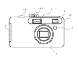
図1乃至図3は、本発明に係る撮像装置の例であるデジタルカメラの外観構成例を示しており、図1は正面図、図2は平面図、図3は背面図である。図1において、撮像装置の筐体であるカメラボディCBの正面には、ストロボ発光部3、光学ファインダ4の対物面、リモコン受光部6および撮像レンズを含む鏡胴ユニット7が配置されている。カメラボディCBの一方の側面部には、メモリカード装填室および電池装填室の蓋2が設けられている。
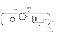
図2において、カメラボディCBの上面には、レリーズボタン(スイッチ)SW1、モードダイアルSW2およびサブ液晶ディスプレイ(サブLCD)(以下、「液晶ディスプレイ」を「LCD」と称する)1が配置されている。
1 to 3 show an example of the external configuration of a digital camera which is an example of an imaging apparatus according to the present invention. FIG. 1 is a front view, FIG. 2 is a plan view, and FIG. In FIG. 1, a
In FIG. 2, a release button (switch) SW1, a mode dial SW2, and a sub liquid crystal display (sub LCD) (hereinafter, “liquid crystal display” is referred to as “LCD”) 1 are disposed on the upper surface of the camera body CB. .
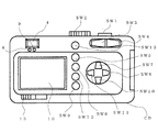
図3において、カメラボディCBの背面には、光学ファインダ4の接眼部、AF用発光ダイオード(以下、発光ダイオードは「LED」という)8、ストロボLED9、LCDモニタ10、電源スイッチ13、広角方向ズームスイッチSW3、望遠方向ズームスイッチSW4、セルフタイマの設定および解除スイッチSW5、メニュースイッチSW6、上移動およびストロボセットスイッチSW7、右移動スイッチSW8、ディスプレイスイッチSW9、下移動およびマクロスイッチSW10、左移動および画像確認スイッチSW11、OKスイッチSW12およびクイックアクセススイッチSW13が配置されている。
In FIG. 3, on the back of the camera body CB, there are an eyepiece part of the
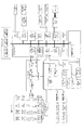
次に、図4に示す本発明に係る撮像装置の機能ブロックの例について説明する。本発明に係る撮像装置の各種動作(処理)は、ディジタル信号処理IC(集積回路)等として構成されるディジタルスティルカメラプロセッサ104(以下、単に「プロセッサ104」と称する)によって制御される。プロセッサ104は、第1のCCD(電荷結合素子)信号処理ブロック104−1,第2のCCD信号処理ブロック104−2,CPU(中央処理ユニット)ブロック104−3,ローカルSRAM(SRAM:スタティックランダムアクセスメモリ)104−4,USB(ユニバーサルシリアルバス)ブロック104−5,シリアルブロック104−6,JPEGコーデック(CODEC)ブロック104−7,リサイズ(RESIZE)ブロック104−8,TV信号表示ブロック104−9、およびメモリカードコントローラブロック104−10を有してなる。これら各ブロックは相互にバスラインで接続されている。 Next, an example of functional blocks of the imaging apparatus according to the present invention shown in FIG. 4 will be described. Various operations (processing) of the imaging apparatus according to the present invention are controlled by a digital still camera processor 104 (hereinafter simply referred to as “processor 104”) configured as a digital signal processing IC (integrated circuit) or the like. The processor 104 includes a first CCD (charge coupled device) signal processing block 104-1, a second CCD signal processing block 104-2, a CPU (central processing unit) block 104-3, a local SRAM (SRAM: static random access). Memory) 104-4, USB (Universal Serial Bus) block 104-5, serial block 104-6, JPEG codec (CODEC) block 104-7, resize block 104-8, TV signal display block 104-9, And a memory card controller block 104-10. These blocks are connected to each other via a bus line.
プロセッサ104の外部には、RAW−RGB画像データ、YUV画像データおよびJPEG画像データを保存するためのSDRAM(シンクロナスランダムアクセスメモリ)103、RAM107、内蔵メモリ120および制御プログラムが格納されたROM108が配置されており、これらはバスラインを介してプロセッサ104に接続されている。
Outside the processor 104, an SDRAM (synchronous random access memory) 103 for storing RAW-RGB image data, YUV image data, and JPEG image data, a
鏡胴ユニット7は、ズームレンズ7−1aを有するズーム光学系7−1,フォーカスレンズ7−2aを有するフォーカス光学系7−2,絞り7−3aを有する絞りユニット7−3およびメカニカルシャッタ7−4aを有するメカシャッタユニット7−4,を備えている。ズーム光学系7−1,フォーカス光学系7−2,絞りユニット7−3およびメカシャッタユニット7−4はそれぞれズーム(ZOOM)モータ7−1b、フォーカスレンズ移動手段としてのフォーカス(FOCUS)モータ7−2b、絞りモータ7−3bおよびメカシャッタモータ7−4bによって駆動される。これらZOOMモータ7−1b、FOCUSモータ7−2b、絞りモータ7−3bおよびメカシャッタモータ7−4bの各モータはモータドライバ7−5によって駆動され、モータドライバ7−5はプロセッサ104のCPUブロック104−3によって動作が制御される。
The
鏡胴ユニット7のズームレンズ7−1aおよびフォーカスレンズ7−2aは、撮像素子であるCCD101の撮像面上に被写体光学像を結像するための撮像レンズを構成する。CCD101は、前記被写体光学像を電気的な画像信号に変換してF/E−IC(フロントエンドIC)102に入力する。F/E−IC102は、CDS(相関2重サンプリング部)102−1、AGC(自動利得制御部)102−2およびA/D(アナログ−ディジタル)変換部102−3を有し、前記画像信号にそれぞれ所定の処理を施して、ディジタル信号に変換し、プロセッサ104の第1のCCD信号処理ブロック104−1に入力する。これらの信号処理動作は、プロセッサ104の第1のCCD信号処理ブロック104−1から出力されるVD・HD(垂直駆動・水平駆動)信号により、TG(タイミングジェネレータ)102−4を介して制御される。第1のCCD信号処理ブロック104−1は、CCD固体撮像素子101からF/E−IC102を経由して入力されたディジタル画像データに対してホワイトバランス調整およびγ調整等の信号処理を行うとともに、VD信号およびHD信号を出力する。
The zoom lens 7-1a and the focus lens 7-2a of the
プロセッサ104のCPUブロック104−3は、音声記録回路115−1による音声記録動作を制御する。音声記録回路115−1は、マイクロホン115−3で変換されマイクロホンアンプ115−2によって増幅した音声信号を、CPUブロック104−3の指令に応じて記録する。また、CPUブロック104−3は、音声再生回路116−1の動作も制御する。音声再生回路116−1は、CPUブロック104−3の指令により、適宜なるメモリに記録されている音声信号をオーディオアンプ116−2で増幅してスピーカー116−3に入力し、スピーカー116−3から音声を再生する。また、CPUブロック104−3は、ストロボ回路114を制御して動作させることによってストロボ発光部3から照明光を発光させる。また、CPUブロック104−3は、被写体距離を測定する測距ユニット5の動作も制御する。
The CPU block 104-3 of the processor 104 controls the sound recording operation by the sound recording circuit 115-1. The voice recording circuit 115-1 records the voice signal converted by the microphone 115-3 and amplified by the microphone amplifier 115-2 in accordance with a command from the CPU block 104-3. The CPU block 104-3 also controls the operation of the audio reproduction circuit 116-1. The audio reproduction circuit 116-1 amplifies an audio signal recorded in an appropriate memory by an audio amplifier 116-2 and inputs the audio signal to the speaker 116-3 in response to an instruction from the CPU block 104-3. Play audio. Further, the CPU block 104-3 controls the
なお、本発明に係る撮像装置は、後述するように、撮像された画像データに基づいてAF制御を行うものであるから、測距ユニット5による被写体距離の測定は必ずしも行う必要がなく、測距ユニット5を省いても良い。また、測距ユニット5を備えることにより、被写体距離の測定情報をストロボ回路114におけるストロボ発光制御に利用しても良い。測距ユニット5による被写体距離の測定情報を、撮像された画像データに基づく合焦制御に対して補助的に利用するようにしても良い。
Note that the imaging apparatus according to the present invention performs AF control based on captured image data, as will be described later. Therefore, it is not always necessary to measure the subject distance by the
さらに、CPUブロック104−3は、プロセッサ104の外部に配置されたサブCPU109にも結合されており、サブCPU109は、LCDドライバ111を介してサブLCD1による表示を制御する。また、サブCPU109は、AF用LED8,ストロボLED9,リモコン受光部6,上記スイッチSW1〜SW13からなる操作部およびブザー113にもそれぞれ結合されている。
Further, the CPU block 104-3 is also coupled to a
USBブロック104−5は、USBコネクタ122に結合されており、シリアルブロック104−6は、シリアルドライバ回路123−1を介してRS−232Cコネクタ123−2に結合されている。TV信号表示ブロック104−9は、LCDドライバ117を介してLCDモニタ10に結合されており、また、TV信号表示ブロック104−9は、ビデオアンプ118を介してビデオジャック119にも結合されている。メモリカードコントローラブロック104−10は、メモリカードスロット121のカード接点に結合されており、メモリカードがこのメモリカードスロット121に装填されると、メモリカードの接点に接触して電気的に接続される。
The USB block 104-5 is coupled to the USB connector 122, and the serial block 104-6 is coupled to the RS-232C connector 123-2 via the serial driver circuit 123-1. The TV signal display block 104-9 is coupled to the
次に、上述のように構成された撮像装置の動作について説明する。図1乃至図3に示すモードダイアルSW2を記録モードに設定することによって、撮像装置が記録モードで起動される。モードダイアルSW2による記録モードの設定は、図4における操作keyユニット(SW1〜SW13)に含まれるモードダイアルSW2の状態が記録モード−オンになったことをサブCPU109経由でCPUブロック104−3が検知することによって行われる。CPUブロック104−3はモータドライバ7−5を制御して、鏡胴ユニット7を撮像可能な位置に移動させる。さらに、CCD101、F/E−IC102およびLCDモニタ10等の各部に電源を投入して動作を開始させる。各部の電源が投入されると、ファインダモードの動作が開始される。
Next, the operation of the imaging apparatus configured as described above will be described. By setting the mode dial SW2 shown in FIGS. 1 to 3 to the recording mode, the imaging apparatus is activated in the recording mode. The recording mode setting by the mode dial SW2 is detected by the CPU block 104-3 via the
ファインダモードにおいては、鏡胴ユニット7の撮像レンズを通して撮像素子であるCCD101に入射した被写体からの光によってCCD101の受光面に被写体像が結ばれる。被写体像は、電気信号に変換されてRGBのアナログ信号としてCDS102−1に入力され、AGC(自動利得制御回路)102−2を介してA/D変換器102−3に送られる。A/D変換器102−3でディジタル信号に変換されたR、G、Bの各信号は、プロセッサ104内の第2のCCD信号処理ブロック104−2が具備するYUV変換手段でYUV画像データに変換され、フレームメモリとしてのSDRAM103に記録される。なお、第2のCCD信号処理ブロック104−2は、RGB画像データにフィルタリング処理等の適切な処理を施してYUV画像データに変換する。このYUV画像データは、CPUブロック104−3により読み出され、TV信号表示ブロック104−9を介してビデオアンプ118およびビデオジャック119を介してTV(テレビジョン)に送られ、あるいはLCDドライバ117を介してLCDモニタ10へ送られて表示に供される。この処理が1/30秒間隔で行われ、1/30秒毎に更新されるファインダモードでの表示となる。
In the finder mode, a subject image is formed on the light receiving surface of the
操作部のレリーズボタンSW1が押し下げられると、第1のCCD信号処理ブロック104−1に取り込まれたディジタルRGB画像データより、画面内の所定の少なくとも一部における合焦の度合いを示すAF評価値および露光状態を示すAE評価値が算出される。AF評価値は、特徴データとしてCPUブロック104−3に読み出されて、自動焦点検出手段による焦点検出処理(AF処理)に利用される。 When the release button SW1 of the operation unit is depressed, an AF evaluation value indicating the degree of focusing in a predetermined at least part of the screen from the digital RGB image data captured in the first CCD signal processing block 104-1. An AE evaluation value indicating the exposure state is calculated. The AF evaluation value is read as feature data to the CPU block 104-3 and used for focus detection processing (AF processing) by the automatic focus detection means.
合焦状態にある被写体は、そのエッジ部分が鮮明であるため、当該画像データに含まれる空間周波数の高周波成分が最も高くなる。被写体の画像データを用いて算出するAF評価値は、例えば変位量に対する微分値のように、高周波成分の高さを反映した値となるように設定されるため、このAF評価値が極大値となる画像データを取得したフォーカスレンズ7−2aの位置が合焦位置となる。すなわち、AF評価値からそのピーク位置を検出することで合焦位置を特定することができる。また、AF評価値の極大点が複数あらわれることも考慮に入れ、複数の極大点があった場合には、ピーク位置におけるAF評価値の大きさおよびその周辺位置のAF評価値の下降または上昇の度合いなども考慮し、最も信頼性があると推定される極大点を合焦位置とするAF処理を行う。 Since the edge of the subject in focus is clear, the high frequency component of the spatial frequency included in the image data is the highest. The AF evaluation value calculated using the image data of the subject is set to be a value that reflects the height of the high-frequency component, for example, a differential value with respect to the displacement amount. Therefore, this AF evaluation value is a maximum value. The position of the focus lens 7-2a that acquired the image data becomes the in-focus position. That is, the focus position can be specified by detecting the peak position from the AF evaluation value. Also, taking into consideration that a plurality of maximal points of the AF evaluation value appear, when there are a plurality of maximal points, the magnitude of the AF evaluation value at the peak position and the decrease or increase of the AF evaluation value at the peripheral position Considering the degree and the like, AF processing is performed with the maximum point estimated to be most reliable as the in-focus position.
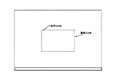
AF評価値は、ディジタルRGB画像データ内の特定の範囲(AF処理エリア)から算出することができる。図5はファインダモード時に前記LCDモニタ10に表示される画像面を示している。図5において、LCDモニタ10の中心部に表示されている枠内が当該撮像装置におけるAF処理エリアである。このAF処理エリアの例では、例えばRGB画像データの画面内の中央の水平方向の40%および垂直方向の30%の範囲を設定している。
The AF evaluation value can be calculated from a specific range (AF processing area) in the digital RGB image data. FIG. 5 shows an image plane displayed on the
次に、AF処理時におけるフォーカスレンズ7−2aの駆動タイミングとAF評価値の取得タイミングの関係について説明する。フォーカスレンズ7−2aの駆動は1回のVD信号に対応して所定のフォーカス駆動量によって行う。フォーカス駆動量は、例えばフォーカスモータ7−2bがパルスモータである場合は、駆動パルス数がそれに相当する。VD信号パルスの立下りに対応して所定のパルスレートで所定の駆動パルス数だけフォーカスレンズ7−2aを駆動することで1回のフォーカスレンズ駆動は終了する。次に出力されるVD信号パルスの立下りに対応して再度、所定のフォーカス駆動を行なう。このようにフォーカス駆動をVD信号(すなわちフレーム周期)に同期させて行う。 Next, the relationship between the drive timing of the focus lens 7-2a and the AF evaluation value acquisition timing during AF processing will be described. The focus lens 7-2a is driven by a predetermined focus drive amount corresponding to one VD signal. For example, when the focus motor 7-2b is a pulse motor, the number of drive pulses corresponds to the focus drive amount. By driving the focus lens 7-2a for a predetermined number of drive pulses at a predetermined pulse rate corresponding to the falling edge of the VD signal pulse, one focus lens drive is completed. A predetermined focus drive is performed again in response to the fall of the VD signal pulse to be output next. In this way, the focus drive is performed in synchronization with the VD signal (that is, the frame period).
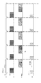
図20は、30fpsのフレームレートで画像データの取り込みを行う場合の、VD信号とフォーカスレンズ7−2aのフォーカス駆動タイミング、電子シャッタにおける電荷掃き出しパルス(SUB)のタイミング、及び露光タイミングを示すタイミングチャートである。図20において、1つのVD信号が発生すると(図20(a)参照)、それをトリガーとしてフォーカスレンズ7−2aを駆動するパルスが2つ生成され(図20(d)参照)、この2つの駆動パルスに対応した駆動量だけフォーカスレンズ7−2aが駆動されて移動する。また、VD信号をトリガーとして電荷掃き出しパルス(SUB)が所定数発生し(図20(b)参照)、SUBの数に応じて、CCD101に帯電している電荷の掃き出し処理を行なう。また、前記電荷掃き出し処理が終了した後に露光処理が行なわれる(図20(c)参照)。露光処理によって、被写体の映像を画像データとして取り込み、この画像データを用いて演算することによりAF評価値を取得する。上記駆動パルス数は可変であって、焦点距離や、フォーカスレンズ繰り出し量(フォーカス駆動範囲)などに応じて変化する。このように、本実施例におけるAF処理は、VD信号に同期してフォーカスレンズ7−2aの駆動範囲内において行うようになっている。
FIG. 20 is a timing chart showing the VD signal, the focus drive timing of the focus lens 7-2a, the charge sweep pulse (SUB) timing in the electronic shutter, and the exposure timing when capturing image data at a frame rate of 30 fps. It is. In FIG. 20, when one VD signal is generated (see FIG. 20A), two pulses are generated to drive the focus lens 7-2a using the VD signal as a trigger (see FIG. 20D). The focus lens 7-2a is driven and moved by a drive amount corresponding to the drive pulse. Further, a predetermined number of charge sweep pulses (SUB) are generated using the VD signal as a trigger (see FIG. 20B), and the charge sweeping process of the
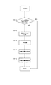
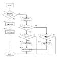
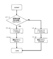
次に、本発明に係る撮像装置およびこの撮像装置による撮像方法の実施形態について説明する。まず、図6のフローチャートを用いて、レリーズボタンSW1が押下されたときのAF処理に関して説明する。レリーズボタンSW1が押下されたときのAF処理では、まずレリーズボタンSW1が押下されているかどうかを確認する(6−1)。レリーズボタンSW1が押下されている場合は開始スキャン処理(6−2)を行う。この処理の部分が本発明の一つの特徴になっているので、開始スキャン処理に関しては図7のフローチャートを用いてより具体的に説明する。 Next, an embodiment of an imaging apparatus according to the present invention and an imaging method using the imaging apparatus will be described. First, the AF process when the release button SW1 is pressed will be described using the flowchart of FIG. In the AF process when the release button SW1 is pressed, it is first checked whether or not the release button SW1 is pressed (6-1). When the release button SW1 is pressed, the start scan process (6-2) is performed. Since this process is one of the features of the present invention, the start scan process will be described more specifically with reference to the flowchart of FIG.
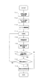
図7において、まず、仮開始位置設定処理を行う(7−1)。仮開始位置とはAF処理を開始する位置を決定する前段階の仮位置のことである。後のAF処理を行う際には、フォーカスレンズ7−2aの移動方向としてはバックラッシュの影響のない方向あるいはバックラッシュを除去する必要がない方向が好ましい。本実施例におけるフォーカスレンズ7−2aの移動方向は、近距離側から無限遠に向かう方向にあたるため、後のAF処理をする際のフォーカスレンズ7−2aの駆動方向は、近距離側→無限遠側方向としている。よって、仮開始位置は至近側におく必要があるため、本実施例では至近位置である30cm位置の被写体に合焦するフォーカスレンズ位置に設定している。 In FIG. 7, first, provisional start position setting processing is performed (7-1). The provisional start position is a provisional position in the previous stage for determining the position where the AF process is to be started. When performing the subsequent AF processing, the moving direction of the focus lens 7-2a is preferably a direction that is not affected by backlash or a direction that does not require removal of the backlash. Since the moving direction of the focus lens 7-2a in this embodiment is the direction from the short distance side toward infinity, the driving direction of the focus lens 7-2a during the later AF processing is the short distance side → infinity. Lateral direction. Therefore, since the temporary start position needs to be on the close side, in this embodiment, the focus lens position is set to focus on the subject at the 30 cm position which is the close position.
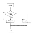
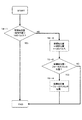
次に、フォーカス速度設定処理を行う(7−2)。フォーカス速度設定に関しては、開始スキャンに必要なAF評価値をとる間隔に応じて速度設定を行う。本実施例における撮像装置のファインダモードのフレームレートは30fpsのため、1/30[sec]間隔でAF評価値を取得する場合に対応したフォーカス速度を設定することになる。このフォーカス速度設定処理に関しては図8に示すとおりである。ここでは焦点距離に応じてそのフォーカス速度(パルスレート)を設定している。焦点距離が中間(Mean)未満か否かを判断し(8−1)、未満の場合は、パルスレートを100ppsと設定(8−2)し、それ以上の場合はパルスレートを500ppsと設定している(8−3)。このパルスレートの値に関しては、フォーカスレンズ位置がマクロ側にあれば、パルスレートを大きくするなど、フォーカスレンズ位置等に対応して可変するようにしておくことが望ましい。上記焦点距離を考慮しているのは、ズーム機能の搭載されたレンズを想定しているからである。単焦点の鏡胴ユニットの場合は、例えば100ppsで固定してもかまわない。本実施例では、上記中間(Mean)の位置は35mmフィルム換算で80mmを想定している。 Next, a focus speed setting process is performed (7-2). Regarding the focus speed setting, the speed is set according to the interval at which the AF evaluation value necessary for the start scan is taken. Since the frame rate of the finder mode of the image pickup apparatus in the present embodiment is 30 fps, a focus speed corresponding to the case where AF evaluation values are acquired at 1/30 [sec] intervals is set. The focus speed setting process is as shown in FIG. Here, the focus speed (pulse rate) is set according to the focal length. It is determined whether or not the focal length is less than the mean (8-1). If it is less, the pulse rate is set to 100 pps (8-2), and if it is more than that, the pulse rate is set to 500 pps. (8-3). Regarding the value of the pulse rate, if the focus lens position is on the macro side, it is desirable that the pulse rate be varied in accordance with the focus lens position, for example, by increasing the pulse rate. The focal length is taken into account because a lens with a zoom function is assumed. In the case of a single focus lens barrel unit, for example, it may be fixed at 100 pps. In the present embodiment, the intermediate position is assumed to be 80 mm in terms of 35 mm film.
図7に戻り、次に、フォーカス駆動を開始する(7−3)。フォーカス駆動開始後VD信号を待ち(7−4)、VD信号毎に映像信号を取得し、この映像信号に基づく画像データによって算出するAF評価値を取得する(7−5)。これにより、VD信号に同期させてフォーカスレンズを所定の向きに移動させ、AF評価値とフォーカス位置とを対応させることができるようにしておく。このようにして、フォーカス駆動開始位置が決定した際に、フォーカスレンズの移動する位置を特定することを可能にしている。 Returning to FIG. 7, next, focus drive is started (7-3). After the focus drive is started, a VD signal is waited (7-4), a video signal is acquired for each VD signal, and an AF evaluation value calculated from image data based on the video signal is acquired (7-5). Thus, the focus lens is moved in a predetermined direction in synchronization with the VD signal so that the AF evaluation value and the focus position can be associated with each other. In this way, when the focus drive start position is determined, it is possible to specify the position to which the focus lens moves.
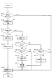
次に、開始位置判定処理を行う(7−6)。開始位置判定処理(7−6)の具体例について、図9のフローチャートを用いて説明する。まず、現在評価値と前回評価値の差分を求め、それが「0」以上かどうかを判断する(9−1)。「0」より上であった場合、評価値は上昇しているものと判断し、上昇フラグをオンにする(9−2)。また、そのときに下降カウントは「0」にしてリセットし(9−3)、開始位置判定処理を終了する。上記判断ステップで現在評価値と前回評価値の差分が「0」以下であった場合、評価値は下降しているものと判断し、下降カウントを増やす(9−4)。次に、上昇フラグがオンか否かを判断し(9−5)、オンだった場合、つまり評価値が上昇した後に下降している場合は、下降カウント数が「2」よりも大きい場合(9−6)にピークを検出したと判定し、ピーク検出フラグをオンにする(9−7)。上記上昇フラグ判断ステップで、上昇フラグがオンでない場合は、下降カウントが「4」よりも大きいか否かを判断し(9−9)、「4」よりも大きい場合、すでにピーク位置を行き過ぎているため単調下降状態となっていると判定し、単調下降フラグをオンにする(9−10)。上記ピーク検出フラグをオンにし、あるいは単調下降フラグをオンにしたのち、焦点検出動作開始位置決定処理を行う(9−8)。 Next, start position determination processing is performed (7-6). A specific example of the start position determination process (7-6) will be described with reference to the flowchart of FIG. First, a difference between the current evaluation value and the previous evaluation value is obtained, and it is determined whether or not it is “0” or more (9-1). If it is above “0”, it is determined that the evaluation value is rising, and the rising flag is turned on (9-2). At that time, the descent count is reset to “0” (9-3), and the start position determination process is terminated. When the difference between the current evaluation value and the previous evaluation value is “0” or less in the determination step, it is determined that the evaluation value is decreasing and the decrease count is increased (9-4). Next, it is determined whether or not the increase flag is on (9-5). If the increase flag is on, that is, if the evaluation value decreases after increasing, the decrease count is greater than “2” ( In 9-6), it is determined that the peak is detected, and the peak detection flag is turned on (9-7). If the rising flag is not on in the rising flag determining step, it is determined whether or not the falling count is larger than “4” (9-9). If it is larger than “4”, the peak position has already been exceeded. Therefore, it is determined that the state is in a monotonous descending state, and the monotonous descending flag is turned on (9-10). After the peak detection flag is turned on or the monotonic descent flag is turned on, focus detection operation start position determination processing is performed (9-8).
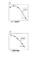
焦点検出動作開始位置の決定に関しては、ピーク検出であった場合に、現在位置より「1」評価値手前の位置、単調下降で合った場合は「2」評価値手前の位置を設定する。図13がそのときのAF評価値の波形である。図13(a)はピーク検出時の、図13(b)は単調下降時の波形である。黒丸で示す評価値に対して、白丸で示す位置が設定する開始位置となる。開始スキャン時に関しては、バックラッシュの影響を受ける方向であるため、この開始スキャンにおいて合焦位置を決めてしまうことは、焦点検出の精度として問題が生じることが多い。そこで、開始スキャンではあくまで次の処理であるAF処理の開始位置を決定するだけにとどめ、AF処理を行うことで精度良く合焦させることができる点が本発明の特徴である。 Regarding the determination of the focus detection operation start position, when the peak detection is performed, a position “1” before the evaluation value from the current position is set, and if the position is monotonically lowered, a position “2” before the evaluation value is set. FIG. 13 shows the waveform of the AF evaluation value at that time. FIG. 13A shows a waveform at the time of peak detection, and FIG. 13B shows a waveform at the time of monotonous descent. For the evaluation value indicated by the black circle, the position indicated by the white circle is the start position to be set. Since the start scan is in a direction affected by backlash, determining the in-focus position in this start scan often causes a problem as the accuracy of focus detection. Therefore, the feature of the present invention is that in the start scan, only the start position of the AF process, which is the next process, is determined, and the AF process can be performed with high accuracy.
図7に戻り、前記開始位置判定処理(7−6)のあと、現在位置が仮開始位置に到達しているか否かの判定を行い(7−7)、現在位置がまだ仮開始位置に到達していない場合(7−7のYES)は、さらに開始位置判定処理に付し(7−8)、開始位置が決定している場合、つまりピークが検出されている、もしくは単調下降していると判定された場合は、開始位置移動処理(7−9)に入り開始スキャン処理を終了する。開始位置移動処理(7−9)では、処理開始時にまだフォーカスレンズ7−2aが移動中の場合は、停止動作を行い、再度開始位置に向けて移動を開始し、そうでない場合はそのまま開始位置移動を開始する。開始位置が決定していない場合(7−8のNO)は、VD信号を再度待ち、AF評価値を取得し、開始位置判定処理を繰り返す。また、上記ステップ(7−7)において、フォーカスレンズ7−2aが仮開始位置まで移動している場合(7−7のNO)、開始位置移動処理(7−9)では、仮開始位置を開始位置と設定し、開始スキャン処理を終了する。以上が本発明で特徴とする開始スキャン処理である。 Returning to FIG. 7, after the start position determination process (7-6), it is determined whether or not the current position has reached the temporary start position (7-7), and the current position still reaches the temporary start position. If not (YES in 7-7), it is further subjected to a start position determination process (7-8). If the start position is determined, that is, a peak is detected or monotonically descends. Is determined, the start position movement process (7-9) is entered, and the start scan process ends. In the start position movement process (7-9), if the focus lens 7-2a is still moving at the start of the process, a stop operation is performed, and the movement is started again toward the start position. Otherwise, the start position is left as it is. Start moving. If the start position has not been determined (NO in 7-8), the process waits for the VD signal again, acquires the AF evaluation value, and repeats the start position determination process. If the focus lens 7-2a has moved to the temporary start position in step (7-7) (NO in 7-7), the temporary start position is started in the start position movement process (7-9). The position is set and the start scanning process is terminated. The above is the start scan process characterized by the present invention.
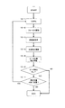
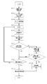
以上の処理を行った後、図6に示すフローのAF処理に入る(6−3)。AF処理の具体例を図10に示す。図10において、まず、VD信号の立ち下がりを検出するまで待つ(10−1)。VD信号の立ち下がりを検出した後に、所定パルス数に応じてフォーカスモータ7−2bを駆動し、フォーカスレンズ7−2aを移動させる(10−2)。フォーカスレンズ7−2aを移動させた後に映像信号を取得し、この映像信号に基づく画像データによってAF評価値を取得する(10−3)。このAF評価値より平滑微分演算処理(10−4)を行う。AF評価値の平滑微分演算処理については、移動するフォーカスレンズ7−2aから所定のタイミングで取り込まれた被写体の画像データを元に取得したAF評価値をX[0]とし、X[0]よりもa個前に取得されたAF評価値をX[−a]、X[0]よりもa個後に取得されたAF評価値をX[a]とし、各AF評価値に対する重み係数をb1、b2・・とした場合、平滑微分値Y[0]は、Y[0]=Σ[i=0→a](X[i]−X[−i])×biによって求めることができる。 After performing the above processing, the flow enters the AF processing shown in FIG. 6 (6-3). A specific example of the AF process is shown in FIG. In FIG. 10, first, the process waits until the falling edge of the VD signal is detected (10-1). After detecting the fall of the VD signal, the focus motor 7-2b is driven according to a predetermined number of pulses, and the focus lens 7-2a is moved (10-2). After moving the focus lens 7-2a, a video signal is acquired, and an AF evaluation value is acquired from image data based on this video signal (10-3). Smooth differentiation calculation processing (10-4) is performed from this AF evaluation value. As for the smooth differential calculation processing of the AF evaluation value, the AF evaluation value acquired based on the image data of the subject captured at a predetermined timing from the moving focus lens 7-2a is X [0], and X [0] Also, the AF evaluation value acquired before a is X [−a], the AF evaluation value acquired after a after X [0] is X [a], and the weight coefficient for each AF evaluation value is b1, In the case of b2..., the smooth differential value Y [0] can be obtained by Y [0] = Σ [i = 0 → a] (X [i] −X [−i]) × bi.
上記平滑微分演算式の具体例を示す。現在のAF評価値(X[0])の前後3評価値を用いて平滑微分値Y[0]を求める場合、
Y[0]=(X[−1]−X[1])×1+(X[−2]−X[2])×2
+(X[−3]−X[3])×3
となる。ここで、重み係数(bi=1,2,3・・・)は、現在のAF評価値X[0]に近いAF評価値(例えばX[1])を小さい係数とし、遠いAF評価値(例えばX[3])をより大きい係数とする。すなわち、現在値(X[0])との相関度合いが小さいものほど大きな値であればよい。具体的な係数値は上記の例に限るものではない。
A specific example of the smooth differential equation will be shown. When obtaining a smooth differential value Y [0] using three evaluation values before and after the current AF evaluation value (X [0]),
Y [0] = (X [−1] −X [1]) × 1 + (X [−2] −X [2]) × 2
+ (X [−3] −X [3]) × 3
It becomes. Here, the weighting coefficient (bi = 1, 2, 3...) Is a distant AF evaluation value (for example, X [1]) close to the current AF evaluation value X [0]. For example, let X [3]) be a larger coefficient. That is, the smaller the degree of correlation with the current value (X [0]), the larger the value. The specific coefficient value is not limited to the above example.
このようにフォーカスレンズ7−2aの移動に対応して取得するAF評価値の相関性を踏まえて上記の平滑微分値を求めることでAF評価値の極値を特定し、合焦位置を検出する。上記の演算式は前後3個のAF評価値を用いて平滑微分演算をするものであるが、演算に用いるAF評価値の個数はこれに限るものではない。 As described above, the extreme value of the AF evaluation value is specified by obtaining the above smooth differential value based on the correlation of the AF evaluation value acquired corresponding to the movement of the focus lens 7-2a, and the in-focus position is detected. . The above arithmetic expression performs a smooth differential calculation using three AF evaluation values before and after, but the number of AF evaluation values used for the calculation is not limited to this.
平滑微分値を求めるには複数個のAF評価値が必要となるため、AF処理の開始直後やフォーカスレンズ7−2aの駆動終了範囲直前のAF評価値取得タイミングでは、平滑微分演算を行なうことができない。従って、AF処理を開始してから平滑微分演算を開始できる個数のAF評価値を得るまで待ってから平滑微分演算処理を行なう。または、平滑微分演算処理に必要なAF評価値を、既に取得済のAF評価値を用いて推測し補間することで平滑微分演算処理を行う。 Since a plurality of AF evaluation values are required to obtain a smooth differential value, a smooth differential calculation can be performed immediately after the start of AF processing or at the AF evaluation value acquisition timing immediately before the driving end range of the focus lens 7-2a. Can not. Accordingly, after the AF processing is started, the smooth differentiation operation processing is performed after waiting until obtaining AF evaluation values of a number that can start the smooth differentiation operation. Alternatively, the smooth differential calculation process is performed by estimating and interpolating the AF evaluation value necessary for the smooth differential calculation process using the already acquired AF evaluation value.
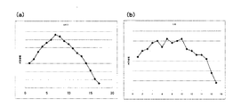
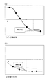
上記のAF処理において、VD信号に同期して取得されるAF評価値と、AF評価値を元にして算出される平滑微分値の例を図11,12に示す。図11はAF処理においてAF評価値の変位を示したものであり、縦軸はAF評価値の大きさを表わし、横軸はフォーカスレンズ7−2aの位置を示している。図11(a)は被写体輝度がLV10の場合であり、図11(b)はLV8の場合である。すなわち、図11(b)は、図11(a)よりも光量が少ない(暗い)環境で取得されたAF評価値に関するものである。従って、図11(b)に示す例では、隣接画素間の輝度差が微小であるため雑音の影響が大きく、AF評価値にバラツキが生じて複数のピーク位置が現われている。AF評価値のピーク位置(極大値)が図11(a)に示すように1カ所であれば、そこを合焦位置として設定すればよいが、図11(b)に示すように複数のピーク位置がある場合、どの位置を合焦位置とするかは単純に判定することはできない。 FIGS. 11 and 12 show examples of the AF evaluation value acquired in synchronization with the VD signal and the smooth differential value calculated based on the AF evaluation value in the AF processing described above. FIG. 11 shows the displacement of the AF evaluation value in the AF processing. The vertical axis represents the magnitude of the AF evaluation value, and the horizontal axis represents the position of the focus lens 7-2a. FIG. 11A shows the case where the subject brightness is LV10, and FIG. 11B shows the case where LV8. That is, FIG. 11B relates to an AF evaluation value acquired in an environment where the amount of light is smaller (darker) than in FIG. Therefore, in the example shown in FIG. 11B, since the luminance difference between adjacent pixels is small, the influence of noise is large, and the AF evaluation value varies and a plurality of peak positions appear. If the peak position (maximum value) of the AF evaluation value is one as shown in FIG. 11A, it may be set as the in-focus position, but a plurality of peaks as shown in FIG. If there is a position, it cannot be simply determined which position is the in-focus position.
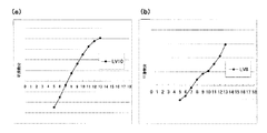
図12は、図11で示したAF評価値の平滑微分値を示したグラフである。図12において横軸は図11と同様にフォーカスレンズ7−2aの位置を示し、縦軸は平滑微分値の大きさを示す。図12(a)は図11(a)に示したAF評価値の変位を元にした平滑微分値を示す。図12(b)は図11(b)に示したAF評価値の変位を元にした平滑微分値を示す。図12(a)及び図12(b)に示すとおり、所定数のAF評価値が取得されるまでは平滑微分値は算出されない。所定数のAF評価値が取得された後に算出される平滑微分値は、フォーカスレンズ7−2aの移動に伴って変位し、ある点で符号が反転する。この反転する点がAF評価値の極大値に相当する。すなわち、先に示した演算式によって算出された平滑微分値の符号が反転する位置、すなわち平滑微分値がゼロの位置がAF評価値の極大点となる。このように、平滑微分値の符号が反転するAF評価値の取得位置を特定することで、合焦位置にフォーカスレンズ7―2aを移動させるAF処理を行うことができる。 FIG. 12 is a graph showing the smooth differential value of the AF evaluation value shown in FIG. In FIG. 12, the horizontal axis indicates the position of the focus lens 7-2a as in FIG. 11, and the vertical axis indicates the magnitude of the smooth differential value. FIG. 12A shows a smooth differential value based on the displacement of the AF evaluation value shown in FIG. FIG. 12B shows a smooth differential value based on the displacement of the AF evaluation value shown in FIG. As shown in FIGS. 12A and 12B, the smooth differential value is not calculated until a predetermined number of AF evaluation values are acquired. The smooth differential value calculated after the predetermined number of AF evaluation values are acquired is displaced with the movement of the focus lens 7-2a, and the sign is inverted at a certain point. This inversion point corresponds to the maximum value of the AF evaluation value. That is, the position where the sign of the smooth differential value calculated by the above-described arithmetic expression is inverted, that is, the position where the smooth differential value is zero is the maximum point of the AF evaluation value. In this manner, by specifying the acquisition position of the AF evaluation value at which the sign of the smooth differential value is inverted, the AF process for moving the focus lens 7-2a to the in-focus position can be performed.
図10において、平滑微分演算値より、ピーク位置検出処理を行う(10−5)。これは上記平滑微分値の符号が反転する点を検出する処理である。ピーク位置検出処理においてピークが検出されたか否かの判断を行い(10−6)、ピーク検出がされていない場合(10−6のYES)は、さらに現在のフォーカスレンズ7−2aの位置が終了位置まで達しているか否かの判定を行い(10−7)、達していない場合(10−7のYES)は、VD信号待ち(10−1)まで戻り、再度検出を行う。一方、現在のフォーカスレンズ7−2aの位置が終了位置まで達している場合(10−7のNO)は、AF処理を終了する。上記ピーク位置検出処理においてピーク検出がされている場合(10−6のNO)はAF処理を終了する。 In FIG. 10, peak position detection processing is performed from the smooth differential calculation value (10-5). This is a process for detecting a point where the sign of the smooth differential value is inverted. It is determined whether or not a peak is detected in the peak position detection process (10-6). If no peak is detected (YES in 10-6), the current position of the focus lens 7-2a is further terminated. It is determined whether or not the position has been reached (10-7). If the position has not been reached (YES in 10-7), the process returns to waiting for the VD signal (10-1) and detection is performed again. On the other hand, when the current position of the focus lens 7-2a has reached the end position (NO in 10-7), the AF process is ended. If the peak is detected in the peak position detection process (NO in 10-6), the AF process is terminated.
図6に戻り、AF処理(6−3)後、合焦位置決定処理を行う(6−4)。ここではAF処理においてピークが検出されている場合は、そのピーク位置を合焦位置と決定し、また検出できなかった場合はAFNGとして、NG位置を合焦位置と決定する。ここでのNG位置はおよそ2.5m程度離れた被写体に合焦するフォーカスレンズ7−2aの位置としている。最後に、フォーカスレンズを合焦位置へ移動させる処理を行う(6−5)。 Returning to FIG. 6, after the AF process (6-3), a focus position determination process is performed (6-4). Here, when a peak is detected in the AF process, the peak position is determined as the in-focus position, and when the peak position cannot be detected, the NG position is determined as the in-focus position as AFNG. The NG position here is the position of the focus lens 7-2a that focuses on a subject about 2.5 m away. Finally, a process of moving the focus lens to the in-focus position is performed (6-5).
以上説明した実施例1によれば、撮影レンズを焦点検出動作開始位置に向かって移動させている間にAF評価値を取得し、被写体状態を確認することで、その後のAF処理を高速化することが可能となる。特に鏡胴ユニットによっては、その駆動範囲が大きいものや、駆動源としてDCモータを使用したものなどがあるが、これらのものに対しても有効である。 According to the first embodiment described above, the AF evaluation value is acquired while the photographing lens is moved toward the focus detection operation start position, and the subject state is confirmed, thereby speeding up the subsequent AF processing. It becomes possible. In particular, some lens barrel units have a large driving range, and those using a DC motor as a driving source. These are also effective for these units.
次に、本発明に係る撮像装置およびこれを用いた撮像方法の第2の実施形態について説明する。レリーズボタンSW1が押下されたときのAF処理に関しては実施例1と同じである。図6において、レリーズボタンSW1が押下されたときのAF処理は、まず、レリーズボタンSW1が押下されているかどうかを確認するステップ(6−1)から始まる。レリーズボタンSW1が押下されている場合は開始スキャン処理を行う。この開始スキャン処理の部分が本実施例の特徴であり、図7に示すフローチャートを用いて既に説明したので、説明は省略する。次に、フォーカス速度設定処理を行う(7−2)。このフォーカス速度設定に関しても、図8に示すフローチャートを用いて既に説明したので、説明は省略する。 Next, a second embodiment of an imaging apparatus and an imaging method using the same according to the present invention will be described. The AF process when the release button SW1 is pressed is the same as in the first embodiment. In FIG. 6, the AF process when the release button SW1 is pressed starts with a step (6-1) for confirming whether or not the release button SW1 is pressed. When the release button SW1 is pressed, start scan processing is performed. This part of the start scanning process is a feature of this embodiment, and since it has already been described using the flowchart shown in FIG. Next, a focus speed setting process is performed (7-2). This focus speed setting has already been described with reference to the flowchart shown in FIG.
次に、フォーカス駆動を開始する(7−3)。フォーカス駆動開始後VD信号の出力を待ち(7−4)、VD信号が出力される毎に映像信号を取得し、この映像信号に基づく画像データによって算出するAF評価値を取得する(7−5)。これにより、VD信号に同期させてフォーカスレンズを所定の向きに移動させ、AF評価値とフォーカス位置の対応付けを行うことができるようにしておく。これにより、焦点検出動作開始位置が決定した際に、レンズを移動させる位置を特定することを可能にしている。 Next, focus drive is started (7-3). Waiting for the output of the VD signal after the focus driving is started (7-4), a video signal is acquired every time the VD signal is output, and an AF evaluation value calculated from image data based on the video signal is acquired (7-5). ). Accordingly, the focus lens is moved in a predetermined direction in synchronization with the VD signal so that the AF evaluation value and the focus position can be associated with each other. Thereby, when the focus detection operation start position is determined, it is possible to specify the position to move the lens.
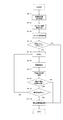
次に、開始位置判定処理を行う(7−6)。ここの部分が実施例2の特徴部分である。実施例2における開始位置判定処理(7−6)の具体例を図15に示す。図15において、まずAF評価値のカウント数が「2」より大きいかどうかを判断する(15−1)。これはその後の平滑微分演算の際に必要な評価値数が最低でも「3」は必要であるためである。評価値カウントが「3」に満たない場合(15−1のNO)は、評価値カウントに「1」を加えて終了する(15−6)。上記評価値カウントが「2」より大きい場合、平滑微分演算を行う(15−2)。平滑微分に関しては、実施例1で示したとおりである。次に、平滑微分値が「0」より上であるか否かを判断し(15−3)、「0」より上であった場合(15−3のYES)、平滑微分値は上昇しているものと判断して上昇フラグをオンにする(15−4)。また、そのときに下降カウントは「0」にしリセットする(15−5)。 Next, start position determination processing is performed (7-6). This part is a characteristic part of the second embodiment. A specific example of the start position determination process (7-6) in the second embodiment is shown in FIG. In FIG. 15, it is first determined whether or not the AF evaluation value count is greater than “2” (15-1). This is because “3” is necessary at least for the number of evaluation values required for the subsequent smooth differential calculation. When the evaluation value count is less than “3” (NO in 15-1), “1” is added to the evaluation value count and the process is ended (15-6). If the evaluation value count is greater than “2”, smooth differentiation is performed (15-2). The smooth differentiation is as described in the first embodiment. Next, it is determined whether or not the smooth differential value is above “0” (15-3). If it is above “0” (YES in 15-3), the smooth differential value increases. It is determined that the rising flag is turned on (15-4). At that time, the descent count is reset to "0" (15-5).
上記判断ステップで平滑微分値が「0」以下であった場合(15−3のNO)、下降カウントに「1」を加え(15−7)、次に上昇フラグがオンであるか否かを判断する(15−8)上昇フラグがオンの場合、下降カウント数を判断し(15−9)、下降カウントが「2」よりも大きい場合(15−9のYES)、ピーク検出フラグをオンにする(15−10)。このときの波形は図14(a)に示す例のようになり、ピークを検出したときの平滑微分値はプラスからマイナス側へ符号が反転している。上昇フラグがオンではない場合(15−8のNO)、下降カウントが「4」よりも大きいか否かを判断し(15−12)、下降カウントが「4」よりも大きい場合は(15−12のYES)、既に被写体への合焦位置を通りすぎてしまっていると判断し、遠側判定フラグをオンにする(15−13)。これは、図14(b)に示すように、被写体位置を過ぎてしまったあとの平滑微分値は常にマイナスであるという性質に基づいて判断するものである。ピーク検出フラグ、もしくは、遠側判定フラグがたっている場合は、開始位置決定処理を行う(15−11)。焦点検出動作開始位置の決定に関しては、ピーク検出であった場合に現在位置より「1」評価値手前の位置を設定し、遠側判定であった場合は「2」評価値手前の位置を設定する。実施例1との違いは、AF評価値ではなく平滑微分値を使用しているという点であり、それにより合焦位置にばらつきのない、高い精度でAF処理を行うことが可能である。 When the smooth differential value is not more than “0” in the above determination step (NO in 15-3), “1” is added to the decrease count (15-7), and then whether or not the increase flag is on is determined. Determine (15-8) If the rising flag is on, determine the number of descending counts (15-9). If the descending count is greater than “2” (YES in 15-9), turn on the peak detection flag. (15-10). The waveform at this time is similar to the example shown in FIG. 14A, and the sign of the smooth differential value when the peak is detected is inverted from the plus side to the minus side. When the rising flag is not on (NO in 15-8), it is determined whether or not the falling count is larger than “4” (15-12), and when the falling count is larger than “4” (15− 12), it is determined that the subject has already passed the in-focus position, and the far side determination flag is turned on (15-13). As shown in FIG. 14B, this is based on the property that the smooth differential value after passing the subject position is always negative. If the peak detection flag or the far side determination flag is set, start position determination processing is performed (15-11). Regarding the determination of the focus detection operation start position, the position before the evaluation value “1” is set from the current position when the peak is detected, and the position before the evaluation value “2” is set when the determination is the far side. To do. The difference from the first embodiment is that a smooth differential value is used instead of an AF evaluation value, so that it is possible to perform AF processing with high accuracy without variation in focus position.
図7に戻り、現在位置がまだ仮開始位置に到達していない状態(7−7のYES)で、開始位置判定処理にて開始位置が決定している場合(7−8のYES)、つまりピークが検出されている、もしくは遠側と判定できた場合は、開始位置移動処理(7−9)に入り終了する。開始位置移動処理(7−9)では、処理開始時にまだフォーカスレンズ7−2aが移動中の場合は、停止動作を行い、再度開始位置に向けて移動を開始し、そうでない場合はそのまま焦点検出動作開始位置移動を開始する。開始位置が決定していない場合(7−8のNO)は、VD信号を再度待ち、評価値を取得し開始位置判定処理を繰り返す。またフォーカスレンズ7−2aが仮開始位置まで移動している場合(7−7のNO)、開始位置移動処理(7−9)では、仮開始位置を開始位置と設定し、開始スキャン処理を終了する。
以上が、実施例2が特徴としている開始スキャン処理である。
Returning to FIG. 7, when the current position has not yet reached the temporary start position (YES in 7-7) and the start position is determined in the start position determination process (YES in 7-8), that is, If a peak has been detected or it can be determined that the peak is far, a start position moving process (7-9) is entered and the process ends. In the start position moving process (7-9), if the focus lens 7-2a is still moving at the start of the process, the stop operation is performed, and the movement is started again toward the start position. Otherwise, the focus detection is performed as it is. Start moving the movement start position. If the start position has not been determined (NO in 7-8), the process waits for the VD signal again, obtains an evaluation value, and repeats the start position determination process. When the focus lens 7-2a has moved to the temporary start position (NO in 7-7), in the start position movement process (7-9), the temporary start position is set as the start position, and the start scan process ends. To do.
The above is the start scan process characterized in the second embodiment.
上記開始スキャン処理が終了すると、続いてAF処理(6−3)、合焦位置決定処理(6−4)、そして合焦位置への移動処理を行い(6−5)、撮像装置による一連の自動焦点調節動作を終了する。上記AF処理(6−3)、合焦位置決定処理(6−4)、合焦位置への移動処理(6−5)の具体例は、実施例1について説明した処理と同じであるから、ここでは説明を省略する。 When the start scanning process is completed, an AF process (6-3), a focus position determination process (6-4), and a movement process to the focus position are performed (6-5). The auto focus adjustment operation ends. Specific examples of the AF process (6-3), the focus position determination process (6-4), and the movement process to the focus position (6-5) are the same as those described in the first embodiment. The description is omitted here.
次に本発明に係る撮像装置およびこれを用いた撮像方法の第3の実施形態について説明する。レリーズボタンSW1が押下されたときのAF処理に関しては実施例2と同じである。図6において、レリーズボタンSW1が押下されたときのAF処理は、まずレリーズボタンSW1が押下されているかどうかを確認するステップ(6−1)から始まる。レリーズボタンSW1が押下されている場合は開始スキャン処理を行う(6−2)。この処理の部分が本実施例の特徴でもある。開始スキャン処理に関しては図16のフローチャートを用いて説明する。 Next, a description will be given of a third embodiment of an imaging apparatus and an imaging method using the same according to the present invention. The AF process when the release button SW1 is pressed is the same as in the second embodiment. In FIG. 6, the AF process when the release button SW1 is pressed starts with a step (6-1) for confirming whether or not the release button SW1 is pressed. If the release button SW1 is pressed, start scan processing is performed (6-2). This part of processing is also a feature of this embodiment. The start scan process will be described with reference to the flowchart of FIG.
図16において、まず、仮開始位置設定処理を行う(16−1)。仮開始位置とはAF処理を開始する位置を決定する前段階の仮位置のことである。後のAF処理を行う際には、フォーカスレンズ7−2aの移動方向としてはバックラッシュの影響のない方向あるいはバックラッシュを除去する必要がない方向が好ましい。本実施例におけるフォーカスレンズ7−2aの移動方向は、近距離側から無限遠に向かう方向にあたるため、後のAF処理をする際のフォーカスレンズ7−2aの駆動方向は、近距離側→無限遠側方向としている。よって、仮開始位置は至近側におく必要があるため、本実施例では至近位置である30cm位置に相当するフォーカスレンズ位置に設定している。 In FIG. 16, first, provisional start position setting processing is performed (16-1). The provisional start position is a provisional position in the previous stage for determining the position where the AF process is to be started. When performing the subsequent AF processing, the moving direction of the focus lens 7-2a is preferably a direction that is not affected by backlash or a direction that does not require removal of the backlash. Since the moving direction of the focus lens 7-2a in this embodiment is the direction from the short distance side toward infinity, the driving direction of the focus lens 7-2a during the later AF processing is the short distance side → infinity. Lateral direction. Therefore, since the temporary start position needs to be on the close side, the focus lens position corresponding to the 30 cm position which is the close position is set in this embodiment.
次に、フォーカス速度設定処理を行う(16−2)。フォーカス速度設定に関しては、開始スキャンに必要なAF評価値をとる間隔により速度設定を行う。この速度設定時に、仮開始位置と現在位置とのフォーカスレンズ7−2aの移動範囲ないしは移動量を確認し、速度設定ならびにその後の開始スキャンを実施するかどうかの判断を行う部分が本実施例の特徴とする部分である。これに関しては図17のフローチャートを使用して説明する。 Next, a focus speed setting process is performed (16-2). Concerning the focus speed setting, the speed is set by an interval at which an AF evaluation value necessary for the start scan is taken. In this embodiment, the speed range and the moving amount of the focus lens 7-2a between the temporary start position and the current position are confirmed at this speed setting, and the speed setting and the determination of whether or not to perform the subsequent start scan are performed. It is a characteristic part. This will be described with reference to the flowchart of FIG.
図17において、まず仮開始位置から現在フォーカスレンズ位置までの差分を確認する(17−1)。この差分が例えば100パルスより離れている場合(17−1のYES)は、パルスレートを100pps(17−3)とし、開始スキャンフラグをオンする(17−3)。上記差分が100パルス以下であった場合(17−1のNO)は、パルスレートを1000pps(17−4)として、開始スキャンフラグをオフとする(17−5)。この処理において、仮開始位置までの差分が所定以上ある場合は(17−1のYES)、パルスレートを落としてAF評価値を取得し開始スキャンを行いAF処理時の開始位置を決定し、上記差分が所定以上ない場合(17−1のNO)は、AF評価値数が少なく開始スキャンをする意味がないため、開始スキャンを行わず、高速パルスレートで仮開始位置まで移動してしまう、ということが本実施例の特徴とするところである。開始スキャンを行う場合は100ppsとしているが、これに関しては実施例1、実施例2と同様に焦点距離に応じて、または撮影モードに合わせて可変することができればさらに良い。また開始スキャンを行わない場合の高速パルスレートの設定に関しても1000ppsに限ったことではなく、可変できることが望ましい。 In FIG. 17, first, the difference from the temporary start position to the current focus lens position is confirmed (17-1). For example, if the difference is more than 100 pulses (YES in 17-1), the pulse rate is set to 100 pps (17-3) and the start scan flag is turned on (17-3). When the difference is 100 pulses or less (NO in 17-1), the pulse rate is set to 1000 pps (17-4) and the start scan flag is turned off (17-5). In this process, when the difference to the temporary start position is greater than or equal to a predetermined value (YES in 17-1), the AF evaluation value is obtained by lowering the pulse rate and the start scan is performed to determine the start position during the AF process. If the difference is not greater than or equal to the predetermined value (NO in 17-1), the number of AF evaluation values is small and there is no point in performing the start scan, so the start scan is not performed and the movement to the temporary start position is performed at a high pulse rate. This is a feature of this embodiment. In the case of performing the start scan, it is set to 100 pps. However, in this regard, it is better if it can be changed in accordance with the focal length or in accordance with the photographing mode as in the first and second embodiments. In addition, the setting of the high-speed pulse rate when the start scan is not performed is not limited to 1000 pps, and is desirably variable.
図16に戻り、フォーカス速度設定処理のあと、フォーカス駆動を開始する(16−3)。フォーカス駆動開始後、開始スキャンフラグがオンの場合(16−4のYES)は、VD信号を待ち(16−5)、VD信号毎に映像信号を取得し、この映像信号に基づく画像データによって算出するAF評価値を取得(16−6)する。このときのAF評価値とフォーカス位置に関しては対応付けを行うことができるようにしておくことで、焦点検出動作開始位置が決定した際に、フォーカスレンズを移動させる位置を特定することが可能となる。開始スキャンフラグがオフの場合(16−4のNO)、開始位置移動処理(16−10)へ移動する。このとき開始位置移動処理(16−10)では、仮開始位置設定処理(16−1)で設定されたレンズ位置を開始位置と設定し、開始スキャン処理を終了する。 Returning to FIG. 16, after the focus speed setting process, focus drive is started (16-3). If the start scan flag is on after the focus drive is started (YES in 16-4), it waits for the VD signal (16-5), obtains a video signal for each VD signal, and calculates by image data based on this video signal. The AF evaluation value to be acquired is acquired (16-6). By making it possible to associate the AF evaluation value and the focus position at this time, it is possible to specify the position to move the focus lens when the focus detection operation start position is determined. . If the start scan flag is OFF (NO in 16-4), the process moves to the start position movement process (16-10). At this time, in the start position movement process (16-10), the lens position set in the temporary start position setting process (16-1) is set as the start position, and the start scan process is ended.
上記AF評価値を取得(16−6)すると、次に、開始位置判定処理を行う(16−7)。開始位置判定処理(16−7)に関しては、実施例2について説明した図15に示すフローチャートの動作と同じであるから、ここでは説明を省略する。 When the AF evaluation value is acquired (16-6), next, start position determination processing is performed (16-7). Since the start position determination process (16-7) is the same as the operation of the flowchart shown in FIG. 15 described in the second embodiment, the description thereof is omitted here.
図16において、開始位置判定処理(16−7)のあと、現在位置が終了位置に到達しているか否かの判定を行い(16−4)、現在位置がまだ終了位置に到達していない状態(16−8YES)である場合、開始位置判定処理を行い(16−9)、この判定ステップで開始位置が決定している場合(16−9のYES)、つまりピークが検出されている、もしくは遠側と判定できた場合は、開始位置移動処理(16−10)に入り、終了する。開始位置移動処理(16−10)では、処理開始時にまだフォーカスレンズ7−2aが移動中の場合は、停止動作を行い、再度開始位置に向けて移動を開始し、そうでない場合はそのまま開始位置移動を開始する。開始位置が決定していない場合(16−9のNO)は、VD信号を再度待ち(16−5)、評価値を取得し開始位置判定処理を繰り返す。またフォーカスレンズ7−2aが終了位置まで移動している場合(16−8のNO)、開始位置移動処理(16−10)では、開始位置を終了位置、つまり仮開始位置設定処理(16−1)で設定されたレンズ位置を開始位置と設定し、開始スキャン処理を終了する。以上が開始スキャン処理の流れである。 In FIG. 16, after the start position determination process (16-7), it is determined whether or not the current position has reached the end position (16-4), and the current position has not yet reached the end position. If (16-8 YES), start position determination processing is performed (16-9), and if the start position is determined in this determination step (YES in 16-9), that is, a peak is detected, or If it is determined that the remote side has been determined, the start position moving process (16-10) is entered and the process ends. In the start position moving process (16-10), if the focus lens 7-2a is still moving at the start of the process, a stop operation is performed, and the movement is started again toward the start position. Start moving. If the start position has not been determined (NO in 16-9), the process waits for the VD signal again (16-5), obtains an evaluation value, and repeats the start position determination process. When the focus lens 7-2a has moved to the end position (NO in 16-8), in the start position movement process (16-10), the start position is set as the end position, that is, the temporary start position setting process (16-1). ) Is set as the start position, and the start scan process is terminated. The above is the flow of the start scan process.
図16に示す開始スキャン処理(図6におけるステップ6−2)が終了すると、図6に示すAF処理に入る(6−3)。AF処理の具体例は、すでに説明した図10に示すフローチャートの動作と同じである。すなわち、まず、VD信号の立ち下がりを検出するまでVD信号待ち処理を行う(10−1)。VD信号の立ち下がりを検出した後に、所定パルス数に応じてフォーカスモータ7−2bを駆動し、フォーカスレンズ7−2aを移動する(10−2)。フォーカスレンズ7−2aを移動した後に映像信号を取得し、この映像信号に基づく画像データによってAF評価値を算出する(10−3)。次にAF評価値より平滑微分演算処理(10−4)を行う。AF評価値の平滑微分演算処理については、実施例1について説明した演算処理と同じである。 When the start scan process (step 6-2 in FIG. 6) shown in FIG. 16 is completed, the AF process shown in FIG. 6 is started (6-3). A specific example of the AF processing is the same as the operation of the flowchart shown in FIG. 10 already described. That is, first, a VD signal wait process is performed until the falling edge of the VD signal is detected (10-1). After detecting the fall of the VD signal, the focus motor 7-2b is driven according to the predetermined number of pulses, and the focus lens 7-2a is moved (10-2). After moving the focus lens 7-2a, a video signal is acquired, and an AF evaluation value is calculated from image data based on this video signal (10-3). Next, smooth differentiation calculation processing (10-4) is performed from the AF evaluation value. The AF evaluation value smooth differential calculation process is the same as the calculation process described in the first embodiment.
平滑微分演算値より、ピーク位置検出処理を行う(10−5)。これは上記平滑微分値の符号が反転する点を検出する処理である。ピーク位置検出処理にてピーク検出がされておらず(10−6のYES)、かつ、現在のフォーカスレンズ7−2aの位置が終了位置まで達していない場合(10−7のYES)は、VD信号待ちのステップ(10−1)まで戻り、再度検出を行う。一方、現在のフォーカスレンズ7−2aの位置が終了位置まで達している場合(10−7のNO)は、AF処理を終了する。ピーク位置検出処理(10−6)にてピーク検出がされている場合(10−6のNO)はAF処理を終了する。 Peak position detection processing is performed from the smooth differential calculation value (10-5). This is a process for detecting a point where the sign of the smooth differential value is inverted. If no peak is detected in the peak position detection process (YES at 10-6) and the current position of the focus lens 7-2a has not reached the end position (YES at 10-7), VD The process returns to the signal waiting step (10-1), and detection is performed again. On the other hand, when the current position of the focus lens 7-2a has reached the end position (NO in 10-7), the AF process is ended. If the peak is detected in the peak position detection process (10-6) (NO in 10-6), the AF process is terminated.
図6に戻り、続いて合焦位置決定処理を行う(6−4)。ここではAF処理にてピーク検出されている場合は、そのピーク位置を合焦位置と決定し、また検出できなかった場合はAFNGとして、NG位置を合焦位置と決定する。ここでのNG位置はおよそ2.5m程度離れた被写体に合焦するフォーカスレンズ7−2aの位置としている。最後に、合焦位置へ移動する処理を行う(6−5)。 Returning to FIG. 6, the focus position determination process is subsequently performed (6-4). Here, when the peak is detected by the AF process, the peak position is determined as the in-focus position, and when the peak position cannot be detected, the NG position is determined as the in-focus position as AFNG. The NG position here is the position of the focus lens 7-2a that focuses on a subject about 2.5 m away. Finally, a process of moving to the in-focus position is performed (6-5).
次に、本発明に係る撮像装置およびこれを用いた撮像方法の第4の実施形態について説明する。レリーズボタンSW1が押下されたときのAF処理に関してはこれまで説明してきた各実施例と同じである。図6において、レリーズボタンSW1が押下されることによって行われる開始スキャン処理の部分はこの実施例の特徴部分ある。開始スキャン処理に関しては図18のフローチャートを用いて説明する。 Next, a description will be given of a fourth embodiment of an imaging apparatus and an imaging method using the same according to the present invention. The AF process when the release button SW1 is pressed is the same as in the embodiments described so far. In FIG. 6, the part of the start scanning process performed by pressing the release button SW1 is a characteristic part of this embodiment. The start scan process will be described with reference to the flowchart of FIG.
図18において、まず、仮開始位置設定処理を行う(18−1)。仮開始位置とはAF処理を開始する位置を決定する前段階の仮位置のことである。後のAF処理を行う際には、フォーカスレンズ7−2aの移動方向としてはバックラッシュの影響のない方向あるいはバックラッシュを除去する必要がない方向が好ましい。本実施例におけるフォーカスレンズ7−2aの移動方向は、近距離側から無限遠に向かう方向にあたるため、後のAF処理をする際のフォーカスレンズ7−2aの駆動方向は、近距離側→無限遠側方向としている。よって、仮開始位置は至近側におく必要があるため、本実施例では至近位置である30cm位置に相当するフォーカスレンズ位置に設定している。 In FIG. 18, first, provisional start position setting processing is performed (18-1). The provisional start position is a provisional position in the previous stage for determining the position where the AF process is to be started. When performing the subsequent AF processing, the moving direction of the focus lens 7-2a is preferably a direction that is not affected by backlash or a direction that does not require removal of the backlash. Since the moving direction of the focus lens 7-2a in this embodiment is the direction from the short distance side toward infinity, the driving direction of the focus lens 7-2a during the later AF processing is the short distance side → infinity. Lateral direction. Therefore, since the temporary start position needs to be on the close side, the focus lens position corresponding to the 30 cm position which is the close position is set in this embodiment.
図19は本実施例における仮開始位置設定処理を示す。図19において、現在位置と仮開始位置との差分が100パルスより離れている場合(19−1のYES)は動作を終了し、それ以外の場合(19−1のNO)に関しては、現在位置+100パルスの位置を仮開始位置とする(19−2)。仮開始位置が最至近位置(以後「フォーカスリミッタ位置」と呼ぶ)を超えている場合(19−3のYES)に関しては、フォーカスリミッタ位置を仮開始位置として終了する(19−4)。仮開始位置がフォーカスリミッタ位置を超えていない場合(19−3のNo)は、仮開始位置をそのままにして終了する(19−4)。この仮開始位置設定処理に関しては、現在位置が至近位置である30cm付近にいる場合に関しては、開始スキャンの範囲が狭くなり、その分AF評価値の取得が困難になるということから、仮開始位置をマクロ域まで拡張して、開始スキャンを行うことを目的としている。これによって開始スキャン時に必要なAF評価値数を確保できるため、開始位置の決定を行うことが可能となる。上記ステップ19−1では、現在位置と仮開始位置との差分が100パルスより離れていることを前提としているが、これに関しては、焦点距離に応じて、あるいは撮像装置の仕様等によって可変する部分であるから、これに限定されるものではない。 FIG. 19 shows provisional start position setting processing in the present embodiment. In FIG. 19, when the difference between the current position and the temporary start position is more than 100 pulses (YES in 19-1), the operation ends, and in other cases (NO in 19-1), the current position The position of +100 pulse is set as a temporary start position (19-2). When the temporary start position exceeds the closest position (hereinafter referred to as “focus limiter position”) (YES in 19-3), the focus limiter position is ended as the temporary start position (19-4). If the temporary start position does not exceed the focus limiter position (No in 19-3), the temporary start position is left as it is (19-4). With regard to this temporary start position setting process, when the current position is in the vicinity of the closest position of 30 cm, the start scan range is narrowed, and acquisition of the AF evaluation value becomes difficult accordingly. The purpose of this is to start the scan by extending to the macro area. As a result, the number of AF evaluation values necessary for the start scan can be secured, so that the start position can be determined. In step 19-1, it is assumed that the difference between the current position and the provisional start position is more than 100 pulses, but this is a part that varies depending on the focal length or the specifications of the imaging device. Therefore, it is not limited to this.
次に、フォーカス速度設定処理を行う(18−2)。フォーカス速度は、開始スキャンに必要なAF評価値をとる間隔に応じて設定する。本実施例にかかる撮像装置のファインダモードのフレームレートは30fpsのため、1/30[sec]間隔でAF評価値を取得する場合に対応したフォーカス速度を設定することになる。この処理は図8に示すとおりで、前記実施例において説明した流れと同じであるから、ここでは説明を省略する。 Next, a focus speed setting process is performed (18-2). The focus speed is set according to the interval at which the AF evaluation value necessary for the start scan is taken. Since the frame rate of the finder mode of the imaging apparatus according to the present embodiment is 30 fps, a focus speed corresponding to the case where AF evaluation values are acquired at 1/30 [sec] intervals is set. This processing is as shown in FIG. 8 and is the same as the flow described in the above embodiment, and therefore the description thereof is omitted here.
次にフォーカス駆動を開始する(18−3)。フォーカス駆動開始後VD信号を待ち(18−4)、VD信号毎に映像信号を取得し、この映像信号に基づく画像データによって算出するAF評価値を取得(18−5)する。このときのAF評価値とフォーカス位置に関しては対応付けを行うことができるようにしておくことで、焦点検出動作開始位置が決定した際に移動する位置ないしは向きを特定することが可能となる。 Next, focus drive is started (18-3). After the focus driving is started, a VD signal is waited (18-4), a video signal is acquired for each VD signal, and an AF evaluation value calculated from image data based on the video signal is acquired (18-5). By making it possible to associate the AF evaluation value and the focus position at this time, it is possible to specify the position or direction of movement when the focus detection operation start position is determined.
次に、開始位置判定処理を行う(18−6)。ここの部分は前記実施例2における開始位置判定処理と同じであり、図15に示すフローチャートに沿って処理される。よって、ここでは開始位置判定処理の具体的な説明は省略する。 Next, start position determination processing is performed (18-6). This part is the same as the start position determination process in the second embodiment, and is processed according to the flowchart shown in FIG. Therefore, a specific description of the start position determination process is omitted here.
図18に戻り、現在位置がまだ終了位置に到達していない状態(18−7のYES)であり、かつ、開始位置決定処理(18−8)にて開始位置が決定している場合(18−8のYES)、つまりピークが検出されている、もしくは単調下降していると判定できる場合は、開始位置移動処理(18−9)を行って終了する。開始位置移動処理(18−9)では、処理開始時にまだフォーカスレンズ7−2aが移動中の場合は、停止動作を行い、再度開始位置に向けて移動を開始し、そうでない場合はそのまま開始位置移動を開始する。開始位置が決定していない場合(18−8のNO)は、VD信号を再度待ち、評価値を取得し開始位置判定処理を繰り返す。またフォーカスレンズ7−2aが仮開始位置まで移動している場合(18−7のNO)、現在位置+100パルスの位置を仮開始位置に再設定する(18−10)。 Returning to FIG. 18, when the current position has not yet reached the end position (YES in 18-7), and the start position is determined in the start position determination process (18-8) (18). -8), that is, when it can be determined that a peak is detected or monotonically descending, a start position moving process (18-9) is performed and the process is terminated. In the start position movement process (18-9), if the focus lens 7-2a is still moving at the start of the process, a stop operation is performed, and the movement is started again toward the start position. Start moving. When the start position has not been determined (NO in 18-8), the process waits for the VD signal again, obtains an evaluation value, and repeats the start position determination process. If the focus lens 7-2a has moved to the temporary start position (NO in 18-7), the current position + 100 pulse position is reset to the temporary start position (18-10).
仮開始位置がフォーカスリミッタ位置まで到達していなかった場合(18−11のNO)、開始位置が決定されているかどうかを判断するステップ(18−8)にいく。また仮開始位置がフォーカスリミッタ位置まで到達していたら(18−11のYES)、フォーカスリミッタ位置を開始位置に再設定し(18−12)、開始位置移動処理(18−9)に入る。このようにして、開始位置が決定するまで継続的に開始スキャンを行うこと、およびAF処理前に被写体環境を確認することが可能となる。開始位置移動処理(18−9)では、開始位置を終了位置、つまり仮開始位置設定処理(18−1)で設定されたレンズ位置を開始位置と設定し、開始スキャン処理を終了する。
以上が実施例4において特徴とする開始スキャン処理である。
If the temporary start position has not reached the focus limiter position (NO in 18-11), the process proceeds to step (18-8) for determining whether the start position has been determined. If the temporary start position has reached the focus limiter position (YES at 18-11), the focus limiter position is reset to the start position (18-12), and the start position movement process (18-9) is entered. In this way, it is possible to continuously perform the start scan until the start position is determined, and to confirm the subject environment before the AF process. In the start position moving process (18-9), the start position is set as the end position, that is, the lens position set in the temporary start position setting process (18-1) as the start position, and the start scan process is ended.
The above is the start scan process characterized in the fourth embodiment.
上記開始スキャン処理が終了すると、続いてAF処理(6−3)、合焦位置決定処理(6−4)、そして合焦位置への移動処理を行い(6−5)、撮像装置による一連の自動焦点調節動作を終了する。上記AF処理(6−3)、合焦位置決定処理(6−4)、合焦位置への移動処理(6−5)の具体例は、実施例1について説明した処理と同じであるから、ここでは説明を省略する。 When the start scanning process is completed, an AF process (6-3), a focus position determination process (6-4), and a movement process to the focus position are performed (6-5). The auto focus adjustment operation ends. Specific examples of the AF process (6-3), the focus position determination process (6-4), and the movement process to the focus position (6-5) are the same as those described in the first embodiment. The description is omitted here.
本発明に係る撮像装置および撮像方法は、デジタルカメラをはじめとして、携帯電話に組み込まれたカメラ、その他各種カメラに適用可能である。本発明に係る撮像装置および撮像方法によれば、自動合焦に要する時間を短縮することができるため、シャッタチャンスを逃がすことの少なくすることができる。 The imaging apparatus and imaging method according to the present invention can be applied to a digital camera, a camera incorporated in a mobile phone, and other various cameras. According to the imaging apparatus and the imaging method according to the present invention, the time required for automatic focusing can be shortened, so that it is possible to reduce the chance of missing a photo opportunity.
7 鏡胴ユニット
101 撮像素子(CCD)
104 ディジタルスティルカメラプロセッサ
7−2 フォーカスレンズ
7−2b フォーカスモータ
7−5 モータドライバ
7
104 Digital Still Camera Processor 7-2 Focus Lens 7-2b Focus Motor 7-5 Motor Driver
Claims (22)
上記自動焦点検出手段は、上記レンズ移動手段が上記撮像レンズを焦点検出動作開始位置に向かって駆動する際に上記画像データからAF評価値を取得し、
上記AF評価値に基づいて自動焦点検出の開始位置を決定する開始位置決定手段を備えること特徴とする撮像装置。 In an imaging apparatus having an imaging element that receives light from a subject that has passed through an imaging lens, a lens moving unit that moves the imaging lens, and an automatic focus detection unit that determines a focus based on image data obtained from the imaging element ,
The automatic focus detection unit acquires an AF evaluation value from the image data when the lens moving unit drives the imaging lens toward a focus detection operation start position;
An image pickup apparatus comprising start position determination means for determining a start position of automatic focus detection based on the AF evaluation value.
上記自動焦点検出工程は、レンズ移動手段が上記撮像レンズを焦点検出動作開始位置に向かって駆動する際に上記画像データからAF評価値を取得し、上記AF評価値に基づいて自動焦点検出の開始位置を決定する開始位置決定工程を持つことを特徴とする撮像方法。 An automatic focus detection step of receiving light of a subject that has passed through the imaging lens by the imaging device and determining a focus based on image data obtained from the imaging device, a lens moving step of moving the imaging lens toward the determined focal position In an imaging method comprising:
The automatic focus detection step acquires an AF evaluation value from the image data when the lens moving unit drives the imaging lens toward a focus detection operation start position, and starts automatic focus detection based on the AF evaluation value. An imaging method comprising a start position determining step for determining a position.
Priority Applications (6)
| Application Number | Priority Date | Filing Date | Title |
|---|---|---|---|
| JP2010225096A JP2011138103A (en) | 2009-12-02 | 2010-10-04 | Imaging apparatus and method |
| CN201080061574.XA CN102713715B (en) | 2009-12-02 | 2010-11-30 | Imaging device and formation method |
| US13/513,263 US9201211B2 (en) | 2009-12-02 | 2010-11-30 | Imaging device and imaging method for autofocusing |
| PCT/JP2010/071774 WO2011068234A1 (en) | 2009-12-02 | 2010-11-30 | Imaging device and imaging method |
| EP10834681.8A EP2507661A4 (en) | 2009-12-02 | 2010-11-30 | Imaging device and imaging method |
| KR1020127017229A KR101462323B1 (en) | 2009-12-02 | 2010-11-30 | Imaging device and imaging method |
Applications Claiming Priority (3)
| Application Number | Priority Date | Filing Date | Title |
|---|---|---|---|
| JP2009274606 | 2009-12-02 | ||
| JP2009274606 | 2009-12-02 | ||
| JP2010225096A JP2011138103A (en) | 2009-12-02 | 2010-10-04 | Imaging apparatus and method |
Publications (1)
| Publication Number | Publication Date |
|---|---|
| JP2011138103A true JP2011138103A (en) | 2011-07-14 |
Family
ID=44115076
Family Applications (1)
| Application Number | Title | Priority Date | Filing Date |
|---|---|---|---|
| JP2010225096A Pending JP2011138103A (en) | 2009-12-02 | 2010-10-04 | Imaging apparatus and method |
Country Status (6)
| Country | Link |
|---|---|
| US (1) | US9201211B2 (en) |
| EP (1) | EP2507661A4 (en) |
| JP (1) | JP2011138103A (en) |
| KR (1) | KR101462323B1 (en) |
| CN (1) | CN102713715B (en) |
| WO (1) | WO2011068234A1 (en) |
Cited By (5)
| Publication number | Priority date | Publication date | Assignee | Title |
|---|---|---|---|---|
| JP2013105043A (en) * | 2011-11-14 | 2013-05-30 | Canon Inc | Image pickup apparatus, control method of image pickup apparatus, and program |
| JP2013130696A (en) * | 2011-12-21 | 2013-07-04 | Ricoh Co Ltd | Imaging apparatus |
| JP2014059405A (en) * | 2012-09-14 | 2014-04-03 | Ricoh Co Ltd | Imaging apparatus, focusing position detecting method, and focusing position detecting program |
| JP2014059400A (en) * | 2012-09-14 | 2014-04-03 | Canon Inc | Automatic focus device, control method therefor, and imaging apparatus |
| US8928799B2 (en) | 2011-10-13 | 2015-01-06 | Ricoh Company, Ltd. | Imaging device and imaging method to perform autofocus operation to a subject |
Families Citing this family (2)
| Publication number | Priority date | Publication date | Assignee | Title |
|---|---|---|---|---|
| CN106131415B (en) * | 2016-07-19 | 2020-02-11 | Oppo广东移动通信有限公司 | Two-dimensional code image scanning method and device and mobile terminal |
| WO2020261499A1 (en) * | 2019-06-27 | 2020-12-30 | パナソニックIpマネジメント株式会社 | Imaging device |
Citations (6)
| Publication number | Priority date | Publication date | Assignee | Title |
|---|---|---|---|---|
| JPH0368280A (en) * | 1989-08-08 | 1991-03-25 | Sanyo Electric Co Ltd | Automatic focus camera |
| JP2000180705A (en) * | 1998-12-15 | 2000-06-30 | Canon Inc | Camera and camera system |
| JP2005024895A (en) * | 2003-07-02 | 2005-01-27 | Ricoh Co Ltd | Image input device |
| JP2009025770A (en) * | 2007-07-24 | 2009-02-05 | Hoya Corp | Focus adjustment method and focus adjustment apparatus |
| JP2009031702A (en) * | 2007-07-05 | 2009-02-12 | Ricoh Co Ltd | Imaging apparatus and imaging method |
| JP2009175232A (en) * | 2008-01-22 | 2009-08-06 | Canon Inc | Imaging device |
Family Cites Families (32)
| Publication number | Priority date | Publication date | Assignee | Title |
|---|---|---|---|---|
| US5212513A (en) * | 1987-11-26 | 1993-05-18 | Minolta Camera Kabushiki Kaisha | AF camera system |
| JPH0395265A (en) | 1989-09-08 | 1991-04-19 | Teijin Ltd | Resin composition |
| JP3041969B2 (en) * | 1990-12-27 | 2000-05-15 | ソニー株式会社 | Video camera |
| US6396540B1 (en) * | 1995-09-20 | 2002-05-28 | Canon Kabushiki Kaisha | Video camera system with interchangeable lens assembly |
| JP3851027B2 (en) | 1999-08-27 | 2006-11-29 | 株式会社リコー | Autofocus device and camera |
| JP3473552B2 (en) * | 2000-06-15 | 2003-12-08 | ミノルタ株式会社 | Digital still camera |
| US7298413B2 (en) * | 2002-03-22 | 2007-11-20 | Ricoh Company, Ltd. | Photographing apparatus with automatic focus |
| JP3779247B2 (en) * | 2002-08-08 | 2006-05-24 | 株式会社リコー | Imaging device |
| JP4478377B2 (en) * | 2002-09-03 | 2010-06-09 | キヤノン株式会社 | Automatic focusing method and imaging apparatus |
| JP4533593B2 (en) * | 2003-04-09 | 2010-09-01 | 富士フイルム株式会社 | Imaging device |
| JP2005321489A (en) | 2004-05-07 | 2005-11-17 | Ricoh Co Ltd | Imaging device |
| JP2005326771A (en) * | 2004-05-17 | 2005-11-24 | Canon Inc | Driving control device for lens device |
| JP4576280B2 (en) * | 2005-04-11 | 2010-11-04 | オリンパスイメージング株式会社 | Automatic focus adjustment device and focus adjustment method |
| GB2430096B (en) * | 2005-09-08 | 2010-06-16 | Hewlett Packard Development Co | Image data processing method and apparatus |
| JP2007086596A (en) * | 2005-09-26 | 2007-04-05 | Pentax Corp | camera |
| JP2007192859A (en) * | 2006-01-17 | 2007-08-02 | Sony Corp | Focus control device and imaging device |
| JP4698520B2 (en) * | 2006-03-16 | 2011-06-08 | パナソニック株式会社 | Varifocal lens and imaging device |
| JP2008015274A (en) * | 2006-07-06 | 2008-01-24 | Olympus Imaging Corp | Digital camera |
| US7702232B2 (en) * | 2006-07-25 | 2010-04-20 | Hewlett-Packard Development Company, L.P. | Dynamic focus zones for cameras |
| US7725018B2 (en) * | 2006-08-01 | 2010-05-25 | Canon Kabushiki Kaisha | Focus control apparatus, image sensing apparatus and focus control method |
| JP4827662B2 (en) | 2006-08-31 | 2011-11-30 | Hoya株式会社 | Camera with focus adjustment device |
| TWI324015B (en) * | 2006-12-22 | 2010-04-21 | Ind Tech Res Inst | Autofocus searching method |
| JP5247044B2 (en) * | 2007-02-16 | 2013-07-24 | キヤノン株式会社 | Imaging device |
| JP2008242226A (en) * | 2007-03-28 | 2008-10-09 | Fujifilm Corp | Imaging apparatus and focusing control method for imaging lens |
| US7813633B2 (en) * | 2007-07-31 | 2010-10-12 | Ricoh Company, Ltd. | Imaging device and imaging method |
| JP4483930B2 (en) * | 2007-11-05 | 2010-06-16 | ソニー株式会社 | Imaging apparatus, control method thereof, and program |
| JP5106064B2 (en) * | 2007-11-27 | 2012-12-26 | キヤノン株式会社 | Imaging device and lens unit |
| JP5415899B2 (en) * | 2008-10-30 | 2014-02-12 | パナソニック株式会社 | Imaging device |
| JP5324195B2 (en) * | 2008-11-25 | 2013-10-23 | 三星電子株式会社 | Imaging apparatus and imaging method |
| JP5146295B2 (en) * | 2008-12-15 | 2013-02-20 | ソニー株式会社 | Imaging apparatus and focus control method |
| JP5271165B2 (en) * | 2009-06-15 | 2013-08-21 | 富士フイルム株式会社 | Imaging apparatus and imaging control method |
| JP5195660B2 (en) * | 2009-06-15 | 2013-05-08 | カシオ計算機株式会社 | Imaging apparatus, focusing method, and program |
-
2010
- 2010-10-04 JP JP2010225096A patent/JP2011138103A/en active Pending
- 2010-11-30 US US13/513,263 patent/US9201211B2/en active Active
- 2010-11-30 WO PCT/JP2010/071774 patent/WO2011068234A1/en not_active Ceased
- 2010-11-30 CN CN201080061574.XA patent/CN102713715B/en not_active Expired - Fee Related
- 2010-11-30 KR KR1020127017229A patent/KR101462323B1/en not_active Expired - Fee Related
- 2010-11-30 EP EP10834681.8A patent/EP2507661A4/en not_active Withdrawn
Patent Citations (6)
| Publication number | Priority date | Publication date | Assignee | Title |
|---|---|---|---|---|
| JPH0368280A (en) * | 1989-08-08 | 1991-03-25 | Sanyo Electric Co Ltd | Automatic focus camera |
| JP2000180705A (en) * | 1998-12-15 | 2000-06-30 | Canon Inc | Camera and camera system |
| JP2005024895A (en) * | 2003-07-02 | 2005-01-27 | Ricoh Co Ltd | Image input device |
| JP2009031702A (en) * | 2007-07-05 | 2009-02-12 | Ricoh Co Ltd | Imaging apparatus and imaging method |
| JP2009025770A (en) * | 2007-07-24 | 2009-02-05 | Hoya Corp | Focus adjustment method and focus adjustment apparatus |
| JP2009175232A (en) * | 2008-01-22 | 2009-08-06 | Canon Inc | Imaging device |
Cited By (5)
| Publication number | Priority date | Publication date | Assignee | Title |
|---|---|---|---|---|
| US8928799B2 (en) | 2011-10-13 | 2015-01-06 | Ricoh Company, Ltd. | Imaging device and imaging method to perform autofocus operation to a subject |
| JP2013105043A (en) * | 2011-11-14 | 2013-05-30 | Canon Inc | Image pickup apparatus, control method of image pickup apparatus, and program |
| JP2013130696A (en) * | 2011-12-21 | 2013-07-04 | Ricoh Co Ltd | Imaging apparatus |
| JP2014059405A (en) * | 2012-09-14 | 2014-04-03 | Ricoh Co Ltd | Imaging apparatus, focusing position detecting method, and focusing position detecting program |
| JP2014059400A (en) * | 2012-09-14 | 2014-04-03 | Canon Inc | Automatic focus device, control method therefor, and imaging apparatus |
Also Published As
| Publication number | Publication date |
|---|---|
| KR20120101100A (en) | 2012-09-12 |
| EP2507661A1 (en) | 2012-10-10 |
| CN102713715B (en) | 2015-08-19 |
| EP2507661A4 (en) | 2017-06-07 |
| KR101462323B1 (en) | 2014-11-14 |
| CN102713715A (en) | 2012-10-03 |
| WO2011068234A1 (en) | 2011-06-09 |
| US20120236197A1 (en) | 2012-09-20 |
| US9201211B2 (en) | 2015-12-01 |
Similar Documents
| Publication | Publication Date | Title |
|---|---|---|
| JP5564996B2 (en) | Imaging apparatus and imaging method | |
| JP4979507B2 (en) | Imaging apparatus and imaging method | |
| JP2009175478A (en) | IMAGING DEVICE, IMAGING DEVICE CONTROL METHOD, AND COMPUTER PROGRAM | |
| JP5272551B2 (en) | Imaging apparatus and method | |
| JP2004077517A (en) | Camera with auto focus function | |
| JP6172428B2 (en) | Imaging apparatus and imaging method | |
| JP2011138103A (en) | Imaging apparatus and method | |
| JP5857610B2 (en) | Imaging apparatus and imaging method | |
| JP2012093409A (en) | Image-pickup device and image-pickup method | |
| JP5884579B2 (en) | Imaging apparatus and display processing method | |
| JP6136310B2 (en) | Imaging device | |
| JP4855155B2 (en) | Imaging apparatus and imaging method using the same | |
| JP5418553B2 (en) | Imaging apparatus and imaging method using the same | |
| JP2010122410A (en) | Imaging apparatus and imaging method | |
| JP4688485B2 (en) | Imaging device with auxiliary light function | |
| JP2005017673A (en) | Method for searching for focusing position of focus lens, and imaging apparatus | |
| JP4714561B2 (en) | Imaging apparatus and imaging method | |
| JP2014059405A (en) | Imaging apparatus, focusing position detecting method, and focusing position detecting program | |
| JP2012023468A (en) | Imaging device | |
| JP2010204303A (en) | Imaging apparatus | |
| JP2007094023A (en) | Focus lens focus adjustment method and imaging apparatus | |
| JP2009145670A (en) | Focusing device and focusing method | |
| JP2006349908A (en) | Imaging apparatus and imaging method | |
| JP2000078464A (en) | Electronic camera | |
| JP2010021846A (en) | Image capturing apparatus and program |
Legal Events
| Date | Code | Title | Description |
|---|---|---|---|
| A621 | Written request for application examination |
Free format text: JAPANESE INTERMEDIATE CODE: A621 Effective date: 20130813 |
|
| A131 | Notification of reasons for refusal |
Free format text: JAPANESE INTERMEDIATE CODE: A131 Effective date: 20140430 |
|
| A521 | Request for written amendment filed |
Free format text: JAPANESE INTERMEDIATE CODE: A523 Effective date: 20140619 |
|
| A02 | Decision of refusal |
Free format text: JAPANESE INTERMEDIATE CODE: A02 Effective date: 20141202 |