JP2009025770A - Focus adjustment method and focus adjustment apparatus - Google Patents
Focus adjustment method and focus adjustment apparatus Download PDFInfo
- Publication number
- JP2009025770A JP2009025770A JP2007191729A JP2007191729A JP2009025770A JP 2009025770 A JP2009025770 A JP 2009025770A JP 2007191729 A JP2007191729 A JP 2007191729A JP 2007191729 A JP2007191729 A JP 2007191729A JP 2009025770 A JP2009025770 A JP 2009025770A
- Authority
- JP
- Japan
- Prior art keywords
- focus
- scan
- focus adjustment
- lens group
- area
- Prior art date
- Legal status (The legal status is an assumption and is not a legal conclusion. Google has not performed a legal analysis and makes no representation as to the accuracy of the status listed.)
- Granted
Links
Images




Classifications
-
- G—PHYSICS
- G03—PHOTOGRAPHY; CINEMATOGRAPHY; ANALOGOUS TECHNIQUES USING WAVES OTHER THAN OPTICAL WAVES; ELECTROGRAPHY; HOLOGRAPHY
- G03B—APPARATUS OR ARRANGEMENTS FOR TAKING PHOTOGRAPHS OR FOR PROJECTING OR VIEWING THEM; APPARATUS OR ARRANGEMENTS EMPLOYING ANALOGOUS TECHNIQUES USING WAVES OTHER THAN OPTICAL WAVES; ACCESSORIES THEREFOR
- G03B13/00—Viewfinders; Focusing aids for cameras; Means for focusing for cameras; Autofocus systems for cameras
- G03B13/32—Means for focusing
- G03B13/34—Power focusing
- G03B13/36—Autofocus systems
-
- G—PHYSICS
- G02—OPTICS
- G02B—OPTICAL ELEMENTS, SYSTEMS OR APPARATUS
- G02B7/00—Mountings, adjusting means, or light-tight connections, for optical elements
- G02B7/28—Systems for automatic generation of focusing signals
- G02B7/36—Systems for automatic generation of focusing signals using image sharpness techniques, e.g. image processing techniques for generating autofocus signals
- G02B7/38—Systems for automatic generation of focusing signals using image sharpness techniques, e.g. image processing techniques for generating autofocus signals measured at different points on the optical axis, e.g. focussing on two or more planes and comparing image data
Landscapes
- Physics & Mathematics (AREA)
- General Physics & Mathematics (AREA)
- Engineering & Computer Science (AREA)
- Computer Vision & Pattern Recognition (AREA)
- Optics & Photonics (AREA)
- Automatic Focus Adjustment (AREA)
- Focusing (AREA)
- Studio Devices (AREA)
Abstract
【課題】合焦精度を上げるとともに、焦点調節の高速化を図る。
【解決手段】焦点調節レンズ群を、可動範囲全体に渡ってステップ移動させながら、大フォーカスエリア内の画像に基づいてフォーカススキャンする第1スキャン段階と、前記焦点調節レンズ群を、前記第1スキャン段階において検出された合焦位置の前後部分において、前記第1スキャンよりも狭いステップ幅でステップ移動させながら、前記小フォーカスエリア内の画像に基づいてフォーカススキャンする第2スキャン段階と、を含む。
【選択図】図9An object of the present invention is to improve focusing accuracy and speed up focus adjustment.
A first scanning step of performing a focus scan based on an image in a large focus area while moving the focus adjustment lens group stepwise over the entire movable range; and the focus adjustment lens group as the first scan. And a second scan stage in which focus scanning is performed based on an image in the small focus area while step-moving at a step width narrower than that of the first scan at the front and rear portions of the in-focus position detected in the stage.
[Selection] Figure 9
Description
本発明は、画像のコントラストに基づいて焦点状態を検出する焦点調節方法及び焦点調節装置に関する。 The present invention relates to a focus adjustment method and a focus adjustment apparatus that detect a focus state based on image contrast.
従来、いわゆるコンパクトデジタルカメラが備えた画像コントラスト方式の自動焦点調節装置(以下「AF装置」という)は、焦点調節レンズ群を、近端(最短合焦位置)または無限遠端(無限遠合焦位置)の焦点スキャン開始端位置まで移動させてから無限遠端または近端の焦点スキャン終了位置まで移動させながら撮像し、撮像した画像のコントラストのピークに基づいて焦点状態(合焦レンズ位置)を検出する焦点スキャン動作をする(特許文献1)。かかる従来の自動焦点検出装置を高速化するために、先ず全体範囲を広い間隔で粗いスキャンをして、そのスキャンで検出されたコントラストピーク位置の近傍範囲を狭い間隔で細かいスキャンをして合焦位置を検出するカメラが知られている(特許文献1)。かかる2回スキャンによれば、1回目のスキャンに比して2回目のスキャンではフレームレートを高く変更し、さらにレンズ駆動速度を遅く、ステップ幅を小さく変更するので、細かいステップで評価値が取得でき、ピーク近似の精度向上には有効である。
しかし、同一のフォーカスエリア内に遠近混在の被写体が存在するときに、粗いスキャンを実行するときと細かいスキャンをするときとで評価値を得るフォーカスエリアサイズを同一とした場合は、そのフォーカスエリア内で遠近混在を構成している被写体同士が画面内で離れていれば各々のコントラストピークが影響し合うことはないが、その被写体同士がフォーカスエリア内において近ければ近いほどピーク同士が合成された様相を呈するようになっていくので、正確なピーク位置が得られ難いという問題があった。 However, when there are both near and far subjects in the same focus area, if the focus area size for obtaining the evaluation value is the same for coarse scan and fine scan, If the subjects that make up a mixture of perspectives are separated from each other in the screen, the contrast peaks do not affect each other. However, the closer the subjects are in the focus area, the more the peaks are combined. Therefore, there is a problem that it is difficult to obtain an accurate peak position.
そこで本発明は、合焦精度を上げるとともに、焦点調節の高速化を図ることができる焦点調節方法及び焦点調節装置を提供することを目的とする。 SUMMARY OF THE INVENTION Accordingly, an object of the present invention is to provide a focus adjustment method and a focus adjustment device that can improve the focusing accuracy and increase the speed of focus adjustment.
かかる課題を解決する本発明は、撮影光学系の焦点調節レンズ群を至近端または無限遠端から他方の端方向にステップ移動させながら、前記撮影光学系によって形成された、少なくとも1個の大フォーカスエリアまたは該大フォーカスエリアより小さく、該大フォーカスエリアに含まれる複数の小フォーカスエリアにおける各画像に基づいて焦点状態を求めるフォーカススキャンを実行し、検出した合焦位置に焦点調節レンズ群を移動させる焦点調節方法であって、前記焦点調節レンズ群を、前記可動範囲全体に渡ってステップ移動させながら、前記大フォーカスエリア内の画像に基づいてフォーカススキャンする第1スキャン段階と、前記焦点調節レンズ群を、前記第1スキャン段階において検出された合焦位置の前後部分においてステップ移動させながら、前記小フォーカスエリア内の画像に基づいてフォーカススキャンする第2スキャン段階とを含むことに特徴を有する。 The present invention that solves this problem involves at least one large lens formed by the photographing optical system while step-moving the focusing lens group of the photographing optical system from the closest end or the infinity end toward the other end. A focus scan is performed to find the focus state based on each image in the focus area or a plurality of small focus areas included in the large focus area, and the focus adjustment lens group is moved to the detected focus position. A focus adjustment method for performing a focus scan based on an image in the large focus area while moving the focus adjustment lens group stepwise over the entire movable range; and the focus adjustment lens. The group is stepped on the front and back portions of the in-focus position detected in the first scanning stage. While it moved, characterized in that and a second scanning step for focus scanning based on the image of the small focus area.
好ましくは、前記焦点調節レンズ群を、前記第1スキャン段階では第1の移動幅でステップ移動させ、前記第2スキャン段階では前記第1の移動幅よりも狭い第3の移動幅でステップ移動させる。
前記第2スキャン段階の後には、該第2スキャン段階で検出した合焦位置まで前記焦点調節レンズ群を移動させる合焦駆動段階を含むことが実際的である。
Preferably, the focus adjustment lens group is stepped by a first movement width in the first scanning stage, and stepped by a third movement width that is narrower than the first movement width in the second scanning stage. .
It is practical that the second scanning stage includes a focusing driving stage in which the focus adjustment lens group is moved to the in-focus position detected in the second scanning stage.
前記第1スキャン段階により焦点位置が検出できなかったときに前記第2スキャン段階に代えて実行する第3スキャン段階を含み、該第3スキャン段階では、前記焦点調節レンズ群を、前記可動範囲全体に渡って、前記第1の移動幅よりも狭く前記第3に移動幅よりも広い第2の移動幅でステップ移動させながら、前記大フォーカスエリア内の画像に基づいてフォーカススキャンすることが好ましい。 A third scan stage that is executed in place of the second scan stage when the focal position cannot be detected in the first scan stage, and the focus adjustment lens group is moved over the entire movable range in the third scan stage. It is preferable that the focus scan is performed based on the image in the large focus area while performing step movement with a second movement width that is narrower than the first movement width and third and wider than the movement width.
前記第3スキャン段階で合焦位置を検出したときに、前記焦点調節レンズ群を、前記第3スキャン段階において検出された合焦位置の前後部分において第3の移動幅でステップ移動させながら、前記小フォーカスエリア内の画像に基づいてフォーカススキャンする第4スキャン段階を含むことが好ましい。
前記第4スキャン段階の後には、該第4スキャン段階で検出した合焦位置まで前記焦点調節レンズ群を移動させる合焦駆動段階を含むことが実際的である。
When the focus position is detected in the third scan stage, the focus adjustment lens group is moved step by step with a third movement width in the front and rear portions of the focus position detected in the third scan stage, It is preferable to include a fourth scanning stage in which focus scanning is performed based on the image in the small focus area.
It is practical that the fourth scanning stage includes a focusing driving stage in which the focusing lens group is moved to the in-focus position detected in the fourth scanning stage.
前記第3スキャン段階で合焦位置を検出できなかったときに、前記焦点調節レンズ群を、前記可動範囲全体に渡って、前記第3の移動幅でステップ移動させながら、前記各小フォーカスエア内の画像に基づいてフォーカススキャンする第5スキャン段階を含むことが好ましい。
前記第5スキャン段階の後に、該第5スキャン段階で検出した合焦位置に前記焦点調節レンズ群を移動させる合焦段階を含むことが実際的である。
When the in-focus position cannot be detected in the third scanning stage, the focus adjustment lens group is moved step by step with the third movement width over the entire movable range, and each small focus air It is preferable to include a fifth scanning step of performing focus scanning based on the image of
It is practical that after the fifth scanning step, a focusing step of moving the focusing lens group to the in-focus position detected in the fifth scanning step is included.
本発明の焦点調節方法にあっては、前記複数の小フォーカスエリアは、前記大フォーカスエリアを複数に分割した小フォーカスエリアと、該複数の小フォーカスエリアの一部と重複した小フォーカスエリアを含むことが好ましい。 In the focus adjustment method of the present invention, the plurality of small focus areas include a small focus area obtained by dividing the large focus area into a plurality of small focus areas and a small focus area that overlaps a part of the plurality of small focus areas. It is preferable.
本発明の焦点調節方法は、前記第1スキャン段階において検出した合焦位置が所定距離より近距離の場合に前記第2乃至第5スキャン段階を実行することが実際的である。
前記検出した合焦位置が所定距離より近距離ではない場合は、前記検出した合焦位置に前記焦点調節レンズ群を移動させる合焦処理段階を実行する。
In the focus adjustment method of the present invention, it is practical to execute the second to fifth scan steps when the in-focus position detected in the first scan step is closer than a predetermined distance.
If the detected focus position is not closer than a predetermined distance, a focus processing step of moving the focus adjustment lens group to the detected focus position is executed.
さらに本発明の焦点調節方法においては、撮影モードとしてマクロモードまたはスーパーマクロモードを有し、マクロモードまたはスーパーマクロモードとこれら以外の撮影モードを選択する撮影モード選択段階を含み、撮影モード選択段階により前記マクロモードまたはスーパーマクロモードが選択されていた場合に前記第1スキャン段階及びそれ以降の段階を実行し、これらのいずれかのモードが選択されていない場合は、前記焦点調節レンズ群を、前記可動範囲全体に渡ってステップ移動させながら、前記大フォーカスエリア内の画像に基づいてフォーカススキャンし、そのスキャンで得られた合焦位置に前記焦点調節レンズ群を移動させるように構成できる。 Furthermore, the focus adjustment method of the present invention includes a macro mode or a super macro mode as a shooting mode, and includes a shooting mode selection step of selecting a macro mode or a super macro mode and a shooting mode other than these. When the macro mode or the super macro mode is selected, the first scanning step and the subsequent steps are performed. When any of these modes is not selected, the focusing lens group is While performing step movement over the entire movable range, a focus scan can be performed based on an image in the large focus area, and the focus adjustment lens group can be moved to a focus position obtained by the scan.
別の観点からなる本発明の焦点調節装置は、撮影光学系の焦点調節レンズ群を至近端または無限遠端までの可動範囲内において至近端方向または無限遠端方向にステップ移動させるレンズ駆動手段と、前記撮影光学系によって形成された画像を撮像する撮像手段と、前記レンズ駆動手段を介して前記焦点調節レンズ群をステップ移動させながら前記撮像手段により撮像し、該撮像手段が撮像した、少なくとも1個の大フォーカスエリアまたは該大フォーカスエリアに含まれる複数の小フォーカスエリアにおける各画像に基づいて焦点状態を求めるフォーカススキャンのいずれかを実行する制御手段とを備えたことに特徴を有する。 The focus adjustment apparatus according to another aspect of the present invention is a lens drive for step-moving a focus adjustment lens group of a photographing optical system in a near end direction or an infinity end direction within a movable range to the close end or the infinity end. Imaging means for imaging an image formed by the imaging optical system, and the imaging means while step-moving the focus adjustment lens group via the lens driving means, and the imaging means images And a control means for executing one of focus scans for obtaining a focus state based on each image in at least one large focus area or a plurality of small focus areas included in the large focus area.
以上の通り本発明によれば、大フォーカスエリア内の画像に基づいて合焦位置を検出し、該検出した合焦位置の前後範囲に渡って小フォーカスエリア内の画像に基づいてフォーカススキャンするので、焦点調節時間を延長することなく合焦精度の向上を図ることができる。 As described above, according to the present invention, the focus position is detected based on the image in the large focus area, and the focus scan is performed based on the image in the small focus area over the range before and after the detected focus position. Thus, it is possible to improve the focusing accuracy without extending the focus adjustment time.
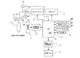
本発明について、添付図面に示した実施形態を参照して詳述する。図1は、本発明を適用した、コントラストAF方式の焦点調節装置を備えた、いわゆるコンパクトタイプのデジタルカメラの要部構成をブロックで示した図である。 The present invention will be described in detail with reference to the embodiments shown in the accompanying drawings. FIG. 1 is a block diagram showing a main configuration of a so-called compact type digital camera equipped with a contrast AF type focus adjustment apparatus to which the present invention is applied.
このデジタルカメラは、焦点調節レンズ群L1を含む撮像光学系としてのズームレンズLにより形成された被写体像を、撮像手段としての撮像素子(CCDイメージセンサ)11の受光面に投影し、露光する。撮像素子11は、所定間隔で縦横に配置された多数の画素(光電変換素子)を有し、受光した被写体像を各画素が電荷に変換して蓄積(積分)する、CCDまたはCMOSイメージセンサである。露光が終了すると、蓄積した電荷を画素単位で画像信号として画像信号処理回路13に出力する。画像信号処理回路13は、入力した画像信号についてホワイトバランス調整等所定の調整処理、A/D変換処理を施してデジタル画像データをCPU15に出力する。つまり、画像信号処理回路13において所定の処理が施され、画素単位でデジタル変換された画像データが、CPU15に出力される。CPU15は、スルーモード(モニタモード)のときは定期的に入力する画像データを、表示手段としてのモニタ(LCD)17で表示可能な画像信号に変換してモニタ17で表示し、画像を記録するときは、設定された絞り、シャッタ速度等で露光する撮像処理を実行し、入力した画像データを所定フォーマットの画像データに変換して画像メモリ制御回路19を介して画像メモリ21に書き込む記録処理を実行する。さらにCPU15には、設定された所定フォーマットや可変データなどが書き込まれた不揮発性メモリとしてEEPROM29が接続されている。
This digital camera projects and exposes a subject image formed by a zoom lens L as an imaging optical system including a focus adjustment lens group L1 onto a light receiving surface of an imaging device (CCD image sensor) 11 as imaging means. The
通常のコントラストAF処理では、第1のスイッチ手段としての測光スイッチSWSがオンされるとCPU15は、モータドライバ27、AFモータ25及びレンズ駆動機構23を介して焦点調節レンズ群L1を、一方の移動限界位置となる近位置(近端、至近合焦位置)または遠位置(遠端、無限遠合焦位置)から他方の移動限界位置となる遠位置または近位置方向にステップ移動させながら撮像素子11により撮像し、撮像した画像信号を取り込んで内部RAM15aにメモリし、フォーカスエリア内の画像のコントラストを検出する。そうして各フォーカスエリアについてコントラスト値のピークを検出し、そのピークが得られるレンズ位置、つまり合焦レンズ位置を求める焦点スキャン処理を実行し、この焦点スキャン処理により得られた合焦レンズ位置に焦点調節レンズ群L1を移動させる。さらに第2のスイッチ手段としてのレリーズスイッチSWRがオンされると、撮像処理を実行し、入力した画像データを画像メモリ21に書き込む記録処理を実行する。なお、コントラストAF処理中及び合焦後に撮像した画像信号は、通常、スルーモードによりモニタ17に表示される。
In the normal contrast AF process, when the photometric switch SWS as the first switch means is turned on, the
この実施形態では、焦点調節レンズ群L1の位置を、近位置及び遠位置を原点センサ23a、23bで検知し、各位置からのAFモータ25を駆動する駆動パルス数としてカウントする。駆動パルスは、例えばAFモータ25の出力軸に装着されたフォトインタラプタ等のエンコーダ26がAFモータ25の回転に連動して出力するパルスとして定義する。なお、通常は、焦点調節レンズ群L1を近位置から遠位置まで駆動するのに数百パルスあるいはそれ以上要するが、説明を簡単にするために本実施形態におけるコントラストAF処理では、数パルスまたは数十パルス単位でステップ駆動して焦点調節レンズ群L1が複数パルス単位で1移動単位ステップ移動するものとし、近位置から無限位置まで十数ステップで駆動できるものとする。さらに、焦点調節レンズ群L1の位置を検知する駆動パル数は、この複数パルス単位を1駆動パルスとしてカウントするものとする。
In this embodiment, the near position and the far position are detected by the
また、この実施形態では、レンズ位置パルス数をPNとし、近位置のレンズ位置パルス数PNを0として駆動パルス1個分遠位置方向に駆動する毎にレンズ位置パルス数PNを1ずつ加算するものとする。遠位置から近位置方向にスキャンする場合は、遠位置におけるレンズ位置パルス数PNをMAXとして、近位置方向に1駆動パルス駆動する毎に1ずつ減算するものとする。 Further, in this embodiment, the lens position pulse number PN is set to PN, the lens position pulse number PN at the near position is set to 0, and the lens position pulse number PN is incremented by 1 every time one drive pulse is driven in the far position direction. And When scanning from the far position to the near position direction, the lens position pulse number PN at the far position is set to MAX, and one is subtracted every time one drive pulse is driven in the near position direction.
なお、このデジタルカメラは、ズームレンズLをレンズ駆動機構23のズーム機構を介してパワーズームするズームモータ28を備え、ズームレンズLの焦点距離を検出するエンコーダをレンズ駆動機構23が内蔵している。
This digital camera includes a
このデジタルカメラは、フォーカスモードとして、スポットフォーカスモード及びマルチフォーカスモードを備えている。スポットフォーカスモードは、撮影画面中央部分に位置する1個のフォーカスフレーム内の被写体について焦点検出し、マルチフォーカスモードは撮影画面中央部分及び撮影画面内に位置する複数のフォーカスフレーム内の被写体像について焦点検出する。図2(A)、図3(A)はフォーカスモードとフォーカスフレームとの関係を示し、図2(B)、図3(B)は各フォーカスモードにおける粗いスキャン時のフォーカスエリアを示し、図2(C)、図3(C)は細かいスキャン時のフォーカスエリアを示した。 This digital camera has a spot focus mode and a multi-focus mode as focus modes. In the spot focus mode, focus detection is performed for a subject in one focus frame located at the center of the shooting screen, and in the multi-focus mode, focus is applied to subject images in a plurality of focus frames located in the center of the shooting screen and in the shooting screen. To detect. 2A and 3A show the relationship between the focus mode and the focus frame, and FIG. 2B and FIG. 3B show the focus area during rough scanning in each focus mode. (C) and FIG. 3 (C) show the focus area during fine scanning.
スポットフォーカスモードでは、中央のフォーカスフレーム18a内の被写体像についてAFスキャンを行う。フォーカスフレーム18aは、全体を一つのエリアとして焦点検出をする統合フォーカスエリア(大フォーカスエリア)αと、5個に分割して分割フォーカスエリア(小フォーカスエリア)毎に焦点検出をする分割フォーカスエリアa、b、c、d、eを含む。4個の分割フォーカスエリアb、c、d、eは統合フォーカスエリアαの4分割エリアであって、1個の分割フォーカスエリアaはフォーカスフレーム18aの中央で分割フォーカスエリアb、c、d、eの一部エリアによって構成されている。
In the spot focus mode, an AF scan is performed on the subject image in the
マルチフォーカスモードでは、フォーカスフレーム18aと、その左右に隣接したフォーカスフレーム18b、18b内の被写体像についてAFスキャンを行う。フォーカスフレーム18b、18bは、フォーカスフレーム18a同様に、全体を一つのフォーカスエリア(大フォーカスエリア)として焦点検出をする統合フォーカスエリアβ、γと、統合フォーカスエリアβ、γをそれぞれ5個に分割して分割フォーカスエリア(小フォーカスエリア)毎に焦点検出をする分割フォーカスエリアf、g、h、i、j、及び分割フォーカスエリアk、l、m、n、oを含む。各4個の分割フォーカスエリアg、h、i、j及びl、m、n、oは統合フォーカスエリアβ、γの4分割エリアであって、中央の1個の分割フォーカスエリアf及びkは4分割フォーカスエリアg、h、i、j及びl、m、n、oの一部エリアと重複している。
In the multi-focus mode, AF scanning is performed on the
さらに本発明の実施形態では、粗い、細かいフォーカススキャンなどの複数の精度によりフォーカススキャンをする機能を備えている。粗いフォーカススキャンでは、焦点調節レンズ群L1を高速移動、つまり停止させる位置パルス数[PN]の間隔を広くし、細かいフォーカススキャンでは、焦点調節レンズ群L1を低速移動、つまり停止させる位置パルス数[PN]の間隔を狭くする。粗いフォーカススキャンでは、統合フォーカスエリアα、β、γ単位で焦点検出を実行し、細かいフォーカススキャンでは分割フォーカスエリアa乃至o単位で焦点検出を実行する。 Furthermore, the embodiment of the present invention has a function of performing focus scanning with a plurality of accuracy such as coarse and fine focus scanning. In the coarse focus scan, the interval of the number of position pulses [PN] for moving the focus adjusting lens group L1 at high speed, that is, the position pulse [PN] is widened. PN] interval is narrowed. In the coarse focus scan, focus detection is executed in units of the integrated focus areas α, β, and γ, and in the fine focus scan, focus detection is executed in units of the divided focus areas a to o.
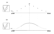
次に、このデジタルカメラ10によるフォーカススキャン処理における、焦点調節レンズ群L1の位置とコントラストとの関係について、図4(A)乃至(C)を参照して説明する。本発明の実施形態では、スポットフォーカスモードにおいて、合焦していない状態からの1回目のフォーカススキャン処理では、近位置から遠位置までの全距離について粗いフォーカススキャン処理を実行し、この粗いフォーカススキャン処理によりコントラストピークが得られた場合は、そのピークが得られたレンズ位置の前後所定範囲について細かいフォーカススキャン処理を実行する(図4(A))。ここでは、粗いフォーカススキャンの1移動ステップ幅は、細かいフォーカススキャンの1移動ステップ幅の4倍である。
Next, the relationship between the position of the focus adjustment lens group L1 and the contrast in the focus scan processing by the
ここで、スポットフォーカスフレーム18a内に、近距離の被写体51と、遠距離の被写体53が含まれていたと仮定する。すると、粗いフォーカススキャン処理では、遠近の被写体51、53を重ね合わせた状態でコントラストが検出されるので、レンズ位置によるコントラストの変化がなだらかになる。但し、それぞれの被写体51、53について単独でコントラストを検出すると、それぞれの被写体51、53についてコントラストのピークが出現する(図4(B)、(C))。しかし、これらの被写体51、53を同時に含むフォーカスエリアによりフォーカススキャンすると、図4(A)に示したように、これらの被写体51、53間をコントラストピークとするなだらかなコントラストピークが得られる。かかる場合に、このコントラストピーク位置を挟む所定範囲内において細かいコントラストピークを実行しても、被写体51、53に対してのコントラストピークは得られない。
Here, it is assumed that the short-
また、遠近の被写体が前後に重なって含まれている場合がある。この現象は、特にマクロ撮影において生じやすい。このような被写体状態を図5(A)に示した。この被写体状態では、スポットフォーカスフレーム18a内、つまり、統合フォーカスエリアα内の画像は、近位置の葉61と遠位置の葉63が交叉し、さらに近位置の葉61に昆虫65が留まった状態のものとなっている(図5(B)、(C))。
In addition, there are cases where near and far subjects are included overlapping each other. This phenomenon is particularly likely to occur in macro photography. Such a subject state is shown in FIG. In this subject state, an image in the
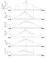
このような被写体状態において統合フォーカスエリアαを使用した粗いフォーカススキャンを行うと、葉61、63及び昆虫65の輝度を平均した輝度に基づいてピーク位置RPが検出される(図6(A))。かかる被写体の場合は、1移動ステップ幅を狭くした細かいフォーカススキャンを実行しても同様である(図6(B))。
When a rough focus scan using the integrated focus area α is performed in such a subject state, the peak position RP is detected based on the brightness obtained by averaging the brightness of the
一方、分割フォーカスエリアa乃至e内の被写体は、図5(D)に示したように、遠近の被写体が含まれる率及び同程度の面積で含まれる率が低くなり、同一距離の被写体が含まれる率が高く、単一の被写体が占める割合、面積が大きくなっている。 On the other hand, as shown in FIG. 5D, the subjects in the divided focus areas a to e are low in the rate of including near-distance subjects and in the same area, and include subjects of the same distance. The ratio and area occupied by a single subject is large.
そこで本実施形態では、粗いスキャンにより統合フォーカスエリアαを使用して急峻な1個のピークが得られなかった場合は、細かいスキャンにより分割フォーカスエリアa乃至eを使用した細フォーカススキャンを実行する。細フォーカススキャンによれば、各分割フォーカスエリアa乃至e内の主要被写体61乃至65に対するコントラストピークを検出できる(図7(B)乃至(F))。
Therefore, in the present embodiment, when one steep peak cannot be obtained using the integrated focus area α by the coarse scan, the fine focus scan using the divided focus areas a to e is executed by the fine scan. According to the fine focus scan, contrast peaks for the
細かいフォーカスサーチ処理では、焦点調節レンズ群L1を細かいステップでステップ移動させながら、分割フォーカスエリアa乃至eについてコントラストを求める。図7(B)乃至図(F)に、各分割フォーカスエリアa乃至eについての焦点調節レンズ群L1位置とコントラストとの関係を示した。 In the fine focus search process, the contrast is obtained for the divided focus areas a to e while moving the focus adjustment lens unit L1 step by step. FIGS. 7B to 7F show the relationship between the focus adjustment lens group L1 position and contrast for each of the divided focus areas a to e.
この実施形態では、スキャン範囲、スキャン駆動速度及びフォーカスエリアの組み合わせが異なるスキャンタイプ(Scan-Type)を4種類備えている。 In this embodiment, four types of scan types (Scan-Type) having different combinations of scan ranges, scan drive speeds, and focus areas are provided.
スキャン範囲は、全体と部分の二種類備えている。全体スキャンは、近位置から遠位置までの全領域をスキャン範囲とする。部分スキャンは、近位置から遠位置間の一部分をスキャン範囲とする。 There are two types of scan ranges: whole and part. In the entire scan, the entire area from the near position to the far position is set as the scan range. In the partial scan, a part between a near position and a far position is set as a scan range.
スキャン駆動速度はVA、VB、VCの三種類備えている。大小関係は、VA>VB>VC である。例えば、焦点調節レンズ群L1を、低速スキャン駆動速度VCでは1駆動パルス単位でステップ移動し、中速スキャン駆動速度VBでは2駆動パルス単位でステップ移動し、高速スキャン駆動速度VAでは4駆動パルス単位でステップ移動する。 There are three types of scan drive speeds: VA, VB, and VC. The magnitude relationship is VA> VB> VC. For example, the focus adjustment lens unit L1 is stepped in units of one drive pulse at the low-speed scan drive speed VC, is stepped in units of two drive pulses at the medium-speed scan drive speed VB, and is unit of four drive pulses at the high-speed scan drive speed VA. Step by step.
フォーカスエリアは、スポット測距では統合フォーカスエリアα及び分割フォーカスエリアa乃至e、マルチ測距では統合フォーカスエリアα乃至γ及び統合フォーカスエリアα乃至γに含まれる分割フォーカスエリアa乃至e、f乃至j、k乃至oを備えている。これらを、表1に示した。 The focus areas are integrated focus areas α and divided focus areas a to e for spot ranging, and divided focus areas a to e and f to j included in integrated focus areas α to γ and integrated focus areas α to γ for multi-range measurement. , K to o. These are shown in Table 1.
<表1>

この実施形態では、スキャンタイプ0が粗いフォーカススキャン、スキャンタイプ1、3が細かいフォーカススキャン、スキャンタイプ2が中間フォーカススキャンに相当する。
In this embodiment, scan
次に、このデジタルカメラ10における自動焦点調節処理について、図8乃至図10に示したフローチャートを参照してより詳細に説明する。
Next, the automatic focus adjustment process in the
『メイン処理』
図8は、このデジタルカメラのメインシーケンスをフローチャートで示した図である。このメインシーケンスには、バッテリ(図示せず)が装填されたときに入る。
"Main processing"
FIG. 8 is a flowchart showing the main sequence of this digital camera. This main sequence is entered when a battery (not shown) is loaded.
メインシーケンスに入ると、先ずステップS101において現在電源がONしているか否かをチェックする。現在電源がONしていない場合(S101:NO)はメインスイッチSWMがOFFからONに変化したかどうかをチェックし(S103)、変化していなければ(S103:NO)、ステップS103に戻る。つまり、メインスイッチSWMのチェック処理を繰り返す。メインスイッチSWMがONに変化していれば(S103:YES)、内部RAM、ポート、変数などハード、ソフト的な初期化を実行し(S105)、電源をオンして各部材に電源を供給する電源ON処理を実行し(S107)、ステップS109に進む。 When the main sequence is entered, it is first checked in step S101 whether the power supply is currently turned on. If the power is not currently turned on (S101: NO), it is checked whether or not the main switch SWM has changed from OFF to ON (S103). If it has not changed (S103: NO), the process returns to step S103. That is, the check process of the main switch SWM is repeated. If the main switch SWM is changed to ON (S103: YES), hardware and software initialization such as internal RAM, ports, and variables are executed (S105), the power is turned on and power is supplied to each member. A power ON process is executed (S107), and the process proceeds to step S109.
S109では、メインスイッチSWMがOFFからONに変化したかどうかをチェックし、変化していなければ(S109:NO)、測光スイッチSWSがONしているかどうかチェックする(S111)。測光スイッチSWSがONしていなければ(S111:NO)、ステップS101に戻る。電源ON状態でS101に戻るので、現在電源ONと判定し(S101:YES)、ステップS109に進む。つまり、電源ON状態の間は、メインスイッチSWMがOFFからONに変化するか、測光スイッチSWSがONするまでステップS101、S109のチェック処理を繰り返す。このチェック処理中にメインスイッチSWMがOFFからONに変化すると(S109:YES)、電源OFF処理を実行して(S121)、ステップS101、S103のメインスイッチSWMのチェック処理に戻る。 In S109, it is checked whether or not the main switch SWM has changed from OFF to ON. If it has not changed (S109: NO), it is checked whether or not the photometric switch SWS is ON (S111). If the photometric switch SWS is not turned on (S111: NO), the process returns to step S101. Since the process returns to S101 when the power is on, it is determined that the power is currently on (S101: YES), and the process proceeds to step S109. That is, while the power is on, the check processing in steps S101 and S109 is repeated until the main switch SWM changes from OFF to ON or the photometry switch SWS is turned on. If the main switch SWM changes from OFF to ON during this check process (S109: YES), the power OFF process is executed (S121), and the process returns to the main switch SWM check process in steps S101 and S103.
測光スイッチSWSがONすると(S111;YES)、コントラストAF処理を実行して焦点調節レンズ群L1を所定の被写体に対して合焦させる(S113)。次に、測光スイッチSWSがONしているかどうかチェックし(S115)、測光スイッチSWSがONしていればレリーズスイッチSWRがONしているかいなかチェックし(S115:YES、S117)、レリーズスイッチSWRがONしていなければ、(S117;NO)、ステップS115に戻って測光スイッチSWS、レリーズスイッチSWRがONしているかどうかのチェックを繰り返す(S115、S117)。 When the photometry switch SWS is turned on (S111; YES), a contrast AF process is executed to focus the focus adjustment lens group L1 on a predetermined subject (S113). Next, it is checked whether or not the metering switch SWS is ON (S115). If the metering switch SWS is ON, it is checked whether or not the release switch SWR is ON (S115: YES, S117). If it is not ON (S117; NO), the process returns to step S115 to repeat the check whether the photometry switch SWS and release switch SWR are ON (S115, S117).
レリーズスイッチSWRがONすると(S117:YES)、撮像処理を実行し(S121)、ステップS101に戻る。測光スイッチSWSがOFFすると(S115:NO)、そのままステップS101に戻る。 When the release switch SWR is turned on (S117: YES), an imaging process is executed (S121), and the process returns to step S101. When the photometry switch SWS is turned off (S115: NO), the process returns to step S101 as it is.
『コントラストAF処理』
次に、ステップS113で実行されるコントラストAF処理の詳細について、さらに図9に示したフローチャートを参照して説明する。
"Contrast AF processing"
Next, details of the contrast AF process executed in step S113 will be described with reference to the flowchart shown in FIG.
コントラストAF処理に入ると、まず各変数等の初期化を実行する(S201)。例えばこの実施形態では、各ステータスのクリア、コントラスト値のクリア、レンズ位置パルス数PNの初期化(PN=0)、コントラストの最大値、最小値の初期化(最大値=0、最小値=FFFFFFFF)、スキャンタイプ(Scan Type)の初期化(初期値は0)等を実行する。 When the contrast AF process is started, initialization of each variable and the like is first executed (S201). For example, in this embodiment, each status is cleared, the contrast value is cleared, the lens position pulse number PN is initialized (PN = 0), the contrast maximum value and the minimum value are initialized (maximum value = 0, minimum value = FFFFFFFF). ), Scan type initialization (initial value is 0), and the like.
コントラスト値は、各フォーカスエリア、サポートエリア内の画素から得られた実際に得られたコントラスト値である。
レンズ位置パルス数PNは、焦点調節レンズ群L1が初期位置である近位置にあるときを0として、∞位置方向にAFモータ25を駆動したときにエンコーダ26から駆動パルスが1個出力される毎にカウントする変数である。スキャン駆動速度VAのときは、駆動パルスが4個単位で出力され、レンズ位置パルス数PNが4個分カウントされる。スキャンタイプVBのときは駆動パルスが2個単位で出力され、レンズ位置パルス数PNが2個分カウントされる。スキャンタイプVCのときは駆動パルスが1個単位で出力され、レンズ位置パルス数PNが1個分カウントされる。
コントラストの最大値、最小値は、実際に得られたコントラスト値の最大値、最小値である。
スキャンタイプ(Scan-Type)は、表1に示したように、スキャン範囲、スキャン駆動速度、及び対象エリアを設定する変数である。
The contrast value is an actually obtained contrast value obtained from the pixels in each focus area and support area.
The lens position pulse number PN is set to 0 when the focusing lens group L1 is in the near position, which is the initial position, and every time one drive pulse is output from the
The maximum and minimum values of contrast are the maximum and minimum values of the contrast value actually obtained.
As shown in Table 1, the scan type (Scan-Type) is a variable that sets a scan range, a scan drive speed, and a target area.
次に、フォーカスイニシャライズ処理を実行する(S203)。フォーカスイニシャライズ処理は、焦点調節レンズ群L1をスキャン開始位置に移動させる処理である。コントラストAF処理に入って1回目では、焦点調節レンズ群L1を近位置に移動させる。 Next, focus initialization processing is executed (S203). The focus initialization process is a process of moving the focus adjustment lens group L1 to the scan start position. In the first time after entering the contrast AF process, the focus adjustment lens unit L1 is moved to the near position.
続いて、スキャン駆動速度を設定し(S205)、フォーカスエリアを設定する(S207)。1回目は、スキャンタイプ0が設定されているので、高速スキャン駆動速度VAを設定する。フォーカスエリアは、スポット測距の場合は中領域αを、マルチ測距の場合は中領域α、β、γを設定する。
Subsequently, the scan drive speed is set (S205), and the focus area is set (S207). Since the
次に、スキャン初期位置(1回目は近位置)における画像データを取得してコントラスト値算出処理を実行する(S209)。つまり、撮像素子11から入力した画像データに基づいて、初期位置におけるコントラスト値P[0]を算出し、コントラスト値の最大値、最小値を更新する。
Next, the image data at the initial scan position (the first position is the near position) is acquired, and the contrast value calculation process is executed (S209). That is, the contrast value P [0] at the initial position is calculated based on the image data input from the
AFモータ25をスキャン終了端方向にレンズ駆動速度に対応するパル数分駆動する(S211)。そうして、撮像素子11から画像データを入力してコントラスト値P[PN]を算出し、コントラスト値の最大値、最小値を更新するコントラスト値算出処理を実行し(S213)、エンコーダ26から出力されたパルス数分、レンズ位置パルス数PNをインクリメントする(S215)。
The
次に、得られたコントラスト値P[PN]が設定条件を満足するピーク値(極大値)であるかどうかをチェックするピークチェック処理を実行する(S217)。コントラスト値算出処理(S213)及びピークチェック処理(S215)は、ステップS207で設定された全てのフォーカスエリアについて実行する。 Next, peak check processing for checking whether or not the obtained contrast value P [PN] is a peak value (maximum value) that satisfies the setting condition is executed (S217). The contrast value calculation process (S213) and the peak check process (S215) are executed for all the focus areas set in step S207.
スキャン終了端であるか否かをチェックする(S219)。スキャン終了端でない場合(S219;NO)はステップS211に戻ってステップS211乃至S217、S219の処理を、焦点調節レンズ群L1をスキャン終了端方向に、設定されたスキャン駆動速度(ステップ移動幅)でステップ移動させながらスキャンループを繰り返す。 It is checked whether or not it is the end of scanning (S219). If it is not the scan end end (S219; NO), the process returns to step S211, and the processing of steps S211 to S217 and S219 is performed with the focus adjustment lens group L1 in the scan end end direction at the set scan drive speed (step movement width). Repeat the scan loop while stepping.
焦点調節レンズ群L1がスキャン終了端に達すると(S219;YES)、このスキャンループを抜ける。以上のスキャンタイプ0によるフォーカススキャンが第1スキャン段階である。
When the focus adjustment lens unit L1 reaches the end of scanning (S219; YES), the scanning loop is exited. The focus scan based on the
スキャンループを抜けると(S219;YES)、スキャンタイプ及びコントラストピークが存在した否か(合焦位置が検出できたか否か)のチェック処理を行う(S221、S225、S227、S231、S235)。先ず、スキャンタイプ0でコントラストのピークが存在したか否かチェックする(S221)。スキャンタイプ0でピークが存在した場合(S221:YES)は、スキャンタイプを1に書き換えてステップS203に戻る(S223、S203)。つまり、粗いフォーカススキャンでコントラストのピークが得られた場合は、分割エリアを使用してより細かいフォーカススキャンをするためにスキャンタイプを1に書き換えてステップS203に戻る。フォーカスイニシャライズ処理に戻ると、ピーク位置RPからnパルス加算したレンズ位置(焦点スキャン開始位置)に焦点調節レンズ群L1を移動させ、ピーク位置RPにnパルス加算したレンズ位置を焦点スキャン終了位置に設定する。そうして、ピーク位置RP-n乃至RP+n部分を、低スキャン駆動速度VCで駆動させながら分割フォーカスエリアa乃至e内の画像データに基づいてコントラストピークをスキャンする。このフォーカススキャンが、第2スキャン段階である。 After exiting the scan loop (S219; YES), a check process is performed to check whether or not a scan type and a contrast peak exist (whether the in-focus position has been detected) (S221, S225, S227, S231, and S235). First, it is checked whether or not there is a contrast peak in the scan type 0 (S221). If there is a peak in scan type 0 (S221: YES), the scan type is rewritten to 1 and the process returns to step S203 (S223, S203). That is, when a contrast peak is obtained by a coarse focus scan, the scan type is rewritten to 1 in order to perform a finer focus scan using the divided areas, and the process returns to step S203. Returning to the focus initialization process, the focus adjustment lens group L1 is moved from the peak position RP to the lens position (focus scan start position) obtained by adding n pulses, and the lens position obtained by adding n pulses to the peak position RP is set as the focus scan end position. To do. Then, contrast peaks are scanned based on the image data in the divided focus areas a to e while driving the peak positions RP-n to RP + n at the low scan driving speed VC. This focus scan is the second scan stage.
スキャンタイプ0でない場合、またはスキャンタイプ0であってもコントラストピーク(合焦位置)が検出できなかった場合(S221;NO)は、スキャンタイプが1か否かチェックする(S225)。スキャンタイプが1であった場合(S225;YES)は、スキャンタイプ1によるフォーカススキャンで得た各分割フォーカスエリアa乃至e内の画像データに基づいて得たコントラスト値に基づいてピーク算出処理を実行し(S239)、エリア選択処理を実行して(S241)、選択したエリアについて算出したピーク位置(合焦レンズ位置)まで焦点調節レンズ群L1を移動させる合焦駆動処理を実行し(S243)、リターンする(RETURN)。エリア選択処理では、例えば最近距離に相当するピーク位置を選択する。
If the scan type is not 0, or if the contrast peak (in-focus position) cannot be detected even if the scan type is 0 (S221; NO), it is checked whether the scan type is 1 (S225). When the scan type is 1 (S225; YES), the peak calculation process is executed based on the contrast value obtained based on the image data in each of the divided focus areas a to e obtained by the focus scan by the
スキャンタイプ1でなかった場合(S225;NO)は、スキャンタイプ0であるかどうかをチェックする(S227)。スキャンタイプ0の場合(S227;YES)は、スキャンタイプを2に書き換えて(S229)、ステップS203に戻る。フォーカスイニシャライズ処理(S203)では、焦点調節レンズ群L1を近位置に移動させて、スキャン終了位置を遠位置に設定する。ステップS227においてスキャンタイプ0と判定される場合は、スキャンタイプ0でフォーカススキャンしたがコントラストのピークを検出できなくて来た場合である。つまり、スキャンタイプ0の粗いフォーカススキャン処理を実行してもコントラストピークの検出ができなかった場合は、スキャンタイプ2により、全体を中スキャン駆動速度VBで駆動させながら統括フォーカスエリアα乃至γ内の画像データに基づいてコントラストピークをスキャンする。このフォーカススキャン処理が第3スキャン段階である。
If the scan type is not 1 (S225; NO), it is checked whether the scan type is 0 (S227). If the scan type is 0 (S227; YES), the scan type is rewritten to 2 (S229), and the process returns to step S203. In the focus initialization process (S203), the focus adjustment lens unit L1 is moved to the near position, and the scan end position is set to the far position. If it is determined in step S227 that the scan type is 0, the focus scan is performed using the
スキャンタイプ0でなかった場合(S227:NO)は、スキャンタイプ2かつピークが存在したか否かをチェックする(S231)。スキャンタイプ2かつピークが存在した場合(S231;YES)は、スキャンタイプを1に書き換えて(S233)、ステップS203に戻る。ステップS203のフォーカスイニシャライズ処理では、検出したピーク位置RPからnパルス減算したレンズ位置パルス数[PR-n](フォーカススキャン開始位置)に焦点調節レンズ群L1を移動させ、ピーク位置RPにnパルス加算したレンズ位置パルス数[PR+n]を焦点スキャン終了位置に設定する。つまり、フォーカススキャン範囲をピーク位置PRの±n範囲に限定し、低速レンズ駆動速度VCにより、分割フォーカスエリアa乃至e毎にコントラストピークをスキャンする。このフォーカススキャン処理が、第4スキャン段階である。
When the scan type is not 0 (S227: NO), it is checked whether the
スキャンタイプ2でなかった場合、またはスキャンタイプ2でもコントラストピークが存在しなかった場合(S231;NO)は、スキャンタイプが2か否かチェックする(S235)。スキャンタイプ2であった場合(S235;YES)は、スキャンタイプを3に書き換えて(S237)、ステップS203に戻る。フォーカスイニシャライズ処理では、焦点調節レンズ群L1を近位置に移動させて、焦点スキャン終了端を遠位置に設定する。ステップS239で、スキャンタイプ2と判定される場合は、ステップS229で設定されたスキャンタイプ2でフォーカススキャンしてもピーク検出ができなかった場合である。そこで、スキャンタイプ3により、最も遅い低速レンズ駆動速度VCで、全範囲について、分割フォーカスエリアa乃至eについてコントラストピークをスキャンするのである。このフォーカススキャン処理が、第5スキャン段階に相当する。
If the scan type is not 2, or if there is no contrast peak in the scan type 2 (S231; NO), it is checked whether the scan type is 2 (S235). If the scan type is 2 (S235; YES), the scan type is rewritten to 3 (S237), and the process returns to step S203. In the focus initialization process, the focus adjustment lens unit L1 is moved to the near position, and the end point of the focus scan is set to the far position. If it is determined in step S239 that the scan type is 2, the peak cannot be detected even if the focus scan is performed using the
スキャンタイプが2でなかった場合(S235;NO)は、ピーク算出処理を実行し(S239)、エリア選択処理を実行して(S241)、選択したエリアについて算出したピーク位置(合焦レンズ位置)まで焦点調節レンズ群L1を移動させる合焦駆動処理を実行し(S243)、リターンする(RETURN)。ステップS235でスキャンタイプが2ではないと判定されるのは、S237スキャンタイプが3に書き換えられた場合である。 When the scan type is not 2 (S235; NO), the peak calculation process is executed (S239), the area selection process is executed (S241), and the peak position (focusing lens position) calculated for the selected area is executed. The focus drive process for moving the focus adjustment lens unit L1 is executed (S243), and the process returns (RETURN). It is determined in step S235 that the scan type is not 2 when the S237 scan type is rewritten to 3.
『フォーカスイニシャライズ処理』
次に、ステップS203で実行されるフォーカスイニシャライズ処理について、図10を参照して説明する。フォーカスイニシャライズ処理に入ると、先ず、スキャンタイプが0、2及び3のいずれかであるかどうかをチェックする(S301)。これらのスキャンタイプ0、2、3は、スキャン範囲が近位置から遠位置までの全範囲である。スキャンタイプが0、2及び3のいずれかであった場合(S301;YES)は、焦点調節レンズ群L1を近位置に向かって駆動を開始し(S303)、スキャン終了位置を遠位置に設定する(S305)。そうして、焦点調節レンズ群L1が近位置に達してAFモータ25が停止したか否かチェックし(S311)、停止したらリターンする(S311;YES、RETURN)。
"Focus initialization process"
Next, the focus initialization process executed in step S203 will be described with reference to FIG. In the focus initialization process, first, it is checked whether the scan type is any of 0, 2, and 3 (S301). In these
スキャンタイプが0、2及び3のいずれでも無かった場合(S301;NO)、つまりスキャンタイプが1であった場合は、焦点調節レンズ群L1を、ピーク位置RPから所定ステップ数n減算したパルス数(RP - n)のレンズ位置パルスPNに向かって駆動を開始し(S307)、スキャン終了位置として、ピーク位置RPに所定ステップ数n加算したパルス数(RP + n)をレンズ位置パルスPNにセットする(S309)。そうして、焦点調節レンズ群L1がレンズ位置[RP - n]に達してAFモータ25が停止したかどうかチェックし(S311)、停止したらリターンする(S311;YES、RETURN)。
なお、この実施形態におけるAFモータ25の駆動制御は、フォーカスイニシャライズ処理とは別個のモータ制御スレッドによって実行される。
When the scan type is neither 0, 2, or 3 (S301; NO), that is, when the scan type is 1, the number of pulses obtained by subtracting the focus adjustment lens group L1 by the predetermined number of steps n from the peak position RP. The driving is started toward the lens position pulse PN of (RP−n) (S307), and the number of pulses (RP + n) obtained by adding a predetermined number of steps n to the peak position RP is set in the lens position pulse PN as the scan end position. (S309). Then, it is checked whether the focus adjustment lens group L1 has reached the lens position [RP-n] and the
Note that the drive control of the
『スキャン駆動速度設定』
ステップS205で実行されるスキャン駆動速度設定処理について、図11に示したフローチャートを参照して説明する。スキャン駆動速度設定処理に入ると、先ず、スキャンタイプ0かどうかチェックする(S401)。スキャンタイプ0の場合は(S401:YES)、スキャン駆動速度をVAに設定してリターンする(S403、RETURN)。
“Scan drive speed setting”
The scan drive speed setting process executed in step S205 will be described with reference to the flowchart shown in FIG. When the scan drive speed setting process is entered, first, it is checked whether or not the scan type is 0 (S401). If the scan type is 0 (S401: YES), the scan drive speed is set to VA and the process returns (S403, RETURN).
スキャンタイプ0で無い場合は(S405:NO)、スキャンタイプ2かどうかチェックし(S405)、スキャンタイプ2である場合は(S405:YES)スキャン駆動速度をVBに設定してリターンする(S407、RETURN)。スキャンタイプ2でない場合(S405:NO)、つまりスキャンタイプ1または3の場合は(S405:NO)、スキャン駆動速度をVCに設定してリターンする(S409、RETURN)。 If the scan type is not 0 (S405: NO), it is checked whether the scan type is 2 (S405). If the scan type is 2 (S405: YES), the scan drive speed is set to VB and the process returns (S407, S405). RETURN). When the scan type is not 2 (S405: NO), that is, when the scan type is 1 or 3 (S405: NO), the scan drive speed is set to VC and the process returns (S409, RETURN).
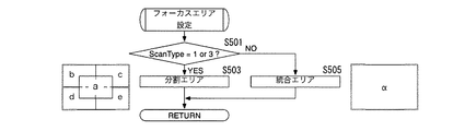
『フォーカスエリア設定』
ステップS207で実行されるフォーカスエリア設定処理について、図12に示したフローチャートを参照して説明する。フォーカスエリア設定処理に入ると、先ずスキャンタイプが1または3であるかどうかをチェックする(S501)。スキャンタイプ1または3であった場合(S501;YES)は、フォーカスエリアとして分割エリアを選択してリターンする(S503、RETURN)。スキャンタイプ1、3のいずれでも無い場合(S501;NO)、つまりスキャンタイプ0または2であった場合は、フォーカスエリアとして統合エリアを選択してリターンする(S505、RETURN)。
"Focus area setting"
The focus area setting process executed in step S207 will be described with reference to the flowchart shown in FIG. In the focus area setting process, first, it is checked whether the scan type is 1 or 3 (S501). If the scan type is 1 or 3 (S501; YES), a divided area is selected as the focus area and the process returns (S503, RETURN). If none of the
フォーカスモードとしてマルチフォーカスモードが選択されている場合は、前記第1スキャン段階においては各統合(大)フォーカスエリアα乃至γについてコントラストピーク(合焦位置)を検出し、最短距離に相当するコントラストピークが得られた1個の統合フォーカスエリアα乃至γ及びその分割(小)フォーカスリアa乃至oについて、スキャンタイプ1乃至3によるフォーカススキャン(第2乃至第5スキャン段階)を実行することが好ましい。
When the multi-focus mode is selected as the focus mode, a contrast peak (focus position) is detected for each integrated (large) focus area α to γ in the first scanning stage, and the contrast peak corresponding to the shortest distance is detected. It is preferable to execute focus scans (second to fifth scan stages) by
別の実施例では、前記スキャンタイプ0によるフォーカススキャンにおいて検出した合焦位置が所定距離より近距離の場合に前記スキャンタイプ1乃至3(第2乃至第5スキャン段階)を実行する構成とする。この場合、前記スキャンタイプ0により検出した合焦位置が所定距離より近距離ではない場合は、前記検出した合焦位置に前記焦点調節レンズ群を移動させる構成としてもよい。
In another embodiment, the
このデジタルカメラ10は、マクロモードまたはスーパーマクロモードとこれら以外の撮影モードを選択する撮影モード選択手段を含み、撮影モード選択手段により前記マクロモードまたはスーパーマクロモードが選択されていた場合に前記第1スキャン段階及びそれ以降の段階を実行し、これらのいずれかのマクロモードが選択されていない場合は、前記焦点調節レンズ群L1を、前記可動範囲全体に渡って、好ましくはレンズ駆動速度VCでステップ移動させながら、前記統合フォーカスエリアα乃至γ内の画像に基づいてフォーカススキャンし、そのスキャンで得られた合焦位置に前記焦点調節レンズ群L1を移動させるように構成する。
The
11 撮像素子(撮像手段)
12 受光面
13 画像信号処理回路
15 CPU(制御手段)
15a 内部RAM
17 モニタ(LCD)
18 画面
18a 18b 18c フォーカスエリア
19 メモリ制御回路
21 画像メモリ
23 モータドライバ
23a 近端原点センサ
23b 遠端原点センサ
25 AFモータ(レンズ駆動手段)
26 エンコーダ
27 レンズ駆動機構
28 ズームモータ
29 EEPROM(不揮発性メモリ)
L ズームレンズ(撮像光学系)
L1 焦点調節レンズ群
11 Imaging device (imaging means)
12
15a Internal RAM
17 Monitor (LCD)
18
26
L Zoom lens (imaging optical system)
L1 Focusing lens group
Claims (14)
前記焦点調節レンズ群を、前記可動範囲全体に渡ってステップ移動させながら、前記大フォーカスエリア内の画像に基づいてフォーカススキャンする第1スキャン段階と、
前記焦点調節レンズ群を、前記第1スキャン段階において検出された合焦位置の前後部分においてステップ移動させながら、前記小フォーカスエリア内の画像に基づいてフォーカススキャンする第2スキャン段階と、を含むことを特徴とする焦点調節方法。 At least one large focus area or smaller than the large focus area formed by the photographing optical system while step-moving the focusing lens group of the photographing optical system from the closest end or the infinity end toward the other end. A focus adjustment method for executing a focus scan for obtaining a focus state based on the contrast of each image in a plurality of small focus areas included in the large focus area and moving the focus adjustment lens group to a detected focus position. ,
A first scanning step of performing a focus scan based on an image in the large focus area while step-moving the focus adjustment lens group over the entire movable range;
A second scanning step of performing a focus scanning based on an image in the small focus area while moving the focus adjustment lens group stepwise in front and rear portions of the in-focus position detected in the first scanning step. Focus adjustment method characterized by.
前記撮影光学系によって形成された画像を撮像する撮像手段と、
前記レンズ駆動手段を介して前記焦点調節レンズ群をステップ移動させながら前記撮像手段により撮像し、該撮像手段が撮像した、少なくとも1個の大フォーカスエリアまたは該大フォーカスエリアに含まれる複数の小フォーカスエリアにおける各画像に基づいて焦点状態を求めるフォーカススキャンのいずれかを実行する制御手段とを備えたこと、を特徴とする焦点調節装置。 A lens driving means for step-moving the focusing lens group of the photographing optical system in the near end direction or the infinity end direction within a movable range to the near end or the infinity end;
Imaging means for imaging an image formed by the imaging optical system;
At least one large focus area or a plurality of small focus areas included in the large focus area captured by the imaging unit while stepping the focus adjustment lens group via the lens driving unit and captured by the imaging unit And a control means for executing any one of focus scans for obtaining a focus state based on each image in the area.
Priority Applications (2)
| Application Number | Priority Date | Filing Date | Title |
|---|---|---|---|
| JP2007191729A JP4951433B2 (en) | 2007-07-24 | 2007-07-24 | Focus adjustment method and focus adjustment apparatus |
| US12/177,421 US7831138B2 (en) | 2007-07-24 | 2008-07-22 | Focus adjusting method and focus adjusting device |
Applications Claiming Priority (1)
| Application Number | Priority Date | Filing Date | Title |
|---|---|---|---|
| JP2007191729A JP4951433B2 (en) | 2007-07-24 | 2007-07-24 | Focus adjustment method and focus adjustment apparatus |
Publications (2)
| Publication Number | Publication Date |
|---|---|
| JP2009025770A true JP2009025770A (en) | 2009-02-05 |
| JP4951433B2 JP4951433B2 (en) | 2012-06-13 |
Family
ID=40295445
Family Applications (1)
| Application Number | Title | Priority Date | Filing Date |
|---|---|---|---|
| JP2007191729A Expired - Fee Related JP4951433B2 (en) | 2007-07-24 | 2007-07-24 | Focus adjustment method and focus adjustment apparatus |
Country Status (2)
| Country | Link |
|---|---|
| US (1) | US7831138B2 (en) |
| JP (1) | JP4951433B2 (en) |
Cited By (7)
| Publication number | Priority date | Publication date | Assignee | Title |
|---|---|---|---|---|
| WO2011068234A1 (en) * | 2009-12-02 | 2011-06-09 | Ricoh Company, Ltd. | Imaging device and imaging method |
| KR101055437B1 (en) | 2009-04-17 | 2011-08-08 | 삼성전기주식회사 | Auto focusing method |
| JP2012093409A (en) * | 2010-10-25 | 2012-05-17 | Ricoh Co Ltd | Image-pickup device and image-pickup method |
| JP2013011839A (en) * | 2011-05-31 | 2013-01-17 | Nikon Corp | Focus detection device and imaging apparatus having the same |
| JP2014123069A (en) * | 2012-12-21 | 2014-07-03 | Canon Inc | Image capturing device and control method therefor |
| KR101624654B1 (en) | 2010-03-15 | 2016-05-26 | 삼성전자주식회사 | Focusing apparatus and Focusing method |
| JP2016167839A (en) * | 2016-04-18 | 2016-09-15 | オリンパス株式会社 | Imaging apparatus and imaging method |
Families Citing this family (20)
| Publication number | Priority date | Publication date | Assignee | Title |
|---|---|---|---|---|
| WO2009028139A1 (en) * | 2007-08-29 | 2009-03-05 | Panasonic Corporation | Image picking-up device |
| JP2010054730A (en) * | 2008-08-27 | 2010-03-11 | Samsung Digital Imaging Co Ltd | Focusing position detecting device, imaging apparatus, and focusing position detecting method |
| WO2010050200A1 (en) * | 2008-10-30 | 2010-05-06 | パナソニック株式会社 | Camera system |
| JP5202270B2 (en) * | 2008-12-12 | 2013-06-05 | キヤノン株式会社 | Imaging device |
| JP2010271600A (en) * | 2009-05-22 | 2010-12-02 | Sanyo Electric Co Ltd | Electronic camera |
| US8743269B2 (en) | 2009-06-15 | 2014-06-03 | Olympus Imaging Corp. | Photographing device, photographing method, and playback method |
| JP2011150179A (en) * | 2010-01-22 | 2011-08-04 | Canon Inc | Automatic focusing apparatus |
| CN102253569B (en) * | 2011-01-17 | 2012-11-14 | 深圳市保千里电子有限公司 | Method and device for focusing camera |
| CN102934003B (en) * | 2011-04-15 | 2016-06-08 | 松下电器产业株式会社 | Imaging device, semiconductor integrated circuit, and imaging method |
| US10001622B2 (en) * | 2011-10-25 | 2018-06-19 | Sanford Burnham Medical Research Institute | Multifunction autofocus system and method for automated microscopy |
| TWI440951B (en) * | 2011-11-09 | 2014-06-11 | Altek Corp | Lens actuating device and lens actuating method thereof |
| CN103105660A (en) * | 2011-11-09 | 2013-05-15 | 华晶科技股份有限公司 | Lens actuating device and lens actuating method thereof |
| JP5934940B2 (en) * | 2012-05-17 | 2016-06-15 | パナソニックIpマネジメント株式会社 | Imaging apparatus, semiconductor integrated circuit, and imaging method |
| JP6218377B2 (en) * | 2012-12-27 | 2017-10-25 | キヤノン株式会社 | Image processing apparatus and image processing method |
| US9197809B2 (en) * | 2013-05-01 | 2015-11-24 | Canon Kabushiki Kaisha | Image pickup apparatus, method of controlling image pickup apparatus, and non-transitory computer-readable storage medium |
| US9462179B2 (en) * | 2013-05-20 | 2016-10-04 | Omnivision Technologies, Inc. | Image sensor with fast intra-frame focus |
| US9124823B2 (en) * | 2013-05-20 | 2015-09-01 | Omnivision Technologies, Inc. | Image sensor with fast intra-frame focus |
| JP2016133595A (en) * | 2015-01-19 | 2016-07-25 | キヤノン株式会社 | Controller, imaging device, control method, program, and storage medium |
| JP6415408B2 (en) * | 2015-08-28 | 2018-10-31 | キヤノン株式会社 | Output device, lens device and system |
| CN114007016A (en) * | 2021-10-29 | 2022-02-01 | 江西盛泰精密光学有限公司 | A system and method for fast automatic focusing of camera module |
Citations (3)
| Publication number | Priority date | Publication date | Assignee | Title |
|---|---|---|---|---|
| JP2001066494A (en) * | 1999-08-27 | 2001-03-16 | Ricoh Co Ltd | Auto focus device |
| JP2002311325A (en) * | 2001-04-11 | 2002-10-23 | Fuji Photo Film Co Ltd | Automatic focusing device and method |
| JP2004309586A (en) * | 2003-04-02 | 2004-11-04 | Minolta Co Ltd | Imaging device |
Family Cites Families (9)
| Publication number | Priority date | Publication date | Assignee | Title |
|---|---|---|---|---|
| JP2708904B2 (en) | 1989-08-08 | 1998-02-04 | 三洋電機株式会社 | Auto focus camera |
| US5249058A (en) | 1989-08-08 | 1993-09-28 | Sanyo Electric Co., Ltd. | Apparatus for automatically focusing a camera lens |
| US8436932B2 (en) * | 2005-04-22 | 2013-05-07 | Hewlett-Packard Development Company, L.P. | Focus target discrimination using multiple focus zones |
| JP2007251343A (en) | 2006-03-14 | 2007-09-27 | Pentax Corp | Image sensor driving device and autofocus unit |
| JP4764774B2 (en) | 2006-05-31 | 2011-09-07 | Hoya株式会社 | Camera with focus adjustment device |
| JP2007322978A (en) | 2006-06-05 | 2007-12-13 | Pentax Corp | Focus detection method and focus detection apparatus |
| US7773874B2 (en) | 2006-06-05 | 2010-08-10 | Hoya Corporation | Focus detection method and focus detection device |
| US20080136958A1 (en) | 2006-12-11 | 2008-06-12 | Pentax Corporation | Camera having a focus adjusting system and a face recognition function |
| JP4810416B2 (en) | 2006-12-19 | 2011-11-09 | Hoya株式会社 | Camera with focus adjustment device |
-
2007
- 2007-07-24 JP JP2007191729A patent/JP4951433B2/en not_active Expired - Fee Related
-
2008
- 2008-07-22 US US12/177,421 patent/US7831138B2/en not_active Expired - Fee Related
Patent Citations (3)
| Publication number | Priority date | Publication date | Assignee | Title |
|---|---|---|---|---|
| JP2001066494A (en) * | 1999-08-27 | 2001-03-16 | Ricoh Co Ltd | Auto focus device |
| JP2002311325A (en) * | 2001-04-11 | 2002-10-23 | Fuji Photo Film Co Ltd | Automatic focusing device and method |
| JP2004309586A (en) * | 2003-04-02 | 2004-11-04 | Minolta Co Ltd | Imaging device |
Cited By (10)
| Publication number | Priority date | Publication date | Assignee | Title |
|---|---|---|---|---|
| KR101055437B1 (en) | 2009-04-17 | 2011-08-08 | 삼성전기주식회사 | Auto focusing method |
| WO2011068234A1 (en) * | 2009-12-02 | 2011-06-09 | Ricoh Company, Ltd. | Imaging device and imaging method |
| JP2011138103A (en) * | 2009-12-02 | 2011-07-14 | Ricoh Co Ltd | Imaging apparatus and method |
| KR101462323B1 (en) * | 2009-12-02 | 2014-11-14 | 가부시키가이샤 리코 | Imaging device and imaging method |
| US9201211B2 (en) | 2009-12-02 | 2015-12-01 | Ricoh Company, Ltd. | Imaging device and imaging method for autofocusing |
| KR101624654B1 (en) | 2010-03-15 | 2016-05-26 | 삼성전자주식회사 | Focusing apparatus and Focusing method |
| JP2012093409A (en) * | 2010-10-25 | 2012-05-17 | Ricoh Co Ltd | Image-pickup device and image-pickup method |
| JP2013011839A (en) * | 2011-05-31 | 2013-01-17 | Nikon Corp | Focus detection device and imaging apparatus having the same |
| JP2014123069A (en) * | 2012-12-21 | 2014-07-03 | Canon Inc | Image capturing device and control method therefor |
| JP2016167839A (en) * | 2016-04-18 | 2016-09-15 | オリンパス株式会社 | Imaging apparatus and imaging method |
Also Published As
| Publication number | Publication date |
|---|---|
| US7831138B2 (en) | 2010-11-09 |
| JP4951433B2 (en) | 2012-06-13 |
| US20090028539A1 (en) | 2009-01-29 |
Similar Documents
| Publication | Publication Date | Title |
|---|---|---|
| JP4951433B2 (en) | Focus adjustment method and focus adjustment apparatus | |
| US8134635B2 (en) | Manual focus adjustment assistance apparatus | |
| EP1843185B1 (en) | Objective lens with improved focusing operation | |
| JP4576295B2 (en) | Digital camera | |
| JP4804210B2 (en) | Imaging apparatus and control method thereof | |
| JP2001141982A (en) | Automatic focusing device for electronic camera | |
| EP3079350A1 (en) | Imaging apparatus and method of controlling the same | |
| JP5450965B2 (en) | Imaging device | |
| JP6271911B2 (en) | Imaging apparatus, control method therefor, and defocus amount calculation method | |
| US7970270B2 (en) | Auto focusing apparatus and image pick-up apparatus having sub-mirror | |
| US6477327B1 (en) | Camera having image pick-up device | |
| JP4751651B2 (en) | Focus detection method and focus detection apparatus | |
| JP2001141984A (en) | Automatic focusing device for electronic camera | |
| JP2010107862A (en) | Af-bracket photographic method and device | |
| JP2010224290A (en) | camera | |
| JP2009139728A (en) | Control device | |
| JPH09297335A (en) | Automatic focusing device for camera | |
| JP2005017699A (en) | Camera | |
| JP3610218B2 (en) | Automatic focusing device, imaging device, and automatic focusing method | |
| JP6005955B2 (en) | Photometric device and imaging device | |
| JP2001141986A (en) | Electronic camera and automatic focusing device for electronic camera | |
| JP2008040084A (en) | Optical device | |
| JP4282404B2 (en) | camera | |
| JP2001141985A (en) | Electronic camera | |
| JP2009222755A (en) | Camera including automatic focusing device |
Legal Events
| Date | Code | Title | Description |
|---|---|---|---|
| A711 | Notification of change in applicant |
Free format text: JAPANESE INTERMEDIATE CODE: A712 Effective date: 20080502 |
|
| A621 | Written request for application examination |
Free format text: JAPANESE INTERMEDIATE CODE: A621 Effective date: 20100416 |
|
| A977 | Report on retrieval |
Free format text: JAPANESE INTERMEDIATE CODE: A971007 Effective date: 20110907 |
|
| A131 | Notification of reasons for refusal |
Free format text: JAPANESE INTERMEDIATE CODE: A131 Effective date: 20110927 |
|
| A521 | Request for written amendment filed |
Free format text: JAPANESE INTERMEDIATE CODE: A523 Effective date: 20111117 |
|
| A711 | Notification of change in applicant |
Free format text: JAPANESE INTERMEDIATE CODE: A712 Effective date: 20111208 |
|
| TRDD | Decision of grant or rejection written | ||
| A01 | Written decision to grant a patent or to grant a registration (utility model) |
Free format text: JAPANESE INTERMEDIATE CODE: A01 Effective date: 20120228 |
|
| A01 | Written decision to grant a patent or to grant a registration (utility model) |
Free format text: JAPANESE INTERMEDIATE CODE: A01 |
|
| A61 | First payment of annual fees (during grant procedure) |
Free format text: JAPANESE INTERMEDIATE CODE: A61 Effective date: 20120312 |
|
| FPAY | Renewal fee payment (event date is renewal date of database) |
Free format text: PAYMENT UNTIL: 20150316 Year of fee payment: 3 |
|
| R150 | Certificate of patent or registration of utility model |
Free format text: JAPANESE INTERMEDIATE CODE: R150 |
|
| S533 | Written request for registration of change of name |
Free format text: JAPANESE INTERMEDIATE CODE: R313533 |
|
| R350 | Written notification of registration of transfer |
Free format text: JAPANESE INTERMEDIATE CODE: R350 |
|
| LAPS | Cancellation because of no payment of annual fees |