JP2008242226A - Imaging apparatus and focusing control method for imaging lens - Google Patents
Imaging apparatus and focusing control method for imaging lens Download PDFInfo
- Publication number
- JP2008242226A JP2008242226A JP2007084693A JP2007084693A JP2008242226A JP 2008242226 A JP2008242226 A JP 2008242226A JP 2007084693 A JP2007084693 A JP 2007084693A JP 2007084693 A JP2007084693 A JP 2007084693A JP 2008242226 A JP2008242226 A JP 2008242226A
- Authority
- JP
- Japan
- Prior art keywords
- focus
- lens
- subject
- operation member
- response
- Prior art date
- Legal status (The legal status is an assumption and is not a legal conclusion. Google has not performed a legal analysis and makes no representation as to the accuracy of the status listed.)
- Abandoned
Links
Images










Classifications
-
- G—PHYSICS
- G03—PHOTOGRAPHY; CINEMATOGRAPHY; ANALOGOUS TECHNIQUES USING WAVES OTHER THAN OPTICAL WAVES; ELECTROGRAPHY; HOLOGRAPHY
- G03B—APPARATUS OR ARRANGEMENTS FOR TAKING PHOTOGRAPHS OR FOR PROJECTING OR VIEWING THEM; APPARATUS OR ARRANGEMENTS EMPLOYING ANALOGOUS TECHNIQUES USING WAVES OTHER THAN OPTICAL WAVES; ACCESSORIES THEREFOR
- G03B13/00—Viewfinders; Focusing aids for cameras; Means for focusing for cameras; Autofocus systems for cameras
- G03B13/32—Means for focusing
Landscapes
- Physics & Mathematics (AREA)
- General Physics & Mathematics (AREA)
- Focusing (AREA)
- Automatic Focus Adjustment (AREA)
- Studio Devices (AREA)
Abstract
【課題】合焦位置を効率的に検出して合焦時間を短くする。
【解決手段】レリーズボタンが半押しとされると、その時点でのフォーカスレンズ15aのレンズ位置が調べられる。このフォーカスレンズ15aのレンズ位置が無限遠レンズ位置と最短レンズ位置との中間の中間レンズ位置よりも近距離側にある場合には、フォーカスレンズ15aを近距離側レンズ端より遠距離レンズ端に向けて移動させ、中間レンズ位置よりも遠距離側にある場合には、フォーカスレンズ15aを遠距離側レンズ端より近距離レンズ端に向けて移動させて、合焦位置を検出する。
【選択図】図5An in-focus position is efficiently detected to shorten an in-focus time.
When the release button is pressed halfway, the lens position of the focus lens 15a at that time is checked. When the lens position of the focus lens 15a is closer to the near distance side than the intermediate lens position between the infinity lens position and the shortest lens position, the focus lens 15a is directed from the near distance side lens end to the far distance lens end. When the focus lens 15a is located on the far side from the intermediate lens position, the focus lens 15a is moved from the far side lens end toward the near side lens end to detect the in-focus position.
[Selection] Figure 5
Description
本発明は、被写体にピントをあわせる撮影装置、及び撮影レンズの合焦制御方法に関するものである。 The present invention relates to a photographing apparatus that focuses on a subject and a focusing control method for a photographing lens.
写真フイルムを用いたカメラや、被写体をイメージセンサで撮影して記録媒体に記録するデジタルカメラ等の撮影装置では、自動的に被写体にピントを合致させる、いわゆるオートフォーカス(AF)を行う合焦制御装置を搭載しているものが多い。オートフォーカス(AF)には、種々のものがあるがデジタルカメラの多くでは、撮影に用いられるイメージセンサを利用したコントラスト検出方式(TTLコントラスト検出方式)が多く採用されている。 In a camera using a photographic film or a photographing device such as a digital camera that shoots a subject with an image sensor and records it on a recording medium, focusing control for automatically focusing the subject, so-called autofocus (AF), is performed. Many are equipped with equipment. There are various types of autofocus (AF), but in many digital cameras, a contrast detection method (TTL contrast detection method) using an image sensor used for photographing is often employed.
コントラスト検出AFでは、イメージセンサで被写体像を露光し、得られる画像信号の高周波成分の積算値が最大、すなわち被写体像のコントラストが最も高くなる撮影レンズのフォーカスレンズのレンズ位置、すなわち合焦位置を検出して、この合焦位置にフォーカスレンズを移動させる。また、コントラストが最も高くなる合焦位置を検出する際には、フォーカスレンズをステップ的に移動させながら、各レンズ位置でイメージセンサによる露光を行って被写体像のコントラストを取得していき、コントラストが最大となるレンズ位置を合焦位置として検出する、いわゆる山登り方式が採用されている。 In contrast detection AF, the subject image is exposed by an image sensor, and the integrated value of the high-frequency component of the obtained image signal is maximized, that is, the lens position of the focus lens of the photographing lens where the contrast of the subject image is the highest, that is, the in-focus position. Then, the focus lens is moved to this in-focus position. In addition, when detecting the in-focus position where the contrast becomes the highest, the focus lens is moved stepwise and exposure is performed by the image sensor at each lens position to obtain the contrast of the subject image. A so-called hill-climbing method is employed in which the maximum lens position is detected as the in-focus position.
上記のようなコントラスト検出方式では、被写体の輝度が低い場合には、各レンズ位置におけるコントラストの差が検出されにくい。このため、輝度レベルの低い被写体像に対しては、LED等の光源からAF補助光を被写体に向けて照射し、被写体輝度を増大して、十分なコントラスト差が得るようにした撮影装置も知られている。 In the contrast detection method as described above, when the luminance of the subject is low, it is difficult to detect the difference in contrast at each lens position. For this reason, there is also known a photographing apparatus in which a subject image with a low luminance level is irradiated with AF auxiliary light from a light source such as an LED toward the subject to increase the subject luminance and obtain a sufficient contrast difference. It has been.
AF補助光なしでの被写体輝度に基づいて、AF補助光の照射の有無を決定し、AF補助光を照射した際に、合焦位置が検出できない場合ほどに過度に被写体輝度が増大している場合には撮影を禁止する撮影装置が特許文献1によって知られている。また、AF補助光を照射したときのその光の撮影画面上の戻り位置に基づいた光量で第1のストロボ発光を行い、この第1のストロボ発光の反射光の光量に基づいて第2のストロボ発光の発光量を決めることで適正露光となるようにした撮影装置が特許文献2によって知られている。 Based on the subject brightness without the AF auxiliary light, the presence or absence of the AF auxiliary light is determined. When the AF auxiliary light is emitted, the subject brightness increases excessively so that the in-focus position cannot be detected. In such a case, a photographing apparatus that prohibits photographing is known from Japanese Patent Application Laid-Open No. 2004-151867. Further, the first strobe light is emitted with the light amount based on the return position on the photographing screen when the AF auxiliary light is irradiated, and the second strobe light is emitted based on the reflected light amount of the first strobe light emission. Japanese Patent Application Laid-Open No. 2004-151867 discloses a photographing apparatus that achieves proper exposure by determining the amount of emitted light.
さらに、山登り方式では、上述のように撮影レンズのレンズ位置を順次にずらしていきながらコントラストが最大となる合焦位置を検出するため、合焦位置を検出するまでの時間(以下、合焦時間という)がかなりの時間を要する場合がある。このため特許文献3に記載された撮影装置では、最短撮影距離と無限遠との間を複数の距離範囲(ゾーン)に分割しておき、AF補助光の照射前後における被写体からの各反射光強度情報に基づいて、各距離範囲のうちから1つの距離範囲を選択し、その選択した距離範囲内でコントラスト検出AFを行いことで合焦時間の短縮を図っている。
ところで、特許文献3に記載されるように、複数に分割されたうちの1つの距離範囲内でコントラスト検出方式でオートフォーカスを行う場合では、選択した距離範囲内に実際の被写体がある場合には合焦時間の短縮が期待できる。しかしながら、選択した距離範囲内に実際の被写体がない場合には、選択した距離範囲から反射光強度情報に相関の高い距離範囲を順次に切り替えてコントラスト検出を行うように制御される。このため、コントラスト検出の対象となる距離範囲を変えるごとに、フォーカスレンズを対象とする距離範囲の初期位置に移動させるという動作が生じ、却って合焦時間が長くなってしまうという問題があった。
By the way, as described in
本発明は上記事情を考慮してなされたもので、効率的に合焦位置を検出して合焦時間を短くすることができる撮影装置、及び撮影レンズの合焦制御方法を提供することを目的とする。 The present invention has been made in view of the above circumstances, and an object thereof is to provide an imaging apparatus and an imaging lens focusing control method capable of efficiently detecting a focusing position and shortening the focusing time. And
上記目的を達成するために、請求項1記載の撮影装置では、合焦する撮影距離がフォーカスレンズの移動により調節される撮影レンズと、前記フォーカスレンズのレンズ位置を検出するレンズ位置検出手段と、撮影を指示するための操作部材と、操作部材の操作されない期間中に、所定の間隔でフォーカスレンズを移動させて被写体に合焦させるように制御する第1の合焦制御手段と、前記操作部材の操作に応答して、その操作時点で前記レンズ位置検出手段から取得したレンズ位置に応じて前記フォーカスレンズの移動開始位置と移動方向とを決定し移動させて、前記フォーカスレンズの移動ごとに前記撮影レンズを通して得られる光学像を評価し、被写体に合焦するフォーカスレンズの合焦位置を検出する第2の合焦制御手段とを備えたものである。
In order to achieve the above object, in the photographing apparatus according to
請求項2記載の撮影装置では、第2の合焦制御手段を、レンズ位置検出手段から取得したレンズ位置が遠距離側の移動端よりも近距離側の移動端に近い場合には、近距離側の移動端を移動開始位置として遠距離側に向けてフォーカスレンズ移動させ、取得したレンズ位置が近距離側の移動端よりも遠距離側の移動端に近い場合には、遠距離側の移動端を移動開始位置として近距離側に向けて前記フォーカスレンズ移動させるようにしたものである。
In the photographing apparatus according to
請求項3記載の撮影装置では、操作部材の操作に応答した合焦位置を検出する際に、照明光を被写体に向けて照射する照明光照射手段を備えたものである。 According to a third aspect of the present invention, there is provided an illuminating light irradiation means for irradiating the illuminating light toward the subject when detecting the in-focus position in response to the operation of the operation member.
請求項4記載の撮影装置では、合焦する撮影距離がフォーカスレンズの移動により調節される撮影レンズと、前記フォーカスレンズのレンズ位置を検出するレンズ位置検出手段と、撮影を指示するための操作部材と、前記操作部材の操作に応答して合焦位置を検出する際に、照明光を被写体に向けて照射する照明光照射手段と、前記操作部材の操作に応答して照明光を照射していない状態と照射した状態との各被写体輝度を検出する輝度検出手段と、操作部材の操作されない期間中に、所定の間隔でフォーカスレンズを移動させて被写体に合焦させるように制御する第1の合焦制御手段と、前記操作部材の操作に応答して、その操作時点で前記レンズ位置検出手段から取得したレンズ位置と、前記輝度検出手段から取得した照明光を照射していない状態と照射した状態との各被写体輝度の大小関係とに応じて、前記フォーカスレンズの移動開始位置と移動方向とを決定し移動させて、前記フォーカスレンズの移動ごとに前記撮影レンズを通して得られる光学像を評価し、被写体に合焦するフォーカスレンズの合焦位置を検出する第2の合焦制御手段とを備えたものである。
5. The photographing apparatus according to
請求項5記載の撮影装置では、第2の合焦制御手段を、近距離側の移動端を移動開始位置として遠距離側に向けて移動させる第1の組合せと、遠距離側の移動端を移動開始位置として近距離側に向けて移動させる第2の組合せと、照明光が有効に到達しない不達距離範囲の近距離端に相当するレンズ位置から遠距離側に向けて移動させる第3の組合せのいずれかを前記フォーカスレンズの移動開始位置と移動方向として決定するようにしたものである。
In the photographing apparatus according to
請求項6記載の撮影装置では、第2の合焦制御手段を、照明光を照射した状態の被写体輝度が照射しない状態の被写体輝度に対して増大している場合には、近距離側の移動端を移動開始位置として遠距離側に向けて前記フォーカスレンズを移動させ、増大していない場合で、前記レンズ位置検出手段から取得したレンズ位置が遠距離側の移動端よりも近距離側の移動端に近いときには、近距離側の移動端を移動開始位置として遠距離側に向けて前記フォーカスレンズを移動させ、取得したレンズ位置が近距離側の移動端よりも遠距離側の移動端に近いときには、遠距離側の移動端を移動開始位置として近距離側に向けて前記フォーカスレンズ移動させるものである。 According to a sixth aspect of the present invention, when the subject brightness in the state where the illumination light is irradiated is increased with respect to the subject brightness in the state where the illumination light is not irradiated, the second focus control unit moves the short distance side. The focus lens is moved toward the long distance side with the end as the movement start position, and the lens position acquired from the lens position detection means is moved closer to the far distance side than the moving end on the long distance side when it has not increased. When it is close to the end, the focus lens is moved toward the far distance side with the moving end on the short distance side as the movement start position, and the acquired lens position is closer to the moving end on the far distance side than the moving end on the short distance side In some cases, the focus lens is moved toward the short distance side with the moving end on the long distance side as the movement start position.
請求項7記載の撮影装置では、操作部材の操作に応答して決定された前記フォーカスレンズの移動開始位置と移動方向とを記憶して保持する動作記憶手段と、今回の操作時と前回の操作時の前記イメージセンサによって撮影される構図が略一致しているか否かを判断する判断手段とを備え、第2の合焦制御手段を、判断手段によって構図が略一致していると判断されたときには、動作記憶手段に保持されている前回の操作部材の操作に応答して決定された移動開始位置と移動方向とを用いてフォーカスレンズを移動させて合焦位置の検出を行うようにしたものである。
The photographing apparatus according to
請求項8記載の撮影装置では、操作部材の操作に応答して輝度検出手段で検出された被写体輝度を記憶する輝度記憶手段と、前回の操作部材の操作に応答して決定されたフォーカスレンズの移動開始位置と移動方向とを記憶して保持する動作記憶手段と、前回の操作部材の操作に応答して測定された被写体輝度と今回の操作部材の操作に応答して測定された被写体輝度との輝度差が第1の閾値以下であり、前回の操作部材の操作に応答した合焦時から今回の操作部材の操作までの経過時間が第2の閾値以下である場合に、構図が略一致していると判断する判断手段とを備え、第2の合焦制御手段を、判断手段によって構図が略一致していると判断されたときには、動作記憶手段に保持されている前回の操作部材の操作に応答して決定された移動開始位置と移動方向とを用いてフォーカスレンズを移動させて合焦位置の検出を行うようにしたものである。 According to another aspect of the present invention, there is provided a brightness storage means for storing the subject brightness detected by the brightness detection means in response to the operation of the operation member, and a focus lens determined in response to the previous operation of the operation member. A motion storage means for storing and holding the movement start position and the movement direction; a subject brightness measured in response to the previous operation of the operation member; and a subject brightness measured in response to the operation of the current operation member; Is equal to or less than the first threshold value, and the elapsed time from the time of focusing in response to the previous operation of the operation member to the current operation member operation is less than or equal to the second threshold value, the composition is substantially the same. And determining means for determining that the second focusing control means determines that the composition of the second focusing control means is substantially the same as that of the previous operation member held in the action storage means. The transition determined in response to the operation By moving the focus lens by using the start position and the moving direction is obtained so as to detect the focus position.
請求項9記載の撮影装置では、照明光を照射して合焦位置を検出する際に、照明光を照射した状態で輝度検出手段によって検出された被写体輝度に基づいた露出値となるように制御する露出制御手段を備えており、輝度検出手段を、操作部材の操作に応答して照明光を照射する場合で、判断手段によって構図が略一致していると判断され、前回の操作部材の操作に応答して照明光の照射下で合焦位置が検出されているときには、照明光の照射した状態での輝度の検出を行わないようにし、露出制御手段を、輝度検出手段によって照明光の照射した状態での輝度の検出を行わないときには、前回の操作部材の操作に応答して照明光の照射下で輝度検出手段によって検出された被写体輝度に基づいた露出値となるように制御するようにしたものである。
In the photographing apparatus according to
請求項10記載の撮影装置では、前回の操作部材の操作に応答して測定された被写体輝度と今回の操作部材の操作に応答して測定された被写体輝度との輝度差が前記第1の閾値よりも小さな閾値以下であるときに、輝度検出手段が、照明光を照射した状態での輝度の検出を行わないようにしたものである。
The imaging apparatus according to
請求項11記載の撮影装置では、操作部材の操作に応答して検出された合焦位置を記憶し保持する位置記憶手段を備え、輝度検出手段を、操作部材の操作に応答して照明光を照射していない状態と照射した状態との各被写体輝度を検出するようにし、判断手段を、構図が略一致していると判断したときには、さらに前回の操作部材の操作に応答して照明光を照射した状態で検出された被写体輝度と今回の操作部材の操作に応答して検出された被写体輝度との輝度差が第3の閾値以下であるか否かを判断するようにし、第2の合焦制御手段を、判断手段によって各被写体輝度の差が第3の閾値以下であると判断されたときには、フォーカスレンズの移動可能な範囲のうち、位置記憶手段に保持された前回の操作部材の操作に応答して検出された合焦位置を挟む部分的な範囲でフォーカスレンズを移動させて合焦位置を検出させるようにしたものである。
The imaging apparatus according to
請求項12記載の撮影装置では、第2の合焦制御手段を、前回の操作部材の操作に応答して合焦位置を検出できなかった場合で、判断手段によって構図が略一致していると判断されたときには、前回の操作部材の操作時とは異なる移動開始位置と移動方向とでフォーカスレンズを移動させて合焦位置の検出を行うようにしたものである。
In the imaging device according to
請求項13記載の撮影装置では、照明光照射手段を、前回の操作部材の操作に応答して合焦位置を検出できなかった場合に、判断手段によって構図が略一致していると判断されたときには、照明光の光量を前回よりも増大させ、第2の合焦制御手段を、光量が増大された照明光を照射下でフォーカスレンズを移動させて合焦位置の検出を行うようにしたものである。
In the imaging device according to
請求項14記載の撮影装置では、第2の合焦制御手段を、合焦位置の検出直後にフォーカスレンズを検出された合焦位置に移動させるようにしたものである。 In the photographing apparatus according to the fourteenth aspect, the second focus control means moves the focus lens to the detected focus position immediately after the detection of the focus position.
請求項15記載の撮影装置では、撮影レンズからの被写体光を受光して被写体像を電気的な画像信号に変換して出力するイメージセンサを備え、第2の合焦制御手段を、前記イメージセンサからの画像信号に基づいて被写体像のコントラストを評価し、被写体に合焦するフォーカスレンズの位置を合焦位置として検出するようにしたものである。
16. The photographing apparatus according to
請求項16記載の撮影装置では、第1の合焦制御手段を、前記イメージセンサからの画像信号に基づいて被写体像のコントラストを評価し、前記フォーカスレンズを移動させて被写体に合焦させるように制御するようにしたものである。
The imaging apparatus according to
請求項17記載の撮影装置では、撮影レンズの合焦制御方法では、撮影を指示する操作部材の操作に応答して、操作部材の操作されない期間中に所定の間隔で合焦位置の検出を行って検出した合焦位置となるようにレンズ位置が調節されているフォーカスレンズのレンズ位置を取得し、取得したレンズ位置に応じて前記フォーカスレンズの移動開始位置と移動方向とを決定し移動させて合焦位置の検出を行わせるようにしたものである。 In the photographing apparatus according to claim 17, in the focusing control method of the photographing lens, in response to an operation of the operation member instructing photographing, a focus position is detected at a predetermined interval during a period in which the operation member is not operated. The lens position of the focus lens whose lens position is adjusted to be the in-focus position detected in this way is acquired, and the movement start position and movement direction of the focus lens are determined and moved according to the acquired lens position. The in-focus position is detected.
請求項18記載の撮影レンズの合焦制御方法では、取得したレンズ位置が遠距離側の移動端よりも近距離側の移動端に近い場合には、近距離側の移動端を移動開始位置として遠距離側に向けて前記フォーカスレンズ移動させ、取得したレンズ位置が近距離側の移動端よりも遠距離側の移動端に近い場合には、遠距離側の移動端を移動開始位置として近距離側に向けて前記フォーカスレンズ移動させるものである。
The photographic lens focusing control method according to
請求項19記載の撮影レンズの合焦制御方法では、撮影を指示するための前記操作部材の操作に応答して、照明光を照射していない状態と照射した状態との各被写体輝度を検出するとともに、操作部材の操作されない期間中に所定の間隔で合焦位置の検出を行って検出した合焦位置となるようにレンズ位置が調節されているフォーカスレンズのレンズ位置を取得し、取得したレンズ位置と検出した各被写体輝度の大小関係とに応じて、前記フォーカスレンズの移動開始位置と移動方向とを決定し移動させて、合焦位置の検出を行わせるものである。
The photographic lens focus control method according to
本発明によれば、所定の間隔で合焦位置の検出を行って検出した合焦位置となるように調節されるフォーカスレンズのレンズ位置を操作部材の操作したときに取得し、そのレンズ位置に基づき、あるいはそのレンズ位置と照明光を照射していない状態と照射した状態との各被写体輝度の大小関係とに基づいて、フォーカスレンズの移動開始位置と移動方向とを決定し、合焦位置の検出を行わせるようにしたから、移動開始位置に移動させる時間、合焦位置に達するまでのフォーカスレンズの移動量を少なくでき、合焦に要する時間を短くできる。 According to the present invention, when the operating member is operated, the lens position of the focus lens that is adjusted to be the in-focus position detected by detecting the in-focus position at a predetermined interval is acquired, and the lens position is obtained. Or based on the lens position and the relationship between the luminance of each subject in the illumination light irradiation state and the illumination state, the focus lens movement start position and movement direction are determined, and the in-focus position is determined. Since detection is performed, the time for moving to the movement start position, the amount of movement of the focus lens until reaching the in-focus position can be reduced, and the time required for in-focus can be shortened.
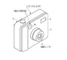
本発明を実施したデジタルカメラの外観を図1に示す。デジタルカメラ2は、そのカメラ本体3の前面に撮影レンズ4,ストロボ発光部5,照明光照射手段としての補助光照射部6の照射窓6aを設けてある。また、上面には撮影を指示するためのレリーズボタン7を設けてあり、背面にはLCD8(図2参照)と、ズームボタン9等の各種の操作部材を設けてある。
An appearance of a digital camera embodying the present invention is shown in FIG. The
撮影レンズ4は、ズームタイプになっており、ズームボタン9の操作によって、最も焦点距離を長くした望遠端と、最も焦点距離を短くした広角端との間で焦点距離が変化する。また、この撮影レンズ4は、焦点距離に応じて焦点距離と有効口径の比であるFナンバ(開放F値)が変化し、焦点距離が長くなるほどFナンバーが大きくなる。
The taking
レリーズボタン7は、半押しと、この半押しからさらに押し込んだ全押しとの2段操作になっている。撮影モード下で、レリーズボタン7を押圧操作していないときには、撮影範囲内の被写体像がLCD8に連続的に表示される、いわゆるスルー画像の表示が行われる。
The
レリーズボタン7が半押しとなると、静止画撮影のために、被写体輝度を測定し、その被写体輝度に応じたシャッタ速度,絞り値を決定する静止画用AE処理と、被写体に撮影レンズ4のピントを合致させるAF処理とを含む準備処理を行う。また、照射窓6aからAF補助光を照射してAF処理を行う場合には、静止画用AE処理の後にAF用AE処理を行ってからAF処理を行う。
When the
準備処理の後に静止画撮影処理を行う。この静止画撮影処理では、レリーズボタン7がさらに押し込まれて全押しとなると、静止画用AE処理で決定された静止画用のシャッタ速度と絞り値とを用いて静止画の撮影を行う。この静止画撮影処理で得られる静止画が画像データに変換されて、着脱自在なメモリカード10(図2参照)に記録される。
A still image shooting process is performed after the preparation process. In this still image shooting process, when the
なお、レリーズボタン7を一度の押圧操作で全押しにした場合や、一段操作のレリーズボタン7を押圧操作した場合にも、静止画用AE処理,AF用AE処理,AF処理を順次に行うように構成することができる。
It should be noted that even when the
ストロボ発光部5は、被写体輝度が不足している場合に、静止画の露光に同期してストロボ光を被写体に向けて照射する。補助光照射部6は、被写体輝度が所定レベル以下である場合に、AF処理に必要な十分な被写体輝度を確保するために照射窓6aから被写体に向けてAF補助光を照射する。
The stroboscopic
なお、照明光照射手段としてAF専用に設けた補助光照射部6を用いているが、照明光照射手段としては、これに限られるものではなく、他の目的で設けた光源装置を照明光照射手段として用いてもよい。例えばストロボ装置をAF処理のために発光させてもよく、暗い場所での撮影者のフレーミングを容易にするための光を照射する光源装置をAF処理のために点灯させてもよい。
Although the auxiliary
図2に上記デジタルカメラ2の構成を示す。システム制御部11は、レリーズボタン7やズームボタン9等からなる操作部12からの操作信号に基づいて、デジタルカメラ2の各部を制御する。このシステム制御部11には、ROM11a,RAM11bを接続してあり、ROM11aにはシステム制御部11が各部を制御するためのプログラムやパラメータを書き込んであり、RAM11bには処理に必要なデータ等が一時的に書き込まれる。
FIG. 2 shows the configuration of the
撮影レンズ4の背後にイメージセンサ13を配してあり、撮影レンズ4を透過した被写体光がイメージセンサ13の受光面に入射する。撮影レンズ4には、撮影レンズ4の焦点距離を調節するズーム機構14,ピントを調節するためのフォーカス機構15,イメージセンサ13への入射光量を調節するための絞り機構16を組み込んである。
An
ズーム機構14は、ズームボタン9の操作に応じて撮影レンズ4を構成する変倍レンズ14aを撮影レンズ4の光軸方向に移動して焦点距離の変更を行うものであり、変倍レンズ14aの他に、これを移動させるパルスモータやモータドライバ等で構成される。変倍レンズ14aは、撮影レンズ4の望遠端に対応した望遠変倍位置と広角端に対応した広角変倍位置との間で移動される。
The
撮影レンズ4は、最短撮影距離と無限遠との間の撮影距離範囲にある被写体に対してピントを合致できるようにされている。フォーカス機構15は、フォーカスレンズ15aの他に、これを移動させるパルスモータやモータドライバ等で構成されており、フォーカスレンズ15aを撮影レンズ4の光軸方向に移動することにより、撮影距離範囲の被写体に対してピントを合致させる。なお、ピントを調節するための構成は、種々の構成を採用することができ、複数のレンズを移動させるものであってもよい。
The taking
このデジタルカメラ2では、山登り方式を用いたコントラスト検出方式のオートフォーカスを採用しており、周知のようにコントラストのピークは、その前後の数ステップ分のレンズ位置におけるコントラスト変化に基づいて検出する。このため、最短撮影距離に対応した最短レンズ位置と無限遠に対応した無限遠レンズ位置のフォーカスレンズ15aの各レンズ位置についても、その前後のコントラストを取得するする必要がある。
This
そこで、最短レンズ位置よりもさらに数ステップ分だけ近距離側に移動したレンズ位置に、最短撮影距離の合焦の有無を検出するための移動開始位置としての近距離側レンズ端(移動端)を設定し、また無限遠レンズ位置よりもさらに数ステップ分だけ遠距離方向に移動したレンズ位置に、最も遠距離側の合焦の有無を検出するための移動開始位置としての遠距離側レンズ端(移動端)を設定して、これら近距離側レンズ端と遠距離側レンズ端との間でフォーカスレンズ15aが移動可能としてある。
Therefore, a short-distance lens end (moving end) as a movement start position for detecting whether or not the shortest shooting distance is in focus at a lens position that has moved further by a few steps than the shortest lens position. The far-end lens end (set as the movement start position for detecting the presence or absence of focusing on the farthest side to the lens position that has been set and moved in the far direction by several steps further than the infinity lens position ( The moving end) is set, and the
なお、位相差検出方式によって合焦位置を検出するように、合焦位置であることがその1つのレンズ位置からわかるような場合には、最短撮影距離の合焦の有無を検出するための移動開始位置として最短レンズ位置を近距離側レンズ端とし、最も遠距離側の合焦の有無を検出するための移動開始位置を無限遠レンズ位置とすればよい。 In addition, when detecting the in-focus position by the phase difference detection method, when the in-focus position can be known from the one lens position, the movement for detecting the presence / absence of in-focus at the shortest shooting distance The shortest lens position may be set as the short-distance side lens end as the start position, and the movement start position for detecting the presence or absence of focusing on the longest distance side may be set as the infinity lens position.
上述のフォーカス機構15には、フォーカスレンズ15aの位置を検出するレンズ位置検出手段15bを設けてある。このレンズ位置検出手段15bは、例えばフォーカスレンズ15aを駆動するパルスモータに供給される駆動パルスの個数とパルスモータの回転方向とに基づきフォーカスレンズ15aの位置を検出し、そのレンズ位置の情報をシステム制御部11に送る。システム制御部11は、このレンズ位置の情報をAF処理の際のフォーカスレンズ15aの駆動制御に用いる。
The
レンズ位置の検出は、上記の他に種々の手法を採用することができる。例えば、撮影レンズ4の温度特性によって駆動パルスの個数だけでは正確にレンズ位置を検出できない場合には、サーミスタを撮影レンズ4に取り付けて、この撮影レンズ4の温度に基づいてレンズ位置を補正してもよい。また、駆動パルスの個数で位置の制御を行わないリニアアクチュエータを用いる場合には、例えばホール素子を用いてレンズ位置を検出してもよい。
In addition to the above, various methods can be used for detecting the lens position. For example, if the lens position cannot be detected accurately only by the number of drive pulses due to the temperature characteristics of the
絞り機構16は、撮影レンズ4の光軸上に絞り開口を形成する絞り羽根16aやこれを駆動するアクチュエータ等から構成してあり、絞り開口の開口径を増減することにより、イメージセンサ13に入射する光量を調節する。
The
イメージセンサ13は、CCD型のものを用いており、その受光面に多数の受光素子が設けられている。このイメージセンサ13は、タイミングジェネレータ17からの各種駆動信号により駆動され、各受光素子で被写体光をその光量に応じた電荷に変換して蓄積し、その蓄積した電荷をアナログの画像信号に変換して出力する。これにより、露光した被写体像を電気的な信号に変換している。なお、イメージセンサ13としては、CCD型に限るものではなく、MOS型等でもよい。
The
イメージセンサ13は、電荷蓄積時間(露光時間)を調節する電子シャッタ機能を有している。この電子シャッタ機能は、タイミングジェネレータ17から入力される電子シャッタパルスの入力によってそれまでに蓄積した電荷を掃き出して消去することにより、フレーム期間中の電荷蓄積時間を調節する。この電子シャッタパルスのフレーム期間中の入力期間を調節することで、露光時間すなわち電子シャッタのシャッタ速度を調節することができる。この例では、このイメージセンサ13の電子シャッタのシャッタ速度と絞り機構16の絞り値との組み合わせで露出値が決まる。
The
タイミングジェネレータ17は、所定のタイミングで各種動作を行うための各種のパラメータがシステム制御部11によって設定され、イメージセンサ13を駆動するための駆動信号や各部を同期動作させるための同期信号等を発生する。タイミングジェネレータ17に設定するパラメータにより、イメージセンサ13の電子シャッタのシャッタ速度や、イメージセンサ13が電荷の蓄積、電荷の読出しを繰り返し行う際のフレームレートを変更することができる。なお、この例におけるタイミングジェネレータ17は、パラメータが設定された次のフレーム期間にその設定内容が有効になるものを用いている。
The timing generator 17 is set with various parameters for performing various operations at a predetermined timing by the
イメージセンサ13からの画像信号は、アナログ信号処理部18に送られる。アナログ信号処理部18は、CDS回路,AMP回路から構成してあり、相関二重サンプリング,画像信号の増幅をイメージセンサ13の電荷読み出しに同期して行う。A/D変換器19は、アナログ信号処理部18からの画像信号を画像データに変換して出力する。
The image signal from the
A/D変換器19からの画像データは、画像入力コントローラ20に送られる。画像入力コントローラ20は、バス21への画像データの入力を制御する。バス21には、システム制御部11,画像処理部22,圧縮伸張部23,AF検出部24,AE検出部25,メディアコントローラ26,内部メモリ27,VRAM28が接続されており、これら各部はバス21を介してシステム制御部11に制御されるとともに、相互間でデータの授受が可能にしてある。
Image data from the A /
画像処理部22は、画像データに対して、色補間,γ補正,ホワイトバランス補正,YC変換等の所定の画像処理を行う。圧縮伸張部23は、メモリカード10に記録すべき画像データを所定の圧縮形式、例えばJPEG形式によってデータ圧縮し、またメモリカード10から読み出した画像データのデータ伸張を行う。
The
AF検出部24は、システム制御部11とともに第1,第2合焦制御手段を構成している。このAF検出部24は、撮影レンズ4のピント合せのために、画像入力コントローラ20からの画像データを用いて、撮影画面内に予め設定されているAEAF検出領域から高周波成分を抽出し、その高周波成分を積算したAF評価値をシステム制御部11に出力する。システム制御部11は、AF評価値に基づいてAEAF検出領域内の被写体に撮影レンズ4のピントを合致させるAF処理を行う。
The
AE検出部25は、イメージセンサからの画像信号に基づいて被写体の輝度を検出する輝度検出手段であり、画像入力コントローラ20からの画像データに基づいて、AEAF検出領域についての被写体輝度の検出を行う。検出した被写体輝度は、システム制御部11に送られる。システム制御部11は、被写体輝度に基づいてイメージセンサ13のシャッタ速度,絞り装置16の絞り値を決定する。
The
この例では、AEAF検出領域として、撮影画面内に予め設定した領域を用いているが、画像データに基づいて撮影画面内から人物の顔を特定し、その特定した顔の領域をAEAF検出領域に割り当てるように構成してもよい。 In this example, an area set in advance in the shooting screen is used as the AEAF detection area. However, a person's face is specified from the shooting screen based on the image data, and the specified face area is used as the AEAF detection area. You may comprise so that it may allocate.
メディアコントローラ26は、メモリカード10のデータの書き込み及び読み出しを制御する。記録すべき画像データは、画像処理部22,圧縮伸張部23によって各種処理が施されてから、メディアコントローラ26に送られて、メモリカード10に書き込まれる。また、再生時には、メディアコントローラ26によってメモリカード10から画像データが読み出され、圧縮伸張部23によってデータ伸張が行われる。
The
内部メモリ27は、画像処理部22で処理中の画像データ等が一時的に書き込まれるワークメモリとして用いられる。また、VRAM28には、LCD8に表示すべき画像データが書き込まれる。D/A変換器31は、所定の周期でVRAM28上の画像データを読み出すことにより、画像データに基づいた画像をLCD8に表示する。
The
撮影モード下では、イメージセンサ13による露光が繰り返され、画像処理が施された画像データが次々にVRAM28に書き込まれる。これにより、スルー画像がLCD8に表示される。また、再生モード下では、メモリカード10から読み出されてデータ伸張された画像データがVRAM28に書き込まれるから、メモリカード10に記録されている撮影済みの画像がLCD8に表示される。
Under the shooting mode, exposure by the
スルー画像の表示中では、システム制御部11の制御により、所定の間隔でフォーカスレンズ15aを微動するなどして、AF評価値に基づいてコントラストが最大となる合焦位置の検出を行い、検出した合焦位置にフォーカスレンズ15aを移動させて被写体に合焦するようにしている。なお、このようなピント調節の手法は、これまでのデジタルカメラと同様な手法を用いることができ、この例においてもそのように構成してある。
During the display of the through image, the
ストロボ装置32は、ストロボ発光部5の内部に組み込まれたストロボ放電管やそれを発光させるための回路から構成されており、システム制御部11の制御下でストロボ光を出力する。
The
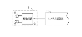
補助光照射部6は、光源としてのLED33,このLED33を駆動する駆動回路34から構成してある。駆動回路34は、システム制御部11に制御されて被写体輝度が一定レベル以下の場合にLED33を一定の明るさで点灯する。LED33からの光は、AF補助光として照射窓6aから被写体に向けて照射される。
The auxiliary
AF補助光の照射エリアは、AEAF検出領域をカバーするように照射される。また、AF補助光を照射するか否かの判断基準となる被写体輝度の一定レベルは、例えば被写体像のコントラストを十分な精度で検出できるか、すなわち十分に正確に合焦位置を検出できるかどうかを基準に決定すればよく、ストロボ光の要否を判断する基準と同じにする必要はない。 The irradiation area of the AF auxiliary light is irradiated so as to cover the AEAF detection area. In addition, the constant level of the subject brightness that is a criterion for determining whether or not to irradiate the AF auxiliary light is, for example, whether the contrast of the subject image can be detected with sufficient accuracy, that is, whether the in-focus position can be detected with sufficient accuracy. It is not necessary to be the same as the standard for determining whether or not the strobe light is necessary.
静止画用AE処理は、静止画を撮影する際に用いる露出値を決定するための処理であり、レリーズボタン7の半押しに応答して行われる。この静止画用AE処理では、イメージセンサ13のダイナミックレンジが狭いため、種々想定される撮影シーンの明るさ範囲を複数の測定範囲に分割して測定し、各測定範囲がイメージセンサ13によって測定可能な範囲となるようにしてある。
The still image AE process is a process for determining an exposure value used when shooting a still image, and is performed in response to a half-press of the
AF用AE処理は、AF補助光を照射した状態でAF処理を行うための露出値を決定する処理であり、静止画用AE処理で測定した被写体輝度が一定レベル以下の場合に実行される。このAF用AE処理は、AF補助光を被写体に向けて照射した状態におけるイメージセンサ13の露光から得られる画像データに基づいて、AEAF検出領域の被写体輝度を検出し、その被写体輝度を露出値としてシャッタ速度、絞り値を決定する。
The AF AE process is a process for determining an exposure value for performing the AF process in a state where the AF auxiliary light is irradiated, and is executed when the subject luminance measured in the still image AE process is equal to or lower than a certain level. This AF AE process detects the subject brightness in the AEAF detection area based on the image data obtained from the exposure of the
上記のAF用AE処理では、AF補助光を照射することにより測定すべき被写体輝度が上昇することが予想される。このため、システム制御部11は、静止画用AE処理で求めた露出値をプラス側にシフトした露出値を用いて露光を実行させる。
In the AF AE process described above, it is expected that the subject brightness to be measured increases by irradiating the AF auxiliary light. Therefore, the
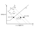
図3に示すように、静止画用AE処理によって求められた露出値(被写体輝度)をEV1とした場合、この設定された露出値EV1を挟んでイメージセンサ13の性能等から決まる一定の測定可能範囲の被写体輝度が実際に測定可能な輝度範囲となる。AF用AE処理では、AF補助光の照射によって予想される被写体輝度の上昇を考慮して、露出値EV1よりもプラス側にシフト量ΔEVだけシフトした露出値EV2を用いて露光を行う。このようにしてAF用AE処理時の測定可能な被写体輝度の範囲をプラス側にシフトし、AF補助光の照射に対応できるようにする。
As shown in FIG. 3, when the exposure value (subject brightness) obtained by the AE process for still images is EV1, a constant measurement that is determined by the performance of the
シフト量ΔEVの決定には、AF補助光の光量と種々のパラメータとを用いた様々な手法により被写体輝度の推定される増加分として求めることができる。例えば、AF補助光が有効に照射されかつ通常想定される撮影距離に規定のAF補助光を照射した場合の輝度増加分をシフト量ΔEVとしてもよい。また、前述のように顔の領域を特定しその顔の領域をAEAF検出領域とする場合では、顔の領域の大きさ(面積)に基づいて概略的に撮影距離を推定できるから、AF補助光の光量とその推定した撮影距離に基づいてシフト量ΔEVを求めてもよく、これに加えて顔の反射率を加味するようにしてもよい。なお、イメージセンサ13のダイナミックレンジを考慮して、露出値EV2としたときに、静止画用AE処理で測定した被写体輝度EV1が測定可能な範囲内となるシフト量ΔEVとするのがよい。
The shift amount ΔEV can be determined as an estimated increase in subject brightness by various methods using the amount of AF auxiliary light and various parameters. For example, the amount of increase in luminance when the AF auxiliary light is effectively irradiated and the specified AF auxiliary light is irradiated at a normally assumed shooting distance may be used as the shift amount ΔEV. Further, when the face area is specified as described above and the face area is set as the AEAF detection area, the shooting distance can be roughly estimated based on the size (area) of the face area. The amount of shift ΔEV may be obtained based on the amount of light and the estimated shooting distance, and in addition to this, the reflectance of the face may be taken into account. In consideration of the dynamic range of the
AF処理では、AF補助光を照射しない場合には静止画AE処理で決定された露出値を用いて、またAF補助光を照射する場合にはAF用AE処理で決定された露出値を用いて、詳細を後述するAF処理を行う。 In the AF process, the exposure value determined in the still image AE process is used when the AF auxiliary light is not irradiated, and the exposure value determined in the AF AE process is used when the AF auxiliary light is irradiated. Then, AF processing, which will be described later in detail, is performed.
AF用AE処理とAF処理とで同じ絞り値を用いることにより、AF用AE処理からAF処理に移行する際の絞り値変更に伴うタイムロスをなくしている。また、静止画の撮影に用いる絞り値、すなわち静止画用AE処理で決定される絞り値をAF処理に用いることにより、AF処理から静止画の撮影に移行する際のタイムロスをなくしている。なお、このようにすることにより、AF用AE処理に用いられる絞り値にいついても、静止画の撮影に用いられる絞り値が用いられる。 By using the same aperture value in the AF AE process and the AF process, the time loss associated with the change in aperture value when shifting from the AF AE process to the AF process is eliminated. Further, by using the aperture value used for still image shooting, that is, the aperture value determined in the still image AE processing, for AF processing, time loss when shifting from AF processing to still image shooting is eliminated. By doing so, the aperture value used for still image shooting is used whenever the aperture value used for AF AE processing is used.
具体的には、絞り機構16を静止画用AE処理で決定された絞り値に駆動したのち、AF用AE処理では、シャッタ速度をシフト量ΔEVだけ高速側にシフトして露光を行う。また、AF用AE処理で決定される露出値に対してもシャッタ速度を変化させることにより対応する。
Specifically, after the
図4に示すように、静止画用AE処理で求められた露出値EV1に対して、所定のプログラム線PLによりシャッタ速度TV1、絞り値AV1が決定された場合、AF用AE処理では、絞り値AV1を固定したまま、シャッタ速度を高速側にシフト量ΔEVでシフトしたシャッタ速度TV2(=TV1+ΔEV)とする。また、AF用AE処理において測定された被写体輝度に対する適正な露出値をEV3とすれば、AF処理では、絞り値AV1の下で露出値EV3となるシャッタ速度TV3(=EV3―AV1)を用いる。 As shown in FIG. 4, when the shutter speed TV1 and the aperture value AV1 are determined by a predetermined program line PL with respect to the exposure value EV1 obtained in the still image AE process, the aperture value is determined in the AF AE process. The shutter speed TV2 (= TV1 + ΔEV) is obtained by shifting the shutter speed to the high speed side by the shift amount ΔEV while AV1 is fixed. If an appropriate exposure value for the subject luminance measured in the AF AE process is EV3, the AF speed uses a shutter speed TV3 (= EV3−AV1) that becomes the exposure value EV3 below the aperture value AV1.
また、AF処理を高速化するために、静止画AE処理またはAF用AE処理で決定されたシャッタ速度に応じて、AF処理の際のイメージセンサ13のフレームレートを切り換える。AF処理用のフレームレートには、異なる例えば3種類のフレームレートが用意されており、設定されるシャッタ速度でイメージセンサ13を駆動することができる最もレートの高いフレームレートをシステム制御部11が選択し、その選択したフレームレートでイメージセンサ13を駆動するようにタイミングジェネレータ17にパラメータを設定する。これにより、AF処理中のフレーム期間の長さを短くしてピント合せに必要な時間を短縮させている。
Further, in order to speed up the AF process, the frame rate of the
なお、この例におけるAF処理では、イメージセンサ13に電子シャッタパルスを入力している期間に撮影レンズ4のレンズ位置の移動を行って同一のフレーム期間中にレンズ位置の移動と露光とを行うようにしている。このため、その撮影レンズ4のレンズ位置の移動に要する時間も考慮してフレームレートが選択される。
In the AF process in this example, the lens position of the photographing
また、絞り値を固定したままシャッタ速度を変えるようにしているが、撮影感度が可変の場合には、シャッタ速度の他に撮影感度を変化させてもよい。また、AF用AE処理で決定してAF処理で用いる露出値EV3は、AF処理において良好に合焦位置を検出できる値として決定することができる。 In addition, the shutter speed is changed while the aperture value is fixed. However, when the photographing sensitivity is variable, the photographing sensitivity may be changed in addition to the shutter speed. Further, the exposure value EV3 determined in the AF AE process and used in the AF process can be determined as a value with which the in-focus position can be detected satisfactorily in the AF process.
前述のようにシステム制御部11は、AEAF検出領域の被写体に撮影レンズ4のピントを合致させるAF処理を行うものであり、第2の合焦制御手段となっている。スルー画像を表示している間のピント調節は、大きな移動ステップでフォーカスレンズを調節したり、所定の間隔でピント調節を行っているため、レリーズボタン7の操作時にはピントが合致していない、あるいは精度よく合致していない状態となって可能性がある。このため、レリーズボタン7の操作に応答してAF処理を行う。
As described above, the
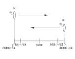
AF処理は、前述のように山登り方式のコントラスト検出方式を採用している。AF処理には、通常AF処理と、高速AF処理とがあり、AF補助光を照射しない場合には通常AF処理を、AF補助光を照射する場合には高速AF処理を行うが、いずれの場合にも高速AF処理を行うように構成してもよい。さらに、被写体にピントが合致するフォーカスレンズ15aの合焦位置を検出する際の動作として、フォーカスレンズ15aの移動開始位置と移動方向の異なる第1AF動作と、第2AF動作とがある。第1AF動作は、図5(a)に示すように、近距離側レンズ端から遠距離レンズ端に向けてフォーカスレンズ15aをステップ移動する動作である。また、第2AF動作は、図5(b)に示すように、遠距離側レンズ端から近距離レンズ端に向けてフォーカスレンズ15aをステップ移動する動作である。
As described above, the AF processing employs the hill-climbing contrast detection method. AF processing includes normal AF processing and high-speed AF processing. When AF auxiliary light is not irradiated, normal AF processing is performed. When AF auxiliary light is irradiated, high-speed AF processing is performed. Alternatively, high-speed AF processing may be performed. Furthermore, there are a first AF operation and a second AF operation in which the movement start position of the
通常AF処理、高速AF処理のいずれでも、フォーカスレンズ15aがステップ移動するごとに、イメージセンサ13での露光を行ってAF評価値を取得し、AF評価値が増大から減少に転じるレンズ位置をコントラストがピークとなる合焦位置として検出し、その検出直後にフォーカスレンズ15aを合焦位置に移動してセットする。
In both the normal AF process and the high-speed AF process, every time the
通常AF処理では、例えば第1AF動作を用いて合焦位置の検出を行うが、第2AF動作を用いて合焦位置の検出を行ってもよい。高速AF処理では、合焦時間を短くするために、フォーカスレンズ15aのレンズ位置に応じて合焦の検出するためのフォーカスレンズ15aの移動開始位置と移動方向として、第1AF動作と第2AF動作のいずれか1つのAF動作を選択する。
In the normal AF process, for example, the focus position is detected using the first AF operation, but the focus position may be detected using the second AF operation. In the high-speed AF process, in order to shorten the focusing time, the first AF operation and the second AF operation are performed as the movement start position and the movement direction of the
システム制御部11は、フォーカスレンズ15aのレンズ位置が中間レンズ位置と同じかそれよりも近距離側にある場合、すなわちレンズ位置が遠距離側の移動端よりも近距離側の移動端に近い場合には、第1AF動作を選択する。これにより、フォーカスレンズ15aが移動開始位置に移動するための移動量と、近距離にあると推定されるAEAF検出領域内の被写体に対する合焦位置に達するまでの移動量を小さくし、合焦時間を短縮する。また、フォーカスレンズ15aのレンズ位置が中間レンズ位置よりも遠距離側にある場合、すなわちレンズ位置が近距離側の移動端よりも遠距離側の移動端に近い場合には、第2AF動作を選択し、移動開始位置に移動するための移動量と遠距離にあると推定されるAEAF検出領域内の被写体に対する合焦位置に達するまでの移動量を小さくし、合焦時間を短縮する。
When the lens position of the
中間レンズ位置は、無限遠レンズ位置と最短レンズ位置との中間のレンズ位置であり、この中間レンズ位置よりも遠距離側であれば無限遠レンズ位置への移動量が最短レンズ位置への移動量よりも小さく、逆に中間レンズ位置よりも近距離側であれば最短レンズ位置への移動量が無限遠レンズ位置への移動量よりも小さいことを意味する。 The intermediate lens position is an intermediate lens position between the infinity lens position and the shortest lens position. If the distance is farther than the intermediate lens position, the movement amount to the infinity lens position is the movement amount to the shortest lens position. If it is smaller than the intermediate lens position, it means that the moving amount to the shortest lens position is smaller than the moving amount to the infinity lens position.
なお、フォーカスレンズ15aを連続的に移動させるのではなく予め決められたレンズ位置にステップ的に移動させる場合には、無限遠レンズ位置及び最短レンズ位置へのステップ数が同じとなるレンズ位置を中間レンズ位置としてもよい。また、このようなステップ数とレンズの実際の移動量(駆動に必要な駆動パルス数)との両方を考慮して、短時間で合焦位置に到達するように中間レンズ位置を決めてもよい。
When the
次に上記構成の作用について、図6ないし図9を参照しながら説明する。撮影モード下でレリーズボタン7を操作していない場合には、一定の周期でイメージセンサ13による露光が繰り返し行われ、LCD8にスルー画像の表示が行われている。このスルー画像の表示を行っている間では、これまでのデジタルカメラと同様に、撮影距離の変化に追従して撮影レンズ4のピント合わせが行われる状態となっている。すなわち、被写体にピントが合致するようにフォーカスレンズ15aのレンズ位置が継続的に調節される。
Next, the operation of the above configuration will be described with reference to FIGS. When the
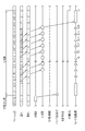
レリーズボタン7を半押しとすると、これ応答して、その時点のフォーカスレンズ15aのレンズ位置がレンズ位置検出手段15bからシステム制御部11に送られる。また、レリーズボタン7の半押しに応答して、被写体輝度EV1を測定するための静止画用AE処理が開始される。レリーズボタン7が半押しとされた直後のフレーム期間を1番目とすると、この1番目のフレーム期間中に第1回の測光のシャッタ速度を含むパラメータがシステム制御部11によってタイミングジェネレータ17に設定される。
When the
そして、2番目のフレーム期間となると、絞り機構16が第1回の測光のための絞り値とされてから、電子シャッタパルスの入力が停止されて、イメージセンサ13による露光Ea1が行われる。このときのイメージセンサ13の駆動は、1番目のフレーム期間中にタイミングジェネレータ17に設定されたパラメータに基づくものとなっている。
In the second frame period, the
3番目のフレーム期間となると、露光Ea1によってイメージセンサ13に蓄積された各電荷の転送(読出し)が開始されて画像信号が出力される。この画像信号は、アナログ信号処理部18,A/D変換器19を介して画像データに変換されてから、画像入力コントローラ20を介してAE検出部25に送られる。
In the third frame period, the transfer (reading) of each charge accumulated in the
また、露光Ea1が行われている2番目のフレーム期間には、第2回の測光のためのパラメータがタイミングジェネレータ17に設定され、3番目のフレーム期間には、絞り機構16が第2回の測光の絞り値とされてから、イメージセンサ13による露光Ea2が行われる。そして、4番目のフレーム期間に露光Ea2による画像信号が出力され、その画像データがAE検出部25に送られる。
In the second frame period during which exposure Ea1 is performed, parameters for the second photometry are set in the timing generator 17, and in the third frame period, the
同様な手順により、3回の測光のための露光Ea3が4番目のフレーム期間に行われ、5番目のフレーム期間にその画像データがAE検出部25に送られる。また、5番目のフレーム期間中にスメア成分を検出する露光Ea4を行う。この露光Ea4では露光Ea3と同じ条件でイメージセンサ13による電荷蓄積を行うが、その電荷を垂直転送路に移動させることなく、6番目のフレーム期間中に垂直,水平転送路内の電荷を転送する。これにより、被写体像の成分を含まないスメア成分だけの画像データをAE検出部25に取り込む。
By the same procedure, exposure Ea3 for photometry three times is performed in the fourth frame period, and the image data is sent to the
上記のようにして各画像データの取得が完了すると、その後の7番目のフレーム期間には、各測光で得られる画像データに基づいてAEAF検出領域の被写体輝度EV1がAE検出部25によって求められ、この被写体輝度EV1がシステム制御部11に送られて静止画を撮影するための露出値EV1とされる。なお、被写体輝度EV1を求める際には、露光Ea3の画像データをスメア成分の画像データに基づいて補正したものが用いられる。
When the acquisition of each image data is completed as described above, the subject brightness EV1 in the AEAF detection area is obtained by the
露出値EV1は、所定のプログラム線に基づいてシャッタ速度TV1と絞り値AV1との組み合せに変換され、続く8番目のフレーム期間に絞り値AV1となるように絞り機構16が駆動される。また、被写体輝度EV1からAF補助光の発光の要否がシステム制御部11によって判定される。
The exposure value EV1 is converted into a combination of the shutter speed TV1 and the aperture value AV1 based on a predetermined program line, and the
例えば、被写体輝度EV1が一定レベル以下の場合には、AF補助光が必要と判定され、AF補助光の光量と所定のパラメータとを用いてシフト量ΔEVがシステム制御部11で算出され、静止画用AE処理で決定されたシャッタ速度TV1をシフト量ΔEVだけ増加させたシャッタ速度TV2が決定される。
For example, when the subject brightness EV1 is equal to or lower than a certain level, it is determined that AF auxiliary light is necessary, and the shift amount ΔEV is calculated by the
シャッタ速度をシフト量ΔEVでシフトした結果、そのシャッタ速度TV2がイメージセンサ13の最も高速なシャッタ速度TVmaxを超える場合には、AF補助光を用いなくてもある程度の明るさがあるものとして、シャッタ速度のシフトをキャンセルしAF補助光を照射しない場合と同じ処理を行う。なお、この場合に、シャッタ速度TV2がシャッタ速度TVmax以下となるように絞り機構16を駆動して絞り込んでAF用AE処理を継続させてもよく、撮影感度を下げてAF用AE処理を継続させてもよい。
If the shutter speed TV2 exceeds the fastest shutter speed TVmax of the
8番目のフレーム期間となってAF用AE処理が開始されると、上述のように絞り値AV1とされるとともに、シャッタ速度TV2を含むパラメータがタイミングジェネレータ16に設定される。また、LED33が点灯されてAF補助光の照射が開始される。
When the AF AE process is started in the eighth frame period, the aperture value AV1 is set as described above, and parameters including the shutter speed TV2 are set in the
9番目のフレーム期間には、絞り値AV1,シャッタ速度TV2の下で露光Eb1が行われ、その露光Eb1の結果が10番目のフレーム期間中に画像信号として出力される。そして、11番目のフレーム期間中に露光Eb1の画像データから被写体輝度EV3がAE検出部25によって求められ、AF補助光を照射した状態でのAEAF検出領域に対する適切な露出値EV3とされる。
In the ninth frame period, the exposure Eb1 is performed under the aperture value AV1 and the shutter speed TV2, and the result of the exposure Eb1 is output as an image signal during the tenth frame period. Then, the subject luminance EV3 is obtained from the image data of the exposure Eb1 during the eleventh frame period by the
露出値EV3と絞り値AV1とから、AF処理で用いるシャッタ速度TV3がシステム制御部11によって求められ、12番目のフレーム期間となってAF処理が開始されると、図9に示されるように、そのシャッタ速度TV3を含むパラメータがタイミングジェネレータ17に設定される。このときに、フレームレートのパラメータとしては、シャッタ速度TV3でイメージセンサ13を駆動することができる最もレートの高いフレームレートのものが設定される。
When the shutter speed TV3 used in the AF process is obtained from the exposure value EV3 and the aperture value AV1, and the AF process is started in the 12th frame period, as shown in FIG. Parameters including the shutter speed TV3 are set in the timing generator 17. At this time, the frame rate parameter having the highest frame rate at which the
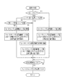
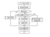
また、12番目のフレーム期間になると、AF処理が行われるが、AF補助光が照射されている場合であるので、図7に示す高速AF処理が行われる。高速AF処理が開始されると、システム制御部11によって、レリーズボタン7の半押しに応答して取得したフォーカスレンズ15aのレンズ位置が中間レンズ位置と比較される。
Also, when the twelfth frame period is reached, AF processing is performed, but since AF assist light is being irradiated, the high-speed AF processing shown in FIG. 7 is performed. When the high-speed AF process is started, the
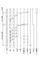
例えば、上記比較でフォーカスレンズ15aのレンズ位置が中間レンズ位置と同じかそれよりも近距離側にある場合には、第1AF動作が選択される。そして、第1AF動作が選択されると、移動開始位置が近距離側レンズ端となるため、12番目と13番目のフレーム期中にフォーカスレンズ15aが近距離側レンズ端にまで移動される。このフォーカスレンズ15aの移動後、14番目のフレーム期間になると、合焦位置を検出するための1回目の露光Ec1がイメージセンサ13で行われ、15番目のフレーム期間にその露光Ec1の結果が画像信号として出力され、16番目のフレーム期間中に、露光c1に基づくAEAF検出領域のAF評価値がAF検出部24からシステム制御部11に送られる。
For example, the first AF operation is selected when the lens position of the
また、15番目のフレーム期間には、フォーカスレンズ15aが近距離側レンズ端から1ステップ分だけ遠距離側レンズ端方向に移動される。そして、その移動完了後に2回目の露光Ec2が行われ、露光Ec2の画像信号が16番目のフレーム期間中に出力され、17番目のフレーム期間中にAF検出領域のAF評価値がシステム制御部11に送られる。
In the fifteenth frame period, the
さらに、16番目のフレーム期間には、フォーカスレンズ15aがさらに1ステップ分だけ遠距離側レンズ端方向に移動される。そして、その移動完了後に3回目の露光Ec3が行われて、17番目のフレーム期間中にその画像信号が出力され、18番目のフレーム期間中にAF評価値がシステム制御部11に送られる。以降、同様にして、フォーカスレンズ15aを1ステップずつ遠距離側レンズ端に向けて移動しながら露光を順次に行ってAF評価値を取得していく。
Further, in the 16th frame period, the
上記のようにAF評価値が入力されると、その都度、そのAF評価値とそれまでに取得した所定個数のAF評価値とがシステム制御部11で調べられ、AF評価値、すなわちコントラストが増大から減少に転じる合焦の有無のチェック、すなわち合焦位置が検出されたか否かが判断される。合焦位置が検出されない場合には、引き続きフォーカスレンズ15aを1ステップずつ移動させながら露光を順次に行ってAF評価値を取得していく。そして、合焦位置が検出されると、フォーカスレンズ15aのステップ移動が終了され、直ちにその合焦位置にフォーカスレンズ15aが移動される。
When an AF evaluation value is input as described above, each time the AF evaluation value and a predetermined number of AF evaluation values acquired so far are examined by the
例えば図9では、「n+3」番目のフレーム期間の露光「Ecn+3」から得られるAF評価値が「n+5」番目のフレーム期間中にシステム制御部11に入力された際の判断により、n番目のフレーム期間のレンズ位置Snでのコントラストがピークであり、レンズ位置Snが合焦位置と検出された場合を示している。そして、合焦位置を検出した直後の「n+6」番目と「n+7」番目のフレーム期間中にフォーカスレンズ15aを合焦位置であるレンズ位置Snに移動している。
For example, in FIG. 9, the nth frame is determined based on the determination when the AF evaluation value obtained from the exposure “Ecn + 3” in the “n + 3” th frame period is input to the
一方、フォーカスレンズ15aのレンズ位置が中間レンズ位置よりも遠距離側にある場合には、第2AF動作が選択される。第2AF動作が選択されたときには、遠距離側レンズ端が移動開始位置とされるため、12番目と13番目のフレーム期中にフォーカスレンズ15aが遠距離側レンズ端にまで移動される。この移動後、合焦位置を検出するための露光Ec1がイメージセンサ13で行われる。以降フォーカスレンズ15aを近距離側レンズ端に向けてステップ移動させながら露光を行い、AF評価値を取得し、第1AF動作が選択された場合と同様に合焦位置を検出する。そして、合焦位置の検出直後に、フォーカスレンズ15aがその合焦位置に移動される。
On the other hand, when the lens position of the
上記のように、このデシタルカメラ2では、フォーカスレンズ15aのレンズ位置に応じて第1、第2AF動作、すなわちフォーカスレンズ15aの移動開始位置と移動方向を選択して合焦位置の検出を行う。このため、フォーカスレンズ15aを移動開始位置に移動する移動量が小さく、またその移動開始位置から合焦位置までのフォーカスレンズ15aの移動量が小さいので、短い合焦時間でピント合わせを完了することができる。
As described above, the
また、フォーカスレンズ15aのレンズ位置に基づいて推測している被写体の遠近が実際と異なっていても、引き続きフォーカスレンズ15aを移動させながらAF評価値を取得して行くことで合焦位置を検出できるので、フォーカスレンズ15aを再度、他の移動開始位置に移動させる等、余分な移動が発生しないため合焦時間を長時間化させることがない。
Further, even when the perspective of the subject estimated based on the lens position of the
被写体輝度EV1が一定レベルよりも大きい場合には、AF補助光が不要と判定され、この場合には静止画用AE処理に続いて通常AF処理が行われる。この通常AF処理で合焦位置が検出されると、その合焦位置の検出直後に、フォーカスレンズ15aがその合焦位置に移動される。
If the subject brightness EV1 is greater than a certain level, it is determined that AF auxiliary light is unnecessary, and in this case, normal AF processing is performed following the still image AE processing. When the focus position is detected by the normal AF process, the
いずれの場合にも、フォーカスレンズ15aが合焦位置とされるとAF処理が完了し、LED33を消灯してから静止画撮影処理が開始され、レリーズボタン7が全押しとされるのを待つ待機状態となる。そして、待機状態中にレリーズボタン7が全押しとされると、絞り値AV1,シャッタ速度TV1で静止画のための露光が行われる。この露光で得られる画像データが画像処理部22による画像処理、圧縮伸張部23によるデータ圧縮を経てメディアコントローラ26に送られてメモリカード10に記録される。
In any case, when the
図10は、高速AF処理の際に、フォーカスレンズのレンズ位置と、照明光を照射していない状態と照射した状態との各被写体輝度の大小関係とに基づいてAF動作を選択する例を示すものである。なお、以下に説明する他は、上記実施形態と同様であり実質的に同じ部材には同一の符号を付してその説明を省略する。 FIG. 10 shows an example in which the AF operation is selected based on the lens position of the focus lens and the relationship between the luminance of each subject between the state where the illumination light is not irradiated and the state where it is irradiated during the high-speed AF processing. Is. In addition, except being demonstrated below, it is the same as that of the said embodiment, The same code | symbol is attached | subjected to the substantially same member, and the description is abbreviate | omitted.
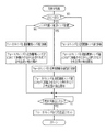
システム制御部11は、静止画用AE処理で測定した被写体輝度EV1をAF補助光を照射しない状態での被写体輝度とし、AF用AE処理で測定した被写体輝度EV3をAF補助光の照射した状態での被写体輝度としてそれぞれ用い、AF補助光の照射による被写体の輝度変化を調べる。被写体輝度EV3が被写体輝度EV1以上の場合(EV3≧EV1)には、AEAF検出領域内の被写体がAF補助光の照射により輝度が増大する程度の近距離にあり、フォーカスレンズ15aを近距離側レンズ端より遠距離レンズ端に向けて移動させることで早く合焦位置を検出できることが期待できるため第1AF動作を選択する。
The
一方、被写体輝度EV3が被写体輝度EV1よりも小さい場合(EV3<EV1)には、フォーカスレンズ15aのレンズ位置を境界レンズ位置と比較する。境界レンズ位置は、AF補助光を照射しても実質的に輝度上昇が見込まれない、すなわちAF補助光が有効に到達しない不達距離範囲の近距離端(この距離を境界撮影距離と称する)の被写体に合焦するフォーカスレンズ15aのレンズ位置に相当する位置である。なお、この境界レンズ位置、すなわち境界撮影距離は、例えば撮影レンズ4のズーミングによるFナンバーの変化、あるいは絞り機構16による絞り値の変化に応じて変化するため、中間レンズ位置よりも近距離側になったり、遠距離側になったりするため、境界レンズ位置と中間レンズ位置の位置関係は変化する。
On the other hand, when the subject brightness EV3 is smaller than the subject brightness EV1 (EV3 <EV1), the lens position of the
境界レンズ位置との比較において、フォーカスレンズ15aのレンズ位置が境界レンズ位置よりも遠距離側にある場合には、さらにフォーカスレンズ15aのレンズ位置を中間レンズ位置と比較する。この比較において、フォーカスレンズ15aのレンズ位置が中間レンズ位置よりも遠距離側にある場合には、フォーカスレンズ15aが無限遠レンズ位置(遠距離側レンズ端)に近いと判断し、第2AF動作を選択する。
In the comparison with the boundary lens position, when the lens position of the
また、中間レンズ位置との比較において、レンズ位置が中間レンズ位置と同じあるいはそれより近距離側と判断される場合には、中間的な撮影距離であると推測し、第3AF動作を選択する。同様に、被写体輝度EV3が被写体輝度EV1よりも小さい場合でレンズが境界レンズ位置よりも近距離側にあると判断された場合にも第3AF動作を選択する。 If the lens position is determined to be the same as or closer to the intermediate lens position in comparison with the intermediate lens position, the intermediate AF position is estimated and the third AF operation is selected. Similarly, the third AF operation is also selected when the subject brightness EV3 is smaller than the subject brightness EV1 and it is determined that the lens is closer to the boundary lens position.
第3AF動作は、図11に示すように、境界レンズ位置に対応して設定された境界用移動開始位置を移動開始位置として、フォーカスレンズ15aを遠距離側レンズ端に向けて移動させる動作となっている。境界用移動開始位置は、山登り方式を用いたコントラスト検出方式により、境界レンズ位置の合焦の有無を検出できるように、境界レンズ位置よりも数ステップ分だけ近距離側に移動したレンズ位置となっている。なお、合焦位置の検出方法によっては、境界レンズ位置を境界用移動開始位置としてよい。
As shown in FIG. 11, the third AF operation is an operation of moving the
上記のように、被写体輝度EV1,EV3の大小関係とレンズ位置とからAF動作を選択し、中間的な撮影距離であると判断した場合には第3AF動作を選択して合焦位置の検出の高速化を図っている。 As described above, the AF operation is selected from the relationship between the subject luminance values EV1 and EV3 and the lens position, and when it is determined that the shooting distance is an intermediate shooting distance, the third AF operation is selected to detect the focus position. We are trying to speed up.
なお、この例では、無限遠レンズ位置と最短レンズ位置との中間である中間レンズ位置を用いているが、この中間レンズ位置に代えて、境界レンズ位置と無限遠レンズ位置(または遠距離側レンズ端)との中間のレンズ位置を用いてもよい。また、その他のレンズ位置を用いることもできる。 In this example, an intermediate lens position that is intermediate between the infinity lens position and the shortest lens position is used. Instead of this intermediate lens position, the boundary lens position and the infinity lens position (or the long-distance lens) are used. An intermediate lens position with respect to (end) may be used. Other lens positions can also be used.
境界レンズ位置が固定的に中間レンズ位置よりも遠距離側にある場合には、図12に示すように処理してもよい。この例では、被写体輝度EV3が被写体輝度EV1よりも小さい場合(EV1>EV3)に、フォーカスレンズ15aのレンズ位置を境界レンズ位置と比較し、レンズ位置が境界レンズ位置よりも近距離側にあるときには第3AF動作とし、レンズ位置が境界レンズ位置と同じかそれよりも遠距離側にあるときには第2AF動作としている。被写体輝度EV3が被写体輝度EV1以上の場合(EV3≧EV1)には、第1AF動作としている。
When the boundary lens position is fixedly farther than the intermediate lens position, processing may be performed as shown in FIG. In this example, when the subject luminance EV3 is smaller than the subject luminance EV1 (EV1> EV3), the lens position of the
上記図10、図12に示す例において、AF補助光の照射が必要でない場合にも、AF補助光を照射して被写体輝度EV1、EV3を取得すれば、同様な手順で合焦位置の検出を行うことができる。 In the example shown in FIGS. 10 and 12, even when AF auxiliary light irradiation is not necessary, if the subject brightness EV1 or EV3 is obtained by irradiating AF auxiliary light, the focus position is detected in the same procedure. It can be carried out.
上記図10,図12に示す例においては、フォーカスレンズ15aのレンズ位置が境界レンズ位置よりも近距離側にあるときであっても、AF補助光の照射により被写体輝度が増大しない(EV1>EV3)場合には、第3AF動作を選択している。これは、AF補助光を照射する場合は、被写体輝度がある程度低く、暗い環境であるので、このような環境下においては、コントラスト値に基づいたフォーカスレンズ15aのレンズ位置に示される撮影距離よりも、AF補助光の照射による被写体の輝度変化量に基づいて判断される撮影距離の方がより信頼性が高いため、このように制御することが的確で高速な合焦位置の検出を行えるという理由に基づくものである。
In the example shown in FIGS. 10 and 12, even when the lens position of the
ところで、フォーカスレンズ15aのレンズ位置をAF補助光の照射による被写体の輝度変化量よりも優先して取り扱い、高速で確実な合焦位置の検出を行うように構成することもできる。図13に示す例では、被写体輝度が増大する場合には、図10,図12に示す例と同様に第1AF動作を選択し、被写体輝度が増大せず、かつフォーカスレンズ15aが境界レンズ位置よりも遠距離側にある場合には、第2AF動作を選択する。他方、被写体輝度が増大せず、かつフォーカスレンズ15aが境界レンズ位置よりも近距離側にある場合には、フォーカスレンズ15aが中間レンズ位置よりも近距離側であれば第1AF動作を選択し、中間レンズ位置よりも遠距離側であれば第2AF動作を選択する。
By the way, the lens position of the
すなわち、被写体輝度が増大せず、かつフォーカスレンズ15aが境界レンズ位置よりも近距離側にある場合は、フォーカスレンズ15aのレンズ位置からすれば被写体が比較的に近距離に位置する可能性があり、輝度変化からすれば遠距離にあることも否定できない場合である。このような場合には、フォーカスレンズ15aが移動開始位置に移動する移動量を小さくし、また一方向の移動で最短レンズ位置と無限遠レンズ位置との間について合焦位置の検出を行うことができるため、レンズ位置を輝度変化に優先させて上記のようにAF動作を選択している。
That is, when the subject brightness does not increase and the
図14は、中間レンズ位置と境界レンズ位置とを基準にしてAF動作を選択するものである。この例では境界レンズ位置よりも近距離側の近距離区間と、境界レンズ位置よりも遠距離側であるが中間レンズ位置と同じか近距離側である中距離区間と、中間レンズ位置よりも遠距離側である遠距離区間とに分けている。そして、フォーカスレンズ15aのレンズ位置が近距離区間及び中距離区間にある場合には第1AF動作を選択し、遠距離区間にある場合には、第2AF動作を選択する。
In FIG. 14, the AF operation is selected based on the intermediate lens position and the boundary lens position. In this example, a short-distance section closer to the boundary lens position, a middle-distance section that is farther than the boundary lens position but is the same as or closer to the intermediate lens position, and farther than the intermediate lens position. It is divided into a long distance section on the distance side. When the lens position of the
したがって、この例では、境界レンズ位置が中間レンズ位置より遠距離側にある場合には、境界レンズ位置を基準に遠距離側か近距離側かによってAF動作が選択され、境界レンズ位置が中間レンズ位置より近距離側にある場合には、中間レンズ位置を基準に遠距離側か近距離側かによってAF動作が選択される。 Therefore, in this example, when the boundary lens position is on the far side from the intermediate lens position, the AF operation is selected depending on whether the boundary lens position is the far side or the near side, and the boundary lens position is set to the intermediate lens position. When the position is closer to the position than the position, the AF operation is selected depending on whether the distance is closer or closer than the intermediate lens position.
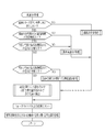
図15は、今回の操作時と前回の操作時も構図が略一致しているか否かを判断し、構図が略一致していると判断した場合に、前回のレリーズボタンの操作時と同じAF動作で合焦位置の検出を行うようにしたものである。この例では、高速処理AF処理が完了すると、例えば、前回の高速AF処理で選択されたAF動作と、そのAF動作で合焦位置を検出できたか否か、またレリーズボタン7の半押し時に測定された被写体輝度EV1がそれぞれシステム制御部11によってRAM11bに書き込まれて保持される。
FIG. 15 shows whether or not the composition is substantially the same during the current operation and the previous operation, and when it is determined that the composition is substantially the same, the same AF as during the previous release button operation is performed. The focus position is detected by the operation. In this example, when the high-speed processing AF processing is completed, for example, measurement is performed when the AF operation selected in the previous high-speed AF processing, the in-focus position has been detected by the AF operation, and when the
次にレリーズボタン7の半押し操作に応答して、高速AF処理が行われた場合には、システム制御部11は、RAM11bにアクセスし、まず前回のレリーズボタン7の半押し時の高速AF処理によって合焦位置を検出できたか否かを判断する。前回に合焦位置を検出している場合には、前回のレリーズボタン7が半押しに応答した合焦時、すなわちフォーカスレンズ15aが合焦位置とされた時点から今回の半押しとされるまでの経過時間が所定時間以内であるか、前回のレリーズボタン7の半押しに応答した静止画用AE処理で測定された被写体輝度EV1と今回のレリーズボタン7の半押しに応答した静止画用AE処理で測定された被写体輝度EV1との差が所定値以下であるかを調べ、構図のズレの判断を行う。
Next, when high-speed AF processing is performed in response to the half-pressing operation of the
経過時間が所定時間以内であり、かつ各被写体輝度EV1との差が所定値以下である場合には、構図が略一致していると判断して、RAM11bにアクセスして前回のAF動作を調べ、調べた前回のAF動作で合焦位置の検出を行う。なお、構図のズレを判断する際に用いられる所定時間と被写体輝度EV1との差は、実質的に構図のズレが発生していないといえる程度の小さな値に実験的、統計的に決定されている。また、経過時間の計時起点として合焦時ではなく、前回のレリーズボタン7の半押時としてもよい。
If the elapsed time is within a predetermined time and the difference from each subject brightness EV1 is equal to or less than the predetermined value, it is determined that the composition is substantially the same, and the
経過時間が所定時間以内でない場合や、被写体輝度の差が所定値以下でない場合には、構図が大きく変化したものと判断し、基本高速AF処理を行う。この基本高速AF処理は、図7や図10,図12,図13,図14等に示す手順と同様なAF動作であるが、他のパラメータに基づいて選択したAF動作で合焦位置を検出してもよい。 When the elapsed time is not within the predetermined time or when the difference in subject luminance is not less than the predetermined value, it is determined that the composition has changed greatly, and the basic high-speed AF process is performed. This basic high-speed AF process is an AF operation similar to the procedure shown in FIGS. 7, 10, 12, 13, 14, etc., but the in-focus position is detected by an AF operation selected based on other parameters. May be.
前回のレリーズボタン7の操作に応答して合焦位置を検出できていなかった場合には、図16に示す前回非合焦処理を行う。この前回非合焦処理では、システム制御部11によって、まず前回の合焦位置を検出できなかったAF処理から今回の半押しとされるまでの経過時間が所定時間以内であるか、前回と今回の各被写体輝度EV1との差が所定値以下であるかを調べ、構図のズレの判断を行う。
If the in-focus position has not been detected in response to the previous operation of the
前回非合焦処理において、経過時間が所定時間以内であり、かつ各被写体輝度EV1の差が所定値以下であって構図が略一致していると判断した場合には、前回のAF動作を調べ、これとは異なるAF動作を選択する。この例では、前回のAF動作が第1AF動作であった場合には、今回は第2AF動作を選択し、前回のAF動作が第2AF動作であった場合には、今回は第1AF動作を選択する。また、前回第3AF動作が選択されていた場合には、今回は第1AF動作を選択する。そして、この選択したAF動作で合焦位置の検出を行う。このように前回と異なるAF動作を選択することで、合焦位置を検出できる可能性を高めている。 In the previous out-of-focus process, if it is determined that the elapsed time is within a predetermined time and the difference between the subject brightness EV1 is equal to or smaller than the predetermined value and the composition is substantially the same, the previous AF operation is checked. A different AF operation is selected. In this example, when the previous AF operation is the first AF operation, the second AF operation is selected this time, and when the previous AF operation is the second AF operation, the first AF operation is selected this time. To do. If the third AF operation was previously selected, the first AF operation is selected this time. Then, the focus position is detected by the selected AF operation. In this way, by selecting an AF operation different from the previous time, the possibility that the in-focus position can be detected is increased.
なお、前回非合焦処理において、経過時間が所定時間以内でない場合や、被写体輝度の差が所定値以下でなく、構図が大きく変化したと判断された際には、基本高速AF処理を行う。もちろん、前回非合焦処理として、基本高速AF処理を行うように構成することもできる。 In the previous out-of-focus process, the basic high-speed AF process is performed when the elapsed time is not within a predetermined time or when it is determined that the difference in subject luminance is not less than the predetermined value and the composition has changed significantly. Of course, the basic high-speed AF process can be performed as the previous out-of-focus process.
図17は前回の合焦位置を記憶しておき、構図が略一致していると判断した場合に、前回の合焦位置付近についてのみ合焦検出を行って高速化を図る例を示すものである。この例では、経過時間が所定時間以内であり、かつ被写体輝度EV1の差が所定値以下である場合には、さらに前回の被写体輝度EV3と今回の被写体輝度EV3とを比較する。 FIG. 17 shows an example in which the previous in-focus position is stored, and when it is determined that the composition is substantially the same, the in-focus detection is performed only in the vicinity of the previous in-focus position to increase the speed. is there. In this example, when the elapsed time is within a predetermined time and the difference in the subject luminance EV1 is equal to or smaller than a predetermined value, the previous subject luminance EV3 and the current subject luminance EV3 are further compared.
上記比較において、前回の被写体輝度EV3と今回の被写体輝度EV3との差が、所定値以下であり、その差がほとんどない場合には、構図のズレがほとんどないものと判断し、RAM11bから前回の合焦位置と前回のAF動作を読み出す。そして、図18に示すように、前回の合焦位置の前後の適当な範囲(以下、特定合焦検出範囲という)、例えば前回の合焦位置とその前後の数ステップ分の特定合焦検出範囲についてだけ、合焦検出を行うようにする。
In the above comparison, if the difference between the previous subject brightness EV3 and the current subject brightness EV3 is less than or equal to a predetermined value and there is almost no difference, it is determined that there is almost no composition deviation, and the
また、上記のように特定合焦検出範囲について合焦位置の検出を行う場合には、前回のAF動作によるフォーカスレンズ15aの移動方向を判断し、その移動方向でフォーカスレンズ15aを動かす。したがって、前回のAF動作が、例えば第1AF動作または第3AF動作であれば、特定合焦検出範囲の区間を近距離側から遠距離側に向けてをフォーカスレンズ15aを移動させて合焦位置の検出を行い、前回のAF動作が第2AF動作であった場合には、特定合焦検出範囲の区間を遠距離側から近距離側に向けてをフォーカスレンズ15aを移動させて合焦位置の検出を行う。
Further, when the focus position is detected in the specific focus detection range as described above, the movement direction of the
このように、前回と今回の各被写体輝度EV3までを比較して、構図のズレがほとんどないことが確からしいときには、特定合焦検出範囲についてだけ合焦検出を行うようにし、合焦位置の検出をより高速化する。なお、各被写体輝度EV3の差が所定値よりも大きい場合には、前回のAF動作をRAM11bから読み出して、そのAF動作と同じAF動作で合焦位置を検出する。
In this way, comparing the previous and current subject brightness EV3, and when it is certain that there is almost no deviation in composition, focus detection is performed only for the specific focus detection range, and detection of the focus position is performed. Speed up. If the difference between the subject brightness EV3 is larger than a predetermined value, the previous AF operation is read from the
この例では、被写体輝度EV1だけでなく、被写体輝度EV3の差までをパラメータとして構図のズレを判断しているが、各被写体輝度EV3を比較せずに、例えばレリーズボタン7の半押しとされた前回からの経過時間、各被写体輝度EV1の差の許容量を小さくして構図のズレを判断して、構図のズレがほとんどないと判断した場合に特定合焦検出範囲についてだけを合焦位置の検出対象とするように制御してもよい。
In this example, not only the subject brightness EV1 but also the difference in the subject brightness EV3 is used as a parameter to determine the composition deviation. For example, the
図19は、前回非合焦処理の他の例を示すものである。この例における前回非合焦処理では、まず前回からの経過時間が所定時間以内であるか、前回の被写体輝度EV1と今回の被写体輝度EV1との差が所定値以下であるかを調べ、構図のズレの判断を行う。経過時間が所定時間以内でない場合や、被写体輝度の差が所定値以下でない場合には、構図のズレが大きいと判断し、基本高速AF処理を行う。 FIG. 19 shows another example of the previous out-of-focus process. In the previous out-of-focus processing in this example, first, it is checked whether the elapsed time from the previous time is within a predetermined time or whether the difference between the previous subject luminance EV1 and the current subject luminance EV1 is equal to or less than a predetermined value. Judge the deviation. If the elapsed time is not within the predetermined time or if the difference in subject brightness is not less than the predetermined value, it is determined that the composition is misaligned, and basic high-speed AF processing is performed.
一方、経過時間が所定時間以内であり、かつ被写体輝度との差が所定値以下であって構図のズレがあまりないと判断した場合には、前回のAF動作が第3AF動作であったか否かを調べる。前回のAF動作が第3AF動作であった場合には、今回のレリーズボタン7の操作に応答して測定された被写体輝度EV1,EV3を比較する。この比較で被写体輝度EV3が被写体輝度EV1よりも所定の閾値EVth以上で大きい場合(EV3−EV1≧EVth)には、第1AF動作を行い、そうでない場合(EV3−EV1<EVth)には、第2AF動作を行う。また、前回のAF動作が第3AF動作でなかった場合には、今回のレリーズボタン7の操作に応答して測定された被写体輝度EV1,EV3を比較し、同様にAF動作を行うが、被写体輝度EV3が被写体輝度EV1より小さく「EV3−EV1<0」となる場合には、第2AF動作を行う。
On the other hand, if it is determined that the elapsed time is within the predetermined time and the difference from the subject brightness is equal to or less than the predetermined value and the composition is not misaligned, it is determined whether or not the previous AF operation was the third AF operation. Investigate. When the previous AF operation is the third AF operation, the subject luminances EV1 and EV3 measured in response to the current operation of the
上記のようにAF動作を行うことにより、前回が第3AF動作で合焦位置を検出できなかった場合には、今回の被写体輝度EV1と被写体輝度EV3との比較によって通常は第3AF動作とする場合であっても、第2AF動作とし、全域すなわち最短レンズ位置と無限遠レンズ位置との間を対象に合焦位置の検出を行わせ、合焦位置を検出できる可能性を向上させている。 By performing the AF operation as described above, if the focus position could not be detected in the third AF operation last time, the third AF operation is usually set by comparing the current subject brightness EV1 and the subject brightness EV3. Even so, the second AF operation is performed, and the focus position is detected for the entire region, that is, between the shortest lens position and the infinity lens position, thereby improving the possibility of detecting the focus position.
図20,図21に示す例では、前回非合焦処理において、合焦位置の検出を行うことができなかった理由が低コントラストを原因とする場合には、AF補助光量を増大させて、AF処理を再度行うものである。図20に示すように、補助光照射部6には、光源としての2個のLED33を設けてあり、AF補助光を照射する場合には、駆動回路34はシステム制御部11の制御に基づいて1個または2個のLED33を点灯させる。AF補助光を照射する場合には、通常は1個のLED33だけ点灯させるが、後述するように低コントラストが原因で合焦位置を検出できなかったときには、2個のLED33を点灯させてAF補助光の光量を増大させる。
In the example shown in FIGS. 20 and 21, if the reason why the focus position could not be detected in the previous out-of-focus process is caused by low contrast, the AF auxiliary light amount is increased and AF is performed. The process is performed again. As shown in FIG. 20, the auxiliary
図21に示すように、システム制御部11は、前回非合焦処理では、まず前回からの経過時間が所定時間以内であるか、前回の被写体輝度EV1と今回の被写体輝度EV1との差が所定値以下であるかを調べ、構図のズレの判断を行う。経過時間が所定時間以内でない場合や、被写体輝度の差が所定値以下でない場合には、構図のズレが大きいと判断し、基本高速AF処理を行う。一方、構図のズレが小さいと判断した場合には、システム制御部11は、前回に合焦位置を検出できなかった原因が低コントラストであったか否かを判断する。低コントラストが原因でない場合には、例えば図示されるように前回とは異なるAF動作で合焦位置の検出を行う。
As shown in FIG. 21, in the previous in-focus processing, the
また、低コントラストが原因で合焦位置が検出できなかったと判断した場合には、システム制御部11により駆動回路34を介して2個のLED33がそれぞれ点灯され、被写体に向けて照射するAF補助光を前回よりも増大させる。そして、このAF補助光の照射下で再AF処理を行う。再AF処理としては、例えばフォーカスレンズ15aのレンズ位置に応じたAF動作を選択してAF処理を行うが、その他の例えば前回と異なるAF動作を用いたAF処理でもよい。このようにAF補助光の光量を増大させることにより、被写体のコントラストを増大させて合焦位置の検出の可能性を高くする。
If it is determined that the in-focus position cannot be detected due to low contrast, the
合焦位置が検出できなかった原因が低コントラストによるものであるか否かは、被写体像から所定レベル以上のコントラストが得られていたか否かで判断されるものであり、具体的にはAF評価値が所定値よりも小さい場合で合焦位置が検出できなかったときに、その原因が低コントラストによるものであると判断される。 Whether or not the in-focus position cannot be detected is due to low contrast, which is determined by whether or not a predetermined level or more of contrast has been obtained from the subject image. Specifically, AF evaluation is performed. When the value is smaller than the predetermined value and the focus position cannot be detected, it is determined that the cause is due to the low contrast.
図22は、前回のレリーズボタン7の半押しに応答して合焦位置が検出され、また構図のズレがほとんどないと判断した場合に、AF用AE処理を省略してAF処理を行うようにしたものである。この例では、各被写体輝度EV1の差と経過時間とから構図のズレがほとんどないと判断した場合に、AF用AE処理を行わずに、前回のAF用AE処理の結果に基づいた露出値EV3で高速AF処理を行う。
In FIG. 22, when the in-focus position is detected in response to the previous half-press of the
これにより、AF用AE処理を省略でき、その分だけAF処理の完了を早めることができる。なお、構図のズレの判断は、他の実施形態と同様に、前回からの経過時間が所定時間以内であるか、前回の被写体輝度EV1と今回の被写体輝度EV1の差に基づいて行うことができるが、できるだけ構図のズレ量が少ない場合に限ってAF用AE処理を省略することが好ましい。このため、構図のズレがないと判断する際に許容する前回の被写体輝度EV1と今回の被写体輝度との差は、他の実施形態等に用いたものよりも小さい差とするのがよい。 Thereby, the AF AE process can be omitted, and the completion of the AF process can be accelerated by that much. Note that the compositional deviation can be determined based on the difference between the previous subject brightness EV1 and the current subject brightness EV1 or whether the elapsed time from the previous time is within a predetermined time, as in the other embodiments. However, it is preferable to omit the AF AE process only when the composition deviation amount is as small as possible. For this reason, the difference between the previous subject brightness EV1 and the current subject brightness that is allowed when it is determined that there is no composition deviation is preferably smaller than that used in the other embodiments.
上記の構図のズレを判断する各実施形態では、経過時間と被写体輝度によって構図のズレを判断しているが、例えばフォーカスレンズの位置を用いて構図のズレを判断してもよい。また、上記各実施形態では、デジタルカメラを例にして説明しているが、撮影レンズのフォーカスレンズを移動させて合焦位置の検出を行う各種装置及びその制御方法に本発明を利用することができる。 In each of the embodiments for determining the compositional deviation, the compositional deviation is determined based on the elapsed time and the subject luminance. However, the compositional deviation may be determined using, for example, the position of the focus lens. In each of the above embodiments, the digital camera has been described as an example. However, the present invention can be applied to various apparatuses that detect the in-focus position by moving the focus lens of the photographing lens and the control method thereof. it can.
上記各実施形態では、操作部材としてのレリーズボタンが操作されない期間中に行うオートフォーカスと、レリーズボタンの操作に応答して行うオートフォーカスとは、いずれも撮影レンズを通して得られる被写体像のコントラストを評価するいわゆるTTLコントラスト検出方式を採用しているが、本発明は、操作部材が操作されない期間中に被写体に合焦するようにフォーカスレンズを移動させ、またレリーズボタンの操作に応答して合焦位置の検出を行うときにフォーカスレンズを移動させるのであれば、それに限定されるものではない。 In each of the above embodiments, the autofocus performed during a period when the release button as the operation member is not operated and the autofocus performed in response to the operation of the release button both evaluate the contrast of the subject image obtained through the photographing lens. In the present invention, the focus lens is moved so as to focus on the subject during a period when the operation member is not operated, and the focus position is responded to the operation of the release button. However, the present invention is not limited to this as long as the focus lens is moved when detecting the above.
例えば、撮影レンズからの被写体光をセパレータレンズで分離して2つの像を生成し、それら像間隔に基づいてピントのズレ量を検出するTTL位相差検出方式を用いてもよく、撮影レンズを通さずに外部AFセンサを用いた位相差検出方式を採用してもよい。外部AFセンサを用いた場合には、外部AFセンサの検出結果に基づいて、被写体に合焦するように、所定の間隔あるいは連続的にフォーカスレンズを移動させる。 For example, a TTL phase difference detection method may be used in which subject light from a photographing lens is separated by a separator lens to generate two images, and the amount of focus deviation is detected based on the image interval. Alternatively, a phase difference detection method using an external AF sensor may be employed. When the external AF sensor is used, the focus lens is moved at a predetermined interval or continuously so as to focus on the subject based on the detection result of the external AF sensor.
また、操作部材としてのレリーズボタンが操作されない期間中に行うオートフォーカスと、レリーズボタンの操作に応答して行うオートフォーカスとが異なる方式であってもよい。例えば、レリーズボタンが操作されないときには、外部AFセンサの検出結果に基づいて、被写体に合焦するように所定の間隔あるいは連続的にフォーカスレンズを移動させ、レリーズボタンの操作に応答してTTLコントラスト検出方式で合焦位置を検出するようにしてもよい。 Further, the auto focus performed during a period when the release button as the operation member is not operated may be different from the auto focus performed in response to the operation of the release button. For example, when the release button is not operated, the focus lens is moved at a predetermined interval or continuously so as to focus on the subject based on the detection result of the external AF sensor, and the TTL contrast is detected in response to the operation of the release button. The focus position may be detected by a method.
さらに、一眼レフタイプのデジタルカメラなどでは、レリーズボタンの操作されない期間中は特にピント合わせを行わないものもあるが、このようなカメラであっても、例えばファインダに配置された接眼センサにより、撮影者がファインダを覗いたことを検知した瞬間から所定の間隔あるいは連続的にピント合わせを開始するのであれば、本発明を適用することができる。 Furthermore, some single-lens reflex type digital cameras do not focus particularly during periods when the release button is not operated. Even with such cameras, for example, an image is taken by an eye sensor disposed in the viewfinder. The present invention can be applied as long as focusing is started at a predetermined interval or continuously from the moment when a person looks into the viewfinder.
2 デジタルカメラ
4 撮影レンズ
6 補助光照射部
6a 照射窓
11 システム制御部
13 イメージセンサ
15 フォーカス機構
15a フォーカスレンズ
15b レンズ位置検出手段
24 AF検出部
25 AE検出部
DESCRIPTION OF
Claims (19)
前記フォーカスレンズのレンズ位置を検出するレンズ位置検出手段と、
撮影を指示するための操作部材と、
操作部材の操作されない期間中に、所定の間隔でフォーカスレンズを移動させて被写体に合焦させるように制御する第1の合焦制御手段と、
前記操作部材の操作に応答して、その操作時点で前記レンズ位置検出手段から取得したレンズ位置に応じて前記フォーカスレンズの移動開始位置と移動方向とを決定し移動させて、前記フォーカスレンズの移動ごとに前記撮影レンズを通して得られる光学像を評価し、被写体に合焦するフォーカスレンズの合焦位置を検出する第2の合焦制御手段とを備えたことを特徴とする撮影装置。 A shooting lens whose focusing distance is adjusted by moving the focus lens;
Lens position detecting means for detecting a lens position of the focus lens;
An operation member for instructing photographing;
A first focus control means for controlling to move the focus lens at a predetermined interval to focus on the subject during a period when the operation member is not operated;
In response to the operation of the operation member, the focus lens movement start position and the movement direction are determined and moved according to the lens position acquired from the lens position detection means at the time of the operation, and the focus lens is moved. A photographing apparatus comprising: a second focusing control unit that evaluates an optical image obtained through the photographing lens and detects a focusing position of a focusing lens that focuses on a subject.
前記フォーカスレンズのレンズ位置を検出するレンズ位置検出手段と、
撮影を指示するための操作部材と、
前記操作部材の操作に応答して合焦位置を検出する際に、照明光を被写体に向けて照射する照明光照射手段と、
前記操作部材の操作に応答して照明光を照射していない状態と照射した状態との各被写体輝度を検出する輝度検出手段と、
操作部材の操作されない期間中に、所定の間隔でフォーカスレンズを移動させて被写体に合焦させるように制御する第1の合焦制御手段と、
前記操作部材の操作に応答して、その操作時点で前記レンズ位置検出手段から取得したレンズ位置と、前記輝度検出手段から取得した照明光を照射していない状態と照射した状態との各被写体輝度の大小関係とに応じて、前記フォーカスレンズの移動開始位置と移動方向とを決定し移動させて、前記フォーカスレンズの移動ごとに前記撮影レンズを通して得られる光学像を評価し、被写体に合焦するフォーカスレンズの合焦位置を検出する第2の合焦制御手段とを備えたことを特徴とする撮影装置。 A shooting lens whose focusing distance is adjusted by moving the focus lens;
Lens position detecting means for detecting a lens position of the focus lens;
An operation member for instructing photographing;
Illumination light irradiating means for irradiating illumination light toward a subject when detecting a focus position in response to an operation of the operation member;
Brightness detection means for detecting each subject brightness in a state where the illumination light is not irradiated and an irradiated state in response to the operation of the operation member;
A first focus control means for controlling to move the focus lens at a predetermined interval to focus on the subject during a period when the operation member is not operated;
In response to the operation of the operation member, the subject position of the lens position acquired from the lens position detection means at the time of the operation, and the illumination light acquired from the brightness detection means and the irradiated state The movement start position and the movement direction of the focus lens are determined and moved in accordance with the magnitude relationship of the focus lens, and an optical image obtained through the photographing lens is evaluated for each movement of the focus lens to focus on the subject. An imaging apparatus comprising: a second focus control unit that detects a focus position of the focus lens.
増大していない場合で、前記レンズ位置検出手段から取得したレンズ位置が遠距離側の移動端よりも近距離側の移動端に近いときには、近距離側の移動端を移動開始位置として遠距離側に向けて前記フォーカスレンズを移動させ、取得したレンズ位置が近距離側の移動端よりも遠距離側の移動端に近いときには、遠距離側の移動端を移動開始位置として近距離側に向けて前記フォーカスレンズ移動させることを特徴とする請求項4記載の撮影装置。 When the subject brightness in the state where the illumination light is irradiated is increased with respect to the subject brightness in the state where the illumination light is not irradiated, the second focus control unit uses the short-distance side moving end as a movement start position to make a long distance Move the focus lens toward the side,
If the lens position acquired from the lens position detecting means is closer to the moving end on the near side than the moving end on the far side, and the moving end on the near side is set as the movement start position, When the acquired lens position is closer to the moving end on the far side than the moving end on the near side, the moving end on the far side is set as the movement start position toward the near side. The photographing apparatus according to claim 4, wherein the focus lens is moved.
今回の操作時と前回の操作時の前記イメージセンサによって撮影される構図が略一致しているか否かを判断する判断手段とを備え、
前記第2の合焦制御手段は、前記判断手段によって構図が略一致していると判断されたときには、前記動作記憶手段に保持されている前回の前記操作部材の操作に応答して決定された移動開始位置と移動方向とを用いてフォーカスレンズを移動させて合焦位置の検出を行うことを特徴とする請求項1ないし6のいずれか1項に記載の撮影装置。 Operation storage means for storing and holding the movement start position and movement direction of the focus lens determined in response to the operation of the operation member;
Determination means for determining whether or not the composition photographed by the image sensor at the time of the current operation and the previous operation is substantially the same,
The second focus control unit is determined in response to the previous operation of the operation member held in the operation storage unit when the determination unit determines that the composition is substantially the same. The imaging apparatus according to claim 1, wherein the focus position is detected by moving the focus lens using the movement start position and the movement direction.
前回の前記操作部材の操作に応答して決定された前記フォーカスレンズの移動開始位置と移動方向とを記憶して保持する動作記憶手段と、
前回の操作部材の操作に応答して測定された被写体輝度と今回の操作部材の操作に応答して測定された被写体輝度との輝度差が第1の閾値以下であり、前回の操作部材の操作に応答した合焦時から今回の操作部材の操作までの経過時間が第2の閾値以下である場合に、構図が略一致していると判断する判断手段とを備え、
前記第2の合焦制御手段は、前記判断手段によって構図が略一致していると判断されたときには、前記動作記憶手段に保持されている前回の前記操作部材の操作に応答して決定された移動開始位置と移動方向とを用いてフォーカスレンズを移動させて合焦位置の検出を行うことを特徴とする請求項3ないし6のいずれか1項に記載の撮影装置。 Brightness storage means for storing subject brightness detected by the brightness detection means in response to an operation of the operation member;
Operation storage means for storing and holding the movement start position and movement direction of the focus lens determined in response to the previous operation of the operation member;
The luminance difference between the subject brightness measured in response to the previous operation of the operation member and the subject brightness measured in response to the operation of the current operation member is equal to or less than the first threshold, and the previous operation member operation Determining means for determining that the composition is substantially the same when the elapsed time from the time of focusing in response to the operation of the current operation member is equal to or less than the second threshold value,
The second focus control unit is determined in response to the previous operation of the operation member held in the operation storage unit when the determination unit determines that the composition is substantially the same. The photographing apparatus according to claim 3, wherein the focus position is detected by moving the focus lens using the movement start position and the movement direction.
前記輝度検出手段は、操作部材の操作に応答して照明光を照射する場合で、前記判断手段によって構図が略一致していると判断され前回の操作部材の操作に応答して照明光の照射下で合焦位置が検出されているときには、照明光の照射した状態での輝度の検出を行わず、前記露出制御手段は、前記輝度検出手段によって照明光の照射した状態での輝度の検出を行わないときには、前回の操作部材の操作に応答して照明光の照射下で前記輝度検出手段によって検出された被写体輝度に基づいた露出値となるように制御することを特徴とする請求項8に記載の撮影装置。 Exposure control means is provided for controlling the exposure value based on the subject brightness detected by the brightness detection means when the illumination light is irradiated to detect the in-focus position. ,
The luminance detecting means irradiates illumination light in response to operation of the operation member, and the determination means determines that the composition is substantially the same, and irradiates illumination light in response to the previous operation of the operation member. When the in-focus position is detected below, the exposure control means does not detect the brightness in the illumination light irradiation state, and the exposure control means detects the brightness in the illumination light irradiation state by the brightness detection means. 9. When not performed, control is performed so that the exposure value is based on the subject brightness detected by the brightness detecting means under illumination light irradiation in response to the previous operation of the operating member. The imaging device described.
前記輝度検出手段は、前記操作部材の操作に応答して照明光を照射していない状態と照射した状態との各被写体輝度を検出し、
前記判断手段は、構図が略一致していると判断したときには、さらに前回の操作部材の操作に応答して照明光を照射した状態で検出された被写体輝度と今回の操作部材の操作に応答して検出された被写体輝度との輝度差が第3の閾値以下であるか否かを判断し、前記第2の合焦制御手段は、前記判断手段によって前記各被写体輝度の差が第3の閾値以下であると判断されたときには、フォーカスレンズの移動可能な範囲のうち、前記位置記憶手段に保持された前回の操作部材の操作に応答して検出された合焦位置を挟む部分的な範囲でフォーカスレンズを移動させて合焦位置を検出させることを特徴とする請求項8記載の撮影装置。 A position storage means for storing and holding a focus position detected in response to an operation of the operation member;
The brightness detecting means detects each subject brightness in a state where the illumination light is not irradiated and an irradiated state in response to the operation of the operation member,
When it is determined that the composition is substantially the same, the determining means further responds to the subject brightness detected in the state in which the illumination light is irradiated in response to the previous operation of the operation member and the operation of the current operation member. Determining whether the difference in luminance from the detected subject luminance is equal to or smaller than a third threshold value, and the second focus control unit determines whether the difference in the subject luminance is a third threshold value by the determining unit. When it is determined that it is below, it is a partial range that sandwiches the in-focus position detected in response to the previous operation of the operation member held in the position storage means within the movable range of the focus lens. The photographing apparatus according to claim 8, wherein the focus lens is moved to detect a focus position.
撮影を指示する操作部材の操作に応答して、操作部材の操作されない期間中に所定の間隔で合焦位置の検出を行って検出した合焦位置となるようにレンズ位置が調節されているフォーカスレンズのレンズ位置を取得し、取得したレンズ位置に応じて前記フォーカスレンズの移動開始位置と移動方向とを決定し移動させて合焦位置の検出を行わせることを特徴とする撮影レンズの合焦制御方法。 In the focus control method of the photographic lens for detecting the focus position of the focus lens that focuses on the subject by moving the focus lens constituting the photographic lens,
In response to the operation of the operation member instructing shooting, the lens position is adjusted so that the focus position is detected by detecting the focus position at a predetermined interval during a period when the operation member is not operated. Focusing of a photographic lens characterized by acquiring a lens position of a lens, determining a movement start position and a movement direction of the focus lens according to the acquired lens position, and moving the focus lens to detect a focus position Control method.
撮影を指示するための前記操作部材の操作に応答して、照明光を照射していない状態と照射した状態との各被写体輝度を検出するとともに、操作部材の操作されない期間中に所定の間隔で合焦位置の検出を行って検出した合焦位置となるようにレンズ位置が調節されているフォーカスレンズのレンズ位置を取得し、取得したレンズ位置と検出した各被写体輝度の大小関係とに応じて、前記フォーカスレンズの移動開始位置と移動方向とを決定し移動させて、合焦位置の検出を行わせることを特徴とする撮影レンズの合焦制御方法。 In the focus control method of the photographic lens for detecting the focus position of the focus lens that focuses on the subject by moving the focus lens constituting the photographic lens,
In response to the operation of the operation member for instructing shooting, the luminance of each subject in the state where the illumination light is not irradiated and the state where the illumination light is irradiated is detected, and at a predetermined interval during a period when the operation member is not operated. The lens position of the focus lens whose lens position is adjusted so that it becomes the detected focus position is obtained by detecting the focus position, and according to the magnitude relationship between the acquired lens position and each detected subject brightness A focus control method for a photographic lens, wherein a focus start position is detected by determining and moving a movement start position and a movement direction of the focus lens.
Priority Applications (2)
| Application Number | Priority Date | Filing Date | Title |
|---|---|---|---|
| JP2007084693A JP2008242226A (en) | 2007-03-28 | 2007-03-28 | Imaging apparatus and focusing control method for imaging lens |
| US12/058,395 US7953318B2 (en) | 2007-03-28 | 2008-03-28 | Imaging apparatus and focusing method |
Applications Claiming Priority (1)
| Application Number | Priority Date | Filing Date | Title |
|---|---|---|---|
| JP2007084693A JP2008242226A (en) | 2007-03-28 | 2007-03-28 | Imaging apparatus and focusing control method for imaging lens |
Publications (1)
| Publication Number | Publication Date |
|---|---|
| JP2008242226A true JP2008242226A (en) | 2008-10-09 |
Family
ID=39794549
Family Applications (1)
| Application Number | Title | Priority Date | Filing Date |
|---|---|---|---|
| JP2007084693A Abandoned JP2008242226A (en) | 2007-03-28 | 2007-03-28 | Imaging apparatus and focusing control method for imaging lens |
Country Status (2)
| Country | Link |
|---|---|
| US (1) | US7953318B2 (en) |
| JP (1) | JP2008242226A (en) |
Cited By (6)
| Publication number | Priority date | Publication date | Assignee | Title |
|---|---|---|---|---|
| JP2010156728A (en) * | 2008-12-26 | 2010-07-15 | Nikon Corp | Autofocus device and camera equipped with the autofocus device |
| JP2010268388A (en) * | 2009-05-18 | 2010-11-25 | Olympus Imaging Corp | Imaging apparatus |
| KR20110061918A (en) * | 2009-12-02 | 2011-06-10 | 삼성전자주식회사 | Autofocusing method for determining the moving direction of the focus lens, recording medium recording the method, autofocusing apparatus |
| JP2014002409A (en) * | 2008-10-30 | 2014-01-09 | Panasonic Corp | Imaging apparatus |
| JP2015028591A (en) * | 2013-06-24 | 2015-02-12 | キヤノン株式会社 | Imaging device, method for controlling imaging device, program, and storage medium |
| CN104702839A (en) * | 2013-12-03 | 2015-06-10 | 罗伯特·博世有限公司 | Method for automatically focusing a camera |
Families Citing this family (15)
| Publication number | Priority date | Publication date | Assignee | Title |
|---|---|---|---|---|
| JP4558830B2 (en) * | 2006-08-22 | 2010-10-06 | パナソニック株式会社 | Imaging device |
| JP4544282B2 (en) * | 2007-09-14 | 2010-09-15 | ソニー株式会社 | Data processing apparatus, data processing method, and program |
| JP5564996B2 (en) * | 2009-07-23 | 2014-08-06 | 株式会社リコー | Imaging apparatus and imaging method |
| JP5478213B2 (en) * | 2009-11-20 | 2014-04-23 | オリンパスイメージング株式会社 | camera |
| JP2011138103A (en) * | 2009-12-02 | 2011-07-14 | Ricoh Co Ltd | Imaging apparatus and method |
| JP5523143B2 (en) * | 2010-02-25 | 2014-06-18 | オリンパスイメージング株式会社 | Imaging apparatus and automatic focusing method |
| US8760563B2 (en) | 2010-10-19 | 2014-06-24 | Hand Held Products, Inc. | Autofocusing optical imaging device |
| US8692927B2 (en) | 2011-01-19 | 2014-04-08 | Hand Held Products, Inc. | Imaging terminal having focus control |
| JP5941630B2 (en) * | 2011-07-14 | 2016-06-29 | オリンパス株式会社 | camera |
| US8779614B2 (en) * | 2011-11-04 | 2014-07-15 | Schlumberger Technology Corporation | Power generation at a subsea location |
| US9392158B2 (en) | 2012-10-04 | 2016-07-12 | Nvidia Corporation | Method and system for intelligent dynamic autofocus search |
| US9621780B2 (en) * | 2012-10-04 | 2017-04-11 | Nvidia Corporation | Method and system of curve fitting for common focus measures |
| JP6145822B2 (en) * | 2012-10-12 | 2017-06-14 | パナソニックIpマネジメント株式会社 | Imaging device |
| JP6474693B2 (en) * | 2015-06-19 | 2019-02-27 | オリンパス株式会社 | Focus detection apparatus, focus detection method, and recording medium |
| KR20180031288A (en) * | 2016-09-19 | 2018-03-28 | 삼성전자주식회사 | Image sensor and imaging device including the same |
Citations (5)
| Publication number | Priority date | Publication date | Assignee | Title |
|---|---|---|---|---|
| JP2001166200A (en) * | 1999-12-08 | 2001-06-22 | Olympus Optical Co Ltd | Electronic camera provided with auto-fucusing function |
| JP2003215435A (en) * | 2002-01-21 | 2003-07-30 | Konica Corp | Imaging device |
| JP2003315670A (en) * | 2002-04-26 | 2003-11-06 | Nikon Gijutsu Kobo:Kk | Camera |
| JP2006126611A (en) * | 2004-10-29 | 2006-05-18 | Fuji Photo Film Co Ltd | Imaging device |
| JP2007057974A (en) * | 2005-08-25 | 2007-03-08 | Fujifilm Holdings Corp | Imaging device |
Family Cites Families (11)
| Publication number | Priority date | Publication date | Assignee | Title |
|---|---|---|---|---|
| JP3799077B2 (en) | 1994-12-06 | 2006-07-19 | キヤノン株式会社 | Imaging apparatus and imaging method |
| US6670989B2 (en) * | 1997-05-16 | 2003-12-30 | Canon Kabushiki Kaisha | Optical system driving control device and camera using the same |
| JP2002341230A (en) | 2001-05-14 | 2002-11-27 | Konica Corp | Camera and af auxiliary light control method |
| JP3997393B2 (en) * | 2001-06-29 | 2007-10-24 | フジノン株式会社 | camera |
| JP4090276B2 (en) * | 2002-05-28 | 2008-05-28 | 富士フイルム株式会社 | Digital camera |
| JP2004294103A (en) * | 2003-03-25 | 2004-10-21 | Fuji Photo Optical Co Ltd | Range finder |
| JP3730970B2 (en) * | 2003-03-27 | 2006-01-05 | フジノン株式会社 | camera |
| JP2005086499A (en) * | 2003-09-09 | 2005-03-31 | Minolta Co Ltd | Imaging device |
| JP2006003212A (en) * | 2004-06-17 | 2006-01-05 | Konica Minolta Sensing Inc | Phase measurement system |
| EP1679546B1 (en) * | 2005-01-07 | 2014-12-24 | Canon Kabushiki Kaisha | Focus control method and focus control apparatus |
| US7725018B2 (en) * | 2006-08-01 | 2010-05-25 | Canon Kabushiki Kaisha | Focus control apparatus, image sensing apparatus and focus control method |
-
2007
- 2007-03-28 JP JP2007084693A patent/JP2008242226A/en not_active Abandoned
-
2008
- 2008-03-28 US US12/058,395 patent/US7953318B2/en not_active Expired - Fee Related
Patent Citations (5)
| Publication number | Priority date | Publication date | Assignee | Title |
|---|---|---|---|---|
| JP2001166200A (en) * | 1999-12-08 | 2001-06-22 | Olympus Optical Co Ltd | Electronic camera provided with auto-fucusing function |
| JP2003215435A (en) * | 2002-01-21 | 2003-07-30 | Konica Corp | Imaging device |
| JP2003315670A (en) * | 2002-04-26 | 2003-11-06 | Nikon Gijutsu Kobo:Kk | Camera |
| JP2006126611A (en) * | 2004-10-29 | 2006-05-18 | Fuji Photo Film Co Ltd | Imaging device |
| JP2007057974A (en) * | 2005-08-25 | 2007-03-08 | Fujifilm Holdings Corp | Imaging device |
Cited By (8)
| Publication number | Priority date | Publication date | Assignee | Title |
|---|---|---|---|---|
| JP2014002409A (en) * | 2008-10-30 | 2014-01-09 | Panasonic Corp | Imaging apparatus |
| US9077892B2 (en) | 2008-10-30 | 2015-07-07 | Panasonic Intellectual Property Management Co., Ltd. | Imaging apparatus using different focus lens driving methods between when zoom magnification is changed and when not changed |
| JP2010156728A (en) * | 2008-12-26 | 2010-07-15 | Nikon Corp | Autofocus device and camera equipped with the autofocus device |
| JP2010268388A (en) * | 2009-05-18 | 2010-11-25 | Olympus Imaging Corp | Imaging apparatus |
| KR20110061918A (en) * | 2009-12-02 | 2011-06-10 | 삼성전자주식회사 | Autofocusing method for determining the moving direction of the focus lens, recording medium recording the method, autofocusing apparatus |
| KR101594000B1 (en) | 2009-12-02 | 2016-02-26 | 삼성전자주식회사 | Auto focusing method medium for recording the method auto focusing apparatus |
| JP2015028591A (en) * | 2013-06-24 | 2015-02-12 | キヤノン株式会社 | Imaging device, method for controlling imaging device, program, and storage medium |
| CN104702839A (en) * | 2013-12-03 | 2015-06-10 | 罗伯特·博世有限公司 | Method for automatically focusing a camera |
Also Published As
| Publication number | Publication date |
|---|---|
| US20080240700A1 (en) | 2008-10-02 |
| US7953318B2 (en) | 2011-05-31 |
Similar Documents
| Publication | Publication Date | Title |
|---|---|---|
| JP2008242226A (en) | Imaging apparatus and focusing control method for imaging lens | |
| JP5942444B2 (en) | Digital camera | |
| JP3992992B2 (en) | Subject image acquisition device | |
| TWI423664B (en) | Imaging apparatus and exposure control method | |
| CN1928692B (en) | Camera apparatus having a plurality of image pickup elements | |
| CN103119511B (en) | Display control method and device for viewfinder device | |
| US8559808B2 (en) | Imaging apparatus | |
| JP4815330B2 (en) | Imaging apparatus and control method thereof | |
| JP5054635B2 (en) | Imaging device | |
| JP2008164731A (en) | Imaging apparatus and control method thereof | |
| JP2008197144A (en) | Imaging apparatus, imaging lens focusing control method and control apparatus | |
| JP5333888B2 (en) | Imaging apparatus and program thereof | |
| JP4170194B2 (en) | Imaging device | |
| JP2007233113A (en) | Ranging apparatus and method | |
| JP2006243372A (en) | Camera | |
| JP4813439B2 (en) | Imaging apparatus and control method thereof | |
| JP2010074743A (en) | Imaging device | |
| JP4496051B2 (en) | Imaging device | |
| JP2010147612A (en) | Camera and camera system | |
| JP2009109792A (en) | Autofocus device and camera using the same | |
| JP2005024858A (en) | Digital single-lens reflex camera | |
| JP4396309B2 (en) | Imaging apparatus and imaging method | |
| KR100965322B1 (en) | Exposure Control Device and Method of Digital Camera | |
| JP2008257083A (en) | Electronic camera | |
| JP2005024857A (en) | Digital single-lens reflex camera |
Legal Events
| Date | Code | Title | Description |
|---|---|---|---|
| A621 | Written request for application examination |
Free format text: JAPANESE INTERMEDIATE CODE: A621 Effective date: 20090910 |
|
| A977 | Report on retrieval |
Free format text: JAPANESE INTERMEDIATE CODE: A971007 Effective date: 20110329 |
|
| A131 | Notification of reasons for refusal |
Free format text: JAPANESE INTERMEDIATE CODE: A131 Effective date: 20110406 |
|
| A521 | Request for written amendment filed |
Free format text: JAPANESE INTERMEDIATE CODE: A523 Effective date: 20110603 |
|
| A762 | Written abandonment of application |
Free format text: JAPANESE INTERMEDIATE CODE: A762 Effective date: 20110607 |