JP2014059405A - Imaging apparatus, focusing position detecting method, and focusing position detecting program - Google Patents
Imaging apparatus, focusing position detecting method, and focusing position detecting program Download PDFInfo
- Publication number
- JP2014059405A JP2014059405A JP2012203568A JP2012203568A JP2014059405A JP 2014059405 A JP2014059405 A JP 2014059405A JP 2012203568 A JP2012203568 A JP 2012203568A JP 2012203568 A JP2012203568 A JP 2012203568A JP 2014059405 A JP2014059405 A JP 2014059405A
- Authority
- JP
- Japan
- Prior art keywords
- evaluation value
- lens
- focus
- start position
- acquired
- Prior art date
- Legal status (The legal status is an assumption and is not a legal conclusion. Google has not performed a legal analysis and makes no representation as to the accuracy of the status listed.)
- Pending
Links
Images




Landscapes
- Focusing (AREA)
- Automatic Focus Adjustment (AREA)
- Studio Devices (AREA)
Abstract
【課題】撮影の状況に応じてAF動作をさらに高速化し、操作の応答性を高めることができる撮像装置、合焦位置検出方法および合焦位置検出プログラムを提供する。
【解決手段】フォーカスレンズを第1の方向に移動させながら画像データからAF評価値を取得し、取得したAF評価値に基づいてAF開始位置を決定するAF開始位置決定部と、決定されたAF開始位置からフォーカスレンズを第1の方向とは逆方向である第2の方向に移動させながら画像データからAF評価値を取得し、取得したAF評価値に基づいて合焦位置を検出するAF処理部とを備え、AF開始位置決定部は、フォーカスレンズが目標位置に移動するまでの間にAF評価値のピークが検出され、かつ、所定条件を満たす場合に、AF評価値のピークが検出されたフォーカスレンズの位置を合焦位置とみなして、AF処理部による合焦位置の検出をキャンセルさせる。
【選択図】図10An imaging apparatus, an in-focus position detection method, and an in-focus position detection program capable of further speeding up an AF operation in accordance with shooting conditions and improving operation responsiveness are provided.
An AF start position determination unit that acquires an AF evaluation value from image data while moving a focus lens in a first direction, and determines an AF start position based on the acquired AF evaluation value; AF processing for acquiring an AF evaluation value from image data while moving the focus lens from the start position in a second direction opposite to the first direction, and detecting a focus position based on the acquired AF evaluation value The AF start position determination unit detects the peak of the AF evaluation value until the focus lens moves to the target position, and detects the peak of the AF evaluation value when a predetermined condition is satisfied. The position of the focus lens is regarded as the focus position, and the detection of the focus position by the AF processing unit is cancelled.
[Selection] Figure 10
Description
本発明は、被写体に対して自動的に焦点を合わせるオートフォーカス機能を備える撮像装置、合焦位置検出方法および合焦位置検出プログラムに関する。 The present invention relates to an imaging apparatus having an autofocus function for automatically focusing on a subject, a focus position detection method, and a focus position detection program.
デジタルスチルカメラ等の撮像装置は、被写体に対して自動的に焦点を合わせるオートフォーカス(以下、「AF」という。)機能を備えるものが一般的である。AF動作の制御方法としては、山登りAF制御が広く知られている(例えば、特許文献1参照)。この山登りAF制御では、撮像部から出力される画像データから近接画素の輝度差の積分値を求めて、この輝度差の積分値を、合焦度合いを示すAF評価値とする。合焦状態にあるときは被写体の輪郭部分がはっきりしており、近接画素間の輝度差が大きくなるのでAF評価値が大きくなる。一方、非合焦状態のときは被写体の輪郭部分がぼやけて画素間の輝度差は小さくなるので、AF評価値が小さくなる。AF動作の実行時は、レンズを移動させながら、所定のタイミングないしは一定の時間間隔でそのときのレンズ位置で撮像部から出力される画像データからAF評価値を取得し、AF評価値が最も大きくなったところ、すなわちピーク位置を合焦位置として検出し、合焦位置にレンズを移動させて停止させることで、被写体に対して自動的に焦点を合わせる。 An imaging apparatus such as a digital still camera generally has an autofocus (hereinafter referred to as “AF”) function that automatically focuses on a subject. As a control method of the AF operation, hill-climbing AF control is widely known (for example, see Patent Document 1). In this hill-climbing AF control, an integrated value of the luminance difference of the neighboring pixels is obtained from the image data output from the imaging unit, and this integrated value of the luminance difference is used as an AF evaluation value indicating the degree of focus. When the subject is in focus, the outline of the subject is clear and the brightness difference between adjacent pixels increases, so the AF evaluation value increases. On the other hand, in the out-of-focus state, the contour portion of the subject is blurred and the luminance difference between pixels becomes small, so the AF evaluation value becomes small. When performing the AF operation, the AF evaluation value is acquired from the image data output from the imaging unit at a predetermined timing or at a fixed time interval while moving the lens, and the AF evaluation value is the largest. In other words, the peak position is detected as the in-focus position, the lens is moved to the in-focus position and stopped, and the subject is automatically focused.
従来の一般的な山登りAF制御方法は、一旦、レンズの移動範囲全体にわたりレンズを移動させてその間に最大のAF評価値が得られるレンズ位置を特定し、この特定した位置までレンズを移動させるようになっている。より具体的には、例えば、合焦位置を検出するためにレンズの移動を開始させる位置(以下、「AF開始位置」という。)をレンズの駆動範囲の中央位置に設定してまずこのAF開始位置までレンズを移動させ、このAF開始位置から一定の向き、例えば最近接合焦位置の方に向かってレンズを移動させた後、無限遠合焦位置の方に向かってレンズを反転移動させ、この間に最大のAF評価値が得られる合焦位置を検出するようになっている。このため、AF動作に多くの時間を要し、シャッタチャンスを逃すことがあった。 In the conventional general hill-climbing AF control method, the lens is temporarily moved over the entire moving range of the lens, and the lens position at which the maximum AF evaluation value is obtained during that time is specified, and the lens is moved to this specified position. It has become. More specifically, for example, a position (hereinafter referred to as “AF start position”) at which the movement of the lens is started in order to detect the in-focus position is set to the center position of the lens driving range, and this AF start is started. Move the lens to the position, move the lens from this AF start position to a certain direction, for example, toward the closest focusing position, then reversely move the lens toward the infinite focusing position, The focus position where the maximum AF evaluation value is obtained is detected. For this reason, the AF operation takes a long time, and a photo opportunity may be missed.
そこで、AF動作を行う場合に、仮決めされたAF開始位置にレンズを移動させる間もAF評価値を取得して、取得したAF評価値に基づいて実際に合焦位置を検出するためのAF開始位置を決定し、このAF開始位置からレンズを反転移動させながらAF評価値を取得して合焦位置を検出することで、AF動作の高速化を図る技術が提案されている(例えば、特許文献2参照)。 Therefore, when performing an AF operation, an AF evaluation value is acquired even while the lens is moved to a temporarily determined AF start position, and an AF for actually detecting the in-focus position based on the acquired AF evaluation value There has been proposed a technique for speeding up the AF operation by determining the start position, acquiring the AF evaluation value while reversing the lens from the AF start position, and detecting the focus position (for example, patents). Reference 2).
特許文献2に開示される技術を用いることによって、特にレンズの駆動範囲が広い撮像装置におけるAF動作を高速化しながら、被写体に対して精度よく焦点を合わせることができる。しかし、動きのある被写体をすぐに撮影したいような状況では、合焦位置の精度よりも操作の応答性を優先させたい場合もある。つまり、撮影者が撮影したい被写体をみつけてから、撮像装置の電源をONして被写体を撮影する一連の動作を迅速に行えるようにするために、AF動作をさらに高速化することが望まれる。また、AF動作中に撮影者が意図的にレリーズスイッチを押し切る場合もあり、このような操作に対しても高い応答性が求められる。
By using the technique disclosed in
本発明は、上記に鑑みてなされたものであって、撮影の状況に応じてAF動作をさらに高速化し、操作の応答性を高めることができる撮像装置、合焦位置検出方法および合焦位置検出プログラムを提供することを目的としている。 The present invention has been made in view of the above, and an imaging apparatus, a focus position detection method, and a focus position detection that can further increase the speed of an AF operation and improve the responsiveness of an operation according to a shooting situation. The purpose is to provide a program.
上述した課題を解決し、目的を達成するために、本発明に係る撮像装置は、レンズと、前記レンズを用いて撮像した被写体像を画像データとして出力する撮像部と、前記レンズを第1の方向に移動させながら前記画像データからAF評価値を取得し、取得した前記AF評価値に基づいてAF開始位置を決定するAF開始位置決定部と、前記レンズを前記AF開始位置から前記第1の方向とは逆方向である第2の方向に移動させながら前記画像データから前記AF評価値を取得し、取得した前記AF評価値に基づいて合焦位置を検出するAF処理部と、を備え、前記AF開始位置決定部は、前記レンズが所定位置に移動するまでの間に前記AF評価値のピークが検出され、かつ、所定条件を満たす場合に、前記AF評価値のピークが検出された前記レンズの位置を前記合焦位置とみなして、前記AF処理部による前記合焦位置の検出をキャンセルさせることを特徴とする。 In order to solve the above-described problems and achieve the object, an imaging apparatus according to the present invention includes a lens, an imaging unit that outputs a subject image captured using the lens as image data, and the lens as a first. An AF evaluation value is acquired from the image data while being moved in the direction, an AF start position determination unit that determines an AF start position based on the acquired AF evaluation value, and the lens from the AF start position to the first An AF processing unit that acquires the AF evaluation value from the image data while moving in a second direction that is opposite to the direction, and detects an in-focus position based on the acquired AF evaluation value; The AF start position determination unit detects a peak of the AF evaluation value until the lens moves to a predetermined position, and detects a peak of the AF evaluation value when a predetermined condition is satisfied. The position of the serial lens is regarded as the focus position, characterized in that to cancel the detection of the focus position by the AF processing unit.
また、本発明に係る合焦位置検出方法は、レンズと、該レンズを用いて撮像した被写体像を画像データとして出力する撮像部とを備える撮像装置により実行される合焦位置検出方法であって、前記レンズを第1の方向に移動させながら前記画像データからAF評価値を取得し、取得した前記AF評価値に基づいてAF開始位置を決定するAF開始位置工程と、前記レンズを前記AF開始位置から前記第1の方向とは逆方向である第2の方向に移動させながら前記画像データから前記AF評価値を取得し、取得した前記AF評価値に基づいて合焦位置を検出するAF処理工程と、を含み、前記AF開始位置決定工程において、前記レンズが所定位置に移動するまでの間に前記AF評価値のピークが検出され、かつ、所定条件を満たす場合に、前記AF評価値のピークが検出された前記レンズの位置を前記合焦位置とみなして、前記AF処理工程での前記合焦位置の検出を行わないことを特徴とする。 The focus position detection method according to the present invention is a focus position detection method executed by an imaging device including a lens and an imaging unit that outputs a subject image captured using the lens as image data. An AF start position step of acquiring an AF evaluation value from the image data while moving the lens in a first direction and determining an AF start position based on the acquired AF evaluation value; and AF processing for acquiring the AF evaluation value from the image data while moving from a position in a second direction opposite to the first direction, and detecting a focus position based on the acquired AF evaluation value In the AF start position determination step, when the peak of the AF evaluation value is detected before the lens moves to a predetermined position and a predetermined condition is satisfied, The position of the lens where the peak of the AF evaluation value is detected is regarded as the focus position, characterized in that it does not perform detection of the focusing position in the AF process.
また、本発明に係る合焦位置検出プログラムは、レンズと、該レンズを用いて撮像した被写体像を画像データとして出力する撮像部とを備える撮像装置に、前記レンズを第1の方向に移動させながら前記画像データからAF評価値を取得し、取得した前記AF評価値に基づいてAF開始位置を決定する機能と、前記レンズを前記AF開始位置から前記第1の方向とは逆方向である第2の方向に移動させながら前記画像データから前記AF評価値を取得し、取得した前記AF評価値に基づいて合焦位置を検出する機能と、を実現させる合焦位置検出プログラムであって、前記AF開始位置を決定する機能は、前記レンズが所定位置に移動するまでの間に前記AF評価値のピークが検出され、かつ、所定条件を満たす場合に、前記AF評価値のピークが検出された前記レンズの位置を前記合焦位置とみなして、前記合焦位置の検出をキャンセルさせることを特徴とする。 In addition, the in-focus position detection program according to the present invention moves the lens in the first direction to an imaging apparatus that includes a lens and an imaging unit that outputs a subject image captured using the lens as image data. While acquiring an AF evaluation value from the image data and determining an AF start position based on the acquired AF evaluation value, the lens is moved in a direction opposite to the first direction from the AF start position. A focus position detection program for acquiring the AF evaluation value from the image data while moving in the direction of 2 and detecting a focus position based on the acquired AF evaluation value, The function of determining the AF start position is such that the peak of the AF evaluation value is detected when the peak of the AF evaluation value is detected before the lens moves to the predetermined position and the predetermined condition is satisfied. Click is regarded as the focusing position detected position of the said lens, characterized in that for canceling the detection of the focusing position.
本発明によれば、AF開始位置決定部が、レンズが所定位置に移動するまでの間にAF評価値のピークが検出され、かつ、所定条件を満たす場合に、AF評価値のピークが検出されたレンズの位置を合焦位置とみなして、AF処理部による合焦位置の検出をキャンセルさせるので、撮影の状況に応じてAF動作をさらに高速化し、操作の応答性を高めることができるという効果を奏する。 According to the present invention, the AF start position determination unit detects the peak of the AF evaluation value until the lens moves to the predetermined position, and detects the peak of the AF evaluation value when the predetermined condition is satisfied. Since the position of the lens is regarded as the in-focus position and the detection of the in-focus position by the AF processing unit is cancelled, the AF operation can be further accelerated according to the shooting situation, and the responsiveness of the operation can be improved. Play.
以下に添付図面を参照して、この発明に係る撮像装置、合焦位置検出方法および合焦位置検出プログラムの実施形態を詳細に説明する。なお、以下ではデジタルスチルカメラに本発明を適用した例について説明するが、本発明は、AF機能を有するあらゆるタイプの撮像装置に対して広く適用することができる。 Exemplary embodiments of an imaging apparatus, a focus position detection method, and a focus position detection program according to the present invention will be described below in detail with reference to the accompanying drawings. Although an example in which the present invention is applied to a digital still camera will be described below, the present invention can be widely applied to any type of imaging apparatus having an AF function.
(第1の実施形態)
図1乃至図3は、本実施形態に係るデジタルスチルカメラの外観を示す図であり、図1は同デジタルスチルカメラの上面図、図2は同デジタルスチルカメラの正面図、図3は同デジタルスチルカメラの背面図である。図1に示すように、デジタルスチルカメラの筐体であるカメラボディCBの正面には、ストロボ発光部3、光学ファインダ4の対物面、リモコン受光部6、および鏡胴ユニット7が配置されている。カメラボディCBの一方の側面部には、メモリカード装填室および電池装填室の蓋2が設けられている。
(First embodiment)
1 to 3 are views showing the appearance of the digital still camera according to the present embodiment. FIG. 1 is a top view of the digital still camera, FIG. 2 is a front view of the digital still camera, and FIG. It is a rear view of a still camera. As shown in FIG. 1, a strobe
図2に示すように、カメラボディCBの上面には、レリーズボタン(スイッチ)SW1、モードダイアルSW2およびサブ液晶ディスプレイ(サブLCD)(以下、「液晶ディスプレイ」を「LCD」という。)1が配置されている。レリーズボタン(スイッチ)SW1は、2つの状態を持ち、半分押し込んだ状態(以下、「半押し」という。)と、全部押し込んだ状態(以下、「全押し」という。)を検出できるように構成されている。 As shown in FIG. 2, a release button (switch) SW1, a mode dial SW2, and a sub liquid crystal display (sub LCD) (hereinafter, “liquid crystal display” is referred to as “LCD”) 1 are arranged on the upper surface of the camera body CB. Has been. The release button (switch) SW1 has two states and is configured to detect a half-pressed state (hereinafter referred to as “half-press”) and a fully-pressed state (hereinafter referred to as “full-press”). Has been.
図3に示すように、カメラボディCBの背面には、光学ファインダ4の接眼部、AF用発光ダイオード(以下、発光ダイオードは「LED」という。)8、ストロボLED9、LCDモニタ10、電源スイッチ13、広角方向ズームスイッチSW3、望遠方向ズームスイッチSW4、セルフタイマの設定および解除スイッチSW5、メニュースイッチSW6、上移動およびストロボセットスイッチSW7、右移動スイッチSW8、ディスプレイスイッチSW9、下移動およびマクロスイッチSW10、左移動および画像確認スイッチSW11、OKスイッチSW12、およびクイックアクセススイッチSW13が配置されている。
As shown in FIG. 3, on the back of the camera body CB, there are an eyepiece part of the
次に、本実施形態に係るデジタルスチルカメラの制御系の構成例について、図4を用いて説明する。図4は、デジタルスチルカメラの制御系の構成例を示すブロック図である。本実施形態に係るデジタルスチルカメラの各種動作(処理)は、デジタル信号処理IC(集積回路)等として構成されるデジタルスチルカメラプロセッサ(以下、単に「プロセッサ」という。)104によって制御される。プロセッサ104は、第1のCCD(電荷結合素子)信号処理ブロック104−1、第2のCCD信号処理ブロック104−2、CPU(中央処理ユニット)ブロック104−3、ローカルSRAM(SRAM:スタティックランダムアクセスメモリ)104−4、USB(ユニバーサルシリアルバス)ブロック104−5、シリアルブロック104−6、JPEGコーデック(CODEC)ブロック104−7、リサイズ(RESIZE)ブロック104−8、TV信号表示ブロック104−9、およびメモリカードコントローラブロック104−10を有する。これら各ブロックは、相互にバスラインで接続されている。
Next, a configuration example of a control system of the digital still camera according to the present embodiment will be described with reference to FIG. FIG. 4 is a block diagram illustrating a configuration example of a control system of the digital still camera. Various operations (processing) of the digital still camera according to the present embodiment are controlled by a digital still camera processor (hereinafter simply referred to as “processor”) 104 configured as a digital signal processing IC (integrated circuit) or the like. The
プロセッサ104の外部には、RAW−RGB画像データ、YUV画像データおよびJPEG画像データを保存するためのSDRAM(シンクロナスランダムアクセスメモリ)103、RAM107、内蔵メモリ120、および制御プログラムが格納されたROM108が配置されており、これらはバスラインを介してプロセッサ104に接続されている。
Outside the
ROM108に格納された制御プログラムは、CPUブロック104−3にて解読可能なコードで記述され、デジタルスチルカメラの電源がONされると、ROM108からSDRAM103あるいはRAM107等のメインメモリにロードされる。そして、CPUブロック1043が制御プログラムに従って各部の動作を制御することによって、デジタルスチルカメラにおける各種の機能が実現される。この制御プログラムには、AF機能を実現するためのプログラムが含まれる。AF機能を実現する制御プログラムは、開始スキャン処理部(AF開始位置決定部)108−1、AFスキャン処理部(AF処理部)108−2、合焦位置決定処理部108−3、および合焦位置移動処理部108−4を含むモジュール構成となっており、CPUブロック1043がこの制御プログラムを実行することによって、開始スキャン処理部108−1、AFスキャン処理部108−2、合焦位置決定処理部108−3、および合焦位置移動処理部108−4の各処理部がデジタルスチルカメラ内に生成され、デジタルスチルカメラにおけるAF機能が実現される。
The control program stored in the
鏡胴ユニット7は、ズームレンズ7−1aを有するズーム光学系7−1、フォーカスレンズ7−2aを有するフォーカス光学系7−2、絞り7−3aを有する絞りユニット7−3、およびメカシャッタ7−4aを有するメカシャッタユニット7−4を備えている。ズーム光学系7−1、フォーカス光学系7−2、絞りユニット7−3、およびメカシャッタユニット7−4は、それぞれズーム(ZOOM)モータ7−1b、フォーカス(FOCUS)モータ7−2b、絞りモータ7−3b、およびメカシャッタモータ7−4bによって駆動される。これらZOOMモータ7−1b、FOCUSモータ7−2b、絞りモータ7−3b、およびメカシャッタモータ7−4bの各モータは、モータドライバ7−5によって駆動され、モータドライバ7−5はプロセッサ104のCPUブロック104−3によって動作が制御される。
The
鏡胴ユニット7のズームレンズ7−1aおよびフォーカスレンズ7−2aは、撮像素子であるCCD101の撮像面上に被写体光学像を結像するための撮像レンズを構成する。CCD101は、撮像レンズを透過した被写体光学像を電気的な画像信号に変換してF/E−IC(フロントエンドIC)102に入力する。F/E−IC102は、CDS(相関2重サンプリング部)102−1、AGC(自動利得制御部)102−2、およびA/D(アナログ−デジタル)変換部102−3を有し、CCD101から入力された画像信号にそれぞれ所定の処理を施して、デジタル信号に変換し、プロセッサ104の第1のCCD信号処理ブロック104−1に入力する。これらの信号処理動作は、プロセッサ104の第1のCCD信号処理ブロック104−1から出力されるVD・HD(垂直駆動・水平駆動)信号により、TG(タイミングジェネレータ)102−4を介して制御される。第1のCCD信号処理ブロック104−1は、CCD101からF/E−IC102を経由して入力されたデジタル画像データに対して、ホワイトバランス調整およびγ調整等の信号処理を行うとともに、VD信号およびHD信号を出力する。
The zoom lens 7-1a and the focus lens 7-2a of the
プロセッサ104のCPUブロック104−3は、音声記録回路115−1による音声記録動作を制御する。音声記録回路115−1は、マイクロホン115−3で変換されマイクロホンアンプ115−2によって増幅した音声信号を、CPUブロック104−3の指令に応じて記録する。また、CPUブロック104−3は、音声再生回路116−1の動作も制御する。音声再生回路116−1は、CPUブロック104−3の指令により、メモリに記録されている音声信号をオーディオアンプ116−2で増幅してスピーカ116−3に入力し、スピーカ116−3から音声を再生する。また、CPUブロック104−3は、ストロボ回路114を制御して動作させることによってストロボ発光部3から照明光を発光させる。また、CPUブロック104−3は、被写体距離を測定する測距ユニット5の動作も制御する。
The CPU block 104-3 of the
なお、本実施形態に係るデジタルスチルカメラは、後述するように、CCD101からF/E−IC102を経由してプロセッサ104に入力されたデジタル画像データに基づいてAF制御を行うものであるから、測距ユニット5による被写体距離の測定は必ずしも行う必要がなく、測距ユニット5を省いてもよい。また、測距ユニット5を備えることにより、被写体距離の測定情報をストロボ回路114におけるストロボ発光制御に利用してもよい。また、測距ユニット5による被写体距離の測定情報を、画像データに基づく合焦制御に対して補助的に利用するようにしてもよい。
Note that the digital still camera according to the present embodiment performs AF control based on digital image data input from the
さらに、CPUブロック104−3は、プロセッサ104の外部に配置されたサブCPU109にも結合されている。サブCPU109は、LCDドライバ111を介してサブLCD1による表示を制御する。また、サブCPU109は、AF用LED8、ストロボLED9、リモコン受光部6、上記スイッチSW1〜SW13からなる操作Keyユニット、およびブザー113にもそれぞれ結合されている。
Further, the CPU block 104-3 is also coupled to a
また、CPUブロック104−3は、上述したように、ROM108からメインメモリにロードされた制御プログラムを実行することによって、デジタルスチルカメラにおける各種の機能を実現する。
Further, as described above, the CPU block 104-3 implements various functions in the digital still camera by executing the control program loaded from the
USBブロック104−5は、USBコネクタ122に結合されており、シリアルブロック104−6は、シリアルドライバ回路123−1を介してRS−232Cコネクタ123−2に結合されている。TV信号表示ブロック104−9は、LCDドライバ117を介してLCDモニタ10に結合されており、また、TV信号表示ブロック104−9は、ビデオアンプ118を介してビデオジャック119にも結合されている。メモリカードコントローラブロック104−10は、メモリカードスロット121のカード接点に結合されており、メモリカードがこのメモリカードスロット121に装填されると、メモリカードの接点に接触して電気的に接続される。
The USB block 104-5 is coupled to the
次に、上述のように構成されたデジタルスチルカメラの動作について説明する。図1乃至図3に示すモードダイアルSW2を記録モードに設定することによって、デジタルスチルカメラが記録モードで起動される。モードダイアルSW2による記録モードの設定は、図4における操作keyユニット(SW1〜SW13)に含まれるモードダイアルSW2の状態が記録モードONになったことをサブCPU109経由でCPUブロック104−3が検知することによって行われる。CPUブロック104−3は、モータドライバ7−5を制御して、鏡胴ユニット7を撮像可能な位置に移動させる。さらに、CCD101、F/E−IC102、およびLCDモニタ10等の各部に電源を投入して動作を開始させる。各部の電源が投入されると、ファインダモードの動作が開始される。
Next, the operation of the digital still camera configured as described above will be described. The digital still camera is activated in the recording mode by setting the mode dial SW2 shown in FIGS. 1 to 3 to the recording mode. The recording mode setting by the mode dial SW2 is detected by the CPU block 104-3 via the
ファインダモードにおいては、鏡胴ユニット7の撮像レンズを通して撮像素子であるCCD101に入射した被写体からの光によってCCD101の受光面に被写体像が結ばれる。被写体像は、電気信号に変換されてRGBのアナログ信号としてCDS102−1に入力され、AGC102−2を介してA/D変換部102−3に送られる。A/D変換部102−3でデジタル信号に変換されたR,G,Bの各信号は、プロセッサ104内の第2のCCD信号処理ブロック104−2が具備するYUV変換手段でYUV画像データに変換され、フレームメモリとしてのSDRAM103に記録される。なお、第2のCCD信号処理ブロック104−2は、RGB画像データにフィルタリング処理等の適切な処理を施してYUV画像データに変換する。このYUV画像データは、CPUブロック104−3により読み出され、TV信号表示ブロック104−9を介してLCDドライバ117に送られ、LCDドライバ117の駆動によりLCDモニタ10に画像が表示される。あるいは、CPUブロック104−3により読み出されたYUVデータは、ビデオアンプ118およびビデオジャック119を介して外部モニタに送られ、外部モニタに画像が表示される。この処理が1/30秒間隔で行われ、1/30秒毎に更新されるファインダモードでの表示となる。
In the finder mode, a subject image is formed on the light receiving surface of the
ファインダモードにおいて操作keyユニットのレリーズボタンSW1が半押しされると、第1のCCD信号処理ブロック104−1に取り込まれたデジタルRGB画像データより、画面内の所定の少なくとも一部における合焦の度合いを示すAF評価値および露光状態を示すAE評価値が算出される。AF評価値は、特徴データとしてCPUブロック104−3に読み出されて、AF動作に利用される。 When the release button SW1 of the operation key unit is half-pressed in the finder mode, the degree of focus in a predetermined at least part of the screen from the digital RGB image data captured in the first CCD signal processing block 104-1 An AF evaluation value indicating AE and an AE evaluation value indicating the exposure state are calculated. The AF evaluation value is read as feature data to the CPU block 104-3 and used for the AF operation.
合焦状態にある被写体は、そのエッジ部分が鮮明であるため、当該画像データに含まれる空間周波数の高周波成分が最も高くなる。被写体の画像データを用いて算出するAF評価値は、例えば変位量に対する微分値のように、高周波成分の高さを反映した値となるように設定されるため、このAF評価値が極大値となる画像データを取得したフォーカスレンズ7−2aの位置が合焦位置となる。すなわち、AF評価値からそのピーク位置を検出することで合焦位置を特定することができ、この合焦位置を検出してフォーカスレンズ7−2aの位置を合焦位置に合わせる動作がAF動作である。なお、AF動作では、AF評価値の極大点が複数あらわれることも考慮に入れ、複数の極大点があった場合には、ピーク位置におけるAF評価値の大きさおよびその周辺位置のAF評価値の下降または上昇の度合いなども考慮し、最も信頼性があると推定される極大点を合焦位置とする。 Since the edge of the subject in focus is clear, the high frequency component of the spatial frequency included in the image data is the highest. The AF evaluation value calculated using the image data of the subject is set to be a value that reflects the height of the high-frequency component, for example, a differential value with respect to the displacement amount. Therefore, this AF evaluation value is a maximum value. The position of the focus lens 7-2a that acquired the image data becomes the in-focus position. That is, the focus position can be specified by detecting the peak position from the AF evaluation value, and the operation of detecting the focus position and adjusting the position of the focus lens 7-2a to the focus position is the AF operation. is there. In the AF operation, taking into consideration that a plurality of maximum points of the AF evaluation value appear, when there are a plurality of maximum points, the magnitude of the AF evaluation value at the peak position and the AF evaluation values at the peripheral positions Considering the degree of descent or ascending, the maximum point that is estimated to be most reliable is set as the in-focus position.
AF評価値は、デジタルRGB画像データ内の特定の範囲(AF処理エリア)から算出することができる。図5は、AF処理エリアの一例を説明する図であり、ファインダモード時にLCDモニタ10に表示される画面におけるAF処理エリアの位置および大きさの一例を示している。図5において、LCDモニタ10の中心部に表示されている枠内が当該デジタルスチルカメラにおけるAF処理エリアである。この例では、デジタルRGB画像データの画面内の中央の水平方向の40%および垂直方向の30%の範囲をAF処理エリアに設定している。
The AF evaluation value can be calculated from a specific range (AF processing area) in the digital RGB image data. FIG. 5 is a diagram for explaining an example of the AF processing area, and shows an example of the position and size of the AF processing area on the screen displayed on the
次に、AF動作時におけるフォーカスレンズ7−2aの駆動タイミングとAF評価値の取得タイミングの関係について説明する。フォーカスレンズ7−2aの駆動は、1回のVD信号に対応して所定のレンズ駆動量によって行う。レンズ駆動量は、例えばフォーカスモータ7−2bがパルスモータである場合は、駆動パルス数がそれに相当する。VD信号パルスの立下りに対応して所定のパルスレートで所定の駆動パルス数だけフォーカスレンズ7−2aを駆動することで1回のレンズ駆動は終了する。次に、出力されるVD信号パルスの立下りに対応して再度、所定のレンズ駆動を行なう。このようなレンズ駆動をVD信号(すなわちフレーム周期)に同期させて行う。 Next, the relationship between the drive timing of the focus lens 7-2a and the AF evaluation value acquisition timing during the AF operation will be described. The focus lens 7-2a is driven by a predetermined lens driving amount corresponding to one VD signal. For example, when the focus motor 7-2b is a pulse motor, the lens drive amount corresponds to the number of drive pulses. By driving the focus lens 7-2a by a predetermined number of drive pulses at a predetermined pulse rate corresponding to the fall of the VD signal pulse, one lens drive is completed. Next, predetermined lens driving is performed again in response to the fall of the output VD signal pulse. Such lens driving is performed in synchronization with the VD signal (that is, the frame period).
図6は、30fpsのフレームレートで画像データの取り込みを行う場合の、VD信号とフォーカスレンズ7−2aの駆動タイミング、電子シャッタにおける電荷掃き出しパルス(SUB)のタイミング、および露光タイミングを示すタイミングチャートである。図6において、1つのVD信号が発生すると(図6(a)参照)、それをトリガとしてフォーカスレンズ7−2aを駆動するパルスが2つ生成され(図6(d)参照)、この2つの駆動パルスに対応した駆動量だけフォーカスレンズ7−2aが駆動されて移動する。また、VD信号をトリガとして電荷掃き出しパルス(SUB)が所定数発生し(図6(b)参照)、SUBの数に応じて、CCD101に帯電している電荷の掃き出し処理が行なわれる。また、電荷の掃き出し処理が終了した後に、露光処理が行なわれる(図6(c)参照)。露光処理によって、被写体の光学像を画像データとして取り込み、この画像データを用いてAF評価値を取得する。上記の駆動パルス数は可変であって、焦点距離やフォーカスレンズ7−2aの駆動範囲などに応じて変化する。このように、本実施形態におけるAF動作は、VD信号に同期してフォーカスレンズ7−2aの駆動範囲内において行うようになっている。
FIG. 6 is a timing chart showing the VD signal, the drive timing of the focus lens 7-2a, the charge sweep pulse (SUB) timing at the electronic shutter, and the exposure timing when image data is captured at a frame rate of 30 fps. is there. In FIG. 6, when one VD signal is generated (see FIG. 6A), two pulses are generated to drive the focus lens 7-2a using the VD signal as a trigger (see FIG. 6D). The focus lens 7-2a is driven and moved by a drive amount corresponding to the drive pulse. In addition, a predetermined number of charge sweep pulses (SUB) are generated using the VD signal as a trigger (see FIG. 6B), and the charge charged in the
その後、AF動作が終了した状態でレリーズボタンSW1が全押しされると、静止画または動画の撮影が開始され、撮影された静止画または動画の画像データが、内蔵メモリ120や、メモリカードスロット121に装着されたメモリカードなどに記録される。ここで、特に本実施形態に係るデジタルスチルカメラでは、デジタルスチルカメラの電源ON直後やAF動作が終了する前にレリーズボタンSW1が全押しされた場合など、撮影者がすぐに静止画や動画の撮影を開始させたい状況であると推定される場合に、AF動作の一部の処理を省略もしくは短縮させて、AF動作の高速化を図ることで撮影者の意図した画像を適切に撮影できるようにしている。
Thereafter, when the release button SW1 is fully pressed in a state where the AF operation is completed, shooting of a still image or a moving image is started, and the image data of the shot still image or moving image is stored in the built-in
次に、本実施形態に係るデジタルスチルカメラにおけるAF動作の具体例について説明する。以下に示すAF動作は、プロセッサ104のCPUブロック104−3が、ROM108からメインメモリにロードされたAF機能を実現させるための制御プログラムを実行することによって実施される。
Next, a specific example of the AF operation in the digital still camera according to the present embodiment will be described. The AF operation described below is performed by the CPU block 104-3 of the
図7は、本実施形態のAF動作における一連の処理の流れを示すフローチャートである。この図7のフローチャートで示すAF動作の一連の処理は、ファインダモードにおいて繰り返し実行される。まず、ファインダモード中にレリーズボタンSW1が押下(半押し、全押し問わず)されたかどうかが判定される(ステップS101)。この判定の結果、レリーズボタンSW1が押下されていなければ(ステップS101:No)、AF動作を終了する。一方、レリーズボタンSW1が押下された場合は(ステップS101:Yes)、開始スキャン処理部(AF開始位置決定部)108−1による開始スキャン処理が行われる(ステップS102)。 FIG. 7 is a flowchart showing a flow of a series of processes in the AF operation of the present embodiment. A series of processing of the AF operation shown in the flowchart of FIG. 7 is repeatedly executed in the finder mode. First, it is determined whether or not the release button SW1 is pressed (whether half-pressed or fully pressed) during the finder mode (step S101). If the release button SW1 is not pressed as a result of this determination (step S101: No), the AF operation is terminated. On the other hand, when the release button SW1 is pressed (step S101: Yes), the start scan processing by the start scan processing unit (AF start position determining unit) 108-1 is performed (step S102).
ここで、図7のステップS102で実施される開始スキャン処理の詳細について図8を用いて説明する。図8は、開始スキャン処理の一例を示すフローチャートである。開始スキャン処理が開始されると、開始スキャン処理部108−1は、まず、目標位置設定処理を行う(ステップS201)。目標位置とは、AF処理を行う際の実際のAF開始位置を決定する前段階の仮位置のことである。後のAF処理を行う際には、フォーカスレンズ7−2aの移動方向としてはバックラッシュの影響のない方向、あるいはバックラッシュを除去する必要がない方向が望ましい。本実施形態におけるフォーカスレンズ7−2aは、近距離側から無限遠に向かう方向に移動させた場合にバックラッシュの影響がない、あるいはバックラッシュを除去する必要がないため、後のAF処理をする際のフォーカスレンズ7−2aの駆動方向は、近距離側→無限遠側方向としている。よって、目標位置は、至近側におくことが望ましい。本実施形態では、至近位置である30cm位置の被写体に合焦するフォーカスレンズ7−2aの位置を目標位置に設定している。 Here, details of the start scan processing performed in step S102 of FIG. 7 will be described with reference to FIG. FIG. 8 is a flowchart illustrating an example of the start scan process. When the start scan processing is started, the start scan processing unit 108-1 first performs target position setting processing (step S201). The target position is a temporary position in the previous stage for determining the actual AF start position when performing AF processing. When performing the AF process later, it is desirable that the moving direction of the focus lens 7-2a is a direction that does not affect backlash or a direction that does not require removal of backlash. The focus lens 7-2a in the present embodiment is not affected by backlash when moved in the direction from the short distance side toward infinity, or it is not necessary to remove the backlash. In this case, the driving direction of the focus lens 7-2a is the short distance side → the infinity side direction. Therefore, it is desirable to set the target position on the closest side. In the present embodiment, the position of the focus lens 7-2a that focuses on the subject at the 30 cm position that is the closest position is set as the target position.
次に、開始スキャン処理部108−1は、レンズ駆動を開始してフォーカスレンズ7−2aをステップS201で設定した目標位置に向けて移動させる(ステップS202)。そして、開始スキャン処理部108−1は、レンズ駆動を開始した後にVD信号を待ち(ステップS203)、VD信号毎に入力される画像データからAF評価値を取得する(ステップS204)。これにより、VD信号に同期させてフォーカスレンズ7−2aを目標位置に向かう第1の方向に移動させ、AF評価値とそのAF評価値を取得したときのフォーカスレンズ7−2aの位置とを対応させることができるようにしておく。このようにして、後にAF開始位置が決定した際に、フォーカスレンズ7−2aを移動させる位置を特定できるようにしている。 Next, the start scan processing unit 108-1 starts lens driving and moves the focus lens 7-2a toward the target position set in step S201 (step S202). The start scan processing unit 108-1 then waits for the VD signal after starting lens driving (step S203), and acquires an AF evaluation value from image data input for each VD signal (step S204). Accordingly, the focus lens 7-2a is moved in the first direction toward the target position in synchronization with the VD signal, and the AF evaluation value and the position of the focus lens 7-2a when the AF evaluation value is acquired correspond to each other. So that you can In this way, when the AF start position is determined later, the position to move the focus lens 7-2a can be specified.
次に、開始スキャン処理部108−1は、開始位置判定処理を行う(ステップS205)。ここで、図8のステップS205で実施される開始位置判定処理の詳細について図9を用いて説明する。図9は、開始位置判定処理の一例を示すフローチャートである。開始位置判定処理が開始されると、開始スキャン処理部108−1は、まず、取得したAF評価値の数をカウントした値である評価値カウント数が「2」より大きいか否かを判定する(ステップS301)。これは、その後の平滑微分演算の際に必要な評価値数が最低でも「3」は必要であるためである。この判定の結果、評価値カウント数が「3」に満たない場合は(S301:No)、開始スキャン処理部108−1は、評価値カウント数に「1」を加えて(ステップS306)、開始位置判定処理を終了する。一方、評価値カウント数が「2」より大きい場合は(ステップS301:Yes)、開始キャン処理部108−1は、取得したAF評価値を用いて平滑微分演算を行う(ステップS302)。 Next, the start scan processing unit 108-1 performs start position determination processing (step S205). Details of the start position determination process performed in step S205 in FIG. 8 will be described with reference to FIG. FIG. 9 is a flowchart illustrating an example of the start position determination process. When the start position determination process is started, the start scan processing unit 108-1 first determines whether or not the evaluation value count number, which is a value obtained by counting the number of acquired AF evaluation values, is greater than “2”. (Step S301). This is because “3” is necessary at the minimum for the number of evaluation values required for the subsequent smooth differential calculation. If the evaluation value count number is less than “3” as a result of this determination (S301: No), the start scan processing unit 108-1 adds “1” to the evaluation value count number (step S306) and starts. The position determination process ends. On the other hand, when the evaluation value count is larger than “2” (step S301: Yes), the start can processing unit 108-1 performs smooth differentiation using the acquired AF evaluation value (step S302).
平滑微分演算は、例えば以下のように行われる。移動するフォーカスレンズ7−2aから所定のタイミングで取り込まれた被写体の画像データを元に取得したAF評価値をX[0]とし、X[0]よりもa個前に取得されたAF評価値をX[−a]、X[0]よりもa個後に取得されたAF評価値をX[a]とし、各AF評価値に対する重み係数をb1、b2・・とした場合、平滑微分値Y[0]は、
Y[0]=Σ[i=0→a](X[i]−X[−i])×bi
によって求めることができる。
The smooth differentiation operation is performed as follows, for example. The AF evaluation value acquired based on the image data of the subject captured at a predetermined timing from the moving focus lens 7-2a is assumed to be X [0], and the AF evaluation value acquired a before the X [0]. X [−a], AF evaluation value acquired a after X [0] is X [a], and the weight coefficients for each AF evaluation value are b1, b2,. [0] is
Y [0] = Σ [i = 0 → a] (X [i] −X [−i]) × bi
Can be obtained.
具体的な例を挙げて説明すると、現在のAF評価値(X[0])の前後3評価値を用いて平滑微分値Y[0]を求める場合、
Y[0]=(X[1]−X[−1])×1+(X[2]−X[−2])×2+(X[3]−X[−3])×3
となる。ここで、重み係数(bi=1,2,3・・・)は、現在のAF評価値X[0]に近いAF評価値(例えばX[1])を小さい係数とし、遠いAF評価値(例えばX[3])をより大きい係数とする。すなわち、現在値(X[0])との相関度合いが小さいものほど大きな値であればよい。具体的な係数値は上記の例に限るものではない。
A specific example will be described. When obtaining the smooth differential value Y [0] using three evaluation values before and after the current AF evaluation value (X [0]),
Y [0] = (X [1] −X [−1]) × 1 + (X [2] −X [−2]) × 2 + (X [3] −X [−3]) × 3
It becomes. Here, the weighting coefficient (bi = 1, 2, 3...) Is a distant AF evaluation value (for example, X [1]) close to the current AF evaluation value X [0]. For example, let X [3]) be a larger coefficient. That is, the smaller the degree of correlation with the current value (X [0]), the larger the value. The specific coefficient value is not limited to the above example.
開始スキャン処理部108−1は、このようにフォーカスレンズ7−2aの移動に対応して取得するAF評価値の相関性を踏まえて上記の平滑微分値を求めることで、AF評価値の極値を特定する。上記の演算式は前後3個のAF評価値を用いて平滑微分演算をするものであるが、演算に用いるAF評価値の個数はこれに限るものではない。 The start scan processing unit 108-1 obtains the above smooth differential value based on the correlation of the AF evaluation values acquired in response to the movement of the focus lens 7-2a in this way, whereby the extreme value of the AF evaluation value is obtained. Is identified. The above arithmetic expression performs a smooth differential calculation using three AF evaluation values before and after, but the number of AF evaluation values used for the calculation is not limited to this.
平滑微分値を求めるには複数個のAF評価値が必要となるため、開始スキャン処理の開始直後やフォーカスレンズ7−2aが目標位置に到達する直前のAF評価値の取得タイミングでは、平滑微分演算を行なうことができない。したがって、開始スキャン処理部108−1は、開始スキャン処理を開始してから平滑微分演算を開始できる個数のAF評価値が取得されるまで待ってから平滑微分演算処理を行なう。または、平滑微分演算処理に必要なAF評価値を、既に取得済みのAF評価値を用いて推測し補間することで平滑微分演算処理を行う。 Since a plurality of AF evaluation values are required to obtain the smooth differential value, the smooth differential calculation is performed immediately after the start of the start scanning process or at the acquisition timing of the AF evaluation value immediately before the focus lens 7-2a reaches the target position. Can not be done. Therefore, the start scan processing unit 108-1 waits until the number of AF evaluation values that can start the smooth differential calculation after the start scan process is started, and then performs the smooth differential calculation process. Alternatively, the smooth differential calculation process is performed by estimating and interpolating the AF evaluation value necessary for the smooth differential calculation process using the already acquired AF evaluation value.
次に、開始スキャン処理部108−1は、平滑微分値が「0」より上であるか否かを判定し(ステップS303)、平滑微分値が「0」より上であった場合は(ステップS303:Yes)、平滑微分値は上昇しているものと判断して上昇フラグをONにし(ステップS304)、下降カウント数を「0」にリセットする(ステップS305)。 Next, the start scan processing unit 108-1 determines whether or not the smooth differential value is above “0” (step S303), and if the smooth differential value is above “0” (step S303). S303: Yes), it is determined that the smooth differential value is rising, the rising flag is turned on (step S304), and the falling count is reset to “0” (step S305).
一方、平滑微分値が「0」以下であった場合(ステップS303:No)、開始スキャン処理部108−1は、下降カウント数に「1」を加え(ステップS307)、次に上昇フラグがONであるか否かを判定する(ステップS308)。そして、上昇フラグがONの場合(ステップS308:Yes)、開始スキャン処理部108−1は、下降カウント数が「2」よりも大きいか否かを判定し(ステップS309)、下降カウント数が「2」よりも大きければ(ステップS309:Yes)、ピーク検出フラグをONにする(ステップS310)。このときの平滑微分値の波形は図13(a)に示す例のようになり、ピークを検出したときの平滑微分値は、プラスからマイナス側へ符号が反転している。 On the other hand, when the smooth differential value is “0” or less (step S303: No), the start scan processing unit 108-1 adds “1” to the descending count (step S307), and then the ascending flag is turned on. It is determined whether or not (step S308). When the rising flag is ON (step S308: Yes), the start scan processing unit 108-1 determines whether or not the descending count is larger than “2” (step S309). If it is larger than “2” (step S309: Yes), the peak detection flag is turned ON (step S310). The waveform of the smooth differential value at this time is as shown in the example of FIG. 13A, and the sign of the smooth differential value when the peak is detected is inverted from plus to minus.
一方、上昇フラグがONではない場合(ステップS308:No)、開始スキャン処理部108−1は、下降カウント数が「4」よりも大きいか否かを判定し(ステップS312)、下降カウント数が「4」よりも大きい場合は(ステップS312:Yes)、既に被写体に焦点が合う合焦位置を通りすぎてしまっていると判断し、遠側判定フラグをONにする(ステップS313)。これは、図13(b)に示すように、被写体に焦点が合う位置を過ぎてしまった後の平滑微分値は常にマイナスであるという性質に基づいて判断するものである。 On the other hand, when the increase flag is not ON (step S308: No), the start scan processing unit 108-1 determines whether or not the decrease count is greater than “4” (step S312), and the decrease count is If it is greater than “4” (step S312: Yes), it is determined that the subject has already passed the in-focus position, and the far side determination flag is turned ON (step S313). As shown in FIG. 13B, this determination is based on the property that the smooth differential value after the position where the subject is focused is always negative.
次に、開始スキャン処理部108−1は、ピーク検出、遠側判定されているかを踏まえて開始位置決定処理を行い(ステップS311)、開始位置決定処理が終了すると、評価値カウント数に「1」を加えて(ステップS306)、開始位置判定処理を終了する。 Next, the start scan processing unit 108-1 performs start position determination processing based on whether peak detection or far-side determination is performed (step S311). When the start position determination processing ends, the evaluation value count number is set to “1”. "Is added (step S306), and the start position determination process is terminated.
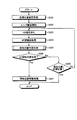
ここで、図9のステップS311で実施される開始位置決定処理の詳細について図10を用いて説明する。図10は、開始位置決定処理の一例を示すフローチャートである。開始位置決定処理が開始されると、開始スキャン処理部108−1は、まず、ピーク検出フラグがONであるか否か(ピーク検出時であるか否か)を判定する(ステップS401)。この判定の結果、ピーク検出フラグがONであった場合(ステップS401:Yes)、開始スキャン処理部108−1は、デジタルスチルカメラの電源がONされてからレリーズボタンSW1が押下されるまでの経過時間が予め定めた所定時間(例えば5秒)よりも短いか否かを判定し(ステップS402)、電源がONされてからの経過時間が所定時間より短ければ(ステップS402:Yes)、開始スキャン処理により検出されたピーク位置を合焦位置に設定し(ステップS403)、AFスキャン処理キャンセルフラグをONにして(ステップS404)、開始位置決定処理を終了する。 Here, details of the start position determination process performed in step S311 of FIG. 9 will be described with reference to FIG. FIG. 10 is a flowchart illustrating an example of the start position determination process. When the start position determination process is started, the start scan processing unit 108-1 first determines whether or not the peak detection flag is ON (whether or not it is a peak detection time) (step S401). As a result of this determination, if the peak detection flag is ON (step S401: Yes), the start scan processing unit 108-1 has elapsed from when the digital still camera is turned on until the release button SW1 is pressed. It is determined whether or not the time is shorter than a predetermined time (for example, 5 seconds) (step S402). If the elapsed time since the power is turned on is shorter than the predetermined time (step S402: Yes), the start scan is performed. The peak position detected by the process is set as the in-focus position (step S403), the AF scan process cancel flag is turned on (step S404), and the start position determination process is terminated.
開始スキャン処理により検出されたピーク位置は、AF評価値の平滑微分値がプラスからマイナス側に反転する位置として特定することができるが、開始スキャン処理においては、バックラッシュ分を除去しなければいけない方向でフォーカスレンズ7−2aを移動させているため、実際のピーク位置は、図11に示すように、AF評価値の平滑微分値がプラスからマイナス側に反転する位置から若干ずれた位置となる(以下、このずれを「スキャン方向差」という。)。そのため、ステップS403で設定する合焦位置としては、AF評価値の平滑微分値がプラスからマイナス側に反転する位置に対して、このスキャン方向差分ずらした位置を設定するようにする。このスキャン方向差に関しては、デジタルスチルカメラの機体によって差が出てくる場合があり、製造段階で調整された値になる場合があるが、本実施形態では、一律+2パルスとする。 The peak position detected by the start scan process can be specified as the position where the smooth differential value of the AF evaluation value is inverted from the plus side to the minus side. However, in the start scan process, the backlash must be removed. Since the focus lens 7-2a is moved in the direction, the actual peak position is slightly shifted from the position where the smooth differential value of the AF evaluation value is reversed from the plus side to the minus side, as shown in FIG. (Hereinafter, this deviation is referred to as “scan direction difference”). Therefore, as the in-focus position set in step S403, a position shifted by the difference in the scanning direction is set with respect to the position where the smooth differential value of the AF evaluation value is reversed from the plus side to the minus side. This difference in scan direction may vary depending on the body of the digital still camera and may have a value adjusted in the manufacturing stage, but in this embodiment, it is uniformly +2 pulses.
一方、ステップS402の判定の結果、電源がONされてからの経過時間が所定時間以上である場合は(ステップS402:No)、開始スキャン処理部108−1は、フォーカスレンズ7−2aの現在位置より「1」評価値手前の位置、つまり1つ前のAF評価値が取得された位置(以下、この位置を「ピーク検出時開始位置」という。)をAF開始位置に決定し(ステップS405)、開始位置決定処理を終了する。 On the other hand, if the result of determination in step S402 is that the elapsed time since the power was turned on is equal to or longer than the predetermined time (step S402: No), the start scan processing unit 108-1 determines the current position of the focus lens 7-2a The position before the “1” evaluation value, that is, the position from which the previous AF evaluation value was acquired (hereinafter, this position is referred to as “peak detection start position”) is determined as the AF start position (step S405). Then, the start position determination process ends.
また、ステップS401の判定の結果、ピーク検出フラグがOFFであった場合は(ステップS401:No)、開始スキャン処理部108−1は、遠側判定フラグがONであるか否か(遠側判定時であるか否か)を判定する(ステップS406)。そして、遠側判定フラグがONであった場合(ステップS406:Yes)、開始スキャン処理部108−1は、フォーカスレンズ7−2aの現在位置より「2」評価値手前の位置、つまり2つ前のAF評価値が取得された位置(以下、この位置を「遠側判定時開始位置」という。)をAF開始位置に決定し(ステップS407)、開始位置決定処理を終了する。一方、遠側判定フラグがOFFであった場合は(ステップS406:No)、開始スキャン処理部108−1は、AF開始位置を決定することなく、開始位置決定処理を終了する。 When the peak detection flag is OFF as a result of the determination in step S401 (step S401: No), the start scan processing unit 108-1 determines whether or not the far side determination flag is ON (far side determination). It is determined whether or not it is time (step S406). If the far-side determination flag is ON (step S406: Yes), the start scan processing unit 108-1 is a position “2” before the evaluation value from the current position of the focus lens 7-2a, that is, two before. The position at which the AF evaluation value is acquired (hereinafter, this position is referred to as “far-side determination start position”) is determined as the AF start position (step S407), and the start position determination process ends. On the other hand, when the far-side determination flag is OFF (step S406: No), the start scan processing unit 108-1 ends the start position determination process without determining the AF start position.
図12は、ピーク検出時および遠側判定時(単調下降時)におけるAF評価値の変化を表す波形の一例を示す図であり、縦軸がAF評価値の大きさ、横軸がフォーカスレンズ7−2aの位置を表している。また、図13は、ピーク検出時および遠側判定時(単調下降時)における平滑微分値の変化を表す波形の一例を示す図であり、縦軸が平滑微分値の大きさ、横軸がフォーカスレンズ7−2aの位置を表している。図12(a)および図13(a)が、それぞれピーク検出時の波形を示し、図12(b)および図13(b)が、それぞれ遠側判定時(単調下降時)の波形を示している。
FIG. 12 is a diagram illustrating an example of a waveform representing a change in AF evaluation value at the time of peak detection and at the time of far-side determination (during monotonous descent), where the vertical axis indicates the magnitude of the AF evaluation value, and the horizontal axis indicates the
ピーク検出時は、デジタルスチルカメラの電源がONされてからレリーズボタンSW1が押下されるまでの経過時間が所定時間(例えば5秒)以上であれば、図12(a)および図13(a)に示すように、最後に取得されたAF評価値から1つ手前の白丸で示す評価値が取得、つまり最後に算出された平滑微分値から1つ手前の白丸で示す平滑微分値が算出されたときのフォーカスレンズ7−2aの位置がピーク検出時開始位置であり、この位置がAF開始位置に設定される。そして、後のAFスキャン処理では、このAF開始位置からフォーカスレンズ7−2aを開始スキャン処理における移動方向とは逆方向(第2の方向)に移動させながら、合焦位置の検出が行われる。一方、ピーク検出時に、デジタルスチルカメラの電源がONされてからレリーズボタンSW1が押下されるまでの経過時間が所定時間(例えば5秒)よりも短ければ、図13(a)に示す平滑微分値がプラスからマイナス側に反転した位置からスキャン方向差分だけずらしたフォーカスレンズ7−2aの位置が合焦位置に設定され、合焦位置を検出するAFスキャン処理が省略される。 When the peak is detected, if the elapsed time from when the power of the digital still camera is turned on until the release button SW1 is pressed is equal to or longer than a predetermined time (for example, 5 seconds), FIG. 12 (a) and FIG. 13 (a). As shown in FIG. 6, the evaluation value indicated by the previous white circle is acquired from the AF evaluation value acquired last, that is, the smooth differential value indicated by the previous white circle is calculated from the last calculated smooth differential value. The position of the focus lens 7-2a at this time is the peak detection start position, and this position is set as the AF start position. In the subsequent AF scan process, the focus position is detected while moving the focus lens 7-2a from the AF start position in the direction opposite to the movement direction in the start scan process (second direction). On the other hand, if the elapsed time from when the digital still camera is turned on to when the release button SW1 is pressed is shorter than a predetermined time (for example, 5 seconds) at the time of peak detection, the smooth differential value shown in FIG. The position of the focus lens 7-2a shifted by the difference in the scanning direction from the position where the lens is inverted from the plus to the minus side is set as the in-focus position, and the AF scan process for detecting the in-focus position is omitted.
また、遠側判定時は、図12(b)および図13(b)に示すように、最後に取得されたAF評価値から2つ手前の白丸で示す評価値が取得、つまり最後に算出された平滑微分値から2つ手前の白丸で示す平滑微分値が算出されたときのフォーカスレンズ7−2aの位置が遠側判定時開始位置であり、この位置がAF開始位置に設定される。そして、後のAFスキャン処理では、このAF開始位置からフォーカスレンズ7−2aを開始スキャン処理における移動方向(第1の方向)とは逆方向(第2の方向)に移動させながら、合焦位置の検出が行われる。 In the far side determination, as shown in FIG. 12B and FIG. 13B, an evaluation value indicated by a white circle two before is acquired from the last acquired AF evaluation value, that is, calculated last. The position of the focus lens 7-2a when the smooth differential value indicated by the previous white circle is calculated from the smooth differential value is the far side determination start position, and this position is set as the AF start position. In the subsequent AF scan process, the focus lens 7-2a is moved from the AF start position in the opposite direction (second direction) to the movement direction (first direction) in the start scan process. Is detected.
開始スキャン処理においてフォーカスレンズ7−2aを移動させる第1の方向は、バックラッシュの影響を受ける方向、あるいはバックラッシュを除去する必要がある方向となるため、この開始スキャン処理において合焦位置を決めてしまうことは、合焦位置の精度として問題が生じることが多い。そこで、デジタルスチルカメラの電源がONされてから所定時間(例えば5秒)以上経過した後にレリーズボタンSW1が押下された状況においては、開始スキャン処理はあくまで次の処理であるAFスキャン処理の開始位置であるAF開始位置を決定するだけにとどめ、その後さらにAFスキャン処理を行うことで、合焦位置を精度よく検出できるようにする。一方、デジタルスチルカメラの電源がONされてからレリーズボタンSW1が押下されるまでの経過時間が所定時間(例えば5秒)よりも短い場合は、撮影者がすぐに撮影を行いたいと考えている可能性が高い状況であると推定されるため、スキャン方向差を加味したピーク位置を合焦位置とみなして、その後のAFスキャン処理を省略することで、AF動作をさらに高速化し、すぐに画像を撮影できるようにする。デジタルスチルカメラの電源がONされてからレリーズボタンSW1が押下されるまでの経過時間は、例えば、デジタルスチルカメラの内部に設けたタイマで経過時間をカウントすることにより計測できる。 Since the first direction in which the focus lens 7-2a is moved in the start scan process is a direction affected by backlash or a direction in which the backlash needs to be removed, the focus position is determined in the start scan process. This often causes a problem as the accuracy of the in-focus position. Therefore, in a situation where the release button SW1 is pressed after a predetermined time (for example, 5 seconds) has elapsed since the power of the digital still camera is turned on, the start scan process is the start position of the AF scan process, which is the next process. Only the AF start position is determined, and then AF scan processing is further performed so that the in-focus position can be detected with high accuracy. On the other hand, if the elapsed time from when the digital still camera is turned on until the release button SW1 is pressed is shorter than a predetermined time (for example, 5 seconds), the photographer wants to take a picture immediately. Since it is estimated that the situation is highly likely, the peak position with the difference in scan direction is regarded as the in-focus position, and the subsequent AF scan processing is omitted, so that the AF operation is further speeded up and the image is immediately displayed. To be able to shoot. The elapsed time from when the power of the digital still camera is turned on until the release button SW1 is pressed can be measured, for example, by counting the elapsed time with a timer provided inside the digital still camera.
図8に戻り、ステップS205の開始位置判定処理が終了すると、開始スキャン処理部108−1は、ステップS205の開始位置判定処理においてAF開始位置が決定されたか否かを判定する(ステップS206)。そして、AF開始位置が決定されている場合は(ステップS206:Yes)、開始スキャン処理部108−1は、決定されたAF開始位置にフォーカスレンズ7−2aを移動させて(ステップS207)、開始スキャン処理を終了する。一方、AF開始位置が決定されていない場合は(ステップS206:No)、開始スキャン処理部108−1は、フォーカスレンズ7−2aの現在位置がステップS201で設定した目標位置に到達したか否かを判定し(ステップS208)、フォーカスレンズ7−2aの現在位置が目標位置に到達していなければ(ステップS208:No)、ステップS203に戻って以降の処理を繰り返す。一方、フォーカスレンズ7−2aの現在位置が目標位置に到達している場合は(ステップS208:Yes)、開始スキャン処理部108−1は、フォーカスレンズ7−2aの現在位置、つまりステップS201で設定した目標位置をAF開始位置として、開始スキャン処理を終了する。 Returning to FIG. 8, when the start position determination process in step S205 is completed, the start scan processing unit 108-1 determines whether or not the AF start position is determined in the start position determination process in step S205 (step S206). If the AF start position is determined (step S206: Yes), the start scan processing unit 108-1 moves the focus lens 7-2a to the determined AF start position (step S207), and starts. The scan process ends. On the other hand, when the AF start position has not been determined (step S206: No), the start scan processing unit 108-1 determines whether or not the current position of the focus lens 7-2a has reached the target position set in step S201. (Step S208), and if the current position of the focus lens 7-2a has not reached the target position (step S208: No), the process returns to step S203 and the subsequent processing is repeated. On the other hand, when the current position of the focus lens 7-2a has reached the target position (step S208: Yes), the start scan processing unit 108-1 is set in the current position of the focus lens 7-2a, that is, step S201. The start scan process is terminated with the target position thus set as the AF start position.
図7に戻り、ステップS102の開始スキャン処理が終了すると、AFスキャン処理部(AF処理部)108−2によるAFスキャン処理が行われる(ステップS103)。ここで、図7のステップS103で実施されるAFスキャン処理の詳細について図14を用いて説明する。図14は、AFスキャン処理の一例を示すフローチャートである。AFスキャン処理が開始されると、AFスキャン処理部108−2は、まず、AFスキャン処理キャンセルフラグがOFFになっているか否かを判定する(ステップS501)。そして、AFスキャン処理キャンセルフラグがONになっている場合は(ステップS501:No)、すでに合焦位置が設定されているため、AFスキャン処理部108−2は、AFスキャン処理を終了する。 Returning to FIG. 7, when the start scan process in step S102 is completed, an AF scan process is performed by the AF scan processing unit (AF processing unit) 108-2 (step S103). Here, details of the AF scan processing performed in step S103 of FIG. 7 will be described with reference to FIG. FIG. 14 is a flowchart illustrating an example of AF scan processing. When the AF scan process is started, the AF scan processing unit 108-2 first determines whether or not the AF scan process cancel flag is OFF (step S501). If the AF scan process cancel flag is ON (step S501: No), since the in-focus position has already been set, the AF scan processing unit 108-2 ends the AF scan process.
一方、AFスキャン処理キャンセルフラグがOFFになっている場合は(ステップS501:Yes)、AFスキャン処理部108−2は、VD信号の立下がりを検出するまで待ち(ステップS502)、VD信号の立下がりを検出した後に、所定パルス数に応じてフォーカスモータ7−2bを駆動し、フォーカスレンズ7−2aをAF開始位置から第2の方向に所定量移動させる(ステップS503)。そして、AFスキャン処理部108−2は、フォーカスレンズ7−2aを移動させた後に入力される画像データからAF評価値を取得し(ステップS504)、このAF評価値より平滑微分演算処理を行う(ステップS505)。 On the other hand, when the AF scan processing cancel flag is OFF (step S501: Yes), the AF scan processing unit 108-2 waits until it detects the falling edge of the VD signal (step S502), and the rising edge of the VD signal. After detecting the fall, the focus motor 7-2b is driven according to a predetermined number of pulses, and the focus lens 7-2a is moved from the AF start position by a predetermined amount in the second direction (step S503). Then, the AF scan processing unit 108-2 acquires an AF evaluation value from image data input after the focus lens 7-2a is moved (step S504), and performs a smooth differential calculation process from the AF evaluation value ( Step S505).
次に、AFスキャン処理部108−2は、ステップS505で算出した平滑微分値に基づいて、ピーク位置を検出する処理を行う(ステップS506)。これは、上記の平滑微分値の符号が反転するフォーカスレンズ7−2aの位置を検出する処理である。そして、AFスキャン処理部108−2は、ステップS506の処理でピーク位置が検出されたか否かを判定し(ステップS507)、ピーク位置が検出された場合は(ステップS507:Yes)、AFスキャン処理を終了する。一方、ピーク位置が検出されない場合は(ステップS507:No)、AFスキャン処理部108−2は、フォーカスレンズ7−2aの現在位置がAFスキャン処理の終了位置に到達したか否かを判定し(ステップS508)、フォーカスレンズ7−2aの現在位置が終了位置に到達していなければ(ステップS508:No)、ステップS502に戻って以降の処理を繰り返す。一方、フォーカスレンズ7−2aの現在位置が終了位置に到達している場合は(ステップS508:Yes)、AFスキャン処理部108−2は、AFスキャン処理を終了する。 Next, the AF scan processing unit 108-2 performs processing for detecting a peak position based on the smooth differential value calculated in step S505 (step S506). This is a process of detecting the position of the focus lens 7-2a where the sign of the smooth differential value is inverted. Then, the AF scan processing unit 108-2 determines whether or not the peak position is detected in the process of step S506 (step S507). If the peak position is detected (step S507: Yes), the AF scan process is performed. Exit. On the other hand, when the peak position is not detected (step S507: No), the AF scan processing unit 108-2 determines whether or not the current position of the focus lens 7-2a has reached the end position of the AF scan process ( If the current position of the focus lens 7-2a has not reached the end position (step S508: No), the process returns to step S502 and the subsequent processing is repeated. On the other hand, when the current position of the focus lens 7-2a has reached the end position (step S508: Yes), the AF scan processing unit 108-2 ends the AF scan process.
図15は、上記のAFスキャン処理において、ステップS504で取得されるAF評価値の変化を表す波形の一例を示す図である。図15(a)は、被写体輝度がLV10の場合のAF評価値の波形、図15(b)は被写体輝度がLV8の場合のAF評価値の波形をそれぞれ示しており、縦軸がAF評価値の大きさ、横軸がフォーカスレンズ7−2aの位置を表している。図15(b)に示す例は、図15(a)に示す例よりも光量が少ない(暗い)環境で取得されたAF評価値の波形であり、隣接画素間の輝度差が微小であるため雑音の影響が大きく、AF評価値にバラツキが生じて複数のピーク位置が現われている。AF評価値のピーク位置(極大値)が図15(a)に示すように1カ所であれば、そこを合焦位置として設定すればよいが、図15(b)に示すように複数のピーク位置がある場合、どの位置を合焦位置とするかは単純に判定することはできない。 FIG. 15 is a diagram illustrating an example of a waveform representing a change in the AF evaluation value acquired in step S504 in the AF scan process. FIG. 15A shows the waveform of the AF evaluation value when the subject brightness is LV10, and FIG. 15B shows the waveform of the AF evaluation value when the subject brightness is LV8. The vertical axis indicates the AF evaluation value. The horizontal axis represents the position of the focus lens 7-2a. The example shown in FIG. 15B is a waveform of an AF evaluation value acquired in an environment where the amount of light is smaller (darker) than the example shown in FIG. 15A, and the luminance difference between adjacent pixels is very small. The influence of noise is large, the AF evaluation value varies, and a plurality of peak positions appear. If the peak position (maximum value) of the AF evaluation value is one as shown in FIG. 15A, it may be set as the in-focus position. However, as shown in FIG. If there is a position, it cannot be simply determined which position is the in-focus position.
図16は、上記のAFスキャン処理において、ステップS505で算出される平滑微分値の変化を表す波形の一例を示す図である。図16(a)は、図15(a)に示したAF評価値を元に算出された平滑微分値の波形、図16(b)は、図15(b)に示したAF評価値を元に算出された平滑微分値の波形を示しており、縦軸が平滑微分値の大きさ、横軸がフォーカスレンズ7−2aの位置を表している。図16(a)および図16(b)に示すように、所定数のAF評価値が取得されるまでは平滑微分値は算出されない。所定数のAF評価値が取得された後に算出される平滑微分値は、フォーカスレンズ7−2aの移動に伴って変位し、ある点で符号が反転する。この反転する点がAF評価値の極大値に相当し、そのときのフォーカスレンズ7−2aの位置がピーク位置である。すなわち、先に示した演算式によって算出された平滑微分値の符号が反転する位置、すなわち平滑微分値がゼロの位置がAF評価値の極大点となる。このように、平滑微分値の符号が反転するAF評価値が取得されたフォーカスレンズ7−2aの位置を特定することで、その位置を合焦位置に設定して、被写体に焦点があった画像を撮影することができる。 FIG. 16 is a diagram illustrating an example of a waveform representing a change in the smooth differential value calculated in step S505 in the AF scan process. 16A shows a waveform of a smooth differential value calculated based on the AF evaluation value shown in FIG. 15A, and FIG. 16B shows the AF evaluation value shown in FIG. 15B. 4 shows the waveform of the calculated smooth differential value, where the vertical axis represents the magnitude of the smooth differential value and the horizontal axis represents the position of the focus lens 7-2a. As shown in FIGS. 16A and 16B, the smooth differential value is not calculated until a predetermined number of AF evaluation values are acquired. The smooth differential value calculated after the predetermined number of AF evaluation values are acquired is displaced with the movement of the focus lens 7-2a, and the sign is inverted at a certain point. This inversion point corresponds to the maximum value of the AF evaluation value, and the position of the focus lens 7-2a at that time is the peak position. That is, the position where the sign of the smooth differential value calculated by the above-described arithmetic expression is inverted, that is, the position where the smooth differential value is zero is the maximum point of the AF evaluation value. In this way, by specifying the position of the focus lens 7-2a from which the AF evaluation value at which the sign of the smooth differential value is inverted is specified, the position is set as the in-focus position, and the subject is in focus. Can be taken.
図7に戻り、ステップS103のAFスキャン処理が終了すると、合焦位置決定処理部108−3による合焦位置決定処理が行われる(ステップS104)。合焦位置決定処理部108−3は、ステップS103のAFスキャン処理においてピーク位置が検出されている場合は、そのピーク位置を合焦位置と決定する。また、合焦位置決定処理部108−3は、AFスキャン処理においてピーク位置が検出されなかった場合はAFNGとして、NG位置を合焦位置と決定する。ここでのNG位置は、およそ2.5m程度離れた被写体に合焦するフォーカスレンズ7−2aの位置としている。なお、ステップS102の開始スキャン処理において合焦位置が設定され、ステップS103のAFスキャン処理が省略された場合は、合焦位置決定処理部108−3による合焦位置の決定は行われない。 Returning to FIG. 7, when the AF scan process in step S103 is completed, a focus position determination process is performed by the focus position determination processing unit 108-3 (step S104). When the peak position is detected in the AF scan process of step S103, the focus position determination processing unit 108-3 determines the peak position as the focus position. Further, when the peak position is not detected in the AF scan process, the focus position determination processing unit 108-3 determines the NG position as the focus position as AFNG. The NG position here is the position of the focus lens 7-2a that focuses on a subject about 2.5 m away. Note that when the in-focus position is set in the start scan process in step S102 and the AF scan process in step S103 is omitted, the in-focus position is not determined by the in-focus position determination processing unit 108-3.
そして、ステップS104の合焦位置決定処理が終了すると、最後に、合焦位置移動処理部108−4による合焦位置移動処理が行われる(ステップS105)。この合焦位置移動処理は、ステップS104の合焦位置決定処理で決定された合焦位置、あるいはステップS102の開始スキャン処理で設定された合焦位置に、フォーカスレンズ7−2aを移動させる処理である。 When the in-focus position determination process in step S104 is completed, the in-focus position movement process is finally performed by the in-focus position movement processing unit 108-4 (step S105). This in-focus position moving process is a process of moving the focus lens 7-2a to the in-focus position determined in the in-focus position determining process in step S104 or the in-focus position set in the start scan process in step S102. is there.
以上、具体的な例を挙げながら詳細に説明したように、本実施形態に係るデジタルスチルカメラによれば、開始スキャン処理部108−1による開始スキャン処理において、フォーカスレンズ7−2aが目標位置に移動するまでの間にAF評価値のピークが検出され、かつ、デジタルスチルカメラの電源がONされてからレリーズボタンSW1が押下されるまでの経過時間が所定時間(例えば5秒)よりも短い場合は、AF評価値のピークが検出されたフォーカスレンズ7−2aの位置を合焦位置とみなして、AFスキャン処理部108−2によるAFスキャン処理をキャンセルさせるので、撮影者がすぐに撮影を行いたい状況でAF動作をさらに高速化し、操作の応答性を高めることができる。 As described above in detail with specific examples, according to the digital still camera according to the present embodiment, the focus lens 7-2a is at the target position in the start scan processing by the start scan processing unit 108-1. When the peak of the AF evaluation value is detected before moving, and the elapsed time from when the digital still camera is turned on until the release button SW1 is pressed is shorter than a predetermined time (for example, 5 seconds) Considers the position of the focus lens 7-2a from which the peak of the AF evaluation value is detected as the in-focus position, and cancels the AF scan processing by the AF scan processing unit 108-2. In a desired situation, the AF operation can be further speeded up and the response of the operation can be improved.
また、本実施形態に係るデジタルスチルカメラによれば、開始スキャン処理部108−1による開始スキャン処理において、デジタルスチルカメラの電源がONされてからの経過時間が所定時間以上であれば、AF評価値を元に被写体状態を確認し、被写体状態に応じて適切なAF開始位置を決定するので、AF動作の高速化を図りながら、被写体に対して精度よく焦点を合わせることができる。 Further, according to the digital still camera according to the present embodiment, in the start scan processing by the start scan processing unit 108-1, if the elapsed time from turning on the power of the digital still camera is equal to or longer than a predetermined time, AF evaluation is performed. Since the subject state is confirmed based on the value and an appropriate AF start position is determined according to the subject state, the subject can be focused with high accuracy while speeding up the AF operation.
また、本実施形態に係るデジタルスチルカメラによれば、開始スキャン処理部108−1による開始スキャン処理において、AF評価値から平滑微分値を算出し、平滑微分値の変化からAF評価値のピークを検出するようにしているので、ピークの検出を精度よく行うことができる。また、本実施形態に係るデジタルスチルカメラによれば、AFスキャン処理部108−2によるAFスキャン処理においても、AF評価値から平滑微分値を算出し、平滑微分値の変化からAF評価値のピークを検出するようにしているので、ピークの検出を精度よく行うことができる。 Further, according to the digital still camera according to the present embodiment, in the start scan processing by the start scan processing unit 108-1, the smooth differential value is calculated from the AF evaluation value, and the peak of the AF evaluation value is obtained from the change of the smooth differential value. Since the detection is performed, the peak can be detected with high accuracy. Further, according to the digital still camera according to the present embodiment, even in the AF scan processing by the AF scan processing unit 108-2, the smooth differential value is calculated from the AF evaluation value, and the peak of the AF evaluation value is calculated from the change of the smooth differential value. Is detected, so that the peak can be detected with high accuracy.
なお、本実施形態では、デジタルスチルカメラの電源がONされてからレリーズボタンSW1が押下されるまでの経過時間の比較対象となる所定時間として5秒を例示したが、所定時間の長さはこれに限らず、デジタルスチルカメラの起動時間等を考慮した長さに設定してもよいし、この所定時間の長さを可変にしてもよい。また、この所定時間の長さを撮影者が設定するモードを設けるようにしてもよい。 In the present embodiment, 5 seconds is exemplified as the predetermined time to be compared with the elapsed time from when the power of the digital still camera is turned on until the release button SW1 is pressed, but the length of the predetermined time is However, the length may be set in consideration of the activation time of the digital still camera, or the length of the predetermined time may be variable. Further, a mode in which the photographer sets the length of the predetermined time may be provided.
(第2の実施形態)
次に、第2の実施形態について説明する。第2の実施形態は、開始スキャン処理部108−1による開始スキャン処理のうち、開始位置決定処理(図9のステップS311)の内容が上述した第1の実施形態と異なるものである。すなわち、第1の実施形態の開始位置決定処理では、ピーク検出フラグがONで、かつ、デジタルスチルカメラの電源ONからレリーズボタンSW1が押下されるまでの経過時間が所定時間(例えば5秒)よりも短い場合に、検出されたピーク位置を合焦位置に設定して、AFスキャン処理キャンセルフラグをONにした。これに対し、第2の実施形態の開始位置決定処理では、ピーク検出フラグがONで、かつ、レリーズボタンSW1が全押しされた場合に、検出されたピーク位置を合焦位置に設定して、AFスキャン処理キャンセルフラグをONにする。また、第1の実施形態の開始位置決定処理では、ピーク検出フラグがOFFで、かつ、遠側判定フラグがOFFの場合は、AF開始位置を決定せずに開始スキャン処理を継続させていた。これに対して、第2実施形態の開始位置決定処理では、ピーク検出フラグがOFFで、かつ、遠側判定フラグがOFFの場合であっても、レリーズボタンSW1が全押しされ、かつ、評価値カウント数が所定数を超える場合は、フォーカスレンズ7−2aの現在位置をAF開始位置とし、開始スキャン処理を終了させる。なお、第2の実施形態のデジタルスチルカメラの構成およびAF動作における開始位置決定処理以外の他の処理は上述した第1の実施形態と同様であるため、以下では、第1の実施形態とは異なる開始位置決定処理についてのみ説明し、第1の実施形態と重複する説明は省略する。
(Second Embodiment)
Next, a second embodiment will be described. The second embodiment is different from the first embodiment described above in the contents of the start position determination process (step S311 in FIG. 9) in the start scan process by the start scan processing unit 108-1. That is, in the start position determination process of the first embodiment, the elapsed time from when the peak detection flag is ON and when the release button SW1 is pressed after the digital still camera is turned on is less than a predetermined time (eg, 5 seconds). If the peak position is shorter, the detected peak position is set to the in-focus position, and the AF scan process cancel flag is turned ON. In contrast, in the start position determination process of the second embodiment, when the peak detection flag is ON and the release button SW1 is fully pressed, the detected peak position is set as the in-focus position, Set the AF scan processing cancel flag to ON. Further, in the start position determination process of the first embodiment, when the peak detection flag is OFF and the far side determination flag is OFF, the start scan process is continued without determining the AF start position. On the other hand, in the start position determination process of the second embodiment, even when the peak detection flag is OFF and the far side determination flag is OFF, the release button SW1 is fully pressed and the evaluation value When the count number exceeds the predetermined number, the current position of the focus lens 7-2a is set as the AF start position, and the start scan process is terminated. In addition, since processes other than the configuration of the digital still camera of the second embodiment and the start position determination process in the AF operation are the same as those of the first embodiment described above, the first embodiment will be described below. Only a different start position determination process will be described, and a description overlapping that of the first embodiment will be omitted.
図17は、第2実施形態の開始位置決定処理の一例を示すフローチャートである。第2実施形態の開始位置決定処理が開始されると、開始スキャン処理部108−1は、まず、ピーク検出フラグがONであるか否か(ピーク検出時であるか否か)を判定する(ステップS601)。この判定の結果、ピーク検出フラグがONであった場合(ステップS601:Yes)、開始スキャン処理部108−1は、レリーズボタンSW1が全押しされたか否かを判定し(ステップS602)、レリーズボタンSW1が全押しされた場合(ステップS602:Yes)、開始スキャン処理により検出されたピーク位置を合焦位置に設定し(ステップS603)、AFスキャン処理キャンセルフラグをONにして(ステップS604)、開始位置決定処理を終了する。 FIG. 17 is a flowchart illustrating an example of a start position determination process according to the second embodiment. When the start position determination process of the second embodiment is started, the start scan processing unit 108-1 first determines whether or not the peak detection flag is ON (whether or not it is during peak detection) ( Step S601). As a result of this determination, when the peak detection flag is ON (step S601: Yes), the start scan processing unit 108-1 determines whether or not the release button SW1 is fully pressed (step S602), and the release button. When SW1 is fully pressed (step S602: Yes), the peak position detected by the start scan process is set as the focus position (step S603), the AF scan process cancel flag is turned ON (step S604), and the process starts. The position determination process ends.
ステップS604で合焦位置として設定するピーク位置は、第1の実施形態と同様に、AF評価値の平滑微分値がプラスからマイナス側に反転する位置に対して、スキャン方向差分ずらした位置とする。このスキャン方向差に関しては、デジタルスチルカメラの機体によって差が出てくる場合があり、製造段階で調整された値になる場合があるが、本実施形態においても、第1の実施形態と同様に一律+2パルスとする。 As in the first embodiment, the peak position set as the in-focus position in step S604 is a position shifted by a difference in the scanning direction with respect to the position where the smooth differential value of the AF evaluation value is reversed from the plus side to the minus side. . Regarding this difference in scan direction, there may be a difference depending on the body of the digital still camera, and there may be a value adjusted in the manufacturing stage. However, in this embodiment as well, the same as in the first embodiment. Uniform +2 pulses.
一方、ステップS602の判定の結果、レリーズボタンSW1が半押しのままである場合は(ステップS602:No)、開始スキャン処理部108−1は、フォーカスレンズ7−2aの現在位置より「1」評価値手前のピーク検出時開始位置をAF開始位置に決定し、開始位置決定処理を終了する。 On the other hand, if the result of determination in step S602 is that the release button SW1 has been pressed halfway (step S602: No), the start scan processing unit 108-1 evaluates “1” from the current position of the focus lens 7-2a. The peak detection start position before the value is determined as the AF start position, and the start position determination process ends.
また、ステップS601の判定の結果、ピーク検出フラグがOFFであった場合は(ステップS601:No)、開始スキャン処理部108−1は、遠側判定フラグがONであるか否か(遠側判定時であるか否か)を判定する(ステップS606)。そして、遠側判定フラグがONであった場合(ステップS606:Yes)、開始スキャン処理部108−1は、フォーカスレンズ7−2aの現在位置より「2」評価値手前の遠側判定時開始位置をAF開始位置に決定し(ステップS607)、開始位置決定処理を終了する。 When the peak detection flag is OFF as a result of the determination in step S601 (step S601: No), the start scan processing unit 108-1 determines whether the far side determination flag is ON (far side determination). It is determined whether or not it is time (step S606). If the far-side determination flag is ON (step S606: Yes), the start scan processing unit 108-1 is the far-side determination start position that is “2” evaluation value before the current position of the focus lens 7-2a. Is determined as the AF start position (step S607), and the start position determination process ends.
一方、遠側判定フラグがOFFであった場合は(ステップS606:No)、開始スキャン処理部108−1は、次に、レリーズボタンSW1が全押しされたか否かを判定し(ステップS608)、レリーズボタンSW1が全押しされた場合(ステップS608:Yes)、AF評価値のカウント数が所定数(例えば「10」)より大きいか否かを判定する(ステップS609)。そして、AF評価値のカウント数が所定数より大きい場合は(ステップS609:Yes)、開始スキャン処理をこれ以上継続させてもピーク位置を検出できないと判断し、フォーカスレンズ7−2aの現在位置をAF開始位置に決定し(ステップS610)、開始位置決定処理を終了する。 On the other hand, if the far side determination flag is OFF (step S606: No), the start scan processing unit 108-1 next determines whether or not the release button SW1 is fully pressed (step S608). If the release button SW1 is fully pressed (step S608: Yes), it is determined whether or not the AF evaluation value count is greater than a predetermined number (eg, “10”) (step S609). If the count value of the AF evaluation value is greater than the predetermined number (step S609: Yes), it is determined that the peak position cannot be detected even if the start scan process is continued further, and the current position of the focus lens 7-2a is determined. The AF start position is determined (step S610), and the start position determination process ends.
一方、ステップS608でレリーズボタンSW1が半押しのままであると判定した場合や、(ステップS608:No)、ステップS609でAF評価値のカウント数が所定数以下であると判定した場合は、開始スキャン処理部108−1は、AF開始位置を決定することなく、開始位置決定処理を終了する。 On the other hand, if it is determined in step S608 that the release button SW1 is half pressed (step S608: No), or if it is determined in step S609 that the AF evaluation value count is equal to or less than a predetermined number, start. The scan processing unit 108-1 ends the start position determination process without determining the AF start position.
以上のように、本実施形態では、開始スキャン処理中にレリーズボタンSW1が全押しされた場合や、AF動作を開始させるトリガとなるレリーズボタンSW1の押下が半押しではなく全押しであった場合など、撮影者がすぐに撮影を行いたいと考えている可能性が高い状況では、開始スキャン処理においてピーク位置が検出された場合はそのピーク位置を合焦位置とみなして、その後のAFスキャン処理を省略することでAF動作をさらに高速化し、すぐに画像を撮影できるようにする。また、本実施形態では、開始スキャン処理においてAF評価値がある程度取得されている状態でピーク検出や遠側判定がなされていない場合は、フォーカスレンズ7−2aを目標位置に向かう第1の方向にさらに移動させてもピーク検出や遠側判定をすることが困難であると判断し、レリーズボタンSW1が全押しされている場合は、応答性を優先させてフォーカスレンズ7−2aの現在位置をAF開始位置に決定してすぐにAFスキャン処理に移行することで、AF動作をさらに高速化する。 As described above, in the present embodiment, when the release button SW1 is fully pressed during the start scan process, or when the release button SW1 that serves as a trigger for starting the AF operation is not half-pressed but fully pressed. In situations where there is a high possibility that the photographer wants to take an image immediately, such as when the peak position is detected in the start scan process, the peak position is regarded as the in-focus position, and the subsequent AF scan process By omitting, the AF operation is further speeded up so that an image can be taken immediately. In the present embodiment, when peak detection or far-side determination is not performed in a state where AF evaluation values are acquired to some extent in the start scan processing, the focus lens 7-2a is moved in the first direction toward the target position. If it is determined that it is difficult to detect the peak or the far side even if the lens is further moved, and the release button SW1 is fully pressed, priority is given to responsiveness and the current position of the focus lens 7-2a is set to AF. The AF operation is further speeded up by determining the start position and proceeding to AF scan processing immediately.
以上説明したように、本実施形態に係るデジタルスチルカメラによれば、開始スキャン処理部108−1による開始スキャン処理において、フォーカスレンズ7−2aが目標位置に移動するまでの間にAF評価値のピークが検出され、かつ、レリーズボタンSW1が全押しされた場合は、AF評価値のピークが検出されたフォーカスレンズ7−2aの位置を合焦位置とみなして、AFスキャン処理部108−2によるAFスキャン処理をキャンセルさせるので、撮影者がすぐに撮影を行いたい状況でAF動作をさらに高速化し、操作の応答性を高めることができる。 As described above, according to the digital still camera according to the present embodiment, in the start scan processing by the start scan processing unit 108-1, the AF evaluation value is measured before the focus lens 7-2a moves to the target position. When the peak is detected and the release button SW1 is fully pressed, the position of the focus lens 7-2a where the peak of the AF evaluation value is detected is regarded as the in-focus position, and the AF scan processing unit 108-2 Since the AF scanning process is canceled, the AF operation can be further speeded up and the responsiveness of the operation can be improved in a situation where the photographer wants to take a picture immediately.
また、本実施形態に係るデジタルスチルカメラによれば、開始スキャン処理部108−1による開始スキャン処理において、AF評価値がある程度取得されている状態でピーク検出や遠側判定がなされておらず、レリーズボタンSW1が全押しされている場合は、フォーカスレンズ7−2aの現在位置をAF開始位置に決定してすぐにAFスキャン処理に移行するようにしているので、AF動作をさらに高速化して操作の応答性を高めることができる。 Moreover, according to the digital still camera according to the present embodiment, in the start scan processing by the start scan processing unit 108-1, peak detection or far-side determination is not performed in a state where the AF evaluation value is acquired to some extent, When the release button SW1 is fully pressed, since the current position of the focus lens 7-2a is determined as the AF start position and the process immediately shifts to AF scan processing, the AF operation is further accelerated and operated. Can increase the responsiveness.
また、本実施形態に係るデジタルスチルカメラによれば、開始スキャン処理部108−1による開始スキャン処理において、レリーズボタンSW1が半押しのままであれば、AF評価値を元に被写体状態を確認し、被写体状態に応じて適切なAF開始位置を決定するので、AF動作の高速化を図りながら、被写体に対して精度よく焦点を合わせることができる。 Also, with the digital still camera according to the present embodiment, in the start scan processing by the start scan processing unit 108-1, if the release button SW1 remains half pressed, the subject state is confirmed based on the AF evaluation value. Since an appropriate AF start position is determined according to the subject state, it is possible to focus on the subject with high accuracy while speeding up the AF operation.
なお、本実施形態では、AF評価値がある程度取得されているかどうかの判断基準となる評価値カウント数の閾値として10を例示したが、AF評価値がある程度取得されているかどうかの判断基準となる評価値カウント数の閾値はこれに限らず、最適な値を適宜設定すればよい。 In this embodiment, 10 is exemplified as the threshold value of the evaluation value count number, which is a criterion for determining whether or not the AF evaluation value is acquired to some extent. The threshold value of the evaluation value count number is not limited to this, and an optimal value may be set as appropriate.
なお、上述した第1の実施形態と第2の実施形態では、応答性を優先させてAF動作をさらに高速化するための条件として、それぞれ、デジタルスチルカメラの電源がONされてからの経過時間が所定時間(例えば5秒)より短いという条件と、レリーズボタンSW1が全押しされたという条件を例示したが、これら2つの条件は、組み合わせて用いるようにしてもよいし、上記2つの条件以外の他の条件と組み合わせて用いるようにしてもよい。 In the first embodiment and the second embodiment described above, the time elapsed since the power of the digital still camera was turned on as a condition for further speeding up the AF operation by giving priority to responsiveness. The condition that is shorter than a predetermined time (for example, 5 seconds) and the condition that the release button SW1 is fully pressed are illustrated, but these two conditions may be used in combination, or other than the above two conditions It may be used in combination with other conditions.
なお、上述した第1の実施形態、第2の実施形態に係るデジタルスチルカメラにおいて特徴的なAF機能は、上述したように、一例としてプロセッサ104のCPUブロック104−3が実行する制御プログラムにより実現される。AF機能を実現するための制御プログラムは、例えば、デジタルスチルカメラのROM108に予め組み込まれて提供される。また、AF機能を実現するための制御プログラムを、インストール可能な形式または実行可能な形式のファイルでCD−ROM、フレキシブルディスク(FD)、CD−R、DVD(Digital Versatile Disc)などのコンピュータで読み取り可能な記録媒体に記録して提供するように構成してもよい。さらに、AF機能を実現するためのプログラムを、インターネット等のネットワークに接続されたコンピュータ上に格納し、ネットワーク経由でダウンロードさせることにより提供するように構成してもよい。また、AF機能を実現するためのプログラムを、インターネット等のネットワーク経由で提供または配布するように構成してもよい。
Note that the AF function characteristic of the digital still camera according to the first embodiment and the second embodiment described above is realized by a control program executed by the CPU block 104-3 of the
本実施形態に係るデジタルスチルカメラにおいてAF機能を実現させるための制御プログラムは、上述した開始スキャン処理部108−1、AFスキャン処理部108−2、合焦位置決定処理部108−3、および合焦位置移動処理部108−4の各処理機能を含むモジュール構成となっており、実際のハードウェアとしては、CPUブロック104−3が上記ROM108から制御プログラムを読み出して実行することにより、上記各処理機能がメインメモリ(例えばSDRAM103やRAM107)上にロードされ、上記各処理機能がメインメモリ上に生成されるようになっている。
The control program for realizing the AF function in the digital still camera according to the present embodiment includes the above-described start scan processing unit 108-1, AF scan processing unit 108-2, in-focus position determination processing unit 108-3, and focusing program. The module configuration includes each processing function of the focal position movement processing unit 108-4. As actual hardware, the CPU block 104-3 reads out and executes the control program from the
以上、本発明の具体的な実施形態について説明したが、本発明は、上述した実施形態そのままに限定されるものではなく、実施段階ではその要旨を逸脱しない範囲で様々な変形を加えて具体化することができる。つまり、上述したデジタルスチルカメラの構成や動作はあくまで具体的な一例を例示したものであり、用途や目的に応じて様々な変形が可能である。 Although specific embodiments of the present invention have been described above, the present invention is not limited to the above-described embodiments as they are, and is embodied by adding various modifications without departing from the scope of the invention in the implementation stage. can do. In other words, the configuration and operation of the digital still camera described above are merely specific examples, and various modifications can be made according to the application and purpose.
7−2a フォーカスレンズ
101 CCD
102 F/E−IC
104 デジタルスチルカメラプロセッサ
104−3 CPUブロック
108−1 開始スキャン処理部
108−2 AFスキャン処理部
SW1 レリーズボタン
7-
102 F / E-IC
104 Digital Still Camera Processor 104-3 CPU Block 108-1 Start Scan Processing Unit 108-2 AF Scan Processing Unit SW1 Release Button
Claims (8)
前記レンズを用いて撮像した被写体像を画像データとして出力する撮像部と、
前記レンズを第1の方向に移動させながら前記画像データからAF評価値を取得し、取得した前記AF評価値に基づいてAF開始位置を決定するAF開始位置決定部と、
前記レンズを前記AF開始位置から前記第1の方向とは逆方向である第2の方向に移動させながら前記画像データから前記AF評価値を取得し、取得した前記AF評価値に基づいて合焦位置を検出するAF処理部と、を備え、
前記AF開始位置決定部は、前記レンズが所定位置に移動するまでの間に前記AF評価値のピークが検出され、かつ、所定条件を満たす場合に、前記AF評価値のピークが検出された前記レンズの位置を前記合焦位置とみなして、前記AF処理部による前記合焦位置の検出をキャンセルさせることを特徴とする撮像装置。 A lens,
An imaging unit that outputs a subject image captured using the lens as image data;
An AF start position determination unit that acquires an AF evaluation value from the image data while moving the lens in a first direction, and determines an AF start position based on the acquired AF evaluation value;
The AF evaluation value is acquired from the image data while moving the lens from the AF start position in a second direction that is opposite to the first direction, and focusing is performed based on the acquired AF evaluation value. An AF processing unit for detecting a position,
The AF start position determination unit detects the peak of the AF evaluation value until the lens moves to a predetermined position, and the peak of the AF evaluation value is detected when a predetermined condition is satisfied. An imaging apparatus, wherein the position of the lens is regarded as the in-focus position, and the detection of the in-focus position by the AF processing unit is canceled.
前記所定条件は、前記スイッチが操作されたとの条件であることを特徴とする請求項1に記載の撮像装置。 With a switch to instruct the start of still image or video shooting,
The imaging apparatus according to claim 1, wherein the predetermined condition is a condition that the switch is operated.
前記AF開始位置決定部は、前記AF評価値のピークが検出されていない状態で前記スイッチが操作され、かつ、前記AF評価値を取得した回数が所定回数を超えた場合に、前記レンズの現在位置を前記AF開始位置に決定することを特徴とする請求項1に記載の撮像装置。 With a switch to instruct the start of still image or video shooting,
The AF start position determination unit operates when the switch is operated in a state where the peak of the AF evaluation value is not detected and the number of times the AF evaluation value is acquired exceeds a predetermined number. The imaging apparatus according to claim 1, wherein a position is determined as the AF start position.
前記レンズを第1の方向に移動させながら前記画像データからAF評価値を取得し、取得した前記AF評価値に基づいてAF開始位置を決定するAF開始位置決定工程と、
前記レンズを前記AF開始位置から前記第1の方向とは逆方向である第2の方向に移動させながら前記画像データから前記AF評価値を取得し、取得した前記AF評価値に基づいて合焦位置を検出するAF処理工程と、を含み、
前記AF開始位置決定工程において、前記レンズが所定位置に移動するまでの間に前記AF評価値のピークが検出され、かつ、所定条件を満たす場合に、前記AF評価値のピークが検出された前記レンズの位置を前記合焦位置とみなして、前記AF処理工程での前記合焦位置の検出を行わないことを特徴とする合焦位置検出方法。 A focus position detection method executed by an imaging apparatus including a lens and an imaging unit that outputs a subject image captured using the lens as image data,
An AF start position determining step of acquiring an AF evaluation value from the image data while moving the lens in a first direction, and determining an AF start position based on the acquired AF evaluation value;
The AF evaluation value is acquired from the image data while moving the lens from the AF start position in a second direction that is opposite to the first direction, and focusing is performed based on the acquired AF evaluation value. AF processing step for detecting the position,
In the AF start position determining step, the peak of the AF evaluation value is detected before the lens moves to a predetermined position, and the peak of the AF evaluation value is detected when a predetermined condition is satisfied. An in-focus position detecting method, wherein the position of the lens is regarded as the in-focus position, and the in-focus position is not detected in the AF processing step.
前記レンズを第1の方向に移動させながら前記画像データからAF評価値を取得し、取得した前記AF評価値に基づいてAF開始位置を決定する機能と、
前記レンズを前記AF開始位置から前記第1の方向とは逆方向である第2の方向に移動させながら前記画像データから前記AF評価値を取得し、取得した前記AF評価値に基づいて合焦位置を検出する機能と、を実現させる合焦位置検出プログラムであって、
前記AF開始位置を決定する機能は、前記レンズが所定位置に移動するまでの間に前記AF評価値のピークが検出され、かつ、所定条件を満たす場合に、前記AF評価値のピークが検出された前記レンズの位置を前記合焦位置とみなして、前記合焦位置の検出をキャンセルさせることを特徴とする合焦位置検出プログラム。 An imaging apparatus including a lens and an imaging unit that outputs a subject image captured using the lens as image data.
A function of acquiring an AF evaluation value from the image data while moving the lens in a first direction, and determining an AF start position based on the acquired AF evaluation value;
The AF evaluation value is acquired from the image data while moving the lens from the AF start position in a second direction that is opposite to the first direction, and focusing is performed based on the acquired AF evaluation value. A position detection program for realizing a position detection function,
The function of determining the AF start position is such that the peak of the AF evaluation value is detected before the lens moves to the predetermined position, and the peak of the AF evaluation value is detected when a predetermined condition is satisfied. Further, the focus position detection program cancels the detection of the focus position by regarding the position of the lens as the focus position.
Priority Applications (1)
| Application Number | Priority Date | Filing Date | Title |
|---|---|---|---|
| JP2012203568A JP2014059405A (en) | 2012-09-14 | 2012-09-14 | Imaging apparatus, focusing position detecting method, and focusing position detecting program |
Applications Claiming Priority (1)
| Application Number | Priority Date | Filing Date | Title |
|---|---|---|---|
| JP2012203568A JP2014059405A (en) | 2012-09-14 | 2012-09-14 | Imaging apparatus, focusing position detecting method, and focusing position detecting program |
Publications (2)
| Publication Number | Publication Date |
|---|---|
| JP2014059405A true JP2014059405A (en) | 2014-04-03 |
| JP2014059405A5 JP2014059405A5 (en) | 2015-07-23 |
Family
ID=50615937
Family Applications (1)
| Application Number | Title | Priority Date | Filing Date |
|---|---|---|---|
| JP2012203568A Pending JP2014059405A (en) | 2012-09-14 | 2012-09-14 | Imaging apparatus, focusing position detecting method, and focusing position detecting program |
Country Status (1)
| Country | Link |
|---|---|
| JP (1) | JP2014059405A (en) |
Cited By (1)
| Publication number | Priority date | Publication date | Assignee | Title |
|---|---|---|---|---|
| CN106101565A (en) * | 2016-08-22 | 2016-11-09 | 浙江宇视科技有限公司 | A kind of motor-driven lens focus method and device |
Citations (7)
| Publication number | Priority date | Publication date | Assignee | Title |
|---|---|---|---|---|
| JP2003295040A (en) * | 2002-03-29 | 2003-10-15 | Nikon Gijutsu Kobo:Kk | camera |
| JP2004085797A (en) * | 2002-08-26 | 2004-03-18 | Canon Inc | Automatic focusing apparatus, control method thereof, program and recording medium |
| JP2004191594A (en) * | 2002-12-10 | 2004-07-08 | Canon Inc | Automatic focusing device |
| JP2005037898A (en) * | 2003-06-30 | 2005-02-10 | Casio Comput Co Ltd | Imaging apparatus, autofocus control method, and autofocus control program |
| JP2007057974A (en) * | 2005-08-25 | 2007-03-08 | Fujifilm Holdings Corp | Imaging device |
| JP2011138103A (en) * | 2009-12-02 | 2011-07-14 | Ricoh Co Ltd | Imaging apparatus and method |
| JP2014056153A (en) * | 2012-09-13 | 2014-03-27 | Canon Inc | Focus adjustment device, imaging device, and control method therefor |
-
2012
- 2012-09-14 JP JP2012203568A patent/JP2014059405A/en active Pending
Patent Citations (7)
| Publication number | Priority date | Publication date | Assignee | Title |
|---|---|---|---|---|
| JP2003295040A (en) * | 2002-03-29 | 2003-10-15 | Nikon Gijutsu Kobo:Kk | camera |
| JP2004085797A (en) * | 2002-08-26 | 2004-03-18 | Canon Inc | Automatic focusing apparatus, control method thereof, program and recording medium |
| JP2004191594A (en) * | 2002-12-10 | 2004-07-08 | Canon Inc | Automatic focusing device |
| JP2005037898A (en) * | 2003-06-30 | 2005-02-10 | Casio Comput Co Ltd | Imaging apparatus, autofocus control method, and autofocus control program |
| JP2007057974A (en) * | 2005-08-25 | 2007-03-08 | Fujifilm Holdings Corp | Imaging device |
| JP2011138103A (en) * | 2009-12-02 | 2011-07-14 | Ricoh Co Ltd | Imaging apparatus and method |
| JP2014056153A (en) * | 2012-09-13 | 2014-03-27 | Canon Inc | Focus adjustment device, imaging device, and control method therefor |
Cited By (2)
| Publication number | Priority date | Publication date | Assignee | Title |
|---|---|---|---|---|
| CN106101565A (en) * | 2016-08-22 | 2016-11-09 | 浙江宇视科技有限公司 | A kind of motor-driven lens focus method and device |
| CN106101565B (en) * | 2016-08-22 | 2020-04-10 | 浙江宇视科技有限公司 | Electric lens focusing method and device |
Similar Documents
| Publication | Publication Date | Title |
|---|---|---|
| JP4979507B2 (en) | Imaging apparatus and imaging method | |
| JP5564996B2 (en) | Imaging apparatus and imaging method | |
| JP5820120B2 (en) | Imaging apparatus and control method thereof | |
| CN103460105B (en) | Imaging device and auto-focusing control method thereof | |
| JP6172428B2 (en) | Imaging apparatus and imaging method | |
| JP5325966B2 (en) | Imaging apparatus and imaging method | |
| JP5272551B2 (en) | Imaging apparatus and method | |
| KR101462323B1 (en) | Imaging device and imaging method | |
| JP2006121613A (en) | Imaging device | |
| JP5857610B2 (en) | Imaging apparatus and imaging method | |
| JP5178394B2 (en) | Imaging apparatus and control method thereof | |
| JP5011235B2 (en) | Imaging apparatus and imaging method | |
| JP4727534B2 (en) | Imaging device | |
| EP2445194B1 (en) | Imaging device and imaging method | |
| JP6136310B2 (en) | Imaging device | |
| JP5884579B2 (en) | Imaging apparatus and display processing method | |
| JP4855155B2 (en) | Imaging apparatus and imaging method using the same | |
| JP2014059405A (en) | Imaging apparatus, focusing position detecting method, and focusing position detecting program | |
| JP6257186B2 (en) | Imaging apparatus, imaging method, and program | |
| JP6305016B2 (en) | FOCUS CONTROL DEVICE, FOCUS CONTROL DEVICE CONTROL METHOD, AND IMAGING DEVICE | |
| JP5418553B2 (en) | Imaging apparatus and imaging method using the same | |
| JP4967930B2 (en) | Focus detection device | |
| JP2010122410A (en) | Imaging apparatus and imaging method | |
| JP2010204303A (en) | Imaging apparatus | |
| JP5093376B2 (en) | Imaging apparatus and program thereof |
Legal Events
| Date | Code | Title | Description |
|---|---|---|---|
| A521 | Request for written amendment filed |
Free format text: JAPANESE INTERMEDIATE CODE: A523 Effective date: 20150603 |
|
| A621 | Written request for application examination |
Free format text: JAPANESE INTERMEDIATE CODE: A621 Effective date: 20150603 |
|
| A977 | Report on retrieval |
Free format text: JAPANESE INTERMEDIATE CODE: A971007 Effective date: 20160323 |
|
| A131 | Notification of reasons for refusal |
Free format text: JAPANESE INTERMEDIATE CODE: A131 Effective date: 20160405 |
|
| A02 | Decision of refusal |
Free format text: JAPANESE INTERMEDIATE CODE: A02 Effective date: 20161101 |