JP2007192859A - Focus control device and imaging device - Google Patents
Focus control device and imaging device Download PDFInfo
- Publication number
- JP2007192859A JP2007192859A JP2006008379A JP2006008379A JP2007192859A JP 2007192859 A JP2007192859 A JP 2007192859A JP 2006008379 A JP2006008379 A JP 2006008379A JP 2006008379 A JP2006008379 A JP 2006008379A JP 2007192859 A JP2007192859 A JP 2007192859A
- Authority
- JP
- Japan
- Prior art keywords
- focus
- evaluation value
- lens
- control
- filters
- Prior art date
- Legal status (The legal status is an assumption and is not a legal conclusion. Google has not performed a legal analysis and makes no representation as to the accuracy of the status listed.)
- Abandoned
Links
Images




Classifications
-
- G—PHYSICS
- G02—OPTICS
- G02B—OPTICAL ELEMENTS, SYSTEMS OR APPARATUS
- G02B7/00—Mountings, adjusting means, or light-tight connections, for optical elements
- G02B7/28—Systems for automatic generation of focusing signals
- G02B7/36—Systems for automatic generation of focusing signals using image sharpness techniques, e.g. image processing techniques for generating autofocus signals
- G02B7/365—Systems for automatic generation of focusing signals using image sharpness techniques, e.g. image processing techniques for generating autofocus signals by analysis of the spatial frequency components of the image
-
- G—PHYSICS
- G03—PHOTOGRAPHY; CINEMATOGRAPHY; ANALOGOUS TECHNIQUES USING WAVES OTHER THAN OPTICAL WAVES; ELECTROGRAPHY; HOLOGRAPHY
- G03B—APPARATUS OR ARRANGEMENTS FOR TAKING PHOTOGRAPHS OR FOR PROJECTING OR VIEWING THEM; APPARATUS OR ARRANGEMENTS EMPLOYING ANALOGOUS TECHNIQUES USING WAVES OTHER THAN OPTICAL WAVES; ACCESSORIES THEREFOR
- G03B13/00—Viewfinders; Focusing aids for cameras; Means for focusing for cameras; Autofocus systems for cameras
- G03B13/32—Means for focusing
- G03B13/34—Power focusing
- G03B13/36—Autofocus systems
-
- H—ELECTRICITY
- H04—ELECTRIC COMMUNICATION TECHNIQUE
- H04N—PICTORIAL COMMUNICATION, e.g. TELEVISION
- H04N23/00—Cameras or camera modules comprising electronic image sensors; Control thereof
- H04N23/60—Control of cameras or camera modules
- H04N23/67—Focus control based on electronic image sensor signals
- H04N23/672—Focus control based on electronic image sensor signals based on the phase difference signals
-
- H—ELECTRICITY
- H04—ELECTRIC COMMUNICATION TECHNIQUE
- H04N—PICTORIAL COMMUNICATION, e.g. TELEVISION
- H04N23/00—Cameras or camera modules comprising electronic image sensors; Control thereof
- H04N23/60—Control of cameras or camera modules
- H04N23/67—Focus control based on electronic image sensor signals
- H04N23/673—Focus control based on electronic image sensor signals based on contrast or high frequency components of image signals, e.g. hill climbing method
-
- H—ELECTRICITY
- H04—ELECTRIC COMMUNICATION TECHNIQUE
- H04N—PICTORIAL COMMUNICATION, e.g. TELEVISION
- H04N5/00—Details of television systems
- H04N5/76—Television signal recording
- H04N5/765—Interface circuits between an apparatus for recording and another apparatus
- H04N5/77—Interface circuits between an apparatus for recording and another apparatus between a recording apparatus and a television camera
- H04N5/772—Interface circuits between an apparatus for recording and another apparatus between a recording apparatus and a television camera the recording apparatus and the television camera being placed in the same enclosure
-
- H—ELECTRICITY
- H04—ELECTRIC COMMUNICATION TECHNIQUE
- H04N—PICTORIAL COMMUNICATION, e.g. TELEVISION
- H04N2101/00—Still video cameras
Landscapes
- Engineering & Computer Science (AREA)
- Physics & Mathematics (AREA)
- Multimedia (AREA)
- Signal Processing (AREA)
- General Physics & Mathematics (AREA)
- Computer Vision & Pattern Recognition (AREA)
- Optics & Photonics (AREA)
- Automatic Focus Adjustment (AREA)
- Studio Devices (AREA)
- Focusing (AREA)
Abstract
【課題】種々の被写体に対して高精度の合焦制御を実現することができる技術を提供する。
【解決手段】本撮影前のコントラストAF制御において、AF回路600に備えられた相互に周波数特性が異なるハイパスフィルタ601、及びバンドパスフィルタ602〜604のうち、ハイパスフィルタ601を用いて取得されたAF評価値を最優先に使用して、フォーカスレンズ2aのレンズ合焦位置を検出する。このように、一般的な被写体を撮影する際に画像データにおいて増加する高周波帯域の成分を重視して抽出するHPF601を優先的に使用するように設定されているため、種々の被写体に対して高精度の合焦制御を行うことができる。
【選択図】図6
Provided is a technique capable of realizing high-precision focusing control for various subjects.
In contrast AF control before actual photographing, AF acquired using a high-pass filter 601 out of a high-pass filter 601 and band-pass filters 602 to 604 provided in an AF circuit 600 having different frequency characteristics. Using the evaluation value with the highest priority, the focus position of the focus lens 2a is detected. As described above, since the HPF 601 that extracts the high frequency band component that increases in the image data when the general subject is photographed is preferentially used, it is set to be used for various subjects. Accurate focusing control can be performed.
[Selection] Figure 6
Description
本発明は、合焦制御技術に関する。 The present invention relates to a focus control technique.
従来、銀塩カメラ等の撮像装置で実施されるオートフォーカス(AF)制御としては、いわゆる位相差方式を採用したものが多かった。しかし、この位相差方式のAF制御は、特に小さなFナンバーでの撮影においては、精度が良くないことが知られている。 Conventionally, as an autofocus (AF) control performed by an imaging apparatus such as a silver salt camera, there are many that employ a so-called phase difference method. However, it is known that this phase difference AF control is not accurate particularly in photographing with a small F number.
一方、近年では、デジタルカメラの登場とともに、いわゆるコントラスト方式(山登り方式)のAF制御が採用された撮像装置が広く普及している。そして、一般に、コントラスト方式のAF制御の方が、位相差方式のAF制御よりもAF精度が高いことが知られている。 On the other hand, in recent years, with the advent of digital cameras, imaging devices employing so-called contrast type (mountain climbing) AF control have become widespread. In general, it is known that the AF control of the contrast method has higher AF accuracy than the AF control of the phase difference method.
そこで、位相差方式とコントラスト方式のAF制御を併用することで、AF精度の向上を図ることが考えられる。 Therefore, it is conceivable to improve AF accuracy by using both phase difference type and contrast type AF control.
ところで、コントラスト方式のAF制御では、より高い周波数成分が多くなれば被写体画像が鮮鋭であると感じる人間の視覚特性に基づいて、ハイパスフィルタ等を用いて抽出された高周波成分を評価値として用いるのが一般的である。 By the way, in contrast-type AF control, a high-frequency component extracted using a high-pass filter or the like is used as an evaluation value based on human visual characteristics that a subject image feels sharper when higher frequency components increase. Is common.
しかし、撮影レンズによっては、被写体画像データから抽出される周波数帯域毎におけるMTF(Modulation Transfer Function)のピーク特性が異なるために、周波数帯域毎における評価値のピーク位置がずれてしまうことがある。例えば、図20に示すように、ナイキスト周波数fnの0.1倍(0.1fn)、0.3倍(0.3fn)、及び0.4倍(0.4fn)の3つの周波数について、MTFが最大となる像面位置がそれぞれ異なることがある。したがって、幅広い高周波帯域の成分を抽出する一般的なハイパスフィルタを用いると、周波数帯域毎におけるMTFのずれに起因して、高周波成分を用いた評価値のピークが分散して、ピーク検出ができなくなり、フォーカスレンズの合焦位置が検出し難くなることがある。 However, depending on the photographing lens, the peak characteristics of the MTF (Modulation Transfer Function) for each frequency band extracted from the subject image data are different, and therefore the peak position of the evaluation value for each frequency band may shift. For example, as shown in FIG. 20, for three frequencies of 0.1 times (0.1 fn), 0.3 times (0.3 fn), and 0.4 times (0.4 fn) of the Nyquist frequency fn, the MTF There are cases where the image plane position at which the maximum is different is different. Therefore, when a general high-pass filter that extracts a wide range of high frequency band components is used, the peak of the evaluation value using the high frequency components is dispersed due to the MTF shift in each frequency band, and peak detection becomes impossible. The focus position of the focus lens may be difficult to detect.
また、被写体によっては、コントラストが比較的低く、画像に含まれる高周波成分が比較的少ない場合もある。このような場合には、低周波成分(0.1fn)でピーク検出してしまい、視覚特性にマッチした高周波ピーク(0.3fn以上)でズレが生じ、被写体に対して適正に合焦させることが難しい。 Depending on the subject, the contrast may be relatively low, and the high-frequency component included in the image may be relatively small. In such a case, the peak is detected with a low-frequency component (0.1 fn), a shift occurs at a high-frequency peak (0.3 fn or more) that matches the visual characteristics, and the subject is properly focused. Is difficult.
以上の問題点に対して、相互に周波数特性が異なる複数のフィルタを用いて、被写体画像から相互に異なる複数の周波数帯域の成分を抽出してAF制御を行うことが考えられるが、どの周波数成分を用いてAF制御を行うのか決定することは難しい。 To deal with the above problems, it is conceivable to perform AF control by extracting components of a plurality of different frequency bands from the subject image using a plurality of filters having different frequency characteristics. It is difficult to determine whether to perform AF control using
このような問題に対し、相互に異なる複数の高周波帯域別の評価値に基づいて、それぞれ合焦位置までのフォーカスレンズの移動すべき距離(移動距離)を算出し、複数の移動距離と複数の高周波帯域を変数とするメンバーシップ関数とから複数の適合度を決定して、フォーカスレンズの移動距離を決定する技術が提案されている(例えば、特許文献1)。 For such a problem, based on evaluation values for a plurality of mutually different high frequency bands, the distance (movement distance) to which the focus lens should move to the in-focus position is calculated, and the plurality of movement distances and the plurality of movement distances are calculated. A technique for determining a moving distance of a focus lens by determining a plurality of fitnesses from a membership function having a high frequency band as a variable has been proposed (for example, Patent Document 1).
しかしながら、特許文献1で提案されている技術では、メンバーシップ関数を決定することが難しく、精度の高いAF制御を行うことは困難である。
However, with the technique proposed in
本発明は、上記課題に鑑みてなされたものであり、種々の被写体に対して高精度の合焦制御を実現することができる技術を提供することを目的とする。 The present invention has been made in view of the above problems, and an object of the present invention is to provide a technique capable of realizing high-precision focusing control for various subjects.
上記の課題を解決するために、請求項1の発明は、撮像装置の合焦制御を行う合焦制御装置であって、光学レンズを光軸に沿って駆動させている間に、当該光学レンズを介して入射される被写体からの光に基づいて複数の画像データを時間順次に取得する画像取得手段と、前記複数の画像データを相互に周波数特性が異なる複数のフィルタを用いてそれぞれ処理して、前記複数のフィルタを構成するフィルタ毎に評価値群を取得する評価値取得手段と、前記評価値取得手段において前記複数のフィルタのうちの所定のフィルタを用いた処理によって取得された評価値群を、前記複数のフィルタのうちの前記所定のフィルタとは異なる他のフィルタを用いた処理によって取得された評価値群よりも優先的に用いて、前記光学レンズの合焦位置を検出する合焦検出手段とを備えることを特徴とする。
In order to solve the above-described problems, the invention of
また、請求項2の発明は、請求項1に記載の合焦制御装置であって、前記所定のフィルタが、前記複数のフィルタのうちの前記所定のフィルタとは異なる他のフィルタよりも相対的に高い周波数帯域の成分を重視して抽出する周波数特性を有することを特徴とする。
The invention according to
また、請求項3の発明は、請求項1に記載の合焦制御装置であって、前記合焦検出手段が、前記複数のフィルタのうちの相対的に高い周波数帯域の成分を重視して抽出する周波数特性を有するフィルタによって取得された評価値群を優先的に用いて、前記合焦位置を検出することを特徴とする。
The invention according to
また、請求項4の発明は、請求項1に記載の合焦制御装置であって、前記所定のフィルタが、前記複数のフィルタのうちの前記所定のフィルタとは異なる他のフィルタよりも相対的に所定の周波数帯域の成分を重視して抽出する周波数特性を有することを特徴とする。
The invention according to
また、請求項5の発明は、請求項1から請求項4のいずれかに記載の合焦制御装置であって、位相差方式を用いて前記光学レンズの合焦位置を検出する位相差検出手段と、前記被写体からの光を、前記合焦検出手段及び前記位相差検出手段に対してそれぞれ導く第1及び第2の光路に分割する光分割手段とを更に備え、前記位相差検出手段を用いた合焦制御と、前記合焦検出手段を用いた合焦制御とが並行して実行されることを特徴とする。
The invention according to
また、請求項6の発明は、請求項5に記載の合焦制御装置であって、前記合焦検出手段が、前記位相差検出手段に係る合焦面とは相対的に異なる光学的な位置に合焦面を有し、前記合焦制御装置が、前記位相差検出手段を用いた合焦制御の開始後に、前記合焦検出手段を用いた合焦制御を開始するタイミング制御手段を更に備えることを特徴とする。
The invention according to
また、請求項7の発明は、請求項1から請求項6のいずれかに記載の合焦制御装置を搭載したことを特徴とする。
The invention according to
請求項1に記載の発明によれば、複数のフィルタのうちの所定のフィルタを用いて取得された評価値を優先的に使用して光学レンズの合焦位置を検出することで、例えば、一般的な被写体を撮影する際に高まる周波数を重視して抽出する所定のフィルタを優先的に使用するように設定すれば、種々の被写体に対して高精度の合焦制御を実現することができる。 According to the first aspect of the present invention, the evaluation value acquired using a predetermined filter among the plurality of filters is preferentially used to detect the in-focus position of the optical lens. If it is set to preferentially use a predetermined filter that is extracted with an emphasis on the frequency that is increased when photographing a typical subject, high-precision focusing control can be realized for various subjects.
また、請求項2及び請求項3のいずれに記載の発明によっても、複数のフィルタのうちの相対的に高い周波数帯域の成分を重視して抽出する周波数特性を有する所定のフィルタを用いて取得された評価値を優先的に使用して、光学レンズの合焦位置を検出することで、例えば、より高い周波数成分が多くなれば被写体画像が鮮鋭であると感じる人間の視覚特性に対応した合焦制御が可能となるため、高精度の合焦制御ができる。
Also, according to the invention described in any one of
また、請求項4に記載の発明によれば、複数のフィルタのうちの他のフィルタよりも相対的に所定の周波数帯域の成分を重視して抽出する周波数特性を有する所定のフィルタを用いて取得された評価値を優先的に使用して、光学レンズの合焦位置を検出することで、例えば、一般的な被写体を捉えた画像が合焦状態にある場合に増加する所定の高周波帯域の成分を重視した合焦制御が可能となるため、高精度の合焦制御ができる。
According to the invention described in
また、請求項5に記載の発明によれば、被写体からの光を2つの光路に分割して、分割された各光を用いて位相差方式の合焦制御とコントラスト方式の合焦制御とを並行して実施することで、例えば、位相差方式の合焦制御によって光学レンズを合焦位置近傍まで短時間で駆動させるとともに、コントラスト方式の合焦制御によって合焦制御の精度を確保することができるため、高速かつ精度の良い合焦制御が可能となる。 According to the fifth aspect of the present invention, the light from the subject is divided into two optical paths, and the phase difference type focusing control and the contrast type focusing control are performed using each of the divided lights. By carrying out in parallel, for example, the optical lens can be driven to the vicinity of the in-focus position in a short time by phase difference type focus control, and the accuracy of focus control can be ensured by contrast type focus control. Therefore, high-speed and accurate focusing control is possible.
また、請求項6に記載の発明によれば、位相差方式及びコントラスト方式の合焦検出に係る合焦面の光学的な位置を相互に異ならせ、位相差方式の合焦制御の開始後に、コントラスト方式の合焦制御が開始される構成により、同時に2つの合焦制御が行われ、位相差方式の合焦制御による合焦状態の実現前に、コントラスト方式の合焦制御によってフォーカスレンズのレンズ合焦位置を検出することができるため、高速かつ高精度の合焦制御を実現することができる。また、例えば、フォーカスレンズを逆向きに移動させることなく合焦制御を行うことができるため、バックラッシュの問題の発生を防止することができる。更に、例えば、ファインダ等を介して視認される被写体が、ぼけた状態から合焦状態へとスムーズに変化するような合焦制御を行うことができるため、合焦フィーリングを向上させることができる。
Further, according to the invention described in
また、請求項7に記載の発明によれば、請求項1から請求項6に記載の発明と同様な効果を得ることができる。 According to the seventh aspect of the invention, the same effects as those of the first to sixth aspects of the invention can be obtained.
以下、本発明の実施形態を図面に基づいて説明する。 Hereinafter, embodiments of the present invention will be described with reference to the drawings.
<撮像装置の概要>
図1は、本発明の実施形態に係る撮像装置1の概略構成を示す断面模式図である。
<Outline of imaging device>
FIG. 1 is a schematic cross-sectional view illustrating a schematic configuration of an
図1に示すように、撮像装置1は、いわゆる一眼レフ方式のデジタルカメラとして構成され、被写体からの光を撮影レンズユニット2を介して撮像装置本体300に導くことで、被写体に係る撮影画像データ(撮影画像)を得ることができる。撮像装置本体300には、撮像装置1においてオートフォーカス(AF)制御を行うためのユニット(以下「AF制御ユニット」とも「合焦制御装置」とも称する)100が搭載されている。また、撮影レンズユニット2には、撮影レンズユニット2の光軸L上において、AF制御を実現するためのレンズ(フォーカスレンズ)を含む複数の撮影レンズからなるレンズ群が配設される。
As illustrated in FIG. 1, the
図2は、撮像装置1の構成うちのAF制御ユニット100に係る構成に着目した模式図である。
FIG. 2 is a schematic diagram focusing on the configuration related to the
AF制御ユニット100は、主に、主ミラー10、サブミラー20、シャッター機構4、撮像素子であるC−MOSセンサ(以下「C−MOS」と略する)5、及び位相差AFモジュール3を備えて構成される。
The
主ミラー10は、ハーフミラーにより構成され、被写体からの光の一部を撮像装置本体300の上部に向けて反射することで反射光(以下「第1反射光」とも称する)をファインダー光学系に導く。具体的には、主ミラー10は、被写体からの光を反射することで、ファインダー焦点板6に被写体像を投影する。この被写体像はペンタプリズム7によって正立像化され、接眼レンズ8を介してユーザーが被写体像の状況を確認することができる。また、主ミラー10は、サブミラー20に向けて被写体からの光の一部を透過させる。
The
サブミラー20は、ハーフミラーにより構成され、被写体からの光のうち、主ミラー10を透過した光(以下「第1透過光」とも称する)を撮像装置本体300の下部に向けて反射することで、位相差AFモジュール3に導く。その一方で、サブミラー20は、C−MOS5に向けて第1透過光の一部を透過させる。つまり、サブミラー20は、被写体からの光を位相差AFモジュール3とC−MOS5とにそれぞれ導く2つの光路に分割する(分岐させる)。
The
位相差AFモジュール3は、位相差方式を用いた合焦検出を行うユニットである。位相差AFモジュール3は、コンデンサーレンズ3a、ミラー3b、セパレータレンズ3c、及び位相差検出用素子3dを備える。
The phase
コンデンサーレンズ3aは、サブミラー20によって反射された光(以下「第2反射光」とも称する)を位相差AFモジュール3内部に導く。ミラー3bは、第2反射光をセパレータレンズ3c側に向けて屈曲させる。セパレータレンズ3cは、位相差の検出を行う為の瞳分割用のレンズであり、第2反射光を瞳分割して、位相差検出用素子3dに投影させる。
The
図3から図5は、位相差方式の合焦制御の原理を説明するための図である。位相差方式の合焦制御では、図3から図5に示すように、合焦させたい被写体の表面(被写体面)PPから発せられた光FFを、撮影レンズユニット2、コンデンサーレンズ3a、及びセパレータレンズ3cを介して、位相差検出用素子3dに導く。このとき位相差検出用素子3dで検出される2つの被写体像の位相差、すなわち像間隔の変位量を測定してデフォーカス量を求める。ここでは、後述する撮像ホーム位置に設定されたC−MOS5の撮像面と等価な面(以下「撮像等価面」とも称する)FPで合焦するようにデフォーカス量が求められる。つまり、撮像等価面FPは、位相差方式のAF制御(位相差AF制御)によって合焦状態の被写体像が結像される面(以下「第1合焦面」とも称する)として構成される。
3 to 5 are diagrams for explaining the principle of phase difference focusing control. In the phase-difference focusing control, as shown in FIGS. 3 to 5, the light FF emitted from the surface (subject surface) PP of the subject to be focused is used as the photographing
なお、例えば、図3に示すように被写体に対して合焦している場合には、像間隔が位相差AFモジュール3の設計時に決められた所定値となるが、図4に示すように前ピンなら像間隔が狭くなり、図5に示すように後ピンであれば像間隔が広くなる。
For example, when the subject is in focus as shown in FIG. 3, the image interval is a predetermined value determined when the phase
シャッター機構4は、サブミラー20を透過した光(以下「第2透過光」とも称する)の光路を開放/遮断することが可能であり、光路を開放することで、第2透過光をC−MOS5上に照射させ、被写体像をC−MOS5上に投影させる。
The
C−MOS5は、被写体からの光のうちの第2透過光を受け付けることで画像信号を得る。C−MOS5によって得られる画像信号は、記録用の撮影画像データを生成するために使用される一方、記録用の撮影画像データを取得する動作(本撮影動作)前に、いわゆるコントラスト方式のAF制御(コントラストAF制御)を行うためにも使用される。C−MOS5の受光面(撮像面)は、コントラストAF制御によって合焦状態の被写体像が結像される面(以下「第2合焦面」とも称する)として構成される。
The C-
また、C−MOS5は、撮像装置本体300に対して移動可能に保持されているため、第2透過光の光軸Lに沿って前後に移動可能である。このC−MOS5の前後移動により、第1合焦面の光学的な位置に対して第2合焦面の光学的な位置が相互に異なる位置へと設定される。
Further, since the C-
なお、ここで言う「光学的な位置が相互に異なる」とは、第1合焦面において被写体像が合焦状態となるときに、第2合焦面において被写体像が合焦状態にはならないことを示しており、更に、第2合焦面において被写体像が合焦状態となるときに、第1合焦面において被写体像が合焦状態にはならないことを示している。 Here, “the optical positions are different from each other” means that the subject image is not in focus on the second focus surface when the subject image is in focus on the first focus surface. Furthermore, when the subject image is in focus on the second focus surface, the subject image is not in focus on the first focus surface.
<撮像装置の機能構成>
図6は、本発明の第1実施形態に係る撮像装置1の機能構成を例示するブロック図である。
<Functional configuration of imaging device>
FIG. 6 is a block diagram illustrating a functional configuration of the
図6に示すように、撮像装置1は、撮影レンズユニット2、位相差AFモジュール3、C−MOS5、ミラー機構10a、サブミラー機構20a、制御部101、レンズ位置検出部201、操作部OP、C−MOS移動制御部150、フォーカス制御部130、信号処理回路500、及びAF回路600等を備える。
As shown in FIG. 6, the
撮影レンズユニット2は、C−MOS5で取得される画像信号において被写体が合焦状態となるような合焦状態を実現するための光学レンズ(フォーカスレンズ)2a等を備える。フォーカスレンズ2aは、レンズの光軸に沿って前後に移動可能であり、フォーカス制御部130からの制御信号に応答してモータM1が駆動することで、フォーカスレンズ2aのレンズ位置が移動される。フォーカス制御部130は、制御部101から入力される制御信号に基づいて制御信号を生成する。また、フォーカスレンズ2aの位置は、レンズ位置検出部201によって検出され、フォーカスレンズ2aの位置を示すデータが制御部101に送られる。
The photographing
ミラー機構10aは、被写体からの光の経路(光路)から退避可能な主ミラー10を含む機構であり、ミラー制御部110からの制御信号に応答してモータM2が駆動することで、主ミラー10が光路から退避した状態(ミラーアップ状態)または光路を遮断した状態(ミラーダウン状態)に設定される。ミラー制御部110は、制御部101から入力される信号に基づいて制御信号を生成する。
The
サブミラー機構20aは、被写体からの光の経路から退避可能なサブミラー20を含む機構であり、サブミラー制御部120からの制御信号に応答してモータM5が駆動することで、サブミラー20が光路から退避した状態(ミラーアップ状態)または光路を遮断した状態(ミラーダウン状態)に設定される。サブミラー制御部120は、制御部101から入力される信号に基づいて制御信号を生成する。
The
シャッター機構4は、被写体からの光の経路を遮断/開放可能な機構であり、シャッタ制御部140からの制御信号に応答してモータM3が駆動することで、シャッター機構4が開閉する。シャッタ制御部140は、制御部101から入力される信号に基づいて制御信号を生成する。
The
C−MOS5は、撮像(光電変換)を行い、撮像画像に係る画像信号を生成する。C−MOS5は、タイミング制御回路170から入力される駆動制御信号(蓄積開始信号・蓄積終了信号)に応答して、受光面に結像された被写体像の露光(光電変換による電荷蓄積)を行い、当該被写体像に係る画像信号を生成する。
The C-
更に、C−MOS5は、タイミング制御回路170から入力される読出制御信号に応答して、当該画像信号を信号処理部51へ出力する。タイミング制御回路170は、制御部101から入力される信号に基づいて各種制御信号を生成する。また、タイミング制御回路170からのタイミング信号(同期信号)は、信号処理部51及びA/D変換回路52に入力される。
Further, the C-
また、C−MOS5は、C−MOS駆動機構5aによって被写体からの光の光軸に沿って前後に移動する。C−MOS駆動機構5aは、C−MOS移動制御部150からの制御信号に応答してモータM4が駆動することで、C−MOS5を、被写体からの光の光軸に沿って前後に移動する。C−MOS移動制御部150は、制御部101から入力される信号に基づいて制御信号を生成する。
The C-
信号処理部51は、C−MOS5から与えられる画像信号に所定のアナログ信号処理を行い、処理後の画像信号はA/D変換回路52によってデジタル画像データ(画像データ)に変換される。この画像データは、信号処理回路500に入力されるとともに、コントラストAF制御のためにAF回路600に対しても適時与えられる。
The signal processing unit 51 performs predetermined analog signal processing on the image signal supplied from the C-
信号処理回路500は、A/D変換回路52から入力される画像データに対してデジタル信号処理を行い、撮像画像に係る画像データを生成する。信号処理回路500における信号処理は、画像信号を構成する画素信号ごとに行われる。信号処理回路500は、黒レベル補正回路53、ホワイトバランス(WB)回路54、γ補正回路55及び画像メモリ56を備える。これらの構成のうち、黒レベル補正回路53、ホワイトバランス(WB)回路54およびγ補正回路55は、デジタル信号処理を行う。
The
黒レベル補正回路53は、A/D変換回路52が出力した画像データを構成する各画素データの黒レベルを基準の黒レベルに補正する。WB回路54は、画像のホワイトバランス調整を行う。γ補正回路55は、撮像画像の階調変換を行う。画像メモリ56は、生成された画像データを一時的に記憶するための、高速アクセス可能な画像メモリであり、複数フレーム分の画像データを記憶可能な容量を有する。
The black
AF回路600は、コントラストAF制御を行う際に、A/D変換回路52から、画像データの一部の領域(AFエリア)に係る画像データを取得し、当該画像データから所定の周波数帯域の成分を抽出して、当該抽出した成分の総和を被写体の合焦状態を評価する値(AF評価値)として算出する。AF回路600で算出されたAF評価値は、制御部101に出力される。
When performing the contrast AF control, the
図7は、AF回路600の主な機能構成を例示するブロック図である。
FIG. 7 is a block diagram illustrating the main functional configuration of the
図7に示すように、AF回路600は、相互に周波数特性が異なる4つのフィルタ601〜604を有しており、各フィルタ601〜604の周波数特性を図8に示している。
As shown in FIG. 7, the
図8では、横軸が周波数、縦軸がゲインを示しており、曲線F1〜F4が各フィルタ601〜604の周波数特性をそれぞれ示している。図8中に記載されたfnは、ナイキスト周波数(Nyquist frequency)、すなわち、サンプリング周波数の半分の周波数を示しており、fn以上の高い周波数は原理的に再現不可能な限界周波数となる。なお、ここでは、撮像素子の全画素によって得られる画像の画素間隔を1周期としたサンプリング周波数を採用しているため、2画素分の間隔を1周期とする周波数をナイキスト周波数fnとしている。
In FIG. 8, the horizontal axis indicates the frequency, the vertical axis indicates the gain, and the curves F1 to F4 indicate the frequency characteristics of the
フィルタ601は、曲線F1で示すように、幅広い高周波帯域の成分を抽出(透過)する一般的なハイパスフィルタ(以下「HPF」とも称する)である。また、フィルタ602は、曲線F2で示すように、0.4fn付近の周波数帯域の成分を主に抽出(透過)するバンドパスフィルタ(以下「BPF(0.4fn)」とも称する)である。また、フィルタ603は、曲線F3で示すように、0.3fn付近の周波数帯域の成分を主に抽出(透過)するバンドパスフィルタ(以下「BPF(0.3fn)」とも称する)である。更に、フィルタ604は、曲線F4で示すように、0.1fn付近の周波数帯域の成分を主に抽出(透過)するバンドパスフィルタ(以下「BPF(0.1fn)」とも称する)である。
The
図9は、A/D変換回路52からAF回路600に出力される画像データの空間周波数の分布(出力分布)を例示した図である。図9では、横軸が周波数、縦軸が出力を示しており、曲線Cv1,Cv2が画像データの空間周波数の出力分布を示している。なお、一般的な撮影では、輪郭が明確な被写体が増加すると、設定にもよるが、曲線Cv1,Cv2に示すように、0.2fn〜0.4fn付近の高周波成分の出力が増加する。
FIG. 9 is a diagram illustrating a spatial frequency distribution (output distribution) of image data output from the A /
各フィルタ601〜604では、図9で示すような画像データの空間周波数の出力に対して図8で示す周波数特性が各々乗ぜられて出力される。そして、各評価値演算部611〜614において、各フィルタ601〜604からの出力に基づき、それぞれAF評価値を算出する。よって、AF回路600では、1つの画像データについて、相互に周波数特性が異なる4つのフィルタ601〜604を用いて処理するとともに、評価値演算部611〜614によって4つの異なる周波数帯域に着目したAF評価値がそれぞれ取得される。
Each of the
また、コントラストAF制御を行う際には、フォーカスレンズ2aをレンズの光軸に沿って前後に移動させつつ、C−MOS5等を用いて複数の画像データが取得され、AF回路600において、フィルタ601〜604毎に、対応する複数のAF評価値(AF評価値群)が取得される。つまり、4つのフィルタ601〜604にそれぞれ対応する4つのAF評価値群がほぼ並行して取得される。
When contrast AF control is performed, a plurality of image data is acquired using the C-
換言すれば、HPF601を用いて幅広い高周波帯域の成分を重視して求められたAF評価値群と、BPF(0.4fn)602を用いて0.4fn付近の周波数帯域の成分を重視して求められた複数のAF評価値群と、BPF(0.3fn)603を用いて0.3fn付近の周波数帯域の成分を重視して求められた複数のAF評価値群と、BPF(0.1fn)604を用いて0.1fn付近の周波数帯域の成分を重視して求められた複数のAF評価値群とが略同時に取得可能に構成される。
In other words, the AF evaluation value group obtained by emphasizing a wide frequency band component using the
制御部101は、主にCPU、メモリ、及びROM等を備えて構成され、ROM内に格納されるプログラムを読み出してCPUで実行することで、各種機能や制御が実現される。具体的には、制御部101は、コントラストAF制御を実行するための機能として、コントラストAF制御部105を有し、位相差AF制御を実行するための機能として、位相差AF制御部106を有し、AF制御全体を統括制御する機能として、AF全体制御部107を有している。
The
コントラストAF制御部105は、コントラストAF制御を行う際に、AF回路600から入力される複数のAF評価値群のうち、所定のルールに従って優先されるAF評価値群について、AF評価値が最大となるフォーカスレンズ2aのレンズ位置を被写体の合焦状態が実現される位置(レンズ合焦位置)として求める。また、コントラストAF制御部105は、求められたレンズ合焦位置に応じた制御信号をフォーカス制御部130に対して出力し、フォーカスレンズ2aをレンズ合焦位置へ移動させる。
When the contrast
位相差AF制御部106は、位相差AF制御を行う際に、位相差AFモジュール3における検出結果に基づいて、フォーカスレンズ2aのレンズ合焦位置を検出する。そして、位相差AF制御部106は、適宜求められたレンズ合焦位置に応じた制御信号をフォーカス制御部130に対して出力し、フォーカスレンズ2aをレンズ合焦位置へ移動させる。
The phase difference
AF全体制御部107は、コントラストAF制御及び位相差AF制御を適宜実行させる。
The overall
操作部OPは、シャッタースタートボタン(シャッターボタン)や各種ボタンやスイッチ等を備えて構成され、操作部OPに対するユーザーの入力操作に応答して、制御部101が各種動作を実現する。なお、シャッターボタンは、半押し状態(S1状態)と全押し状態(S2状態)の2つの状態を検出可能な2段階検出ボタンである。なお、撮像装置1では、S1状態となると、AF制御を含む本撮影動作のための準備動作が行われ、更にS2状態となると、本撮影動作が行われる。
The operation unit OP includes a shutter start button (shutter button), various buttons, switches, and the like, and the
画像メモリ56に一時記憶される画像データは、制御部101によって適宜VRAM102に転送されることで、撮像装置本体300の背面に配置される液晶表示部(LCD)103に画像データに基づく画像が表示される。
The image data temporarily stored in the
また、本撮影時には、画像メモリ56に一時記憶される画像データは、制御部101において適宜画像処理が施され、カードI/F104を介してメモリカードMCに記憶される。
Further, at the time of actual photographing, the image data temporarily stored in the
<撮像装置の動作>
図10から図13は、撮像装置1における撮影動作フローを例示するフローチャートである。本動作フローは、制御部101の制御によって実現される。また、図14及び図15は、撮像装置1におけるAF制御のタイミングチャートを例示する図である。
<Operation of imaging device>
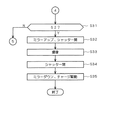
FIGS. 10 to 13 are flowcharts illustrating the shooting operation flow in the
図14及び図15では、横軸が状態S1となってからの時間経過を示している。そして、図14では、上から順に、モータM1のモータ回転数、モータM1に入力されるパルス数(PI数)、フォーカスレンズ2aの移動速度に対応する像面移動速度、AFマイコンの起動、位相差AFの測距、及びC−MOS5の駆動のタイミングが示されている。更に、図14の下方には、コントラストAF制御においてAF評価値を求めるためのC−MOS5における露光タイミング、及びフォーカスレンズ2aの位置とAF評価値との関係が示されている。
In FIG.14 and FIG.15, time passage after the horizontal axis will be in state S1 is shown. 14, in order from the top, the motor rotation number of the motor M1, the number of pulses (PI number) input to the motor M1, the image plane movement speed corresponding to the movement speed of the
また、図15では、フォーカスレンズ2aの位置(すなわち移動)を示す折れ線LL、及びC−MOS5の撮像面(すなわち第2合焦面)の位置(すなわち移動)を示す折れ線LSが示されている。なお、図15の縦軸方向については、折れ線LLの位置に対応した数値は省略されているが、折れ線LSの位置に対応した数値(500μm等)が付されている。更に、図15では、折れ線LLに対して、AF評価値を求めるための露光タイミングに対応するレンズ位置を示すマーク(短い縦長の線分)が付されているとともに、図11の処理ステップに対応する部分にステップ番号(例えば、ステップS14等)が付されている。
In FIG. 15, a broken line LL indicating the position (that is, movement) of the
以下、図14及び図15を適宜参照しつつ、撮影動作フローについて説明する。なお、この撮影動作フローが開始される際には、C−MOS5が実際に本撮影動作を行う所定の基準位置(「撮像ホーム位置」とも称する)に設定され、第1及び第2合焦面の光学的な距離が同一に設定されている。
Hereinafter, the photographing operation flow will be described with reference to FIGS. 14 and 15 as appropriate. When the shooting operation flow is started, the C-
まず、シャッターボタンが半押しされてS1状態となると、撮影動作フローが開始されて、図10のステップS1に進む。 First, when the shutter button is half-pressed to enter the S1 state, the shooting operation flow is started, and the process proceeds to step S1 in FIG.
ステップS1では、C−MOS5が起動する(図14の0〜10ms)。ここでは、C−MOS5に通電し、制御部101からの信号に応じてタイミング制御回路170が制御信号を出力することで、C−MOS5が200fpsの電荷信号の読み出しを開始する。なお、撮像装置1では、光学ファインダーによって被写体を確認することができるため、省電力化のために、S1状態となるとC−MOS5が起動する。
In step S1, the C-
ステップS2では、コントラストAF制御を行うために、シャッター機構4が開放される。なお、S1状態となる前、すなわち待機状態では、シャッター機構4が閉じられた状態にある。
In step S2, the
このステップS1〜S2の処理中に、AFマイコンすなわち制御部101の機能としてのコントラストAF制御部105、位相差AF制御部106、及びAF全体制御部107が起動する(図14の0〜50ms)。
During the processing of steps S1 and S2, the contrast
ステップS3では、位相差AFモジュール3及び位相差AF制御部106によって位相差AF制御による測距を行う(図14の50〜100ms)。
In step S3, the phase
ステップS4では、AF全体制御部107により、ステップS3における測距の結果に基づいて、現在のフォーカスレンズ2aの位置とレンズ合焦位置とのズレ量を判定する。ここで、ズレ量の絶対値が第1の所定値(例えば、30μm)未満である場合には、既に被写体の合焦状態が実現されていると判断し、図11のステップS18に進む。つまり、AF制御を実施することなく、本撮影動作に移行する。また、ズレ量の絶対値が第2の所定値(例えば、1000μm)以上の場合には、ズレ量が十分であるとして、そのまま図11のステップS11に進む。更に、ズレ量の絶対値が第1の所定値以上、第2の所定値未満である場合には、ズレ量が不十分であるとして、ステップS5に進む。
In step S4, the overall
ステップS5では、AF全体制御部107の制御下で、フォーカス制御部130からの制御信号に基づいてモータM1が駆動することで、フォーカスレンズ2aが退避駆動を行う。ここでは、ズレ量が不十分であると、後述する第2合焦面の移動によってコントラストAF制御におけるAF評価値のピークを過ぎてしまう、といった不具合を防ぐために、十分なズレ量を確保するようにフォーカスレンズ2aのレンズ位置を移動させる退避駆動を行う。なお、この退避駆動では、例えば、フォーカスレンズ2aの移動可能な範囲の一端までフォーカスレンズ2aを移動させる。
In step S5, the
ステップS11では、ステップS3における測距の結果に基づいて、C−MOS5を遠側(繰り出し側)又は近側(繰り入れ側)に移動させる動作を開始する(図14の90ms)。ここでは、位相差AFモジュール3による検出結果である測距値に応じて、撮像装置1を基準として、現在のフォーカス位置(ピントが合っている場所)よりも被写体が遠側にあれば、C−MOS5を被写体に近づける方向に移動させる。一方、現在のフォーカス位置(ピントが合っている場所)よりも被写体が近側にあれば、C−MOS5を被写体から遠ざける方向に移動させる。なお、C−MOS5の移動は、例えば、20〜30mm/sec程度の速度で行われる。
In step S11, based on the result of distance measurement in step S3, an operation of moving the C-
ステップS12では、ステップS11において開始されたC−MOS5の移動が終了したか否か判定する。ここでは、所定距離(例えば、500μm)だけC−MOS5が移動するまでステップS12の判定を繰り返し、所定距離だけC−MOS5が移動するとC−MOS5の移動を終了させる(図14及び図15の90〜100ms)。
In step S12, it is determined whether or not the movement of the C-
なお、所定距離は、撮像装置1の光学的な設計によって適宜設定される。また、撮影レンズユニット2のレンズ焦点距離(レンズ焦点距離が長い方が所定距離は長い)や、フォーカスレンズ2aの移動比(フォーカスモーターM1の回転数に対してフォーカスレンズ2aの移動量が長い場合は、所定距離は長い)によって適宜設定される。
Note that the predetermined distance is appropriately set depending on the optical design of the
このように、ステップS11〜S12においては、第1合焦面に対して第2合焦面の光学的な位置が相対的に異なる位置に移動される。具体的には、位相差AFモジュール3による検出結果に応じて、第1及び第2合焦面の光学的な位置が同一に設定されている状態から、フォーカスレンズ2aの位置を移動させつつAF制御を行う際に第1合焦面よりも早期に第2合焦面において被写体の合焦状態が実現される状態に変更される。つまり、位相差AF制御による合焦点到達よりも先にコントラストAF制御によって被写体の合焦状態が検出されるように設定される。
Thus, in steps S11 to S12, the optical position of the second focusing surface is moved to a position that is relatively different from that of the first focusing surface. Specifically, according to the detection result by the phase
ステップS13では、モータM1を立ち上げ、フォーカスレンズ2aの移動を開始する(図14の100〜130ms)。このフォーカスレンズ2aの移動は、位相差AF制御に従ったものである。
In step S13, the motor M1 is started and the movement of the
ステップS14では、AF全体制御部107の制御下で、コントラストAF制御を開始し、200fpsのタイミングでAF評価値を取得する動作を開始する(図14及び図15の145ms)。ここでは、像面移動速度が110μm/10msとある程度遅くなった時点で、AF評価値を取得する動作を行う。なお、このコントラストAF制御は、例えば、絞りを開放状態として実行される。
In step S14, contrast AF control is started under the control of the AF
ステップS15では、レンズ合焦位置を検出する。具体的には、ステップS15に進むと、図12のステップS151に進み、図12に示すレンズ合焦位置の検出動作を実行する(図14及び図15の145〜200ms)。 In step S15, the lens focusing position is detected. Specifically, when the process proceeds to step S15, the process proceeds to step S151 in FIG. 12, and the lens focus position detection operation shown in FIG. 12 is executed (145 to 200 ms in FIGS. 14 and 15).
ここで、図12に示すレンズ合焦位置の検出動作について説明する。 Here, the detection operation of the lens in-focus position shown in FIG. 12 will be described.
図20で示したように、撮影レンズによっては、画像データから抽出される周波数帯域毎におけるMTFのピーク特性が異なるために、周波数帯域毎におけるAF評価値のピークがずれてしまうことがある。このような場合に、幅広い高周波帯域の成分を抽出するHPF601を用いると、周波数帯域毎におけるMTFのずれに起因して、HPF601を用いて取得されたAF評価値のピークが鮮鋭なものとならず、フォーカスレンズ2aのレンズ合焦位置が検出し難くなる。
As shown in FIG. 20, depending on the photographing lens, the peak characteristic of the AF evaluation value for each frequency band may shift because the MTF peak characteristics for each frequency band extracted from the image data are different. In such a case, when the
このような問題に対して、周波数帯域毎のMTFにずれがあったとしても、狭い周波数帯域の高周波成分を重視してAF評価値を求めると、AF評価値が鮮鋭なピークを示すようになる。よって、特定の周波数帯域の成分を抽出するバンドパスフィルタ(BPF)を用いてAF評価値を算出し、AF評価値のピークに対応するレンズ合焦位置を求めることが考えられる。 For such a problem, even if there is a deviation in the MTF for each frequency band, if the AF evaluation value is obtained with emphasis on the high frequency component in a narrow frequency band, the AF evaluation value shows a sharp peak. . Therefore, it is conceivable that an AF evaluation value is calculated using a bandpass filter (BPF) that extracts a component in a specific frequency band, and a lens focus position corresponding to the peak of the AF evaluation value is obtained.
しかしながら、BPFを用いてAF評価値を算出すると、BPFが重視して抽出する特定の周波数帯域と、画像データに多く含まれる高周波成分の帯域とが少しずれると、AF評価値のピークを検出することができない。 However, if the AF evaluation value is calculated using the BPF, the peak of the AF evaluation value is detected if the specific frequency band extracted by the BPF is deviated slightly from the high frequency component band included in the image data. I can't.
そこで、撮像装置1におけるレンズ合焦位置の検出動作では、まず、素直に、幅広い高周波帯域の成分を抽出するHPF601を用いて求めたAF評価値について、AF評価値のピークを検出することができれば、このAF評価値のピークに対応するレンズ位置をレンズ合焦位置として検出する。また、HPF601を用いて求めたAF評価値についてピークを検出することができなければ、より高い周波数成分が多くなれば被写体画像が鮮鋭であると感じる人間の視覚特性に合わせて、相対的に高い周波数成分を重視したBPFから順に採用して得られたAF評価値のピーク検出を行い、このAF評価値のピークに対応するレンズ位置をレンズ合焦位置として検出する。
Therefore, in the detection operation of the lens in-focus position in the
つまり、撮像装置1におけるレンズ合焦位置の検出動作では、4つのフィルタ601〜604のうち、HPF601を用いて求めたAF評価値のピーク検出に対応したレンズ合焦位置の検出を最優先とし、その次に、BPF(0.4fn)602を用いて求めたAF評価値のピーク検出に対応したレンズ合焦位置の検出を優先し、また、その次に、BPF(0.3fn)603を用いて求めたAF評価値のピーク検出に対応したレンズ合焦位置の検出を優先する。そして、最後に、相対的に最も低い周波数成分を重視したBPF(0.1fn)604を用いて求めたAF評価値についてピーク検出を行い、ピークを検出することができれば、このピークに対応したレンズ合焦位置を検出する。
That is, in the detection operation of the lens focus position in the
なお、被写体のコントラストが極めて低い場合には、上記4つのフィルタ601〜604を用いたコントラストAF制御では、レンズ合焦位置を検出することができない場合もある。このような場合には、撮像装置1では、位相差AF制御によって求まるレンズ合焦位置を採用する。
When the contrast of the subject is extremely low, the lens in-focus position may not be detected by contrast AF control using the four
以下、図12に示すレンズ合焦位置の検出動作について具体的に説明する。 Hereinafter, the detection operation of the lens in-focus position shown in FIG. 12 will be specifically described.
ステップS151では、C−MOS5における画像データの取得速度(フレームレート)に相当する200fpsのタイミング毎の垂直同期信号(VDパルス)が立ち下がったか否か判定する。ここでは、VDパルスが立ち下がるまでステップS151の判定を繰り返し、VDパルスが立ち下がればステップS152に進む。
In step S151, it is determined whether or not the vertical synchronization signal (VD pulse) at every 200 fps timing corresponding to the image data acquisition speed (frame rate) in the C-
ステップS152では、コントラストAF制御部105が、HPF601を用いて求められたAF評価値を取得、すなわちHPF601に係るAF評価値を取得する。つまり、VDパルスの立ち下がりに同期してHPF601に係るAF評価値を取得する。
In step S152, the contrast
ステップS153では、HPF601に係るAF評価値(すなわちAF評価値群)についてAF評価値のピークが見つかったか否か判定する。ここで、AF評価値のピークが見つかればステップS164に進み、AF評価値のピークが見つかっていなければステップS154に進む。なお、図14及び図15では、一例としてAF評価値のピークが見つかる場合について示している。
In step S153, it is determined whether or not a peak of the AF evaluation value is found for the AF evaluation value (that is, the AF evaluation value group) related to the
ステップS154では、コントラストAF制御部105が、BPF(0.4fn)602を用いて求められたAF評価値を取得、すなわちBPF(0.4fn)602に係るAF評価値を取得する。
In step S154, the contrast
ステップS155では、BPF(0.4fn)602に係るAF評価値(すなわちAF評価値群)についてAF評価値のピークが見つかったか否か判定する。ここで、AF評価値のピークが見つかればステップS156に進み、AF評価値のピークが見つかっていなければステップS157に進む。 In step S155, it is determined whether or not a peak of the AF evaluation value is found for the AF evaluation value (that is, AF evaluation value group) related to BPF (0.4fn) 602. If an AF evaluation value peak is found, the process proceeds to step S156. If no AF evaluation value peak is found, the process proceeds to step S157.
ステップS156では、BPF(0.4fn)602に係るAF評価値のピークを検出してから、3フレーム分の画像データを取得したか否か判定する。つまり、BPF(0.4fn)602に係るAF評価値のピークを検出した後に、VDパルスが3回立ち下がってC−MOS5において3フレーム分の画像データが取得されたか否か判定する。ここでは、BPF(0.4fn)602に係るAF評価値のピークを検出してから、3フレーム分の画像データが取得されていなければ、ステップS163進み、3フレーム分の画像データが取得されていれば、ステップS164に進む。
In step S156, after detecting the peak of the AF evaluation value related to BPF (0.4fn) 602, it is determined whether or not three frames of image data have been acquired. That is, after detecting the peak of the AF evaluation value related to BPF (0.4fn) 602, it is determined whether or not the VD pulse falls three times and image data for three frames is acquired in the C-
ここで、3フレーム分の画像データを取得したか否か判定するのは、図20で示したMTFの周波数依存性に起因して、周波数帯域毎におけるAF評価値のピークがずれてしまうことがあるため、BPF(0.4fn)602に係るAF評価値のピークを検出してから、フォーカスレンズ2aの位置を若干移動させている間に、BPF(0.4fn)602に係るAF評価値よりも優先的に使用されるHPF601に係るAF評価値についてピークが検出される可能性があるからである。つまり、3フレーム分の画像データを取得したか否か判定するのは、MTFの周波数依存性を考慮して、BPF(0.4fn)602よりも高い周波数帯域を重視したHPF601に係るAF評価値にピークが検出されるか否か待機するためである。
Here, it is determined whether the image data for three frames has been acquired or not because of the frequency dependency of the MTF shown in FIG. Therefore, after detecting the peak of the AF evaluation value related to BPF (0.4 fn) 602, the AF evaluation value related to BPF (0.4 fn) 602 is detected while the position of the
そして、撮像装置1では、フォーカスレンズ2aの位置を移動させて所定距離だけ像面位置を移動させる期間として、3フレーム分の画像データを取得する期間を採用し、その期間、より高い周波数帯域まで重視したHPF601を用いて求められたAF評価値についてピークが検出されれば、HPF601を用いて求められたAF評価値(すなわちAF評価値群)に基づいてレンズ合焦位置を検出するように制御するようにしている。
The
ステップS157では、コントラストAF制御部105が、BPF(0.3fn)603を用いて求められたAF評価値を取得、すなわちBPF(0.3fn)603に係るAF評価値を取得する。
In step S157, the contrast
ステップS158では、BPF(0.3fn)603に係るAF評価値(すなわちAF評価値群)についてAF評価値のピークが見つかったか否か判定する。ここで、AF評価値のピークが見つかればステップS159に進み、AF評価値のピークが見つかっていなければステップS160に進む。 In step S158, it is determined whether or not an AF evaluation value peak has been found for the AF evaluation value (that is, AF evaluation value group) related to BPF (0.3fn) 603. If an AF evaluation value peak is found, the process proceeds to step S159. If no AF evaluation value peak is found, the process proceeds to step S160.
ステップS159では、BPF(0.3fn)603に係るAF評価値のピークを検出してから、3フレーム分の画像データを取得したか否か判定する。ここでは、BPF(0.3fn)603に係るAF評価値のピークを検出してから、3フレーム分の画像データが取得されていなければ、ステップS163進み、3フレーム分の画像データが取得されれていれば、ステップS164に進む。 In step S159, it is determined whether or not three frames of image data have been acquired after the peak of the AF evaluation value related to BPF (0.3fn) 603 has been detected. Here, if the image data for three frames has not been acquired since the peak of the AF evaluation value related to BPF (0.3 fn) 603 has been detected, the process proceeds to step S163, and the image data for three frames has been acquired. If so, the process proceeds to step S164.
なお、ここで、3フレーム分の画像データを取得したか否か判定するのは、ステップS156と同様に、MTFの周波数依存性を考慮して、BPF(0.3fn)603よりも高い周波数帯域を重視したHPF601及びBPF(0.4fn)602を用いて求められたAF評価値についてピークが検出されるか否か待機するためである。
Here, it is determined whether or not image data for three frames has been acquired in the frequency band higher than BPF (0.3 fn) 603 in consideration of the frequency dependence of MTF, as in step S156. This is to wait for whether or not a peak is detected for the AF evaluation value obtained using the
そして、この待機中に、BPF(0.3fn)603よりもより高い周波数帯域を重視した周波数特性を有するHPF601、及びBPF(0.4fn)602の何れかを用いて求められたAF評価値にピークが検出されれば、当該ピークが検出されたAF評価値(すなわちAF評価値群)に基づいてレンズ合焦位置を検出するように制御する。
During this standby, the AF evaluation value obtained using either the
ステップS160では、コントラストAF制御部105が、BPF(0.1fn)604を用いて求められたAF評価値を取得、すなわちBPF(0.1fn)604に係るAF評価値を取得する。
In step S160, the contrast
ステップS161では、BPF(0.1fn)604に係るAF評価値(すなわちAF評価値群)についてAF評価値のピークが見つかったか否か判定する。ここで、AF評価値のピークが見つかればステップS162に進み、AF評価値のピークが見つかっていなければステップS163に進む。 In step S161, it is determined whether or not a peak of the AF evaluation value is found for the AF evaluation value (that is, AF evaluation value group) related to BPF (0.1fn) 604. If an AF evaluation value peak is found, the process proceeds to step S162. If no AF evaluation value peak is found, the process proceeds to step S163.
ステップS162では、BPF(0.1fn)604に係るAF評価値のピークを検出してから、3フレーム分の画像データを取得したか否か判定する。ここでは、BPF(0.1fn)604に係るAF評価値のピークを検出してから、3フレーム分の画像データが取得されていなければ、ステップS163進み、3フレーム分の画像データが取得されれていれば、ステップS164に進む。 In step S162, it is determined whether or not three frames of image data have been acquired after detecting the peak of the AF evaluation value related to BPF (0.1fn) 604. Here, if the image data for three frames has not been acquired since the peak of the AF evaluation value related to BPF (0.1 fn) 604 has been detected, the process proceeds to step S163, and the image data for three frames is acquired. If so, the process proceeds to step S164.
なお、ここで、3フレーム分の画像データを取得したか否か判定するのは、ステップS156,S159と同様に、MTFの周波数依存性を考慮して、BPF(0.1fn)604よりも高い周波数帯域を重視したHPF601、BPF(0.4fn)602、及びBPF(0.3fn)603を用いて求められたAF評価値にピークが検出されるか否か待機するためである。
Here, it is determined whether or not image data for three frames has been acquired, as in steps S156 and S159, in consideration of the frequency dependence of MTF, which is higher than BPF (0.1 fn) 604. This is to wait for whether or not a peak is detected in the AF evaluation values obtained using the
そして、この待機中に、BPF(0.1fn)604よりも高い周波数帯域を重視した周波数特性を有するHPF601、BPF(0.4fn)602、及びBPF(0.3fn)603を用いて求められたAF評価値にピークが検出されれば、当該ピークが検出されたAF評価値(すなわちAF評価値群)に基づいてレンズ合焦位置を検出するように制御する。
Then, during this standby, it was obtained using
ステップS163では、位相差AF制御が終了したか否かを判定する。ここで、位相差AF制御が終了していなければ、ステップS151に戻り、位相差AF制御が終了していれば、C−MOS5が撮像ホーム位置へ戻り(ステップS165)、図11のステップS18に進む。なお、ここでは、位相差AF制御の終了とともに、フォーカスレンズ2aの移動も停止する。
In step S163, it is determined whether or not the phase difference AF control is finished. Here, if the phase difference AF control has not ended, the process returns to step S151. If the phase difference AF control has ended, the C-
ステップS164では、AF評価値に基づいてレンズ合焦位置を検出する。ここでは、ステップS153から進んで来た場合には、HPF601に係るAF評価値(すなわちAF評価値群)に基づいてレンズ合焦位置を検出する。ステップS156から進んで来た場合には、BPF(0.4fn)602に係るAF評価値(すなわちAF評価値群)に基づいてレンズ合焦位置を検出する。ステップS159から進んで来た場合には、BPF(0.3fn)603に係るAF評価値(すなわちAF評価値群)に基づいてレンズ合焦位置を検出する。ステップS162から進んで来た場合には、BPF(0.1fn)604に係るAF評価値(すなわちAF評価値群)に基づいてレンズ合焦位置を検出する。
In step S164, the lens focus position is detected based on the AF evaluation value. Here, when the process proceeds from step S153, the lens in-focus position is detected based on the AF evaluation value (that is, the AF evaluation value group) related to the
ここで、AF評価値(すなわちAF評価値群)に基づいてレンズ合焦位置を検出する手法について説明する。 Here, a method of detecting the lens in-focus position based on the AF evaluation value (that is, the AF evaluation value group) will be described.
ここでは、まず、図14に示すように、AF評価値が増加後、減少し始めたら、AF評価値の最大値Ynとその前後のAF評価値Yn−1、Yn+1の3点のデータを用いて、下式(1)に示す2次補間近似計算によりAF評価値がピークとなるフォーカスレンズ2aのレンズ合焦位置Pを算出する。
Here, first, as shown in FIG. 14, when the AF evaluation value starts to increase and then decreases, three points of data, the maximum AF evaluation value Yn and the AF evaluation values Yn−1 and Yn + 1 before and after that, are used. Thus, the lens focus position P of the

なお、このような計算によってレンズ合焦位置Pが算出されるタイミングは、C−MOS5からの電荷信号の読み出し、AF評価値の算出、AF評価値のピークの検出、及び上式(1)に沿った計算等にある程度時間を要するため、図14に示すように、AF評価値の最大値Ynに係る露光タイミングを過ぎて、AF評価値が連続して4回減少する電荷信号が得られる露光タイミングとなる。
Note that the timing at which the lens in-focus position P is calculated by such calculation is read out of the charge signal from the C-
上記のようにして求められたレンズ合焦位置Pは、C−MOS5を所定距離だけずらした、すなわち所定距離だけずれた撮像面に対するレンズ合焦位置である。このため、レンズ合焦位置Pに所定距離(例えば500μm)の像面差を考慮した値を、実際に本撮影動作を行う撮像ホーム位置に対するレンズ合焦位置Qとして求める。
The lens in-focus position P obtained as described above is a lens in-focus position with respect to the imaging surface in which the C-
このようにして、位相差AF制御によるフォーカスレンズ2aの移動が終了する前に、レンズ合焦位置Qを求めることができる。
In this way, the lens focus position Q can be obtained before the movement of the
そして、ステップS164の処理が終了すると、図11のステップS16に進む。 Then, when the process of step S164 ends, the process proceeds to step S16 of FIG.
ステップS16では、C−MOS5が撮像ホーム位置へ戻るように移動する(図14及び図15の210〜220ms)。
In step S16, the C-
ステップS17では、レンズ合焦位置Qでフォーカスレンズ2aの移動を停止する(図14及び図15の235ms)。
In step S17, the movement of the
ステップS18では、シャッター機構4を閉じる。
In step S18, the
ステップS19では、C−MOS5に蓄積された電荷を排出することでリセットする。
In step S19, the charge is reset by discharging the charge accumulated in the C-
ステップS20では、S1状態が解除されたか否か判定する。ここでは、例えば、ユーザーが操作部OPを操作することでS1状態が解除されると、本動作フローを終了し、S1状態が解除されなければ、図13のステップS31に進む。 In step S20, it is determined whether the S1 state has been released. Here, for example, when the S1 state is canceled by the user operating the operation unit OP, the operation flow is terminated. If the S1 state is not canceled, the process proceeds to step S31 in FIG.
ステップS31では、S2状態になったか否かを判定する。ここでは、S2状態となるまで、ステップS21及びステップS31の判定を繰り返しつつ、待機する。そして、S
2状態となると、本撮影動作の指示がなされたものとして、ステップS32に進む。
In step S31, it is determined whether or not the S2 state has been reached. Here, it waits, repeating determination of step S21 and step S31 until it will be in S2 state. And S
In the second state, it is determined that an instruction for the main photographing operation has been given, and the process proceeds to step S32.
ステップS32では、主ミラー10及びサブミラー20がミラーアップ状態となるとともに、シャッター機構4が開かれた状態となる。
In step S32, the
ステップS33では、C−MOS5において、撮像すなわち本撮影動作の露光が行われる。
In step S33, the C-
ステップS34では、シャッター機構4が閉じられた状態となる。
In step S34, the
ステップS35では、主ミラー10及びサブミラー20がミラーダウン状態となるとともに、C−MOS5から電荷信号が読み出されて、画像データがメモリカードMCに記憶されるチャージ駆動を行い、本動作フローを終了する。
In step S35, the
以上のように、本発明の実施形態に係る撮像装置1では、AF回路600に備えられた4つ(一般的には複数)のフィルタ601〜604のうちのHPF601を用いて取得されたAF評価値を最優先に使用して、フォーカスレンズ2aのレンズ合焦位置を検出する。このように、一般的な被写体を撮影する際に画像データにおいて増加する高周波帯域の成分を重視して抽出するHPF601が優先的に使用されるように設定されているため、種々の被写体に対して高精度の合焦制御を行うことができる。
As described above, in the
また、4つ(一般的には複数)のフィルタ601〜604のうちの相対的に高い周波数帯域の成分を重視して抽出する周波数特性を有する所定のフィルタ(ここでは、HPF601)を用いて取得されたAF評価値を優先的に使用して、フォーカスレンズ2aのレンズ合焦位置を検出する。このような構成を採用することで、例えば、より高い周波数成分が多くなれば被写体画像が鮮鋭であると感じる人間の視覚特性に対応した合焦制御が可能となるため、高精度の合焦制御ができる。
Moreover, it acquires using the predetermined filter (here HPF601) which has the frequency characteristic which attaches importance and extracts the component of a relatively high frequency band among the four (generally plural) filters 601 to 604. The focused AF evaluation value is preferentially used to detect the focus position of the
また、被写体からの光を2つの光路に分割して、分割された各光を用いて位相差方式の合焦制御とコントラスト方式の合焦制御とを並行して実施する。このため、例えば、位相差方式の合焦制御によってフォーカスレンズ2aをレンズ合焦位置近傍まで短時間で駆動させることができるとともに、コントラスト方式の合焦制御によって合焦制御の精度を確保することができる。その結果、高速かつ精度の良い合焦制御が可能となる。
Further, the light from the subject is divided into two optical paths, and the phase difference type focusing control and the contrast type focusing control are performed in parallel using each of the divided lights. For this reason, for example, the
また、位相差方式及びコントラスト方式の合焦検出に係る合焦面の光学的な位置を相互に異ならせ、位相差方式の合焦制御の開始後に、コントラスト方式の合焦制御が開始される。このような構成により、同時に2つの方式の合焦制御が行われ、位相差方式の合焦制御による合焦状態の実現前に、コントラスト方式の合焦制御によってフォーカスレンズ2aのレンズ合焦位置を検出することができる。その結果、高速かつ高精度の合焦制御を実現することができる。また、例えば、フォーカスレンズ2aを逆向きに移動させることなく合焦制御を行うことができるため、いわゆるバックラッシュの問題の発生も防止することができる。更に、例えば、ファインダ等を介して視認される被写体が、ぼけた状態から合焦状態へとスムーズに変化するような合焦制御を行うことができるため、合焦フィーリングを向上させることもできる。
Further, the optical positions of the in-focus surfaces for the phase difference method and the contrast method focus detection are made different from each other, and the contrast method focus control is started after the phase difference method focus control is started. With such a configuration, two types of focusing control are performed at the same time, and the focus position of the
<変形例>
以上、この発明の実施形態について説明したが、この発明は上記説明した内容のものに限定されるものではない。
<Modification>
As mentioned above, although embodiment of this invention was described, this invention is not limited to the thing of the content demonstrated above.
◎例えば、上述した実施形態では、BPF(0.4fn)602、BPF(0.3fn)603、及びBPF(0.1fn)604の3つの異なる周波数特性を有するバンドパスフィルタを採用したが、これに限られない。例えば、0.5fnや0.2fn付近の周波数帯域の成分を主に抽出(透過)するバンドパスフィルタを等を採用しても良い。すなわち、fnのn倍(0<n<1)付近の周波数帯域の成分を主に抽出(透過)する1以上のバンドパスフィルタを採用しても良い。 For example, in the above-described embodiment, band pass filters having three different frequency characteristics of BPF (0.4 fn) 602, BPF (0.3 fn) 603, and BPF (0.1 fn) 604 are employed. Not limited to. For example, a band pass filter that mainly extracts (transmits) components in a frequency band near 0.5 fn or 0.2 fn may be employed. That is, one or more band-pass filters that mainly extract (transmit) a frequency band component near n times fn (0 <n <1) may be employed.
なお、撮影レンズユニット2が撮像装置本体300に対して着脱自在に構成される態様では、複数の異なる周波数特性を有するバンドパスフィルタを準備しておき、撮像装置本体300に対して撮影レンズユニット2が装着されると、制御部101が撮影レンズユニット2内のROM等からレンズの特性を特定する情報(レンズ情報)を得て、1以上のバンドパスフィルタをコントラストAF制御に用いるバンドパスフィルタとして選択的に採用しても良い。例えば、0.1fn、0.2fn、0.3fn、0.4fn、及び0.5fn付近の周波数帯域の成分を主に抽出(透過)する5つのバンドパスフィルタを準備しておき、レンズ情報に応じて、0.1fn、0.3fn、及び0.4fn付近の周波数帯域の成分を主に抽出(透過)する3つのバンドパスフィルタをコントラストAF制御に用いるバンドパスフィルタとして選択的に採用するようにしても良い。
In an aspect in which the photographing
◎また、上記実施形態では、図8で示したHPF601、BPF(0.4fn)602、BPF(0.3fn)603、及びBPF(0.1fn)604の4つの異なる周波数特性を有するフィルタを採用したが、これに限られない。 In the above embodiment, the filters having four different frequency characteristics, HPF601, BPF (0.4fn) 602, BPF (0.3fn) 603, and BPF (0.1fn) 604 shown in FIG. 8, are employed. However, it is not limited to this.
例えば、図16で示す2つの異なる周波数特性を有するハイパスフィルタを採用しても良い。図16で示す曲線F1は、図8で示したHPF601の周波数特性を示している。また、曲線F2は、HPF601と比較して、一般的な撮影において輪郭が明確な被写体の増加に応じて画像データの周波数成分が増加する所定の周波数帯域(例えば、0.2fn〜0.4fn)付近の高周波成分をより重視して抽出するHPFの周波数特性を示している。なお、以下では、曲線F1の周波数特性を有するHPFをHPF1、曲線F11の周波数特性を有するHPFをHPF2と称する。
For example, a high-pass filter having two different frequency characteristics shown in FIG. 16 may be employed. A curve F1 shown in FIG. 16 shows the frequency characteristics of the
HPF2では、HPF1と比較して、1.0fn付近の高周波帯域に対するゲインが小さくなっているため、画像データにおける所謂ノイズ成分の抽出(透過)を防ぐことができる。また、上述したように、一般的な撮影において輪郭が明確な被写体の増加に応じて画像データの周波数成分が増加する所定の周波数帯域付近の高周波成分をより重視して抽出する。このため、HPF1と比較して、HPF2を用いて取得されるAF評価値を用いた方が、ノイズ成分の影響を低減しつつ、被写体に対してより精度良く合焦させることができる。 Since HPF2 has a smaller gain for a high frequency band near 1.0 fn than HPF1, so-called noise component extraction (transmission) in image data can be prevented. Further, as described above, high-frequency components in the vicinity of a predetermined frequency band in which the frequency components of image data increase in accordance with an increase in subjects with clear outlines in general photographing are extracted with more importance. For this reason, compared with HPF1, using the AF evaluation value acquired using HPF2 can focus on the subject more accurately while reducing the influence of the noise component.
したがって、HPF1,2を用いる場合には、合焦精度の観点から、2つのHPFのうちのHPF1よりも相対的に所定の周波数帯域(ここでは、0.2fn〜0.4fn)の成分を重視して抽出する周波数特性を有する所定のHPF2を用いて取得されたAF評価値(すなわち、AF評価値群)を優先的に使用して、フォーカスレンズ2aのレンズ合焦位置を検出することが好ましい。
Therefore, when using
以下、撮像装置においてHPF1,2を用いたコントラストAF制御を採用した場合における撮影動作フローについて説明する。なお、この撮影動作フローでは、図10〜図13で示した撮影動作フローのうち、ステップS15のレンズ合焦位置の検出動作に係るフローが異なるが、他の動作については同様なものとなる。つまり、図12で示したレンズ合焦位置の検出動作フローが異なる。
Hereinafter, an imaging operation flow when the contrast AF
図17は、HPF1,2を用いた場合におけるレンズ合焦位置の検出動作フローを示している。 FIG. 17 shows a detection operation flow of the lens in-focus position when HPFs 1 and 2 are used.
ステップST151では、C−MOS5における画像データの取得速度(フレームレート)に相当する200fpsのタイミング毎の垂直同期信号(VDパルス)が立ち下がったか否か判定する。ここでは、VDパルスが立ち下がるまでステップS151の判定を繰り返し、VDパルスが立ち下がればステップST152に進む。
In step ST151, it is determined whether a vertical synchronization signal (VD pulse) at every 200 fps timing corresponding to the image data acquisition speed (frame rate) in the C-
ステップST152では、コントラストAF制御部105が、HPF2を用いて求められたAF評価値を取得、すなわちHPF2に係るAF評価値を取得する。つまり、VDパルスの立ち下がりに同期してHPF2に係るAF評価値を取得する。
In step ST152, the contrast
ステップST153では、HPF2に係るAF評価値(すなわちAF評価値群)についてAF評価値のピークが見つかったか否か判定する。ここで、AF評価値のピークが見つかればステップST158に進み、AF評価値のピークが見つかっていなければステップST154に進む。 In step ST153, it is determined whether or not a peak of the AF evaluation value is found for the AF evaluation value (that is, the AF evaluation value group) related to HPF2. If an AF evaluation value peak is found, the process proceeds to step ST158. If no AF evaluation value peak is found, the process proceeds to step ST154.
ステップST154では、コントラストAF制御部105が、HPF1を用いて求められたAF評価値を取得、すなわちHPF1に係るAF評価値を取得する。
In step ST154, the contrast
ステップST155では、HPF1に係るAF評価値(すなわちAF評価値群)についてAF評価値のピークが見つかったか否か判定する。ここで、AF評価値のピークが見つかればステップST156に進み、AF評価値のピークが見つかっていなければステップST157に進む。 In step ST155, it is determined whether or not a peak of the AF evaluation value is found for the AF evaluation value (that is, the AF evaluation value group) related to HPF1. If an AF evaluation value peak is found, the process proceeds to step ST156. If no AF evaluation value peak is found, the process proceeds to step ST157.
ステップST156では、HPF1に係るAF評価値のピークを検出してから、3フレーム分の画像データを取得したか否か判定する。つまり、HPF1に係るAF評価値のピークを検出した後に、VDパルスが3回立ち下がってC−MOS5において3フレーム分の画像データが取得されたか否か判定する。ここでは、HPF1に係るAF評価値のピークを検出してから、3フレーム分の画像データが取得されていなければ、ステップST157進み、3フレーム分の画像データが取得されていれば、ステップST158に進む。
In step ST156, after detecting the peak of the AF evaluation value related to HPF1, it is determined whether image data for three frames has been acquired. That is, after detecting the peak of the AF evaluation value related to HPF1, it is determined whether or not three frames of image data have been acquired in the C-
ここで、3フレーム分の画像データを取得したか否か判定するのは、図20で示したMTFの周波数依存性も考慮して、HPF1よりもHPF2を用いて取得されたAF評価値を優先させるためである。 Here, whether or not the image data for three frames has been acquired is determined by giving priority to the AF evaluation value acquired using HPF2 over HPF1 in consideration of the frequency dependence of the MTF shown in FIG. This is to make it happen.
ステップST157では、図12のステップS163と同様な処理を行う。 In step ST157, the same processing as step S163 in FIG. 12 is performed.
ステップST158では、AF評価値(すなわちAF評価値群)に基づいてレンズ合焦位置を検出する。ここでは、ステップST153から進んで来た場合には、HPF2に係るAF評価値に基づいてレンズ合焦位置を検出する。ステップST156から進んで来た場合には、HPF1に係るAF評価値に基づいてレンズ合焦位置を検出する。そして、ステップST158の処理が終了すると、図11のステップS16に進む。 In step ST158, the lens focus position is detected based on the AF evaluation value (that is, the AF evaluation value group). Here, when the process proceeds from step ST153, the lens in-focus position is detected based on the AF evaluation value related to HPF2. When the process proceeds from step ST156, the lens in-focus position is detected based on the AF evaluation value related to HPF1. Then, when the process of step ST158 ends, the process proceeds to step S16 of FIG.
以上のような構成を採用した撮像装置では、AF回路600に備えられた2つ(一般的には複数)のフィルタ(HPF1,2)のうち、一般的な被写体を撮影する際に高まる周波数成分を重視して抽出するHPF2を用いて取得されたAF評価値を最優先に使用して、フォーカスレンズ2aのレンズ合焦位置を検出する。このような構成により、種々の被写体に対して高精度の合焦制御を行うことができる。
In the imaging apparatus employing the above-described configuration, a frequency component that increases when shooting a general subject among the two (generally plural) filters (HPF1, 2) provided in the
また、別の観点から言えば、2つ(一般的には複数)のフィルタ(HPF1,2)のうちのHPF1よりも相対的に所定の周波数帯域(ここでは、0.2fn〜0.4fn)の成分を重視して抽出する周波数特性を有するHPF2を用いて取得されたAF評価値を優先的に使用して、フォーカスレンズ2aのレンズ合焦位置を検出する。このような構成を採用することで、例えば、一般的な被写体を捉えた画像が合焦状態にある場合に増加する所定の高周波帯域の成分を重視した合焦制御が可能となるため、高精度の合焦制御ができる。
From another point of view, a predetermined frequency band (in this case, 0.2 fn to 0.4 fn) relative to HPF1 of two (generally plural) filters (HPF1, 2). The lens focus position of the
なお、上記では、一般的な撮影において輪郭が明確な被写体の増加に応じて画像データの周波数成分が増加する所定の周波数帯域として、0.2fn〜0.4fnの周波数帯域を挙げたが、この所定の周波数帯域は、被写体の種類、撮影レンズユニット2の性質、撮影倍率、及び撮像素子の画素ピッチ等の条件の組合せに応じて適宜設定される。
In the above description, the frequency band of 0.2 fn to 0.4 fn is given as the predetermined frequency band in which the frequency component of the image data increases in accordance with an increase in subjects with clear outlines in general photographing. The predetermined frequency band is appropriately set according to a combination of conditions such as the type of subject, the nature of the photographing
◎また、上記実施形態では、図8で示したBPF(0.4fn)602、BPF(0.3fn)603、及びBPF(0.1fn)604の3つの異なる周波数特性を有するバンドパスフィルタを採用したが、これに限られない。 In the above embodiment, the band-pass filter having three different frequency characteristics of BPF (0.4 fn) 602, BPF (0.3 fn) 603, and BPF (0.1 fn) 604 shown in FIG. 8 is employed. However, it is not limited to this.
例えば、図18の曲線F12,F13で示すように、BPFの代わりに、所謂カットオフ周波数がfco1,fco2である周波数特性をそれぞれ有する2つのHPFを採用し、より高い周波数帯域の成分を重視して抽出するHPFを用いて得られるAF評価値から順に優先的に使用してレンズ合焦位置を検出するようにしても良い。なお、曲線F1,F12,F13で示される周波数特性をそれぞれ有する3つのHPFをそれぞれHPFa,HPFb、HPFcとすると、HPFaが、最も高い周波数帯域の成分を重視して抽出し、HPFbが、次に高い周波数帯域の成分を重視して抽出し、HPFcが、最も低い周波数帯域の成分を重視して抽出する。 For example, as shown by curves F12 and F13 in FIG. 18, two HPFs each having frequency characteristics with so-called cutoff frequencies fco1 and fco2 are employed instead of BPF, and components of higher frequency bands are emphasized. The lens focus position may be detected by using the AF evaluation values obtained using the HPF extracted in this order with priority. If the three HPFs having the frequency characteristics indicated by the curves F1, F12, and F13 are HPFa, HPFb, and HPFc, respectively, the HPFa is extracted with emphasis on the highest frequency band component, and the HPFb is The high frequency band component is extracted with importance, and HPFc extracts the lowest frequency band component with importance.
◎また、上記実施形態では、本撮影時に記録用の画像データを得るためのC−MOS5を用いて得られた画像データに基づきコントラストAF制御を行ったが、これに限られず、例えば、コントラストAF制御のための画像データを取得する専用の撮像センサを設けても良い。
In the above embodiment, the contrast AF control is performed based on the image data obtained by using the C-
◎また、コントラストAF制御のために、例えば、所謂ベイヤー配列を有する複数のRGBの3原色の画素を有する撮像センサが採用された場合、AF評価値を取得する際には、G色の画素値のみを用いてAF評価値を算出するようにしても良いし、RGBの画素値から輝度値Yを算出して、当該輝度値Yを用いてAF評価値を算出するようにしても良い。 For contrast AF control, for example, when an imaging sensor having a plurality of RGB three primary colors having a so-called Bayer array is employed, when obtaining an AF evaluation value, a G pixel value The AF evaluation value may be calculated using only the luminance value, or the luminance value Y may be calculated from the RGB pixel values, and the AF evaluation value may be calculated using the luminance value Y.
◎なお、上記実施形態では、フィルタ601〜604を電気的な回路として構成したが、制御部101においてプログラムを実行することでフィルタ601〜604の機能及びAF評価値の演算機能を実現するようにすることもできる。但し、現状では、一般に電気的な回路で構成した演算機能の方が演算速度が高速であり実用的である。
In the above embodiment, the
◎また、上記実施形態では、図2に示すようなAF制御ユニット100を採用したが、これに限られず、他のAF制御ユニットの構成を採用しても良い。以下に、他のAF制御ユニットの構成の一例としてAF制御ユニット100Aを挙げて説明する。
In the above embodiment, the
図19は、変形例に係る撮像装置1Aに含まれたAF制御ユニット100Aに関する構成を模式的に例示する図である。
FIG. 19 is a diagram schematically illustrating a configuration related to the
上記実施形態に係る撮像装置1では、主ミラー10がハーフミラーを備えて構成されたが、図19に示すように、変形例に係る撮像装置1Aでは、当該ハーフミラーとしてペリクルミラーを採用した主ミラー10Aを用いている。
In the
ペリクルミラーは、厚みが一般的なハーフミラーと比べて非常に薄い(例えば100μm程度)ことが特徴である。このペリクルミラーは、極薄であるため、ミラーアップ駆動に適さない。よって、撮像装置1Aでは、本撮影時に、主ミラー10Aはミラーアップせず、サブミラー20Aが被写体からの光の光路上から下方に退避するように構成されている。
The pellicle mirror is characterized in that it is very thin (for example, about 100 μm) compared to a general half mirror. Since this pellicle mirror is extremely thin, it is not suitable for mirror-up driving. Therefore, the
なお、その他の構成は、上記実施形態に係る撮像装置1と同様であり、機能及び動作等については、主ミラー10及びサブミラー20の双方が光路に対して退避状態/遮断状態となる代わりに、サブミラー20Aのみが光路に対して退避状態/遮断状態となる点が異なるだけで、その他の機能及び動作等についてはほぼ同様であるため、説明を省略する。
Other configurations are the same as those of the
以下、主ミラー10Aのハーフミラーにペリクルミラーを採用する利点について説明する。
Hereinafter, advantages of using a pellicle mirror as the half mirror of the
上記実施形態に係る撮像装置1では、一般的なハーフミラーの屈折率Ndが約1.5であり、主ミラー10とサブミラー20の厚みをそれぞれa、bとすると、ミラーアップ状態とミラーダウン状態とで約0.5(a+b)だけ焦点位置がユーザー側(図2では右側)にずれてしまう。
In the
そして、位相差AF制御とコントラストAF制御とを併用する場合には、フォーカスレンズ2aの位置を移動させつつ被写体の合焦状態を実現する際に第1合焦面よりも早期に第2合焦面において被写体の合焦状態が実現されるように、第1及び第2合焦面の光学的な位置を相互に異ならせる必要がある。よって、このとき、ハーフミラーによる焦点位置のずれ(約0.5(a+b))を見込んで、C−MOS5を撮像ホーム位置から光軸Lに沿って余計に移動させなければならない。
When the phase difference AF control and the contrast AF control are used in combination, the second focusing is performed earlier than the first focusing surface when realizing the in-focus state of the subject while moving the position of the
このような問題点に対して、極薄のペリクルミラーを用いることで、ハーフミラーによる焦点位置のずれを約0.5bまで抑制することができる。つまり、主ミラー10によって生じる焦点位置のズレ量を抑制することができる。その結果、当該ズレ量を補正するためのC−MOS5の移動量が少なくて済むため、C−MOS5を移動させるための構成を簡素化することができる。
With respect to such a problem, by using an extremely thin pellicle mirror, it is possible to suppress the shift of the focal position by the half mirror to about 0.5b. That is, the amount of shift of the focal position caused by the
◎また、上記実施形態では、位相差AF制御を行うタイプの撮像装置を挙げて説明したが、これに限られず、例えば、コントラストAF制御のみを行う撮像装置であっても良い。 In the above-described embodiment, the type of imaging apparatus that performs phase difference AF control has been described. However, the present invention is not limited to this. For example, an imaging apparatus that performs only contrast AF control may be used.
1,1A 撮像装置
2 撮影レンズユニット
2a フォーカスレンズ
3 位相差AFモジュール
5 C−MOS
10,10A 主ミラー
10a ミラー機構
20,20A サブミラー
20a サブミラー機構
100,100A AF制御ユニット
101 制御部
105 コントラストAF制御部
106 位相差AF制御部
107 AF全体制御部
110 ミラー制御部
120 サブミラー制御部
130 フォーカス制御部
140 シャッタ制御部
150 C−MOS移動制御部
170 タイミング制御回路
201 レンズ位置検出部
300 撮像装置本体
500 信号処理回路
600 AF回路
601 ハイパスフィルタ
602〜604 バンドパスフィルタ
611〜614 評価値演算部
DESCRIPTION OF
10,
Claims (7)
光学レンズを光軸に沿って駆動させている間に、当該光学レンズを介して入射される被写体からの光に基づいて複数の画像データを時間順次に取得する画像取得手段と、
前記複数の画像データを相互に周波数特性が異なる複数のフィルタを用いてそれぞれ処理して、前記複数のフィルタを構成するフィルタ毎に評価値群を取得する評価値取得手段と、
前記評価値取得手段において前記複数のフィルタのうちの所定のフィルタを用いた処理によって取得された評価値群を、前記複数のフィルタのうちの前記所定のフィルタとは異なる他のフィルタを用いた処理によって取得された評価値群よりも優先的に用いて、前記光学レンズの合焦位置を検出する合焦検出手段と、
を備えることを特徴とする合焦制御装置。 A focus control device that performs focus control of an imaging device,
An image acquisition unit that sequentially acquires a plurality of image data based on light from a subject incident through the optical lens while driving the optical lens along the optical axis;
Evaluation value acquisition means for processing the plurality of image data using a plurality of filters having different frequency characteristics from each other, and acquiring an evaluation value group for each of the filters constituting the plurality of filters;
Processing using an evaluation value group acquired by processing using a predetermined filter of the plurality of filters in the evaluation value acquisition unit using another filter different from the predetermined filter of the plurality of filters Focus detection means for detecting the focus position of the optical lens using preferentially over the evaluation value group acquired by
An in-focus control device comprising:
前記所定のフィルタが、
前記複数のフィルタのうちの前記所定のフィルタとは異なる他のフィルタよりも相対的に高い周波数帯域の成分を重視して抽出する周波数特性を有することを特徴とする合焦制御装置。 The focusing control device according to claim 1,
The predetermined filter is
An in-focus control device characterized by having a frequency characteristic of extracting a component in a frequency band relatively higher than other filters different from the predetermined filter among the plurality of filters.
前記合焦検出手段が、
前記複数のフィルタのうちの相対的に高い周波数帯域の成分を重視して抽出する周波数特性を有するフィルタによって取得された評価値群を優先的に用いて、前記合焦位置を検出することを特徴とする合焦制御装置。 The focusing control device according to claim 1,
The focus detection means;
The focus position is detected by preferentially using an evaluation value group acquired by a filter having a frequency characteristic extracted with emphasis on components of a relatively high frequency band among the plurality of filters. Focus control device.
前記所定のフィルタが、
前記複数のフィルタのうちの前記所定のフィルタとは異なる他のフィルタよりも相対的に所定の周波数帯域の成分を重視して抽出する周波数特性を有することを特徴とする合焦制御装置。 The focusing control device according to claim 1,
The predetermined filter is
An in-focus control device characterized by having a frequency characteristic of extracting a component of a predetermined frequency band with a greater importance than other filters different from the predetermined filter among the plurality of filters.
位相差方式を用いて前記光学レンズの合焦位置を検出する位相差検出手段と、
前記被写体からの光を、前記合焦検出手段及び前記位相差検出手段に対してそれぞれ導く第1及び第2の光路に分割する光分割手段と、
を更に備え、
前記位相差検出手段を用いた合焦制御と、前記合焦検出手段を用いた合焦制御とが並行して実行されることを特徴とする合焦制御装置。 A focusing control device according to any one of claims 1 to 4,
A phase difference detecting means for detecting a focus position of the optical lens using a phase difference method;
Light splitting means for splitting light from the subject into first and second optical paths that guide the light from the subject to the focus detection means and the phase difference detection means, respectively;
Further comprising
An in-focus control apparatus, wherein the in-focus control using the phase difference detecting means and the in-focus control using the in-focus detection means are executed in parallel.
前記合焦検出手段が、
前記位相差検出手段に係る合焦面とは相対的に異なる光学的な位置に合焦面を有し、
前記合焦制御装置が、
前記位相差検出手段を用いた合焦制御の開始後に、前記合焦検出手段を用いた合焦制御を開始するタイミング制御手段、
を更に備えることを特徴とする合焦制御装置。 The focusing control device according to claim 5,
The focus detection means;
Having a focusing surface at an optical position relatively different from the focusing surface according to the phase difference detection means,
The focusing control device is
Timing control means for starting focus control using the focus detection means after start of focus control using the phase difference detection means;
And a focusing control device.
Priority Applications (7)
| Application Number | Priority Date | Filing Date | Title |
|---|---|---|---|
| JP2006008379A JP2007192859A (en) | 2006-01-17 | 2006-01-17 | Focus control device and imaging device |
| US11/908,324 US20090066830A1 (en) | 2006-01-17 | 2007-01-16 | Focus control device and imaging device |
| PCT/JP2007/050518 WO2007083633A1 (en) | 2006-01-17 | 2007-01-16 | Focus control device and imaging device |
| EP07706845A EP1975662A1 (en) | 2006-01-17 | 2007-01-16 | Focus control device and imaging device |
| KR1020077020651A KR20080084563A (en) | 2006-01-17 | 2007-01-16 | In-focus controller and imaging device |
| CNA2007800000828A CN101310205A (en) | 2006-01-17 | 2007-01-16 | Focusing control device and imaging device |
| TW096101774A TW200739230A (en) | 2006-01-17 | 2007-01-17 | Focus control device and imaging device |
Applications Claiming Priority (1)
| Application Number | Priority Date | Filing Date | Title |
|---|---|---|---|
| JP2006008379A JP2007192859A (en) | 2006-01-17 | 2006-01-17 | Focus control device and imaging device |
Publications (1)
| Publication Number | Publication Date |
|---|---|
| JP2007192859A true JP2007192859A (en) | 2007-08-02 |
Family
ID=38287586
Family Applications (1)
| Application Number | Title | Priority Date | Filing Date |
|---|---|---|---|
| JP2006008379A Abandoned JP2007192859A (en) | 2006-01-17 | 2006-01-17 | Focus control device and imaging device |
Country Status (7)
| Country | Link |
|---|---|
| US (1) | US20090066830A1 (en) |
| EP (1) | EP1975662A1 (en) |
| JP (1) | JP2007192859A (en) |
| KR (1) | KR20080084563A (en) |
| CN (1) | CN101310205A (en) |
| TW (1) | TW200739230A (en) |
| WO (1) | WO2007083633A1 (en) |
Cited By (4)
| Publication number | Priority date | Publication date | Assignee | Title |
|---|---|---|---|---|
| JP2015102840A (en) * | 2013-11-28 | 2015-06-04 | 株式会社ニコン | Focus detection device |
| JP2016014839A (en) * | 2014-07-03 | 2016-01-28 | キヤノン株式会社 | Imaging apparatus and control method thereof |
| JP2016057516A (en) * | 2014-09-11 | 2016-04-21 | キヤノン株式会社 | Control device, imaging device, control method, program and recording medium |
| JP2016061798A (en) * | 2014-09-12 | 2016-04-25 | キヤノン株式会社 | Automatic focusing apparatus and automatic focusing method |
Families Citing this family (11)
| Publication number | Priority date | Publication date | Assignee | Title |
|---|---|---|---|---|
| JP2011138103A (en) * | 2009-12-02 | 2011-07-14 | Ricoh Co Ltd | Imaging apparatus and method |
| KR101085925B1 (en) * | 2010-03-23 | 2011-11-23 | 삼성전자주식회사 | Photographing apparatus for performing auto focus control function using a plurality of band pass filters and auto focus control method applied thereto |
| US10250793B2 (en) | 2011-06-29 | 2019-04-02 | Nikon Corporation | Focus adjustment device having a control unit that drives a focus adjustment optical system to a focused position acquired first by either a contrast detection system or a phase difference detection system |
| EP4310569B1 (en) * | 2011-11-11 | 2026-01-21 | Nikon Corporation | Focal point adjustment device, image capture device, and lens barrel |
| CN104823094B (en) * | 2012-11-29 | 2017-08-11 | 富士胶片株式会社 | Camera device and focusing control method |
| US9477138B2 (en) * | 2013-06-10 | 2016-10-25 | Apple Inc. | Autofocus |
| US10078198B2 (en) | 2014-08-08 | 2018-09-18 | Samsung Electronics Co., Ltd. | Photographing apparatus for automatically determining a focus area and a control method thereof |
| CN105430270B (en) | 2015-12-10 | 2018-11-13 | 浙江宇视科技有限公司 | A kind of method and apparatus focused automatically |
| CN106506946B (en) * | 2016-10-26 | 2019-10-18 | 浙江宇视科技有限公司 | A camera automatic focusing method and camera |
| JP6561370B1 (en) * | 2018-06-19 | 2019-08-21 | エスゼット ディージェイアイ テクノロジー カンパニー リミテッドSz Dji Technology Co.,Ltd | Determination device, imaging device, determination method, and program |
| WO2021217427A1 (en) * | 2020-04-28 | 2021-11-04 | 深圳市大疆创新科技有限公司 | Image processing method and apparatus, photographing device, movable platform, and storage medium |
Family Cites Families (10)
| Publication number | Priority date | Publication date | Assignee | Title |
|---|---|---|---|---|
| JPS59133783A (en) * | 1983-01-20 | 1984-08-01 | Matsushita Electric Ind Co Ltd | automatic focusing device |
| US4484806A (en) * | 1982-04-28 | 1984-11-27 | Matsushita Electric Industrial Co., Ltd. | Automatic focussing apparatus |
| JPS63215171A (en) * | 1987-03-03 | 1988-09-07 | Victor Co Of Japan Ltd | Automatic focusing system |
| JPH05308555A (en) * | 1992-04-28 | 1993-11-19 | Fuji Photo Optical Co Ltd | Method and device for automatic focusing |
| JP4331314B2 (en) * | 1999-04-12 | 2009-09-16 | オリンパス株式会社 | Single-lens reflex type electronic imaging device |
| JP2004219581A (en) * | 2003-01-10 | 2004-08-05 | Canon Inc | Automatic focusing device |
| JP4324402B2 (en) * | 2003-04-08 | 2009-09-02 | Hoya株式会社 | Camera autofocus device |
| JP4374574B2 (en) * | 2004-03-30 | 2009-12-02 | 富士フイルム株式会社 | Manual focus adjustment device and focus assist program |
| JP2005351925A (en) * | 2004-06-08 | 2005-12-22 | Fuji Photo Film Co Ltd | Imaging apparatus and focus control method |
| JP4042748B2 (en) * | 2005-02-09 | 2008-02-06 | 株式会社ニコン | Autofocus device |
-
2006
- 2006-01-17 JP JP2006008379A patent/JP2007192859A/en not_active Abandoned
-
2007
- 2007-01-16 CN CNA2007800000828A patent/CN101310205A/en active Pending
- 2007-01-16 KR KR1020077020651A patent/KR20080084563A/en not_active Withdrawn
- 2007-01-16 EP EP07706845A patent/EP1975662A1/en not_active Withdrawn
- 2007-01-16 US US11/908,324 patent/US20090066830A1/en not_active Abandoned
- 2007-01-16 WO PCT/JP2007/050518 patent/WO2007083633A1/en not_active Ceased
- 2007-01-17 TW TW096101774A patent/TW200739230A/en unknown
Cited By (4)
| Publication number | Priority date | Publication date | Assignee | Title |
|---|---|---|---|---|
| JP2015102840A (en) * | 2013-11-28 | 2015-06-04 | 株式会社ニコン | Focus detection device |
| JP2016014839A (en) * | 2014-07-03 | 2016-01-28 | キヤノン株式会社 | Imaging apparatus and control method thereof |
| JP2016057516A (en) * | 2014-09-11 | 2016-04-21 | キヤノン株式会社 | Control device, imaging device, control method, program and recording medium |
| JP2016061798A (en) * | 2014-09-12 | 2016-04-25 | キヤノン株式会社 | Automatic focusing apparatus and automatic focusing method |
Also Published As
| Publication number | Publication date |
|---|---|
| EP1975662A1 (en) | 2008-10-01 |
| CN101310205A (en) | 2008-11-19 |
| US20090066830A1 (en) | 2009-03-12 |
| WO2007083633A1 (en) | 2007-07-26 |
| KR20080084563A (en) | 2008-09-19 |
| TW200739230A (en) | 2007-10-16 |
Similar Documents
| Publication | Publication Date | Title |
|---|---|---|
| JP7406889B2 (en) | Lens control device and its control method | |
| JP7353868B2 (en) | Lens control device and its control method | |
| WO2007083633A1 (en) | Focus control device and imaging device | |
| US8300137B2 (en) | Image sensing apparatus providing driving direction of focus lens for attaining in-focus state and control method therefor | |
| JP5157256B2 (en) | Image tracking device and imaging device | |
| JP5380784B2 (en) | Autofocus device, imaging device, and autofocus method | |
| JP2009543124A (en) | Autofocusing of still images and video images | |
| JP5500916B2 (en) | Imaging apparatus and control method thereof | |
| JP2002048967A (en) | Autofocusing camera | |
| JP6851854B2 (en) | Control method of image processing device, imaging device and image processing device | |
| JP5936358B2 (en) | Image display device, image display method, imaging device and control method thereof, program, and storage medium storing the same | |
| JP5056136B2 (en) | Image tracking device | |
| JP5403111B2 (en) | Image tracking device | |
| JP2010109923A (en) | Imaging apparatus | |
| JP5418010B2 (en) | Imaging apparatus and tracking method | |
| JP4802742B2 (en) | Focus control device, imaging device, and focus control method | |
| US20140293064A1 (en) | Image pickup apparatus | |
| JP2009219085A (en) | Imaging apparatus | |
| JP2008197144A (en) | Imaging apparatus, imaging lens focusing control method and control apparatus | |
| JP4845696B2 (en) | Focus adjustment device, imaging device, and control method thereof | |
| JP3302132B2 (en) | Imaging device | |
| JP2010122356A (en) | Focus detector and imaging apparatus | |
| JP6997544B2 (en) | Imaging device and its control method, program, storage medium | |
| JP6768372B2 (en) | Imaging device, its control method, and program | |
| JP5245644B2 (en) | Exposure calculator |
Legal Events
| Date | Code | Title | Description |
|---|---|---|---|
| A621 | Written request for application examination |
Free format text: JAPANESE INTERMEDIATE CODE: A621 Effective date: 20081127 |
|
| RD04 | Notification of resignation of power of attorney |
Free format text: JAPANESE INTERMEDIATE CODE: A7424 Effective date: 20081127 |
|
| A762 | Written abandonment of application |
Free format text: JAPANESE INTERMEDIATE CODE: A762 Effective date: 20090820 |