JP2009145670A - Focusing device and focusing method - Google Patents
Focusing device and focusing method Download PDFInfo
- Publication number
- JP2009145670A JP2009145670A JP2007323398A JP2007323398A JP2009145670A JP 2009145670 A JP2009145670 A JP 2009145670A JP 2007323398 A JP2007323398 A JP 2007323398A JP 2007323398 A JP2007323398 A JP 2007323398A JP 2009145670 A JP2009145670 A JP 2009145670A
- Authority
- JP
- Japan
- Prior art keywords
- focus
- focusing
- depth
- determining
- field
- Prior art date
- Legal status (The legal status is an assumption and is not a legal conclusion. Google has not performed a legal analysis and makes no representation as to the accuracy of the status listed.)
- Pending
Links
Images





Landscapes
- Automatic Focus Adjustment (AREA)
- Studio Devices (AREA)
- Focusing (AREA)
Abstract
【課題】画角を変化させても同一の焦点固定距離にピントを正確に素早く合わせることが可能な合焦装置を提供すること。
【解決手段】撮像光学系と、撮像光学系により結像された被写体像を電気信号に変換して出力する撮像手段と、撮像手段からの電気信号に基づいて合焦度合いを判断する合焦手段と、合焦指示を受け付ける合焦指示受付手段とを備え、合焦手段は撮像手段からの電気信号に基づいて焦点固定用距離を決定し、合焦指示受付手段が合焦指示を受け付けた際の合焦指示受付時被写界深度が焦点固定用距離を決定する際の焦点固定用距離決定時被写界深度よりも広いときは、撮像光学系の合焦距離を、焦点固定用距離とし、合焦指示受付時被写界深度が焦点固定用距離決定時被写界深度よりも狭いときは、焦点固定用距離決定時被写界深度に相当する範囲において撮像手段からの電気信号に基づいて合焦度合いを判断し、撮像光学系の合焦距離を決定することを特徴とする。
【選択図】図9To provide a focusing device capable of accurately and quickly focusing on the same fixed focal length even when the angle of view is changed.
An imaging optical system, an imaging means for converting a subject image formed by the imaging optical system into an electrical signal and outputting the electrical signal, and a focusing means for determining the degree of focus based on the electrical signal from the imaging means And a focusing instruction receiving means for receiving a focusing instruction, the focusing means determines a focus fixing distance based on an electric signal from the imaging means, and the focusing instruction receiving means receives the focusing instruction. If the depth of field at the time of receiving the focus instruction is larger than the depth of field at the time of determining the focus fixing distance when determining the focus fixing distance, the focus distance of the imaging optical system is set as the focus fixing distance. If the depth of field at the time of focusing instruction reception is narrower than the depth of field at the time of fixed focus distance, based on the electrical signal from the imaging means in a range corresponding to the depth of field at the time of fixed focus distance Determine the focus level and determine the focus distance of the imaging optical system. Characterized in that it.
[Selection] Figure 9
Description
本発明は、合焦装置、撮像装置、合焦方法及び撮像方法に関するものであり、特に、画角を変化させても同一の焦点固定距離にピントを正確に素早く合わせることが可能な合焦装置、撮像装置、合焦方法及び撮像方法に関する。 The present invention relates to a focusing device, an imaging device, a focusing method, and an imaging method, and in particular, a focusing device capable of accurately and quickly focusing on the same fixed focal length even when the angle of view is changed. The present invention relates to an imaging apparatus, a focusing method, and an imaging method.
従来のデジタルカメラなどの撮像装置では、撮像装置内部のオートフォーカス機能で自動的に決定されたフォーカス位置においてピント合わせが行われ撮影される。
しかし、レンズを駆動しながら被写体のコントラスト情報を得て、コントラストが最も高い位置にレンズを戻す方式、所謂山登り方式のオートフォーカス(以下、AFとも呼ぶ)は時間を要するため、シャッタチャンスを逃すという問題があった。
In a conventional imaging apparatus such as a digital camera, focusing is performed at a focus position automatically determined by an autofocus function in the imaging apparatus.
However, a method of obtaining contrast information of a subject while driving a lens and returning the lens to a position with the highest contrast, so-called hill-climbing autofocus (hereinafter also referred to as AF) takes time, and therefore misses a photo opportunity. There was a problem.
かかる問題に対して、オートフォーカスが可能なカメラであっても、無限モードやスナップモードでレンズを固定の位置にして撮影できるフォーカスモードを備える撮像装置がある。
このような撮像装置は固定焦点であり、レンズを動かす山登り方式を採用することなくピント合わせが可能であり、短時間で被写体を撮影することができる。
しかし、フォーカスモードによる撮像方式は焦点位置が固定であるため、任意の位置の被写体にピントを合わせることができないという不具合がある。
In order to solve such a problem, there is an image pickup apparatus having a focus mode in which even a camera capable of auto-focusing can be photographed with a lens in a fixed position in an infinite mode or a snap mode.
Such an imaging apparatus has a fixed focus, can be focused without adopting a hill-climbing method for moving a lens, and can shoot a subject in a short time.
However, the imaging method using the focus mode has a problem that the focus position is fixed, and the subject at an arbitrary position cannot be focused.
また、距離を撮像装置に指定して、その距離で固定されたレンズ位置で撮影できる距離設定可能な撮像装置があるが、距離入力は撮影者が目視で行うので、距離誤差によるピントずれが生じる。 In addition, there is an image-capable device that can set the distance by specifying the distance to the image-capturing device and can shoot at a lens position fixed at that distance. .
そこで、特許文献1では、オートフォーカス機能を用いるカメラであって、測距装置を内蔵している構成が開示されている。この構成によれば、実際に測定したい距離を入力し、当該入力距離と測距した距離結果とを比較して表示することで、使用者がシャッターを押すタイミングを計ることでピントが合った良好な画像が得られる。
Therefore,
しかし、特許文献1に記載の発明では、使用者がシャッターを押すタイミングを計ることが必要であるため、実際にピントを合わせたい距離のレンズ位置にすることが困難である。また、デジタルカメラでは、“山のぼり方式”のAFを採用して測距装置をもたないカメラが一般である。
However, in the invention described in
特許文献2では、複数の被写体にピントが合う絞り値を自動的に決定する目的である被写体を測距し、その距離が合焦位置であるレンズ位置をカメラ内メモリに記憶させる。そして、他の被写体を測距し、その距離が合焦位置であるレンズ位置と、前回記憶したレンズ位置とのデフォーカス量を算出し、このデフォーカス量と記憶されたレンズ位置とから両方の被写体にピントが合う絞り値を算出する構成が開示されている。
また、特許文献3では、ズームレンズのフォーカス位置を補正し、さらに、迅速に被写体に合焦させる目的で、焦点距離が変化したときに合焦状態が維持されるフォーカス位置がメモリに記憶されており、まずフォーカスレンズを無限遠の位置に移動させ、ズームレンズが焦点距離を短くさせるように動いて停止したとき、メモリに記憶された調整情報に基づいて、フォーカス位置が一定となるようにフォーカスレンズを移動させる構成が開示されている。
In
In Patent Document 3, the focus position at which the in-focus state is maintained when the focal length is changed is stored in the memory for the purpose of correcting the focus position of the zoom lens and further quickly focusing on the subject. First, the focus lens is moved to infinity, and when the zoom lens is stopped to move to shorten the focal length, the focus position is fixed based on the adjustment information stored in the memory. A configuration for moving the lens is disclosed.
しかし、特許文献2及び3に記載の発明によっても、焦点距離の短い状態で一旦取得したレンズ位置から望遠にズームした場合の同じ距離のレンズ位置を求めることは困難であり、正確にピント位置を再現することはできない。
However, even with the inventions described in
本発明は、以上の従来技術における問題に鑑みてなされたものであり、画角を変化させても、同一の焦点固定距離にピントを正確に素早く合わせることが可能な合焦装置、撮像装置、合焦方法及び撮像方法を提供することを目的とする。 The present invention has been made in view of the above problems in the prior art, and a focusing device, an imaging device, and an imaging device capable of accurately and quickly focusing on the same fixed focal length even when the angle of view is changed. An object is to provide a focusing method and an imaging method.
上記課題を解決するために本発明に係る撮像装置、合焦方法および撮像方法は、具体的には下記(1)〜(10)に記載の技術的特徴を有する。
(1):撮像光学系と、前記撮像光学系により結像された被写体像を電気信号に変換して出力する撮像手段と、前記撮像手段からの電気信号に基づいて合焦度合いを判断する合焦手段と、合焦指示を受け付ける合焦指示受付手段と、を備え、前記合焦手段は、前記撮像手段からの電気信号に基づいて焦点固定用距離を決定し、前記合焦指示受付手段が合焦指示を受け付けた際の合焦指示受付時被写界深度が、前記焦点固定用距離を決定する際の焦点固定用距離決定時被写界深度よりも広いときは、前記撮像光学系の合焦距離を、前記焦点固定用距離とし、前記合焦指示受付時被写界深度が、前記焦点固定用距離決定時被写界深度よりも狭いときは、前記焦点固定用距離決定時被写界深度に相当する範囲において前記撮像手段からの電気信号に基づいて合焦度合いを判断し、前記撮像光学系の合焦距離を決定することを特徴とする合焦装置である。
In order to solve the above problems, an imaging apparatus, a focusing method, and an imaging method according to the present invention specifically have the technical features described in (1) to (10) below.
(1): an imaging optical system, an imaging means for converting a subject image formed by the imaging optical system into an electrical signal and outputting the electrical signal, and an in-focus degree determination based on the electrical signal from the imaging means. Focusing means and focusing instruction receiving means for receiving a focusing instruction, the focusing means determines a focus fixing distance based on an electrical signal from the imaging means, and the focusing instruction receiving means When the depth of field when receiving the focus instruction when receiving the focus instruction is wider than the depth of field when determining the focus fixing distance when determining the focus fixing distance, the imaging optical system When the focus distance is the focus fixing distance, and the depth of field when the focus instruction is received is smaller than the depth of field when the focus fixing distance is determined, the focus fixing distance is determined. In the range corresponding to the depth of field, the electrical signal from the imaging means The degree focusing is determined by Zui, a focusing device, characterized by determining the focusing distance of the imaging optical system.
(2):撮像光学系と、前記撮像光学系により結像された被写体像を電気信号に変換して出力する撮像手段と、前記撮像手段からの電気信号に基づいて合焦度合いを判断する合焦手段と、合焦指示を受け付ける合焦指示受付手段と、を備え、前記合焦手段は、前記撮像手段からの電気信号に基づいて焦点固定用距離を決定し、前記合焦指示受付手段が合焦指示を受け付けた際の合焦指示受付時被写界深度が、前記焦点固定用距離を決定する際の焦点固定用距離決定時被写界深度よりも広いときは、前記撮像光学系の合焦距離を、前記焦点固定用距離とし、前記合焦指示受付時被写界深度が、前記焦点固定用距離決定時被写界深度よりも狭いときは、前記焦点固定用距離決定時被写界深度に相当する範囲における複数個所で合焦動作を行うことを特徴とする合焦装置である。 (2): an imaging optical system, an imaging means for converting a subject image formed by the imaging optical system into an electrical signal and outputting the electrical signal, and an in-focus degree determination based on the electrical signal from the imaging means. Focusing means and focusing instruction receiving means for receiving a focusing instruction, the focusing means determines a focus fixing distance based on an electrical signal from the imaging means, and the focusing instruction receiving means When the depth of field when receiving the focus instruction when receiving the focus instruction is wider than the depth of field when determining the focus fixing distance when determining the focus fixing distance, the imaging optical system When the focus distance is the focus fixing distance, and the depth of field when the focus instruction is received is smaller than the depth of field when the focus fixing distance is determined, the focus fixing distance is determined. Perform focusing at multiple locations within the range equivalent to the depth of field. A focusing apparatus characterized.
(3):撮像光学系と、前記撮像光学系により結像された被写体像を電気信号に変換して出力する撮像手段と、前記撮像手段からの電気信号に基づいて合焦度合いを判断する合焦手段と、合焦指示を受け付ける合焦指示受付手段と、警告手段と、を備え、前記合焦手段は、前記撮像手段からの電気信号に基づいて焦点固定用距離を決定し、前記合焦指示受付手段が合焦指示を受け付けた際の合焦指示受付時被写界深度が、前記焦点固定用距離を決定する際の焦点固定用距離決定時被写界深度よりも広いときは、前記撮像光学系の合焦距離を、前記焦点固定用距離とし、前記警告手段は、前記合焦指示受付時被写界深度が、前記焦点固定用距離決定時被写界深度よりも狭いときは、警告を行うことを特徴とする合焦装置である。 (3): an imaging optical system, an imaging means for converting a subject image formed by the imaging optical system into an electrical signal and outputting the electrical signal, and an in-focus degree determination based on the electrical signal from the imaging means. A focusing means, a focusing instruction receiving means for receiving a focusing instruction, and a warning means. The focusing means determines a focus fixing distance based on an electrical signal from the imaging means, and the focusing When the depth of field at the time of focus instruction reception when the instruction reception means receives the focus instruction is wider than the depth of field at the time of determining the focus fixing distance when determining the focus fixing distance, The in-focus distance of the imaging optical system is the focus fixing distance, and the warning means is configured such that when the in-focus instruction reception depth of field is narrower than the in-focus fixing distance determination depth of field, The focusing device is characterized by performing a warning.
(4):撮像光学系と、前記撮像光学系により結像された被写体像を電気信号に変換して出力する撮像手段と、前記撮像手段からの電気信号に基づいて合焦度合いを判断する合焦手段と、を備え、前記撮像光学系は、ズームレンズと、フォーカスレンズと、絞りと、を有し、前記合焦手段は、前記ズームレンズ及び前記絞りを制御して被写界深度を狭くした状態の前記撮像手段からの電気信号に基づいて焦点固定用距離を決定し、撮像光学系の合焦距離とすることを特徴とする合焦装置である。 (4): an imaging optical system, an imaging means for converting a subject image formed by the imaging optical system into an electrical signal and outputting the electrical signal, and an in-focus degree determination based on the electrical signal from the imaging means. A focusing unit, and the imaging optical system includes a zoom lens, a focus lens, and a diaphragm, and the focusing unit controls the zoom lens and the diaphragm to narrow the depth of field. The focusing device is characterized in that a focus fixing distance is determined based on an electrical signal from the imaging means in a state of being set to be a focusing distance of the imaging optical system.
(5):上記(1)乃至(5)のいずれか1項に記載の合焦装置を備え、撮像を行うことを特徴とする撮像装置である。 (5): An imaging apparatus including the focusing device according to any one of (1) to (5) and performing imaging.
(6):撮像光学系により結像された被写体像が変換された電気信号に基づいて合焦度合いを判断する合焦工程と、合焦指示を受け付ける合焦指示受付工程と、を備え、前記合焦工程は、前記電気信号に基づいて焦点固定用距離を決定した後、前記合焦指示受付工程が合焦指示を受け付けた際の合焦指示受付時被写界深度が、前記焦点固定用距離を決定する際の焦点固定用距離決定時被写界深度よりも広いときは、前記撮像光学系の合焦距離を、前記焦点固定用距離とし、前記合焦指示受付時被写界深度が、前記焦点固定用距離決定時被写界深度よりも狭いときは、さらに前記焦点固定用距離決定時被写界深度に相当する範囲において前記電気信号に基づいて合焦度合いを判断し、前記撮像光学系の合焦距離を決定することを特徴とする合焦方法である。 (6): a focusing process for determining a degree of focusing based on an electrical signal obtained by converting a subject image formed by the imaging optical system, and a focusing instruction receiving process for receiving a focusing instruction, In the focusing step, after determining the focus fixing distance based on the electrical signal, the depth of field at the time of focusing instruction reception when the focusing instruction receiving step receives the focusing instruction is When it is wider than the depth of field at the time of determining the focus fixing distance when determining the distance, the focusing distance of the imaging optical system is set as the focus fixing distance, and the depth of field at the time of receiving the focus instruction is If the depth of field at the time of determining the focus fixing distance is narrower than the depth of field at the time of determining the focus fixing distance, the degree of focus is determined based on the electric signal in a range corresponding to the depth of field at the time of determining the focus fixing distance, Focusing characterized by determining the focusing distance of the optical system It is the law.
(7):撮像光学系により結像された被写体像が変換された電気信号に基づいて合焦度合いを判断する合焦工程と、合焦指示を受け付ける合焦指示受付工程と、を備え、前記合焦工程は、前記電気信号に基づいて焦点固定用距離を決定した後、前記合焦指示受付工程が合焦指示を受け付けた際の合焦指示受付時被写界深度が、前記焦点固定用距離を決定する際の焦点固定用距離決定時被写界深度よりも広いときは、前記撮像光学系の合焦距離を、前記焦点固定用距離とし、前記合焦指示受付時被写界深度が、前記焦点固定用距離決定時被写界深度よりも狭いときは、前記焦点固定用距離決定時被写界深度に相当する範囲における複数個所で合焦動作を行うことを特徴とする合焦方法である。 (7): a focusing process for determining a degree of focusing based on an electrical signal obtained by converting a subject image formed by the imaging optical system, and a focusing instruction receiving process for receiving a focusing instruction, In the focusing step, after determining the focus fixing distance based on the electrical signal, the depth of field at the time of focusing instruction reception when the focusing instruction receiving step receives the focusing instruction is When it is wider than the depth of field at the time of determining the focus fixing distance when determining the distance, the focusing distance of the imaging optical system is set as the focus fixing distance, and the depth of field at the time of receiving the focus instruction is When the focus fixing distance is determined to be narrower than the depth of field, the focusing method is performed at a plurality of positions in a range corresponding to the focus fixing distance determining depth of field. It is.
(8):撮像光学系により結像された被写体像が変換された電気信号に基づいて合焦度合いを判断する合焦工程と、合焦指示を受け付ける合焦指示受付工程と、を備え、前記合焦工程は、前記電気信号に基づいて焦点固定用距離を決定した後、前記合焦指示受付工程が合焦指示を受け付けた際の合焦指示受付時被写界深度が、前記焦点固定用距離を決定する際の焦点固定用距離決定時被写界深度よりも広いときは、前記撮像光学系の合焦距離を、前記焦点固定用距離とし、前記合焦指示受付時被写界深度が、前記焦点固定用距離決定時被写界深度よりも狭いときは、警告を行うことを特徴とする合焦方法である。 (8): a focusing process for determining a degree of focusing based on an electrical signal obtained by converting a subject image formed by the imaging optical system, and a focusing instruction receiving process for receiving a focusing instruction, In the focusing step, after determining the focus fixing distance based on the electrical signal, the depth of field at the time of focusing instruction reception when the focusing instruction receiving step receives the focusing instruction is When it is wider than the depth of field at the time of determining the focus fixing distance when determining the distance, the focusing distance of the imaging optical system is set as the focus fixing distance, and the depth of field at the time of receiving the focus instruction is When the focus fixing distance is determined, when the depth of field is smaller than the depth of field, a warning is given.
(9):撮像光学系により結像された被写体像が変換された電気信号に基づいて合焦度合いを判断する合焦方法において、前記撮像光学系は、ズームレンズと、フォーカスレンズと、絞りと、を有し、前記ズームレンズ及び前記絞りを制御して被写界深度を狭くした状態の電気信号に基づいて焦点固定用距離を決定し、撮像光学系の合焦距離とすることを特徴とする合焦方法である。 (9): In the focusing method for determining the degree of focusing based on the electrical signal obtained by converting the subject image formed by the imaging optical system, the imaging optical system includes a zoom lens, a focus lens, and a diaphragm. And determining the focus fixing distance based on an electric signal in a state where the depth of field is narrowed by controlling the zoom lens and the diaphragm, and setting it as a focusing distance of the imaging optical system. This is the focusing method.
(10):上記(6)乃至(9)のいずれか1項に記載の合焦工程を有し、撮像を行うことを特徴とする撮像方法である。 (10): An imaging method including the focusing process according to any one of (6) to (9) and performing imaging.
本発明によれば、画角を変化させても、同一の焦点固定距離にピントを正確に素早く合わせることが可能な合焦装置、撮像装置、合焦方法および撮像方法を提供することができる。 According to the present invention, it is possible to provide a focusing device, an imaging device, a focusing method, and an imaging method capable of accurately and quickly focusing on the same fixed focal length even when the angle of view is changed.
(第1の実施の形態)
以下、本発明に係る撮像装置の第1の実施形態について、図面を用いて説明する。
図1は本発明の実施によるデジタルカメラの一部構成を示すブロック図である。
CCD(101)(撮像手段)は、光学画像を光電変換して電気信号を出力するための固体撮像素子であり、F/E(フロントエンド)−IC(102)は、画像ノイズ除去用相関二重サンプリングを行うCDS(102−1)、利得調整を行うAGC(102−2)、ディジタル信号変換を行うA/D(102−3)、CCD1制御ブロック(104−1)より、垂直同期信号、水平同期信号を供給され、CPUブロック(104−3)によって制御されるCCD(101)、及びF/E−IC(102)の駆動タイミング信号を発生するTG(102−4)を有する。
(First embodiment)
Hereinafter, a first embodiment of an imaging apparatus according to the present invention will be described with reference to the drawings.
FIG. 1 is a block diagram showing a partial configuration of a digital camera according to an embodiment of the present invention.
The CCD (101) (imaging means) is a solid-state imaging device for photoelectrically converting an optical image and outputting an electrical signal, and F / E (front end) -IC (102) is a correlation unit for image noise removal. From the CDS (102-1) that performs multiple sampling, the AGC (102-2) that performs gain adjustment, the A / D (102-3) that performs digital signal conversion, and the CCD1 control block (104-1), A CCD (101), which is supplied with a horizontal synchronizing signal and controlled by the CPU block (104-3), and a TG (102-4) for generating a drive timing signal for the F / E-IC (102) are included.
鏡胴ユニット(4)(撮像光学系)は、被写体の光学画像を取り込むズームレンズ(4−1a)、ズーム駆動モータ(4−1b)からなるズーム光学系(4−1)、フォーカスレンズ(4−2a)、フォーカス駆動モータ(4−2b)からなるフォーカス光学系(4−2)、絞り(4−3a)、絞りモータ(4−3b)からなる絞りユニット(4−3)、メカシャッタ(4−4a)、メカシャッタモータ(4−4b)からなるメカシャッタユニット(4−4)、各モータを駆動するモータドライバ(4−5)を有する。 The lens barrel unit (4) (imaging optical system) includes a zoom lens (4-1a) for capturing an optical image of a subject, a zoom optical system (4-1) including a zoom drive motor (4-1b), and a focus lens (4). -2a), a focus optical system (4-2) comprising a focus drive motor (4-2b), a diaphragm (4-3a), a diaphragm unit (4-3) comprising a diaphragm motor (4-3b), a mechanical shutter (4) 4a), a mechanical shutter unit (4-4) including a mechanical shutter motor (4-4b), and a motor driver (4-5) for driving each motor.
ディジタルスチルカメラプロセッサ(104)は、CCD(101)よりF/E―IC(102)の出力データにホワイトバランス設定やガンマ設定を行い、又、前述したように、垂直同期信号、水平同期信号を供給するCCD1制御ブロック(104−1)、フィルタリング処理により、輝度データ・色差データへの変換を行うCCD2制御ブロック(104−2)、前述した装置各部の動作を制御するCPUブロック(104−3)、前述した制御に必要なデータ等を、一時的に、保存するLocal SRAM(104−4)、パソコンなどの外部機器とUSB通信を行うUSBブロック(104−5)、パソコンなどの外部機器とシリアル通信を行うシリアルブロック(104−6)、JPEG圧縮・伸張を行うJPEG CODECブロック(104−7)、画像データのサイズを補間処理により拡大/縮小するRESIZEブロック(104−8)、画像データを液晶モニタやTVなどの外部表示機器に表示するためのビデオ信号に変換するTV信号表示ブロック(104−9)、撮影された画像データを記録するメモリカードの制御を行うメモリカードブロック(104−10)を有する。 The digital still camera processor (104) performs white balance setting and gamma setting on the output data of the F / E-IC (102) from the CCD (101) and, as described above, outputs the vertical synchronization signal and horizontal synchronization signal. CCD1 control block (104-1) to be supplied, CCD2 control block (104-2) for converting into luminance data / color difference data by filtering processing, and CPU block (104-3) for controlling the operation of each unit described above The local SRAM (104-4) for temporarily storing the data necessary for the control described above, the USB block (104-5) for USB communication with an external device such as a personal computer, and the serial with an external device such as a personal computer Serial block (104-6) for communication, JPEG CODEC for JPEG compression / decompression Block (104-7), RESIZE block (104-8) for enlarging / reducing the size of the image data by interpolation processing, TV for converting the image data into a video signal for display on an external display device such as a liquid crystal monitor or TV It has a signal display block (104-9) and a memory card block (104-10) for controlling a memory card for recording photographed image data.
ここで、本発明における合焦手段とは、モータドライバ(4−5)とCPUブロック(104−3)の一部である。また、本発明における警告手段とは、CPUブロック(104−3)に制御されて警告を発する手段であれば公知のものが利用可能であり、デジタルカメラ内部の任意の場所に配置可能である。 Here, the focusing means in the present invention is a part of the motor driver (4-5) and the CPU block (104-3). As the warning means in the present invention, any known means can be used as long as it is a means that issues a warning under the control of the CPU block (104-3), and can be placed at any location inside the digital camera.
SDRAM(103)は、前述したディジタルスチルカメラプロセッサ(104)で画像データに各種処理を施す際に、画像データを一時的に保存する。保存される画像データは、例えば、CCD(101)から、F/E−IC(102)を経由して取りこんで、CCD1信号処理ブロック(104−1)でホワイトバランス設定、ガンマ設定が行われた状態の「RAW−RGB画像データ」やCCD2制御ブロック(104−2)で輝度データ・色差データ変換が行われた状態の「YUV画像データ」、JPEG CODECブロック(104−7)で、JPEG圧縮された「JPEG画像データ」などである。
内蔵メモリ(107)は、撮影した画像データを記憶できるようにするためのメモリである。
The SDRAM (103) temporarily stores image data when the digital still camera processor (104) performs various processes on the image data. For example, the image data to be stored is acquired from the CCD (101) via the F / E-IC (102), and the white balance setting and the gamma setting are performed by the CCD1 signal processing block (104-1). “RAW-RGB image data” in the state, “YUV image data” in which the luminance data / color difference data conversion is performed in the
The built-in memory (107) is a memory for enabling the captured image data to be stored.
LCDドライバ(108)は、LCDモニタ(5)を駆動するドライブ回路であり、TV信号表示ブロック(104−9)から出力されたビデオ信号を、LCDモニタ(5)に表示するための信号に変換する機能も有している。LCDモニタ(5)は、撮影前に被写体の状態を監視する、撮影した画像を確認する、メモリカードや前述した内臓メモリ(107)に記録した画像データを表示する、などを行うためのモニタである。ビデオAMP(109)は、TV信号表示ブロック(104−9)から出力されたビデオ信号を、75Ωインピーダンス変換するためのアンプであり、ビデオジャック(110)は、TVなどの外部表示機器と接続するためのジャックである。操作Keyユニット(SW1−15)は、ユーザーが操作するKey回路であり、SUB−CPU(105)(合焦指示受付手段)は、ROM・RAMをワンチップに内蔵したCPUであり、操作Keyユニット(SW1−15)などの出力信号をユーザーの操作情報として、前述したCPUブロック(104−3)に出力する。 The LCD driver (108) is a drive circuit that drives the LCD monitor (5), and converts the video signal output from the TV signal display block (104-9) into a signal for display on the LCD monitor (5). It also has a function to do. The LCD monitor (5) is a monitor for monitoring the state of the subject before photographing, confirming the photographed image, displaying the image data recorded in the memory card or the built-in memory (107), and the like. is there. The video AMP (109) is an amplifier for converting 75Ω impedance of the video signal output from the TV signal display block (104-9), and the video jack (110) is connected to an external display device such as a TV. Jack for. The operation key unit (SW1-15) is a key circuit operated by the user, and the SUB-CPU (105) (focusing instruction receiving means) is a CPU in which ROM / RAM is built in one chip, and the operation key unit An output signal such as (SW1-15) is output to the CPU block (104-3) described above as user operation information.
音声CODEC(112)は、ディジタルスチルカメラプロセッサ(104)が有する音声ブロック(104−12)から出力されたPCM方式で圧縮された音声データを音声ブロックから入力し、音声アナログ信号に変換してスピーカ(113)へ駆動出力する。 The audio CODEC (112) receives audio data compressed from the audio block (104-12) output from the audio block (104-12) of the digital still camera processor (104) from the audio block, converts it into an audio analog signal, and converts it into a speaker. Drive output to (113).
ストロボ発光部(1)は、CPUがストロボ回路を充電制御し、発光制御することで、その充電電荷が発光管、反射傘からなる発光部に印加され発光をする。 In the strobe light emitting unit (1), the CPU controls the charging of the strobe circuit and controls the light emission, so that the charged charge is applied to the light emitting unit including a light emitting tube and a reflector to emit light.
図2は本発明の撮像装置の第1の実施の形態における撮像フローを示すブロック図であって、第一レリーズSW及び第二レリーズSW(不図示)を操作した場合の撮像装置内の処理を示す。
第一レリーズSWがオンされると、撮影用の露出量を決定するAEを行った後に(STEP2−1)、ピント合わせ処理を実施する(STEP2−2)。ピント合わせ処理は、焦点固定モードでない場合はコントラスト方式のAFを行い、焦点固定モードの場合は、先立って焦点固定用距離決定・記憶を行った後にピント合わせを行うが、これらの処理については後述する。
ピント合わせ処理後は撮影用の色を決定するAWBが実施され(STEP2−3)、撮影の第二レリーズSWがオンされるのを待つ(STEP2−4、2−5)。第二レリーズSWがオンになる前に第一レリーズSWがオフになった場合は撮像が中止される。
第二レリーズSWがオンになると、撮影、記録保存動作が行われる(STEP2−6)。
FIG. 2 is a block diagram showing an imaging flow in the first embodiment of the imaging apparatus of the present invention, and shows processing in the imaging apparatus when a first release SW and a second release SW (not shown) are operated. Show.
When the first release SW is turned on, after performing AE for determining the exposure amount for photographing (STEP 2-1), a focusing process is performed (STEP 2-2). In the focus adjustment process, contrast-type AF is performed when not in the focus fixing mode, and in the focus fixing mode, the focus is fixed after the focus fixing distance is determined and stored in advance, and these processes will be described later. To do.
After the focusing process, AWB for determining a color for photographing is performed (STEP2-3), and waiting for the second release SW for photographing to be turned on (STEP2-4, 2-5). If the first release SW is turned off before the second release SW is turned on, the imaging is stopped.
When the second release SW is turned on, photographing and recording / saving operations are performed (STEP 2-6).
ここで、コントラスト方式(山登り方式とも呼ばれることがある)のAFについて説明する。コントラスト方式のAFとは、まず、フォーカスレンズの位置を微少ステップで変化させながら撮像を行い、各撮像データの高周波部分を抽出する。次に、抽出された高周波成分に基づいて、各ステップ毎の合焦評価値を算出し、合焦評価値の変化に基づいて、被写体に合焦するフォーカスレンズの位置を決定する方式である。 Here, the contrast type AF (also referred to as a hill climbing type) AF will be described. In contrast type AF, first, imaging is performed while changing the position of the focus lens in minute steps, and a high-frequency portion of each imaging data is extracted. Next, a focus evaluation value for each step is calculated based on the extracted high-frequency component, and a focus lens position that focuses on the subject is determined based on a change in the focus evaluation value.
次に、ピントを合わせる方法について説明する。
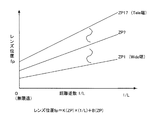
図3は光学系の距離の逆数とピントの合うレンズ位置との関係を示すグラフである。
本実施の形態では、広角Wide端ZP1〜望遠Tele端Zp17の17ポイントでズームを行うものとする。
また、一般に幾何光学的にピント合わせのレンズ位置駆動量は、距離の逆数に対して比例に近い関係にある。そこで本実施の形態では、レンズ位置駆動量と、距離の逆数とは比例関係にあるとみなし、直線に近似することで、距離Lにおけるレンズ位置fpは任意のズーム位置ZP(ただし、ZPはZP1〜ZP17)に対して下記式1で表される。
Next, a method for focusing will be described.
FIG. 3 is a graph showing the relationship between the reciprocal of the distance of the optical system and the focused lens position.
In the present embodiment, it is assumed that zooming is performed at 17 points from the wide-angle Wide end ZP1 to the telephoto telephoto end Zp17.
In general, the lens position driving amount that is geometrically focused is in a proportional relationship with the reciprocal of the distance. Therefore, in the present embodiment, the lens position driving amount and the reciprocal of the distance are considered to be in a proportional relationship and approximate to a straight line so that the lens position fp at the distance L is an arbitrary zoom position ZP (where ZP is ZP1). To ZP17) is represented by the following
fp=K(ZP)×(1/L)+B(ZP) ・・・(式1) fp = K (ZP) × (1 / L) + B (ZP) (Formula 1)
本発明に係る撮像装置内には、各ズーム位置ZPに対する無限遠におけるレンズ位置fpを意味するB(ZP)、および各ズーム位置ZPに対する距離逆数1/Lとレンズ位置fpとの比例定数である傾きK(ZP)が記憶されている。
In the imaging apparatus according to the present invention, B (ZP), which means the lens position fp at infinity with respect to each zoom position ZP, and a proportionality constant between the
ここで、焦点固定モードにおいても、1/Lを特定しておけば、各ZPにおけるK(ZP)及びB(ZP)からレンズ位置fpを上記式1で演算することができるが、ズーム(ZP)を変更した場合にピンぼけが発生することがある。
Here, even in the fixed focus mode, if 1 / L is specified, the lens position fp can be calculated from K (ZP) and B (ZP) in each ZP by the
具体的には、図4に示すようにZP1で、L0に位置する被写体で焦点固定用距離を決めたとする。
ZP1でL0にコントラスト方式のAFした場合に、レンズ位置は、メカニカルなレンズの停止分解能と、Wide端における被写界深度の広さとによりfp3aになる。(fp3aで示される横の破線はレンズが停止できる位置である)
fp3aはL1〜L2までの被写界深度±Aの範囲があるので、距離の代表点はL3となる。(コントラスト情報では被写界深度±A内の距離を正確に検出できない)
従って、Zp1よりも焦点距離が4倍あるTele端(望遠側)ZP17にズームを変更した場合では、レンズの絞り口径が変わらないとした場合に、被写界深度は1/L軸上で約1/4の±Bの範囲になるので、L3とZP17のK(ZP17)及びB(ZP17)で求めたfp3b±Bの被写界深度内に被写体が位置するL0が入らずピンぼけになる。
Specifically, as shown in FIG. 4, it is assumed that the focus fixing distance is determined by the subject located at L0 in ZP1.
When contrast AF is applied to L0 with ZP1, the lens position is fp3a depending on the stop resolution of the mechanical lens and the depth of field at the Wide end. (The horizontal broken line indicated by fp3a is a position where the lens can be stopped)
Since fp3a has a range of depth of field ± A from L1 to L2, the representative point of the distance is L3. (Contrast information cannot accurately detect distances within the depth of field ± A)
Therefore, when the zoom is changed to the telephoto end (telephoto side) ZP17 having a focal length four times that of Zp1, the depth of field is about 1 / L on the 1 / L axis when the aperture diameter of the lens is not changed. Since it is in the range of ± B of ¼, L0 where the subject is located does not enter within the depth of field of fp3b ± B obtained by K (ZP17) and B (ZP17) of L3 and ZP17, and is out of focus.
そこで、本発明に係る撮像装置では、上記ピンぼけの不具合を解消するために、以下で説明するフローに従いピント合わせを行う。
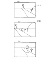
図5は本発明に係る撮像装置の第1の実施の形態におけるLCDモニタのスルー表示である。
図5(a)において、撮影したい距離Aを特定した後に、図5(b)のように画角を変えて距離Cの位置でAF範囲を合わせて、焦点固定記憶スイッチ(SW)をオンする。
焦点固定記憶スイッチは、焦点固定モードで記憶したい距離を決定・記憶(設定)するためのものである。
Therefore, in the imaging apparatus according to the present invention, in order to eliminate the above-described problem of defocusing, focusing is performed according to the flow described below.
FIG. 5 is a through display of the LCD monitor in the first embodiment of the imaging apparatus according to the present invention.
5A, after specifying the distance A to be photographed, the angle of view is changed as shown in FIG. 5B, the AF range is adjusted at the position of the distance C, and the focus fixed storage switch (SW) is turned on. .
The fixed focus storage switch is for determining and storing (setting) a distance to be stored in the fixed focus mode.
(合焦工程)
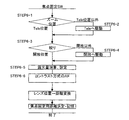
図6は、焦点固定モードにおける焦点固定用距離決定・記憶までのフローを示すブロック図である。
図2で示す撮像フローに先立ち、焦点固定記憶スイッチ(SW)がオンになると、ズーム位置がTele位置でない場合は、Tele位置に自動ズーミングし、被写界深度が狭くなるようにする。(STEP6−1、6−2)
また、絞りが開放でない場合は絞りを開放にして、被写界深度が狭くなるようにする。(STEP6−3、6−4)
(Focus process)
FIG. 6 is a block diagram showing a flow up to determining and storing a focus fixing distance in the focus fixing mode.
Prior to the imaging flow shown in FIG. 2, when the fixed focus storage switch (SW) is turned on, if the zoom position is not the Tele position, automatic zooming is performed to the Tele position so that the depth of field is reduced. (STEP 6-1, 6-2)
If the aperture is not open, the aperture is opened to reduce the depth of field. (STEP 6-3, 6-4)
尚、焦点固定記憶スイッチをオンした後でズーム又は絞りを変えた場合には、撮像素子が適当な露光量になるように、回路の利得調整や撮像素子の電子シャッターで自動調節を露光量演算・設定で行う。(STEP6−5)
次いで、コントラスト方式のAF(山登りAF)を実施し、結果のレンズ位置から焦点固定用距離を求めて決定し、カメラ内に記憶する。(STEP6−6、6−7、6−8)
If the zoom or aperture is changed after turning on the fixed focus memory switch, the exposure is calculated by adjusting the gain of the circuit and the electronic shutter of the image sensor so that the image sensor has the appropriate exposure.・ Perform by setting. (STEP 6-5)
Next, contrast-type AF (mountain climbing AF) is performed, and the focus fixing distance is obtained and determined from the resulting lens position, and stored in the camera. (STEP 6-6, 6-7, 6-8)
焦点固定用距離決定後は、カメラ使用者は自由にズーム位置を変更し、図5(c)のように被写体が所望の位置にきたらレリーズSWをオンすることで、図2で示す撮像フローが行われる。 After the focus fixing distance is determined, the camera user can freely change the zoom position, and when the subject comes to a desired position as shown in FIG. 5C, the release SW is turned on, so that the imaging flow shown in FIG. Done.
図7は本発明に係る撮像装置の第1の実施の形態におけるピント合わせのフローを示すブロック図である。
図2におけるピント合わせ処理(STEP2−2)において、焦点固定モードに設定してあるか否かを判断し(STEP7−1)、焦点固定モードに設定していれば、その時点のズーム位置と上述の図6に記載のフローで記憶した焦点固定用距離からレンズ位置を演算して、コントラスト方式のAFすることなくレンズを駆動する(STEP7−2、7−3、7−4)。焦点固定モードに設定していない場合は、コントラスト方式のAFを行ってピント合わせを行う。
ここで、STEP7−3に示すとおり、レンズ位置fpは、ZP及び焦点固定用距離の関数f(ZP,焦点固定用距離)であり、下記式2で表される。
FIG. 7 is a block diagram showing a flow of focusing in the first embodiment of the imaging apparatus according to the present invention.
In the focusing process (STEP 2-2) in FIG. 2, it is determined whether or not the focus fixing mode is set (STEP 7-1). If the focus fixing mode is set, the zoom position at that time and the above-described zoom position are set. The lens position is calculated from the focus fixing distance stored in the flow shown in FIG. 6, and the lens is driven without performing contrast AF (STEP 7-2, 7-3, 7-4). If the focus fixed mode is not set, the contrast AF is performed to focus.
Here, as shown in STEP 7-3, the lens position fp is a function f (ZP, focus fixing distance) of ZP and the focus fixing distance, and is expressed by the following
fp=f(ZP,焦点固定用距離)=K(ZP)×(1/焦点固定用距離)+B(ZP) ・・・(式2) fp = f (ZP, focus fixing distance) = K (ZP) × (1 / focus fixing distance) + B (ZP) (Expression 2)
また、焦点固定モードに設定してあるか否かを判断し(STEP7−1)、焦点固定モードに設定していない場合は、コントラスト方式のAFを行い(STEP7−5)、ピント合わせを終了する。 Also, it is determined whether or not the focus fixing mode is set (STEP 7-1). If the focus fixing mode is not set, contrast AF is performed (STEP 7-5), and the focusing is finished. .
(第2の実施の形態)
本実施の形態では、焦点固定モード、ピント合わせにおけるフロー以外は第1の実施の形態と同じ構成である。
(合焦工程)
図8は本発明に係る撮像装置の第2の実施の形態における焦点固定モードのフローを示すブロック図である。
焦点固定記憶スイッチは、焦点固定モードで記憶したい距離を設定するためのものである。本実施の形態では、図2で示す撮像フローに先立ち、焦点固定記憶スイッチ(SW)がオンになると、コントラスト方式のAF(山登りAF)を実施し(STEP8−1)、結果のレンズ位置から焦点固定用距離を求めてデジタルカメラ内に記憶する(STEP8−2、8−3)。
(Second Embodiment)
In the present embodiment, the configuration is the same as that of the first embodiment except for the fixed focus mode and the flow in focusing.
(Focus process)
FIG. 8 is a block diagram showing a flow of a fixed focus mode in the second embodiment of the imaging apparatus according to the present invention.
The fixed focus storage switch is for setting a distance to be stored in the fixed focus mode. In the present embodiment, prior to the imaging flow shown in FIG. 2, when the fixed focus memory switch (SW) is turned on, contrast AF (mountain climbing AF) is performed (STEP 8-1), and the focus is determined from the resulting lens position. The fixing distance is obtained and stored in the digital camera (STEPs 8-2 and 8-3).
また、同時にこの時のズーム位置と絞り値とをデジタルカメラ内に記憶する(STEP8−4、8−5)。
尚、ズーム位置及び絞りから決まるレンズのF値と、レンズの焦点距離と、撮像素子上での許容錯乱円径σとで、距離Lにおける被写界深度±δ1/Lは、下記式3で求まる。
At the same time, the zoom position and aperture value at this time are stored in the digital camera (STEPs 8-4 and 8-5).
Note that the depth of field ± δ1 / L at the distance L is expressed by the following Equation 3 using the F value of the lens determined from the zoom position and the aperture, the focal length of the lens, and the allowable circle of confusion diameter σ on the image sensor. I want.
±δ1/L = ±{(σ×F値)/(焦点距離)2} ・・・(式3) ± δ1 / L = ± {(σ × F value) / (focal length) 2 } (Formula 3)
図9は本発明に係る撮像装置の第2の実施の形態におけるピント合わせのフローを示すブロック図である。
図2における合焦指示を受け付けて行うピント合わせ処理(STEP2−2)において、焦点固定モードに設定してあるか否かを判断し(STEP9−1)、焦点固定モードに設定していれば、現在のレンズF値とズームの焦点距離から求めた合焦指示受付時被写界深度±δ1/L1が、上記焦点固定用距離を求めた時のレンズF値とズームの焦点距離から求める焦点固定用距離決定時被写界深度±δ1/L2に比べて(STEP9−2、9−3)、広いなら(図4の例を考えるとすると、合焦指示受付時被写界深度±δ1/L1が±A、焦点固定用距離決定時被写界深度±δ1/L2が±B)、焦点固定用距離からレンズ位置fpを演算して(STEP9−4)、コントラスト方式のAFすることなくレンズを駆動する(STEP9−5)。
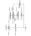
FIG. 9 is a block diagram showing a flow of focusing in the second embodiment of the imaging apparatus according to the present invention.
In the focusing process (STEP 2-2) performed by receiving the focusing instruction in FIG. 2, it is determined whether or not the focus fixing mode is set (STEP 9-1), and if the focus fixing mode is set, The depth of field ± δ1 / L 1 at the time of receiving a focusing instruction obtained from the current lens F value and the zoom focal length is the focal point obtained from the lens F value and the zoom focal length when the focus fixing distance is obtained. Compared to the depth of field ± δ1 / L 2 when fixing distance is determined (STEP 9-2, 9-3), if it is wider (considering the example of FIG. 4, the depth of field ± δ1 when receiving a focus instruction) / L 1 is ± A, the depth of field ± δ1 / L 2 is ± B when determining the focus fixing distance), the lens position fp is calculated from the focus fixing distance (STEP 9-4), and contrast type AF is performed. The lens is driven without any change (STEP 9-5).
一方、現在のレンズF値とズームの焦点距離から求めた合焦指示受付時被写界深度±δ1/L1が、上記焦点固定用距離を求めた時のレンズF値とズームの焦点距離から求める焦点固定用距離決定時被写界深度±δ1/L2に比べて狭い場合、具体的には図4の例を考えるとすると、合焦指示受付時被写界深度±δ1/L1が±B、焦点固定用距離決定時被写界深度±δ1/L2が±Aである場合、1/L3−Aの遠側距離に相当するZP17上の遠点fp3b−2と、1/L3+Aの近側距離に相当するZP17上の近点fp3b+2とを計算で求める(STEP9−6、9−7)。次いで、図4のfp範囲bに相当する誤差範囲を求め(STEP9−8)、その誤差範囲fp3b−2〜fp3b+2のコントラスト方式のAFを行うことで、好適な合焦距離を決定する(STEP9−9)。 On the other hand, the depth of field ± δ1 / L 1 at the time of receiving a focus instruction obtained from the current lens F value and the zoom focal length is obtained from the lens F value and the zoom focal length when the focus fixing distance is obtained. If it is narrower than the depth of field ± δ1 / L 2 at the time of determining the focus fixing distance, specifically, considering the example of FIG. 4, the depth of field ± δ1 / L 1 at the time of receiving the focus instruction is When the depth of field ± δ1 / L 2 at the time of determining the fixed distance for ± B and ± A is ± A, the far point fp3b-2 on ZP17 corresponding to the far side distance of 1 / L3-A and 1 / L3 + A And the near point fp3b + 2 on the ZP17 corresponding to the near side distance of is calculated (STEP 9-6, 9-7). Next, an error range corresponding to the fp range b in FIG. 4 is obtained (STEP 9-8), and a suitable focusing distance is determined by performing contrast-based AF of the error ranges fp3b-2 to fp3b + 2 (STEP 9-). 9).
また、焦点固定モードに設定してあるか否かを判断し(STEP9−1)、焦点固定モードに設定していない場合は、コントラスト方式のAFを行い(STEP9−10)、ピント合わせを終了する。 Further, it is determined whether or not the focus fixing mode is set (STEP 9-1). If the focus fixing mode is not set, the contrast AF is performed (STEP 9-10), and the focusing is finished. .
(第3の実施の形態)
本実施の形態では、ピント合わせにおけるフロー以外は第2の実施の形態と同じ構成である。
(合焦工程)
図10は本発明に係る撮像装置の第3の実施の形態におけるピント合わせのフローを示すブロック図である。
焦点固定記憶スイッチは、焦点固定モードで記憶したい距離を設定するためのものであり、本実施の形態では、第2の実施形態における焦点固定モードのフローと同じ構成である。コントラスト方式のAFを行い、焦点固定用距離、ズーム位置、絞り値がデジタルカメラ内に記憶される。
(Third embodiment)
In the present embodiment, the configuration is the same as that of the second embodiment except for the flow in focusing.
(Focus process)
FIG. 10 is a block diagram showing a flow of focusing in the third embodiment of the imaging apparatus according to the present invention.
The fixed focus storage switch is for setting a distance to be stored in the fixed focus mode, and in this embodiment, has the same configuration as the flow of the fixed focus mode in the second embodiment. Contrast AF is performed, and the focus fixing distance, zoom position, and aperture value are stored in the digital camera.
連続撮影フラグ=0の場合、即ち連続撮影を行うフラグが成立していない場合(STEP10−1)、図2における合焦指示を受け付けて行うピント合わせ処理(STEP2−2)において、焦点固定モードに設定してあるか否かを判断し(STEP10−2)、焦点固定モードに設定していれば、図10のピント合わせ処理において、現在のレンズF値とズームの焦点距離から求めた合焦指示受付時被写界深度±δ1/L1が、上記焦点固定用距離を求めた時のレンズF値とズームの焦点距離から求める焦点固定用距離決定時被写界深度±δ1/L2に比べて(STEP10−3、10−4)、広いなら(図4の例を考えるとすると、合焦指示受付時被写界深度±δ1/L1が±A、焦点固定用距離決定時被写界深度±δ1/L2が±B)焦点固定用距離からレンズ位置fpを演算して(STEP10−5)、コントラスト方式のAFすることなくレンズを駆動する(STEP10−6)。 When the continuous shooting flag = 0, that is, when the flag for performing continuous shooting is not established (STEP 10-1), in the focusing process (STEP 2-2) performed by receiving the focusing instruction in FIG. 2, the focus fixing mode is set. It is determined whether or not the focus is set (STEP 10-2), and if the focus fixing mode is set, the focus instruction obtained from the current lens F value and the zoom focal length in the focusing process of FIG. The depth of field ± δ1 / L 1 at the time of reception is compared with the depth of field ± δ1 / L 2 at the time of determining the focus fixing distance obtained from the lens F value when the focus fixing distance is obtained and the focal length of the zoom. (STEP 10-3, 10-4), if wide (considering the example of FIG. 4, the depth of field ± δ1 / L 1 at the time of receiving the focus instruction is ± A, and the field at the time of determining the focus fixing distance Depth ± δ1 / L 2 is ± B) For fixed focus The lens position fp is calculated from the distance (STEP 10-5), and the lens is driven without performing contrast AF (STEP 10-6).
一方、現在のレンズF値とズームの焦点距離から求めた合焦指示受付時被写界深度±δ1/L1が、上記焦点固定用距離を求めた時のレンズF値とズームの焦点距離から求める焦点固定用距離決定時被写界深度±δ1/L2に比べて狭い場合、具体的には図4の例を考えるとすると、合焦指示受付時被写界深度±δ1/L1が±B、焦点固定用距離決定時被写界深度±δ1/L2が±Aである場合、1/L3−Aの遠側距離に相当するZP17上の遠点fp3b−2と、1/L3+Aの近側距離に相当するZP17上の近点fp3b+2とを計算で求める(STEP10−7)。次いで、図4のfp範囲bに相当する誤差範囲(撮影レンズ範囲fp3b−2〜fp3b+2)を求め(STEP10−8)、その誤差範囲fp3b−2〜fp3b+2を記憶し、レンズ位置を上記誤差範囲開始位置fp3b−2に駆動しておく。 On the other hand, the depth of field ± δ1 / L 1 at the time of receiving a focus instruction obtained from the current lens F value and the zoom focal length is obtained from the lens F value and the zoom focal length when the focus fixing distance is obtained. If it is narrower than the depth of field ± δ1 / L 2 at the time of determining the focus fixing distance, specifically, considering the example of FIG. 4, the depth of field ± δ1 / L 1 at the time of receiving the focus instruction is When the depth of field ± δ1 / L 2 at the time of determining the fixed distance for ± B and ± A is ± A, the far point fp3b-2 on ZP17 corresponding to the far side distance of 1 / L3-A and 1 / L3 + A The near point fp3b + 2 on the ZP17 corresponding to the near side distance is calculated (STEP 10-7). Next, an error range (photographing lens range fp3b-2 to fp3b + 2) corresponding to the fp range b in FIG. Drive to position fp3b-2.
そして、誤差範囲を連続撮影する旨のフラグを立てて(STEP10−10)、誤差範囲内を連続撮影することで、複数枚の撮影画像の中から最適なピントでの撮影画像が得られる。 Then, by setting a flag indicating that the error range is continuously shot (STEP 10-10) and continuously shooting within the error range, a shot image with an optimum focus can be obtained from a plurality of shot images.
図11は本発明に係る撮像装置の第3の実施の形態における連続撮影のフローを示すブロック図である。ここで、図11は連続撮影の際の図2におけるSTEP2−6の撮影、記録保存動作を詳細に説明するブロック図である。
第二レリーズSWがオンされ実際に撮影する際に(STEP11−1)、上記誤差範囲開始位置fp3b−2から、撮像取り込み処理、画像信号処理、ファイル化処理、保存処理を行った後(STEP11−2)、撮影レンズ範囲が終了か否か(誤差範囲終了位置か否か)を判断し(STEP11−3)、終了していない場合はレンズを+1駆動し(STEP11−4)、駆動後の位置で撮影を行い、撮影レンズ範囲が終了するまで繰り返す。撮影レンズ範囲が終了したならば、連続撮影を終了する。
FIG. 11 is a block diagram showing a continuous shooting flow in the third embodiment of the imaging apparatus according to the present invention. Here, FIG. 11 is a block diagram for explaining in detail the photographing and recording storage operations of STEP 2-6 in FIG. 2 during continuous photographing.
When the second release SW is turned on and the actual shooting is performed (STEP 11-1), the image capturing process, the image signal process, the file process, and the storage process are performed from the error range start position fp3b-2 (STEP 11- 2) It is determined whether or not the photographing lens range is finished (whether or not it is the error range end position) (STEP 11-3). If not finished, the lens is driven +1 (STEP 11-4), and the position after driving Take a picture with, and repeat until the photographic lens range ends. When the photographing lens range is finished, the continuous photographing is finished.
また、焦点固定モードに設定してあるか否かを判断し(STEP10−2)、焦点固定モードに設定していない場合は、コントラスト方式のAFを行い(STEP10−11)、ピント合わせを終了する。 Further, it is determined whether or not the focus fixing mode is set (STEP 10-2). If the focus fixing mode is not set, the contrast AF is performed (STEP 10-11), and the focusing is finished. .
(第4の実施の形態)
本実施の形態では、ピント合わせにおけるフロー以外は第2の実施の形態と同じ構成である。
(Fourth embodiment)
In the present embodiment, the configuration is the same as that of the second embodiment except for the flow in focusing.
(合焦工程)
図12は本発明に係る撮像装置の第4の実施の形態におけるピント合わせのフローを示すブロック図である。
図2における合焦指示を受け付けて行うピント合わせ処理(STEP2−2)において、焦点固定モードに設定してあるか否かを判断し(STEP11−1)、焦点固定モードに設定していれば、図11のピント合わせ処理において、現在のレンズF値とズームの焦点距離から求めた合焦指示受付時被写界深度±δ1/L1が、上記焦点固定用距離を求めた時のレンズF値とズームの焦点距離から求める焦点固定用距離決定時被写界深度±δ1/L2に比べて(STEP11−2、11−3)、広いなら(図4の例を考えるとすると、合焦指示受付時被写界深度±δ1/L1が±A、焦点固定用距離決定時被写界深度±δ1/L2が±B)焦点固定用距離からレンズ位置fpを演算して(STEP11−4)、コントラスト方式のAFすることなくレンズを駆動する(STEP11−5)。
(Focus process)
FIG. 12 is a block diagram showing a flow of focusing in the fourth embodiment of the imaging apparatus according to the present invention.
In the focusing process (STEP 2-2) performed by receiving the focus instruction in FIG. 2, it is determined whether or not the focus fixing mode is set (STEP 11-1), and if the focus fixing mode is set, In the focusing process of FIG. 11, the depth of field ± δ1 / L 1 at the time of receiving the focus instruction obtained from the current lens F value and the focal length of the zoom is the lens F value when the focus fixing distance is obtained. And the depth of field ± δ1 / L 2 at the time of determining the focus fixing distance obtained from the focal length of the zoom (STEP 11-2, 11-3), if it is wider (considering the example of FIG. When receiving, the depth of field ± δ1 / L 1 is ± A, and when determining the focus fixing distance, the depth of field ± δ1 / L 2 is ± B) and calculating the lens position fp from the focus fixing distance (STEP 11-4) ) Ren without contrast AF Is driven (STEP 11-5).
一方、現在のレンズF値とズームの焦点距離から求めた合焦指示受付時被写界深度±δ1/L1が、上記焦点固定用距離を求めた時のレンズF値とズームの焦点距離から求める焦点固定用距離決定時被写界深度±δ1/L2に比べて狭い場合、具体的には図4の例を考えるとすると、合焦指示受付時被写界深度±δ1/L1が±B、焦点固定用距離決定時被写界深度±δ1/L2が±Aである場合、ピントが合わない可能性があるので、LCD表示に警告文字を表示する警告、または警告音による警告を行う(STEP11−6)。 On the other hand, the depth of field ± δ1 / L 1 at the time of receiving a focus instruction obtained from the current lens F value and the zoom focal length is obtained from the lens F value and the zoom focal length when the focus fixing distance is obtained. If it is narrower than the depth of field ± δ1 / L 2 at the time of determining the focus fixing distance, specifically, considering the example of FIG. 4, the depth of field ± δ1 / L 1 at the time of receiving the focus instruction is When the depth of field ± δ1 / L 2 is ± A when determining the focus distance for ± B, the focus may not be met, so a warning that displays a warning character on the LCD display or a warning sound (STEP 11-6).
また、焦点固定モードに設定してあるか否かを判断し(STEP11−1)、焦点固定モードに設定していない場合は、コントラスト方式のAFを行い(STEP11−7)、ピント合わせを終了する。 Further, it is determined whether or not the focus fixing mode is set (STEP 11-1). If the focus fixing mode is not set, the contrast AF is performed (STEP 11-7), and the focusing is finished. .
上記第1〜4の実施の形態のデジタルカメラによれば、画角を変化させても、同一の焦点固定距離にピントを正確に素早く合わせることが可能である。 According to the digital cameras of the first to fourth embodiments, it is possible to focus quickly and accurately on the same fixed focal length even if the angle of view is changed.
1 ストロボ発光部
4 鏡胴ユニット
5 LCDモニタ
101 CCD
102 F/E−IC
103 SDRAM
104 ディジタルスチルカメラプロセッサ
105 SUB CPU
106 ストロボ回路
107 内蔵メモリ
108 LCDドライバ
109 ビデオAMP
110 ビデオジャック
112 音声CODEC
113 スピーカー
DESCRIPTION OF
102 F / E-IC
103 SDRAM
104 Digital
106
110
113 Speaker
Claims (10)
前記撮像光学系により結像された被写体像を電気信号に変換して出力する撮像手段と、
前記撮像手段からの電気信号に基づいて合焦度合いを判断する合焦手段と、
合焦指示を受け付ける合焦指示受付手段と、を備え、
前記合焦手段は、前記撮像手段からの電気信号に基づいて焦点固定用距離を決定し、
前記合焦指示受付手段が合焦指示を受け付けた際の合焦指示受付時被写界深度が、前記焦点固定用距離を決定する際の焦点固定用距離決定時被写界深度よりも広いときは、前記撮像光学系の合焦距離を、前記焦点固定用距離とし、
前記合焦指示受付時被写界深度が、前記焦点固定用距離決定時被写界深度よりも狭いときは、前記焦点固定用距離決定時被写界深度に相当する範囲において前記撮像手段からの電気信号に基づいて合焦度合いを判断し、前記撮像光学系の合焦距離を決定することを特徴とする合焦装置。 An imaging optical system;
Imaging means for converting a subject image formed by the imaging optical system into an electrical signal and outputting the electrical signal;
Focusing means for determining the degree of focusing based on an electrical signal from the imaging means;
Focusing instruction receiving means for receiving a focusing instruction,
The focusing means determines a focus fixing distance based on an electrical signal from the imaging means,
When the depth of field at the time of focus instruction reception when the focus instruction reception unit receives the focus instruction is wider than the depth of field at the time of determining the focus fixing distance when determining the focus fixing distance Is the in-focus distance of the imaging optical system as the focus fixing distance,
When the depth of field at the time of receiving the focus instruction is narrower than the depth of field at the time of determining the focus fixing distance, the imaging means from the imaging unit within a range corresponding to the depth of field at the time of determining the focus fixing distance. A focusing device that determines a focusing distance of the imaging optical system by determining a degree of focusing based on an electrical signal.
前記撮像光学系により結像された被写体像を電気信号に変換して出力する撮像手段と、
前記撮像手段からの電気信号に基づいて合焦度合いを判断する合焦手段と、
合焦指示を受け付ける合焦指示受付手段と、を備え、
前記合焦手段は、前記撮像手段からの電気信号に基づいて焦点固定用距離を決定し、
前記合焦指示受付手段が合焦指示を受け付けた際の合焦指示受付時被写界深度が、前記焦点固定用距離を決定する際の焦点固定用距離決定時被写界深度よりも広いときは、前記撮像光学系の合焦距離を、前記焦点固定用距離とし、
前記合焦指示受付時被写界深度が、前記焦点固定用距離決定時被写界深度よりも狭いときは、前記焦点固定用距離決定時被写界深度に相当する範囲における複数個所で合焦動作を行うことを特徴とする合焦装置。 An imaging optical system;
Imaging means for converting a subject image formed by the imaging optical system into an electrical signal and outputting the electrical signal;
Focusing means for determining the degree of focusing based on an electrical signal from the imaging means;
Focusing instruction receiving means for receiving a focusing instruction,
The focusing means determines a focus fixing distance based on an electrical signal from the imaging means,
When the depth of field at the time of focus instruction reception when the focus instruction reception unit receives the focus instruction is wider than the depth of field at the time of determining the focus fixing distance when determining the focus fixing distance Is the in-focus distance of the imaging optical system as the focus fixing distance,
When the depth of field at the time of receiving the focus instruction is narrower than the depth of field at the time of determining the focus fixing distance, focusing is performed at a plurality of positions in a range corresponding to the depth of field at the time of determining the focus fixing distance. A focusing apparatus characterized by performing an operation.
前記撮像光学系により結像された被写体像を電気信号に変換して出力する撮像手段と、
前記撮像手段からの電気信号に基づいて合焦度合いを判断する合焦手段と、
合焦指示を受け付ける合焦指示受付手段と、
警告手段と、を備え、
前記合焦手段は、前記撮像手段からの電気信号に基づいて焦点固定用距離を決定し、
前記合焦指示受付手段が合焦指示を受け付けた際の合焦指示受付時被写界深度が、前記焦点固定用距離を決定する際の焦点固定用距離決定時被写界深度よりも広いときは、前記撮像光学系の合焦距離を、前記焦点固定用距離とし、
前記警告手段は、前記合焦指示受付時被写界深度が、前記焦点固定用距離決定時被写界深度よりも狭いときは、警告を行うことを特徴とする合焦装置。 An imaging optical system;
Imaging means for converting a subject image formed by the imaging optical system into an electrical signal and outputting the electrical signal;
Focusing means for determining the degree of focusing based on an electrical signal from the imaging means;
A focusing instruction receiving means for receiving a focusing instruction;
A warning means,
The focusing means determines a focus fixing distance based on an electrical signal from the imaging means,
When the depth of field at the time of focus instruction reception when the focus instruction reception unit receives the focus instruction is wider than the depth of field at the time of determining the focus fixing distance when determining the focus fixing distance Is the in-focus distance of the imaging optical system as the focus fixing distance,
The focusing device is characterized in that the warning means warns when the depth of field at the time of receiving the focus instruction is narrower than the depth of field at the time of determining the focus fixing distance.
前記撮像光学系により結像された被写体像を電気信号に変換して出力する撮像手段と、
前記撮像手段からの電気信号に基づいて合焦度合いを判断する合焦手段と、を備え、
前記撮像光学系は、ズームレンズと、フォーカスレンズと、絞りと、を有し、
前記合焦手段は、前記ズームレンズ及び前記絞りを制御して被写界深度を狭くした状態の前記撮像手段からの電気信号に基づいて焦点固定用距離を決定し、撮像光学系の合焦距離とすることを特徴とする合焦装置。 An imaging optical system;
Imaging means for converting a subject image formed by the imaging optical system into an electrical signal and outputting the electrical signal;
Focusing means for determining the degree of focusing based on an electrical signal from the imaging means,
The imaging optical system has a zoom lens, a focus lens, and a diaphragm,
The focusing unit determines a focus fixing distance based on an electrical signal from the imaging unit in a state where the depth of field is narrowed by controlling the zoom lens and the diaphragm, and a focusing distance of the imaging optical system A focusing device characterized by that.
合焦指示を受け付ける合焦指示受付工程と、を備え、
前記合焦工程は、前記電気信号に基づいて焦点固定用距離を決定した後、
前記合焦指示受付工程が合焦指示を受け付けた際の合焦指示受付時被写界深度が、前記焦点固定用距離を決定する際の焦点固定用距離決定時被写界深度よりも広いときは、前記撮像光学系の合焦距離を、前記焦点固定用距離とし、
前記合焦指示受付時被写界深度が、前記焦点固定用距離決定時被写界深度よりも狭いときは、さらに前記焦点固定用距離決定時被写界深度に相当する範囲において前記電気信号に基づいて合焦度合いを判断し、前記撮像光学系の合焦距離を決定することを特徴とする合焦方法。 A focusing step for determining a degree of focusing based on an electrical signal obtained by converting a subject image formed by the imaging optical system;
A focusing instruction receiving step for receiving a focusing instruction,
In the focusing step, after determining the focus fixing distance based on the electrical signal,
When the depth of field at the time of focus instruction reception when the focus instruction reception step receives the focus instruction is wider than the depth of field at the time of determining the focus fixing distance when determining the focus fixing distance Is the in-focus distance of the imaging optical system as the focus fixing distance,
When the depth of field at the time of receiving the focus instruction is narrower than the depth of field at the time of determining the focus fixing distance, the electric signal is further converted into the electric signal in a range corresponding to the depth of field at the time of determining the focus fixing distance. An in-focus method, wherein the in-focus degree is determined based on the in-focus distance of the imaging optical system.
合焦指示を受け付ける合焦指示受付工程と、を備え、
前記合焦工程は、前記電気信号に基づいて焦点固定用距離を決定した後、
前記合焦指示受付工程が合焦指示を受け付けた際の合焦指示受付時被写界深度が、前記焦点固定用距離を決定する際の焦点固定用距離決定時被写界深度よりも広いときは、前記撮像光学系の合焦距離を、前記焦点固定用距離とし、
前記合焦指示受付時被写界深度が、前記焦点固定用距離決定時被写界深度よりも狭いときは、前記焦点固定用距離決定時被写界深度に相当する範囲における複数個所で合焦動作を行うことを特徴とする合焦方法。 A focusing step for determining a degree of focusing based on an electrical signal obtained by converting a subject image formed by the imaging optical system;
A focusing instruction receiving step for receiving a focusing instruction,
In the focusing step, after determining the focus fixing distance based on the electrical signal,
When the depth of field at the time of focus instruction reception when the focus instruction reception step receives the focus instruction is wider than the depth of field at the time of determining the focus fixing distance when determining the focus fixing distance Is the in-focus distance of the imaging optical system as the focus fixing distance,
When the depth of field at the time of receiving the focus instruction is narrower than the depth of field at the time of determining the focus fixing distance, focusing is performed at a plurality of positions in a range corresponding to the depth of field at the time of determining the focus fixing distance. A focusing method characterized by performing an action.
合焦指示を受け付ける合焦指示受付工程と、を備え、
前記合焦工程は、前記電気信号に基づいて焦点固定用距離を決定した後、
前記合焦指示受付工程が合焦指示を受け付けた際の合焦指示受付時被写界深度が、前記焦点固定用距離を決定する際の焦点固定用距離決定時被写界深度よりも広いときは、前記撮像光学系の合焦距離を、前記焦点固定用距離とし、
前記合焦指示受付時被写界深度が、前記焦点固定用距離決定時被写界深度よりも狭いときは、警告を行うことを特徴とする合焦方法。 A focusing step for determining a degree of focusing based on an electrical signal obtained by converting a subject image formed by the imaging optical system;
A focusing instruction receiving step for receiving a focusing instruction,
In the focusing step, after determining the focus fixing distance based on the electrical signal,
When the depth of field at the time of focus instruction reception when the focus instruction reception step receives the focus instruction is wider than the depth of field at the time of determining the focus fixing distance when determining the focus fixing distance Is the in-focus distance of the imaging optical system as the focus fixing distance,
An in-focus method characterized in that a warning is given when the depth of field at the time of receiving the in-focus instruction is narrower than the depth of field at the time of determining the focus fixing distance.
前記撮像光学系は、ズームレンズと、フォーカスレンズと、絞りと、を有し、
前記ズームレンズ及び前記絞りを制御して被写界深度を狭くした状態の電気信号に基づいて焦点固定用距離を決定し、撮像光学系の合焦距離とすることを特徴とする合焦方法。 In a focusing method for determining a focusing degree based on an electrical signal obtained by converting a subject image formed by an imaging optical system,
The imaging optical system has a zoom lens, a focus lens, and a diaphragm,
A focusing method characterized by determining a focus fixing distance based on an electrical signal in a state in which the zoom lens and the diaphragm are controlled to reduce the depth of field, and set it as a focusing distance of the imaging optical system.
Priority Applications (1)
| Application Number | Priority Date | Filing Date | Title |
|---|---|---|---|
| JP2007323398A JP2009145670A (en) | 2007-12-14 | 2007-12-14 | Focusing device and focusing method |
Applications Claiming Priority (1)
| Application Number | Priority Date | Filing Date | Title |
|---|---|---|---|
| JP2007323398A JP2009145670A (en) | 2007-12-14 | 2007-12-14 | Focusing device and focusing method |
Publications (1)
| Publication Number | Publication Date |
|---|---|
| JP2009145670A true JP2009145670A (en) | 2009-07-02 |
Family
ID=40916316
Family Applications (1)
| Application Number | Title | Priority Date | Filing Date |
|---|---|---|---|
| JP2007323398A Pending JP2009145670A (en) | 2007-12-14 | 2007-12-14 | Focusing device and focusing method |
Country Status (1)
| Country | Link |
|---|---|
| JP (1) | JP2009145670A (en) |
Cited By (1)
| Publication number | Priority date | Publication date | Assignee | Title |
|---|---|---|---|---|
| US9001258B2 (en) | 2011-12-07 | 2015-04-07 | Seiko Epson Corporation | Image capturing device and image capturing method |
Citations (2)
| Publication number | Priority date | Publication date | Assignee | Title |
|---|---|---|---|---|
| JP2006018246A (en) * | 2004-06-03 | 2006-01-19 | Canon Inc | Imaging apparatus and imaging method |
| JP2007174521A (en) * | 2005-12-26 | 2007-07-05 | Nikon Corp | Movie shooting device |
-
2007
- 2007-12-14 JP JP2007323398A patent/JP2009145670A/en active Pending
Patent Citations (2)
| Publication number | Priority date | Publication date | Assignee | Title |
|---|---|---|---|---|
| JP2006018246A (en) * | 2004-06-03 | 2006-01-19 | Canon Inc | Imaging apparatus and imaging method |
| JP2007174521A (en) * | 2005-12-26 | 2007-07-05 | Nikon Corp | Movie shooting device |
Cited By (1)
| Publication number | Priority date | Publication date | Assignee | Title |
|---|---|---|---|---|
| US9001258B2 (en) | 2011-12-07 | 2015-04-07 | Seiko Epson Corporation | Image capturing device and image capturing method |
Similar Documents
| Publication | Publication Date | Title |
|---|---|---|
| JP5005570B2 (en) | Image processing apparatus and program | |
| JP4127491B2 (en) | Camera with auto focus function | |
| JP2005241805A (en) | Autofocus device and program thereof | |
| JP2009251557A (en) | Imaging apparatus | |
| JP2010187225A (en) | Imaging apparatus and imaging method | |
| JP2010045625A (en) | Imaging apparatus | |
| JP2009031702A (en) | Imaging apparatus and imaging method | |
| JP5432664B2 (en) | Imaging device | |
| CN107255900B (en) | Control method of photographing device | |
| JP2010068134A (en) | Image pickup apparatus and image pickup control method | |
| KR101462323B1 (en) | Imaging device and imaging method | |
| JP5100410B2 (en) | Imaging apparatus and control method thereof | |
| JP2016142924A (en) | Imaging apparatus, control method therefor, program, and storage medium | |
| JP2012093409A (en) | Image-pickup device and image-pickup method | |
| JP2011217334A (en) | Imaging apparatus and method of controlling the same | |
| JP5486662B2 (en) | Imaging device and camera body | |
| WO2010131727A1 (en) | Digital camera | |
| JP4855155B2 (en) | Imaging apparatus and imaging method using the same | |
| JP2003232986A (en) | Camera | |
| JP2003241066A (en) | Camera | |
| JP2009145670A (en) | Focusing device and focusing method | |
| JP5418553B2 (en) | Imaging apparatus and imaging method using the same | |
| JP2005017673A (en) | Method for searching for focusing position of focus lens, and imaging apparatus | |
| JP4496051B2 (en) | Imaging device | |
| JP2003222787A (en) | Digital camera |
Legal Events
| Date | Code | Title | Description |
|---|---|---|---|
| A621 | Written request for application examination |
Free format text: JAPANESE INTERMEDIATE CODE: A621 Effective date: 20100804 |
|
| A977 | Report on retrieval |
Free format text: JAPANESE INTERMEDIATE CODE: A971007 Effective date: 20110912 |
|
| A131 | Notification of reasons for refusal |
Free format text: JAPANESE INTERMEDIATE CODE: A131 Effective date: 20110927 |
|
| A02 | Decision of refusal |
Free format text: JAPANESE INTERMEDIATE CODE: A02 Effective date: 20120403 |