EP3796792B1 - Générateur de chaleur pour des pipes à eau - Google Patents
Générateur de chaleur pour des pipes à eau Download PDFInfo
- Publication number
- EP3796792B1 EP3796792B1 EP19726930.1A EP19726930A EP3796792B1 EP 3796792 B1 EP3796792 B1 EP 3796792B1 EP 19726930 A EP19726930 A EP 19726930A EP 3796792 B1 EP3796792 B1 EP 3796792B1
- Authority
- EP
- European Patent Office
- Prior art keywords
- heat generator
- slot
- plate
- heat
- tobacco
- Prior art date
- Legal status (The legal status is an assumption and is not a legal conclusion. Google has not performed a legal analysis and makes no representation as to the accuracy of the status listed.)
- Active
Links
Images


Classifications
-
- A—HUMAN NECESSITIES
- A24—TOBACCO; CIGARS; CIGARETTES; SIMULATED SMOKING DEVICES; SMOKERS' REQUISITES
- A24F—SMOKERS' REQUISITES; MATCH BOXES; SIMULATED SMOKING DEVICES
- A24F1/00—Tobacco pipes
- A24F1/30—Hookahs
Definitions
- the present invention relates to a water pipe heater.
- heat generators are mainly used in smoking devices such as shishas.
- the heat generator is filled with a heat source, for example glowing lumps of coal.
- a tobacco or tobacco substitute arranged below the heat generator is heated by the heat emitted by the heat generator and in the process releases its flavoring ingredients. These are then consumed by the smoker, but first pulled through a container filled with water.
- US2017/0265520 discloses a known water pipe heater.
- the heat supply can only be regulated satisfactorily by removing or adding additional heating material.
- the smokers may wish to develop a lot of heat, which is achieved by bringing the heat source very close to the tobacco material.
- the regulation of the temperature requires direct intervention by the user on the heat source.
- the object is achieved by a heat generator according to claim 1.
- the heat generator for hookahs is designed as a vessel that includes a peripheral wall, a bottom, a cover part, and a plate arranged movably inside the heat generator for receiving glowing coals or coal substitutes.
- the object according to the invention is achieved in that at least one guide slot is arranged in the peripheral wall of the heat generator and extends helically between the base and the cover part.
- the plate has at least one handle part that projects through the slot and is guided in the slot, and its position can be continuously adjusted relative to the base of the heat generator. This configuration allows the distance between the charcoal and the bottom of the heat generator to be regulated individually from the outside after the heat generator has been filled once with charcoal, and no direct intervention in the charcoal is necessary after filling. This avoids unnecessary opening of the heat generator and also prevents burn injuries.
- the slot has latching positions for the handle part and the handle part is supported on the peripheral wall inside the slot. This makes it possible to set a preferred distance between coal and ground.
- the bottom has a guide for the plate that extends in the axial direction of the heat generator, so that the plate can always be moved evenly and safely and that it can be mounted horizontally.
- two opposing, symmetrically designed slots are provided in the peripheral wall and the plate has two handle parts, of which at least one protrudes through the slot and a second protrudes into the slot. This further improves the guidance of the plate when it is moved in the heat generator. In this embodiment, too, it is considered favorable if the slots have latching positions for the handle parts.
- the plate has holes in a preferred embodiment.
- the plate has a peripheral edge which rests, in particular in a sealing manner, on the peripheral wall.
- the insertion of the coals is significantly simplified if the plate has a bulge aligned towards the bottom.
- the heat generator preferably has a dome, cone, truncated cone, pyramid or hemispherical shape.
- the geometric shape which is not limited to the above, ensures optimal heat circulation inside the generator.
- a variation of the shape also proves to be particularly favorable from an optical point of view.
- the heat generator has an access or filling opening through which fuel can be introduced into the heat generator.
- the heat generator is characterized in that the cover part is designed to be removable.
- the cover part has at least one ventilation opening, in particular a round or slot-shaped or oblong-shaped ventilation opening.
- provision can also be made for the cover part to be pivoted relative to the body of the heat generator. The pivoting can take place in one plane or out of the plane.
- a slide for opening and closing the at least one ventilation opening is provided in the cover part.
- the burning process is further influenced by the opening or closing of the ventilation openings and the development of heat is thus promoted or reduced.
- the cover part and slide are arranged such that they can be displaced relative to one another and/or in opposite directions to one another.
- At least one ventilation opening in particular round or slot-shaped or slot-shaped, is also provided in the peripheral wall. This is used for ventilation and thus for more even combustion of the material.
- the heat generator has a grip tab that allows the heat generator to be gripped easily and, above all, without burning it, even if it is already filled with glowing coal.
- the heat generator is advantageously made of aluminum, stainless steel or a heat-resistant plastic and is preferably produced in a casting, die-casting, deep-drawing, forging process or in a machining process.
- the hookah tobacco bowl has at least one hookah tobacco bowl body and a tobacco support part and is characterized in that the hookah tobacco bowl body is essentially hollow.
- This hollow configuration allows it to be filled with a liquid, for example water or a cooling liquid.
- a liquid for example water or a cooling liquid.
- the cooled water pipe tobacco head prevents the tobacco material from burning up too quickly when the heat source is attached. This achieves an even aroma development and thus an advantageous smoking result.
- this preferably has a filling opening.
- the water pipe tobacco head is subjected to high heat, it is considered favorable if the entire water pipe tobacco head or only the water pipe tobacco head body and/or the tobacco support part is/are made entirely or partially of a heat-resistant material, in particular silicone.
- a heat-resistant material in particular silicone.
- conventional materials such as stone, ceramics, clay, glass, metal or porcelain are completely or partially replaced and the manufacture of the tobacco bowl is significantly simplified and reduced in price.
- Water pipe tobacco head body and/or the tobacco support part are regarded as favorable materials for the production of the parts of the water pipe tobacco head, tobacco head body and/or tobacco support part that are not made of silicone.
- Water pipe tobacco head body and/or the tobacco support part are preferably produced in a casting, die-casting, deep-drawing, blow molding or forging process or in a machining process, with the process used depending on the material, the material properties and the workability.
- the water pipe tobacco head body and/or the tobacco support part can be made of different materials are formed and a detachable or fixed connection of water pipe tobacco head body and tobacco support part is provided.
- the detachable connection can be designed, for example, as a screw or plug connection.
- a non-detachable connection is created by fusing or gluing the two parts together.
- the tobacco support part is designed in the form of a trough or bowl and is sunk into a cavity in the water pipe tobacco bowl body. This achieves a further improvement in the cooling properties and performance.
- the water pipe tobacco bowl body can be filled completely or partially with liquid, in particular a cooling liquid.
- liquid in particular a cooling liquid.
- the filling opening is designed to be resealable. This means that the coolant can be refilled or replaced after use.
- the cooling of the tobacco is further enhanced when the surface of the tobacco support part facing the cavity contacts the liquid.
- the water pipe tobacco bowl is intended for a heat generator to be placed on it, for example as described above.
- the latter preferably has a receptacle, in particular an insert groove or depression for the low-play connection to the heat generator.
- means for forming a detachable connection between the heat generator and/or the water pipe tobacco bowl can be provided as an alternative or in addition. In this context, it is considered favorable if these means are designed as snap-in receptacles, screw connectors, plug connectors or magnetic connectors that can be brought into engagement with one another.
- FIG. 1 shows a conventional water pipe 1, which is also known under the term shisha. This has several parts in the embodiment.
- the water pipe 1 shown here has a vessel 60 filled with water, which forms the lower part 40 of the water pipe 1 .
- the connection opening 50 for the in figure 1 not shown smoke hose provided.
- Corresponding tubes for the smoke line are provided inside the vessel 60 .
- the upper part 70 of the water pipe 1 is formed by an ash plate 71 to which the water pipe tobacco bowl 30 is connected.
- the water pipe tobacco head 30 also has a tobacco receiving tray 20 on which tobacco can be placed.
- the system is completed by a heat generator 10 that can be placed on the water pipe tobacco bowl 30. The two latter elements are described in detail in the following drawings.
- FIG. 2a shows a heat generator 10 in a perspective view.
- This has a hemispherical cover 11 which is provided with ventilation openings 110 .
- a gripping projection 121 which is used for pivoting the cover 11 and opening the heat generator 10 is formed on the cover 11 .
- the heat generator 10 also has a peripheral wall 13 which, in the exemplary embodiment, is provided with a helically circumferential slot 14 made in the peripheral wall 13 .
- the slot 14 serves as a guide for the handle part 16 which is attached to the plate 120 arranged inside the heat generator 10 .
- the slot 14 has latching positions 17 into which the handle part 16 can be lowered. It is thus possible to adjust the plate 120 inside the heat generator 10 almost steplessly.
- the peripheral wall 13 has ventilation holes 19 in the exemplary embodiment shown here.
- a grip tab 15 is also provided between the base 18 and the cover 11 approximately centrally in the peripheral wall 13 .
- the heat generator 10 can be raised via this and placed, for example, on a hookah tobacco bowl 30 .
- FIG. 2b shows the connection with Figure 2a described heat generator 10 in a sectional view.
- the plate 120 which is arranged inside the heat generator 10 and which serves as a support for coals when the water pipe 1 is in operation can be clearly seen here.
- the handle part 16 is arranged on the plate 120 and extends outwards through the peripheral wall 13 and the slot 14 arranged therein.
- the position of the plate 120 inside the heat generator 10 can be changed via the handle part 16 by the handle part 16 being displaced along the slot 14 provided in the peripheral wall 13 .
- the distance between the plate 120 and the glowing charcoal placed on it (not shown) and the bottom 18 of the heat generator 10 then changes 18 and the cover 11 extending guide rod 122 is provided, along which the plate 120 can be displaced axially.
- the cover 11 has a slide 113 which can be displaced relative to the cover 11 and closes or opens the ventilation openings 110 in the cover 11 .
- the ventilation holes 19 in the peripheral wall 13 are always open and allow air to enter, which has a positive effect on the annealing process.
- figure 3 shows a further embodiment of the heat generator 10. This also has a slot 14 in the peripheral wall 13 , in which a handle part 16 of the plate 120 arranged in the interior can be displaced. In this exemplary embodiment, the locking positions 17 into which the handle part 16 can be inserted are clearly visible.
- the heat generator 10 of figure 3 also has a cover 11 in which ventilation openings 110 are provided. These are slot-shaped. One Regulation of the opening width is not provided here, which is why no slider is installed.
- the cover 11 shown here is not pivotable but is opened.
- the grip projection 121 which coincides with the grip tab 15 on the circumference 13 , is used for this purpose.
- any other configuration of the cover 11 that appears favorable and is desired from an optical point of view can, of course, be selected.
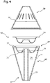
- FIG 4 a hookah tobacco bowl 30 is shown.
- this is designed as a hollow structure and has an outer wall 31 which delimits a receiving space 36 for a liquid, for example coolant.
- the receiving space 36 has a shell receptacle 34 into which a tobacco receiving shell 20 can be inserted.
- the tobacco receiving shell 20 is made of metal, for example, and can be removed and cleaned after the end of the smoking process.
- the shell receptacle 34 or its shell bottom 33 curves in the direction of the receiving space 36 inside the hookah tobacco bowl 30 and makes contact with the cooling liquid provided there.
- the use of the cooling liquid has the advantage that the tobacco remains cooled and does not burn until the coal inserted in the heat generator 10 has reached its operating temperature.
- the heat generator 10 is placed on the water pipe tobacco bowl 30 .
- the exemplary embodiment figure 4 embedded in the upper circumferential edge 38 of the hookah tobacco head 30 magnets 35 , preferably pressed, which hold the heat generator 10 made of metal on the hookah tobacco head 30 .
- Alternative embodiments not shown here provide a receiving groove or depression into which the heat generator or its lower edge can be inserted.
- the elements of the heat generator 10 have already been described above, so these elements will not be described again.
- At the lower end 37 of the water pipe tobacco head 30 tapers and can be used with this lower end 37 in a bottle and close it like a stopper.
- the hookah tobacco head 30 is shown in the embodiment as a one-piece element and consists of a silicone material. Of course, there is also the possibility that different materials are combined here, for example in a corresponding injection molding process.
- the water pipe tobacco head body 80 is hollow and, in the exemplary embodiment, carries the tobacco support part 90, which is additionally occupied here with a tobacco receiving shell 20 to be inserted into the shell receptacle 34.
Landscapes
- Thermotherapy And Cooling Therapy Devices (AREA)
- Manufacture Of Tobacco Products (AREA)
Claims (15)
- Générateur de chaleur (10) pour des pipes à eau (1) comprenant:- une paroi circonférentielle (13),- un fond (18),- une partie couvercle (11), et- une plaque (120) disposée de manière mobile à l'intérieur du générateur de chaleur (10) pour recevoir des charbons incandescents ou des substituts de charbon,caractérisé en ce qu'au moins une fente (14) est disposée dans la paroi périphérique (13) du générateur de chaleur (10), laquelle s'étend en forme de spirale entre le fond (18) et la partie de couvercle (11), et la plaque (120) présente au moins une partie de poignée (16) faisant saillie à travers la fente (14) et guidée dans la fente (14), et une possibilité de réglage en continu de la plaque (120) par rapport au fond (18) est prévue.
- Générateur de chaleur (10) selon la revendication 1, caractérisé en ce que la fente (14) présente des positions d'encliquetage pour la partie de poignée (16) et la partie de poignée (16) est supportée sur la paroi circonférentielle à l'intérieur de la fente (14).
- Générateur de chaleur (10) selon la revendication 1 ou 2, caractérisé en ce que la base (18) présente un guide pour la plaque (120) s'étendant dans la direction axiale du générateur de chaleur (10).
- Générateur de chaleur (10) selon l'une des revendications précédentes, caractérisé en ce que deux fentes (14) opposées, formées symétriquement, sont prévues dans la paroi périphérique (13) et la plaque (120) présente deux parties de préhension, dont au moins une fait saillie à travers la fente (14) et une deuxième fait saillie dans la fente (14), les fentes (14) présentant notamment des positions d'encliquetage (17) pour les parties de préhension (16).
- Générateur de chaleur (10) selon l'une des revendications précédentes, caractérisé en ce que la plaque (120) présente des trous et/ou la plaque (120) présente un bord périphérique qui s'appuie sur la paroi périphérique (13), en particulier de manière étanche.
- Générateur de chaleur (10) selon l'une quelconque des revendications précédentes, caractérisé en ce que la plaque (120) présente une courbure orientée vers le fond (18).
- Générateur de chaleur (10) selon l'une quelconque des revendications précédentes, caractérisé en ce qu'il présente une forme de dôme, de cône, de cône tronqué, de pyramide ou d'hémisphère.
- Générateur de chaleur (10) selon l'une quelconque des revendications précédentes, caractérisé en ce que le générateur de chaleur (10) comprend une ouverture d'accès ou de remplissage.
- Générateur de chaleur (10) selon l'une des revendications précédentes, caractérisé en ce que la partie couvercle (11) est conçue pour être amovible.
- Générateur de chaleur (10) selon l'une des revendications précédentes, caractérisé en ce que la partie de couvercle (11) présente au moins une ouverture de ventilation (110), notamment ronde ou en forme de fente ou de trou allongé.
- Générateur de chaleur (10) selon la revendication 10, caractérisé en ce qu'un coulisseau (113) pour ouvrir et fermer la au moins une ouverture de ventilation (110) est prévu dans la partie de couvercle (11).
- Générateur de chaleur (10) selon la revendication 11, caractérisé en ce que la partie de couvercle (11) et le curseur (113) sont disposés de manière à pouvoir être déplacés l'un par rapport à l'autre et/ou dans des directions opposées.
- Générateur de chaleur (10) selon l'une des revendications précédentes, caractérisé en ce qu'au moins une ouverture d'aération (110), en particulier ronde ou en forme de fente ou de trou allongé, est prévue dans la paroi périphérique (13).
- Générateur de chaleur (10) selon l'une quelconque des revendications précédentes, caractérisé en ce que le générateur de chaleur (10) comprend une poignée (15) ou une patte de poignée (121).
- Générateur de chaleur (10) selon l'une des revendications précédentes, caractérisé en ce que le générateur de chaleur (10) est formé d'aluminium, d'acier inoxydable ou d'une matière plastique résistant à la chaleur et/ou le générateur de chaleur (10) est de préférence fabriqué dans un procédé de coulée, de moulage sous pression, d'emboutissage, de forgeage ou dans un procédé d'usinage.
Applications Claiming Priority (2)
| Application Number | Priority Date | Filing Date | Title |
|---|---|---|---|
| DE202018102820.0U DE202018102820U1 (de) | 2018-05-21 | 2018-05-21 | Wärmeerzeuger für Wasserpfeifen und Wasserpfeifentabakkopf |
| PCT/EP2019/062749 WO2019224112A1 (fr) | 2018-05-21 | 2019-05-16 | Générateur de chaleur pour des pipes à eau et foyer de pipe à eau |
Publications (2)
| Publication Number | Publication Date |
|---|---|
| EP3796792A1 EP3796792A1 (fr) | 2021-03-31 |
| EP3796792B1 true EP3796792B1 (fr) | 2022-09-07 |
Family
ID=62716700
Family Applications (1)
| Application Number | Title | Priority Date | Filing Date |
|---|---|---|---|
| EP19726930.1A Active EP3796792B1 (fr) | 2018-05-21 | 2019-05-16 | Générateur de chaleur pour des pipes à eau |
Country Status (6)
| Country | Link |
|---|---|
| US (1) | US20210360964A1 (fr) |
| EP (1) | EP3796792B1 (fr) |
| CA (1) | CA3100411A1 (fr) |
| DE (1) | DE202018102820U1 (fr) |
| MA (1) | MA52705A (fr) |
| WO (1) | WO2019224112A1 (fr) |
Families Citing this family (17)
| Publication number | Priority date | Publication date | Assignee | Title |
|---|---|---|---|---|
| AT521348B1 (de) * | 2018-08-16 | 2020-01-15 | Grgs Fahim | Wasserpfeifenkopf |
| DE102018123218A1 (de) * | 2018-09-20 | 2020-03-26 | Alaa El Din Kotb | Pfeifenkopf für eine Wasserpfeife |
| DE202018106465U1 (de) * | 2018-11-14 | 2020-02-17 | Hisham Omayrat | Wasserpfeife mit abnehmbarem Boden sowie drehbarer Kohleaufbewahrung |
| DE202019001162U1 (de) * | 2019-03-12 | 2020-06-19 | Florian Bartel | Kamin für eine Wasserpfeife |
| DE102019125344B3 (de) * | 2019-09-20 | 2021-01-21 | Shisha Cloud GmbH | Kaminaufsatz für einen Wasserpfeifenkopf |
| ES2972465T3 (es) * | 2019-12-02 | 2024-06-12 | Philip Morris Products Sa | Dispositivo de narguile con canales |
| FR3104001B1 (fr) * | 2019-12-05 | 2021-11-26 | Royal Distrib T D N | Dispositif de gestion de la chaleur pour appareil à fumer de type pipe à eau |
| DE102020101664A1 (de) * | 2020-01-24 | 2021-07-29 | Blue Horse GmbH | Kohleaufsatz einer Wasserpfeife |
| US20220264941A1 (en) * | 2021-02-12 | 2022-08-25 | David Zoumut | Heat and airflow regulation smoking bowl |
| RU2751626C1 (ru) * | 2021-02-15 | 2021-07-15 | Эльмар Рашид оглы Алиев | Контейнер для кальяна с предварительно упакованной курительной смесью |
| US12121074B2 (en) * | 2021-07-01 | 2024-10-22 | Kiraco Llc | Tobacco bowl |
| US11497241B1 (en) * | 2021-07-15 | 2022-11-15 | Kaloud, Inc. | Assembly and insert for evenly heating a smokable substance |
| US20230012493A1 (en) * | 2021-07-15 | 2023-01-19 | Kaloud, Inc. | Assembly and insert for evenly heating a smokable substance |
| DE102022107121B3 (de) * | 2022-03-25 | 2023-03-16 | Andreas Richard Bayer | Kaminaufsatz mit verbessertem Halt auf einem Kopf einer Shisha |
| US20240114954A1 (en) * | 2022-10-10 | 2024-04-11 | Alco Innovations, LLC | Smoking device |
| DE102024116480A1 (de) | 2024-06-12 | 2025-12-18 | Hamdi Cem Bozkurt | Wasserpfeifenkopf, Wasserpfeife und Verfahren zum Betreiben derselben |
| DE202024103440U1 (de) | 2024-06-12 | 2024-10-28 | Hamdi Cem Bozkurt | Wasserpfeifenkopf, Wasserpfeife und Heizmittel zum Betreiben derselben |
Family Cites Families (18)
| Publication number | Priority date | Publication date | Assignee | Title |
|---|---|---|---|---|
| US4036240A (en) * | 1974-12-16 | 1977-07-19 | Murray Jr Joseph E | Smoking apparatus with replaceable filtering cartridge |
| JPS6310719Y2 (fr) * | 1985-06-26 | 1988-03-30 | ||
| FR2871344B1 (fr) * | 2004-06-10 | 2007-01-05 | Shishamania Internat Sarl | Narguille a allumage simplifie |
| ES2480492T3 (es) * | 2008-10-24 | 2014-07-28 | Pflaum, Andre | Porción de tabaco para Narguile |
| US20100101590A1 (en) * | 2008-10-24 | 2010-04-29 | Andre Pflaum | Hookah tobacco portion |
| US20100212679A1 (en) * | 2009-02-26 | 2010-08-26 | Edwar Bishara | Electric heating for hookah |
| US8983282B2 (en) * | 2009-02-26 | 2015-03-17 | Edwar Bishara | Electric heater for hookah |
| US9237770B2 (en) * | 2012-06-06 | 2016-01-19 | Kaloud, Inc. | Hookah heat management accessory |
| DE202013101208U1 (de) * | 2013-03-21 | 2013-03-27 | Ibrahim Dabes | Wasserpfeife mit einem Behälter und einem Verteilerstück |
| US20190350253A1 (en) * | 2014-11-20 | 2019-11-21 | Kaloud, Inc. | Heat management accessory for hookah |
| US10925312B2 (en) * | 2017-02-01 | 2021-02-23 | Kaloud, Inc. | Systems, methods, and devices for heat management of heating implements for water pipes |
| US10561172B2 (en) * | 2016-03-07 | 2020-02-18 | Wallbrooke Investments Ltd. | Inductive heating apparatus and related method |
| US20170265520A1 (en) * | 2016-03-21 | 2017-09-21 | Tyler Chi Do | Fliptech Hookah Bowl System and Uses Thereof |
| US11206866B2 (en) * | 2017-11-09 | 2021-12-28 | Starbuzz Tobacco, Inc. | Hookahs, heating units, and related methods |
| US11213067B2 (en) * | 2018-04-23 | 2022-01-04 | Starbuzz Tobacco, Inc. | Hookahs, heating units, and related methods |
| DE202019100556U1 (de) * | 2019-01-30 | 2019-02-06 | Schmidt Innovations GmbH | Wärmeregulationssystem für eine Wasserpfeife |
| US11832651B2 (en) * | 2020-12-16 | 2023-12-05 | Flume Sarl | Hookah bowl thermal vaporizer |
| US11497241B1 (en) * | 2021-07-15 | 2022-11-15 | Kaloud, Inc. | Assembly and insert for evenly heating a smokable substance |
-
2018
- 2018-05-21 DE DE202018102820.0U patent/DE202018102820U1/de not_active Expired - Lifetime
-
2019
- 2019-05-16 EP EP19726930.1A patent/EP3796792B1/fr active Active
- 2019-05-16 CA CA3100411A patent/CA3100411A1/fr active Pending
- 2019-05-16 WO PCT/EP2019/062749 patent/WO2019224112A1/fr not_active Ceased
- 2019-05-16 US US17/057,954 patent/US20210360964A1/en not_active Abandoned
- 2019-05-16 MA MA052705A patent/MA52705A/fr unknown
Also Published As
| Publication number | Publication date |
|---|---|
| WO2019224112A1 (fr) | 2019-11-28 |
| CA3100411A1 (fr) | 2019-11-28 |
| EP3796792A1 (fr) | 2021-03-31 |
| DE202018102820U1 (de) | 2018-06-12 |
| US20210360964A1 (en) | 2021-11-25 |
| MA52705A (fr) | 2021-04-14 |
Similar Documents
| Publication | Publication Date | Title |
|---|---|---|
| EP3796792B1 (fr) | Générateur de chaleur pour des pipes à eau | |
| DE102015106787A1 (de) | Rauchgerät für HNB-Rauchartikel und Verfahren zur Herstellung einer HNB-Rauchvorrichtung | |
| EP0130351B1 (fr) | Appareil de traitement indirect avec chaleur et fumée de moxa | |
| DE202021102986U1 (de) | Tabakaufnahmeteil und mit einem Tabakaufnahmeteil ausgestattete Wasserpfeife | |
| DE202020100701U1 (de) | Wasserpfeife und Wasserpfeifenzubehör | |
| DE4013359C2 (fr) | ||
| DE20307130U1 (de) | Aschesammler für Raucher | |
| DE102010020012A1 (de) | Vorrichtung zum Anzünden und Vorglühen von Brennmitteln, insbesondere Grillkohle oder Grillbriketts | |
| DE9411524U1 (de) | Grillgerät | |
| EP4248767B1 (fr) | Chapeau de cheminée à tenue améliorée sur la tête d'un shisha | |
| DE4306845A1 (de) | Elektro-Tischgrill mit integrierter Öko-Grillpfanne bzw. Öko-Grillrost | |
| DE4337397C1 (de) | Kerzenträger | |
| DE663350C (de) | Heizeinrichtung fuer Konservendosen | |
| DE202019107006U1 (de) | Einrichtung zum Abbrennen von Räucherkegeln | |
| CH353211A (de) | Einspritzdüse für Brennkraftmaschinen | |
| DE202022102482U1 (de) | Tabakkopf für eine Wasserpfeife | |
| DE1457520A1 (de) | Elektrischer Zigarrenanzuender | |
| DE2053527C3 (de) | Kerzenlaufrohr | |
| DE102024116480A1 (de) | Wasserpfeifenkopf, Wasserpfeife und Verfahren zum Betreiben derselben | |
| DE202024103440U1 (de) | Wasserpfeifenkopf, Wasserpfeife und Heizmittel zum Betreiben derselben | |
| DE401915C (de) | Heizvorrichtung nach Art der Saegespaeneoefen mit um einen Luftkanal herum aufgeschichtetem Brennkoerper | |
| AT224306B (de) | Regelbare Heizeinrichtung bei Petrolgasgeräten | |
| DE179134A (fr) | ||
| DE645187C (de) | Gaserzeuger mit waermespeichernder Ausfuetterung | |
| DE102017008085B3 (de) | Aufsatzelement für den Kopf einer Wasserpfeife |
Legal Events
| Date | Code | Title | Description |
|---|---|---|---|
| STAA | Information on the status of an ep patent application or granted ep patent |
Free format text: STATUS: THE INTERNATIONAL PUBLICATION HAS BEEN MADE |
|
| PUAI | Public reference made under article 153(3) epc to a published international application that has entered the european phase |
Free format text: ORIGINAL CODE: 0009012 |
|
| STAA | Information on the status of an ep patent application or granted ep patent |
Free format text: STATUS: REQUEST FOR EXAMINATION WAS MADE |
|
| 17P | Request for examination filed |
Effective date: 20201218 |
|
| AK | Designated contracting states |
Kind code of ref document: A1 Designated state(s): AL AT BE BG CH CY CZ DE DK EE ES FI FR GB GR HR HU IE IS IT LI LT LU LV MC MK MT NL NO PL PT RO RS SE SI SK SM TR |
|
| AX | Request for extension of the european patent |
Extension state: BA ME |
|
| RIN1 | Information on inventor provided before grant (corrected) |
Inventor name: BOZKURT, CEM HAMDI |
|
| DAX | Request for extension of the european patent (deleted) | ||
| RAV | Requested validation state of the european patent: fee paid |
Extension state: MA Effective date: 20201218 Extension state: TN Effective date: 20201218 |
|
| GRAP | Despatch of communication of intention to grant a patent |
Free format text: ORIGINAL CODE: EPIDOSNIGR1 |
|
| STAA | Information on the status of an ep patent application or granted ep patent |
Free format text: STATUS: GRANT OF PATENT IS INTENDED |
|
| INTG | Intention to grant announced |
Effective date: 20220412 |
|
| GRAS | Grant fee paid |
Free format text: ORIGINAL CODE: EPIDOSNIGR3 |
|
| GRAA | (expected) grant |
Free format text: ORIGINAL CODE: 0009210 |
|
| STAA | Information on the status of an ep patent application or granted ep patent |
Free format text: STATUS: THE PATENT HAS BEEN GRANTED |
|
| AK | Designated contracting states |
Kind code of ref document: B1 Designated state(s): AL AT BE BG CH CY CZ DE DK EE ES FI FR GB GR HR HU IE IS IT LI LT LU LV MC MK MT NL NO PL PT RO RS SE SI SK SM TR |
|
| REG | Reference to a national code |
Ref country code: GB Ref legal event code: FG4D Free format text: NOT ENGLISH |
|
| REG | Reference to a national code |
Ref country code: CH Ref legal event code: EP Ref country code: AT Ref legal event code: REF Ref document number: 1516320 Country of ref document: AT Kind code of ref document: T Effective date: 20220915 |
|
| REG | Reference to a national code |
Ref country code: DE Ref legal event code: R096 Ref document number: 502019005576 Country of ref document: DE |
|
| REG | Reference to a national code |
Ref country code: IE Ref legal event code: FG4D Free format text: LANGUAGE OF EP DOCUMENT: GERMAN |
|
| REG | Reference to a national code |
Ref country code: LT Ref legal event code: MG9D |
|
| REG | Reference to a national code |
Ref country code: NL Ref legal event code: MP Effective date: 20220907 |
|
| PG25 | Lapsed in a contracting state [announced via postgrant information from national office to epo] |
Ref country code: SE Free format text: LAPSE BECAUSE OF FAILURE TO SUBMIT A TRANSLATION OF THE DESCRIPTION OR TO PAY THE FEE WITHIN THE PRESCRIBED TIME-LIMIT Effective date: 20220907 Ref country code: RS Free format text: LAPSE BECAUSE OF FAILURE TO SUBMIT A TRANSLATION OF THE DESCRIPTION OR TO PAY THE FEE WITHIN THE PRESCRIBED TIME-LIMIT Effective date: 20220907 Ref country code: NO Free format text: LAPSE BECAUSE OF FAILURE TO SUBMIT A TRANSLATION OF THE DESCRIPTION OR TO PAY THE FEE WITHIN THE PRESCRIBED TIME-LIMIT Effective date: 20221207 Ref country code: LV Free format text: LAPSE BECAUSE OF FAILURE TO SUBMIT A TRANSLATION OF THE DESCRIPTION OR TO PAY THE FEE WITHIN THE PRESCRIBED TIME-LIMIT Effective date: 20220907 Ref country code: LT Free format text: LAPSE BECAUSE OF FAILURE TO SUBMIT A TRANSLATION OF THE DESCRIPTION OR TO PAY THE FEE WITHIN THE PRESCRIBED TIME-LIMIT Effective date: 20220907 Ref country code: FI Free format text: LAPSE BECAUSE OF FAILURE TO SUBMIT A TRANSLATION OF THE DESCRIPTION OR TO PAY THE FEE WITHIN THE PRESCRIBED TIME-LIMIT Effective date: 20220907 |
|
| PG25 | Lapsed in a contracting state [announced via postgrant information from national office to epo] |
Ref country code: HR Free format text: LAPSE BECAUSE OF FAILURE TO SUBMIT A TRANSLATION OF THE DESCRIPTION OR TO PAY THE FEE WITHIN THE PRESCRIBED TIME-LIMIT Effective date: 20220907 Ref country code: GR Free format text: LAPSE BECAUSE OF FAILURE TO SUBMIT A TRANSLATION OF THE DESCRIPTION OR TO PAY THE FEE WITHIN THE PRESCRIBED TIME-LIMIT Effective date: 20221208 |
|
| PG25 | Lapsed in a contracting state [announced via postgrant information from national office to epo] |
Ref country code: SM Free format text: LAPSE BECAUSE OF FAILURE TO SUBMIT A TRANSLATION OF THE DESCRIPTION OR TO PAY THE FEE WITHIN THE PRESCRIBED TIME-LIMIT Effective date: 20220907 Ref country code: RO Free format text: LAPSE BECAUSE OF FAILURE TO SUBMIT A TRANSLATION OF THE DESCRIPTION OR TO PAY THE FEE WITHIN THE PRESCRIBED TIME-LIMIT Effective date: 20220907 Ref country code: PT Free format text: LAPSE BECAUSE OF FAILURE TO SUBMIT A TRANSLATION OF THE DESCRIPTION OR TO PAY THE FEE WITHIN THE PRESCRIBED TIME-LIMIT Effective date: 20230109 Ref country code: ES Free format text: LAPSE BECAUSE OF FAILURE TO SUBMIT A TRANSLATION OF THE DESCRIPTION OR TO PAY THE FEE WITHIN THE PRESCRIBED TIME-LIMIT Effective date: 20220907 Ref country code: CZ Free format text: LAPSE BECAUSE OF FAILURE TO SUBMIT A TRANSLATION OF THE DESCRIPTION OR TO PAY THE FEE WITHIN THE PRESCRIBED TIME-LIMIT Effective date: 20220907 |
|
| PG25 | Lapsed in a contracting state [announced via postgrant information from national office to epo] |
Ref country code: SK Free format text: LAPSE BECAUSE OF FAILURE TO SUBMIT A TRANSLATION OF THE DESCRIPTION OR TO PAY THE FEE WITHIN THE PRESCRIBED TIME-LIMIT Effective date: 20220907 Ref country code: PL Free format text: LAPSE BECAUSE OF FAILURE TO SUBMIT A TRANSLATION OF THE DESCRIPTION OR TO PAY THE FEE WITHIN THE PRESCRIBED TIME-LIMIT Effective date: 20220907 Ref country code: IS Free format text: LAPSE BECAUSE OF FAILURE TO SUBMIT A TRANSLATION OF THE DESCRIPTION OR TO PAY THE FEE WITHIN THE PRESCRIBED TIME-LIMIT Effective date: 20230107 Ref country code: EE Free format text: LAPSE BECAUSE OF FAILURE TO SUBMIT A TRANSLATION OF THE DESCRIPTION OR TO PAY THE FEE WITHIN THE PRESCRIBED TIME-LIMIT Effective date: 20220907 |
|
| REG | Reference to a national code |
Ref country code: DE Ref legal event code: R097 Ref document number: 502019005576 Country of ref document: DE |
|
| PG25 | Lapsed in a contracting state [announced via postgrant information from national office to epo] |
Ref country code: NL Free format text: LAPSE BECAUSE OF FAILURE TO SUBMIT A TRANSLATION OF THE DESCRIPTION OR TO PAY THE FEE WITHIN THE PRESCRIBED TIME-LIMIT Effective date: 20220907 Ref country code: AL Free format text: LAPSE BECAUSE OF FAILURE TO SUBMIT A TRANSLATION OF THE DESCRIPTION OR TO PAY THE FEE WITHIN THE PRESCRIBED TIME-LIMIT Effective date: 20220907 |
|
| PLBE | No opposition filed within time limit |
Free format text: ORIGINAL CODE: 0009261 |
|
| STAA | Information on the status of an ep patent application or granted ep patent |
Free format text: STATUS: NO OPPOSITION FILED WITHIN TIME LIMIT |
|
| PG25 | Lapsed in a contracting state [announced via postgrant information from national office to epo] |
Ref country code: DK Free format text: LAPSE BECAUSE OF FAILURE TO SUBMIT A TRANSLATION OF THE DESCRIPTION OR TO PAY THE FEE WITHIN THE PRESCRIBED TIME-LIMIT Effective date: 20220907 |
|
| 26N | No opposition filed |
Effective date: 20230608 |
|
| PG25 | Lapsed in a contracting state [announced via postgrant information from national office to epo] |
Ref country code: SI Free format text: LAPSE BECAUSE OF FAILURE TO SUBMIT A TRANSLATION OF THE DESCRIPTION OR TO PAY THE FEE WITHIN THE PRESCRIBED TIME-LIMIT Effective date: 20220907 |
|
| REG | Reference to a national code |
Ref country code: CH Ref legal event code: PL |
|
| PG25 | Lapsed in a contracting state [announced via postgrant information from national office to epo] |
Ref country code: MC Free format text: LAPSE BECAUSE OF FAILURE TO SUBMIT A TRANSLATION OF THE DESCRIPTION OR TO PAY THE FEE WITHIN THE PRESCRIBED TIME-LIMIT Effective date: 20220907 |
|
| REG | Reference to a national code |
Ref country code: BE Ref legal event code: MM Effective date: 20230531 |
|
| PG25 | Lapsed in a contracting state [announced via postgrant information from national office to epo] |
Ref country code: MC Free format text: LAPSE BECAUSE OF FAILURE TO SUBMIT A TRANSLATION OF THE DESCRIPTION OR TO PAY THE FEE WITHIN THE PRESCRIBED TIME-LIMIT Effective date: 20220907 Ref country code: LU Free format text: LAPSE BECAUSE OF NON-PAYMENT OF DUE FEES Effective date: 20230516 Ref country code: LI Free format text: LAPSE BECAUSE OF NON-PAYMENT OF DUE FEES Effective date: 20230531 Ref country code: CH Free format text: LAPSE BECAUSE OF NON-PAYMENT OF DUE FEES Effective date: 20230531 |
|
| REG | Reference to a national code |
Ref country code: IE Ref legal event code: MM4A |
|
| PG25 | Lapsed in a contracting state [announced via postgrant information from national office to epo] |
Ref country code: IE Free format text: LAPSE BECAUSE OF NON-PAYMENT OF DUE FEES Effective date: 20230516 |
|
| PG25 | Lapsed in a contracting state [announced via postgrant information from national office to epo] |
Ref country code: IE Free format text: LAPSE BECAUSE OF NON-PAYMENT OF DUE FEES Effective date: 20230516 |
|
| PG25 | Lapsed in a contracting state [announced via postgrant information from national office to epo] |
Ref country code: IT Free format text: LAPSE BECAUSE OF FAILURE TO SUBMIT A TRANSLATION OF THE DESCRIPTION OR TO PAY THE FEE WITHIN THE PRESCRIBED TIME-LIMIT Effective date: 20220907 Ref country code: BE Free format text: LAPSE BECAUSE OF NON-PAYMENT OF DUE FEES Effective date: 20230531 |
|
| PGFP | Annual fee paid to national office [announced via postgrant information from national office to epo] |
Ref country code: GB Payment date: 20240521 Year of fee payment: 6 |
|
| PGFP | Annual fee paid to national office [announced via postgrant information from national office to epo] |
Ref country code: DE Payment date: 20240517 Year of fee payment: 6 |
|
| PGFP | Annual fee paid to national office [announced via postgrant information from national office to epo] |
Ref country code: AT Payment date: 20240523 Year of fee payment: 6 |
|
| PGFP | Annual fee paid to national office [announced via postgrant information from national office to epo] |
Ref country code: FR Payment date: 20240523 Year of fee payment: 6 |
|
| PG25 | Lapsed in a contracting state [announced via postgrant information from national office to epo] |
Ref country code: BG Free format text: LAPSE BECAUSE OF FAILURE TO SUBMIT A TRANSLATION OF THE DESCRIPTION OR TO PAY THE FEE WITHIN THE PRESCRIBED TIME-LIMIT Effective date: 20220907 |
|
| PG25 | Lapsed in a contracting state [announced via postgrant information from national office to epo] |
Ref country code: BG Free format text: LAPSE BECAUSE OF FAILURE TO SUBMIT A TRANSLATION OF THE DESCRIPTION OR TO PAY THE FEE WITHIN THE PRESCRIBED TIME-LIMIT Effective date: 20220907 |
|
| PG25 | Lapsed in a contracting state [announced via postgrant information from national office to epo] |
Ref country code: CY Free format text: LAPSE BECAUSE OF FAILURE TO SUBMIT A TRANSLATION OF THE DESCRIPTION OR TO PAY THE FEE WITHIN THE PRESCRIBED TIME-LIMIT; INVALID AB INITIO Effective date: 20190516 |
|
| PG25 | Lapsed in a contracting state [announced via postgrant information from national office to epo] |
Ref country code: HU Free format text: LAPSE BECAUSE OF FAILURE TO SUBMIT A TRANSLATION OF THE DESCRIPTION OR TO PAY THE FEE WITHIN THE PRESCRIBED TIME-LIMIT; INVALID AB INITIO Effective date: 20190516 |
|
| VS25 | Lapsed in a validation state [announced via postgrant information from nat. office to epo] |
Ref country code: MA Free format text: FAILURE TO ELECT DOMICILE IN THE NATIONAL COUNTRY Effective date: 20221208 |
|
| REG | Reference to a national code |
Ref country code: DE Ref legal event code: R119 Ref document number: 502019005576 Country of ref document: DE |
|
| PG25 | Lapsed in a contracting state [announced via postgrant information from national office to epo] |
Ref country code: TR Free format text: LAPSE BECAUSE OF FAILURE TO SUBMIT A TRANSLATION OF THE DESCRIPTION OR TO PAY THE FEE WITHIN THE PRESCRIBED TIME-LIMIT Effective date: 20220907 |
|
| PG25 | Lapsed in a contracting state [announced via postgrant information from national office to epo] |
Ref country code: AT Free format text: LAPSE BECAUSE OF NON-PAYMENT OF DUE FEES Effective date: 20250516 |
|
| REG | Reference to a national code |
Ref country code: AT Ref legal event code: MM01 Ref document number: 1516320 Country of ref document: AT Kind code of ref document: T Effective date: 20250516 |
|
| GBPC | Gb: european patent ceased through non-payment of renewal fee |
Effective date: 20250516 |
|
| PG25 | Lapsed in a contracting state [announced via postgrant information from national office to epo] |
Ref country code: GB Free format text: LAPSE BECAUSE OF NON-PAYMENT OF DUE FEES Effective date: 20250516 |
|
| PG25 | Lapsed in a contracting state [announced via postgrant information from national office to epo] |
Ref country code: DE Free format text: LAPSE BECAUSE OF NON-PAYMENT OF DUE FEES Effective date: 20251202 |
|
| PG25 | Lapsed in a contracting state [announced via postgrant information from national office to epo] |
Ref country code: FR Free format text: LAPSE BECAUSE OF NON-PAYMENT OF DUE FEES Effective date: 20250531 |