EP3796792B1 - Wärmeerzeuger für wasserpfeifen - Google Patents
Wärmeerzeuger für wasserpfeifen Download PDFInfo
- Publication number
- EP3796792B1 EP3796792B1 EP19726930.1A EP19726930A EP3796792B1 EP 3796792 B1 EP3796792 B1 EP 3796792B1 EP 19726930 A EP19726930 A EP 19726930A EP 3796792 B1 EP3796792 B1 EP 3796792B1
- Authority
- EP
- European Patent Office
- Prior art keywords
- heat generator
- slot
- plate
- heat
- tobacco
- Prior art date
- Legal status (The legal status is an assumption and is not a legal conclusion. Google has not performed a legal analysis and makes no representation as to the accuracy of the status listed.)
- Active
Links
Images


Classifications
-
- A—HUMAN NECESSITIES
- A24—TOBACCO; CIGARS; CIGARETTES; SIMULATED SMOKING DEVICES; SMOKERS' REQUISITES
- A24F—SMOKERS' REQUISITES; MATCH BOXES; SIMULATED SMOKING DEVICES
- A24F1/00—Tobacco pipes
- A24F1/30—Hookahs
Definitions
- the present invention relates to a water pipe heater.
- heat generators are mainly used in smoking devices such as shishas.
- the heat generator is filled with a heat source, for example glowing lumps of coal.
- a tobacco or tobacco substitute arranged below the heat generator is heated by the heat emitted by the heat generator and in the process releases its flavoring ingredients. These are then consumed by the smoker, but first pulled through a container filled with water.
- US2017/0265520 discloses a known water pipe heater.
- the heat supply can only be regulated satisfactorily by removing or adding additional heating material.
- the smokers may wish to develop a lot of heat, which is achieved by bringing the heat source very close to the tobacco material.
- the regulation of the temperature requires direct intervention by the user on the heat source.
- the object is achieved by a heat generator according to claim 1.
- the heat generator for hookahs is designed as a vessel that includes a peripheral wall, a bottom, a cover part, and a plate arranged movably inside the heat generator for receiving glowing coals or coal substitutes.
- the object according to the invention is achieved in that at least one guide slot is arranged in the peripheral wall of the heat generator and extends helically between the base and the cover part.
- the plate has at least one handle part that projects through the slot and is guided in the slot, and its position can be continuously adjusted relative to the base of the heat generator. This configuration allows the distance between the charcoal and the bottom of the heat generator to be regulated individually from the outside after the heat generator has been filled once with charcoal, and no direct intervention in the charcoal is necessary after filling. This avoids unnecessary opening of the heat generator and also prevents burn injuries.
- the slot has latching positions for the handle part and the handle part is supported on the peripheral wall inside the slot. This makes it possible to set a preferred distance between coal and ground.
- the bottom has a guide for the plate that extends in the axial direction of the heat generator, so that the plate can always be moved evenly and safely and that it can be mounted horizontally.
- two opposing, symmetrically designed slots are provided in the peripheral wall and the plate has two handle parts, of which at least one protrudes through the slot and a second protrudes into the slot. This further improves the guidance of the plate when it is moved in the heat generator. In this embodiment, too, it is considered favorable if the slots have latching positions for the handle parts.
- the plate has holes in a preferred embodiment.
- the plate has a peripheral edge which rests, in particular in a sealing manner, on the peripheral wall.
- the insertion of the coals is significantly simplified if the plate has a bulge aligned towards the bottom.
- the heat generator preferably has a dome, cone, truncated cone, pyramid or hemispherical shape.
- the geometric shape which is not limited to the above, ensures optimal heat circulation inside the generator.
- a variation of the shape also proves to be particularly favorable from an optical point of view.
- the heat generator has an access or filling opening through which fuel can be introduced into the heat generator.
- the heat generator is characterized in that the cover part is designed to be removable.
- the cover part has at least one ventilation opening, in particular a round or slot-shaped or oblong-shaped ventilation opening.
- provision can also be made for the cover part to be pivoted relative to the body of the heat generator. The pivoting can take place in one plane or out of the plane.
- a slide for opening and closing the at least one ventilation opening is provided in the cover part.
- the burning process is further influenced by the opening or closing of the ventilation openings and the development of heat is thus promoted or reduced.
- the cover part and slide are arranged such that they can be displaced relative to one another and/or in opposite directions to one another.
- At least one ventilation opening in particular round or slot-shaped or slot-shaped, is also provided in the peripheral wall. This is used for ventilation and thus for more even combustion of the material.
- the heat generator has a grip tab that allows the heat generator to be gripped easily and, above all, without burning it, even if it is already filled with glowing coal.
- the heat generator is advantageously made of aluminum, stainless steel or a heat-resistant plastic and is preferably produced in a casting, die-casting, deep-drawing, forging process or in a machining process.
- the hookah tobacco bowl has at least one hookah tobacco bowl body and a tobacco support part and is characterized in that the hookah tobacco bowl body is essentially hollow.
- This hollow configuration allows it to be filled with a liquid, for example water or a cooling liquid.
- a liquid for example water or a cooling liquid.
- the cooled water pipe tobacco head prevents the tobacco material from burning up too quickly when the heat source is attached. This achieves an even aroma development and thus an advantageous smoking result.
- this preferably has a filling opening.
- the water pipe tobacco head is subjected to high heat, it is considered favorable if the entire water pipe tobacco head or only the water pipe tobacco head body and/or the tobacco support part is/are made entirely or partially of a heat-resistant material, in particular silicone.
- a heat-resistant material in particular silicone.
- conventional materials such as stone, ceramics, clay, glass, metal or porcelain are completely or partially replaced and the manufacture of the tobacco bowl is significantly simplified and reduced in price.
- Water pipe tobacco head body and/or the tobacco support part are regarded as favorable materials for the production of the parts of the water pipe tobacco head, tobacco head body and/or tobacco support part that are not made of silicone.
- Water pipe tobacco head body and/or the tobacco support part are preferably produced in a casting, die-casting, deep-drawing, blow molding or forging process or in a machining process, with the process used depending on the material, the material properties and the workability.
- the water pipe tobacco head body and/or the tobacco support part can be made of different materials are formed and a detachable or fixed connection of water pipe tobacco head body and tobacco support part is provided.
- the detachable connection can be designed, for example, as a screw or plug connection.
- a non-detachable connection is created by fusing or gluing the two parts together.
- the tobacco support part is designed in the form of a trough or bowl and is sunk into a cavity in the water pipe tobacco bowl body. This achieves a further improvement in the cooling properties and performance.
- the water pipe tobacco bowl body can be filled completely or partially with liquid, in particular a cooling liquid.
- liquid in particular a cooling liquid.
- the filling opening is designed to be resealable. This means that the coolant can be refilled or replaced after use.
- the cooling of the tobacco is further enhanced when the surface of the tobacco support part facing the cavity contacts the liquid.
- the water pipe tobacco bowl is intended for a heat generator to be placed on it, for example as described above.
- the latter preferably has a receptacle, in particular an insert groove or depression for the low-play connection to the heat generator.
- means for forming a detachable connection between the heat generator and/or the water pipe tobacco bowl can be provided as an alternative or in addition. In this context, it is considered favorable if these means are designed as snap-in receptacles, screw connectors, plug connectors or magnetic connectors that can be brought into engagement with one another.
- FIG. 1 shows a conventional water pipe 1, which is also known under the term shisha. This has several parts in the embodiment.
- the water pipe 1 shown here has a vessel 60 filled with water, which forms the lower part 40 of the water pipe 1 .
- the connection opening 50 for the in figure 1 not shown smoke hose provided.
- Corresponding tubes for the smoke line are provided inside the vessel 60 .
- the upper part 70 of the water pipe 1 is formed by an ash plate 71 to which the water pipe tobacco bowl 30 is connected.
- the water pipe tobacco head 30 also has a tobacco receiving tray 20 on which tobacco can be placed.
- the system is completed by a heat generator 10 that can be placed on the water pipe tobacco bowl 30. The two latter elements are described in detail in the following drawings.
- FIG. 2a shows a heat generator 10 in a perspective view.
- This has a hemispherical cover 11 which is provided with ventilation openings 110 .
- a gripping projection 121 which is used for pivoting the cover 11 and opening the heat generator 10 is formed on the cover 11 .
- the heat generator 10 also has a peripheral wall 13 which, in the exemplary embodiment, is provided with a helically circumferential slot 14 made in the peripheral wall 13 .
- the slot 14 serves as a guide for the handle part 16 which is attached to the plate 120 arranged inside the heat generator 10 .
- the slot 14 has latching positions 17 into which the handle part 16 can be lowered. It is thus possible to adjust the plate 120 inside the heat generator 10 almost steplessly.
- the peripheral wall 13 has ventilation holes 19 in the exemplary embodiment shown here.
- a grip tab 15 is also provided between the base 18 and the cover 11 approximately centrally in the peripheral wall 13 .
- the heat generator 10 can be raised via this and placed, for example, on a hookah tobacco bowl 30 .
- FIG. 2b shows the connection with Figure 2a described heat generator 10 in a sectional view.
- the plate 120 which is arranged inside the heat generator 10 and which serves as a support for coals when the water pipe 1 is in operation can be clearly seen here.
- the handle part 16 is arranged on the plate 120 and extends outwards through the peripheral wall 13 and the slot 14 arranged therein.
- the position of the plate 120 inside the heat generator 10 can be changed via the handle part 16 by the handle part 16 being displaced along the slot 14 provided in the peripheral wall 13 .
- the distance between the plate 120 and the glowing charcoal placed on it (not shown) and the bottom 18 of the heat generator 10 then changes 18 and the cover 11 extending guide rod 122 is provided, along which the plate 120 can be displaced axially.
- the cover 11 has a slide 113 which can be displaced relative to the cover 11 and closes or opens the ventilation openings 110 in the cover 11 .
- the ventilation holes 19 in the peripheral wall 13 are always open and allow air to enter, which has a positive effect on the annealing process.
- figure 3 shows a further embodiment of the heat generator 10. This also has a slot 14 in the peripheral wall 13 , in which a handle part 16 of the plate 120 arranged in the interior can be displaced. In this exemplary embodiment, the locking positions 17 into which the handle part 16 can be inserted are clearly visible.
- the heat generator 10 of figure 3 also has a cover 11 in which ventilation openings 110 are provided. These are slot-shaped. One Regulation of the opening width is not provided here, which is why no slider is installed.
- the cover 11 shown here is not pivotable but is opened.
- the grip projection 121 which coincides with the grip tab 15 on the circumference 13 , is used for this purpose.
- any other configuration of the cover 11 that appears favorable and is desired from an optical point of view can, of course, be selected.
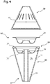
- FIG 4 a hookah tobacco bowl 30 is shown.
- this is designed as a hollow structure and has an outer wall 31 which delimits a receiving space 36 for a liquid, for example coolant.
- the receiving space 36 has a shell receptacle 34 into which a tobacco receiving shell 20 can be inserted.
- the tobacco receiving shell 20 is made of metal, for example, and can be removed and cleaned after the end of the smoking process.
- the shell receptacle 34 or its shell bottom 33 curves in the direction of the receiving space 36 inside the hookah tobacco bowl 30 and makes contact with the cooling liquid provided there.
- the use of the cooling liquid has the advantage that the tobacco remains cooled and does not burn until the coal inserted in the heat generator 10 has reached its operating temperature.
- the heat generator 10 is placed on the water pipe tobacco bowl 30 .
- the exemplary embodiment figure 4 embedded in the upper circumferential edge 38 of the hookah tobacco head 30 magnets 35 , preferably pressed, which hold the heat generator 10 made of metal on the hookah tobacco head 30 .
- Alternative embodiments not shown here provide a receiving groove or depression into which the heat generator or its lower edge can be inserted.
- the elements of the heat generator 10 have already been described above, so these elements will not be described again.
- At the lower end 37 of the water pipe tobacco head 30 tapers and can be used with this lower end 37 in a bottle and close it like a stopper.
- the hookah tobacco head 30 is shown in the embodiment as a one-piece element and consists of a silicone material. Of course, there is also the possibility that different materials are combined here, for example in a corresponding injection molding process.
- the water pipe tobacco head body 80 is hollow and, in the exemplary embodiment, carries the tobacco support part 90, which is additionally occupied here with a tobacco receiving shell 20 to be inserted into the shell receptacle 34.
Landscapes
- Thermotherapy And Cooling Therapy Devices (AREA)
- Manufacture Of Tobacco Products (AREA)
Description
- Die vorliegende Erfindung betrifft einen Wärmeerzeuger für Wasserpfeifen. Derartige Wärmeerzeuger finden vor allem in der Rauchgeräten wie beispielsweise Shishas Verwendung. Der Wärmeerzeuger wird dabei mit einer Wärmequelle, beispielsweise glühenden Kohlestücken befüllt. Ein unterhalb des Wärmeerzeugers angeordneter Tabak oder Tabakersatzstoff wird durch die vom Wärmeerzeuger abgegebene Hitze erhitzt und gibt dabei seine aromagebenden Inhaltsstoffe ab. Diese werden durch den Raucher anschließend konsumiert, zuvor jedoch durch ein mit Wasser gefülltes Gebinde gezogen. Das Dokument
US 2017/0265520 offenbart einen bekannten Wärmeerzeuger für Wasserpfeifen. - Bei den aus dem Stand der Technik bekannten Wärmeerzeugern hat es sich als nachteilig erwiesen, dass eine zufriedenstellende Regulierung der Wärmezufuhr nur über die Entnahme oder Zugabe von zusätzlichem Heizmaterial erfolgen kann. In einigen Fällen ist es wünschenswert, den Wärmeerzeugungsprozess im Verlauf des Auskühlens des Kohlenmaterials so zu regulieren, dass stets eine gleichmäßige Wärmeabgabe erfolgt. In anderen Fällen kann es sein, dass die Raucher eine starke Hitzeentwicklung wünschen, die durch eine sehr enge Heranführung der Wärmequelle an das Tabakmaterial erreicht wird. In jedem Fall bedarf die Regulierung der Temperatur eines unmittelbaren Eingriffs des Nutzers auf die Wärmequelle.
- Aufgabe der vorliegenden Erfindung ist es, einen Wärmeerzeuger zur Verfügung zu stellen, der eine einfache Regulierung der Wärmeabgabe ohne direkten Eingriff auf die Wärmequelle ermöglicht. Gleichzeitig befasst sich die Erfindung auch mit einem Wasserpfeifentabakkopf. Hierbei ist es eine Aufgabe der Erfindung einen kühlbaren oder gekühlten Kopf zur Verfügung zu stellen, der eine noch gleichmäßigere Aromaabgabe und langsame Verbrennung des Tabakmaterials oder eines Tabakersatzstoffes, insbesondere zu Beginn des Rauchprozesses ermöglicht.
- Die Aufgabe wird gelöst durch einen Wärmeerzeuger gemäß Anspruch 1.
- Bevorzugte Weiterbildungen sind Gegenstand der abhängigen Ansprüche. Der erfindungsgemäße Wärmeerzeuger für Wasserpfeifen ist als Gefäß ausgebildet, dass eine Umfangswand, einen Boden, ein Deckelteil, und einen im Innern des Wärmeerzeugers beweglich angeordneten Teller zur Aufnahme glühender Kohlen oder Kohlenersatzstoffen umfasst. Die erfindungsgemäße Aufgabe wird dadurch gelöst, dass in der Umfangswand des Wärmeerzeugers wenigstens ein Führungsschlitz angeordnet ist, der sich wendelartig zwischen dem Boden und dem Deckelteil erstreckt. Der Teller weist dabei wenigstens ein durch den Schlitz ragendes, im Schlitz geführtes Griffteil auf und kann in seiner Position stufenlos relativ zum Boden des Wärmeerzeugers verstellt werden. Diese Ausgestaltung erlaubt es, dass nach einmaligem Befüllen des Wärmeerzeugers mit Kohlenmaterial eine individuelle Regelung des Abstandes zwischen Kohlenmaterial und Boden des Wärmeerzeugers von außen erfolgt, und nach dem Befüllen kein unmittelbarer Eingriff auf das Kohlenmaterial mehr notwendig ist. Dies vermeidet unnötiges Öffnen des Wärmeerzeugers und verhindert zudem Verletzungen durch Verbrennung.
- Als vorteilhaft wird angesehen, wenn der Schlitz Rastpositionen für das Griffteil aufweist und sich das Griffteil im Innern des Schlitzes auf der Umfangswand abstützt. Hierdurch wird die Einstellung eines bevorzugten Abstandes zwischen Kohle und Boden möglich.
- Günstiger Weise weist der Boden eine sich in axialer Richtung des Wärmeerzeugers erstreckende Führung für den Teller auf, sodass einer eine stets gleichmäßige und sichere Bewegung des Tellers und dessen horizontale Lagerung möglich ist.
- In einer bevorzugten Ausführungsform ist vorgesehen, dass in der Umfangswand zwei sich gegenüberliegende, symmetrisch ausgebildete Schlitze vorgesehen sind und der Teller zwei Griffteile aufweist, wovon wenigstens eines den Schlitz durchragt und ein zweites in den Schlitz einsteht. Hierdurch wird die Führung des Tellers beim Verschieben im Wärmeerzeuger weiter verbessert. Auch in dieser Ausgestaltungsform wird es als günstig angesehen, wenn die Schlitze Rastpositionen für die Griffteile aufweisen.
- Die Belüftung der Kohle und damit der Verbrennungsprozess werden dadurch verbessert, dass der Teller in einer bevorzugten Ausgestaltungsform Löcher aufweist. In einer vorteilhaften Weiterbildung ist vorgesehen, dass der Teller einen umlaufenden Rand aufweist, der an der Umfangswand insbesondere dichtend anliegt.
- In einer Weiterbildung der Erfindung wird das Einlegen der Kohlen wesentlich vereinfacht, wenn der Teller eine zum Boden hin ausgerichtete Wölbung aufweist.
- Bevorzugt weist der Wärmeerzeuger eine kuppel-, kegel-, kegelstumpf-, pyramiden- oder halbkugelförmige Formgebung auf. Durch die geometrische Form, die nicht auf die vorgenannten beschränkt ist, wird eine optimale Zirkulation der Wärme im Innern des Wärmeerzeugers sichergestellt. Auch unter optischen Gesichtspunkten erweist sich eine Variation der Formgebung als besonders günstig.
- In einer Weiterbildung der Erfindung weist der Wärmeerzeuger eine Zugriffs- oder Befüllöffnung auf, durch die Brennmaterial in den Wärmeerzeuger eingeführt werden kann. In einer bevorzugten Ausführungsform zeichnet sich der Wärmeerzeuger dadurch aus, dass das Deckelteil abnehmbar ausgebildet ist. Alternativ oder zusätzlich hierzu wird es als günstig angesehen, wenn das Deckelteil wenigstens eine, insbesondere runde oder schlitz- oder langlochförmige Belüftungsöffnung aufweist. Als Alternative zu einer vollständigen Abnehmbarkeit kann auch vorgesehen werden, dass das Deckelteil relativ zum Körper des Wärmeerzeugers verschwenkt wird. Die Verschwenkung kann dabei in einer Ebene oder aus der Ebene heraus erfolgen.
- In einer besonders bevorzugten Ausgestaltung des Wärmeerzeugers ist im Deckelteil ein Schieber zum Öffnen und Schließen der wenigstens einen Belüftungsöffnung vorgesehen. Hierdurch wird zusätzlich zur Variation der Lage der Kohle im Innern des Wärmeerzeugers durch das Öffnen bzw. Schließen der Belüftungsöffnungen der Abbrandvorgang weiter beeinflusst und damit eine Hitzeentwicklung begünstigt oder verringert. Als vorteilhaft wird in diesem Zusammenhang angesehen, wenn Deckelteil und Schieber relativ zueinander und/oder gegenläufig zueinander verschiebbar angeordnet sind.
- In einer Weiterbildung der Erfindung ist vorgesehen, dass alternativ oder zusätzlich zu den Öffnungen im Deckelteil auch in der Umfangswand wenigstens eine, insbesondere runde oder schlitz- oder langlochförmige Belüftungsöffnung vorgesehen ist. Diese dient der Belüftung und somit der gleichmäßigeren Verbrennung des Materials.
- Um den Wärmeerzeuger besonders einfach auf eine Tabakkopf aufsetzen zu können, wird es als vorteilhaft angesehen, wenn der Wärmeerzeuger eine Grifflasche aufweist, die das einfache und vor allem verbrennungsfreie ergreifen des Wärmeerzeugers ermöglicht, auch wenn dieser bereits mit glühender Kohle befüllt ist. Günstiger Weise ist der Wärmeerzeuger aus Aluminium, Edelstahl oder einem hitzebeständigen Kunststoff gebildet und bevorzugt in einem Guss-, Druckguss-, Tiefzieh- , Schmiedeverfahren oder in einem spanabhebenden Verfahren hergestellt.
- Es wird auch ein Wasserpfeifentabakkopf, der nicht Bestandteil der vorliegenden Erfindung ist, beschrieben, welcher zum Aufsetzen eines Wärmeerzeugers wie zuvor beschrieben geeignet ist.
- Der Wasserpfeifentabakkopf hat dabei wenigstens einen Wasserpfeifentabakkopfkörper und einen Tabakauflageteil und ist dadurch gekennzeichnet, dass der Wasserpfeifentabakkopfkörper im Wesentlichen hohl ausgebildet ist.
- Diese hohle Ausgestaltung erlaubt eine Befüllung mit einer Flüssigkeit, beispielsweise mit Wasser oder einer Kühlflüssigkeit. Der gekühlte Wasserpfeifentabakkopf verhindert einen zu schnellen Abbrand des Tabakmaterials bei aufgesetzter Wärmequelle. Hierdurch wird eine gleichmäßige Aromaentwicklung und damit ein vorteilhaftes Raucherergebnis erzielt. Um die Flüssigkeit in den Hohlkörper einzuführen, weiß dieser bevorzugt eine Befüllöffnung auf.
- Da der Wasserpfeifentabakkopf mit starker Hitze beaufschlagt wird, wird es als günstig angesehen, wenn der gesamte Wasserpfeifentabakkopf oder nur der Wasserpfeifentabakkopfkörper und/oder der Tabakauflageteil ganz oder teilweise aus einem hitzebeständigen Material, insbesondere aus Silikon gefertigt ist/sind. Hierdurch werden herkömmliche Materialien, wie beispielsweise Stein, Keramik, Ton, Glas, Metall oder Porzellan ganz oder teilweise ersetzt und die Herstellung des Tabakkopfes wesentlich vereinfacht und vergünstigt.
- Als günstige Materialien für die Herstellung der nicht aus Silikon gefertigten Teile von Wasserpfeifentabakkopf, Tabakkopfkörper und/oder Tabakauflageteil werden Aluminium, Edelstahl oder ein anderer, hitzebeständiger Kunststoff angesehen. Wasserpfeifentabakkopfkörper und/oder der Tabakauflageteil werden bevorzugt in einem Guss-, Druckguss-, Tiefzieh-, Blasform-, oder Schmiedeverfahren oder in einem spanabhebenden Verfahren hergestellt, wobei sich das angewandte Verfahren nach dem Material, den Materialeigenschaften sowie der Bearbeitbarkeit richtet.
- Es ist vorgesehen, dass der Wasserpfeifentabakkopfkörper und/oder der Tabakauflageteil aus unterschiedlichen Materialen gebildet sind und eine lösbare oder feste Verbindung von Wasserpfeifentabakkopfkörper und Tabakauflageteil vorgesehen ist. Die lösbare Verbindung kann beispielsweise als Schraub- oder Steckverbindung ausgebildet sein. Eine unlösbare Verbindung wird dadurch hergestellt, dass die beiden Teile miteinander verschmolzen oder verklebt sind.
- Als vorteilhafte Weiterbildung erweist es sich, wenn das Tabakauflageteil mulden- oder schalenförmig ausgebildet und in einen Hohlraum des Wasserpfeifentabakkopfkörpers eingesenkt ist. Hierdurch wird eine weitere Verbesserung der Kühleigenschaften und -leistungen erzielt.
- Es wird als eine günstige Ausführungsform angesehen, wenn der Wasserpfeifentabakkopfkörper ganz oder teilweise mit Flüssigkeit, insbesondere einer Kühlflüssigkeit befüllbar ist. In diesem Zusammenhang vorteilhaft erweist sich, wenn die die Befüllöffnung wiederverschließbar ausgebildet ist. Somit kann eine Nachfüllung oder ein Austausch des Kühlmittels nach Benutzung erfolgen.
- Die Kühlung des Tabaks wird weiter verbessert, wenn die dem Hohlraum zugewandte Oberfläche des Tabakauflageteils die Flüssigkeit kontaktiert.
- Der Wasserpfeifentabakkopf ist dafür vorgesehen, dass auf ihm ein Wärmeerzeuger, beispielsweise wie eingangs beschrieben aufgesetzt wird. Um eine sichere Verbindung zwischen Wärmeerzeuger und Wasserpfeifentabakkopf zu erreichen, weist Letzterer bevorzugt eine Aufnahme, insbesondere Einsatznut oder - vertiefung für die spielarme Verbindung mit dem Wärmeerzeuger auf. In einer vorteilhaften Weiterbildung können alternativ oder zusätzlich Mittel zur Ausbildung einer lösbaren Verbindung von Wärmeerzeuger und/oder Wasserpfeifentabakkopf vorgesehen werden. In diesem Zusammenhang wird es als günstig angesehen, wenn diese Mittel als miteinander in Eingriff bringbare Rastaufnahmen, Schraub-, Steck- oder als Magnetverbinder ausgebildet sind.
- In den Zeichnungen Ausführungsformen der Erfindung mehreren Darstellungen gezeigt. Es zeigt:
- Fig. 1
- eine Wasserpfeife in perspektivischer Darstellung,
- Fig. 2a
- einen Wärmeerzeuger in perspektivischer Darstellung,
- Fig. 2b
- einen Wärmeerzeuger aus
Figur 2a in Schnittdarstellung, - Fig. 3
- eine weitere Ausführungsform eines erfindungsgemäßen Wärmeerzeuger in perspektivischer Darstellung, und
- Fig. 4
- einer Ausführungsform des Wasserpfeifentabakkopfes in Explosionsdarstellung.
-
Figur 1 zeigt eine herkömmliche Wasserpfeife 1, die auch unter dem Begriff Shisha bekannt ist. Diese weist im Ausführungsbeispiel mehrere Teile auf. So verfügt die hier dargestellte Wasserpfeife 1 über ein mit Wasser befülltes Gefäß 60, das den unteren Teil 40 der Wasserpfeife 1 bildet. Hier ist auch die Anschlussöffnung 50 für den inFigur 1 nicht dargestellten Rauchschlauch vorgesehen. Im Inneren des Gefäßes 60 sind entsprechende Röhrchen für die Rauchleitung vorgesehen. Der obere Teil 70 der Wasserpfeife 1 wird gebildet durch einen Ascheteller 71 an den sich der Wasserpfeifentabakkopf 30 anschließt. Im Ausführungsbeispiel weist der Wasserpfeifentabakkopf 30 zusätzlich eine Tabakaufnahmeschale 20 auf, auf der Tabak aufgelegt werden kann. Abgeschlossen wird das System durch einen auf dem Wasserpfeifentabakkopf 30 absetzbaren Wärmeerzeuger 10. Die beiden letztgenannten Elemente werden in den nachfolgenden Zeichnungen ausführlich beschrieben. -
Figur 2a zeigt einen Wärmeerzeuger 10 in perspektivischer Darstellung. Dieser weist hier einen halbkugelförmigen Deckel 11 auf, der mit Belüftungsöffnungen 110 versehen ist. Am Deckel 11 angeformt ist ein Griffvorsprung 121 der zum Verschwenken des Deckels 11 und öffnen des Wärmeerzeugers 10 Verwendung findet. Alternativ zur hier dargestellten Ausführungsform mit in der Ebene verschwenktem Deckel 11 kann dieser auch als Klappdeckel ausgebildet werden. Dieser Ausführungsform ist hier nicht dargestellt. Der Wärmeerzeuger 10 weist ferner eine Umfangswand 13 auf, die im Ausführungsbeispiel mit einem wendelartig umlaufenden, in der Umfangswand 13 eingebrachten Schlitz 14 versehen ist. Der Schlitz 14 dient als Führung für das Griffteil 16, das an dem im Inneren des Wärmeerzeugers 10 angeordneten Teller 120 befestigt ist. - Der Schlitz 14 weist im Ausführungsbeispiel Rastpositionen 17 auf, in die das Griffteil 16 eingesenkt werden kann. Es kann somit eine nahezu stufenlose Verstellung des Tellers 120 im Innern des Wärmeerzeugers 10 vorgenommen werden.
- Die Umfangswand 13 weist im hier dargestellten Ausführungsbeispiel Belüftungslöcher 19 auf. Auch ist zwischen dem Boden 18 und dem Deckel 11 etwa mittig in der Umfangswand 13 eine Grifflasche 15 vorgesehen. Über diese kann der Wärmeerzeuger 10 angehoben und beispielsweise auf einen Wasserpfeifentabakkopf 30 aufgesetzt werden.
-
Figur 2b zeigt den Zusammenhang mitFigur 2a beschriebenen Wärmeerzeugers 10 in Schnittdarstellung. Gut erkennbar ist hier der im Innern des Wärmeerzeugers 10 angeordnete Teller 120, der beim Betrieb der Wasserpfeife 1 als Auflage für Kohlen dient. Am Teller 120 angeordnet ist das Griffteil 16, dass sich durch die Umfangswand 13 und den darin angeordneten Schlitz 14 nach außen erstreckt. Über das Griffteil 16 kann die Position des Tellers 120 im Innern des Wärmeerzeugers 10 verändert werden, indem das Griffteil 16 entlang des in der Umfangswand 13 vorgesehenen Schlitzes 14 verschoben wird. Hierbei ändert sich dann der Abstand zwischen Teller 120 und darauf aufgelegter glühender Kohle (nicht dargestellt) und Boden 18 des Wärmeerzeugers 10. Um eine gleichmäßige Führung und stets horizontale Lage des Tellers 120 zu gewährleisten, ist im Innern des Wärmeerzeuger 10 ein sich zwischen dem Boden 18 und dem Deckel 11 erstreckender Führungsstab 122 vorgesehen, entlang dem der Teller 120 axial verschoben werden kann. - Der Deckel 11 weist einen Schieber 113 auf, der relativ zum Deckel 11 verschiebbar ist und die Belüftungsöffnungen 110 im Deckel 11 verschließt oder freigibt. Die Belüftungslöcher 19 in der Umfangswand 13 sind immer geöffnet und erlauben das Eintreten von Luft, was den Glühvorgang positiv beeinflusst.
-
Figur 3 zeigt eine weitere Ausführungsform des Wärmeerzeugers 10. Dieser weist ebenfalls einen Schlitz 14 in der Umfangswand 13 auf, in dem ein Griffteil 16 des im Innern angeordneten Tellers 120 verschoben werden kann. Gut erkennbar sind in diesem Ausführungsbeispiel die Rastpositionen 17, in die das Griffteil 16 eingelegt werden kann. - Der Wärmeerzeuger 10 der
Figur 3 verfügt ebenfalls über einen Deckel 11 in dem Belüftungsöffnungen 110 vorgesehen sind. Diese sind schlitzförmig ausgebildet. Eine Regulierung der Öffnungsweite ist hier nicht vorgesehen, weshalb kein Schieber eingebaut ist. Der hier dargestellte Deckel 11 ist nicht verschwenkbar sondern wird aufgeklappt. Hierzu dient der Griffvorsprung 121, der sich mit der Griffflasche 15 am Umfang 13 deckt. Neben der in den Ausführungsbeispielen dargestellten kegelstumpf- und kugelförmigen Ausgestaltungen kann selbstverständlich jede weitere günstig erscheinende und unter optischen Aspekten gewünschte Ausgestaltung des Deckels 11 gewählt werden. - In
Figur 4 ist einer Wasserpfeifentabakkopf 30 dargestellt. - Dieser ist im Ausführungsbeispiel als hohles Gebilde ausgebildet und weist eine Außenwand 31 auf, die einen Aufnahmeraum 36 für eine Flüssigkeit, beispielsweise Kühlmittel, begrenzt. Am oberen Ende 39 weist der Aufnahmeraum 36 eine Schalenaufnahme 34 auf, in die eine Tabakaufnahmeschale 20 eingesetzt werden kann. Die Tabakaufnahmeschale 20 ist beispielsweise aus Metall hergestellt und kann nach Ende des Rauchprozesses entnommen und gereinigt werden. Die Schalenaufnahme 34 bzw. deren Schalenboden 33 wölbt sich in Richtung des Aufnahmeraums 36 im Inneren des Wasserpfeifentabakkopfes 30 und kontaktiert die dort vorgesehene Kühlflüssigkeit. Die Verwendung der Kühlflüssigkeit hat den Vorteil, dass der Tabak so lange gekühlt bleibt und nicht verbrennt, bis die in dem Wärmeerzeuger 10 eingelegte Kohle ihre Betriebstemperatur erreicht hat.
- Zur Inbetriebnahme der Wasserpfeife 1 wird der Wärmeerzeuger 10 auf dem Wasserpfeifentabakkopf 30 aufgesetzt. Um eine gute Verbindung zu erreichen, sind im Ausführungsbeispiel der
Figur 4 im oberen umlaufenden Rand 38 des Wasserpfeifentabakkopf 30 Magnete 35 eingelassen, bevorzugt eingepresst, die den aus Metall bestehenden Wärmeerzeuger 10 auf dem Wasserpfeifentabakkopf 30 halten. Alternative, hier nicht dargestellte Ausführungsformen sehen eine Aufnahmenut oder Vertiefung vor, in die der Wärmeerzeuger oder dessen unterer Rand eingesetzt werden kann. Die Elemente des Wärmeerzeugers 10 wurden bereits zuvor beschrieben, es wird daher auf eine erneute Beschreibung dieser Elemente verzichtet. Am unteren Ende 37 läuft der Wasserpfeifentabakkopf 30 konisch zu und kann mit diesem unteren Ende 37 in eine Flasche eingesetzt werden und diese nach Art eines Stopfens verschließen. Im Inneren des Wasserpfeifentabakkopfes 30 ist ein Führungsrohr 32 für den entstehenden Rauch vorgesehen. Der Wasserpfeifentabakkopf 30 ist im Ausführungsbeispiel als einstückiges Element dargestellt und besteht aus einem Silikonmaterial. Selbstverständlich besteht auch die Möglichkeit, dass hier unterschiedliche Materialien kombiniert werden, beispielsweise in einem entsprechenden Spritzgussverfahren. In jedem Fall ist der Wasserpfeifentabakkopfkörper 80 hohl ausgebildet und trägt im Ausführungsbeispiel das Tabakauflageteil 90, das hier zusätzliche mit einer in die Schalenaufnahme 34 einzusetzenden Tabakaufnahmeschale 20 belegt wird. -
1 = Wasserpfeife 30 = Wasserpfeifentabakkopf 10 = Wärmeerzeuger 31 = Außenwand 11 = Deckel 32 = Führungsrohr 110 = Belüftungsöffnung 33 = Schalenboden 120 = Teller 34 = Schalenaufnahme 121 = Griffvorsprung 35 = Magnet 122 = Führungsstab 36 = Aufnahmeraum 113 = Schieber 37 = Ende 13 = Umfangswand 38 = umlaufenden Rand 14 = Schlitz 39 = oberes Ende 15 = Grifflasche 40 = unterer Teil 16 = Griffteil 50 = Anschlussöffnung 17 = Rastpositionen 60 = Gefäß 18 = Boden 70 = oberer Teil 19 = Belüftungslöcher 71 = Ascheteller 20 = Tabakaufnahmeschale 90 = Tabakauflageteil
Claims (15)
- Wärmeerzeuger (10) für Wasserpfeifen (1) umfassend:- eine Umfangswand (13),- einen Boden (18),- ein Deckelteil (11), und- einen im Innern des Wärmeerzeugers (10) beweglich angeordneten Teller (120) zur Aufnahme glühender Kohlen oder Kohlenersatzstoffen,dadurch gekennzeichnet, dass in der Umfangswand (13) des Wärmeerzeugers (10) wenigstens ein Schlitz (14) angeordnet ist, der sich wendelartig zwischen dem Boden (18) und dem Deckelteil (11) erstreckt und der Teller (120) wenigstens ein durch den Schlitz (14) ragendes, im Schlitz (14) geführtes Griffteil (16) aufweist und eine stufenlose Verstellbarkeit des Tellers (120) relativ zum Boden (18) vorgesehen ist.
- Wärmeerzeuger (10) nach Anspruch 1, dadurch gekennzeichnet, dass der Schlitz (14) Rastpositionen für das Griffteil (16) aufweist und sich das Griffteil (16) im Innern des Schlitzes (14) auf der Umfangswand abstützt.
- Wärmeerzeuger (10) nach Anspruch 1 oder 2, dadurch gekennzeichnet, dass der Boden (18) eine sich in axialer Richtung des Wärmeerzeugers (10) erstreckende Führung für den Teller (120) aufweist.
- Wärmeerzeuger (10) nach Anspruch nach einem der vorhergehenden Ansprüche, dadurch gekennzeichnet, dass in der Umfangswand (13) zwei sich gegenüberliegende, symmetrisch ausgebildete Schlitze (14) vorgesehen sind und der Teller (120) zwei Griffteile aufweist, wovon wenigstens eines den Schlitz (14) durchragt und ein zweites in den Schlitz (14) einsteht, wobei die Schlitze (14) insbesondere Rastpositionen (17) für die Griffteile (16) aufweisen.
- Wärmeerzeuger (10) nach einem der vorhergehenden Ansprüche, dadurch gekennzeichnet, dass der Teller (120) Löcher aufweist und/oder der Teller (120) einen umlaufenden Rand aufweist, der an der Umfangswand (13) insbesondere dichtend anliegt.
- Wärmeerzeuger (10) nach einem der vorhergehenden Ansprüche, dadurch gekennzeichnet, dass der Teller (120) eine zum Boden (18) hin ausgerichtete Wölbung aufweist.
- Wärmeerzeuger (10) nach einem der vorhergehenden Ansprüche, gekennzeichnet, durch eine kuppel-, kegel-, kegelstumpf-, pyramiden- oder halbkugelförmige Formgebung.
- Wärmeerzeuger (10) nach einem der vorhergehenden Ansprüche, dadurch gekennzeichnet, dass der Wärmeerzeuger (10) eine Zugriffs- oder Befüllöffnung aufweist.
- Wärmeerzeuger (10) nach einem der vorhergehenden Ansprüche, dadurch gekennzeichnet, dass das Deckelteil (11) abnehmbar ausgebildet ist.
- Wärmeerzeuger (10) nach einem der vorhergehenden Ansprüche, dadurch gekennzeichnet, dass das Deckelteil (11) wenigstens eine, insbesondere runde oder schlitz- oder langlochförmige Belüftungsöffnung (110) aufweist.
- Wärmeerzeuger (10) nach Anspruch 10, dadurch gekennzeichnet, dass im Deckelteil (11) ein Schieber (113) zum Öffnen und Schließen der wenigstens einen Belüftungsöffnung (110) vorgesehen ist.
- Wärmeerzeuger (10) nach Anspruch 11, dadurch gekennzeichnet, dass Deckelteil (11) und Schieber (113) relativ zueinander und/oder gegenläufig zueinander verschiebbar angeordnet sind.
- Wärmeerzeuger (10) nach einem der vorhergehenden Ansprüche, dadurch gekennzeichnet, dass in der Umfangswand (13) wenigstens eine, insbesondere runde oder schlitz- oder langlochförmige Belüftungsöffnung (110) vorgesehen ist.
- Wärmeerzeuger (10) nach einem der vorhergehenden Ansprüche, dadurch gekennzeichnet, dass der Wärmeerzeuger (10) einen Griff (15) oder eine Grifflasche (121) aufweist.
- Wärmeerzeuger (10) nach einem der vorhergehenden Ansprüche, dadurch gekennzeichnet, dass der Wärmeerzeuger (10) aus Aluminium, Edelstahl oder einem hitzebeständigen Kunststoff gebildet ist und/oder der Wärmeerzeuger (10) bevorzugt in einem Guss-, Druckguss-, Tiefzieh-, Schmiedeverfahren oder in einem spanabhebenden Verfahren hergestellt ist.
Applications Claiming Priority (2)
| Application Number | Priority Date | Filing Date | Title |
|---|---|---|---|
| DE202018102820.0U DE202018102820U1 (de) | 2018-05-21 | 2018-05-21 | Wärmeerzeuger für Wasserpfeifen und Wasserpfeifentabakkopf |
| PCT/EP2019/062749 WO2019224112A1 (de) | 2018-05-21 | 2019-05-16 | Wärmeerzeuger für wasserpfeifen und wasserpfeifentabakkopf |
Publications (2)
| Publication Number | Publication Date |
|---|---|
| EP3796792A1 EP3796792A1 (de) | 2021-03-31 |
| EP3796792B1 true EP3796792B1 (de) | 2022-09-07 |
Family
ID=62716700
Family Applications (1)
| Application Number | Title | Priority Date | Filing Date |
|---|---|---|---|
| EP19726930.1A Active EP3796792B1 (de) | 2018-05-21 | 2019-05-16 | Wärmeerzeuger für wasserpfeifen |
Country Status (6)
| Country | Link |
|---|---|
| US (1) | US20210360964A1 (de) |
| EP (1) | EP3796792B1 (de) |
| CA (1) | CA3100411A1 (de) |
| DE (1) | DE202018102820U1 (de) |
| MA (1) | MA52705A (de) |
| WO (1) | WO2019224112A1 (de) |
Families Citing this family (17)
| Publication number | Priority date | Publication date | Assignee | Title |
|---|---|---|---|---|
| AT521348B1 (de) * | 2018-08-16 | 2020-01-15 | Grgs Fahim | Wasserpfeifenkopf |
| DE102018123218A1 (de) * | 2018-09-20 | 2020-03-26 | Alaa El Din Kotb | Pfeifenkopf für eine Wasserpfeife |
| DE202018106465U1 (de) * | 2018-11-14 | 2020-02-17 | Hisham Omayrat | Wasserpfeife mit abnehmbarem Boden sowie drehbarer Kohleaufbewahrung |
| DE202019001162U1 (de) * | 2019-03-12 | 2020-06-19 | Florian Bartel | Kamin für eine Wasserpfeife |
| DE102019125344B3 (de) * | 2019-09-20 | 2021-01-21 | Shisha Cloud GmbH | Kaminaufsatz für einen Wasserpfeifenkopf |
| ES2972465T3 (es) * | 2019-12-02 | 2024-06-12 | Philip Morris Products Sa | Dispositivo de narguile con canales |
| FR3104001B1 (fr) * | 2019-12-05 | 2021-11-26 | Royal Distrib T D N | Dispositif de gestion de la chaleur pour appareil à fumer de type pipe à eau |
| DE102020101664A1 (de) * | 2020-01-24 | 2021-07-29 | Blue Horse GmbH | Kohleaufsatz einer Wasserpfeife |
| US20220264941A1 (en) * | 2021-02-12 | 2022-08-25 | David Zoumut | Heat and airflow regulation smoking bowl |
| RU2751626C1 (ru) * | 2021-02-15 | 2021-07-15 | Эльмар Рашид оглы Алиев | Контейнер для кальяна с предварительно упакованной курительной смесью |
| US12121074B2 (en) * | 2021-07-01 | 2024-10-22 | Kiraco Llc | Tobacco bowl |
| US11497241B1 (en) * | 2021-07-15 | 2022-11-15 | Kaloud, Inc. | Assembly and insert for evenly heating a smokable substance |
| US20230012493A1 (en) * | 2021-07-15 | 2023-01-19 | Kaloud, Inc. | Assembly and insert for evenly heating a smokable substance |
| DE102022107121B3 (de) * | 2022-03-25 | 2023-03-16 | Andreas Richard Bayer | Kaminaufsatz mit verbessertem Halt auf einem Kopf einer Shisha |
| US20240114954A1 (en) * | 2022-10-10 | 2024-04-11 | Alco Innovations, LLC | Smoking device |
| DE102024116480A1 (de) | 2024-06-12 | 2025-12-18 | Hamdi Cem Bozkurt | Wasserpfeifenkopf, Wasserpfeife und Verfahren zum Betreiben derselben |
| DE202024103440U1 (de) | 2024-06-12 | 2024-10-28 | Hamdi Cem Bozkurt | Wasserpfeifenkopf, Wasserpfeife und Heizmittel zum Betreiben derselben |
Family Cites Families (18)
| Publication number | Priority date | Publication date | Assignee | Title |
|---|---|---|---|---|
| US4036240A (en) * | 1974-12-16 | 1977-07-19 | Murray Jr Joseph E | Smoking apparatus with replaceable filtering cartridge |
| JPS6310719Y2 (de) * | 1985-06-26 | 1988-03-30 | ||
| FR2871344B1 (fr) * | 2004-06-10 | 2007-01-05 | Shishamania Internat Sarl | Narguille a allumage simplifie |
| ES2480492T3 (es) * | 2008-10-24 | 2014-07-28 | Pflaum, Andre | Porción de tabaco para Narguile |
| US20100101590A1 (en) * | 2008-10-24 | 2010-04-29 | Andre Pflaum | Hookah tobacco portion |
| US20100212679A1 (en) * | 2009-02-26 | 2010-08-26 | Edwar Bishara | Electric heating for hookah |
| US8983282B2 (en) * | 2009-02-26 | 2015-03-17 | Edwar Bishara | Electric heater for hookah |
| US9237770B2 (en) * | 2012-06-06 | 2016-01-19 | Kaloud, Inc. | Hookah heat management accessory |
| DE202013101208U1 (de) * | 2013-03-21 | 2013-03-27 | Ibrahim Dabes | Wasserpfeife mit einem Behälter und einem Verteilerstück |
| US20190350253A1 (en) * | 2014-11-20 | 2019-11-21 | Kaloud, Inc. | Heat management accessory for hookah |
| US10925312B2 (en) * | 2017-02-01 | 2021-02-23 | Kaloud, Inc. | Systems, methods, and devices for heat management of heating implements for water pipes |
| US10561172B2 (en) * | 2016-03-07 | 2020-02-18 | Wallbrooke Investments Ltd. | Inductive heating apparatus and related method |
| US20170265520A1 (en) * | 2016-03-21 | 2017-09-21 | Tyler Chi Do | Fliptech Hookah Bowl System and Uses Thereof |
| US11206866B2 (en) * | 2017-11-09 | 2021-12-28 | Starbuzz Tobacco, Inc. | Hookahs, heating units, and related methods |
| US11213067B2 (en) * | 2018-04-23 | 2022-01-04 | Starbuzz Tobacco, Inc. | Hookahs, heating units, and related methods |
| DE202019100556U1 (de) * | 2019-01-30 | 2019-02-06 | Schmidt Innovations GmbH | Wärmeregulationssystem für eine Wasserpfeife |
| US11832651B2 (en) * | 2020-12-16 | 2023-12-05 | Flume Sarl | Hookah bowl thermal vaporizer |
| US11497241B1 (en) * | 2021-07-15 | 2022-11-15 | Kaloud, Inc. | Assembly and insert for evenly heating a smokable substance |
-
2018
- 2018-05-21 DE DE202018102820.0U patent/DE202018102820U1/de not_active Expired - Lifetime
-
2019
- 2019-05-16 EP EP19726930.1A patent/EP3796792B1/de active Active
- 2019-05-16 CA CA3100411A patent/CA3100411A1/en active Pending
- 2019-05-16 WO PCT/EP2019/062749 patent/WO2019224112A1/de not_active Ceased
- 2019-05-16 US US17/057,954 patent/US20210360964A1/en not_active Abandoned
- 2019-05-16 MA MA052705A patent/MA52705A/fr unknown
Also Published As
| Publication number | Publication date |
|---|---|
| WO2019224112A1 (de) | 2019-11-28 |
| CA3100411A1 (en) | 2019-11-28 |
| EP3796792A1 (de) | 2021-03-31 |
| DE202018102820U1 (de) | 2018-06-12 |
| US20210360964A1 (en) | 2021-11-25 |
| MA52705A (fr) | 2021-04-14 |
Similar Documents
| Publication | Publication Date | Title |
|---|---|---|
| EP3796792B1 (de) | Wärmeerzeuger für wasserpfeifen | |
| DE102015106787A1 (de) | Rauchgerät für HNB-Rauchartikel und Verfahren zur Herstellung einer HNB-Rauchvorrichtung | |
| EP0130351B1 (de) | Instrument zur indirekten Behandlung mit Wärme und Moxarauch | |
| DE202021102986U1 (de) | Tabakaufnahmeteil und mit einem Tabakaufnahmeteil ausgestattete Wasserpfeife | |
| DE202020100701U1 (de) | Wasserpfeife und Wasserpfeifenzubehör | |
| DE4013359C2 (de) | ||
| DE20307130U1 (de) | Aschesammler für Raucher | |
| DE102010020012A1 (de) | Vorrichtung zum Anzünden und Vorglühen von Brennmitteln, insbesondere Grillkohle oder Grillbriketts | |
| DE9411524U1 (de) | Grillgerät | |
| EP4248767B1 (de) | Kaminaufsatz mit verbessertem halt auf einem kopf einer shisha | |
| DE4306845A1 (de) | Elektro-Tischgrill mit integrierter Öko-Grillpfanne bzw. Öko-Grillrost | |
| DE4337397C1 (de) | Kerzenträger | |
| DE663350C (de) | Heizeinrichtung fuer Konservendosen | |
| DE202019107006U1 (de) | Einrichtung zum Abbrennen von Räucherkegeln | |
| CH353211A (de) | Einspritzdüse für Brennkraftmaschinen | |
| DE202022102482U1 (de) | Tabakkopf für eine Wasserpfeife | |
| DE1457520A1 (de) | Elektrischer Zigarrenanzuender | |
| DE2053527C3 (de) | Kerzenlaufrohr | |
| DE102024116480A1 (de) | Wasserpfeifenkopf, Wasserpfeife und Verfahren zum Betreiben derselben | |
| DE202024103440U1 (de) | Wasserpfeifenkopf, Wasserpfeife und Heizmittel zum Betreiben derselben | |
| DE401915C (de) | Heizvorrichtung nach Art der Saegespaeneoefen mit um einen Luftkanal herum aufgeschichtetem Brennkoerper | |
| AT224306B (de) | Regelbare Heizeinrichtung bei Petrolgasgeräten | |
| DE179134A (de) | ||
| DE645187C (de) | Gaserzeuger mit waermespeichernder Ausfuetterung | |
| DE102017008085B3 (de) | Aufsatzelement für den Kopf einer Wasserpfeife |
Legal Events
| Date | Code | Title | Description |
|---|---|---|---|
| STAA | Information on the status of an ep patent application or granted ep patent |
Free format text: STATUS: THE INTERNATIONAL PUBLICATION HAS BEEN MADE |
|
| PUAI | Public reference made under article 153(3) epc to a published international application that has entered the european phase |
Free format text: ORIGINAL CODE: 0009012 |
|
| STAA | Information on the status of an ep patent application or granted ep patent |
Free format text: STATUS: REQUEST FOR EXAMINATION WAS MADE |
|
| 17P | Request for examination filed |
Effective date: 20201218 |
|
| AK | Designated contracting states |
Kind code of ref document: A1 Designated state(s): AL AT BE BG CH CY CZ DE DK EE ES FI FR GB GR HR HU IE IS IT LI LT LU LV MC MK MT NL NO PL PT RO RS SE SI SK SM TR |
|
| AX | Request for extension of the european patent |
Extension state: BA ME |
|
| RIN1 | Information on inventor provided before grant (corrected) |
Inventor name: BOZKURT, CEM HAMDI |
|
| DAX | Request for extension of the european patent (deleted) | ||
| RAV | Requested validation state of the european patent: fee paid |
Extension state: MA Effective date: 20201218 Extension state: TN Effective date: 20201218 |
|
| GRAP | Despatch of communication of intention to grant a patent |
Free format text: ORIGINAL CODE: EPIDOSNIGR1 |
|
| STAA | Information on the status of an ep patent application or granted ep patent |
Free format text: STATUS: GRANT OF PATENT IS INTENDED |
|
| INTG | Intention to grant announced |
Effective date: 20220412 |
|
| GRAS | Grant fee paid |
Free format text: ORIGINAL CODE: EPIDOSNIGR3 |
|
| GRAA | (expected) grant |
Free format text: ORIGINAL CODE: 0009210 |
|
| STAA | Information on the status of an ep patent application or granted ep patent |
Free format text: STATUS: THE PATENT HAS BEEN GRANTED |
|
| AK | Designated contracting states |
Kind code of ref document: B1 Designated state(s): AL AT BE BG CH CY CZ DE DK EE ES FI FR GB GR HR HU IE IS IT LI LT LU LV MC MK MT NL NO PL PT RO RS SE SI SK SM TR |
|
| REG | Reference to a national code |
Ref country code: GB Ref legal event code: FG4D Free format text: NOT ENGLISH |
|
| REG | Reference to a national code |
Ref country code: CH Ref legal event code: EP Ref country code: AT Ref legal event code: REF Ref document number: 1516320 Country of ref document: AT Kind code of ref document: T Effective date: 20220915 |
|
| REG | Reference to a national code |
Ref country code: DE Ref legal event code: R096 Ref document number: 502019005576 Country of ref document: DE |
|
| REG | Reference to a national code |
Ref country code: IE Ref legal event code: FG4D Free format text: LANGUAGE OF EP DOCUMENT: GERMAN |
|
| REG | Reference to a national code |
Ref country code: LT Ref legal event code: MG9D |
|
| REG | Reference to a national code |
Ref country code: NL Ref legal event code: MP Effective date: 20220907 |
|
| PG25 | Lapsed in a contracting state [announced via postgrant information from national office to epo] |
Ref country code: SE Free format text: LAPSE BECAUSE OF FAILURE TO SUBMIT A TRANSLATION OF THE DESCRIPTION OR TO PAY THE FEE WITHIN THE PRESCRIBED TIME-LIMIT Effective date: 20220907 Ref country code: RS Free format text: LAPSE BECAUSE OF FAILURE TO SUBMIT A TRANSLATION OF THE DESCRIPTION OR TO PAY THE FEE WITHIN THE PRESCRIBED TIME-LIMIT Effective date: 20220907 Ref country code: NO Free format text: LAPSE BECAUSE OF FAILURE TO SUBMIT A TRANSLATION OF THE DESCRIPTION OR TO PAY THE FEE WITHIN THE PRESCRIBED TIME-LIMIT Effective date: 20221207 Ref country code: LV Free format text: LAPSE BECAUSE OF FAILURE TO SUBMIT A TRANSLATION OF THE DESCRIPTION OR TO PAY THE FEE WITHIN THE PRESCRIBED TIME-LIMIT Effective date: 20220907 Ref country code: LT Free format text: LAPSE BECAUSE OF FAILURE TO SUBMIT A TRANSLATION OF THE DESCRIPTION OR TO PAY THE FEE WITHIN THE PRESCRIBED TIME-LIMIT Effective date: 20220907 Ref country code: FI Free format text: LAPSE BECAUSE OF FAILURE TO SUBMIT A TRANSLATION OF THE DESCRIPTION OR TO PAY THE FEE WITHIN THE PRESCRIBED TIME-LIMIT Effective date: 20220907 |
|
| PG25 | Lapsed in a contracting state [announced via postgrant information from national office to epo] |
Ref country code: HR Free format text: LAPSE BECAUSE OF FAILURE TO SUBMIT A TRANSLATION OF THE DESCRIPTION OR TO PAY THE FEE WITHIN THE PRESCRIBED TIME-LIMIT Effective date: 20220907 Ref country code: GR Free format text: LAPSE BECAUSE OF FAILURE TO SUBMIT A TRANSLATION OF THE DESCRIPTION OR TO PAY THE FEE WITHIN THE PRESCRIBED TIME-LIMIT Effective date: 20221208 |
|
| PG25 | Lapsed in a contracting state [announced via postgrant information from national office to epo] |
Ref country code: SM Free format text: LAPSE BECAUSE OF FAILURE TO SUBMIT A TRANSLATION OF THE DESCRIPTION OR TO PAY THE FEE WITHIN THE PRESCRIBED TIME-LIMIT Effective date: 20220907 Ref country code: RO Free format text: LAPSE BECAUSE OF FAILURE TO SUBMIT A TRANSLATION OF THE DESCRIPTION OR TO PAY THE FEE WITHIN THE PRESCRIBED TIME-LIMIT Effective date: 20220907 Ref country code: PT Free format text: LAPSE BECAUSE OF FAILURE TO SUBMIT A TRANSLATION OF THE DESCRIPTION OR TO PAY THE FEE WITHIN THE PRESCRIBED TIME-LIMIT Effective date: 20230109 Ref country code: ES Free format text: LAPSE BECAUSE OF FAILURE TO SUBMIT A TRANSLATION OF THE DESCRIPTION OR TO PAY THE FEE WITHIN THE PRESCRIBED TIME-LIMIT Effective date: 20220907 Ref country code: CZ Free format text: LAPSE BECAUSE OF FAILURE TO SUBMIT A TRANSLATION OF THE DESCRIPTION OR TO PAY THE FEE WITHIN THE PRESCRIBED TIME-LIMIT Effective date: 20220907 |
|
| PG25 | Lapsed in a contracting state [announced via postgrant information from national office to epo] |
Ref country code: SK Free format text: LAPSE BECAUSE OF FAILURE TO SUBMIT A TRANSLATION OF THE DESCRIPTION OR TO PAY THE FEE WITHIN THE PRESCRIBED TIME-LIMIT Effective date: 20220907 Ref country code: PL Free format text: LAPSE BECAUSE OF FAILURE TO SUBMIT A TRANSLATION OF THE DESCRIPTION OR TO PAY THE FEE WITHIN THE PRESCRIBED TIME-LIMIT Effective date: 20220907 Ref country code: IS Free format text: LAPSE BECAUSE OF FAILURE TO SUBMIT A TRANSLATION OF THE DESCRIPTION OR TO PAY THE FEE WITHIN THE PRESCRIBED TIME-LIMIT Effective date: 20230107 Ref country code: EE Free format text: LAPSE BECAUSE OF FAILURE TO SUBMIT A TRANSLATION OF THE DESCRIPTION OR TO PAY THE FEE WITHIN THE PRESCRIBED TIME-LIMIT Effective date: 20220907 |
|
| REG | Reference to a national code |
Ref country code: DE Ref legal event code: R097 Ref document number: 502019005576 Country of ref document: DE |
|
| PG25 | Lapsed in a contracting state [announced via postgrant information from national office to epo] |
Ref country code: NL Free format text: LAPSE BECAUSE OF FAILURE TO SUBMIT A TRANSLATION OF THE DESCRIPTION OR TO PAY THE FEE WITHIN THE PRESCRIBED TIME-LIMIT Effective date: 20220907 Ref country code: AL Free format text: LAPSE BECAUSE OF FAILURE TO SUBMIT A TRANSLATION OF THE DESCRIPTION OR TO PAY THE FEE WITHIN THE PRESCRIBED TIME-LIMIT Effective date: 20220907 |
|
| PLBE | No opposition filed within time limit |
Free format text: ORIGINAL CODE: 0009261 |
|
| STAA | Information on the status of an ep patent application or granted ep patent |
Free format text: STATUS: NO OPPOSITION FILED WITHIN TIME LIMIT |
|
| PG25 | Lapsed in a contracting state [announced via postgrant information from national office to epo] |
Ref country code: DK Free format text: LAPSE BECAUSE OF FAILURE TO SUBMIT A TRANSLATION OF THE DESCRIPTION OR TO PAY THE FEE WITHIN THE PRESCRIBED TIME-LIMIT Effective date: 20220907 |
|
| 26N | No opposition filed |
Effective date: 20230608 |
|
| PG25 | Lapsed in a contracting state [announced via postgrant information from national office to epo] |
Ref country code: SI Free format text: LAPSE BECAUSE OF FAILURE TO SUBMIT A TRANSLATION OF THE DESCRIPTION OR TO PAY THE FEE WITHIN THE PRESCRIBED TIME-LIMIT Effective date: 20220907 |
|
| REG | Reference to a national code |
Ref country code: CH Ref legal event code: PL |
|
| PG25 | Lapsed in a contracting state [announced via postgrant information from national office to epo] |
Ref country code: MC Free format text: LAPSE BECAUSE OF FAILURE TO SUBMIT A TRANSLATION OF THE DESCRIPTION OR TO PAY THE FEE WITHIN THE PRESCRIBED TIME-LIMIT Effective date: 20220907 |
|
| REG | Reference to a national code |
Ref country code: BE Ref legal event code: MM Effective date: 20230531 |
|
| PG25 | Lapsed in a contracting state [announced via postgrant information from national office to epo] |
Ref country code: MC Free format text: LAPSE BECAUSE OF FAILURE TO SUBMIT A TRANSLATION OF THE DESCRIPTION OR TO PAY THE FEE WITHIN THE PRESCRIBED TIME-LIMIT Effective date: 20220907 Ref country code: LU Free format text: LAPSE BECAUSE OF NON-PAYMENT OF DUE FEES Effective date: 20230516 Ref country code: LI Free format text: LAPSE BECAUSE OF NON-PAYMENT OF DUE FEES Effective date: 20230531 Ref country code: CH Free format text: LAPSE BECAUSE OF NON-PAYMENT OF DUE FEES Effective date: 20230531 |
|
| REG | Reference to a national code |
Ref country code: IE Ref legal event code: MM4A |
|
| PG25 | Lapsed in a contracting state [announced via postgrant information from national office to epo] |
Ref country code: IE Free format text: LAPSE BECAUSE OF NON-PAYMENT OF DUE FEES Effective date: 20230516 |
|
| PG25 | Lapsed in a contracting state [announced via postgrant information from national office to epo] |
Ref country code: IE Free format text: LAPSE BECAUSE OF NON-PAYMENT OF DUE FEES Effective date: 20230516 |
|
| PG25 | Lapsed in a contracting state [announced via postgrant information from national office to epo] |
Ref country code: IT Free format text: LAPSE BECAUSE OF FAILURE TO SUBMIT A TRANSLATION OF THE DESCRIPTION OR TO PAY THE FEE WITHIN THE PRESCRIBED TIME-LIMIT Effective date: 20220907 Ref country code: BE Free format text: LAPSE BECAUSE OF NON-PAYMENT OF DUE FEES Effective date: 20230531 |
|
| PGFP | Annual fee paid to national office [announced via postgrant information from national office to epo] |
Ref country code: GB Payment date: 20240521 Year of fee payment: 6 |
|
| PGFP | Annual fee paid to national office [announced via postgrant information from national office to epo] |
Ref country code: DE Payment date: 20240517 Year of fee payment: 6 |
|
| PGFP | Annual fee paid to national office [announced via postgrant information from national office to epo] |
Ref country code: AT Payment date: 20240523 Year of fee payment: 6 |
|
| PGFP | Annual fee paid to national office [announced via postgrant information from national office to epo] |
Ref country code: FR Payment date: 20240523 Year of fee payment: 6 |
|
| PG25 | Lapsed in a contracting state [announced via postgrant information from national office to epo] |
Ref country code: BG Free format text: LAPSE BECAUSE OF FAILURE TO SUBMIT A TRANSLATION OF THE DESCRIPTION OR TO PAY THE FEE WITHIN THE PRESCRIBED TIME-LIMIT Effective date: 20220907 |
|
| PG25 | Lapsed in a contracting state [announced via postgrant information from national office to epo] |
Ref country code: BG Free format text: LAPSE BECAUSE OF FAILURE TO SUBMIT A TRANSLATION OF THE DESCRIPTION OR TO PAY THE FEE WITHIN THE PRESCRIBED TIME-LIMIT Effective date: 20220907 |
|
| PG25 | Lapsed in a contracting state [announced via postgrant information from national office to epo] |
Ref country code: CY Free format text: LAPSE BECAUSE OF FAILURE TO SUBMIT A TRANSLATION OF THE DESCRIPTION OR TO PAY THE FEE WITHIN THE PRESCRIBED TIME-LIMIT; INVALID AB INITIO Effective date: 20190516 |
|
| PG25 | Lapsed in a contracting state [announced via postgrant information from national office to epo] |
Ref country code: HU Free format text: LAPSE BECAUSE OF FAILURE TO SUBMIT A TRANSLATION OF THE DESCRIPTION OR TO PAY THE FEE WITHIN THE PRESCRIBED TIME-LIMIT; INVALID AB INITIO Effective date: 20190516 |
|
| VS25 | Lapsed in a validation state [announced via postgrant information from nat. office to epo] |
Ref country code: MA Free format text: FAILURE TO ELECT DOMICILE IN THE NATIONAL COUNTRY Effective date: 20221208 |
|
| REG | Reference to a national code |
Ref country code: DE Ref legal event code: R119 Ref document number: 502019005576 Country of ref document: DE |
|
| PG25 | Lapsed in a contracting state [announced via postgrant information from national office to epo] |
Ref country code: TR Free format text: LAPSE BECAUSE OF FAILURE TO SUBMIT A TRANSLATION OF THE DESCRIPTION OR TO PAY THE FEE WITHIN THE PRESCRIBED TIME-LIMIT Effective date: 20220907 |
|
| PG25 | Lapsed in a contracting state [announced via postgrant information from national office to epo] |
Ref country code: AT Free format text: LAPSE BECAUSE OF NON-PAYMENT OF DUE FEES Effective date: 20250516 |
|
| REG | Reference to a national code |
Ref country code: AT Ref legal event code: MM01 Ref document number: 1516320 Country of ref document: AT Kind code of ref document: T Effective date: 20250516 |
|
| GBPC | Gb: european patent ceased through non-payment of renewal fee |
Effective date: 20250516 |
|
| PG25 | Lapsed in a contracting state [announced via postgrant information from national office to epo] |
Ref country code: GB Free format text: LAPSE BECAUSE OF NON-PAYMENT OF DUE FEES Effective date: 20250516 |
|
| PG25 | Lapsed in a contracting state [announced via postgrant information from national office to epo] |
Ref country code: DE Free format text: LAPSE BECAUSE OF NON-PAYMENT OF DUE FEES Effective date: 20251202 |
|
| PG25 | Lapsed in a contracting state [announced via postgrant information from national office to epo] |
Ref country code: FR Free format text: LAPSE BECAUSE OF NON-PAYMENT OF DUE FEES Effective date: 20250531 |