DE102023108793B4 - Base, ammunition, firearm and firearm system and method for calibrating a firearm - Google Patents
Base, ammunition, firearm and firearm system and method for calibrating a firearm Download PDFInfo
- Publication number
- DE102023108793B4 DE102023108793B4 DE102023108793.2A DE102023108793A DE102023108793B4 DE 102023108793 B4 DE102023108793 B4 DE 102023108793B4 DE 102023108793 A DE102023108793 A DE 102023108793A DE 102023108793 B4 DE102023108793 B4 DE 102023108793B4
- Authority
- DE
- Germany
- Prior art keywords
- ammunition
- firearm
- reading device
- specific
- data
- Prior art date
- Legal status (The legal status is an assumption and is not a legal conclusion. Google has not performed a legal analysis and makes no representation as to the accuracy of the status listed.)
- Expired - Fee Related
Links
Images
Classifications
-
- F—MECHANICAL ENGINEERING; LIGHTING; HEATING; WEAPONS; BLASTING
- F42—AMMUNITION; BLASTING
- F42B—EXPLOSIVE CHARGES, e.g. FOR BLASTING, FIREWORKS, AMMUNITION
- F42B5/00—Cartridge ammunition, e.g. separately-loaded propellant charges
- F42B5/26—Cartridge cases
-
- F—MECHANICAL ENGINEERING; LIGHTING; HEATING; WEAPONS; BLASTING
- F41—WEAPONS
- F41G—WEAPON SIGHTS; AIMING
- F41G1/00—Sighting devices
- F41G1/38—Telescopic sights specially adapted for smallarms or ordnance; Supports or mountings therefor
-
- F—MECHANICAL ENGINEERING; LIGHTING; HEATING; WEAPONS; BLASTING
- F41—WEAPONS
- F41G—WEAPON SIGHTS; AIMING
- F41G1/00—Sighting devices
- F41G1/54—Devices for testing or checking ; Tools for adjustment of sights
- F41G1/545—Tools for adjustment of sights
-
- F—MECHANICAL ENGINEERING; LIGHTING; HEATING; WEAPONS; BLASTING
- F41—WEAPONS
- F41G—WEAPON SIGHTS; AIMING
- F41G3/00—Aiming or laying means
- F41G3/32—Devices for testing or checking
- F41G3/323—Devices for testing or checking for checking the angle between the muzzle axis of the gun and a reference axis, e.g. the axis of the associated sighting device
Landscapes
- Engineering & Computer Science (AREA)
- General Engineering & Computer Science (AREA)
- Physics & Mathematics (AREA)
- Optics & Photonics (AREA)
- Aiming, Guidance, Guns With A Light Source, Armor, Camouflage, And Targets (AREA)
Abstract
Die vorliegende Erfindung betrifft ein Bodenstück für Schusswaffenmunition insbesondere mit einem Kaliber von weniger als 20 mm, umfassend eine Montageschnittstelle für einen Hülsenmantel zum Aufnehmen eines Projektils und eine weitere Aufnahme für ein Anzündhütchen zum Anzünden von Treibladungspulver der Schusswaffenmunition, wobei das Bodenstück einen auslesbaren Code, auf dem munitionsspezifische Daten hinterlegt sind, aufweist.
Description
Die vorliegende Erfindung betrifft ein Bodenstück für Schusswaffenmunition, insbesondere mit einem Kaliber von weniger als 20 mm. Des Weiteren betrifft die vorliegende Erfindung Munition, insbesondere mit einem Kaliber von weniger als 20 mm, für eine Schusswaffe. Außerdem stellt die vorliegende Erfindung eine Schusswaffe für Munition, insbesondere mit einem Kaliber von weniger als 20 mm, bereit. Die Erfindung betrifft auch ein Schusswaffensystem umfassend eine Munition und eine Schusswaffe. Darüber hinaus betrifft die vorliegende Erfindung ein Verfahren zum Kalibrieren einer Schusswaffe, insbesondere dessen Zielhilfe, für Munition, insbesondere mit einem Kaliber von weniger als 20 mm.The present invention relates to a base piece for firearm ammunition, in particular with a caliber of less than 20 mm. The present invention further relates to ammunition, in particular with a caliber of less than 20 mm, for a firearm. In addition, the present invention provides a firearm for ammunition, in particular with a caliber of less than 20 mm. The invention also relates to a firearm system comprising ammunition and a firearm. In addition, the present invention relates to a method for calibrating a firearm, in particular its aiming aid, for ammunition, in particular with a caliber of less than 20 mm.
In dem Bereich der Kleinkaliber-Munition gibt es erste Ansätze, Elektronik zur Positionsnachverfolgung der Geschosse zu integrieren. Beispielsweise offenbart die deutsche Patentanmeldung der Anmelderin
Die
Eine Aufgabe der vorliegenden Erfindung besteht darin, Nachteile aus dem Stand der Technik zu verbessern, insbesondere das initiale Einstellen der Schusswaffe zu beschleunigen und/oder zu vereinfachen.An object of the present invention is to improve disadvantages of the prior art, in particular to accelerate and/or simplify the initial setting of the firearm.
Die Aufgabe wird durch die Merkmale der unabhängigen Ansprüche gelöst.The problem is solved by the features of the independent claims.
Danach ist ein Bodenstück für Schusswaffenmunition mit einem Kaliber von weniger als 20 mm bereitgestellt. Munition, auch als Patrone bezeichnet, besteht in der Regel aus den folgenden Komponenten: eine Patronenhülse; ein Anzündhütchen zum Anzünden des Treibladungspulvers; eine Treibladung als Energieträger; und ein Projektil, welches von einer Schusswaffe abzufeuern ist. Mehrteilige Patronenhülsen umfassen in der Regel wenigstens ein dem Anzündhütchen zuzuwendendes Bodenstück zum Aufnehmen des Anzündhütchens und einen mit dem Bodenstück fest verbundenen Hülsenmantel zum Aufnehmen des Projektils. Im aneinander befestigten Zustand von Hülsenmantel und Bodenstück kann eine Außenseite des Hülsenmantels an einer Innenseite des Bodenstücks anliegen, mit anderen Worten kann das Bodenstück den Hülsenmantel zumindest teilweise aufnehmen. Beispielsweise kann das Bodenstück eine zentrale Vertiefung zum Aufnehmen des Hülsenmantels aufweisen. Das Bodenstück kann einen ringförmigen Mantel mit einer zentralen Anzündbohrung und einer in die Anzündbohrung mündenden Aufnahme für einen Hülsenmantel der mehrteiligen Patronenhülse zum Aufnehmen eines Projektils umfassen. Die Aufnahme für den Hülsenmantel kann direkt in die Anzündbohrung münden oder durch einen Steg von der Anzündbohrung getrennt sein. In diesem Fall kann eine Durchgangsbohrung im Steg vorgesehen sein, um die Anzündbohrung mit der Aufnahme fluidal zu verbinden. Das Bodenstück kann rotationssymmetrisch ausgebildet sein und eine Rotationsachse festlegen, die in Längsrichtung des Bodenstücks orientiert ist.According to this, a base piece is provided for firearm ammunition with a caliber of less than 20 mm. Ammunition, also referred to as a cartridge, usually consists of the following components: a cartridge case; a primer cap for igniting the propellant powder; a propellant charge as an energy carrier; and a projectile which is to be fired from a firearm. Multi-part cartridge cases usually comprise at least one base piece facing the primer cap for receiving the primer cap and a case jacket firmly connected to the base piece for receiving the projectile. When the case jacket and base piece are fastened to one another, an outer side of the case jacket can rest against an inner side of the base piece, in other words the base piece can at least partially receive the case jacket. For example, the base piece can have a central recess for receiving the case jacket. The base piece can comprise an annular casing with a central ignition hole and a receptacle for a casing of the multi-part cartridge case that opens into the ignition hole to accommodate a projectile. The receptacle for the casing can open directly into the ignition hole or be separated from the ignition hole by a web. In this case, a through-hole can be provided in the web to fluidly connect the ignition hole to the receptacle. The base piece can be rotationally symmetrical and define a rotation axis that is oriented in the longitudinal direction of the base piece.
Gemäß dem ersten erfindungsgemäßen Aspekt umfasst das Bodenstück eine Montageschnittstelle für einen Hülsenmantel zum Aufnehmen eines Projektils und eine Aufnahme für ein Anzündhütchen zum Anzünden von Treibladungspulver der Schusswaffenmunition. Erfindungsgemäß weist das Bodenstück einen auslesbaren Code auf, auf dem munitionsspezifische Daten hinterlegt sind. Die Montageschnittstelle für den Hülsenmantel kann beispielsweise eine weitere Aufnahme, insbesondere mit rundem Querschnitt, sein, in welcher der Hülsenmantel insbesondere form- und/oder kraftschlüssig angeordnet bzw. befestigt ist. Bei dem Code kann es sich beispielsweise um einen Strich- oder Barcode handeln. Zur Auslesung können beispielsweise optische Lesegeräte, wie z.B. ein Barcode-Lesegerät, eine Kamera oder dergleichen verwendet werden, um den Code maschinell und elektronisch einzulesen und gegebenenfalls weiterzuverarbeiten. Der Code kann ferner so ausgestaltet sein, dass er entweder mittelbar oder unmittelbar auslesbar ist. Die Auslesung kann ferner taktil, mit Kontakt oder kontaktlos erfolgen. Für die Auslesung können insbesondere mechanische, elektrische, optische, magnetische, induktive oder auf Funk basierende Technologien zum Einsatz kommen. Unter munitionsspezifischen Daten können beispielsweise herstellerbedingte, munitionsindividuelle und/oder für die Kalibrierung der Schusswaffe hilfreiche oder notwendige Informationen verstanden werden, wie beispielsweise das Kaliber, welche Art von Patronenhülse, welche Art der Anzündung, welches Treibladungspulver, Materialien zum Geschoss und gegebenenfalls Informationen zu etwaigen Nachbehandlungsschritten, Gewichtsverteilungen, wie zum Beispiel der Schwerpunkt, oder allgemeine Informationen zu einer gewissen Innen- und/oder Außenballistik. Dadurch, dass das Bodenstück der Schusswaffenmunition die munitionsspezifischen Daten innehat, ist es einem Schützen möglich, auf die Daten zuzugreifen und so munitionsspezifisch bzw. muntionstypindividuell die Schusswaffe zu kalibrieren. Aus den hinterlegten Daten kann der Schütze für die Ballistik des Geschosses relevante Informationen beziehen und die Schusswaffe entsprechend kalibrieren, insbesondere dessen Zielhilfe oder Optik. Ein wesentlicher Vorteil besteht darin, dass der Schütze sich ein aufwändiges, lautes und teures Einschießen und Einstellen der Schusswaffe erspart. Des Weiteren kann die Schusswaffe deutlich genauer und optimierter eingestellt werden, da in Abhängigkeit der hinterlegten Daten insbesondere auf Erfahrungs- oder Berechnungswerten basierende Eistellungen für die Schusswaffe zurückgegriffen werden kann.According to the first aspect of the invention, the base piece comprises a mounting interface for a case jacket for receiving a projectile and a receptacle for a primer cap for igniting propellant powder of the firearm ammunition. According to the invention, the base piece has a readable code on which ammunition-specific data is stored. The mounting interface for the case jacket can be, for example, a further receptacle, in particular with a round cross-section, in which the case jacket is arranged or fastened in a form-fitting and/or force-fitting manner. The code can be, for example, a bar code or bar code. Optical reading devices, such as a bar code reader, can be used for reading the code. A device, a camera or the like can be used to read the code mechanically and electronically and, if necessary, process it further. The code can also be designed in such a way that it can be read either indirectly or directly. The reading can also be tactile, with contact or contactless. Mechanical, electrical, optical, magnetic, inductive or radio-based technologies can be used in particular for the reading. Ammunition-specific data can be understood to mean, for example, manufacturer-specific, ammunition-specific and/or information that is helpful or necessary for the calibration of the firearm, such as the caliber, which type of cartridge case, which type of ignition, which propellant powder, materials for the projectile and, if necessary, information on any post-treatment steps, weight distributions, such as the center of gravity, or general information on certain internal and/or external ballistics. Because the base of the firearm ammunition contains the ammunition-specific data, a shooter can access the data and calibrate the firearm for each specific ammunition or type of ammunition. From the stored data, the shooter can obtain information relevant to the ballistics of the projectile and calibrate the firearm accordingly, particularly its aiming aid or optics. A major advantage is that the shooter is spared the time-consuming, loud and expensive process of zeroing and adjusting the firearm. Furthermore, the firearm can be adjusted much more precisely and in an optimized manner, since settings for the firearm based on experience or calculation values can be used depending on the stored data.
Der Code, die Information, kann mittels verschiedener Techniken auf das Bodenstück aufgebracht sein. Der Code, wenn es ein 1-D- („Strich“) oder 2-D- Code („QR“) ist, kann z.B. durch Druck (z.B. Tampondruck) physikochemisch oder durch Ätzen chemisch oder physikalisch z.B. durch einen Laser aufgebracht werden. Der Code könnte sich allerdings auch auf einem RFID-Chip (RFID für „radio-frequency identification“) digital befinden. Gemäß einer Weiterbildung der vorliegenden Erfindung können Telemetriesender eingesetzt werden. Als Telemetrie oder Fernmessung kann im Allgemeinen die Übertragung von Signalen eines an einem beliebigen Ort sich befindenden Signalgebers zu einem räumlich getrennten Ort, insbesondere an dem die übertragenen Signale gesammelt, aufgezeichnet und/oder ausgewertet werden können. Beispielsweise kann der Sender ein RFID-Transponder sein. RFID-Transponder unterscheiden sich beispielsweise nach der Übertragungsfrequenz, wobei gemäß der vorliegenden Erfindung diesbezüglich keine Beschränkungen bestehen. Der Aufbau eines RFID-Transponders kann beispielsweise wie folgt aufgebaut sein: eine Antenne, wenigstens ein Schaltkreis zum Empfangen und Senden (Transceiver), wie ein Mikrocontroller, und ein Speicher, der die vorzugsweise unveränderliche Identität des Geschosses enthält. Es sei klar, dass jegliche weitere Art bzw. Typ Sender in den Offenbarungsgehalt der vorliegenden Anmeldung mit inbegriffen ist, der für den erfindungsgemäßen Zweck geeignet ist, insbesondere die Anforderungen an Sendeleistung in der engen, metallischen Umgebung in der Schusswaffe, Dimensionierung und Sendestärke, um in dem untergebracht zu werden und eine Datenauslesung zu ermöglichen.The code, the information, can be applied to the base piece using various techniques. The code, if it is a 1-D (“bar”) or 2-D (“QR”) code, can be applied e.g. by printing (e.g. pad printing) physicochemically or by etching chemically or physically, e.g. by a laser. However, the code could also be digitally located on an RFID chip (RFID for “radio-frequency identification”). According to a development of the present invention, telemetry transmitters can be used. Telemetry or remote measurement can generally be the transmission of signals from a signal transmitter located at any location to a spatially separate location, in particular where the transmitted signals can be collected, recorded and/or evaluated. For example, the transmitter can be an RFID transponder. RFID transponders differ, for example, according to the transmission frequency, although according to the present invention there are no restrictions in this regard. The structure of an RFID transponder can be constructed, for example, as follows: an antenna, at least one circuit for receiving and transmitting (transceiver), such as a microcontroller, and a memory that contains the preferably unchangeable identity of the projectile. It is clear that any other type of transmitter that is suitable for the purpose of the invention is included in the disclosure content of the present application, in particular the requirements for transmission power in the narrow, metallic environment in the firearm, dimensioning and transmission strength in order to be accommodated in it and to enable data reading.
In einer beispielhaften Ausführung des erfindungsgemäßen Bodenstücks ist der Code an einer anzündhütchenaufnahmeseitigen, der Hülsenmantelmontageschnittstelle abgewandten Stirnfläche angeordnet. Die Stirnfläche ist im Wesentlichen senkrecht zur Längsachsenrichtung des Bodenstücks und/oder entgegen der Schussrichtung der Schusswaffe orientiert. Diese Position hat sich für den Code als vorteilhaft im Hinblick auf die einfache Zugänglichkeit zum Auslesen des Codes erwiesen. Die Stirnfläche ist in der Regel ringförmig ausgebildet und weist in dessen Zentrum die Aufnahme für das Anzündhütchen auf.In an exemplary embodiment of the base piece according to the invention, the code is arranged on a front surface on the primer cap holder side, facing away from the case jacket mounting interface. The front surface is oriented essentially perpendicular to the longitudinal axis of the base piece and/or opposite to the firing direction of the firearm. This position has proven to be advantageous for the code in terms of easy accessibility for reading the code. The front surface is generally ring-shaped and has the holder for the primer cap in its center.
Gemäß einem weiteren Aspekt der vorliegenden Erfindung, der mit den vorhergehenden Aspekten und beispielhaften Ausführungen kombinierbar ist, ist Munition insbesondere mit einem Kaliber von weniger als 20 mm für eine Schusswaffe bereitgestellt.According to a further aspect of the present invention, which can be combined with the preceding aspects and exemplary embodiments, ammunition is provided for a firearm, in particular with a caliber of less than 20 mm.
Munition, auch als Patrone bezeichnet, besteht in der Regel aus den folgenden Komponenten: eine Patronenhülse; ein Anzündhütchen zum Anzünden des Treibladungspulvers; eine Treibladung als Energieträger; und ein Projektil, welches von einer Schusswaffe abzufeuern ist. Mehrteilige Patronenhülsen umfassen in der Regel wenigstens ein dem Anzündhütchen zuzuwendendes Bodenstück zum Aufnehmen des Anzündhütchens und einen mit dem Bodenstück fest verbundenen Hülsenmantel zum Aufnehmen des Projektils. Im aneinander befestigten Zustand von Hülsenmantel und Bodenstück kann eine Außenseite des Hülsenmantels an einer Innenseite des Bodenstücks anliegen, mit anderen Worten kann das Bodenstück den Hülsenmantel zumindest teilweise aufnehmen. Beispielsweise kann das Bodenstück eine zentrale Vertiefung zum Aufnehmen des Hülsenmantels aufweisen. Das Bodenstück kann einen ringförmigen Mantel mit einer zentralen Anzündbohrung und einer in die Anzündbohrung mündenden Aufnahme für einen Hülsenmantel der mehrteiligen Patronenhülse zum Aufnehmen eines Projektils umfassen. Die Aufnahme für den Hülsenmantel kann direkt in die Anzündbohrung münden oder durch einen Steg von der Anzündbohrung getrennt sein. In diesem Fall kann eine Durchgangsbohrung im Steg vorgesehen sein, um die Anzündbohrung mit der Aufnahme fluidal zu verbinden. Das Bodenstück kann rotationssymmetrisch ausgebildet sein und eine Rotationsachse festlegen, die in Längsrichtung des Bodenstücks orientiert ist.Ammunition, also referred to as a cartridge, usually consists of the following components: a cartridge case; a primer cap for igniting the propellant powder; a propellant charge as an energy carrier; and a projectile which is to be fired from a firearm. Multi-part cartridge cases usually comprise at least one base piece facing the primer cap for receiving the primer cap and a case jacket firmly connected to the base piece for receiving the projectile. When the case jacket and base piece are fastened together, an outer side of the case jacket can rest against an inner side of the base piece, in other words, the base piece can at least partially receive the case jacket. For example, the base piece can have a central recess for receiving the case jacket. The base piece can have an annular jacket with a central ignition hole and a receptacle for a case jacket of the multi-part cartridge case which opens into the ignition hole. for receiving a projectile. The receptacle for the casing can open directly into the ignition hole or be separated from the ignition hole by a web. In this case, a through hole can be provided in the web to fluidly connect the ignition hole to the receptacle. The base piece can be rotationally symmetrical and define an axis of rotation that is oriented in the longitudinal direction of the base piece.
Die erfindungsgemäße Munition umfasst einen Hülsenmantel zum Aufnehmen eines Projektils und ein insbesondere gemäß einem der zuvor beschriebenen Aspekte bzw. beispielhaften Ausführungen ausgebildetes Bodenstück zum Aufnehmen eines Anzündhütchens zum Verbinden mit dem Hülsenmantel.The ammunition according to the invention comprises a case jacket for receiving a projectile and a base piece, designed in particular according to one of the previously described aspects or exemplary embodiments, for receiving a primer cap for connection to the case jacket.
Die erfindungsgemäße Munition weist einen an einer anzündhütchenaufnahmeseitigen, der Hülsenmantelaufnahme abgewandten Stirnfläche des Bodenstücks und/oder an einem Außenumfang des Hülsenmantels angeordneten auslesbaren Code auf, auf dem munitionsspezifische Daten hinterlegt sind. Bei dem Code kann es sich beispielsweise um einen Strich- oder Barcode handeln. Zur Auslesung können beispielsweise optische Lesegeräte, wie z.B. ein Barcode-Lesegerät, eine Kamera oder dergleichen verwendet werden, um den Code maschinell und elektronisch einzulesen und gegebenenfalls weiterzuverarbeiten. Der Code kann ferner so ausgestaltet sein, dass er entweder mittelbar oder unmittelbar auslesbar ist. Die Auslesung kann ferner taktil, mit Kontakt oder kontaktlos erfolgen. Für die Auslesung können insbesondere mechanische, elektrische, optische, magnetische, induktive oder auf Funk basierende Technologien zum Einsatz kommen. Unter munitionsspezifischen Daten können beispielsweise herstellerbedingte, munitionsindividuelle und/oder für die Kalibrierung der Schusswaffe hilfreiche oder notwendige Informationen verstanden werden, wie beispielsweise das Kaliber, welche Art von Patronenhülse, welche Art der Anzündung, welches Treibladungspulver, Materialien zum Geschoss und gegebenenfalls Informationen zu etwaigen Nachbehandlungsschritten, Gewichtsverteilungen, wie zum Beispiel der Schwerpunkt, oder allgemeine Informationen zu einer gewissen Innen- und/oder Außenballistik. Dadurch, dass das Bodenstück der Schusswaffenmunition die munitionsspezifischen Daten innehat, ist es einem Schützen möglich, auf die Daten zuzugreifen und so munitionsspezifisch bzw. muntionstypindividuell die Schusswaffe zu kalibrieren. Aus den hinterlegten Daten kann der Schütze für die Ballistik des Geschosses relevante Informationen beziehen und die Schusswaffe entsprechend kalibrieren, insbesondere dessen Zielhilfe oder Optik. Ein wesentlicher Vorteil besteht darin, dass der Schütze sich ein aufwändiges, lautes und teures Einschießen und Einstellen der Schusswaffe erspart. Des Weiteren kann die Schusswaffe deutlich genauer und optimierter eingestellt werden, da in Abhängigkeit der hinterlegten Daten insbesondere auf Erfahrungs- oder Berechnungswerten basierende Eistellungen für die Schusswaffe zurückgegriffen werden kann.The ammunition according to the invention has a readable code arranged on a front surface of the base piece on the primer cap receiving side, facing away from the case jacket receiving side, and/or on an outer circumference of the case jacket, on which ammunition-specific data is stored. The code can be a bar code or barcode, for example. Optical reading devices such as a bar code reader, a camera or the like can be used for reading the code, for example, in order to read the code mechanically and electronically and, if necessary, to process it further. The code can also be designed in such a way that it can be read either indirectly or directly. The reading can also be done tactilely, with contact or contactless. Mechanical, electrical, optical, magnetic, inductive or radio-based technologies can be used for reading. Ammunition-specific data can be understood as information that is manufacturer-specific, specific to the ammunition and/or useful or necessary for calibrating the firearm, such as the caliber, the type of cartridge case, the type of ignition, the propellant powder, the materials used for the projectile and, if applicable, information on any post-processing steps, weight distributions such as the center of gravity, or general information on certain internal and/or external ballistics. Because the base of the firearm ammunition contains the ammunition-specific data, a shooter can access the data and calibrate the firearm in a way that is specific to the ammunition or type of ammunition. The shooter can use the stored data to obtain information relevant to the ballistics of the projectile and calibrate the firearm accordingly, particularly its aiming aid or optics. A key advantage is that the shooter is spared the time-consuming, loud and expensive process of zeroing and adjusting the firearm. Furthermore, the firearm can be adjusted much more precisely and optimally, since, depending on the stored data, settings for the firearm can be used that are based on experience or calculated values.
Gemäß einem weiteren Aspekt der vorliegenden Erfindung, der mit den vorhergehenden Aspekten und beispielhaften Ausführungen kombinierbar ist, ist eine Schusswaffe für eine insbesondere nach einem der zuvor beschriebenen Aspekte bzw. beispielhaften Ausführungen ausgebildete Munition insbesondere mit einem Kaliber von weniger als 20 mm bereitgestellt.According to a further aspect of the present invention, which can be combined with the preceding aspects and exemplary embodiments, a firearm is provided for an ammunition designed in particular according to one of the previously described aspects or exemplary embodiments, in particular with a caliber of less than 20 mm.
Munition, auch als Patrone bezeichnet, besteht in der Regel aus den folgenden Komponenten: eine Patronenhülse; ein Anzündhütchen zum Anzünden des Treibladungspulvers; eine Treibladung als Energieträger; und ein Projektil, welches von einer Schusswaffe abzufeuern ist. Mehrteilige Patronenhülsen umfassen in der Regel wenigstens ein dem Anzündhütchen zuzuwendendes Bodenstück zum Aufnehmen des Anzündhütchens und einen mit dem Bodenstück fest verbundenen Hülsenmantel zum Aufnehmen des Projektils. Im aneinander befestigten Zustand von Hülsenmantel und Bodenstück kann eine Außenseite des Hülsenmantels an einer Innenseite des Bodenstücks anliegen, mit anderen Worten kann das Bodenstück den Hülsenmantel zumindest teilweise aufnehmen. Beispielsweise kann das Bodenstück eine zentrale Vertiefung zum Aufnehmen des Hülsenmantels aufweisen. Das Bodenstück kann einen ringförmigen Mantel mit einer zentralen Anzündbohrung und einer in die Anzündbohrung mündenden Aufnahme für einen Hülsenmantel der mehrteiligen Patronenhülse zum Aufnehmen eines Projektils umfassen. Die Aufnahme für den Hülsenmantel kann direkt in die Anzündbohrung münden oder durch einen Steg von der Anzündbohrung getrennt sein. In diesem Fall kann eine Durchgangsbohrung im Steg vorgesehen sein, um die Anzündbohrung mit der Aufnahme fluidal zu verbinden. Das Bodenstück kann rotationssymmetrisch ausgebildet sein und eine Rotationsachse festlegen, die in Längsrichtung des Bodenstücks orientiert ist.Ammunition, also referred to as a cartridge, usually consists of the following components: a cartridge case; a primer cap for igniting the propellant powder; a propellant charge as an energy carrier; and a projectile that is to be fired from a firearm. Multi-part cartridge cases usually comprise at least one base piece facing the primer cap for receiving the primer cap and a case jacket that is firmly connected to the base piece for receiving the projectile. When the case jacket and base piece are fastened to one another, an outer side of the case jacket can rest against an inner side of the base piece, in other words, the base piece can at least partially receive the case jacket. For example, the base piece can have a central recess for receiving the case jacket. The base piece can comprise an annular jacket with a central ignition hole and a receptacle that opens into the ignition hole for a case jacket of the multi-part cartridge case for receiving a projectile. The receptacle for the case jacket can open directly into the ignition hole or be separated from the ignition hole by a web. In this case, a through hole can be provided in the web to fluidly connect the ignition hole to the receptacle. The base piece can be rotationally symmetrical and define an axis of rotation that is oriented in the longitudinal direction of the base piece.
Die erfindungsgemäße Schusswaffe umfasst einen Lauf mit einem Patronenlager und einen Munitionsschacht zum Aufnehmen eines Munitionsmagazins mit der Munition oder von Munition. Das Patronenlager liegt beispielsweise in einem in Bezug auf die Schussrichtung hintersten Abschnitt der Laufbohrung der Schusswaffe. In Richtung Schusswaffenheck wird das Patronenlager durch einen Verschluss abgeschlossen, der das Austreten von Treibladungsgasen nach dem Abschuss des Projektils verhindert.The firearm according to the invention comprises a barrel with a cartridge chamber and an ammunition shaft for receiving an ammunition magazine with the ammunition or ammunition. The cartridge chamber is located, for example, in a rearmost section of the barrel bore of the firearm in relation to the firing direction. Towards the rear of the firearm, the cartridge chamber is closed by a closure which prevents the escape of propellant gases after the projectile has been fired.
Gemäß dem weiteren erfindungsgemäßen Aspekt ist die Schusswaffe gekennzeichnet durch eine im Bereich des Patronenlagers und/oder des Munitionsschachts angeordnete Ausleseeinrichtung zum Auslesen eines munitionsseitigen Codes, auf dem munitionsspezifische Daten hinterlegt sind.According to the further aspect of the invention, the firearm is characterized by a reading device arranged in the area of the cartridge chamber and/or the ammunition shaft for reading an ammunition-side code on which ammunition-specific data is stored.
Bei dem Code kann es sich beispielsweise um einen Strich- oder Barcode handeln. Zur Auslesung können beispielsweise optische Lesegeräte, wie z.B. ein Barcode-Lesegerät, eine Kamera oder dergleichen verwendet werden, um den Code maschinell und elektronisch einzulesen und gegebenenfalls weiterzuverarbeiten. Der Code kann ferner so ausgestaltet sein, dass er entweder mittelbar oder unmittelbar auslesbar ist. Die Auslesung kann ferner taktil, mit Kontakt oder kontaktlos erfolgen. Für die Auslesung können insbesondere mechanische, elektrische, optische, magnetische, induktive oder auf Funk basierende Technologien zum Einsatz kommen. Unter munitionsspezifischen Daten können beispielsweise herstellerbedingte, munitionsindividuelle und/oder für die Kalibrierung der Schusswaffe hilfreiche oder notwendige Informationen verstanden werden, wie beispielsweise das Kaliber, welche Art von Patronenhülse, welche Art der Anzündung, welches Treibladungspulver, Materialien zum Geschoss und gegebenenfalls Informationen zu etwaigen Nachbehandlungsschritten, Gewichtsverteilungen, wie zum Beispiel der Schwerpunkt, oder allgemeine Informationen zu einer gewissen Innen- und/oder Außenballistik. Dadurch, dass das Bodenstück der Schusswaffenmunition die munitionsspezifischen Daten innehat, ist es einem Schützen möglich, auf die Daten zuzugreifen und so munitionsspezifisch bzw. muntionstypindividuell die Schusswaffe zu kalibrieren. Aus den hinterlegten Daten kann der Schütze für die Ballistik des Geschosses relevante Informationen beziehen und die Schusswaffe entsprechend kalibrieren, insbesondere dessen Zielhilfe oder Optik. Ein wesentlicher Vorteil besteht darin, dass der Schütze sich ein aufwändiges, lautes und teures Einschießen und Einstellen der Schusswaffe erspart. Des Weiteren kann die Schusswaffe deutlich genauer und optimierter eingestellt werden, da in Abhängigkeit der hinterlegten Daten insbesondere auf Erfahrungs- oder Berechnungswerten basierende Eistellungen für die Schusswaffe zurückgegriffen werden kann.The code can be a barcode or a bar code, for example. Optical reading devices such as a barcode reader, a camera or the like can be used for reading the code, for example, to read it mechanically and electronically and, if necessary, to process it further. The code can also be designed in such a way that it can be read either indirectly or directly. Reading can also be done tactilely, with contact or contactless. Mechanical, electrical, optical, magnetic, inductive or radio-based technologies can be used for reading. Ammunition-specific data can be understood to mean, for example, manufacturer-specific, ammunition-specific and/or information that is helpful or necessary for calibrating the firearm, such as the caliber, which type of cartridge case, which type of ignition, which propellant powder, materials for the projectile and, if necessary, information on any post-processing steps, weight distributions such as the center of gravity, or general information on certain internal and/or external ballistics. Because the base of the firearm ammunition contains the ammunition-specific data, a shooter can access the data and calibrate the firearm for each specific ammunition or type of ammunition. From the stored data, the shooter can obtain information relevant to the ballistics of the projectile and calibrate the firearm accordingly, particularly its aiming aid or optics. A major advantage is that the shooter is spared the time-consuming, loud and expensive process of zeroing and adjusting the firearm. Furthermore, the firearm can be adjusted much more precisely and in an optimized manner, since settings for the firearm based on experience or calculation values can be used depending on the stored data.
Gemäß einer beispielhaften Ausführung der erfindungsgemäßen Schusswaffe ist die Ausleseeinrichtung derart angeordnet und/oder dazu eingerichtet, den Code unabhängig von der Orientierung der Munition in der Schusswaffe oder nur bei einer vorbestimmten Orientierung der Munition in der Schusswaffe auszulesen. Gemäß einer beispielhaften Weiterbildung weist die Schusswaffe ferner eine Einrichtung zum Rotieren der Munition insbesondere in dem Schusswaffenlauf auf. Beispielsweise ist die Ausleseeinrichtung ortsfest an der Schusswaffe angeordnet und/oder weist einen vorbestimmten Auslese- oder Scanbereich auf, in dem der munitionsseitige Code anzuordnen ist, damit die Ausleseeinrichtung ihn auslesen kann. Nach dieser Ausführung kann die Rotationseinrichtung für die Munition zum Einsatz kommen, mit der die Munition rotiert werden kann, insbesondere derart rotiert werden kann, sodass die Ausleseeinrichtung den Code auslesen kann. In einer alternativen Ausführung ist die Ausleseeinrichtung entweder beweglich an der Schusswaffe angeordnet und/oder weist einen vergrößerten Auslese- oder Scanbereich auf, sodass der munitionsseitige Code von der Ausleseeinrichtung ausgelesen werden kann, unabhängig davon, wie die Munition in dem Schusswaffenlauf, insbesondere dem Patronenlager und/oder dem Munitionsschacht, angeordnet bzw. orientiert ist.According to an exemplary embodiment of the firearm according to the invention, the reading device is arranged and/or set up to read the code regardless of the orientation of the ammunition in the firearm or only when the ammunition in the firearm is in a predetermined orientation. According to an exemplary development, the firearm further comprises a device for rotating the ammunition, in particular in the firearm barrel. For example, the reading device is arranged in a fixed position on the firearm and/or has a predetermined reading or scanning area in which the ammunition-side code is to be arranged so that the reading device can read it. According to this embodiment, the rotation device can be used for the ammunition, with which the ammunition can be rotated, in particular can be rotated in such a way that the reading device can read the code. In an alternative embodiment, the reading device is either movably arranged on the firearm and/or has an enlarged reading or scanning area, so that the ammunition-side code can be read by the reading device, regardless of how the ammunition is arranged or oriented in the firearm barrel, in particular the cartridge chamber and/or the ammunition shaft.
Es kann somit sichergestellt werden, dass jede Munition vor deren Abschuss mittels der Schusswaffe ausgelesen wird, um die auf dem Code hinterlegten Daten abzurufen. Insofern ist für jede verwendete Munition sichergestellt, dass die munitionsspezifischen jeweiligen Daten vor dem Abschuss ausgelesen werden können, um insbesondere in Abhängigkeit der ausgelesenen Daten die Schusswaffe, insbesondere dessen Zielhilfe, zu kalibrieren.This ensures that each piece of ammunition is read out by the firearm before it is fired in order to retrieve the data stored on the code. This ensures that the ammunition-specific data can be read out for each piece of ammunition used before firing in order to calibrate the firearm, in particular its aiming aid, based on the data read out.
In einer beispielhaften Ausführung der erfindungsgemäßen Schusswaffe umfasst die Schusswaffe ferner eine Zielhilfe, die signalübertragend mit der Ausleseeinrichtung verbunden ist. Gemäß einer beispielhaften Weiterbildung ist die Zielhilfe derarg signalübertragend mit der Ausleseeinrichtung verbunden, dass die Zielhilfe in Abhängigkeit der ausgelesenen Daten kalibrierbar ist. Die Kalibrierung der Zielhilfe kann beispielsweise automatisch in Reaktion auf das Auslesen und in Abhängigkeit der ausgelesenen Daten erfolgen. Dadurch, dass die munitionsspezifischen Daten für die Ballistik der Munition relevante Daten und Informationen umfassen können, ermöglicht es die Signalübertragung zwischen Ausleseeinrichtung und Zielhilfe, dass die Zielhilfe zur Erreichung einer optimalen Ballistik eingestellt werden kann, ohne dass ein aufwändiges Einschießen oder manuelles Justieren durch den Schützen notwendig ist.In an exemplary embodiment of the firearm according to the invention, the firearm further comprises an aiming aid which is connected to the reading device in a signal-transmitting manner. According to an exemplary development, the aiming aid is connected to the reading device in a signal-transmitting manner in such a way that the aiming aid can be calibrated depending on the data read out. The aiming aid can be calibrated, for example, automatically in response to the reading out and depending on the data read out. Because the ammunition-specific data can include data and information relevant to the ballistics of the ammunition, the signal transmission between the reading device and the aiming aid enables the aiming aid to be adjusted to achieve optimal ballistics without the need for complex zeroing or manual adjustment by the shooter.
In einer weiteren beispielhaften Ausführung der erfindungsgemäßen Schusswaffe umfasst die Schusswaffe ferner eine signalübertragend mit der Zielhilfe verbundene Steuerung und einen Motor zum Justieren der Zielhilfe. Die Steuerung kann entweder Teil der Ausleseeinrichtung sein oder eine separate Komponente darstellen. Gemäß einer beispielhaften Weiterbildung ist die Steuerung dazu eingerichtet, in Abhängigkeit der von der Ausleseeinrichtung ausgelesenen Daten die Zielhilfe zu kalibrieren. Die Steuerung kann dazu eingerichtet sein, den die Zielhilfe ansteuernden bzw. aktivierenden Motor zu betätigen, um die aus den ausgelesenen Daten gewonnen Informationen umzusetzen, was insbesondere damit einhergeht, dass die Schusswaffe, insbesondere deren Zielhilfe, kalibriert wird.In a further exemplary embodiment of the firearm according to the invention, the firearm further comprises a control unit connected to the aiming aid in a signal-transmitting manner and a motor for adjusting the aiming aid. The control unit can either be part of the reading device or represent a separate component. According to an exemplary development, the control unit is designed to adjust the aiming aid depending on the data read out by the reading device. calibrate. The control can be set up to operate the motor that controls or activates the aiming aid in order to implement the information obtained from the read data, which in particular involves calibrating the firearm, in particular its aiming aid.
Gemäß einer weiteren beispielhaften Ausführung der erfindungsgemäßen Schusswaffe umfasst die Schusswaffe ferner einen Speicher, auf dem zu den munitionsspezifischen Daten korrespondierende schusswaffenspezifische, insbesondere zielhilfespezifische, Daten hinterlegt sind, oder eine Kommunikationsschnittstelle zum Abrufen von zu den munitionsspezifischen Daten korrespondierenden schusswaffenspezifischen, insbesondere zielhilfespezifischen, Daten aus einem externen Datenspeicher, wie einer Cloud, auf. Es ist somit unter anderem möglich, dass die Kalibrierung der Schusswaffe, insbesondere der Zielhilfe, automatisch, insbesondere ohne einen Nutzereingriff, erfolgt. Aus den zu den munitionsspezifischen Daten korrespondieren schusswaffenspezifischen Daten, die beispielsweise verschiedene Einstellparameter bezüglich der Zielhilfe, des Abzugs, mögliche Gewichtsanpassungen oder Anweisungen an den Schützen enthalten können, wird außerdem eine optimale Kalibrierung der Schusswaffe sichergestellt. Durch die daten unterstützte Kalibrierung werden Fehler des Schützen vermieden beim Einstellen bzw. Kalibrieren der Schusswaffe. Ferner ist die Schusswaffe deutlich schneller einsetzbar und der Schütze kann sich ausschließlich auf das Abfeuern des Projektils konzentrieren, ohne dass er sich mit der Kalibrierung der Schusswaffe beschäftigen muss.According to a further exemplary embodiment of the firearm according to the invention, the firearm further comprises a memory on which firearm-specific, in particular aiming aid-specific, data corresponding to the ammunition-specific data is stored, or a communication interface for retrieving firearm-specific, in particular aiming aid-specific, data corresponding to the ammunition-specific data from an external data storage device, such as a cloud. It is thus possible, among other things, for the calibration of the firearm, in particular the aiming aid, to take place automatically, in particular without user intervention. The firearm-specific data corresponding to the ammunition-specific data, which can contain, for example, various setting parameters relating to the aiming aid, the trigger, possible weight adjustments or instructions to the shooter, also ensure optimal calibration of the firearm. The data-supported calibration avoids errors by the shooter when setting up or calibrating the firearm. Furthermore, the firearm can be deployed much faster and the shooter can concentrate exclusively on firing the projectile without having to worry about calibrating the firearm.
Der Speicher kann eine Datenbank mit verschiedensten Munitionstypen enthalten, in der zu jedem typischen Munitionstyp schusswaffenspezifische Daten, wie Einstellparameter, hinterlegt sind. Beim Einlegen der Munition und beim Identifizieren des Codes mittels der Ausleseeinrichtung wird die Datenbank abgefragt, um nach der spezifischen Munition zu suchen und, sofern zu dem spezifischen Munitionstyp ein Eintrag in der Datenbank vorhanden ist, die schusswaffenspezifischen Daten ausgelesen und auf die Schusswaffe appliziert. Dies bedeutet, dass sich die Schusswaffe insbesondere automatisch anhand der munitionsspezifischen Daten einstellt bzw. kalibriert.The memory can contain a database with a wide variety of ammunition types, in which firearm-specific data, such as setting parameters, are stored for each typical ammunition type. When the ammunition is inserted and the code is identified using the reading device, the database is queried to search for the specific ammunition and, if there is an entry in the database for the specific ammunition type, the firearm-specific data is read out and applied to the firearm. This means that the firearm is automatically set or calibrated based on the ammunition-specific data.
Gemäß einer beispielhaften Weiterbildung der erfindungsgemäßen Schusswaffe ist die Steuerung dazu eingerichtet, in Abhängigkeit der von der Ausleseeinrichtung ausgelesenen Daten und unter Berücksichtigung der schusswaffenspezifischen, insbesondere zielhilfespezifischen, Daten die Zielhilfe zu kalibrieren. Dadurch, dass die erfindungsgemäße Schusswaffe sowohl die Informationen bzw. Daten zur verwendeten Munition enthält, als auch diejenigen, zu der spezifischen Munition zugehörigen schusswaffenspezifischen Daten ausliest, kann die Steuerung reaktionsschnell und munitions- und/oder schusswaffenindividuell die Zielhilfe kalibrieren.According to an exemplary development of the firearm according to the invention, the control is set up to calibrate the aiming aid depending on the data read out by the reading device and taking into account the firearm-specific data, in particular the aiming aid-specific data. Because the firearm according to the invention contains both the information or data on the ammunition used and reads out the firearm-specific data associated with the specific ammunition, the control can react quickly and calibrate the aiming aid individually for each ammunition and/or firearm.
In einer weiteren beispielhaften Ausführung der vorliegenden Erfindung ist die Ausleseeinrichtung oder eine weitere Ausleseeinrichtung an einem Laufende in Schussrichtung oder an einem Munitionsauswerfer der Schusswaffe angeordnet. Dadurch ist die Schusswaffe nach dem Abfeuern der Munition und Verschießen des in der Munition enthaltenden Projektils dazu in der Lage, die Munition nach dem Abschuss auszulesen. Somit können nachträglich Informationen aus dem Abschuss gewonnen werden, die dann dazu verwendet werden können, das Schusswaffenbauteil nachträglich zu justieren. Beispielsweise kann diese Ausgestaltung der Schusswaffe dazu verwendet werden, mittels eines Kalibrierungsschusses, welcher initial abgegeben wird, die für die Feinjustierung der Schusswaffe notwendigen Informationen zu generieren, sodass sich die Schusswaffe insbesondere automatisch vor dem ersten relevanten Schuss einstellt bzw. eingestellt werden kann.In a further exemplary embodiment of the present invention, the reading device or a further reading device is arranged at a barrel end in the firing direction or on an ammunition ejector of the firearm. As a result, after the ammunition has been fired and the projectile contained in the ammunition has been fired, the firearm is able to read the ammunition after firing. Information can thus be subsequently obtained from the firing, which can then be used to subsequently adjust the firearm component. For example, this design of the firearm can be used to generate the information necessary for fine-tuning the firearm by means of a calibration shot, which is fired initially, so that the firearm adjusts itself or can be adjusted automatically, in particular, before the first relevant shot.
In einer weiteren beispielhaften Ausführung der erfindungsgemäßen Schusswaffe umfasst die Schusswaffe ferner eine der Ausleseeinrichtung zugeordnete Schutzeinrichtung, die derart ausgebildet und/oder anordenbar ist, die Ausleseeinrichtung vor den beim Abschuss der Munition auftretenden Nebenprodukten, wie hohen Temperaturen, Verbrennungsgasen, etc., zu schützen. Es hat sich herausgestellt, dass es notwendig sein kann, die sensible Ausleseeinrichtung zumindest teilweise zu schützen bzw. abzuschirmen, um dessen Lebensdauer zu erhöhen und/oder eine Beeinträchtigung der Auslesefähigkeit der Ausleseeinrichtung zu verhindern.In a further exemplary embodiment of the firearm according to the invention, the firearm further comprises a protective device associated with the reading device, which is designed and/or can be arranged in such a way as to protect the reading device from the byproducts that occur when the ammunition is fired, such as high temperatures, combustion gases, etc. It has been found that it may be necessary to at least partially protect or shield the sensitive reading device in order to increase its service life and/or to prevent impairment of the reading capability of the reading device.
In einer beispielhaften Weiterbildung kann die Schutzeinrichtung einen Aktivzustand, in dem sie die Ausleseeinrichtung schützt, insbesondere von der Munition abschirmt, und einen Passivzustand einnehmen, in dem sie die Ausleseeinrichtung freigibt. Dadurch kann situativ die jeweils optimale Konstellation eingestellt werden. Alternativ oder zusätzlich kann die Schutzeinrichtung bewegbar relativ zu der Ausleseeinrichtung gelagert sein, beispielsweise in Bezug auf den Schusswaffenlauf ein- und ausfahrbar, zu- und wegschwenkbar sein.In an exemplary further development, the protective device can assume an active state in which it protects the reading device, in particular shielding it from the ammunition, and a passive state in which it releases the reading device. This allows the optimal configuration to be set depending on the situation. Alternatively or additionally, the protective device can be mounted so that it can move relative to the reading device, for example it can be extended and retracted in relation to the gun barrel, or it can be pivoted in and out.
Gemäß einem weiteren Aspekt der vorliegenden Erfindung, der mit den vorhergehenden Aspekten und beispielhaften Ausführungen kombinierbar ist, ist ein Schusswaffensystem umfassend eine erfindungsgemäße Munition und eine erfindungsgemäße Schusswaffe bereitgestellt. Die Munition bzw. die Schusswaffe können gemäß einem der zuvor beschriebenen Aspekte bzw. beispielhaften Ausführungen ausgebildet sein.According to a further aspect of the present invention, which can be combined with the preceding aspects and exemplary embodiments, a firearm system comprising an ammunition according to the invention and an inventive A firearm according to the invention is provided. The ammunition or the firearm can be designed according to one of the aspects or exemplary embodiments described above.
In einer beispielhaften Ausführung des erfindungsgemäßen Schusswaffensystems umfasst die Schusswaffe ferner einen Marker, in Abhängigkeit dessen die Munition beim Laden der Schusswaffe zum Einstellen einer vordefinierten Orientierung der Munition ausrichtbar ist. Insbesondere für den Fall, dass die Ausleseeinrichtung einen vorbestimmten Auslöse- bzw. Scan-Bereich umfasst bzw. darauf angewiesen ist, dass die Munition in einer bestimmten Orientierung im Patronenlager und/oder Munitionsschacht vorliegt, kann durch den Marker dem Schützen ein optisches, haptisches und/oder akustisches Signal vermittelt werden, sodass dieser die Munition bereits in der richtigen Orientierung einlegt. Ein nachträgliches Justieren der Munition innerhalb der Schusswaffe kann dadurch unterbleiben.In an exemplary embodiment of the firearm system according to the invention, the firearm further comprises a marker, depending on which the ammunition can be aligned when loading the firearm in order to set a predefined orientation of the ammunition. In particular, in the event that the reading device comprises a predetermined trigger or scan area or is dependent on the ammunition being in a certain orientation in the cartridge chamber and/or ammunition shaft, the marker can provide the shooter with an optical, haptic and/or acoustic signal so that he or she inserts the ammunition in the correct orientation. Subsequent adjustment of the ammunition within the firearm can thus be avoided.
Gemäß einem weiteren Aspekt der vorliegenden Erfindung, der mit den vorhergehenden Aspekten und beispielhaften Ausführungen kombinierbar ist, ist ein Verfahren zum Einstellen oder Kalibrieren einer Schusswaffe für Munition insbesondere mit einem Kaliber von weniger als 20 mm bereitgestellt.According to a further aspect of the present invention, which can be combined with the preceding aspects and exemplary embodiments, a method for adjusting or calibrating a firearm for ammunition, in particular with a caliber of less than 20 mm, is provided.
Gemäß dem erfindungsgemäßen Verfahren wird eine insbesondere erfindungsgemäß ausgebildete Schusswaffe mit einer Ausleseeinrichtung zum Auslesen eines munitionsseiteigen Codes mit einer insbesondere erfindungsgemäß ausgebildeten Munition mit einem auslesbaren Code, auf dem munitionsspezifische Daten hinterlegt sind, geladen.According to the method according to the invention, a firearm, in particular designed according to the invention, with a reading device for reading a code on the ammunition side is loaded with ammunition, in particular designed according to the invention, with a readable code on which ammunition-specific data is stored.
Des Weiteren wird beim Laden der Munition der munitionsseitige Code von der Ausleseeinrichtung der Schusswaffe ausgelesen.Furthermore, when loading the ammunition, the ammunition-side code is read by the firearm's reading device.
Ferner wird anhand der munitionsspezifischen Daten auf dem Code ein Schusswaffenteil, wie eine Zielhilfe, eingestellt, insbesondere kalibriert.Furthermore, a firearm component, such as an aiming aid, is adjusted, in particular calibrated, based on the ammunition-specific data on the code.
Gemäß einem weiteren Aspekt der vorliegenden Erfindung, der mit den vorhergehenden Aspekten und beispielhaften Ausführungen kombinierbar ist, ist ein Verfahren zum Betreiben einer Schusswaffe und/oder eines Schusswaffensystems bereitgestellt. Die Schusswaffe und/oder das Schusswaffensystem können gemäß einiger der zuvor beschriebenen Aspekte bzw. beispielhaften Ausführungen ausgebildet sein.According to a further aspect of the present invention, which can be combined with the preceding aspects and exemplary embodiments, a method for operating a firearm and/or a firearm system is provided. The firearm and/or the firearm system can be designed according to some of the aspects or exemplary embodiments described above.
Bevorzugte Ausführungen sind in den Unteransprüchen gegeben.Preferred embodiments are given in the subclaims.
Im Folgenden werden weitere Eigenschaften, Merkmale und Vorteile der Erfindung mittels Beschreibung bevorzugter Ausführungen der Erfindung anhand der beiliegenden beispielhaften Zeichnungen deutlich, in denen zeigt:
-
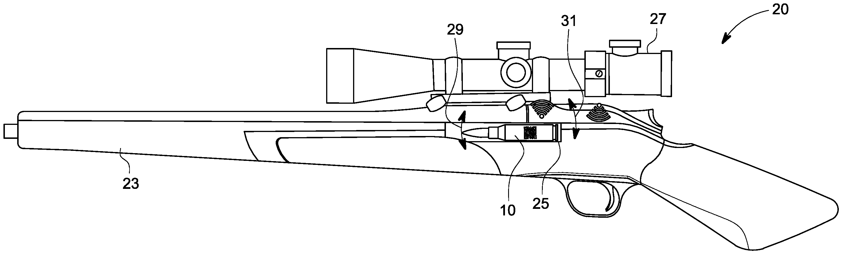
1 eine schematische Darstellung einer beispielhaften Ausführung einer erfindungsgemäßen Schusswaffe; -
2 eine perspektivische Ansicht einer beispielhaften Ausführung einer erfindungsgemäßen Munition; -
3 eine perspektivische schematische Ansicht der Munition aus2 in einem schematisch angedeuteten Schusswaffenlauf; -
4 eine Detailansicht gemäß demPfeil IV aus 3 ; -
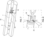
5 eine Teilschnittansicht eines Ausschnitts einer beispielhaften Ausführung einer erfindungsgemäßen Schusswaffe; -
6 eine Detailansicht zu 5 ; -
7 eine perspektivische Teilschnittansicht eines Ausschnitts einer beispielhaften Ausführung einer erfindungsgemäßen Schusswaffe; und -
8 eine Detailansicht zu 7 .
-
1 a schematic representation of an exemplary embodiment of a firearm according to the invention; -
2 a perspective view of an exemplary embodiment of an ammunition according to the invention; -
3 a perspective schematic view of the ammunition from2 in a schematically indicated firearm barrel; -
4 a detailed view according toarrow IV 3 ; -
5 a partial sectional view of a section of an exemplary embodiment of a firearm according to the invention; -
6 a detailed view of5 ; -
7 a perspective partial sectional view of a section of an exemplary embodiment of a firearm according to the invention; and -
8 a detailed view of7 .
In der folgenden Beschreibung beispielhafter Ausführungen der vorliegenden Erfindung ist ein erfindungsgemäßes Bodenstück im Allgemeinen mit der Bezugsziffer 1 versehen, eine erfindungsgemäße Munition mit dem Bezugszeichen 10 und eine erfindungsgemäße Schusswaffe mit dem Bezugszeichen 20.In the following description of exemplary embodiments of the present invention, a base piece according to the invention is generally provided with the
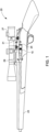
In
Die Schusswaffe 20 kann eine mit der Zielhilfe 27 signalübertragend verbundene Steuerung und einen Motor zum Justieren der Zielhilfe 27 aufweisen. Dabei kann die Steuerung dazu eingerichtet sein, in Abhängigkeit der von der Ausleseeinrichtung 30 ausgelesenen Daten die Zielhilfe 27 zu kalibrieren. Ferner kann die Schusswaffe einen Speicher umfassen, auf dem zu den munitionsspezifischen Daten korrespondierende schusswaffenspezifische, insbesondere zielhilfespezifische, Daten hinterlegt sein können oder eine Kommunikationsschnittstelle zum Abrufen von zu den munitionsspezifischen Daten korrespondierenden schusswaffenspezifischen, insbesondere zielhilfespezifischen, Daten aus einem externen Datenspeicher, wie einer Cloud. Die Steuerung kann dazu eingerichtet sein, in Abhängigkeit der von der Ausleseeinrichtung 30 ausgelesenen Daten und unter Berücksichtigung der schusswaffenspezifischen, insbesondere zielhilfespezifischen, Daten die Zielhilfe 27 zu kalibrieren.The
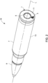
Die beispielhafte Ausführung einer erfindungsgemäßen Munition 10 gemäß
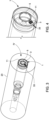
Aus den
Die
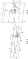
Die Ausführung der
Die in der vorstehenden Beschreibung, den Figuren und den Ansprüchen offenbarten Merkmale können sowohl einzeln als auch in beliebiger Kombination für die Realisierung der Erfindung in den verschiedenen Ausgestaltungen von Bedeutung sein.The features disclosed in the above description, the figures and the claims can be important both individually and in any combination for the realization of the invention in the various embodiments.
Bezugszeichenlistelist of reference symbols
- 11
- Bodenstückbottom piece
- 33
- Codecode
- 55
- Anzündhütchenpercussion cap
- 77
- Hülsenmantelsleeve shell
- 99
- Projektilprojectile
- 1010
- Munitionammunition
- 1111
- Stirnflächefrontal surface
- 1313
- UmfangScope
- 2020
- Schusswaffefirearm
- 2323
- Laufrun
- 2525
- Patronenlagercartridge chamber
- 2727
- Zielhilfeaim assist
- 29, 3129, 31
- PfeilArrow
- 3030
- Ausleseeinrichtungreading device
- 3333
- Markermarker
- 3535
- Zugang Access
- LL
- Längsachselongitudinal axis
Claims (7)
Priority Applications (1)
| Application Number | Priority Date | Filing Date | Title |
|---|---|---|---|
| DE102023108793.2A DE102023108793B4 (en) | 2023-04-05 | 2023-04-05 | Base, ammunition, firearm and firearm system and method for calibrating a firearm |
Applications Claiming Priority (1)
| Application Number | Priority Date | Filing Date | Title |
|---|---|---|---|
| DE102023108793.2A DE102023108793B4 (en) | 2023-04-05 | 2023-04-05 | Base, ammunition, firearm and firearm system and method for calibrating a firearm |
Publications (2)
| Publication Number | Publication Date |
|---|---|
| DE102023108793A1 DE102023108793A1 (en) | 2024-10-10 |
| DE102023108793B4 true DE102023108793B4 (en) | 2024-10-17 |
Family
ID=92801982
Family Applications (1)
| Application Number | Title | Priority Date | Filing Date |
|---|---|---|---|
| DE102023108793.2A Expired - Fee Related DE102023108793B4 (en) | 2023-04-05 | 2023-04-05 | Base, ammunition, firearm and firearm system and method for calibrating a firearm |
Country Status (1)
| Country | Link |
|---|---|
| DE (1) | DE102023108793B4 (en) |
Citations (17)
| Publication number | Priority date | Publication date | Assignee | Title |
|---|---|---|---|---|
| DE2260693A1 (en) * | 1971-12-17 | 1973-06-28 | Hughes Aircraft Co | FIRE CONTROL SYSTEM FOR ANTI-AIRCRAFT |
| DE4137819A1 (en) | 1991-11-16 | 1993-05-19 | Wegmann & Co Gmbh | Data carrier e.g. ROM or RAM memory for identifying munitions - contains manually and=or automatically written and read data carriers at defined positions on munitions |
| DE3830903C2 (en) | 1988-09-10 | 1995-03-23 | Mauser Werke Oberndorf | Process for the detection of different types of ammunition and ammunition for carrying out the process |
| WO2005024337A2 (en) * | 2003-07-09 | 2005-03-17 | Ravensforge Llc | Apparatus and method for identifying ammunition |
| DE102005040407A1 (en) * | 2005-08-26 | 2007-03-15 | Rheinmetall Waffe Munition Gmbh | Apparatus for identifying the ammunition type of ammunition |
| DE102006036257A1 (en) | 2006-08-03 | 2008-02-07 | Rheinmetall Defence Electronics Gmbh | Ballistic weapon conduit`s discontinued alignment determining method, involves measuring trajectories of projectile from preset parameter e.g. initial speed of projectile, and variable parameters of rate action and/or composition of conduit |
| US20100251593A1 (en) * | 2004-10-13 | 2010-10-07 | Dr. Gert Johansson | Device for Automatic Calibration of Scopes for Firearms |
| DE102010016963A1 (en) | 2010-05-17 | 2011-11-17 | Krauss-Maffei Wegmann Gmbh & Co. Kg | Weapon system, method for firing and detecting ammunition bodies |
| US20120126001A1 (en) | 2010-11-22 | 2012-05-24 | Irvine Sensors Corporation | Self-Calibrating Targeting Sight |
| EP3367047A1 (en) | 2011-04-06 | 2018-08-29 | Swarovski-Optik KG. | Target device |
| DE102017004413A1 (en) | 2017-05-09 | 2018-11-15 | Daniel Dentler | Multi-weapon system with a rifle scope |
| DE102019102722A1 (en) | 2019-02-04 | 2020-08-06 | Ruag Ammotec Gmbh | Bullet with a caliber of less than 13 mm and bullet tracking system |
| US20200355450A1 (en) | 2018-03-08 | 2020-11-12 | Maztech Industries, LLC | Firearm ammunition availability detection system |
| US20200371128A1 (en) * | 2019-05-23 | 2020-11-26 | Peter Todd Williams | System for determining muzzle velocity of a firearm |
| US20210148687A1 (en) * | 2019-11-20 | 2021-05-20 | US Strategic LLC | Method of Manufacturing A Cartridge Case |
| WO2021194578A2 (en) * | 2019-12-11 | 2021-09-30 | Tello Selso | Firearm sighting system with remote sensors |
| DE102020127053A1 (en) * | 2020-10-14 | 2022-04-14 | Ruag Ammotec Ag | Cartridge case for centerfire ammunition and centerfire ammunition |
-
2023
- 2023-04-05 DE DE102023108793.2A patent/DE102023108793B4/en not_active Expired - Fee Related
Patent Citations (17)
| Publication number | Priority date | Publication date | Assignee | Title |
|---|---|---|---|---|
| DE2260693A1 (en) * | 1971-12-17 | 1973-06-28 | Hughes Aircraft Co | FIRE CONTROL SYSTEM FOR ANTI-AIRCRAFT |
| DE3830903C2 (en) | 1988-09-10 | 1995-03-23 | Mauser Werke Oberndorf | Process for the detection of different types of ammunition and ammunition for carrying out the process |
| DE4137819A1 (en) | 1991-11-16 | 1993-05-19 | Wegmann & Co Gmbh | Data carrier e.g. ROM or RAM memory for identifying munitions - contains manually and=or automatically written and read data carriers at defined positions on munitions |
| WO2005024337A2 (en) * | 2003-07-09 | 2005-03-17 | Ravensforge Llc | Apparatus and method for identifying ammunition |
| US20100251593A1 (en) * | 2004-10-13 | 2010-10-07 | Dr. Gert Johansson | Device for Automatic Calibration of Scopes for Firearms |
| DE102005040407A1 (en) * | 2005-08-26 | 2007-03-15 | Rheinmetall Waffe Munition Gmbh | Apparatus for identifying the ammunition type of ammunition |
| DE102006036257A1 (en) | 2006-08-03 | 2008-02-07 | Rheinmetall Defence Electronics Gmbh | Ballistic weapon conduit`s discontinued alignment determining method, involves measuring trajectories of projectile from preset parameter e.g. initial speed of projectile, and variable parameters of rate action and/or composition of conduit |
| DE102010016963A1 (en) | 2010-05-17 | 2011-11-17 | Krauss-Maffei Wegmann Gmbh & Co. Kg | Weapon system, method for firing and detecting ammunition bodies |
| US20120126001A1 (en) | 2010-11-22 | 2012-05-24 | Irvine Sensors Corporation | Self-Calibrating Targeting Sight |
| EP3367047A1 (en) | 2011-04-06 | 2018-08-29 | Swarovski-Optik KG. | Target device |
| DE102017004413A1 (en) | 2017-05-09 | 2018-11-15 | Daniel Dentler | Multi-weapon system with a rifle scope |
| US20200355450A1 (en) | 2018-03-08 | 2020-11-12 | Maztech Industries, LLC | Firearm ammunition availability detection system |
| DE102019102722A1 (en) | 2019-02-04 | 2020-08-06 | Ruag Ammotec Gmbh | Bullet with a caliber of less than 13 mm and bullet tracking system |
| US20200371128A1 (en) * | 2019-05-23 | 2020-11-26 | Peter Todd Williams | System for determining muzzle velocity of a firearm |
| US20210148687A1 (en) * | 2019-11-20 | 2021-05-20 | US Strategic LLC | Method of Manufacturing A Cartridge Case |
| WO2021194578A2 (en) * | 2019-12-11 | 2021-09-30 | Tello Selso | Firearm sighting system with remote sensors |
| DE102020127053A1 (en) * | 2020-10-14 | 2022-04-14 | Ruag Ammotec Ag | Cartridge case for centerfire ammunition and centerfire ammunition |
Non-Patent Citations (1)
| Title |
|---|
| Rheinmetall Industrie GmbH Ratingen: Waffentechnisches Taschenbuch. 9. Auflage. Frankfurt am Main : Brönners Druckerei Breidenstein GmbH, 1995. Seite 224. 6.3.2 Feuerleitgeräte für die Feld- und Panzerartillerie. - ISBN keine ISBN * |
Also Published As
| Publication number | Publication date |
|---|---|
| DE102023108793A1 (en) | 2024-10-10 |
Similar Documents
| Publication | Publication Date | Title |
|---|---|---|
| DE102005013117A1 (en) | Rifle with a aiming device | |
| DE69709083T2 (en) | METHOD AND DEVICE FOR PROGRAMMING A FLOOR | |
| DE19716227A1 (en) | Weapon system | |
| DE10257901A1 (en) | Safety device and method for firearms and cartridges | |
| DE102023108793B4 (en) | Base, ammunition, firearm and firearm system and method for calibrating a firearm | |
| EP2146175B1 (en) | Submunition and method for destroying a target in a target zone using the submunition | |
| EP1757894B1 (en) | Device for identifying the ammunition type | |
| DE102007049438B4 (en) | Method for the defense of ballistic missiles with the help of guided missiles | |
| EP0715146A1 (en) | Device to locate artillery or sniper positions | |
| EP2572153B1 (en) | Weapon system and method for firing and detecting ammunition bodies | |
| DE102009058566A1 (en) | Propellant charge and device and method for determining a Feuerleitlösung | |
| DE102009058565A1 (en) | Device and method for identifying projectiles and / or propellant charges for a particularly heavy weapon | |
| EP3921592B1 (en) | Projectile having a caliber of less than 13 mm and system for tracking a projectile | |
| DE102016005911A1 (en) | Measuring projectile and method for measuring a condition of a gun by means of a measuring projectile | |
| DE102018129778B4 (en) | Practice ammunition and training system using practice ammunition | |
| US7296520B1 (en) | External telemetry unit | |
| EP0878685B1 (en) | Weapons system | |
| DE69817496T2 (en) | Hollow charge projectile and associated weapon system | |
| DE102013108822B4 (en) | Weapon and projectile with RFID system | |
| WO2001092814A2 (en) | Cartridge, launching device for launching cartridges and method for producing a cartridge | |
| DE102021101262B4 (en) | Small caliber tracking bullet | |
| DE102023133088B3 (en) | Noise filter for radar measuring systems, radar measuring system and launch device with radar measuring system | |
| DE10105157A1 (en) | Cartridge, cartridge firing device and cartridge manufacturing method | |
| DE19935816C2 (en) | Automatic system for the calibration of target devices (telescopes) on rifles using a laser beam and servomotors | |
| DE102010009625B3 (en) | Method for hit detection during practice shooting |
Legal Events
| Date | Code | Title | Description |
|---|---|---|---|
| R012 | Request for examination validly filed | ||
| R016 | Response to examination communication | ||
| R016 | Response to examination communication | ||
| R018 | Grant decision by examination section/examining division | ||
| R020 | Patent grant now final | ||
| R119 | Application deemed withdrawn, or ip right lapsed, due to non-payment of renewal fee |