DE102019102722A1 - Bullet with a caliber of less than 13 mm and bullet tracking system - Google Patents
Bullet with a caliber of less than 13 mm and bullet tracking system Download PDFInfo
- Publication number
- DE102019102722A1 DE102019102722A1 DE102019102722.5A DE102019102722A DE102019102722A1 DE 102019102722 A1 DE102019102722 A1 DE 102019102722A1 DE 102019102722 A DE102019102722 A DE 102019102722A DE 102019102722 A1 DE102019102722 A1 DE 102019102722A1
- Authority
- DE
- Germany
- Prior art keywords
- projectile
- position transmitter
- energy source
- transmitter
- cavity
- Prior art date
- Legal status (The legal status is an assumption and is not a legal conclusion. Google has not performed a legal analysis and makes no representation as to the accuracy of the status listed.)
- Ceased
Links
- 238000010304 firing Methods 0.000 claims description 12
- 239000000615 nonconductor Substances 0.000 claims description 11
- 239000012212 insulator Substances 0.000 claims description 6
- 230000001133 acceleration Effects 0.000 claims description 4
- 230000006378 damage Effects 0.000 claims description 4
- 230000005540 biological transmission Effects 0.000 description 10
- 239000006096 absorbing agent Substances 0.000 description 7
- 229910052751 metal Inorganic materials 0.000 description 7
- 239000002184 metal Substances 0.000 description 7
- 238000010521 absorption reaction Methods 0.000 description 4
- 241001465754 Metazoa Species 0.000 description 3
- RYGMFSIKBFXOCR-UHFFFAOYSA-N Copper Chemical compound [Cu] RYGMFSIKBFXOCR-UHFFFAOYSA-N 0.000 description 2
- 229910000831 Steel Inorganic materials 0.000 description 2
- 229910052802 copper Inorganic materials 0.000 description 2
- 239000010949 copper Substances 0.000 description 2
- 230000008878 coupling Effects 0.000 description 2
- 238000010168 coupling process Methods 0.000 description 2
- 238000005859 coupling reaction Methods 0.000 description 2
- 239000011133 lead Substances 0.000 description 2
- 239000000463 material Substances 0.000 description 2
- 238000005259 measurement Methods 0.000 description 2
- 238000000034 method Methods 0.000 description 2
- NDVLTYZPCACLMA-UHFFFAOYSA-N silver oxide Chemical compound [O-2].[Ag+].[Ag+] NDVLTYZPCACLMA-UHFFFAOYSA-N 0.000 description 2
- 239000011343 solid material Substances 0.000 description 2
- 239000010959 steel Substances 0.000 description 2
- 229910001369 Brass Inorganic materials 0.000 description 1
- WHXSMMKQMYFTQS-UHFFFAOYSA-N Lithium Chemical compound [Li] WHXSMMKQMYFTQS-UHFFFAOYSA-N 0.000 description 1
- 230000003213 activating effect Effects 0.000 description 1
- 239000010951 brass Substances 0.000 description 1
- 238000001514 detection method Methods 0.000 description 1
- 239000007772 electrode material Substances 0.000 description 1
- 230000005672 electromagnetic field Effects 0.000 description 1
- 229910052744 lithium Inorganic materials 0.000 description 1
- 229910000474 mercury oxide Inorganic materials 0.000 description 1
- UKWHYYKOEPRTIC-UHFFFAOYSA-N mercury(ii) oxide Chemical compound [Hg]=O UKWHYYKOEPRTIC-UHFFFAOYSA-N 0.000 description 1
- 229910001092 metal group alloy Inorganic materials 0.000 description 1
- 231100001160 nonlethal Toxicity 0.000 description 1
- 230000035699 permeability Effects 0.000 description 1
- 229910001923 silver oxide Inorganic materials 0.000 description 1
- 238000003466 welding Methods 0.000 description 1
Images
Classifications
-
- F—MECHANICAL ENGINEERING; LIGHTING; HEATING; WEAPONS; BLASTING
- F42—AMMUNITION; BLASTING
- F42B—EXPLOSIVE CHARGES, e.g. FOR BLASTING, FIREWORKS, AMMUNITION
- F42B12/00—Projectiles, missiles or mines characterised by the warhead, the intended effect, or the material
- F42B12/02—Projectiles, missiles or mines characterised by the warhead, the intended effect, or the material characterised by the warhead or the intended effect
- F42B12/36—Projectiles, missiles or mines characterised by the warhead, the intended effect, or the material characterised by the warhead or the intended effect for dispensing materials; for producing chemical or physical reaction; for signalling ; for transmitting information
- F42B12/365—Projectiles transmitting information to a remote location using optical or electronic means
-
- F—MECHANICAL ENGINEERING; LIGHTING; HEATING; WEAPONS; BLASTING
- F42—AMMUNITION; BLASTING
- F42B—EXPLOSIVE CHARGES, e.g. FOR BLASTING, FIREWORKS, AMMUNITION
- F42B12/00—Projectiles, missiles or mines characterised by the warhead, the intended effect, or the material
- F42B12/02—Projectiles, missiles or mines characterised by the warhead, the intended effect, or the material characterised by the warhead or the intended effect
- F42B12/36—Projectiles, missiles or mines characterised by the warhead, the intended effect, or the material characterised by the warhead or the intended effect for dispensing materials; for producing chemical or physical reaction; for signalling ; for transmitting information
- F42B12/40—Projectiles, missiles or mines characterised by the warhead, the intended effect, or the material characterised by the warhead or the intended effect for dispensing materials; for producing chemical or physical reaction; for signalling ; for transmitting information of target-marking, i.e. impact-indicating type
-
- F—MECHANICAL ENGINEERING; LIGHTING; HEATING; WEAPONS; BLASTING
- F42—AMMUNITION; BLASTING
- F42B—EXPLOSIVE CHARGES, e.g. FOR BLASTING, FIREWORKS, AMMUNITION
- F42B30/00—Projectiles or missiles, not otherwise provided for, characterised by the ammunition class or type, e.g. by the launching apparatus or weapon used
- F42B30/02—Bullets
Landscapes
- Engineering & Computer Science (AREA)
- General Engineering & Computer Science (AREA)
- Chemical & Material Sciences (AREA)
- Combustion & Propulsion (AREA)
- Aiming, Guidance, Guns With A Light Source, Armor, Camouflage, And Targets (AREA)
Abstract
Die vorliegende Erfindung betrifft ein Geschoss mit einem Kaliber von weniger als 13 mm, umfassend einen einen Hohlraum begrenzenden Geschossmantel und einen in dem Hohlraum angeordneten Positionssender.The present invention relates to a projectile with a caliber of less than 13 mm, comprising a projectile jacket delimiting a cavity and a position transmitter arranged in the cavity.
Description
Die vorliegende Erfindung betrifft ein Geschoss mit einem Kaliber von weniger als 13 mm. Ferner betrifft die vorliegende Erfindung ein System zum Nachverfolgen eines derartigen Geschosses.The present invention relates to a projectile with a caliber of less than 13 mm. The present invention further relates to a system for tracking such a projectile.
Beim jagdlichen Einsatz von Schusswaffen ist es notwendig, das angeschossene Tier aufzufinden. Dies kann durch verschiedene Umstände erschwert werden. Beispielsweise kann es vorkommen, dass kein ausgebildeter Schweißhund zur Verfügung steht oder ein non-letaler Anschuss zum Beispiel in der Dämmerung angetragen wird, sodass ein nachträgliches Suchen des verletzten Tieres unmöglich ist. Im jagdlichen Einsatz besteht daher ein allgemeiner Bedarf, das Auffinden von angeschossenen Tieren, ob tot oder lebendig, zu erleichtern.When using firearms for hunting, it is necessary to find the shot animal. Various circumstances can make this difficult. For example, it may happen that a trained welding dog is not available or a non-lethal connection is made, for example at dusk, so that it is impossible to find the injured animal afterwards. In hunting, there is therefore a general need to make it easier to find shot animals, whether dead or alive.
Im militärisch-behördlichen Einsatz kann es erforderlich sein, ein Ziel zu markieren, um dessen Position verfolgen und/oder Bewegungsprofile generieren zu können.In military and official use, it may be necessary to mark a target in order to be able to track its position and / or generate movement profiles.
Bei Großkaliber-Anwendungen ist digital-verfolgungsfähige Munition bekannt, allerdings mit dem Ziel, das Großkaliber-Geschoss nach dem Abschuss zu lenken und/oder zu steuern. Beim Auftreffen des Geschosses auf ein Ziel zündet das Großkaliber-Geschoss, sodass es samt dessen Elektronik zerstört wird. Die große Dimension der Großkaliber-Munition ermöglicht es, die für die digitale Nachverfolgung des Geschosses erforderliche Elektronik, wie einen Positionssender und eine Energiequelle, in dem Geschoss unterzubringen. Im Bereich der Kleinkaliber-Munition existiert eine in das Geschoss integrierte Elektronik bisher nicht. Des Weiteren existiert bislang keine Lösung, bei der die Elektronik nach dem Auftreffen des Geschosses auf ein Ziel intakt bleibt.In large-caliber applications, digitally traceable ammunition is known, but with the aim of directing and / or controlling the large-caliber projectile after it has been fired. When the bullet strikes a target, the large-caliber bullet fires, so that it and its electronics are destroyed. The large size of the large-caliber ammunition makes it possible to accommodate the electronics required for digital tracking of the projectile, such as a position transmitter and an energy source, in the projectile. In the area of small-caliber ammunition, electronics integrated into the projectile do not yet exist. Furthermore, so far there is no solution in which the electronics remain intact after the bullet hits a target.
Es ist Aufgabe der vorliegenden Erfindung, die Nachteile aus dem bekannten Stand der Technik zu verbessern, insbesondere ein Geschoss mit einem Kaliber von weniger als 13 mm und ein System zum Nachverfolgen eines derartigen Geschosses bereitzustellen, dessen Position nach dem Abfeuern der Schusswaffe nachverfolgbar ist.It is an object of the present invention to improve the disadvantages of the known prior art, in particular to provide a projectile with a caliber of less than 13 mm and a system for tracking such a projectile, the position of which can be tracked after the firing of the firearm.
Diese Aufgabe wird durch die Merkmale von Anspruch 1 bzw. 14 gelöst.This object is solved by the features of
Danach ist ein Geschoss mit einem Kaliber von weniger als 13 mm, vorzugsweise etwa 12,7 mm, weniger als 12 mm, 11 mm, 10 mm, 9 mm, 8 mm, 7 mm oder weniger als 6 mm, bereitgestellt. Das Kaliber ist im Allgemeinen ein Maß für den Außendurchmesser eines Geschosses und/oder den Innendurchmesser eines Laufes einer Schusswaffe.A bullet with a caliber of less than 13 mm, preferably about 12.7 mm, less than 12 mm, 11 mm, 10 mm, 9 mm, 8 mm, 7 mm or less than 6 mm, is then provided. The caliber is generally a measure of the outside diameter of a projectile and / or the inside diameter of a barrel of a firearm.
Das Geschoss umfasst einen Geschossmantel vorzugsweise aus Metall, Metall-Legierungen, Beispielsweise umfassend Stahl, Messing, Kupfer, Blei, oder dergleichen. Der Geschossmantel kann die äußere Form des Geschosses festlegen. Ferner kann der Geschossmantel sich entlang einer Geschosslängsachse erstrecken und/oder rotationssymmetrisch bezüglich einer Mittelachse des Geschosses aufgebaut sein. Der Geschossmantel begrenzt in seinem Inneren einen Hohlraum. Dies bedeutet, dass der Geschossmantel teilweise hohl ausgestaltet sein kann.The projectile comprises a projectile jacket preferably made of metal, metal alloys, for example comprising steel, brass, copper, lead, or the like. The projectile jacket can determine the external shape of the projectile. Furthermore, the projectile jacket can extend along a longitudinal axis of the projectile and / or be constructed rotationally symmetrically with respect to a central axis of the projectile. The bullet jacket delimits a cavity in its interior. This means that the shell of the projectile can be partially hollow.
Erfindungsgemäß ist in dem Hohlraum ein Positionssender angeordnet. Damit ist die Position des Geschosses nach dessen Abschluss nachverfolgbar. Der Positionssender kann dazu ausgebildet sein, Positionssignale auszusenden, die beispielsweise von einem Positionssignalempfänger erfasst werden können.According to the invention, a position transmitter is arranged in the cavity. This means that the position of the projectile can be tracked after it has been completed. The position transmitter can be designed to transmit position signals that can be detected, for example, by a position signal receiver.
Gemäß einer Weiterbildung der vorliegenden Erfindung können Telemetriesender eingesetzt werden. Als Telemetrie oder Fernmessung kann im Allgemeinen die Übertragung von Signalen eines an einem beliebigen Ort sich befindenden Signalgebers zu einem räumlich getrennten Ort, insbesondere an dem die übertragenen Signale gesammelt, aufgezeichnet und/oder ausgewertet werden können. Beispielsweise kann der Positionssender ein RFID-Transponder („radio-frequency identification“) sein. RFID-Transponder unterscheiden sich beispielsweise nach der Übertragungsfrequenz, wobei gemäß der vorliegenden Erfindung diesbezüglich keine Beschränkungen bestehen. Der Aufbau eines RFID-Transponders kann beispielsweise wie folgt aufgebaut sein: eine Antenne, wenigstens ein Schaltkreis zum Empfangen und Senden (Transceiver), wie ein Mikrocontroller, und ein Speicher, der die vorzugsweise unveränderliche Identität des Geschosses enthält. Des Weiteren ist es möglich, dass der Positionssender ein GPS-Sender ist („Global Positioning System“). Das globale Positionsbestimmungssystem ist ein globales Navigationssatellitensystem zur Positionsbestimmung, also ein System zur Positionsbestimmung auf der Erde und in der Luft durch den Empfang von Signalen von Navigationssatelliten und/oder Pseudoliten. Des Weiteren können GPS-basierte Lösungen angedacht sein, bei denen der Positionssender selbst keine Positionssignale aussendet, sondern als GPS-Empfänger realisiert ist, der Funkwellen des GPS-Systems beispielsweise von dem Satelliten oder Pseudoliten empfängt und damit die Positionsbestimmung und -verfolgung über eine Laufzeit- und Distanzbestimmung bzw. -messung in Bezug auf den Sender erfolgt. Es sei klar, dass jegliche weitere Art bzw. Typ Positionssender in den Offenbarungsgehalt der vorliegenden Anmeldung mit inbegriffen ist, der für den erfindungsgemäßen Zweck geeignet ist, insbesondere die Anforderungen an Sendereichweiten im Kilometerbereich bzw. global, Dimensionierung und Sendestärke, um in dem Geschossmantelhohlraum untergebracht zu werden und eine Positionserfassung ermöglicht.According to a development of the present invention, telemetry transmitters can be used. In general, telemetry or remote measurement can be used to transmit signals from a signal transmitter located at any location to a spatially separate location, in particular at which the transmitted signals can be collected, recorded and / or evaluated. For example, the position transmitter can be an RFID transponder ("radio frequency identification"). RFID transponders differ, for example, according to the transmission frequency, whereby there are no restrictions in this regard according to the present invention. The structure of an RFID transponder can be constructed as follows, for example: an antenna, at least one circuit for receiving and transmitting (transceiver), such as a microcontroller, and a memory which contains the preferably unchangeable identity of the projectile. It is also possible that the position transmitter is a GPS transmitter ("Global Positioning System"). The global positioning system is a global navigation satellite system for determining the position, that is to say a system for determining the position on earth and in the air by receiving signals from navigation satellites and / or pseudolites. Furthermore, GPS-based solutions can be envisaged, in which the position transmitter itself does not emit position signals, but is instead implemented as a GPS receiver that receives radio waves from the GPS system, for example from the satellite or pseudolite, and thus position determination and tracking over a period of time - and distance determination or measurement is carried out in relation to the transmitter. It should be clear that any other type or type of position transmitter is included in the disclosure content of the present application, which is suitable for the purpose according to the invention, in particular the requirements for transmission ranges in the Mileage range or global, dimensioning and transmission strength in order to be accommodated in the projectile jacket cavity and to enable position detection.
Zur Erhöhung der Sende- und/oder Empfangsleistung des Positionssenders kann es vorgesehen sein, dass der Geschossmantel wenigstens abschnittsweise entlang einer Geschosslängsrichtung einen Transmissionsabschnitt, vorzugsweise aus Kunststoff, besitzt, der sich durch eine erhöhte Durchlässigkeit für Signale, insbesondere elektromagnetische Wellen, im Vergleich zu dem restlichen Geschossmantel kennzeichnet. Der Positionssender kann beispielsweise dem Transmissionsabschnitt derart zugeordnet und/oder derart benachbart dem Transmissionsabschnitt in dem Hohlraum angeordnet sein, dass die von dem Positionssender ausgesendeten Positionssignale über den Transmissionsabschnitt nach außen gelangen. Gemäß einer beispielhaften Weiterbildung dient der Geschossmantel als Einrichtung zum Abstrahlen und/oder Empfangen von elektromagnetischen Wellen, insbesondere als Sende- und/oder Empfangs-Antenne. Dabei kann vorgesehen sein, dass ein Kontakt, beispielsweise mittels eines Kabels, zwischen Positionssender und Geschossmantel hergestellt ist. Der Positionssender kann beispielsweise einen Ausgangskontakt aufweisen, der mit einem Eingangskontakt des Geschossmantels gekoppelt ist, insbesondere derart, dass die von dem Positionssender erzeugten Positionssignale nach außen insbesondere in Form von Freiraumwellen mittels des Geschossmantels abgestrahlt werden. Gemäß einer Weiterbildung werden die Positionssignale im Wesentlichen ausschließlich über die Kopplung zwischen Positionssender und Geschossmantel ausgesendet und/oder empfangen. Dabei kann vorgesehen sein, dass der Positionssender bis auf die Kopplung mit dem Geschossmantel gegen eine Aussendung von Positionssignalen, wie elektromagnetischen Wellen, isoliert/abgeschirmt ist.To increase the transmission and / or reception power of the position transmitter, it can be provided that the projectile jacket has, at least in sections along a longitudinal direction of the projectile, a transmission section, preferably made of plastic, which is characterized by an increased permeability to signals, in particular electromagnetic waves, compared to that marks the remaining shell. The position transmitter can, for example, be assigned to the transmission section and / or be arranged adjacent to the transmission section in the cavity such that the position signals emitted by the position transmitter reach the outside via the transmission section. According to an exemplary development, the projectile jacket serves as a device for emitting and / or receiving electromagnetic waves, in particular as a transmitting and / or receiving antenna. It can be provided that a contact is established, for example by means of a cable, between the position transmitter and the projectile jacket. The position transmitter can, for example, have an output contact which is coupled to an input contact of the projectile jacket, in particular in such a way that the position signals generated by the position transmitter are emitted to the outside, in particular in the form of free space waves, by means of the projectile jacket. According to a further development, the position signals are transmitted and / or received essentially exclusively via the coupling between the position transmitter and the shell. It can be provided that the position transmitter is isolated / shielded from the transmission of position signals, such as electromagnetic waves, except for the coupling with the projectile jacket.
In einer beispielhaften Ausführung der vorliegenden Erfindung besitzt der Positionssender einen Passivzustand, in dem der Positionssender keine Positionssignale aussendet. Beispielsweise handelt es sich bei dem Passivzustand um einen energielosen Zustand, bei dem der Positionssender keine Energie empfängt, insbesondere nicht bestromt ist. Ferner kann der Positionssender einen Aktivzustand aufweisen, in dem der Positionssender Positionssignale aussendet. Der Aktivzustand kann beispielsweise dadurch gekennzeichnet sein, dass der Positionssender bestromt, insbesondere mit Energie versorgt, ist. Gemäß einer alternativen Ausgestaltung kann der Positionssender sowohl in dem Passivzustand als auch in dem Aktivzustand mit Energie versorgt, d. h. bestromt, sein, wobei ein Schalter zum Wechseln zwischen Aktiv- und Passivzustand vorgesehen sein kann. Dabei kann das Schalten von dem Passivzustand in den Aktivzustand als Aktivieren des Positionssenders und das Schalten von dem Aktivzustand in den Passivzustand als Deaktivieren des Positionssenders bezeichnet werden.In an exemplary embodiment of the present invention, the position transmitter has a passive state in which the position transmitter does not transmit any position signals. For example, the passive state is an energy-free state in which the position transmitter receives no energy, in particular is not energized. Furthermore, the position transmitter can have an active state in which the position transmitter transmits position signals. The active state can, for example, be characterized in that the position transmitter is energized, in particular supplied with energy. According to an alternative embodiment, the position transmitter can be supplied with energy both in the passive state and in the active state, i. H. be energized, a switch for switching between active and passive states can be provided. Switching from the passive state to the active state can be referred to as activating the position transmitter and switching from the active state to the passive state can be described as deactivating the position transmitter.
In einer weiteren beispielhaften Ausführung des erfindungsgemäßen Geschosses schaltet der Positionssender unmittelbar vor oder unmittelbar nach dem Abfeuern der Schusswaffe von dem Passivzustand in den Aktivzustand schaltet. Die Erfinder der vorliegenden Erfindung haben herausgefunden, dass eine Positionsverfolgung erst notwendig sein kann, wenn das Geschoss die Schusswaffe verlassen hat, also nach dem Abfeuern der Schusswaffe. Gemäß einer Weiterbildung kann vorgesehen sein, dass unmittelbar vor oder unmittelbar nach dem Abfeuern der Schusswaffe der Positionssender mit elektrischer Energie versorgt ist.In a further exemplary embodiment of the projectile according to the invention, the position transmitter switches from the passive state to the active state immediately before or immediately after the firing of the firearm. The inventors of the present invention have found that position tracking may only be necessary when the projectile has left the firearm, ie after the firing of the firearm. According to a further development, it can be provided that the position transmitter is supplied with electrical energy immediately before or immediately after the firing of the firearm.
Gemäß einer beispielhaften Weiterbildung der vorliegenden Erfindung ist in dem Hohlraum eine Energiequelle zum Versorgen des Positionssenders mit Energie, insbesondere zur Stromversorgung des Positionssenders, angeordnet. Die Energiequelle kann beispielsweise eine elektrische Batterie, insbesondere eine Knopfzelle, sein. Eine Knopfzelle ist im Allgemeinen eine elektrochemische Zelle beispielsweise mit rundem Querschnitt, dessen Höhe kleiner als der Durchmesser ist, und die Spannungen vorzugsweise zwischen 1,35 und 3,6 Volt abgibt. Die kleine Dimensionierung und ausreichende Spannungsabgabe von Knopfzellen ermöglichen deren Einsatz im Hohlraum eines Geschossmantels eines erfindungsgemäßen Geschosses. Je nach Elektrodenmaterial, Silberoxid, Quecksilberoxid oder Lithium, lassen sich Knopfzellen unterscheiden. In einer weiteren beispielhaften Ausführung ist die Energiequelle in dem Passivzustand frei von einem elektrischen Kontakt mit dem Positionssender und steht in dem Aktivzustand in elektrischem Kontakt mit dem Positionssender.According to an exemplary development of the present invention, an energy source for supplying the position transmitter with energy, in particular for supplying power to the position transmitter, is arranged in the cavity. The energy source can be, for example, an electric battery, in particular a button cell. A button cell is generally an electrochemical cell, for example with a round cross section, the height of which is smaller than the diameter, and the voltages are preferably between 1.35 and 3.6 volts. The small dimensions and sufficient voltage output of button cells enable them to be used in the cavity of a shell of a projectile according to the invention. Depending on the electrode material, silver oxide, mercury oxide or lithium, button cells can be differentiated. In a further exemplary embodiment, the energy source is free from electrical contact with the position transmitter in the passive state and is in electrical contact with the position transmitter in the active state.
In einer beispielhaften Ausführung der vorliegenden Erfindung ist der Positionssender, insbesondere der RFID-Transponder, durch eine externe Energiequelle mit Strom versorgt. Beispielsweise kann vorgesehen sein, dass Positionssender durch die externe Energiequelle mit hochfrequenten Funkwellen von außen bestrombar ist. Dies kann dadurch realisiert sein, dass der RFID-Transponder einem hochfrequenten elektromagnetischen Wechselfeld ausgesetzt ist, welches Hochfrequenzenergie enthält, die zur Stromversorgung des RFID-Transponders genutzt wird.In an exemplary embodiment of the present invention, the position transmitter, in particular the RFID transponder, is supplied with power by an external energy source. For example, it can be provided that position transmitter can be energized from the outside with high-frequency radio waves by the external energy source. This can be achieved by exposing the RFID transponder to a high-frequency alternating electromagnetic field, which contains high-frequency energy that is used to power the RFID transponder.
In einer weiteren beispielhaften Ausführung des erfindungsgemäßen Geschosses ist/sind der Positionssender und gegebenenfalls die Energiequelle derart in dem Geschossmantelhohlraum angeordnet, dass der Positionssender und gegebenenfalls die Energiequelle nach dem Aufprall des Geschosses auf ein Ziel intakt bleibt/bleiben. Das Verhalten des Geschosses beim bzw. nach dem Auftreffen des Geschosses auf das Ziel kann als Endballistik oder Zielballistik bezeichnet werden. Erfindungsgemäß weist das Geschoss eine geeignete Endballistik auf, die es erlaubt, dass der Positionssender auch nach dem Auftreffen des Geschosses auf das Ziel weiterhin Positionssignale zum Ermöglichen des Nachverfolgen des Geschosses aussenden kann. Die Erfinder der vorliegenden Erfindung haben herausgefunden, dass dies durch geeignetes Anordnen von Positionssender und gegebenenfalls Energiequelle in dem Hohlraum und/oder Dimensionieren des Geschossmantels erreicht werden kann. Beispielsweise lässt sich die Kenntnis über das Deformationsverhalten des Geschosses, insbesondere des Geschossmantels, dazu nutzen, den Geschossmantel entsprechend zu dimensionieren und/oder den Positionssender und gegebenenfalls die Energiequelle entsprechend in dem Hohlraum anzuordnen. Beispielsweise wird der Geschossmantel derart dimensioniert, dass die beim Aufprall des Geschosses auf das Ziel entstehende Aufprall- und Deformationsenergie gezielt in Bereichen abgebaut wird, in denen der Positionssender und gegebenenfalls die Energiequelle sich nicht befinden.In a further exemplary embodiment of the projectile according to the invention, the position transmitter and, if appropriate, the energy source are / are arranged in the projectile shell cavity in such a way that the position transmitter and, if appropriate, the Energy source remains intact after the projectile hits a target. The behavior of the projectile when or after the projectile hits the target can be termed end ballistics or target ballistics. According to the invention, the projectile has suitable end ballistics, which allows the position transmitter to continue to send position signals to enable the projectile to be tracked even after the projectile hits the target. The inventors of the present invention have found that this can be achieved by suitably arranging the position transmitter and optionally the energy source in the cavity and / or dimensioning the projectile jacket. For example, knowledge of the deformation behavior of the projectile, in particular the projectile jacket, can be used to dimension the projectile jacket accordingly and / or to arrange the position transmitter and, if appropriate, the energy source accordingly in the cavity. For example, the projectile jacket is dimensioned in such a way that the impact and deformation energy generated when the projectile hits the target is deliberately reduced in areas in which the position transmitter and possibly the energy source are not located.
In einer beispielhaften Ausführung weist der Geschossmantel einen bugseitigen Ogivenabschnitt und einen dem Ogivenabschnitt gegenüberliegenden Heckabschnitt aufweist. Es kann vorgesehen sein, der Positionssender heckseitig in dem Hohlraum und die Energiequelle bugseitig in dem Hohlraum untergebracht ist.In an exemplary embodiment, the projectile jacket has a bow section on the bow side and a rear section opposite the bow section. It can be provided that the position transmitter is accommodated in the cavity on the rear side and the energy source is accommodated in the cavity on the bow side.
Gemäß einer beispielhaften Weiterbildung der vorliegenden Erfindung ist ein bugseitiger Ogivenabschnitt des Geschossmantels dazu eingerichtet, die beim Aufprall des Geschosses auf das Ziel resultierende Aufprall- und Deformationsenergie insbesondere größtenteils, vorzugsweise zu wenigstens 50 %, 60 %, 70 % oder zu wenigstens 80 %, aufzunehmen, insbesondere zu absorbieren. Beispielsweise umfasst der Ogivenabschnitt einen vorzugsweise separat von dem Geschossmantel hergestellten Absorber zum Absorbieren der Aufprall- und Deformationsenergie. Es kann ferner vorgesehen sein, dass die Aufprall- und Deformationsenergie derart in einen dem Ogivenabschnitt gegenüberliegenden Heckabschnitt übertragen wird, dass ein den Ogivenabschnitt mit dem Heckabschnitt verbindender Grundkörper des Geschossmantels im Wesentlichen unversehrt bleibt. Beispielsweise ist dass der Ogivenabschnitt, der Heckabschnitt und der Grundkörper aus einem Stück, vorzugsweise aus Metall, hergestellt. Durch das gezielte Übertragen der Aufprall- und Deformationsenergie zwischen Ogivenabschnitt und Heckabschnitt kann unter anderem gewährleistet werden, dass die in dem Hohlraum angeordnete Elektronik, also der Positionssender und gegebenenfalls die Energiequelle, intakt bleiben, sodass der Positionssender auch nach dem Aufprall des Geschosses auf das Ziel Positionssignale zum Nachverfolgen aussenden kann. Der Absorber kann beispielweise als Schichtaufbau bzw. als Sandwich-Struktur realisiert sein und/oder aus einer Abfolge von wenigstens zwei Schichten, vorzugsweise aus Metall, unterschiedlicher Dichte und/oder unterschiedlichem Ausdehnungskoeffizient bestehen. Dadurch kann die Aufprall- und Deformationsenergie vorteilhaft aufgenommen, insbesondere absorbiert und/oder abgebaut, werden.According to an exemplary development of the present invention, a bow-shaped ogive section of the projectile jacket is set up to absorb the impact and deformation energy resulting when the projectile hits the target, in particular for the most part, preferably at least 50%, 60%, 70% or at least 80% , especially to absorb. For example, the ogive section comprises an absorber, preferably manufactured separately from the projectile jacket, for absorbing the impact and deformation energy. It can further be provided that the impact and deformation energy is transmitted to a rear section opposite the ogive section such that a base body of the projectile jacket connecting the ogive section to the rear section remains essentially intact. For example, the ogive section, the rear section and the base body are made from one piece, preferably from metal. Through the targeted transmission of the impact and deformation energy between the ogive section and the rear section, it can be ensured, among other things, that the electronics arranged in the cavity, i.e. the position transmitter and possibly the energy source, remain intact, so that the position transmitter even after the projectile has impacted the target Can send position signals for tracking. The absorber can be implemented, for example, as a layer structure or as a sandwich structure and / or consist of a sequence of at least two layers, preferably of metal, of different density and / or of different expansion coefficient. As a result, the impact and deformation energy can advantageously be absorbed, in particular absorbed and / or broken down.
In einer weiteren beispielhaften Weiterbildung ist ein elektrischer Isolator zwischen dem Positionssender und der Energiequelle zum temporären Verhindern eines elektrischen Kontakts angeordnet. Insbesondere verhindert der elektrische Isolator einen elektrischen Kontakt in dem Passivzustand des Positionssenders, insbesondere gewährleistet der elektrische Isolator den Passivzustand. Beispielsweise ist der elektrische Isolator derart angeordnet, dass beim Entfernen des Isolators der Positionssender aktiviert wird. Dadurch kann sichergestellt werden, dass erst zu einem bestimmten Zeitpunkt der Positionssender in den Aktivzustand schaltet/aktiviert wird. Beispielsweise soll der Isolator unmittelbar vor oder unmittelbar nach dem Abfeuern der Schusswaffe entfernt werden. Ferner kann vorgesehen sein, dass beim Abfeuern der Schusswaffe entstehende Hitze ein Auflösen, vorzugsweise Schmelzen, des elektrischen Isolators bewirkt, vorzugsweise um den elektrischen Kontakt zwischen Energiequelle und Positionssender herzustellen und/oder den Positionssender zu aktivieren.In a further exemplary development, an electrical insulator is arranged between the position transmitter and the energy source for temporarily preventing electrical contact. In particular, the electrical insulator prevents electrical contact in the passive state of the position transmitter, in particular the electrical insulator ensures the passive state. For example, the electrical insulator is arranged such that the position transmitter is activated when the insulator is removed. This can ensure that the position transmitter is only switched / activated at a certain point in time. For example, the insulator should be removed immediately before or immediately after firing the firearm. It can further be provided that the heat generated when the firearm is fired causes the electrical insulator to dissolve, preferably melt, preferably in order to establish electrical contact between the energy source and the position transmitter and / or to activate the position transmitter.
Gemäß einer beispielhaften Weiterbildung sind der Positionssender und die Energiequelle derart in einem Abstand zueinander angeordnet, dass beim Aufprall des Geschosses auf ein Ziel die Aufprall- und Deformationsenergie eine bugseitige Deformation des Geschossmantels, insbesondere des Ogivenabschnitts, bewirkt, aufgrund dessen der elektrische Kontakt zwischen Positionssender und Energiequelle hergestellt wird. Gemäß dieser beispielhaften Ausführung wird der Positionssender beim Aufprall des Geschosses auf ein Ziel aktiviert, sodass eine Positionsbestimmung des Geschosses ab dem Zeitpunkt des Aufpralls ermöglicht ist.According to an exemplary development, the position transmitter and the energy source are arranged at a distance from one another in such a way that when the projectile impacts a target, the impact and deformation energy causes a bow-side deformation of the projectile shell, in particular the ogive section, on the basis of which the electrical contact between the position transmitter and Energy source is produced. According to this exemplary embodiment, the position transmitter is activated when the projectile hits the target, so that the position of the projectile can be determined from the time of the impact.
In einer weiteren beispielhaften Ausführung des erfindungsgemäßen Geschosses ist der Positionssender von der Energiequelle durch eine den Hohlraum in zwei Abteile unterteilende, insbesondere aus einem Stück mit dem Geschossmantel hergestellte, Abteilwand getrennt. Durch die Abteilwand kann der Passivzustand des Positionssenders sichergestellt werden, insbesondere der elektrische Kontakt zwischen Positionssender und Energiequelle verhindert werden. Beispielsweise ist die Abteilwand dazu eingerichtet, sich beim Aufprall des Geschosses auf ein Ziel derart zu deformieren, insbesondere zu zerstören, dass der elektrische Kontakt zwischen Positionssender und Energiequelle hergestellt ist. Ferner kann die Abteilwand derart dimensioniert sein, dass die beim Aufprall des Geschosses auf das Ziel resultierende, von einem bugseitigen Ogivenabschnitt über den Geschossmantel in die Abteilwand übertragene Aufprall- und Deformationsenergie das Deformieren, insbesondere Zerstören, der Abteilwand bewirkt.In a further exemplary embodiment of the projectile according to the invention, the position transmitter is separated from the energy source by a compartment wall dividing the cavity into two compartments, in particular made from one piece with the projectile jacket. The passive state of the position transmitter can be ensured by the compartment wall, in particular the electrical contact between the position transmitter and Energy source can be prevented. For example, the compartment wall is designed to deform, in particular to destroy, when the projectile hits a target, in particular to destroy it, so that the electrical contact between the position transmitter and the energy source is established. Furthermore, the compartment wall can be dimensioned in such a way that the impact and deformation energy resulting from a bow-shaped ogive section and transferred to the compartment wall in the compartment wall when the projectile hits the target causes the compartment wall to be deformed, in particular destroyed.
Gemäß einer beispielhaften Weiterbildung der vorliegenden Erfindung umfasst ein bugseitiger Ogivenabschnitt des Geschossmantels einen Applikator, vorzugsweise aus Metall, wie Blei, Stahl, Kupfer, oder dergleichen, der beim Auftreffen des Geschosses auf ein Ziel den Positionssender in Richtung der Energiequelle oder die Energiequelle in Richtung des Positionssenders zum Herstellen des elektrischen Kontakts drückt. Dabei kann vorgesehen sein, dass der Applikator aus einem unterschiedlichen Material, insbesondere unterschiedlicher Dichte und/oder unterschiedlichem Ausdehnungskoeffizienten, wie das Material des Geschossmantels besteht. Beispielweise kann der Applikator den Positionssender in Richtung der Energiequelle oder die Energiequelle in Richtung des Positionssenders unter Deformation, vorzugsweise Zerstörung, der Abteilwand drücken.According to an exemplary development of the present invention, a bow-shaped ogive section of the projectile jacket comprises an applicator, preferably made of metal, such as lead, steel, copper or the like, which, when the projectile strikes a target, the position transmitter in the direction of the energy source or the energy source in the direction of the Position transmitter presses to make the electrical contact. It can be provided that the applicator consists of a different material, in particular a different density and / or different expansion coefficient than the material of the projectile shell. For example, the applicator can press the position transmitter in the direction of the energy source or the energy source in the direction of the position transmitter with deformation, preferably destruction, of the compartment wall.
In einer weiteren beispielhaften Ausführung des erfindungsgemäßen Geschosses sind/ist der Positionssender und/oder die Energiequelle derart lose in dem Hohlraum angeordnet, dass beim Abfeuern der Schusswaffe auftretende und auf das Geschoss wirkende Beschleunigungskräfte den Positionssender dazu veranlassen, in einen elektrischen Kontakt mit der Energiequelle zu geraten. Mit lose angeordnet kann beispielweise gemeint sein, dass keine Befestigung, insbesondere Axialbefestigung in Geschosslängsrichtung, für die Energiequelle und/oder den Positionssender vorgesehen ist. Des Weiteren kann mit lose angeordnet gemeint sein, dass der Hohlraum des Geschossmantels mit einer eine Halteeinrichtung zum Halten der Energiequelle und/oder des Positionssenders derart eingearbeitet ist, dass vor dem Abfeuern der Schusswaffe die Energiequelle und/oder der Positionssender im Wesentlichen an dem Geschossmantel befestigt ist und nach dem Abfeuern der Schusswaffe sich die Energiequelle und/oder der Positionssender von der Halteeinrichtung lösen, um den elektrischen Kontakt herstellen zu können. Beispielweise kann die Halteeinrichtung aufgrund der auf das Geschoss wirkenden Beschleunigungskräfte überwunden, beispielsweise zerstört, werden. Ferner kann vorgesehen sein, dass beim Abfeuern der Schusswaffe auftretende und auf das Geschoss wirkende Beschleunigungskräfte den Positionssender und/oder die Energiequelle zu einer Bewegung in Richtung des jeweils anderen zum Herstellen des elektrischen Kontakts veranlassen.In a further exemplary embodiment of the projectile according to the invention, the position transmitter and / or the energy source are / are arranged so loosely in the cavity that acceleration forces which occur when the firearm is fired and act on the projectile cause the position transmitter to make electrical contact with the energy source devices. Loosely arranged can mean, for example, that no fastening, in particular axial fastening in the longitudinal direction of the floor, is provided for the energy source and / or the position transmitter. Furthermore, loosely arranged can mean that the cavity of the projectile jacket is incorporated with a holding device for holding the energy source and / or the position transmitter such that the energy source and / or the position transmitter is essentially attached to the projectile jacket before the firing of the firearm and after firing the firearm, the energy source and / or the position transmitter detach from the holding device in order to be able to make the electrical contact. For example, the holding device can be overcome, for example destroyed, due to the acceleration forces acting on the projectile. Furthermore, it can be provided that acceleration forces occurring during the firing of the firearm and acting on the projectile cause the position transmitter and / or the energy source to move in the direction of the other to produce the electrical contact.
Gemäß einem weiteren Aspekt der vorliegenden Erfindung, der mit den vorhergehenden Aspekten und beispielhaften Ausführungen kombinierbar ist, ist ein System zum Nachverfolgen eines Geschosses mit einem Kaliber von weniger als 13 mm bereitgestellt. Das erfindungsgemäße System umfasst ein Geschoss, das gemäß einem der zuvor beschriebenen Aspekte oder beispielhaften Ausführungen ausgestaltet ist, und einen Positionssignalempfänger zum Empfangen der von dem Positionssender des Geschosses ausgesendeten Positionssignale. Es kann vorgesehen sein, dass abhängig von dem verwendeten Positionssender ein entsprechender Positionssignalempfänger verwendet wird, der dazu eingerichtet ist, die von dem Positionssender ausgesendeten Positionssignale zu empfangen, zu verarbeiten und/oder auszuwerten. Des Weiteren kann der Positionssignalempfänger eine geeignete Software besitzen, die je nach Einsatzgebiet des erfindungsgemäßen Systems realisiert sein kann.According to a further aspect of the present invention, which can be combined with the preceding aspects and exemplary embodiments, a system for tracking a projectile with a caliber of less than 13 mm is provided. The system according to the invention comprises a projectile which is designed in accordance with one of the aspects described above or exemplary embodiments, and a position signal receiver for receiving the position signals transmitted by the position transmitter of the projectile. It can be provided that depending on the position transmitter used, a corresponding position signal receiver is used, which is set up to receive, process and / or evaluate the position signals transmitted by the position transmitter. Furthermore, the position signal receiver can have suitable software that can be implemented depending on the area of application of the system according to the invention.
Bevorzugte Ausführungen sind in den Unteransprüchen gegeben.Preferred statements are given in the subclaims.
Im Folgenden werden weitere Eigenschaften, Merkmale und Vorteile der Erfindung mittels Beschreibung bevorzugter Ausführungen der Erfindung anhand der beiliegenden beispielhaften Zeichnungen deutlich, in denen zeigen:
-
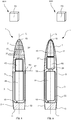
1 eine schematische Schnittansicht eines erfindungsgemäßen Geschosses; und -
2 eine schematische Schnittansicht einer weiteren Ausführung eines erfindungsgemäßen Geschosses.
-
1 is a schematic sectional view of a projectile according to the invention; and -
2nd is a schematic sectional view of a further embodiment of a projectile according to the invention.
In der folgenden Beschreibung beispielhafter Ausführungen ist ein erfindungsgemäßes Geschoss, das ein Kaliber von weniger als 13 mm, vorzugsweise von etwa 12,7 mm, aufweist, im Allgemeinen mit der Bezugsziffer
Bezugnehmend auf
Der Geschossmantel
Weiterhin bezugnehmend auf
Ferner umfasst der Ogivenabschnitt
Bezugnehmend auf
Weiterhin bezugnehmend auf
Der Positionssignalempfänger kann 23 abhängig von dem verwendeten Positionssender
Die in der vorstehenden Beschreibung, den Figuren und den Ansprüchen offenbarten Merkmale können sowohl einzeln als auch in beliebiger Kombination für die Realisierung der Erfindung in den verschiedenen Ausgestaltungen von Bedeutung sein.The features disclosed in the above description, the figures and the claims can be of importance both individually and in any combination for the implementation of the invention in the various configurations.
BezugszeichenlisteReference list
- 11
- Geschossbullet
- 33rd
- GeschossmantelBullet jacket
- 55
- OgivenabschnittOgiven section
- 77
- HeckabschnittRear section
- 99
- GrundkörperBasic body
- 1111
- HeckflächeRear surface
- 1313
- GeschossheckmantelflächeBullet rear surface
- 1515
- GeschossspitzeBullet tip
- 1717th
- GeschossbugmantelflächeBullet shell surface
- 1919th
- Hohlraumcavity
- 2121
- PositionssenderPosition transmitter
- 2323
- PositionssignalempfängerPosition signal receiver
- 2525th
- EnergiequelleEnergy source
- 2727
- Isolatorinsulator
- 2929
- Öffnungopening
- 31,3231.32
- Absorberabsorber
- 3333
- AbteilwandCompartment wall
- 35,3735.37
- Abteilcompartment
- 3939
- DurchgangsöffnungThrough opening
- 4141
- ApplikatorApplicator
- 100100
- System system
- LL
- GeschosslängsachseFloor longitudinal axis
Claims (14)
Priority Applications (4)
| Application Number | Priority Date | Filing Date | Title |
|---|---|---|---|
| DE102019102722.5A DE102019102722A1 (en) | 2019-02-04 | 2019-02-04 | Bullet with a caliber of less than 13 mm and bullet tracking system |
| EP20704230.0A EP3921592B1 (en) | 2019-02-04 | 2020-02-04 | Projectile having a caliber of less than 13 mm and system for tracking a projectile |
| US17/283,489 US11725917B2 (en) | 2019-02-04 | 2020-02-04 | Projectile having a caliber of less than 13 mm and a system for tracking a projectile |
| PCT/EP2020/052734 WO2020161123A1 (en) | 2019-02-04 | 2020-02-04 | Projectile having a caliber of less than 13 mm and system for tracking a projectile |
Applications Claiming Priority (1)
| Application Number | Priority Date | Filing Date | Title |
|---|---|---|---|
| DE102019102722.5A DE102019102722A1 (en) | 2019-02-04 | 2019-02-04 | Bullet with a caliber of less than 13 mm and bullet tracking system |
Publications (1)
| Publication Number | Publication Date |
|---|---|
| DE102019102722A1 true DE102019102722A1 (en) | 2020-08-06 |
Family
ID=69526227
Family Applications (1)
| Application Number | Title | Priority Date | Filing Date |
|---|---|---|---|
| DE102019102722.5A Ceased DE102019102722A1 (en) | 2019-02-04 | 2019-02-04 | Bullet with a caliber of less than 13 mm and bullet tracking system |
Country Status (4)
| Country | Link |
|---|---|
| US (1) | US11725917B2 (en) |
| EP (1) | EP3921592B1 (en) |
| DE (1) | DE102019102722A1 (en) |
| WO (1) | WO2020161123A1 (en) |
Cited By (2)
| Publication number | Priority date | Publication date | Assignee | Title |
|---|---|---|---|---|
| DE102021101262A1 (en) | 2021-01-21 | 2022-07-21 | Ruag Ammotec Gmbh | Small caliber tracking round |
| DE102023108793A1 (en) | 2023-04-05 | 2024-10-10 | Rws Gmbh | Base, ammunition, firearm and firearm system and method for calibrating a firearm |
Citations (6)
| Publication number | Priority date | Publication date | Assignee | Title |
|---|---|---|---|---|
| DE3518117A1 (en) * | 1985-05-21 | 1986-11-27 | Diehl GmbH & Co, 8500 Nürnberg | Item of ammunition having an electrical energy store |
| DE102012021449A1 (en) * | 2012-10-31 | 2014-04-30 | Bundesrepublik Deutschland, vertreten durch das BMVg, vertreten durch das Bundesamt für Ausrüstung, Informationstechnik und Nutzung der Bundeswehr | Fuze for detecting interruptible explosive train item, has detection device that is provided with detection unit that detects position of explosive train item |
| DE102012022894A1 (en) * | 2012-11-23 | 2014-05-28 | Gabriele Lisa Trinkel | System for identification, verification and/or authentication of projectile e.g. railgun projectile, has sensor, communication unit, processing unit and power supply or power generation unit which are arranged in housing of projectile |
| US20160131464A1 (en) * | 2012-05-02 | 2016-05-12 | Darren Rubin | Biological active bullets, systems, and methods |
| US20170176156A1 (en) * | 2012-05-22 | 2017-06-22 | Darren Rubin | Longitudinally sectioned firearms projectiles |
| WO2017141009A1 (en) * | 2016-02-16 | 2017-08-24 | Bae Systems Plc | Fuse system for projectile |
Family Cites Families (46)
| Publication number | Priority date | Publication date | Assignee | Title |
|---|---|---|---|---|
| DE3150172A1 (en) * | 1981-12-18 | 1983-06-30 | Brown, Boveri & Cie Ag, 6800 Mannheim | DEVICE FOR ADJUSTING AND / OR MONITORING THE OPERATION OF A BULLET IGNITION |
| US5141229A (en) * | 1990-09-10 | 1992-08-25 | Sure Trak, Inc. | Acceleration and deceleration electrical switch |
| US5167417A (en) * | 1990-10-09 | 1992-12-01 | Sure Trak | Hunting arrow with externally attached signal-generating means |
| US5381445A (en) * | 1993-05-03 | 1995-01-10 | General Electric Company | Munitions cartridge transmitter |
| DE19916952B4 (en) * | 1999-04-15 | 2010-04-15 | Diehl Stiftung & Co.Kg | Non-lethal electromagnetic activity |
| US6604946B2 (en) * | 2001-08-29 | 2003-08-12 | Mike Glen Oakes | Non-lethal small arms projectile for use with a reader-target for amusement, sports and training |
| US6736742B2 (en) * | 2002-03-05 | 2004-05-18 | Curtis Lee Price | Arrow switched lighted arrow nock assembly |
| EP1716386A2 (en) * | 2003-09-27 | 2006-11-02 | Diffraction Ltd. | Target assignment projectile |
| US20060244612A1 (en) * | 2004-04-19 | 2006-11-02 | Pridmore Charles F Jr | Apparatus (Bullet mounted RFID) for the purpose of generating a tracking signal from a deployed bullet |
| US7621062B2 (en) * | 2005-03-23 | 2009-11-24 | Gregory Anthony Cugliari | Bullet identification and tracking device |
| US7631601B2 (en) * | 2005-06-16 | 2009-12-15 | Feldman Paul H | Surveillance projectile |
| US7632199B2 (en) * | 2005-10-28 | 2009-12-15 | Kikos Joseph L | Hunting arrow tracking system |
| US20070142137A1 (en) * | 2005-12-15 | 2007-06-21 | Davenhaver Ricky L | Electronic game tracking system |
| US20070262874A1 (en) * | 2006-04-21 | 2007-11-15 | Schaller Engineering, Inc. | Systems and Methods for Tagging, Tracking, Targeting, and Termination of Mobile Targets |
| US8221273B2 (en) * | 2007-01-18 | 2012-07-17 | Full Flight Technology, Llc | Apparatus, system and method for archery equipment |
| US20080289530A1 (en) * | 2007-05-25 | 2008-11-27 | John Adorjan | Airborne device such as model rocket with light and sound for observing and retrieving |
| CN101796369A (en) * | 2007-07-05 | 2010-08-04 | 美吉特培训系统公司 | Method for reading and writing data wirelessly from simulated munitions |
| US7990265B2 (en) * | 2007-10-04 | 2011-08-02 | Fischbach Trevor A | Method and system for tracking a vehicle |
| US8733168B2 (en) * | 2010-01-11 | 2014-05-27 | Full Flight Technology, Llc | Apparatus, system and method employing arrow flight-data |
| DE102010006530B4 (en) * | 2010-02-01 | 2013-12-19 | Rheinmetall Air Defence Ag | Programmable ammunition |
| EP2525184B1 (en) * | 2011-05-18 | 2015-04-08 | Alcatel Lucent | Radio controlled ammunition |
| US20130291755A1 (en) * | 2011-07-06 | 2013-11-07 | John Hirlinger | Non-pyrotechnic signature for medium caliber projectile |
| US20130220160A1 (en) * | 2012-02-28 | 2013-08-29 | Robert Van Burdine | Flechette delivered rfid |
| US9200877B1 (en) * | 2012-05-02 | 2015-12-01 | Darren Rubin | Biological active bullets, systems, and methods |
| US9307300B2 (en) * | 2013-03-12 | 2016-04-05 | Tracker Force, LLC | Locating a projectile |
| US9319571B2 (en) * | 2014-02-20 | 2016-04-19 | James Alexander Eugene Lyren | Arrow with a camera |
| US20150265917A1 (en) * | 2014-03-20 | 2015-09-24 | Chia-Han Chang | Game apparatus |
| EP3209927A4 (en) * | 2014-10-21 | 2018-05-09 | Night Angle Products, LLC | Deployable, multi-sided illumination devices and related methods of use |
| US9557148B2 (en) * | 2014-12-01 | 2017-01-31 | Bronson Blu Ledbetter | Arrow |
| US20160282474A1 (en) * | 2015-03-24 | 2016-09-29 | Misty L. Silvis | Smart-arrow insert |
| US9749789B1 (en) * | 2015-11-18 | 2017-08-29 | Digital Ballistics LLC | Ballistics system for determining the location of a round of ammunition |
| US10077976B2 (en) * | 2016-09-28 | 2018-09-18 | BRT Medical LLC | Illuminating assembly, projectile and projectile tail |
| US10794674B2 (en) * | 2016-11-15 | 2020-10-06 | Bae Systems Plc | Electric tracer munition |
| WO2018091874A1 (en) * | 2016-11-15 | 2018-05-24 | Bae Systems Plc | Electric ir illumination munition |
| US20180299220A1 (en) * | 2017-04-13 | 2018-10-18 | Rebecca Reixin Du | Ammunition firing authorization system |
| US11031885B1 (en) * | 2017-05-04 | 2021-06-08 | Dmitriy Yavid | Electric power generator for a projectile moving through the air |
| US10401136B1 (en) * | 2017-05-05 | 2019-09-03 | Raven Holdings, LLC | Radio frequency tracking system for projectiles |
| FR3075352B1 (en) * | 2017-12-19 | 2020-01-10 | Commissariat A L'energie Atomique Et Aux Energies Alternatives | DISTRESS ROCKET |
| US10760883B2 (en) * | 2018-01-24 | 2020-09-01 | Archery Intelligence, LLC | Archery projectile facility |
| US10731950B2 (en) * | 2018-10-19 | 2020-08-04 | Bae Systems Information And Electronic Systems Integration Inc. | Vehicle defense projectile |
| DE102018008647A1 (en) * | 2018-11-02 | 2020-05-07 | Diehl Stiftung & Co. Kg | Electronic irritation device |
| US10718596B1 (en) * | 2019-05-02 | 2020-07-21 | Eric Weston | GPS extension for an arrow |
| US11248891B2 (en) * | 2019-06-12 | 2022-02-15 | Insights International Holdings, Llc | Ordnance ballistics deployment system |
| US10746515B1 (en) * | 2019-06-12 | 2020-08-18 | Insights International Holdings, Llc | Tracked synthetic ordnance |
| US11846495B2 (en) * | 2019-08-30 | 2023-12-19 | Insights International Holdings, Llc | Projectile with target categorization |
| US20210095940A1 (en) * | 2019-09-27 | 2021-04-01 | Nl Enterprises, Llc | Lethal Projectile Construction and Launcher |
-
2019
- 2019-02-04 DE DE102019102722.5A patent/DE102019102722A1/en not_active Ceased
-
2020
- 2020-02-04 EP EP20704230.0A patent/EP3921592B1/en active Active
- 2020-02-04 US US17/283,489 patent/US11725917B2/en active Active
- 2020-02-04 WO PCT/EP2020/052734 patent/WO2020161123A1/en not_active Ceased
Patent Citations (6)
| Publication number | Priority date | Publication date | Assignee | Title |
|---|---|---|---|---|
| DE3518117A1 (en) * | 1985-05-21 | 1986-11-27 | Diehl GmbH & Co, 8500 Nürnberg | Item of ammunition having an electrical energy store |
| US20160131464A1 (en) * | 2012-05-02 | 2016-05-12 | Darren Rubin | Biological active bullets, systems, and methods |
| US20170176156A1 (en) * | 2012-05-22 | 2017-06-22 | Darren Rubin | Longitudinally sectioned firearms projectiles |
| DE102012021449A1 (en) * | 2012-10-31 | 2014-04-30 | Bundesrepublik Deutschland, vertreten durch das BMVg, vertreten durch das Bundesamt für Ausrüstung, Informationstechnik und Nutzung der Bundeswehr | Fuze for detecting interruptible explosive train item, has detection device that is provided with detection unit that detects position of explosive train item |
| DE102012022894A1 (en) * | 2012-11-23 | 2014-05-28 | Gabriele Lisa Trinkel | System for identification, verification and/or authentication of projectile e.g. railgun projectile, has sensor, communication unit, processing unit and power supply or power generation unit which are arranged in housing of projectile |
| WO2017141009A1 (en) * | 2016-02-16 | 2017-08-24 | Bae Systems Plc | Fuse system for projectile |
Cited By (4)
| Publication number | Priority date | Publication date | Assignee | Title |
|---|---|---|---|---|
| DE102021101262A1 (en) | 2021-01-21 | 2022-07-21 | Ruag Ammotec Gmbh | Small caliber tracking round |
| DE102021101262B4 (en) | 2021-01-21 | 2023-12-14 | Ruag Ammotec Gmbh | Small caliber tracking bullet |
| DE102023108793A1 (en) | 2023-04-05 | 2024-10-10 | Rws Gmbh | Base, ammunition, firearm and firearm system and method for calibrating a firearm |
| DE102023108793B4 (en) | 2023-04-05 | 2024-10-17 | Rws Gmbh | Base, ammunition, firearm and firearm system and method for calibrating a firearm |
Also Published As
| Publication number | Publication date |
|---|---|
| US20210396504A1 (en) | 2021-12-23 |
| WO2020161123A1 (en) | 2020-08-13 |
| EP3921592B1 (en) | 2025-02-19 |
| EP3921592A1 (en) | 2021-12-15 |
| US11725917B2 (en) | 2023-08-15 |
Similar Documents
| Publication | Publication Date | Title |
|---|---|---|
| DE4440120C2 (en) | Protective device with reactive armor | |
| DE102009024508A1 (en) | Method for correcting the trajectory of an end-phase guided munition | |
| EP3921592B1 (en) | Projectile having a caliber of less than 13 mm and system for tracking a projectile | |
| DE112020002404T5 (en) | Proportionally responsive conductive energy weapon and method | |
| DE69706738T2 (en) | Projectile whose explosive charge is triggered by a target indicator | |
| EP3109586A1 (en) | Projectile for intercepting a small drone | |
| DE3705383C2 (en) | ||
| US6766746B2 (en) | Mission responsive ordnance | |
| EP2482026B1 (en) | Method for defending against an attack by a missile | |
| EP0547391A1 (en) | Method for increasing the success probability for an anti-aircraft defence system using remote-controlled scattering projectiles | |
| EP0214166B1 (en) | Pay load projectile | |
| DE4104800A1 (en) | Real=time target field scanning system - uses sensor and relay released from carrier projectile fired over target field | |
| DE19917144B4 (en) | Combination action system | |
| EP0757224A1 (en) | Non lethal electromagnetic ammunition | |
| DE102016005911A1 (en) | Measuring projectile and method for measuring a condition of a gun by means of a measuring projectile | |
| DE102005049539B4 (en) | Method and system for disrupting or destroying an enemy device by means of high-energy radiation | |
| DE102021101262B4 (en) | Small caliber tracking bullet | |
| DE2211524A1 (en) | Small antitank mines with sensor systems - are projected from warhead to cover wide area to act on tank hulls | |
| WO2011072674A1 (en) | Propellant charge comprising a temperature sensor, and apparatus and method for determining a fire control solution | |
| DE69817496T2 (en) | Hollow charge projectile and associated weapon system | |
| EP1612504A1 (en) | Warhead for ordnance ammunition | |
| DE102020003782B4 (en) | Warhead, weapon system with a warhead and method of applying a warhead | |
| DE102005015906B3 (en) | Hand grenade with friend-enemy recognition facility, used e.g. for anti-terrorist groups, has electrical detonator activated only if grenade is sufficient distance from external transponder | |
| DE102010009625B3 (en) | Method for hit detection during practice shooting | |
| DE102007048073A1 (en) | Method for moving sonic buoys into a target area and missile for carrying out this method |
Legal Events
| Date | Code | Title | Description |
|---|---|---|---|
| R012 | Request for examination validly filed | ||
| R082 | Change of representative |
Representative=s name: SKM-IP SCHMID KRAUSS KUTTENKEULER MALESCHA SCH, DE |
|
| R081 | Change of applicant/patentee |
Owner name: RWS GMBH, DE Free format text: FORMER OWNER: RUAG AMMOTEC GMBH, 90765 FUERTH, DE |
|
| R002 | Refusal decision in examination/registration proceedings | ||
| R003 | Refusal decision now final |