DE102007049438B4 - Method for the defense of ballistic missiles with the help of guided missiles - Google Patents
Method for the defense of ballistic missiles with the help of guided missiles Download PDFInfo
- Publication number
- DE102007049438B4 DE102007049438B4 DE102007049438.8A DE102007049438A DE102007049438B4 DE 102007049438 B4 DE102007049438 B4 DE 102007049438B4 DE 102007049438 A DE102007049438 A DE 102007049438A DE 102007049438 B4 DE102007049438 B4 DE 102007049438B4
- Authority
- DE
- Germany
- Prior art keywords
- missile
- missiles
- projectile
- guided missile
- target
- Prior art date
- Legal status (The legal status is an assumption and is not a legal conclusion. Google has not performed a legal analysis and makes no representation as to the accuracy of the status listed.)
- Expired - Fee Related
Links
Images
Classifications
-
- F—MECHANICAL ENGINEERING; LIGHTING; HEATING; WEAPONS; BLASTING
- F41—WEAPONS
- F41H—ARMOUR; ARMOURED TURRETS; ARMOURED OR ARMED VEHICLES; MEANS OF ATTACK OR DEFENCE, e.g. CAMOUFLAGE, IN GENERAL
- F41H11/00—Defence installations; Defence devices
- F41H11/02—Anti-aircraft or anti-guided missile or anti-torpedo defence installations or systems
-
- F—MECHANICAL ENGINEERING; LIGHTING; HEATING; WEAPONS; BLASTING
- F41—WEAPONS
- F41G—WEAPON SIGHTS; AIMING
- F41G3/00—Aiming or laying means
- F41G3/14—Indirect aiming means
- F41G3/145—Indirect aiming means using a target illuminator
-
- F—MECHANICAL ENGINEERING; LIGHTING; HEATING; WEAPONS; BLASTING
- F41—WEAPONS
- F41G—WEAPON SIGHTS; AIMING
- F41G5/00—Elevating or traversing control systems for guns
- F41G5/08—Ground-based tracking-systems for aerial targets
-
- F—MECHANICAL ENGINEERING; LIGHTING; HEATING; WEAPONS; BLASTING
- F41—WEAPONS
- F41G—WEAPON SIGHTS; AIMING
- F41G7/00—Direction control systems for self-propelled missiles
- F41G7/20—Direction control systems for self-propelled missiles based on continuous observation of target position
- F41G7/22—Homing guidance systems
- F41G7/226—Semi-active homing systems, i.e. comprising a receiver and involving auxiliary illuminating means, e.g. using auxiliary guiding missiles
-
- F—MECHANICAL ENGINEERING; LIGHTING; HEATING; WEAPONS; BLASTING
- F41—WEAPONS
- F41G—WEAPON SIGHTS; AIMING
- F41G7/00—Direction control systems for self-propelled missiles
- F41G7/20—Direction control systems for self-propelled missiles based on continuous observation of target position
- F41G7/22—Homing guidance systems
- F41G7/2273—Homing guidance systems characterised by the type of waves
- F41G7/2293—Homing guidance systems characterised by the type of waves using electromagnetic waves other than radio waves
Landscapes
- Engineering & Computer Science (AREA)
- General Engineering & Computer Science (AREA)
- Chemical & Material Sciences (AREA)
- Combustion & Propulsion (AREA)
- Aviation & Aerospace Engineering (AREA)
- Radar, Positioning & Navigation (AREA)
- Remote Sensing (AREA)
- Physics & Mathematics (AREA)
- Electromagnetism (AREA)
- Aiming, Guidance, Guns With A Light Source, Armor, Camouflage, And Targets (AREA)
- Radar Systems Or Details Thereof (AREA)
Abstract
Verfahren zur Abwehr von als Artillerie- und Mörsergranaten oder als Raketen ausgebildeter ballistischer Geschosse (1) mittels raketengetriebener Lenkflugkörper (2), deren Lenksignale an Bord gebildet werden, umfassend die Verfahrensschritte:
Erfassen des Geschosses (1) mittels eines Zielerfassungs-Radars (3);
Ermitteln der resultierenden ballistischen Flugbahn des Geschosses (1) mittels eines Computers (7) anhand der vom Zielerfassungs-Radar empfangen Signale;
Ausrichten eines Lenkflugkörper-Abschussbehälters (5) und eines als Designator dienenden Laserstrahlers (6) anhand der vom Zielerfassungs-Radar empfangenen Signale;
Abschiessen des Lenkflugkörpers (2) aus dem Lenkflugkörper-Abschussbehälter (5) in Richtung von dem Computer (7) berechneten Kollisionspunkt des Lenkflugkörpers (2) mit dem Geschoss (1); und
Erzeugen der Lenksignale des Lenkflugkörpers mittels eines mit dem Lenkflugkörper (2) verbundenen Laser-Suchkopfes (8), der auf die Zielbeleuchtung durch den Laserstrahler anspricht;
wobei über den Suchkopf (8) das beleuchtete Ziel vor dem Abschiessen des Lenkflugkörpers (2) erfasst und nach dem Start das Geschoss (1) bis zu dessen Zerstörung autonom verfolgt wird.

Detecting the projectile (1) by means of a target detection radar (3);
Determining the resulting ballistic trajectory of the projectile (1) by means of a computer (7) on the basis of the signals received by the target acquisition radar;
Aligning a guided missile launching container (5) and a laser radiator (6) serving as a designator based on the signals received from the targeting radar;
Firing the guided missile (2) from the guided missile launching container (5) in the direction of the collision point of the guided missile (2) with the projectile (1) calculated by the computer (7); and
Generating the steering signals of the guided missile by means of a with the missile (2) associated laser seeker head (8) responsive to the target illumination by the laser emitter;
wherein over the seeker head (8) detects the illuminated target before the launch of the missile (2) and after launch the projectile (1) is tracked autonomously until its destruction.
Description
Die Erfindung betrifft ein Verfahren zur Abwehr von ballistischen Geschossen mit Hilfe von Lenkflugkörpern.The invention relates to a method for the defense of ballistic projectiles by means of guided missiles.
Es besteht zunehmend Bedarf militärische Feldlager, insbesondere bei so genannten Out-off-Area-Einsätzen gegen Angriffe durch Artillerie- und Mörsergrananten oder als Raketen ausgebildete ballistische Geschosse zu schützen. Diese stellen eine Bedrohung dar, welche durch eine herkömmliche Flugabwehr nicht oder nur mit sehr aufwendigen Mitteln abgewehrt werden können. Flugabwehrkanonen z. B. können nur mit sehr großen Mengen von Streumunition eine gewisse Trefferwahrscheinlichkeit erzielen. Die Bekämpfung durch herkömmliche, z. B. mit IR-Suchköpfen ausgestattete, Flugkörpersysteme ist auf Grund der geringen IR-Signatur der die Ziele darstellenden Geschosse sehr schwierig und mit hohen Kosten verbunden. Die geringe Signatur der zu bekämpfenden Ziele resultiert auch aus dem bisher bekannten Markieren der Ziele durch einen Leuchtfleck geringer Ausdehnung.There is an increasing need to protect military field camps, in particular in so-called out-of-range operations against attacks by artillery and mortar grenades or missile-trained ballistic missiles. These represent a threat that can not be averted by conventional air defense or only with very complex means. Anti-aircraft guns z. B. can only achieve a certain hit probability with very large amounts of cluster munitions. The fight by conventional, z. B. equipped with IR seekers missile systems is very difficult and associated with high costs due to the low IR signature of the targets representing the projectiles. The low signature of the targets to be combatted also results from the hitherto known marking of the targets by a spot of low expansion.
Aus der
Die
Der Erfindung liegt daher die Aufgabe zugrunde, ein neues Verfahren zu schaffen, die als aktives Abwehrsystem wirken unter Benutzung eines bekannten Zielerfassungsradars, moderner Elektronik und einfachen sowie preiswerten Lenkflugkörpern, um eine sichere Bekämpfung von ballistischen Geschossen der hier in Frage stehenden Art zu ermöglichen.The invention is therefore an object of the invention to provide a new method that act as an active defense system using a known Zielerfassungsradars, modern electronics and simple and inexpensive missiles to allow a safe ballistic missiles of the type in question here.
Diese Aufgabe ist erfindungsgemäß durch ein Verfahren gemäß den Merkmalen des Patentanspruches 1 gelöst.This object is achieved by a method according to the features of
Unter Benutzung einer übergeordneten Zielaufklärung, wie z. B. durch ein Radarsystem, das die aktuelle Zielposition kontinuierlich liefert, kann der Bodenstation ein Laserstrahler zugeordnet werden, der ständig in Richtung zur Zielposition eingewiesen wird und dadurch das aktive Beleuchten, also „Erhellen“ des Ziels bewirkt. Damit wird die Zielsignatur erhöht und das Ziel ist besser detektierbar für die zur Anwendung gelangenden Zielsuchverfahren. Hier ist für die Zielverfolgung ein Zielsuchverfahren gewählt, bei dem zur Erzeugung der Lenksignale ein mit dem Lenkflugkörper verbundener Laser-Suchkopf dient, der auf die Zielbeleuchtung durch den LaserStrahler oder -Zieltracker anspricht.Using a higher-level goal education, such. B. by a radar system that provides the current target position continuously, the ground station, a laser emitter can be assigned, which is constantly trained in the direction of the target position and thereby causes the active lighting, so "brightening" of the target. This increases the target signature and makes it easier to detect the target for the target search methods used. Here, a target search method is selected for the target tracking, in which for generating the steering signals connected to the missile laser seeker head is used, which responds to the target illumination by the laser emitter or Zielracker.
Durch die erfindungsgemäßen Maßnahmen erfolgt ein aktives Beleuchten und damit „Erhellen“ der zu bekämpfenden ballistischen Geschosse, was zu einer verbesserten Zielsignatur und damit zu einer besseren Vermessung des Zielposition durch den Lenkflugkörper oder durch eine einen Leitstrahl erzeugende Bodenanlage führt.By means of the measures according to the invention, an active illumination and thus "brightening" of the ballistic projectiles to be controlled takes place, which leads to an improved target signature and thus to a better measurement of the target position by the guided missile or by a ground plane generating a beacon.
Das erfindungsgemäße Verfahren und seine Varianten können mit vergleichsweise einfachen und kostengünstigen Komponenten realisiert werden. Als Lenkflugkörper für das Abwehrsystem können einfache Flugkörper vom Typ und der Größe „Manpad“, z. B. Stinger-, Mistral- etc. Raketen verwendet werden. Hierbei sind deren IR-Suchköpfe gegen Laser-Suchkopfe auszutauschen, die die erhöhte Signatur der zu bekämpfenden Artilleriegeschosse sicher erfassen. Zur Flugkörperlenkung können auch die bekannten Leitstrahler-Lenkverfahren benutzt werden, die ebenfalls auf kostengünstigen Komponenten beruhen. Hierzu ist anstelle eines Suchkopfes ein Laserempfänger am Heck des zu verwendenden Lenkflugkörpers anzubringen.The inventive method and its variants can be realized with relatively simple and inexpensive components. As a missile for the defense system simple missiles of the type and size "Manpad", z. B. Stinger, Mistral etc. missiles are used. In this case, their IR seeker heads are to be exchanged for laser seeker heads, which reliably detect the increased signature of the artillery shells to be controlled. For missile guidance and the known Leitstrahler steering methods can be used, which are also based on low-cost components. For this purpose, instead of a seeker head, a laser receiver is to be attached to the rear of the guided missile to be used.
An Stelle der Laserstrahlung kann auch eine Mikrowellenstrahlung mit Wellenlängen im Millimeterbereich zur Flugkörperlenkung verwendet werden, was den Vorteil der besseren Transmission der Elektromagnetischen Strahlung bei ungünstigen Atmosphäreneigenschaften bietet.Instead of the laser radiation, it is also possible to use microwave radiation with wavelengths in the millimeter range for the guidance of the missile, which offers the advantage of better transmission of the electromagnetic radiation with unfavorable atmospheric properties.
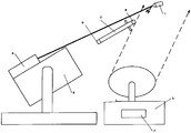
Die Erfindung ist nachfolgend an Hand eines in der Zeichnung schematisch dargestellten Ausführungsbeispiels einer Anordnung zur Durchführung des Verfahrens zur Bekämpfung eines Artilleriegeschosses mittels eines Lenkflugkörpers beschrieben.The invention is described below with reference to an embodiment of an arrangement schematically illustrated in the drawing for carrying out the method for controlling an artillery projectile by means of a guided missile.
Zur Erfassung eines Artilleriegeschosses
Mit Hilfe einer solchen Anordnung wird also die angreifende Artilleriemunition in Form von Mörsergranaten oder Raketen über das Zielerfassungs-Radar
Gemäß einer nicht erfindungsgemäßen Ausgestaltung kann der Laserstrahler
Die gerichtet ausgesandte Laserstrahlung dient also jeweils der Beleuchtung, also der Zielmarkierung, so dass die vom Ziel zurück gestreute Laser-Strahlung von einem Laser- Suchkopf
Mittels des genannten Verfahrens wird eine Flugkörperlenkung mit sehr hoher Präzision erreicht, so dass ein direkter Treffer des angreifenden Geschosses erzielbar ist.By means of said method, a missile guidance is achieved with very high precision, so that a direct hit of the attacking projectile can be achieved.
Es kann aber auch eine Mikrowellen-Strahlung mit Wellenlängen im Millimeterbereich zur Flugkörperlenkung verwendet werden. Eine solche Übertragung bietet den Vorteil der besseren Transmission einer elektromagnetischen Strahlung gegenüber Laserstrahlung auch bei ungünstigen Atmosphäreneigenschaften.However, it is also possible to use microwave radiation with wavelengths in the millimeter range for the guidance of the missile. Such a transmission offers the advantage of better transmission of electromagnetic radiation to laser radiation even with unfavorable atmospheric properties.
BezugszeichenlisteLIST OF REFERENCE NUMBERS
- 11
- Artilleriegeschossesartillery shell
- 22
- Flugkörpermissile
- 33
- ZielerfassungsradarTarget acquisition radar
- 55
- Lenkflugkörper-AbschussbehälterMissile launch container
- 66
- Laser-ZieltrackerLaser Target Tracker
- 77
- Computercomputer
- 88th
- Laser-SuchkopfLaser seeker
- 99
- Laser-EmpfängerLaser receiver
Claims (1)
Priority Applications (2)
| Application Number | Priority Date | Filing Date | Title |
|---|---|---|---|
| DE102007049438.8A DE102007049438B4 (en) | 2007-10-16 | 2007-10-16 | Method for the defense of ballistic missiles with the help of guided missiles |
| EP08018015A EP2051039A1 (en) | 2007-10-16 | 2008-10-15 | Method and assembly for defending against ballistic missiles with the help of diverting missiles |
Applications Claiming Priority (1)
| Application Number | Priority Date | Filing Date | Title |
|---|---|---|---|
| DE102007049438.8A DE102007049438B4 (en) | 2007-10-16 | 2007-10-16 | Method for the defense of ballistic missiles with the help of guided missiles |
Publications (2)
| Publication Number | Publication Date |
|---|---|
| DE102007049438A1 DE102007049438A1 (en) | 2009-04-23 |
| DE102007049438B4 true DE102007049438B4 (en) | 2018-10-31 |
Family
ID=40328440
Family Applications (1)
| Application Number | Title | Priority Date | Filing Date |
|---|---|---|---|
| DE102007049438.8A Expired - Fee Related DE102007049438B4 (en) | 2007-10-16 | 2007-10-16 | Method for the defense of ballistic missiles with the help of guided missiles |
Country Status (2)
| Country | Link |
|---|---|
| EP (1) | EP2051039A1 (en) |
| DE (1) | DE102007049438B4 (en) |
Families Citing this family (7)
| Publication number | Priority date | Publication date | Assignee | Title |
|---|---|---|---|---|
| US8833232B1 (en) * | 2011-11-30 | 2014-09-16 | Drs Sustainment Systems, Inc. | Operational control logic for harmonized turret with gimbaled sub-systems |
| DE102015009200A1 (en) * | 2015-07-15 | 2017-01-19 | Diehl Bgt Defence Gmbh & Co. Kg | Energy system and weapon system |
| DE102016121698A1 (en) | 2016-11-11 | 2018-05-17 | Rheinmetall Waffe Munition Gmbh | Method and defense system to combat targets and threats |
| CN109595985B (en) * | 2018-10-08 | 2024-03-15 | 中国人民解放军空军预警学院雷达士官学校 | Radar and artillery anti-target correcting device and method |
| CN111721167A (en) * | 2020-05-19 | 2020-09-29 | 李超 | Aviation computer radar guidance system |
| IL281535B2 (en) | 2021-03-11 | 2025-03-01 | Elta Systems Ltd | Active protection against beam-riding guided munition |
| CN115420147A (en) * | 2022-07-19 | 2022-12-02 | 四川九洲防控科技有限责任公司 | Method, system, storage medium and electronic device for dynamic scheduling of devices |
Citations (8)
| Publication number | Priority date | Publication date | Assignee | Title |
|---|---|---|---|---|
| US5788178A (en) * | 1995-06-08 | 1998-08-04 | Barrett, Jr.; Rolin F. | Guided bullet |
| DE69411514T2 (en) * | 1993-11-25 | 1998-12-10 | Aerospatiale Societe Nationale Industrielle, Paris | Anti-aircraft system and anti-aircraft body therefor |
| US6204801B1 (en) * | 1998-08-14 | 2001-03-20 | Raytheon Company | System and method for obtaining precise missile range information for semiactive missile systems |
| DE10024320A1 (en) | 2000-05-17 | 2001-11-29 | Diehl Munitionssysteme Gmbh | Radar device for object self-protection |
| GB2380244A (en) * | 2001-08-13 | 2003-04-02 | Michael Joseph Zabrana | Automated defence system |
| DE10229273A1 (en) * | 2002-06-28 | 2004-01-29 | Diehl Munitionssysteme Gmbh & Co. Kg | Object self-protection device |
| EP1607710A1 (en) | 2004-06-18 | 2005-12-21 | Saab Ab | System for determining the target range for a laser guided weapon |
| DE102004030962A1 (en) * | 2004-06-26 | 2006-01-12 | Diehl Bgt Defence Gmbh & Co. Kg | Laser target illumination system for use with laser-guided ammunition uses laser shining beam directly onto target, and laser spot search head in projectile containing submunitions |
Family Cites Families (8)
| Publication number | Priority date | Publication date | Assignee | Title |
|---|---|---|---|---|
| US2557401A (en) * | 1945-01-10 | 1951-06-19 | Arma Corp | Remote control apparatus |
| US3677500A (en) * | 1952-11-10 | 1972-07-18 | Us Navy | Scanning interferometer-beam rider guidance system |
| DE2149729C3 (en) * | 1971-10-05 | 1978-12-07 | Precitronic Gesellschaft Fuer Feinmechanik Und Electronic Mbh, 2000 Hamburg | Guiding system with overlapping laser beams |
| DE2225837C1 (en) * | 1972-05-27 | 1999-07-08 | Raytheon Co | Receiving device for a semi-active radar guidance system |
| DE2922592C2 (en) | 1979-06-02 | 1981-11-26 | Messerschmitt-Bölkow-Blohm GmbH, 8000 München | Missile defense method |
| DE2931321C2 (en) * | 1979-08-02 | 1982-05-19 | Messerschmitt-Bölkow-Blohm GmbH, 8000 München | Method for the automatic guidance of a missile |
| DE3343604C2 (en) * | 1983-12-02 | 1986-05-22 | Messerschmitt-Bölkow-Blohm GmbH, 8012 Ottobrunn | Method and device for combating ground targets by means of a radar-guided missile |
| IL140232A (en) * | 2000-12-11 | 2010-04-29 | Rafael Advanced Defense Sys | Method and system for active laser imagery guidance of intercepting missiles |
-
2007
- 2007-10-16 DE DE102007049438.8A patent/DE102007049438B4/en not_active Expired - Fee Related
-
2008
- 2008-10-15 EP EP08018015A patent/EP2051039A1/en not_active Withdrawn
Patent Citations (8)
| Publication number | Priority date | Publication date | Assignee | Title |
|---|---|---|---|---|
| DE69411514T2 (en) * | 1993-11-25 | 1998-12-10 | Aerospatiale Societe Nationale Industrielle, Paris | Anti-aircraft system and anti-aircraft body therefor |
| US5788178A (en) * | 1995-06-08 | 1998-08-04 | Barrett, Jr.; Rolin F. | Guided bullet |
| US6204801B1 (en) * | 1998-08-14 | 2001-03-20 | Raytheon Company | System and method for obtaining precise missile range information for semiactive missile systems |
| DE10024320A1 (en) | 2000-05-17 | 2001-11-29 | Diehl Munitionssysteme Gmbh | Radar device for object self-protection |
| GB2380244A (en) * | 2001-08-13 | 2003-04-02 | Michael Joseph Zabrana | Automated defence system |
| DE10229273A1 (en) * | 2002-06-28 | 2004-01-29 | Diehl Munitionssysteme Gmbh & Co. Kg | Object self-protection device |
| EP1607710A1 (en) | 2004-06-18 | 2005-12-21 | Saab Ab | System for determining the target range for a laser guided weapon |
| DE102004030962A1 (en) * | 2004-06-26 | 2006-01-12 | Diehl Bgt Defence Gmbh & Co. Kg | Laser target illumination system for use with laser-guided ammunition uses laser shining beam directly onto target, and laser spot search head in projectile containing submunitions |
Also Published As
| Publication number | Publication date |
|---|---|
| EP2051039A1 (en) | 2009-04-22 |
| DE102007049438A1 (en) | 2009-04-23 |
Similar Documents
| Publication | Publication Date | Title |
|---|---|---|
| DE102007049438B4 (en) | Method for the defense of ballistic missiles with the help of guided missiles | |
| US20140102288A1 (en) | Active protection system | |
| DE10117007A1 (en) | Method and device for protecting mobile military equipment | |
| US20080291075A1 (en) | Vehicle-network defensive aids suite | |
| EP2645047A1 (en) | Low-altitude low-speed small target intercepting method based on firing table fitting | |
| US20190195601A1 (en) | A method for neutralizing a threat | |
| US20170307334A1 (en) | Apparatus and System to Counter Drones Using a Shoulder-Launched Aerodynamically Guided Missile | |
| EP3538835B1 (en) | Method and defence system for combating threats | |
| RU2527610C2 (en) | Two-stage antitank guided missile | |
| DE102012000709A1 (en) | Method for repelling an approaching ballistic missile and interceptor system | |
| CN112197656B (en) | Guidance bullet based on microsystem | |
| US9671200B1 (en) | Kinetic air defense | |
| DE2922592C2 (en) | Missile defense method | |
| RU2483273C1 (en) | Complex homing head (versions) | |
| RU105422U1 (en) | RECOGNITION-FIRE COMPLEX OF TANK WEAPONS | |
| RU2601241C2 (en) | Ac active protection method and system for its implementation (versions) | |
| Banasik | Trends in the development of Russian precision-guided weapons | |
| RU2722709C1 (en) | Method of destroying military equipment with controlled ammunition | |
| Asar et al. | Review of artillery smart ammunition | |
| RU2435127C1 (en) | Method to control cannon firing by controlled projectile | |
| Fesenko | Future trends in precision arms development. | |
| Rethik | PGMs and development in India | |
| DE102013006812B4 (en) | Guided missile and active system, comprising the guided missile | |
| Kariya et al. | New technology transforms tactics in afghanistan [warfare technology] | |
| SE2200135A1 (en) | ADAPTIVE SHOT PATTERNS |
Legal Events
| Date | Code | Title | Description |
|---|---|---|---|
| OP8 | Request for examination as to paragraph 44 patent law | ||
| R081 | Change of applicant/patentee |
Owner name: MBDA DEUTSCHLAND GMBH, DE Free format text: FORMER OWNER: LFK-LENKFLUGKOERPERSYSTEME GMBH, 86529 SCHROBENHAUSEN, DE Effective date: 20130307 |
|
| R002 | Refusal decision in examination/registration proceedings | ||
| R006 | Appeal filed | ||
| R008 | Case pending at federal patent court | ||
| R082 | Change of representative |
Representative=s name: ISARPATENT - PATENT- UND RECHTSANWAELTE BEHNIS, DE Representative=s name: ISARPATENT - PATENT- UND RECHTSANWAELTE BARTH , DE Representative=s name: ISARPATENT - PATENTANWAELTE- UND RECHTSANWAELT, DE |
|
| R019 | Grant decision by federal patent court | ||
| R020 | Patent grant now final | ||
| R119 | Application deemed withdrawn, or ip right lapsed, due to non-payment of renewal fee |