KR20230074807A - Passing the alignment information of the 3D tomography from the first set of images to the second set of images - Google Patents
Passing the alignment information of the 3D tomography from the first set of images to the second set of images Download PDFInfo
- Publication number
- KR20230074807A KR20230074807A KR1020237014482A KR20237014482A KR20230074807A KR 20230074807 A KR20230074807 A KR 20230074807A KR 1020237014482 A KR1020237014482 A KR 1020237014482A KR 20237014482 A KR20237014482 A KR 20237014482A KR 20230074807 A KR20230074807 A KR 20230074807A
- Authority
- KR
- South Korea
- Prior art keywords
- cross
- sectional images
- alignment information
- imaging
- sectional
- Prior art date
- Legal status (The legal status is an assumption and is not a legal conclusion. Google has not performed a legal analysis and makes no representation as to the accuracy of the status listed.)
- Ceased
Links
Images


Classifications
-
- G06T11/003—
-
- G—PHYSICS
- G06—COMPUTING OR CALCULATING; COUNTING
- G06T—IMAGE DATA PROCESSING OR GENERATION, IN GENERAL
- G06T12/00—Tomographic reconstruction from projections
-
- G—PHYSICS
- G06—COMPUTING OR CALCULATING; COUNTING
- G06T—IMAGE DATA PROCESSING OR GENERATION, IN GENERAL
- G06T3/00—Geometric image transformations in the plane of the image
- G06T3/40—Scaling of whole images or parts thereof, e.g. expanding or contracting
- G06T3/4007—Scaling of whole images or parts thereof, e.g. expanding or contracting based on interpolation, e.g. bilinear interpolation
-
- G—PHYSICS
- G06—COMPUTING OR CALCULATING; COUNTING
- G06T—IMAGE DATA PROCESSING OR GENERATION, IN GENERAL
- G06T7/00—Image analysis
- G06T7/30—Determination of transform parameters for the alignment of images, i.e. image registration
- G06T7/33—Determination of transform parameters for the alignment of images, i.e. image registration using feature-based methods
-
- G—PHYSICS
- G06—COMPUTING OR CALCULATING; COUNTING
- G06T—IMAGE DATA PROCESSING OR GENERATION, IN GENERAL
- G06T7/00—Image analysis
- G06T7/30—Determination of transform parameters for the alignment of images, i.e. image registration
- G06T7/38—Registration of image sequences
-
- G—PHYSICS
- G06—COMPUTING OR CALCULATING; COUNTING
- G06T—IMAGE DATA PROCESSING OR GENERATION, IN GENERAL
- G06T7/00—Image analysis
- G06T7/70—Determining position or orientation of objects or cameras
- G06T7/73—Determining position or orientation of objects or cameras using feature-based methods
-
- G—PHYSICS
- G06—COMPUTING OR CALCULATING; COUNTING
- G06T—IMAGE DATA PROCESSING OR GENERATION, IN GENERAL
- G06T2207/00—Indexing scheme for image analysis or image enhancement
- G06T2207/10—Image acquisition modality
- G06T2207/10056—Microscopic image
- G06T2207/10061—Microscopic image from scanning electron microscope
-
- G—PHYSICS
- G06—COMPUTING OR CALCULATING; COUNTING
- G06T—IMAGE DATA PROCESSING OR GENERATION, IN GENERAL
- G06T2207/00—Indexing scheme for image analysis or image enhancement
- G06T2207/10—Image acquisition modality
- G06T2207/10072—Tomographic images
-
- G—PHYSICS
- G06—COMPUTING OR CALCULATING; COUNTING
- G06T—IMAGE DATA PROCESSING OR GENERATION, IN GENERAL
- G06T2207/00—Indexing scheme for image analysis or image enhancement
- G06T2207/30—Subject of image; Context of image processing
- G06T2207/30108—Industrial image inspection
- G06T2207/30148—Semiconductor; IC; Wafer
-
- H—ELECTRICITY
- H01—ELECTRIC ELEMENTS
- H01J—ELECTRIC DISCHARGE TUBES OR DISCHARGE LAMPS
- H01J2237/00—Discharge tubes exposing object to beam, e.g. for analysis treatment, etching, imaging
- H01J2237/22—Treatment of data
- H01J2237/226—Image reconstruction
Landscapes
- Engineering & Computer Science (AREA)
- Physics & Mathematics (AREA)
- General Physics & Mathematics (AREA)
- Theoretical Computer Science (AREA)
- Computer Vision & Pattern Recognition (AREA)
- Analysing Materials By The Use Of Radiation (AREA)
Abstract
본 발명은 제1 이미지 세트로부터 제2 이미지 세트로 정렬 정보를 전달하는 것에 관한 것이다. 제1 이미징 모드에서 시간 Tai에서 촬영된 제1 단면 이미지 세트가 얻어진다. 제2 이미징 모드에서 Tai와는 상이한 시간 Tbj에서 촬영된 제2 단면 이미지 세트가 얻어진다. 제1 및 제2 이미지 세트를 얻는 것은 후속적으로 샘플의 단면 표면층을 제거하는 것과, 제1 이미징 모드 또는 제2 이미징 모드에서 샘플의 새로운 단면을 이미징하는 것을 포함한다. 제1 및 제2 단면 이미지 세트를 얻는 동안 제1 이미징 모드와 제2 이미징 모드 사이에서 전환이 수행된다. 정렬 정보는 정렬 정보의 시간 종속 보간을 포함하여 제1 세트의 이미지로부터 제2 세트로 전달된다.The present invention relates to passing alignment information from a first set of images to a second set of images. A first set of cross-sectional images taken at time Tai in the first imaging mode is obtained. In the second imaging mode, a second set of cross-sectional images taken at a time Tbj different from Tai is obtained. Acquiring the first and second sets of images includes subsequently removing the cross-sectional surface layer of the sample and imaging the new cross-section of the sample in either the first imaging mode or the second imaging mode. Switching between the first imaging mode and the second imaging mode is performed while acquiring the first and second cross-sectional image sets. Alignment information is passed from the first set of images to the second set including time dependent interpolation of the alignment information.
Description
본 발명은 슬라이스 및 이미지 접근법에서 2D 슬라이스로부터 3D 단층 촬영 데이터의 생성에 관한 것이다. 더 구체적으로, 본 발명은 예를 들어 집적 반도체 샘플과 같은, 예를 들어 샘플의 3D 체적 이미지를 얻기 위해 제1 이미지 세트로부터 제2 이미지 세트로 정렬 정보를 전달하는 방법에 관한 것이다. 더욱이, 본 발명은 대응 컴퓨터 프로그램 제품 및 대응 검사 디바이스에 관한 것이다.The present invention relates to the generation of 3D tomographic data from 2D slices in a slice and image approach. More specifically, the present invention relates to a method of transferring alignment information from a first set of images to a second set of images to obtain a 3D volumetric image of, for example, a sample, such as an integrated semiconductor sample. Moreover, the present invention relates to a corresponding computer program product and a corresponding testing device.
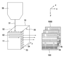
nm 스케일의 샘플로부터, 예를 들어 nm 스케일의 반도체 샘플로부터 3D 단층 촬영 데이터를 생성하는 통상적인 방법은 예를 들어 이중 빔 디바이스에 의해 정교하게 되는 소위 슬라이스 및 이미지 접근법이다. 이러한 장치에서, 2개의 입자 광학 시스템은 소정 각도로 배열된다. 제1 입자 광학 시스템은 주사 전자 현미경(SEM) 또는 예를 들어 헬륨 이온 현미경(HIM)과 같은 다른 하전 입자 현미경일 수 있다. 제2 입자 광학 시스템은 예를 들어 갈륨(Ga) 이온을 사용하는 집속 이온 빔 광학 시스템(FIB)일 수 있다. Ga 이온의 집속 이온 빔(FIB)은 샘플의 에지에서 층을 슬라이스별로 절단("밀링")하는 데 사용되고 모든 단면은 주사 전자 현미경(SEM) 또는 HIM을 사용하여 이미징된다. 2개의 입자 광학 시스템은 수직으로 또는 45° 내지 90°의 각도로 배향될 수도 있다. 도 1은 슬라이스 및 이미지 접근법의 개략도를 도시하고 있는데: y-방향으로 집속 이온 입자 빔(51)을 갖는 FIB 광학 컬럼(50)을 사용하고, x-y-평면에서 스캐닝하여, 반도체 샘플(10)을 통한 단면으로부터 얇은 층은 단면 이미지 평면(11)으로서 새로운 전방면(52)을 드러내기 위해 제거된다. 다음 단계에서, SEM 또는 HIM(도시되어 있지 않음)이 단면(11)의 전방면을 스캐닝 이미징하기 위해 사용된다. 본 예에서, SEM 광축은 z-방향에 평행하게 배향되고, x-y-평면에서의 스캐닝 이미징 라인(82)은 단면 이미지 평면(11)을 래스터 스캔하고 단면 이미지 또는 슬라이스(100)를 형성한다. 예를 들어, 전방면(53, 54)을 통한 이러한 접근법의 반복에 의해, 상이한 깊이의 샘플을 통한 2D 단면 이미지(1000)의 시퀀스가 얻어진다. 2개의 후속 이미지 슬라이스 사이의 거리(dz)는 1 nm 내지 10 nm일 수 있지만, 구체적인 용례에 따라 예를 들어, 최대 25 nm 또는 30 nm와 같은 다른 값이 또한 가능하다. 이들 2D 단면 이미지(1000)의 시퀀스로부터, 집적 반도체 구조체의 3D 이미지가 재구성될 수 있다. 집적 반도체 샘플 이외의 다른 샘플이 또한 조사될 수 있지만; 집적 반도체 샘플을 조사하는 것은 극도로 어려운 일이다.A conventional method for generating 3D tomographic data from a nm-scale sample, eg from a nm-scale semiconductor sample, is the so-called slice and image approach, elaborated by eg a dual beam device. In this device, two particle optical systems are arranged at an angle. The first particle optical system may be a scanning electron microscope (SEM) or other charged particle microscope such as, for example, a helium ion microscope (HIM). The second particle optical system may be, for example, a focused ion beam optical system (FIB) using gallium (Ga) ions. A focused ion beam (FIB) of Ga ions is used to slice-by-slice ("mill") the layers at the edges of the sample and all cross-sections are imaged using a scanning electron microscope (SEM) or HIM. The two particle optical systems may be oriented vertically or at an angle of 45° to 90°. 1 shows a schematic diagram of the slice and image approach: using an FIB
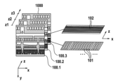
현대의 집적 회로의 더 미세한 상세와 더 작은 피처 크기로 인해, 3D 단층 촬영 이미지의 재구성은 여러 과제를 수반한다. 측면 스테이지 드리프트(lateral stage drifts) 또는 SEM 컬럼의 드리프트는 슬라이스로부터 슬라이스로 구조의 측면 위치에서 오프셋을 유발할 수도 있다. FIB 절단 속도의 변동은 교차 표면이 가변 거리에 있게 할 수도 있다. 이미지 왜곡은 예를 들어 핀 쿠션 또는 전단 왜곡을 갖는 단면 이미지로 이어질 수도 있다. 도 2는 x-y 단면 이미지의 시퀀스로부터 x-z-슬라이스의 재구성의 예를 도시하고 있다. 단순화를 위해, 2D 단면 이미지(1000)의 시퀀스의 z-위치(z1, z2, z3)에서 단지 3개의 단면 이미지(100.1, 100.2, 100.3)만이 도시되어 있다. 랜덤 스테이지 또는 SEM 드리프트는 z 방향으로 연장되는 금속 라인(101)의 인공적으로 향상된 라인 에지 거칠기 또는 z-방향에 평행하게 연장되는 금속 라인(102)의 폭의 큰 변동을 야기한다.Due to the finer details and smaller feature sizes of modern integrated circuits, reconstruction of 3D tomographic images presents several challenges. Lateral stage drifts, or drift of the SEM column, may cause an offset in the lateral position of the structure from slice to slice. Fluctuations in the FIB cutting speed may cause the intersecting surfaces to be at variable distances. Image distortion may lead to cross-sectional images having, for example, pin cushion or shear distortion. Figure 2 shows an example of reconstruction of an x-z-slice from a sequence of x-y cross-section images. For simplicity, only three cross-section images 100.1, 100.2, 100.3 are shown at z-positions z1, z2, z3 of the sequence of
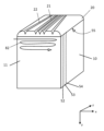
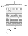
소위 기점(fiducials)의 도움으로 각각의 슬라이스의 측면 위치 뿐만 아니라 층으로부터 층까지의 거리를 도출하는 것이 통상적인 방법이다. US 9,633,819 B2는 샘플의 상부에 노출된 안내 구조("기점")에 기초하는 정렬 방법을 개시하고 있다. 도 3a 및 도 3b는 기점과의 정렬을 도시하고 있다. 아래에서 더 상세히 설명되는 바와 같이, 마커 구조(21, 22)가 교차점(52, 53, 54)의 FIB 절단이 시작되기 전에 단면의 방향에 수직인 샘플의 상부에 퇴적 재료(20)로 형성된다. 단면을 슬라이싱 및 이미징한 후, 각각의 단면 이미지는 기점 또는 정렬 마커(21, 22)의 단면 이미지 세그먼트(25, 27)를 또한 포함한다. 제1 중앙 마커(21)는 슬라이스 사이의 측면 정렬을 수행하는 데 사용되고, 반면 2개의 단면 이미지 세그먼트(27)로 이어지는 2개의 외부, 제2 마커(22) 사이의 거리는 각각의 슬라이스 사이의 거리를 계산하는 데 사용된다.It is common practice to derive the distance from layer to layer as well as the lateral position of each slice with the aid of so-called fiducials. US 9,633,819 B2 discloses an alignment method based on a guiding structure ("fiducial") exposed on top of the sample. 3A and 3B show alignment with fiducials. As described in more detail below,
그러나, 관심 구조와 함께 안내 구조 또는 기점을 이미징하는 것은 여러 단점을 갖는다:However, imaging the guiding structure or fiducial together with the structure of interest has several disadvantages:
첫째, 수용 가능한 정렬을 얻기 위해, 관심 구조보다 더 큰 픽셀 크기로 기점을 이미징하는 것으로 충분할 수도 있다. 기점은 예를 들어 4 nm 픽셀 크기 또는 심지어 더 큰 크기로 이미징될 수 있고, 반면 관심 구조는 예를 들어 2 nm 이하의 픽셀 크기를 필요로 한다. 하나의 스캔으로부터 하나의 이미지로 양자 모두를 수용하는 것이 가능하지 않기 때문에, 관심 구조와 기점의 모두는 2 nm 픽셀 크기로 이미징되어야 해서 처리량의 저하를 야기한다. 예를 들어, 2 nm 픽셀 크기로 하나의 픽셀을 이미징하는 것은 몇 분, 예를 들어 1 내지 2분 또는 심지어 더 길게 소요될 수 있다.First, to obtain an acceptable alignment, it may be sufficient to image the fiducial at a larger pixel size than the structure of interest. Fiducials can be imaged with, for example, 4 nm pixel sizes or even larger, whereas structures of interest require, for example, 2 nm or smaller pixel sizes. Since it is not possible to accommodate both in one image from one scan, both the structure of interest and the fiducial must be imaged with a 2 nm pixel size, resulting in a decrease in throughput. For example, imaging one pixel with a 2 nm pixel size may take several minutes, such as 1 to 2 minutes or even longer.
둘째, 때때로 작은 픽셀 크기를 갖는 작은 영역을 얻지만, 다른 한편으로는 주변을 보여주는 몇몇 더 거친 개요 이미지를 갖는 것이 바람직하다.Second, sometimes it is desirable to get a small area with a small pixel size, but on the other hand to have some coarser overview images showing the surroundings.
셋째, 관심 구조에 대한 최적의 이미징 조건은 기점을 위해 요구되는 최적의 이미징 조건에 모순될 수도 있고, 공통의 이미징 조건을 찾기 위해 - 이것이 조금이라도 가능하다면 - 양자 모두에서 절충해야 할 것이다. 마지막으로 관심 구조가 최선으로 요구되기 때문에, 이는 결국 도구의 이미징 성능에 대한 나쁜 절충안이다.Third, the optimal imaging conditions for a structure of interest may contradict the optimal imaging conditions required for fiducials, and to find common imaging conditions—if this is at all possible—needs to be compromised in both. Finally, since the structure of interest is best demanded, this is in the end a bad compromise for the imaging performance of the tool.
해결책으로서 상이한 이미징 조건을 갖는 2개의 이미지를 서로 직후에 촬영하는 것이 관련 기술 분야에 제안되어 있다. 이 접근법은 "FIBICS 키 프레임 접근법"으로서 알려져 있으며 US 2014/0226003 A1에 설명되어 있다. 상기 접근법에 따르면, 제1 단면 이미지("키 프레임 이미지")가 제1 이미징 픽셀 크기로 얻어지고, 이 제1 단면 이미지는 관심 구조에 추가하여 기점의 세그먼트를 포함한다. 그 직후, 제2 단면 이미지가 단면 이미지에서 관심 구조를 양호하게 상세히 보여주기에 적합한 제2 이미징 픽셀 크기로 얻어진다. 제1 단면 이미지에서 기점의 위치가 결정되고, 따라서 관심 구조의 위치가 또한 원리적으로 제1 단면 이미지와 제2 단면 이미지의 모두에서 알려진다. 이들 이미징 조건 사이의 전환은 여러 번 수행된다.As a solution, it is proposed in the related art to take two images with different imaging conditions immediately after each other. This approach is known as the "FIBICS key frame approach" and is described in US 2014/0226003 A1. According to this approach, a first cross-sectional image ("key frame image") is obtained with a first imaging pixel size, which first cross-sectional image includes segments of fiducials in addition to the structure of interest. Immediately thereafter, a second cross-sectional image is obtained with a second imaging pixel size suitable for good detailing of the structure of interest in the cross-sectional image. The location of the fiducial is determined in the first cross-sectional image, and thus the location of the structure of interest is in principle also known in both the first and second cross-sectional images. Switching between these imaging conditions is performed multiple times.
그러나, 이 접근법에 따른 이미징 조건 사이의 전환은 또한 단점을 갖는데: 하나의 문제는 키 프레임 이미지 내의 정렬 기점이 제2 단면 이미지(들)의 관심 구조가 아닌 다른 시간 인스턴스에서 이미징된다는 것이다. 특히, 이미징 중에 밀링이 계속되면 이는 관심 구조에 대한 3D 단층 촬영 데이터의 적절한 생성에 체계적인 오류를 야기한다.However, switching between imaging conditions according to this approach also has disadvantages: One problem is that the alignment fiducials in the key frame image are imaged at different time instances than the structure of interest in the second cross-section image(s). In particular, continued milling during imaging causes systematic errors in the proper generation of 3D tomographic data for the structure of interest.
본 발명의 목적은 nm 스케일의 샘플로부터 3D 단층 촬영 데이터의 생성을 개선하는 것이다.An object of the present invention is to improve the generation of 3D tomographic data from samples on the nm scale.
다른 목적은 3D 단층 촬영 데이터 세트를 생성할 때 단면 이미지의 정렬을 개선하는 것이다(이미지 정합을 수행함).Another objective is to improve alignment of cross-sectional images (performing image registration) when generating 3D tomography data sets.
다른 목적은 하나의 이미지 세트로부터 상이한 픽셀 크기 및/또는 다른 센서로 상이한 시간 인스턴스에 촬영될 수도 있는 다른 이미지 세트로 정렬 정보를 전달하는 것이다.Another purpose is to convey alignment information from one set of images to another set of images that may be taken at different time instances with different pixel sizes and/or different sensors.
목적은 독립항에 의해 해결된다. 종속항은 다른 실시예에 관한 것이다.Objects are solved by the independent claims. Dependent claims relate to other embodiments.
본 특허 출원은 그 전체 범주에서 그 개시내용이 참조에 의해 본 특허 출원에 합체되어 있는 2020년 11월 4일자로 출원된 미국 가특허 출원 제63/109,447호의 우선권을 주장한다.This patent application claims priority to US Provisional Patent Application Serial No. 63/109,447, filed on November 4, 2020, the disclosure of which in its entirety is hereby incorporated by reference into this patent application.
제1 양태에 따르면, 본 발명은 3D 단층 촬영에서 제1 이미지 세트로부터 제2 이미지 세트로 정렬 정보를 전달하는 방법에 관한 것으로서, 이하의 단계:According to a first aspect, the present invention relates to a method of transferring alignment information from a first image set to a second image set in 3D tomography, comprising the following steps:
- 시간 Tai에서 촬영되는 제1 단면 이미지 세트를 제1 이미징 모드에서 얻는 단계;- obtaining in a first imaging mode a first set of cross-sectional images taken at time Tai;
- 시간 Tai와는 상이한 시간 Tbj에서 촬영되는 제2 단면 이미지 세트를 제2 이미징 모드에서 얻는 단계로서;- obtaining in a second imaging mode a second set of cross-sectional images taken at a time Tbj different from time Tai;
여기서 제1 및 제2 단면 이미지 세트를 얻는 단계는 후속적으로 특히 집속 이온 빔을 사용하여 샘플의 단면 표면층을 제거하여 이미징을 위해 접근 가능한 새로운 단면을 만드는 단계, 및 특히 하전 입자 빔으로 제1 이미징 모드 또는 제2 이미징 모드에서 샘플의 새로운 단면을 이미징하는 단계를 포함하고,Obtaining first and second sets of cross-sectional images herein includes subsequently removing a cross-sectional surface layer of the sample, in particular with a focused ion beam, to make a new cross-section accessible for imaging, and in particular with a first imaging with a charged particle beam. imaging a new cross-section of the sample in either mode or a second imaging mode;
제1 및 제2 단면 이미지 세트를 얻는 동안 제1 이미징 모드와 제2 이미징 모드 사이에서 전환이 수행되는, 제1 및 제2 단면 이미지 세트를 얻는 단계;obtaining first and second cross-sectional image sets, wherein switching is performed between the first imaging mode and the second imaging mode while obtaining the first and second cross-sectional image sets;
- 제1 세트의 단면 이미지에 포함된 정렬 정보를 결정하는 단계; 및- determining the alignment information contained in the first set of cross-sectional images; and
- 제1 세트의 단면 이미지의 정렬 정보를 제2 세트의 단면 이미지로 전달하는 단계를 포함하고,- conveying the alignment information of the first set of cross-sectional images to the second set of cross-sectional images;
정렬 정보를 전달하는 단계는 정렬 정보의 시간 종속 보간을 포함한다.Passing the alignment information includes time dependent interpolation of the alignment information.
실시예에 따르면, 제1 이미징 모드에서 이미징되는 샘플의 영역 또는 부분은 제2 이미징 모드에서 이미징되는 샘플의 영역 또는 부분을 완전히 또는 부분적으로 포함한다. 그러나, 이는 반드시 그러한 것은 아니다. 예에서, 양 이미징 모드에서 관심 구조가 이미징되지만; 관심 구조는 제2 이미징 모드에서만 고해상도로 이미징되고, 제1 이미징 모드에서는 그렇지 않다. 여전히, 제1 이미징 모드에서의 이미징 조건은 예를 들어 기점에 기초하여 정렬 정보를 결정하기 위해 충분하다. 예에서, 기점은 제1 이미징 모드에서 이미징되지만, 제2 이미징 모드에서는 이미징되지 않고; 더욱이, 관심 구조는 제2 이미징 모드에서만 이미징된다.According to an embodiment, the area or portion of the sample imaged in the first imaging mode completely or partially includes the area or portion of the sample imaged in the second imaging mode. However, this is not necessarily the case. In an example, a structure of interest is imaged in both imaging modes; The structure of interest is imaged at high resolution only in the second imaging mode, but not in the first imaging mode. Still, the imaging conditions in the first imaging mode are sufficient to determine alignment information based on fiducials, for example. In an example, the fiducial is imaged in the first imaging mode but not imaged in the second imaging mode; Moreover, the structure of interest is imaged only in the second imaging mode.
본 발명의 설명 내에서, 용어 "단면 이미지"는 넓은 의미로 해석되어야 하는데: 단면 이미지는 전체 단면 이미지일 수 있다. 대안적으로, 단면 이미지는 전체 단면 이미지의 단지 부분 또는 영역일 수 있다. 예에서, 전체 단면 이미지는 상이한 시간에 이미징된 샘플의 상이한 부분 또는 영역을 모두 보여주는 2개의 상이한 단면 이미지를 포함할 수 있다. 따라서, 샘플의 제1 부분은 제1 이미징 모드에서 이미징되고 제2 부분은 제2 이미징 모드에서 이미징되는데; 이러한 종류의 이미징/2개의 상이한 이미징 모드 사이의 전환은 입자 빔에 의한 하나의 래스터 스캔 동안 또는 상이한(예를 들어, 후속) 래스터 스캔 동안에 수행될 수 있다(하나의 래스터 스캔은 예를 들어 상부 좌측 코너로부터 하부 우측 코너로 샘플 위에서 입자 빔의 이동임).Within the description of the present invention, the term “cross-sectional image” should be interpreted in a broad sense: a cross-sectional image may be an entire cross-sectional image. Alternatively, the cross-sectional image may be just a portion or region of the full cross-sectional image. In an example, a full cross-sectional image may include two different cross-sectional images that both show different parts or regions of the sample imaged at different times. Thus, a first portion of the sample is imaged in the first imaging mode and a second portion is imaged in the second imaging mode; Imaging of this kind/switching between two different imaging modes can be performed during one raster scan with the particle beam or during a different (e.g. subsequent) raster scan (one raster scan e.g. upper left). is the movement of the particle beam over the sample from the corner to the lower right corner).
이 특허 출원 내에서 용어 "정렬 정보"는 용어 "위치 정보"와 동의어로 사용된다. 그러나, 용어 "정렬 정보"는 정보의 의도된 사용, 즉, 정렬 목적을 추가로 나타낸다.Within this patent application the term "alignment information" is used synonymously with the term "location information". However, the term “alignment information” further denotes the intended use of the information, ie for alignment purposes.
본 발명에 따르면, 제1 단면 이미지는 시간 Tai에서 촬영되고 제2 단면 이미지는 시간 Tbj에서 촬영되며, 시간 Tai는 시간 Tbj와는 상이하다. 달리 말하면, 제1 세트의 단면 이미지는 제2 세트에 속하는 단면 이미지와는 상이한 시간에 촬영된다. 인덱스 a는 제1 세트를 나타내고 인덱스 i는 제1 단면 이미지 세트의 구체적인 단면 이미지를 표시한다. 유사하게, 인덱스 b는 제2 세트를 나타내고 인덱스 j는 제2 단면 이미지 세트의 구체적인 단면 이미지를 표시한다. 제1 단면 이미지 세트 및 제2 단면 이미지 세트가 각각 동일한 수의 단면 이미지를 포함하는 것이 가능하지만; 이는 그렇지 않거나 또는 적어도 정확히 그렇지 않은 것도 또한 가능하다. 시간 Tai와 시간 Tbj는 전체적으로 규칙적인 "시간 패턴"을 형성하는 것이 가능하지만; 이는 그렇지 않은 것도 또한 가능하다. 제1 단면 이미지 세트는 예를 들어, 100, 200, 300 또는 400개 이상의 단면 이미지를 포함할 수 있고, 제2 단면 이미지 세트도 마찬가지일 수 있다. 그러나, 제2 세트의 단면 이미지의 수는 적어도 제1 세트의 단면 이미지의 수인 것이 바람직하다. 예를 들어, 제2 세트를 구성하는 단면 이미지의 수는 제1 세트를 구성하는 단면 이미지의 수와 동일할 수 있거나 제2 세트의 단면 이미지의 수는 제1 세트의 단면 이미지의 수의 2배 또는 3배일 수 있다.According to the present invention, the first cross-section image is taken at time Tai and the second cross-section image is taken at time Tbj, and time Tai is different from time Tbj. In other words, cross-sectional images of the first set are taken at different times than cross-sectional images belonging to the second set. Index a indicates the first set and index i indicates a specific cross-sectional image of the first cross-sectional image set. Similarly, index b indicates the second set and index j indicates a specific cross-sectional image of the second cross-sectional image set. It is possible that the first set of cross-sectional images and the second set of cross-sectional images each include the same number of cross-sectional images; It is also possible that this is not the case or at least not exactly so. It is possible that time Tai and time Tbj form an overall regular “time pattern”; It is also possible that this is not the case. The first cross-sectional image set may include, for example, 100, 200, 300, or 400 or more cross-sectional images, and the second cross-sectional image set may be the same. However, it is preferable that the number of cross-sectional images in the second set is at least the number of cross-sectional images in the first set. For example, the number of cross-sectional images comprising the second set may be equal to the number of cross-sectional images comprising the first set, or the number of cross-sectional images of the second set may be twice the number of cross-sectional images of the first set. or 3 times.
본 발명에 따르면, 제1 및 제2 단면 이미지 세트를 얻는 동안 제1 이미징 모드와 제2 이미징 모드 사이에서 전환이 수행된다. 이는 제1 단면 이미지 세트가 완전히 얻어지고 이어서, 그 후에, 제2 단면 이미지 세트가 완전히 얻어지는 것이 제외된다는 것을 의미한다. 대신에, 제1 이미징 모드로부터 제2 이미징 모드로의 전환 뿐만 아니라 제2 이미징 모드로부터 제1 이미징 모드로의 역전환은 적어도 한 번, 바람직하게는 여러 번, 예를 들어 수백 번 수행된다.According to the present invention, switching between the first imaging mode and the second imaging mode is performed while acquiring the first and second cross-sectional image sets. This means that the first set of cross-sectional images is completely obtained and then the second set of cross-sectional images is excluded from being completely obtained. Instead, the switching from the first imaging mode to the second imaging mode as well as the reverse switching from the second imaging mode to the first imaging mode is performed at least once, preferably several times, eg hundreds of times.
일 실시예에 따르면, 제1 이미징 모드는 제2 이미징 모드와는 상이하다. 차이는 픽셀 크기, 이미징을 위한 다른 입자 광학 파라미터 및/또는 이미지를 얻기 위한 검출 시스템/검출 방법에 있을 수 있다. 그러나, 제1 이미징 모드와 제2 이미징 모드가 기술적으로 동일하지만, 제1 이미징 모드에서 샘플의 상이한 영역 또는 구조가 제2 이미징 모드에서 이미징되는 것도 또한 가능하다.According to one embodiment, the first imaging mode is different from the second imaging mode. Differences may be in pixel size, other particle optical parameters for imaging, and/or detection systems/detection methods for obtaining images. However, although the first imaging mode and the second imaging mode are technically the same, it is also possible that different areas or structures of the sample in the first imaging mode are imaged in the second imaging mode.
본 발명에 따르면, 제1 세트의 단면 이미지에 포함된 정렬 정보가 결정된다. 달리 말하면, 정렬 정보는 제1 세트의 단면 이미지에 대해 알려진 시간 Tai에 얻어진다. 원리적으로, 정렬 정보는 임의의 유형의 위치 정보일 수 있다. 정렬 정보는 주 주사 방향(x) 및/또는 부 주사 방향(y)에서의 측면 정렬에 대한 정보 및/또는 슬라이싱 방향(z)에서의 정렬 정보를 포함할 수 있다. 바람직하게는 방향 x, y 및 z는 서로 직교하지만, 다른 좌표계도 또한 가능하다. 예를 들어, 제1 세트의 키 프레임 단면 이미지에 포함된 정렬 정보가 결정되는 것이 가능하다. 이들 제1 단면 이미지(예를 들어, 키 프레임 단면 이미지)에서, 예를 들어 기점 또는 기점 세그먼트의 위치의 형태의 정렬 정보가 각각의 마커 또는 기점에 대해 측정된다. 공지의 이미지 처리 방법은 픽셀 내의 상기 위치 마커의 위치를 제공하고, 픽셀 크기를 인지하면, 이들 위치는 nm 단위로 위치로 변환될 수 있다. 따라서, 위치 정보인 정렬 정보는 알려진 시간 Tai에서 제1 세트의 단면 이미지에 대해 인지된다. 그에 대조적으로, 제2 세트의 단면 이미지에 가능하게 또한 포함되는 정렬 정보는 측정에 의해 결정되지 않는다. 심지어 정렬 정보가 제2 단면 이미지 세트에 포함될 필요가 없다. 대신에, 제1 세트의 단면 이미지로부터의 정렬 정보가 제2 세트의 단면 이미지로 전달된다. 정렬 정보를 전달하는 것은 정렬 정보의 시간 종속 보간을 포함한다. 이는 정렬 정보가 단지 측정된 위치/제1 세트의 단면 이미지로부터 결정된 정렬 정보로부터 계산된다는 것을 의미한다. 달리 말하면, 키 프레임 접근법을 고려하면, 정렬 정보는 키 프레임 이미지 자체로부터 결정되고, 키 프레임 이미지로부터 결정된 정렬 정보는 시간 종속 보간을 적용함으로써 관심 구조의 이미지로 전달된다. 용어 보간은 수학적 의미로 정의되는데: 주어진 이산 데이터(예를 들어, 측정값)에 대해, 이 데이터를 맵핑하는 연속 함수(소위 보간 함수)가 발견되어야 한다. 함수는 이어서 데이터를 보간하도록 설정된다. 시간 종속 보간은 단계별-연속 보간을 포함할 수 있다. 이어서, 연속 함수는 단지 단계별만 연속적이다. 더욱이, 시간 종속 보간은 공간의 1차원, 2차원 또는 3차원에서 수행될 수 있다. 따라서, 반드시 시간 종속 보간이 공간의 3차원 모두에서 수행되는 것은 아니다. 예가 아래에 설명될 것이다.According to the present invention, alignment information included in the first set of cross-sectional images is determined. In other words, alignment information is obtained at a known time T i for the first set of cross-sectional images. In principle, alignment information can be any type of location information. The alignment information may include information on lateral alignment in the main scanning direction (x) and/or sub-scanning direction (y) and/or alignment information in the slicing direction (z). Preferably the directions x, y and z are orthogonal to each other, but other coordinate systems are also possible. For example, it is possible to determine alignment information included in a first set of key frame cross-sectional images. In these first cross-sectional images (eg, key frame cross-sectional images), alignment information, for example in the form of fiducials or positions of fiducial segments, is measured for each marker or fiducial. Known image processing methods provide the positions of the position markers within pixels, and knowing the pixel size, these positions can be converted to positions in units of nm. Accordingly, alignment information, which is positional information, is recognized for the first set of cross-sectional images at a known time Tai. In contrast, the alignment information possibly also included in the second set of cross-sectional images is not determined by measurement. Even the alignment information need not be included in the second cross-sectional image set. Instead, alignment information from the first set of cross-sectional images is passed to the second set of cross-sectional images. Conveying the alignment information includes time dependent interpolation of the alignment information. This means that the alignment information is calculated from only the measured positions/alignment information determined from the first set of cross-sectional images. In other words, considering the key frame approach, the alignment information is determined from the key frame image itself, and the alignment information determined from the key frame image is transferred to the image of the structure of interest by applying time dependent interpolation. The term interpolation is defined in a mathematical sense: given discrete data (eg measured values), a continuous function mapping this data (so-called interpolation function) must be found. The function is then set to interpolate the data. Time-dependent interpolation may include step-continuous interpolation. Then, the continuous function is continuous only step by step. Furthermore, time-dependent interpolation can be performed in one, two or three dimensions of space. Thus, time-dependent interpolation is not necessarily performed in all three dimensions of space. An example will be explained below.
원리적으로, 이 시간 종속 보간은 상이한 슬라이스 및 이미지 작업흐름에 대해 작동한다. 정렬 정보는 예를 들어, 연속 밀링 모드 또는 밀링-정지-이미지 모드에서 전달될 수 있다. 이들 상이한 유형의 밀링 및 정렬 전달 계산에 대한 그 각각의 영향은 아래에 더 설명될 것이다.In principle, this time dependent interpolation works for different slice and image workflows. Alignment information can be conveyed, for example, in continuous milling mode or in milling-still-image mode. The impact of each of these different types of milling and alignment transfer calculations will be further explained below.
일 실시예에 따르면, 제1 세트의 단면 이미지는 제1 이미징 픽셀 크기를 갖고, 제2 세트의 단면 이미지는 제1 이미징 픽셀 크기와는 상이한 제2 이미징 픽셀 크기를 갖는다. 부가적으로 또는 대안적으로, 다른 파라미터들은 제1 이미징 모드와 제2 이미징 모드에서 상이한 것이 가능하다. 그러나, 다른 이미징 파라미터가 제1 이미징 모드와 제2 이미징 모드에서 동일하고 상이한 이미징 픽셀 크기가 이미징 모드 사이의 유일한 차이인 것도 또한 가능하다. 각각의 픽셀 크기의 차이는 정렬 정보를 전달할 때 고려된다.According to one embodiment, the first set of cross-sectional images has a first imaging pixel size and the second set of cross-sectional images has a second imaging pixel size different from the first imaging pixel size. Additionally or alternatively, it is possible that other parameters are different in the first and second imaging modes. However, it is also possible that the other imaging parameters are the same in the first imaging mode and the second imaging mode and the different imaging pixel size is the only difference between the imaging modes. Each pixel size difference is taken into account when conveying alignment information.
일 실시예에 따르면, 제1 이미징 픽셀 크기는 제2 이미징 픽셀 크기의 적어도 2배이다. 이미징 픽셀 크기를 예를 들어 나노미터 단위로 1차원으로 정의하는 것이 통상적이다. 예를 들어, 제1 이미징 픽셀 크기는 4 nm일 수 있고 제2 이미징 픽셀 크기는 2 nm일 수 있다. 픽셀의 2차 패턴을 참조하면, 제1 이미징 픽셀의 면적은 제2 이미징 픽셀의 면적의 적어도 4배이다. 픽셀 크기의 다른 정의도 또한 가능하다. 본 발명에 따른 처리량 이득은 제1 이미징 픽셀 크기와 제2 이미징 픽셀 크기 사이의 차이가 클수록, 또는 더 일반적으로는 제1 이미징 모드와 제2 이미징 모드가 더 상이할수록 더 강력해진다. 방법은 이미징의 상당한 속도 증가를 허용한다.According to one embodiment, the first imaging pixel size is at least twice the size of the second imaging pixel. It is common to define imaging pixel size in one dimension, for example in nanometers. For example, the first imaging pixel size may be 4 nm and the second imaging pixel size may be 2 nm. Referring to the secondary pattern of pixels, the area of the first imaging pixel is at least four times the area of the second imaging pixel. Other definitions of pixel size are also possible. The throughput gain according to the present invention becomes stronger the greater the difference between the first imaging pixel size and the second imaging pixel size, or more generally the more different the first and second imaging modes are. The method allows for a significant increase in speed of imaging.
일 실시예에 따르면, 제1 이미징 모드와 제2 이미징 모드 사이의 전환은 각각의 단면 이미지를 얻은 후에 엄격하게 교대로 수행된다. 이 경우, 이미지의 시퀀스는 예를 들어 Ta1, Tb1, Ta2, Tb2, Ta3, Tb3 …이다. 예에서, 2개의 후속 시간 인스턴스 Tai 및 Tai+1 사이의 시간 간격은 제1 단면 이미지 세트 내에서 일정하다. 예에서, 2개의 후속 시간 인스턴스 Tbj 및 Tbj+1 사이의 시간 간격은 제2 단면 이미지 세트의 각각의 j에 대해 일정하다. 2개의 후속 제1 단면 이미지 사이에서 정확히 시간별로 제2 단면 이미지를 촬영하는 것이 가능하다. 그러나, 이는 반드시 그러한 것은 아니다.According to one embodiment, switching between the first imaging mode and the second imaging mode is strictly alternated after obtaining each cross-sectional image. In this case, the sequence of images is for example Ta1, Tb1, Ta2, Tb2, Ta3, Tb3... am. In the example, the time interval between the two subsequent time instances Tai and Tai+1 is constant within the first set of cross-sectional images. In the example, the time interval between the two subsequent time instances Tbj and Tbj+1 is constant for each j of the second set of cross-sectional images. It is possible to take a second cross-sectional image exactly in time between two subsequent first cross-sectional images. However, this is not necessarily the case.
일 실시예에 따르면, 정렬 정보를 결정하는 것은 기점의 위치를 결정하는 것을 포함한다. 이는 정렬 정보를 결정하기 위한 잘 알려진 접근법이다.According to one embodiment, determining the alignment information includes determining a location of a fiducial. This is a well-known approach for determining alignment information.
일 실시예에 따르면, 기점은 깊이 방향(슬라이싱 방향)으로 정확하게 신장하는 평행한 기점의 세트 및 깊이 방향(슬라이싱 방향)으로 비스듬히 신장하는 비평행한 기점의 세트를 포함한다. 이러한 유형의 기점은 예를 들어, US 2014/0226003 A1에 나타나 있으며 이 출원의 도 3a에도 또한 나타나 있다. 예에서, 평행한 기점의 세트는 적어도 2개의 기점, 예를 들어 정확히 2개, 3개, 4개 이상의 기점을 포함한다. 깊이 방향(슬라이싱 방향)에 경사지게 또는 비스듬히 신장하는 비평행한 기점의 세트는 예를 들어 깊이 방향(슬라이싱 방향)에 대칭적으로 제공될 수 있는 정확히 2개의 기점을 포함할 수 있다. 이 기하학 형상은 정렬 정보 또는 위치 정보의 간단한 결정을 허용한다.According to one embodiment, the fiducials include a set of parallel fiducials extending exactly in the depth direction (slicing direction) and a set of non-parallel fiducials extending obliquely in the depth direction (slicing direction). Fiducials of this type are shown, for example, in US 2014/0226003 A1 and are also shown in FIG. 3a of this application. In an example, the set of parallel fiducials includes at least two fiducials, eg exactly two, three, four or more fiducials. The set of non-parallel fiducials extending obliquely or obliquely in the depth direction (slicing direction) may include exactly two fiducials, which may be provided symmetrically in the depth direction (slicing direction), for example. This geometry allows simple determination of alignment information or positional information.
일 실시예에 따르면, 제1 및 제2 단면 이미지 세트를 얻는 것은 연속 밀링 모드에서 수행된다. 연속 밀링 모드에서, 밀링 프로세스는 단면 이미지를 얻는 동안 계속된다. 단면 이미지를 얻기 위한 정지는 없다. 밀링 속도는 바람직하게는 일정하도록 선택된다. 연속 밀링 모드의 경우, 정렬 정보 또는 기점 위치는 시간의 평활 함수로 가정될 수 있고, 관심 구조를 보여주는 제2 단면 이미지에 대한 정렬 마커 또는 기점의 요구 위치는 인지된 위치를 사용하여 시간 종속 보간에 의해 결정될 수 있다. 일 예에서, 정렬 정보를 전달하는 것은 제1 세트의 단면 이미지가 얻어질 때의 시간 Tai의 지점에 기초하여 제2 세트의 단면 이미지가 얻어질 때의 시간 Tbj의 지점에 대한 상기 기점의 위치의 시간 종속 보간을 포함한다. 이 시간 종속 보간은 연속 밀링과 그를 위해 따라서 기점의 가변 위치를 고려하지만, 스테이지의 가능한 드리프트 및/또는 이미징 컬럼(예를 들어, SEM 또는 HIM 컬럼)의 드리프트를 또한 고려한다. 예에 따르면, 시간 종속 보간은 선형 보간이다. 많은 경우에 이 매우 간단한 형태의 보간이 우수한 정렬 결과를 얻기 위해 충분한 것으로 입증되었다.According to one embodiment, acquiring the first and second sets of cross-sectional images is performed in a continuous milling mode. In continuous milling mode, the milling process continues while obtaining cross-sectional images. There is no stop to obtain cross-sectional images. The milling speed is preferably chosen to be constant. In the case of continuous milling mode, the alignment information or fiducial positions can be assumed as a smoothing function of time, and the desired positions of alignment markers or fiducials for a second cross-sectional image showing the structure of interest are subjected to time-dependent interpolation using the recognized positions. can be determined by In one example, conveying the alignment information is the position of the fiducial relative to the point at time Tbj when the second set of cross-sectional images is obtained based on the point at time Tai when the first set of cross-sectional images is obtained. Include time-dependent interpolation. This time-dependent interpolation takes into account continuous milling and thus the variable position of the fiducials for it, but also takes into account possible drift of the stage and/or drift of the imaging column (eg SEM or HIM column). According to an example, the time dependent interpolation is a linear interpolation. In many cases this very simple form of interpolation has proven sufficient to obtain good alignment results.
일 실시예에 따르면, 2개의 단면 이미지를 촬영하는 사이의 시간 간격은 일정하다. 예에서, 이는 동일한 세트의 2개의 후속 단면 이미지에 대해 성립하지만, 부가적으로, 이 요구 사항은 상이한 세트에 속하는 2개의 후속 단면 이미지에 대해서도 또한 충족될 수 있다. 일정한 시간 간격을 적용하는 것은 보간을 용이하게 하고 또한 복수의 단면 이미지로부터 전체 이미지 정합을 용이하게 한다.According to one embodiment, a time interval between capturing two cross-sectional images is constant. In an example, this holds for two subsequent cross-sectional images of the same set, but additionally, this requirement may also be met for two subsequent cross-sectional images belonging to different sets. Applying a constant time interval facilitates interpolation and also facilitates global image registration from multiple cross-sectional images.
일 실시예에 따르면, 정렬 정보는 측면 정렬 정보 및/또는 깊이 정렬 정보이다. 이어서, 시간 종속 보간은 또한 시간 종속 측면 보간 및/또는 시간 종속 깊이 보간을 칭할 수 있다. 정렬 정보는 예를 들어, 상이한 기점을 참조함으로써 측면 위치에 대해 및 깊이 위치에 대해 개별적으로 결정될 수 있다. 이는 데이터 분석 및 이미지 처리 절차를 용이하게 할 수 있다.According to one embodiment, the alignment information is lateral alignment information and/or depth alignment information. Then, time-dependent interpolation can also refer to time-dependent lateral interpolation and/or time-dependent depth interpolation. Alignment information can be determined separately for the lateral position and for the depth position, for example by referring to different fiducials. This can facilitate data analysis and image processing procedures.
일 실시예에 따르면, 제1 및 제2 단면 이미지 세트를 얻는 것은 밀링-정지-이미지 모드에서 수행된다. 이러한 밀링-정지-이미지 모드에 따르면, 프로세스는 다음과 같다: 제1 단계에서, 밀링이 수행된다. 이어서, 밀링이 일시 중지될 때 제1 단면 이미지가 얻어진다. 후속하여, 밀링이 여전히 일시 중지되는 동안, 제2 이미징 모드의 제2 단면 이미지가 얻어진다. 그 후, 밀링 프로세스가 계속된다. 밀링 프로세스는 제1 이미지 세트의 다음 단면 이미지가 얻어지기 전에 다시 정지되는 등이다. 달리 말하면, 제1 단면 이미지 또는 제2 단면 이미지의 모두를 얻을 때 밀링은 수행되지 않는다. 더욱이, 제1 세트의 단면 이미지를 촬영하는 것과 제2 세트의 대응 단면 이미지를 촬영하는 사이의 시간 간격에는 밀링이 없다. 달리 말하면, 제1 세트의 단면 이미지와 제2 세트의 단면 이미지를 촬영할 때 깊이 좌표(z-방향, 슬라이싱 방향)는 밀링이 일시 중지되었기 때문에 변경되지 않는다. 이는 정렬 정보를 제2 단면 이미지 세트로 전달할 때 시간 종속 보간에 대한 결과를 갖는다. 예에 따르면, 정렬 정보의 시간 종속 보간은 측면 정렬 정보의 시간 종속 보간이다. 예에 따르면, 깊이 정렬 정보는 시간별로 보간되지 않는다. 설명은 다음과 같다: z-스태킹(슬라이싱 방향)의 경우, 이미지 쌍 획득 사이에서 스테이지의 느린 드리프트는 z-스태킹의 경우 2개의 측면 기점의 거리만이 측정 및 전달될 필요가 있기 때문에 중요하지 않다. 2개의 측면 기점(또는 비스듬히 또는 경사지게 배열된 기점) 사이의 거리는 느린 스테이지 드리프트에 민감하지 않는다. 다른 한편으로, 측면 정렬의 경우 느린 스테이지 드리프트는 연속적이고 느리게 변하는 함수로 가정될 수 있다. 따라서, 제2 단면 이미지 세트 내의 정렬 마커에 대한 측면 위치 정보는 인지된 측면 위치의 시간 종속 보간으로부터 계산될 수 있다.According to one embodiment, acquiring the first and second cross-sectional image sets is performed in a milling-still-image mode. According to this milling-still-image mode, the process is as follows: In a first step, milling is performed. A first cross-sectional image is then obtained when milling is paused. Subsequently, while milling is still paused, a second cross-sectional image in a second imaging mode is obtained. After that, the milling process continues. The milling process is stopped again before the next cross-sectional image of the first set of images is obtained, and so on. In other words, no milling is performed when obtaining either the first cross-sectional image or both of the second cross-sectional images. Furthermore, there is no milling in the time interval between taking the first set of cross-sectional images and taking the second set of corresponding cross-sectional images. In other words, when taking the first set of cross-sectional images and the second set of cross-sectional images, the depth coordinates (z-direction, slicing direction) do not change because milling is paused. This has consequences for time dependent interpolation when passing the alignment information to the second set of cross-sectional images. According to an example, the time dependent interpolation of alignment information is a time dependent interpolation of lateral alignment information. According to an example, the depth alignment information is not interpolated over time. The explanation is as follows: For z-stacking (direction of slicing), the slow drift of the stage between acquisitions of image pairs is not important because for z-stacking only the distance of two lateral fiducials needs to be measured and communicated. . The distance between two lateral fiducials (or obliquely or obliquely arranged fiducials) is insensitive to slow stage drift. On the other hand, for lateral alignment, the slow stage drift can be assumed to be a continuous, slowly changing function. Thus, lateral position information for the alignment markers in the second cross-sectional image set can be calculated from time dependent interpolation of the perceived lateral positions.
일 실시예에 따르면, 제1 세트의 단면 이미지의 깊이 정렬 정보는 제2 세트의 대응 단면 이미지에 동일하게 전달된다. 대응 단면 이미지는 그 사이에 임의의 밀링 없이 촬영된 이들 단면 이미지이다.According to one embodiment, the depth alignment information of the first set of cross-sectional images is equally transferred to the corresponding cross-sectional images of the second set. Corresponding cross-sectional images are those cross-sectional images taken without any milling in between.
일 실시예에 따르면, 방법은 이하의 단계: 얻어진 단면 이미지의 이미지 정합을 수행하는 단계 및 3D 데이터 세트를 얻는 단계를 더 포함한다. 정렬은 정확한 이미지 정합을 위해 필요하고 정확한 3D 데이터 세트를 얻는 것을 허용한다. 이 3D 데이터 세트를 사용하여, 추가 분석이 수행될 수 있다.According to an embodiment, the method further includes the following steps: performing image registration of the obtained cross-sectional image and obtaining a 3D data set. Alignment is necessary for accurate image registration and allows obtaining accurate 3D data sets. Using this 3D data set, further analysis can be performed.
본 발명의 제2 양태에 따르면, 본 발명은 상기의 다양한 실시예에서 설명된 방법을 실행하기 위해 구성된 프로그램 코드를 갖는 컴퓨터 프로그램 제품에 관한 것이다. 코드는 임의의 가능한 프로그래밍 언어로 기입될 수 있고 컴퓨터 제어 시스템 상에서 실행될 수 있다. 컴퓨터 제어 시스템은 이와 같이 하나 이상의 컴퓨터 또는 처리 시스템을 포함할 수 있다.According to a second aspect of the present invention, the present invention relates to a computer program product having program code configured to implement the method described in the various embodiments above. The code can be written in any possible programming language and executed on a computer control system. A computer control system may thus include one or more computers or processing systems.
본 발명의 제3 양태에 따르면, 본 발명은 전술된 바와 같은 실시예 중 어느 하나에 따른 방법을 수행하도록 구성된 검사 디바이스에 관한 것이다.According to a third aspect of the invention, the invention relates to a testing device configured to perform a method according to any one of the embodiments as described above.
일 실시예에 따르면, 반도체 검사 디바이스는 집속 이온 빔 디바이스; 및 전자 또는 이온으로 동작하고 샘플의 새로운 단면의 이미징을 위해 구성된 하전 입자 동작 디바이스를 포함하고, 집속 이온 빔과 전자/이온 빔은 빔 축과 서로 소정 각도로 배열 및 동작되고 집속 이온 빔의 빔축과 전자/이온 빔의 빔축은 서로 교차한다.According to one embodiment, a semiconductor inspection device includes a focused ion beam device; and a charged particle operating device operating with electrons or ions and configured for imaging a new cross-section of a sample, wherein the focused ion beam and the electron/ion beam are arranged and operated at an angle to each other with respect to the beam axis of the focused ion beam. The beam axes of the electron/ion beams cross each other.
일 실시예에 따르면, 집속 이온 빔과 전자/이온 빔은 서로 약 90°의 각도를 형성한다.According to one embodiment, the focused ion beam and the electron/ion beam form an angle of about 90° to each other.
전술된 실시예는 기술적 모순이 발생하지 않는 한 서로 완전히 또는 부분적으로 조합될 수 있다.The foregoing embodiments may be fully or partially combined with each other as long as no technical contradiction arises.
본 발명은 이하의 도면을 참조하여 훨씬 더 완전하게 이해될 것이다:
도 1은 단면 이미징 기술의 도면이다.
도 2는 3D 체적 이미지를 통한 단면 이미지와 교차 이미지의 2개의 예의 도면이다.
도 3은 종래 기술에 설명된 바와 같은 기점 정렬 프로세스의 도면이다.
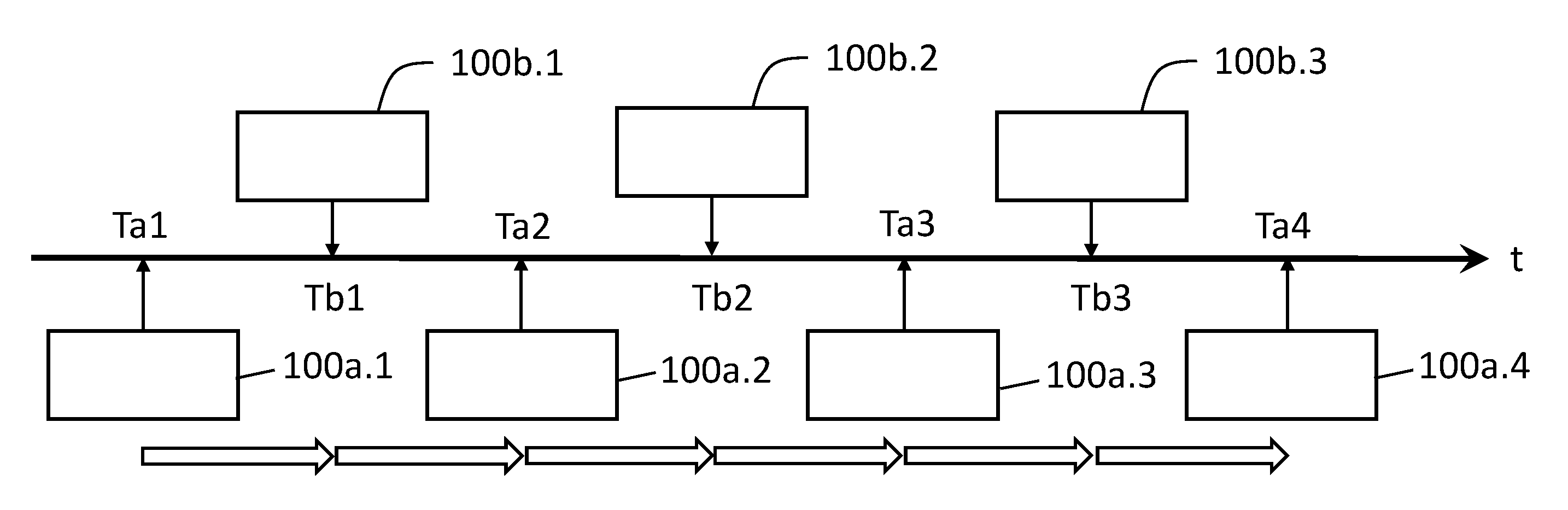
도 4는 연속 밀링 모드에서 정렬 정보 전달의 도면이다.
도 5는 밀링-정지-이미지 모드에서 정렬 정보 전달의 도면이다.The invention will be more fully understood with reference to the following figures:
1 is a diagram of a cross-sectional imaging technique.
Figure 2 is a diagram of two examples of cross-section images and cross-section images through 3D volume images.
3 is a diagram of a fiducial alignment process as described in the prior art.
4 is a diagram of alignment information transfer in continuous milling mode.
5 is a diagram of alignment information transfer in milling-still-image mode.
도 1은 집적 반도체 샘플의 3D 체적 이미지를 얻기 위한 단면 이미지 접근법의 개략도를 도시하고 있다. 단면 접근법에 의해, 3차원(3D) 체적 이미지 획득이 "단계 및 반복" 방식에 의해 달성된다. 먼저, 집적 반도체 샘플은 관련 기술 분야에 알려진 방법에 의해 후속 단면 이미지 접근법을 위해 준비된다. 본 개시내용 전체에 걸쳐, "단면 이미지"와 "슬라이스"는 동의어로서 사용될 것이다. 홈이 집적 반도체의 상부면에 밀링되어 상부면에 대략 수직인 단면이 접근 가능하게 하거나, 또는 블록 형상의 집적 반도체 샘플(10)이 절결되어 집적 반도체 웨이퍼로부터 제거된다. 이 프로세스 단계는 때때로 "리프트 아웃(lift-out)"이라 칭한다. 일 단계에서, 재료의 얇은 표면층 또는 "슬라이스"가 제거된다. 단순화를 위해, 이러한 블록 형상의 집적 반도체 샘플(10)에 대한 설명이 개시되어 있지만, 본 발명은 블록 형상 샘플(10)에 한정되지 않는다. 이 재료의 슬라이스는, 집속 이온 빔 밀링 또는 스침각(glancing angle)에서, 그러나 때때로 집속 이온 빔(FIB)(50)에 의한 수직 입사에 더 근접하게 연마의 사용을 포함하여, 관련 기술 분야에 알려진 여러 방법으로 제거될 수도 있다. 예를 들어, 집속 이온 빔(51)은 단면(52)을 형성하기 위해 방향(x)을 따라 스캐닝된다. 그 결과, 새로운 단면 표면(11)이 이미징을 위해 접근 가능하다. 후속 단계에서, 새롭게 접근 가능한 단면 표면층(11)은 주사 전자 현미경(SEM) 또는 FIB(도시되어 있지 않음)와 같은, 하전 입자 빔(CPB)에 의해 래스터 스캐닝된다. 이미징 시스템 광축은 z-방향에 평행하도록 배열되거나, 또는 z-방향에 대해 소정 각도로 경사질 수 있다. CPB 시스템은 2 nm 미만의 고해상도로 샘플의 작은 영역을 이미징하기 위해 사용되었다. 2차 뿐만 아니라 후방 산란된 전자는 검출기(도시되어 있지 않음)에 의해 수집되어 집적 반도체 샘플의 내부의 재료 대비를 드러내고, 단면 이미지(100)에서 상이한 그레이 레벨로 가시화된다. 금속 구조는 더 밝은 측정 결과를 생성한다. 표면층 제거 및 단면 이미지 프로세스는 동일한 거리에서 표면(53, 54) 및 추가 표면을 통해 반복되고, 상이한 깊이의 샘플을 통한 2D 단면 이미지(1000)의 시퀀스가 3차원(3D) 데이터 세트를 구축하기 위해 얻어진다. 대표적인 단면 이미지(100)는 14 nm 기술에 의한 상업용 인텔(Intel) 프로세서 집적 반도체 칩의 측정에 의해 얻어진다.1 shows a schematic diagram of a cross-sectional imaging approach to obtain a 3D volumetric image of an integrated semiconductor sample. With the cross-sectional approach, three-dimensional (3D) volumetric image acquisition is achieved in a “step and iterate” manner. First, the integrated semiconductor sample is prepared for subsequent cross-sectional imaging approaches by methods known in the art. Throughout this disclosure, "cross-sectional image" and "slice" will be used synonymously. A groove is milled into the top surface of the integrated semiconductor to make a cross-section approximately perpendicular to the top surface accessible, or the block-shaped
이 방법에 의해, 적어도 제1 및 제2 단면 이미지는 새로운 단면을 이미징을 위해 접근 가능하게 하기 위해 특히 집속 이온 빔으로 집적 반도체 샘플의 단면 표면층을 후속적으로 제거하는 것, 및 특히 하전 입자 빔으로 집적 반도체 샘플의 새로운 단면을 이미징하는 것을 포함한다. 이들 2D 단면 이미지(1000)의 시퀀스로부터, 집적 반도체 구조체의 3D 이미지가 재구성될 수 있다. 단면 이미지(100)의 거리(dz)는 FIB 밀링 또는 연마 프로세스에 의해 제어될 수 있고 1 nm 내지 10 nm, 예를 들어 약 3 내지 5 nm일 수 있지만, 구체적인 용례에 따라 다른 값이 또한 가능하다.By this method, at least first and second cross-sectional images are obtained by subsequent ablation of the cross-sectional surface layer of the integrated semiconductor sample, in particular with a focused ion beam, and in particular with a charged particle beam, to make a new cross-section accessible for imaging. and imaging a new cross-section of the integrated semiconductor sample. From the sequence of these 2D
도 2는 재구성된 3D 체적 이미지 또는 N=400개의 이미지 슬라이스 또는 x-y-방향에서 얻어지고 거리(dz)만큼 z-방향으로 이격된 단면 이미지(1000)의 시퀀스로부터 얻어진 3D 데이터 세트로부터 2개의 x-z-교차 이미지의 예를 도시하고 있다. 단순화를 위해, 단지 3개의 단면 이미지(100.1, 100.2, 100.3)만이 도시되어 있다. N=400개의 이미지 슬라이스의 획득 사이의 랜덤 스테이지 또는 SEM 드리프트는 z-방향으로 연장된 금속 라인(101)에서 가시화되는 z-방향으로 인공적으로 향상된 라인 에지 거칠기, 또는 z-방향에 수직으로 배향된 금속 라인(102)의 폭의 큰 변동을 야기한다.FIG. 2 is a reconstructed 3D volumetric image or two x-z- from a 3D data set obtained from a sequence of N=400 image slices or
도 3은 종래 기술에 따른, 기점과의 정렬을 도시하고 있다. 도 3a에 도시되어 있는 바와 같이, 마커 구조 또는 기점은 교차점의 FIB 절단이 시작되기 전에 단면의 방향에 수직인 샘플의 상부에 형성된다. 마커 구조에 대해, 먼저 재료(20)가 집적 반도체 샘플의 상부면(55) 상에 퇴적된다. 이 재료에는, 평행 라인(21), 경사 라인(22)과 같은 정렬 마크가 FIB 처리에 의해 형성되어 있다. 래스터 스캐닝 라인(82)을 따른 래스터 스캐닝에 의해 단면(11)을 슬라이싱하고 이미징한 후, 각각의 단면 이미지(100)는 또한 기점 또는 정렬 마커의 단면 이미지 세그먼트를 포함한다. 도 3b에는 대표적인 단면(100)이 도시되어 있다. 중앙 마커(21)는 그 단면 이미지 세그먼트(25)를 통해 가시화되고 슬라이스 사이에서 x-방향 및 y-방향으로 측면 정렬을 수행하는 데 사용되지만; y-방향에서의 정렬은 일반적으로 덜 정확하다. 2개의 외부 마커(22)의 2개의 단면 이미지 세그먼트(27) 사이의 거리는 각각의 슬라이스 사이의 거리(dz)를 계산하는 데 사용된다.Figure 3 shows the alignment with the fiducial according to the prior art. As shown in FIG. 3A, a marker structure or fiducial is formed on top of the sample perpendicular to the direction of the cross section before FIB cutting of the intersection begins. For the marker structure,
도 4a 및 도 4b는 연속 밀링 모드에서의 정렬 정보 전달을 도시하고 있는데: 도 4a는 도면 하부에서 복수의 화살표에 의해 연속 밀링 모드를 나타내고 있다. 밀링에는 정지가 없다. 더욱이, 대응 시간 축(t)이 도시되어 있다. 복수의 시간(시간 인스턴스)에서, 단면 이미지(100)가 얻어지는데: 시간 Ta1, Ta2, Ta3 및 Ta4에서, 단면 이미지(100a.1, 100a.2, 100a.3, 100a.4)가 얻어진다. 이들 단면 이미지(100a.1, 100a.2, 100a.3, 100a.4)는 제1 단면 이미지 세트에 속하며 제1 이미징 모드에서 얻어진다. 본 예에 따르면, 단면 이미지(100a.1, 100a.2, 100a.3, 100a.4)는 비교적 큰 픽셀 크기, 예를 들어 4 nm, 6 nm, 8 nm 이상을 갖는다. 이미징된 영역은 기점을 포함하고 정렬 정보는 이들 제1 세트의 단면 이미지(100a.1, 100a.2, 100a.3, 100a.4)로부터 결정된다. 예를 들어, 기점의 위치 또는 복수의 기점(21, 22)의 위치가 단면 이미지(100a.1, 100a.2, 100a.3, 100a.4)의 각각에서 결정된다. 공지의 이미지 처리 방법은 상기 기점의 위치 또는 위치 마커를 픽셀 내에 제공한다. 제1 이미징 모드에서 픽셀 크기를 인지하는 것은 나노미터 단위로 위치를 변환/결정하는 것을 허용한다.Figures 4a and 4b show the transfer of alignment information in the continuous milling mode: Figure 4a indicates the continuous milling mode by a plurality of arrows at the bottom of the figure. Milling has no stops. Moreover, the corresponding time axis t is shown. At a plurality of times (time instances),
제시된 예에서, 단면 이미지(100b.1, 100b.2, 100b.3)는 시간(시간 인스턴스) Tb1, Tb2 및 Tb3에서 이미징된다. 이들 단면 이미지(100b.1, 100b.2, 100b.3)는 제2 단면 이미지 세트에 속하며 제1 이미징 모드와는 상이한 제2 이미징 모드에서 얻어진다. 본 예에 따르면, 단면 이미지(100b.1, 100b.2, 100b.3)는 비교적 작은 픽셀 크기, 예를 들어 2 nm, 1 nm 이하를 갖는다. 이 제2 이미징 모드에서는 기점이 이미징되지 않는다. 대신에, 제2 이미징 모드의 이미징 조건은 양호한 해상도로 관심 구조를 이미징하도록 구성된다.In the example presented, cross-sectional images 100b.1, 100b.2, 100b.3 are imaged at times (time instances) Tb1, Tb2 and Tb3. These cross-sectional images 100b.1, 100b.2, and 100b.3 belong to a second set of cross-sectional images and are obtained in a second imaging mode different from the first imaging mode. According to this example, the cross-sectional images 100b.1, 100b.2, and 100b.3 have a relatively small pixel size, for example, 2 nm, 1 nm or less. Fiducials are not imaged in this second imaging mode. Instead, the imaging conditions of the second imaging mode are configured to image the structure of interest with good resolution.
도시되어 있는 예에서, 시간 간격 ΔTa = Ta(i+1) - Tai는 모든 i에 대해 일정하다. 더욱이, 시간 간격 ΔTb = Tb(j+1) - Tbj는 모든 j에 대해 일정하다. 제1 세트의 단면 이미지(100a)는 제2 세트의 단면 이미지(100b)와 엄격하게 교대로 얻어진다.In the example shown, the time interval ΔTa = Ta(i+1) - Tai is constant for all i. Moreover, the time interval ΔTb = Tb(j+1) - Tbj is constant for all j. The cross-sectional image 100a of the first set is obtained strictly alternating with the cross-sectional image 100b of the second set.
이미 전술된 바와 같이, 위치 정보는 제1 세트의 단면 이미지(100a.1, 100a.2, 100a.3, 100a.4) 내의 위치 마커로부터 결정된다. 도 4b는 시간 Ta1, Ta2, Ta3 및 Ta4에서 결정된 위치(p)를 나타낸다. 위치(p)는 마커의 위치일 수 있지만, 이는 반드시 그러한 것은 아니다. 일 예에 따르면, p는 관심 구조 또는 관심 구조의 부분의 위치이다. 마커 구조(21, 22)와 관심 구조는 동일한 샘플 상에 존재하기 때문에, 마커의 위치를 인지하는 것은 또한 관심 구조의 위치를 결정하는 것을 허용한다. 위치(p)는 전체 공간 좌표, 예를 들어, px, py, pz로 제공될 수 있다. 위치(p)는 시간 종속적이며 시간 Ta1, Ta2, Ta3 및 Ta4에 대해 결정(측정)된다.As already mentioned above, position information is determined from position markers in the first set of cross-sectional images 100a.1, 100a.2, 100a.3 and 100a.4. Figure 4b shows the positions p determined at times Ta1, Ta2, Ta3 and Ta4. Location p may be the location of the marker, but this is not necessarily the case. According to one example, p is the location of a structure of interest or a portion of a structure of interest. Since the
이제 관심 있는 것은, 제2 세트의 단면 이미지에서 시간 Tb1, Tb2 및 Tb3에서 관심 구조의 위치(p)이다. 이 위치(p)는 이하의 근거에 따라 변하는데: 첫째, 이미징이 연속 밀링 모드에서 수행되기 때문에, 샘플의 깊이가 지속적으로 감소된다. 따라서, 슬라이싱 방향의 깊이 좌표(z-좌표)는 시간에 따라 변한다. 더욱이, 예를 들어 스테이지 위치 및/또는 이미징 컬럼의 드리프트로 인해 원치 않는 위치의 변동이 또한 존재한다. 다른 환경적 영향이 또한 발생할 수 있으며 위치(p)에 영향을 미칠 수 있다. 따라서, 본 발명에 따르면, 위치(p(Tb1), p(Tb2) 및 p(Tb3))는 시간 보간에 의해 결정되는데: 보간된 값은 원이 없는 십자표에 의해 도 4b에 나타내고, 반면 원 내부의 십자표는 위치(p)의 시간 종속 보간에 대한 이산 값을 제공하는 측정값을 나타낸다. 도 4b의 직선은 본 예에서 선형인 보간 함수이다. 따라서, 정렬 정보 또는 위치 정보(p)는 상기 위치 정보(p)의 시간 종속 보간에 의해 제1 단면 이미지 세트(100a.1, 100a.2, 100a.3, 100a.4)로부터 제2 단면 이미지 세트(100b.1, 100b.2, 100b.3)로 전달된다.Now of interest is the position (p) of the structure of interest at times Tb1, Tb2 and Tb3 in the second set of cross-sectional images. This position p varies according to the following reasons: First, since the imaging is performed in continuous milling mode, the depth of the sample is continuously reduced. Accordingly, the depth coordinate (z-coordinate) in the slicing direction changes with time. Furthermore, there are also unwanted positional fluctuations, for example due to drift of the stage position and/or imaging column. Other environmental influences may also occur and may affect location p. Thus, according to the present invention, the positions p(Tb1), p(Tb2) and p(Tb3) are determined by temporal interpolation: the interpolated values are indicated in Fig. 4b by crosses without circles, whereas the circles The crosshairs inside represent measurements that give discrete values for the time-dependent interpolation of position p. The straight line in FIG. 4B is an interpolation function that is linear in this example. Accordingly, alignment information or location information p is obtained from the first cross-sectional image set 100a.1, 100a.2, 100a.3, and 100a.4 by time-dependent interpolation of the location information p. It is delivered to sets 100b.1, 100b.2, and 100b.3.
도 5a 및 도 5b는 밀링-정지-이미지 모드에서 정렬 정보 전달을 도시하고 있다. 이하에는, 연속 밀링 모드의 정렬 전달과 밀링-정지-이미지 모드의 정렬 전달 사이의 차이만이 설명될 것이다. 밀링-정지-이미지 모드는 도 5a의 하부에 중단된 복수의 화살표에 의해 나타낸다. 밀링-정지-이미지 모드는 제1 이미징 모드와 제2 이미징 모드의 모두에서 단면 이미지를 얻을 때 밀링이 일시 중지되는 것을 특징으로 한다. 더욱이, 제1 세트의 단면 이미지를 얻는 것과 제2 세트의 대응 단면 이미지를 얻는 것 사이에는 밀링이 없다. 달리 말하면, 제1 세트의 단면 이미지와 제2 세트의 대응 단면 이미지에서 슬라이싱 방향에서 그 위치를 비교할 때 임의의 위치 마커의 변화가 없다. 위치 마커 또는 관심 위치(pz)의 깊이 위치(z-좌표)는 일정하게 유지된다. 따라서, 제1 세트의 단면 이미지에서 위치 정보(pz)를 결정하면, 이 위치(pz)는 제2 세트의 단면 이미지로 동일하게 전달될 수 있다(여전히, 양 단면 이미지 세트에서 상이한 픽셀 크기는 전달을 계산하기 위해 고려되어야 함)5A and 5B show alignment information delivery in milling-still-image mode. In the following, only the difference between alignment transfer in the continuous milling mode and alignment transfer in the milling-still-image mode will be explained. The milling-still-image mode is indicated by a plurality of arrows interrupted at the bottom of FIG. 5A. The milling-stop-image mode is characterized in that milling is paused when cross-sectional images are obtained in both the first imaging mode and the second imaging mode. Moreover, there is no milling between obtaining the first set of cross-sectional images and obtaining the second set of corresponding cross-sectional images. In other words, there is no change of any position marker when comparing its position in the slicing direction in the cross-sectional image of the first set and the corresponding cross-sectional image of the second set. The depth position (z-coordinate) of the position marker or the position of interest (pz) is kept constant. Thus, once we determine the positional information pz in the first set of cross-section images, this position pz can be equally transferred to the second set of cross-section images (still different pixel sizes in both sets of cross-section images). must be taken into account to calculate
대응 단면 이미지 사이에 깊이 방향의 변화는 없지만, 다른 공간 좌표와 관련하여 여전히 평활하고 서서히 변화하는 위치(p)의 변화, 즉 측면 위치(px 및/또는 py)가 존재하는데: 여기서, 스테이지 및/또는 이미징 컬럼의 드리프트가 여전히 발생할 수 있다. 다시 한 번, 이들 드리프트 또는 드리프트들은 시간에 종속하는 평활 함수에 의해, 예를 들어 시간의 선형 함수에 의해 근사될 수 있다. 따라서, 연속 밀링 모드와 유사하게, 제2 세트의 단면 이미지에서 측면 위치(plateral)는 제1 세트의 단면 이미지에서 측정된 데이터 지점으로부터 계산될 수 있다. 도 5b는 측면 위치 편차를 예시하기 위한 보간 함수의 예를 도시하고 있는데: 제2 단면 이미지 세트에서 관심 구조의 시간 Tb, Tb2 및 Tb3에서 측면 위치(plateral)는 시간 종속 보간에 의해 결정될 수 있다.There is no change in the depth direction between the corresponding cross-sectional images, but there is still a smooth and slowly changing change in position (p) with respect to the other spatial coordinates, namely the lateral position (px and/or py): where the stage and/or Alternatively, drift of the imaging column may still occur. Once again, these drift or drifts can be approximated by a time-dependent smoothing function, for example by a linear function of time. Thus, similar to the continuous milling mode, the lateral position p lateral in the second set of cross-sectional images can be calculated from the measured data points in the first set of cross-sectional images. 5b shows an example of an interpolation function for illustrating the lateral position deviation: the lateral position (p lateral ) at times Tb, Tb2 and Tb3 of the structure of interest in the second cross-sectional image set can be determined by time dependent interpolation. .
본 예에서, 선형 보간이 개시되었지만; 원리적으로 고차 보간이 또한 가능하다.In this example, linear interpolation is disclosed; In principle higher order interpolation is also possible.
Claims (23)
시간 Tai에서 촬영되는 제1 단면 이미지 세트를 제1 이미징 모드에서 얻는 단계;
시간 Tai와는 상이한 시간 Tbj에서 촬영되는 제2 단면 이미지 세트를 제2 이미징 모드에서 얻는 단계로서;
여기서 제1 및 제2 단면 이미지 세트를 얻는 단계는 후속적으로 특히 집속 이온 빔을 사용하여 샘플의 단면 표면층을 제거하여 이미징을 위해 접근 가능한 새로운 단면을 만드는 단계, 및 특히 하전 입자 빔으로 제1 이미징 모드 또는 제2 이미징 모드에서 샘플의 새로운 단면을 이미징하는 단계를 포함하고,
제1 및 제2 단면 이미지 세트를 얻는 동안 제1 이미징 모드와 제2 이미징 모드 사이에서 전환이 수행되는, 제1 및 제2 단면 이미지 세트를 얻는 단계;
제1 세트의 단면 이미지에 포함된 정렬 정보를 결정하는 단계; 및
제1 세트의 단면 이미지로부터의 정렬 정보를 제2 세트의 단면 이미지로 전달하는 단계를 포함하고,
정렬 정보를 전달하는 단계는 정렬 정보의 시간 종속 보간을 포함하는, 방법.A method for transferring alignment information from a first image set to a second image set in 3D tomography, with the following steps:
obtaining a first set of cross-sectional images taken at time Tai in a first imaging mode;
obtaining in a second imaging mode a second set of cross-sectional images taken at a time Tbj different from time Tai;
Obtaining first and second sets of cross-sectional images herein includes subsequently removing a cross-sectional surface layer of the sample, in particular with a focused ion beam, to make a new cross-section accessible for imaging, and in particular with a first imaging with a charged particle beam. imaging a new cross-section of the sample in either mode or a second imaging mode;
obtaining first and second cross-sectional image sets, wherein switching is performed between the first imaging mode and the second imaging mode while obtaining the first and second cross-sectional image sets;
determining alignment information included in the first set of cross-sectional images; and
passing alignment information from a first set of cross-sectional images to a second set of cross-sectional images;
The method of claim 1 , wherein passing alignment information includes time-dependent interpolation of the alignment information.
얻어진 단면 이미지의 이미지 정합을 수행하고 3D 데이터 세트를 얻는 단계를 더 포함하는, 방법.19. The method of any one of claims 1 to 18, wherein the following steps:
and performing image registration of the obtained cross-sectional images and obtaining a 3D data set.
집속 이온 빔 디바이스;
전자 또는 이온으로 동작하고 샘플의 새로운 단면의 이미징을 위해 구성된 하전 입자 동작 디바이스를 포함하고,
집속 이온 빔과 전자/이온 빔은 서로 소정 각도로 배열되고 동작되며, 집속 이온 빔의 빔축과 전자/이온 빔의 빔축은 서로 교차하는, 검사 디바이스.According to claim 21,
a focused ion beam device;
a charged particle motion device operated with electrons or ions and configured for imaging of a new cross-section of a sample;
The inspection device, wherein the focused ion beam and the electron/ion beam are arranged and operated at a predetermined angle from each other, and a beam axis of the focused ion beam and a beam axis of the electron/ion beam cross each other.
집속 이온 빔과 전자/이온 빔은 서로 약 90°의 각도를 형성하는, 검사 디바이스.According to claim 21 or 22,
wherein the focused ion beam and the electron/ion beam form an angle of about 90° to each other.
Applications Claiming Priority (3)
| Application Number | Priority Date | Filing Date | Title |
|---|---|---|---|
| US202063109447P | 2020-11-04 | 2020-11-04 | |
| US63/109,447 | 2020-11-04 | ||
| PCT/EP2021/025402 WO2022096144A1 (en) | 2020-11-04 | 2021-10-14 | Transferring alignment information in 3d tomography from a first set of images to a second set of images |
Publications (1)
| Publication Number | Publication Date |
|---|---|
| KR20230074807A true KR20230074807A (en) | 2023-05-31 |
Family
ID=78134912
Family Applications (1)
| Application Number | Title | Priority Date | Filing Date |
|---|---|---|---|
| KR1020237014482A Ceased KR20230074807A (en) | 2020-11-04 | 2021-10-14 | Passing the alignment information of the 3D tomography from the first set of images to the second set of images |
Country Status (4)
| Country | Link |
|---|---|
| US (1) | US20230267627A1 (en) |
| KR (1) | KR20230074807A (en) |
| CN (1) | CN116438571A (en) |
| WO (1) | WO2022096144A1 (en) |
Families Citing this family (1)
| Publication number | Priority date | Publication date | Assignee | Title |
|---|---|---|---|---|
| US20240281952A1 (en) | 2023-02-22 | 2024-08-22 | Carl Zeiss Smt Gmbh | 3d volume inspection method and method of configuring of a 3d volume inspection method |
Family Cites Families (3)
| Publication number | Priority date | Publication date | Assignee | Title |
|---|---|---|---|---|
| US7312448B2 (en) * | 2005-04-06 | 2007-12-25 | Carl Zeiss Nts Gmbh | Method and apparatus for quantitative three-dimensional reconstruction in scanning electron microscopy |
| EP3528276A3 (en) | 2011-05-13 | 2019-09-04 | Fibics Incorporated | Microscopy imaging method |
| MX2014003968A (en) * | 2011-10-14 | 2014-08-27 | Ingrain Inc | Dual image method and system for generating a multi-dimensional image of a sample. |
-
2021
- 2021-10-14 KR KR1020237014482A patent/KR20230074807A/en not_active Ceased
- 2021-10-14 CN CN202180073856.XA patent/CN116438571A/en active Pending
- 2021-10-14 WO PCT/EP2021/025402 patent/WO2022096144A1/en not_active Ceased
-
2023
- 2023-05-01 US US18/310,163 patent/US20230267627A1/en active Pending
Also Published As
| Publication number | Publication date |
|---|---|
| CN116438571A (en) | 2023-07-14 |
| US20230267627A1 (en) | 2023-08-24 |
| WO2022096144A1 (en) | 2022-05-12 |
Similar Documents
| Publication | Publication Date | Title |
|---|---|---|
| JP7546001B2 (en) | Cross-sectional imaging with improved 3D volumetric image reconstruction accuracy - Patents.com | |
| KR102828411B1 (en) | Method for cross-sectional imaging of the inspection volume of a wafer | |
| TWI820526B (en) | Method of wafer inspection | |
| TW202307900A (en) | Segmentation or cross sections of high aspect ratio structures | |
| US12283504B2 (en) | Contact area size determination between 3D structures in an integrated semiconductor sample | |
| Winiarski et al. | Correction of artefacts associated with large area EBSD | |
| KR20240121855A (en) | 3D volume inspection of semiconductor wafers with increased accuracy | |
| US20250022680A1 (en) | 3d volume inspection of semiconductor wafers with increased throughput and accuracy | |
| KR20240072250A (en) | Workflow for aligning semiconductor samples and/or measuring misalignment of semiconductor samples in a FIB-SEM or FIB-HIM device | |
| US20230267627A1 (en) | Transferring alignment information in 3d tomography from a first set of images to a second set of images | |
| US20250259413A1 (en) | Method and apparatus for segmentation of semiconductor inspection images | |
| US20250362253A1 (en) | 3d volume inspection method and method of configuring of a 3d volume inspection method | |
| US20260074145A1 (en) | Height measurements using focus line | |
| WO2025180880A1 (en) | Reference image for distortion correction | |
| WO2025242376A1 (en) | Semiconductor sample with reduced preparation time |
Legal Events
| Date | Code | Title | Description |
|---|---|---|---|
| A201 | Request for examination | ||
| P11-X000 | Amendment of application requested |
St.27 status event code: A-2-2-P10-P11-nap-X000 |
|
| P13-X000 | Application amended |
St.27 status event code: A-2-2-P10-P13-nap-X000 |
|
| PA0105 | International application |
St.27 status event code: A-0-1-A10-A15-nap-PA0105 |
|
| PA0201 | Request for examination |
St.27 status event code: A-1-2-D10-D11-exm-PA0201 |
|
| PG1501 | Laying open of application |
St.27 status event code: A-1-1-Q10-Q12-nap-PG1501 |
|
| D13-X000 | Search requested |
St.27 status event code: A-1-2-D10-D13-srh-X000 |
|
| E902 | Notification of reason for refusal | ||
| PE0902 | Notice of grounds for rejection |
St.27 status event code: A-1-2-D10-D21-exm-PE0902 |
|
| T11-X000 | Administrative time limit extension requested |
St.27 status event code: U-3-3-T10-T11-oth-X000 |
|
| T11-X000 | Administrative time limit extension requested |
St.27 status event code: U-3-3-T10-T11-oth-X000 |
|
| E13-X000 | Pre-grant limitation requested |
St.27 status event code: A-2-3-E10-E13-lim-X000 |
|
| P11-X000 | Amendment of application requested |
St.27 status event code: A-2-2-P10-P11-nap-X000 |
|
| B15 | Application refused following examination |
Free format text: ST27 STATUS EVENT CODE: N-2-6-B10-B15-EXM-PE0601 (AS PROVIDED BY THE NATIONAL OFFICE) |
|
| PE0601 | Decision on rejection of patent |
St.27 status event code: N-2-6-B10-B15-exm-PE0601 |
|
| P22-X000 | Classification modified |
St.27 status event code: A-2-2-P10-P22-nap-X000 |
|
| T11 | Administrative time limit extension requested |
Free format text: ST27 STATUS EVENT CODE: U-3-3-T10-T11-OTH-X000 (AS PROVIDED BY THE NATIONAL OFFICE) |
|
| T11-X000 | Administrative time limit extension requested |
St.27 status event code: U-3-3-T10-T11-oth-X000 |
|
| T13 | Administrative time limit extension granted |
Free format text: ST27 STATUS EVENT CODE: U-3-3-T10-T13-OTH-X000 (AS PROVIDED BY THE NATIONAL OFFICE) |
|
| T13-X000 | Administrative time limit extension granted |
St.27 status event code: U-3-3-T10-T13-oth-X000 |
|
| T11 | Administrative time limit extension requested |
Free format text: ST27 STATUS EVENT CODE: U-3-3-T10-T11-OTH-X000 (AS PROVIDED BY THE NATIONAL OFFICE) |
|
| T11-X000 | Administrative time limit extension requested |
St.27 status event code: U-3-3-T10-T11-oth-X000 |
|
| T13 | Administrative time limit extension granted |
Free format text: ST27 STATUS EVENT CODE: U-3-3-T10-T13-OTH-X000 (AS PROVIDED BY THE NATIONAL OFFICE) |
|
| T13-X000 | Administrative time limit extension granted |
St.27 status event code: U-3-3-T10-T13-oth-X000 |
|
| R17 | Change to representative recorded |
Free format text: ST27 STATUS EVENT CODE: A-3-3-R10-R17-OTH-X000 (AS PROVIDED BY THE NATIONAL OFFICE) |
|
| R17-X000 | Change to representative recorded |
St.27 status event code: A-3-3-R10-R17-oth-X000 |
|
| P11 | Amendment of application requested |
Free format text: ST27 STATUS EVENT CODE: A-2-2-P10-P11-NAP-X000 (AS PROVIDED BY THE NATIONAL OFFICE) |
|
| P11-X000 | Amendment of application requested |
St.27 status event code: A-2-2-P10-P11-nap-X000 |