KR20100108214A - Light-emitting device and method for manufacturing the same - Google Patents
Light-emitting device and method for manufacturing the same Download PDFInfo
- Publication number
- KR20100108214A KR20100108214A KR1020100022622A KR20100022622A KR20100108214A KR 20100108214 A KR20100108214 A KR 20100108214A KR 1020100022622 A KR1020100022622 A KR 1020100022622A KR 20100022622 A KR20100022622 A KR 20100022622A KR 20100108214 A KR20100108214 A KR 20100108214A
- Authority
- KR
- South Korea
- Prior art keywords
- light
- layer
- electrode
- organic material
- oxide
- Prior art date
- Legal status (The legal status is an assumption and is not a legal conclusion. Google has not performed a legal analysis and makes no representation as to the accuracy of the status listed.)
- Granted
Links
Images


Classifications
-
- H—ELECTRICITY
- H10—SEMICONDUCTOR DEVICES; ELECTRIC SOLID-STATE DEVICES NOT OTHERWISE PROVIDED FOR
- H10K—ORGANIC ELECTRIC SOLID-STATE DEVICES
- H10K71/00—Manufacture or treatment specially adapted for the organic devices covered by this subclass
- H10K71/80—Manufacture or treatment specially adapted for the organic devices covered by this subclass using temporary substrates
-
- H—ELECTRICITY
- H10—SEMICONDUCTOR DEVICES; ELECTRIC SOLID-STATE DEVICES NOT OTHERWISE PROVIDED FOR
- H10K—ORGANIC ELECTRIC SOLID-STATE DEVICES
- H10K59/00—Integrated devices, or assemblies of multiple devices, comprising at least one organic light-emitting element covered by group H10K50/00
- H10K59/10—OLED displays
- H10K59/12—Active-matrix OLED [AMOLED] displays
- H10K59/1201—Manufacture or treatment
-
- H—ELECTRICITY
- H10—SEMICONDUCTOR DEVICES; ELECTRIC SOLID-STATE DEVICES NOT OTHERWISE PROVIDED FOR
- H10K—ORGANIC ELECTRIC SOLID-STATE DEVICES
- H10K59/00—Integrated devices, or assemblies of multiple devices, comprising at least one organic light-emitting element covered by group H10K50/00
- H10K59/10—OLED displays
- H10K59/12—Active-matrix OLED [AMOLED] displays
- H10K59/122—Pixel-defining structures or layers, e.g. banks
-
- H—ELECTRICITY
- H10—SEMICONDUCTOR DEVICES; ELECTRIC SOLID-STATE DEVICES NOT OTHERWISE PROVIDED FOR
- H10K—ORGANIC ELECTRIC SOLID-STATE DEVICES
- H10K59/00—Integrated devices, or assemblies of multiple devices, comprising at least one organic light-emitting element covered by group H10K50/00
- H10K59/30—Devices specially adapted for multicolour light emission
- H10K59/35—Devices specially adapted for multicolour light emission comprising red-green-blue [RGB] subpixels
- H10K59/353—Devices specially adapted for multicolour light emission comprising red-green-blue [RGB] subpixels characterised by the geometrical arrangement of the RGB subpixels
-
- H—ELECTRICITY
- H10—SEMICONDUCTOR DEVICES; ELECTRIC SOLID-STATE DEVICES NOT OTHERWISE PROVIDED FOR
- H10K—ORGANIC ELECTRIC SOLID-STATE DEVICES
- H10K71/00—Manufacture or treatment specially adapted for the organic devices covered by this subclass
-
- H—ELECTRICITY
- H10—SEMICONDUCTOR DEVICES; ELECTRIC SOLID-STATE DEVICES NOT OTHERWISE PROVIDED FOR
- H10K—ORGANIC ELECTRIC SOLID-STATE DEVICES
- H10K71/00—Manufacture or treatment specially adapted for the organic devices covered by this subclass
- H10K71/40—Thermal treatment, e.g. annealing in the presence of a solvent vapour
-
- H—ELECTRICITY
- H10—SEMICONDUCTOR DEVICES; ELECTRIC SOLID-STATE DEVICES NOT OTHERWISE PROVIDED FOR
- H10K—ORGANIC ELECTRIC SOLID-STATE DEVICES
- H10K71/00—Manufacture or treatment specially adapted for the organic devices covered by this subclass
- H10K71/60—Forming conductive regions or layers, e.g. electrodes
Landscapes
- Engineering & Computer Science (AREA)
- Manufacturing & Machinery (AREA)
- Microelectronics & Electronic Packaging (AREA)
- Electroluminescent Light Sources (AREA)
- Devices For Indicating Variable Information By Combining Individual Elements (AREA)
- Telephone Set Structure (AREA)
- Signal Processing (AREA)
- Computer Networks & Wireless Communication (AREA)
Abstract
반도체 회로 소자 및 발광 소자와 기판을 분리층에 의하여 분리할 때에, 전극과 유기층의 계면에서 벗겨지는 것을 억제하는 것을 과제로 한다. 제 1 기판 위에, 분리층을 형성하고, 상기 분리층 위에, 반도체 회로 소자층 및 제 1 전극을 형성하고, 제 1 전극의 단부와 겹치는 격벽을 형성하고, 제 1 전극 위에 유기물층을 형성하고, 유기물층은 같은 색깔을 발광하는 유기물층끼리 이웃하여 일렬로 배치되고, 그 영역이 연장되어 있는 방향을 제 1 방향으로 하고, 유기물층 위에, 격벽에 접하고, 격벽과 밀착성이 좋은 재료를 사용하여 형성된 제 2 전극을 형성하고, 분리층을 통하고, 기판으로부터, 반도체 회로 소자층, 제 1 전극, 격벽, 유기물층, 제 2 전극을 포함하는 적층 구조를 분리하는 공정에 있어서, 기판으로부터 적층 구조를 분리하는 방향은, 제 1 방향과 수직인 제 2 방향인 발광 장치의 제작 방법에 관한 것이다.When separating a semiconductor circuit element, a light emitting element, and a board | substrate with a separating layer, it is a subject to suppress that peeling at the interface of an electrode and an organic layer. A separation layer is formed on the first substrate, a semiconductor circuit element layer and a first electrode are formed on the separation layer, a partition wall overlapping with an end of the first electrode is formed, an organic material layer is formed on the first electrode, and an organic material layer. The second electrode formed by using organic materials emitting light of the same color are arranged in a line adjacent to each other, and the direction in which the region extends is the first direction, and the organic material layer is in contact with the partition wall and made of a material having good adhesion to the partition wall. In the step of forming and separating a laminated structure including a semiconductor circuit element layer, a first electrode, a partition, an organic material layer, and a second electrode from a substrate via a separation layer, the direction of separating the laminated structure from the substrate is A manufacturing method of a light emitting device in a second direction perpendicular to the first direction.
Description
본 발명은 발광 장치 및 그 제작 방법에 관한 것이다.The present invention relates to a light emitting device and a manufacturing method thereof.
발광 소자를 갖는 발광 장치를 제작할 때에는, 유리 기판 등의 기판 위에 반도체 프로세스를 사용하여 발광 소자를 구동하기 위한 반도체 회로를 형성하고, 반도체 회로 위에 절연막(평탄화막)을 형성하고, 그 위에 발광 소자를 형성한다.When fabricating a light emitting device having a light emitting element, a semiconductor circuit for driving the light emitting element is formed on a substrate such as a glass substrate using a semiconductor process, an insulating film (flattening film) is formed on the semiconductor circuit, and the light emitting element is formed thereon. Form.
또한, 유리 기판 등의 기판 위에 분리층을 형성하고, 분리층 위에 발광 소자를 구동하기 위한 반도체 회로 소자를 형성하고, 반도체 회로 소자 위에 절연막(평탄화막)을 형성하고, 그 위에 발광 소자를 형성하고, 분리층에 의하여 기판과 반도체 회로 소자를 분리하고, 반도체 회로 소자 및 발광 소자를 가요성 기판 위에 전치하고, 가요성 발광 장치를 제작하는 방법이 있다(특허 문헌 1 참조).Further, a separation layer is formed on a substrate such as a glass substrate, a semiconductor circuit element for driving a light emitting element is formed on the separation layer, an insulating film (flattening film) is formed on the semiconductor circuit element, and a light emitting element is formed thereon. There is a method of separating the substrate and the semiconductor circuit element by the separation layer, displacing the semiconductor circuit element and the light emitting element on the flexible substrate, and manufacturing the flexible light emitting device (see Patent Document 1).
특허 문헌 1에서는, 양극, 유기 발광층, 음극을 포함하는 발광 소자 위에, 층간 절연막을 형성하고, 또한, 층간 절연막과 지지체를 접착층으로 접합한다. 이어서 분리층인 제 1 재료층 및 제 2 재료층에 의하여, 반도체 회로 소자 및 발광 소자와, 기판을 분리한다. 분리된 반도체 회로 소자 및 발광 소자는, 접착층에 의하여 필름 기판에 접합된다.In patent document 1, an interlayer insulation film is formed on the light emitting element containing an anode, an organic light emitting layer, and a cathode, and an interlayer insulation film and a support body are bonded by an adhesive layer. Subsequently, a semiconductor circuit element, a light emitting element, and a board | substrate are isolate | separated by the 1st material layer and the 2nd material layer which are separation layers. The separated semiconductor circuit element and the light emitting element are bonded to the film substrate by the adhesive layer.
여기서, 유기층과 그 위에 형성되는 음극 또는 양극인 전극과의 밀착성이 약한 경우, 반도체 회로 소자 및 발광 소자와 기판을 분리층에 의하여 분리할 때에, 전극과 유기층의 계면에서 벗겨질 우려가 있다.Here, when the adhesion between the organic layer and the electrode which is a cathode or an anode formed thereon is weak, there is a fear that the semiconductor circuit element, the light emitting element and the substrate are separated at the interface between the electrode and the organic layer when the substrate is separated by a separation layer.
따라서, 본 발명의 일 형태에서는, 반도체 회로 소자 및 발광 소자와 기판을 분리층에 의하여 분리할 때에, 전극과 유기층의 계면에서 벗겨지는 것을 억제하는 것을 과제로 한다.Therefore, in one embodiment of the present invention, when the semiconductor circuit element, the light emitting element, and the substrate are separated by the separation layer, it is a problem to suppress peeling at the interface between the electrode and the organic layer.
복수의 화소를 갖는 발광 장치에 있어서, 발광 소자를 화소 각각에 제작할 때에, 유기층 위에 형성되는 음극 또는 양극인 전극, 및 격벽이 접촉하는 영역을 각각의 화소 주변에 배치한다. 전극과 밀착성이 좋은 격벽을 형성함으로써, 반도체 회로 소자 및 발광 소자와, 기판을 분리할 때에, 유기층과 전극이 벗겨지지 않고, 반도체 회로 소자 및 발광 소자와, 기판을 분리할 수 있다.In a light emitting device having a plurality of pixels, when a light emitting element is fabricated in each of the pixels, an electrode, which is a cathode or an anode formed on an organic layer, and a region in which the partition walls contact each other are disposed around each pixel. By forming a partition with good adhesion with the electrode, the organic layer and the electrode do not peel off when the semiconductor circuit element, the light emitting element, and the substrate are separated, and the semiconductor circuit element, the light emitting element, and the substrate can be separated.
제 1 기판 위에, 분리층을 형성하고, 상기 분리층 위에, 반도체 회로 소자층을 형성하고, 상기 반도체 회로 소자층 위에, 상기 반도체 회로 소자층과 전기적으로 접속되는 복수의 제 1 전극을 형성한다. 상기 반도체 회로 소자층 위에, 상기 복수의 제 1 전극의 각각의 단부와 겹치는 격벽을 형성하고, 상기 복수의 제 1 전극의 각각 위에, 적색을 발광하는 유기물층, 녹색을 발광하는 유기물층, 청색을 발광하는 유기물층의 어느 것을 형성한다. 상기 적색을 발광하는 유기물층, 녹색을 발광하는 유기물층, 청색을 발광하는 유기물층의 각각은, 같은 색을 발광하는 유기물층끼리 이웃하여 일렬로 배열되고, 상기 적색을 발광하는 유기물층이 이웃하여 일렬로 배열되는 제 1 영역, 상기 녹색을 발광하는 유기물층이 이웃하여 일렬로 배열되는 제 2 영역, 상기 청색을 발광하는 유기물층이 이웃하여 일렬로 배열되는 제 3 영역에 있어서, 상기 제 1 영역, 제 2 영역, 제 3 영역 각각이 연장되어 있는 방향을 제 1 방향으로 한다. 또한, 상기 격벽은, 상기 제 1 영역과 제 2 영역 사이, 상기 제 2 영역과 제 3 영역 사이, 상기 제 3 영역과 제 1 영역 사이에 존재하고, 또한 상기 격벽은, 상기 제 1 방향으로 연장된다. 상기 유기물층 위에, 상기 격벽에 접하고, 상기 격벽과 밀착성이 좋은 재료를 사용하여 형성된 제 2 전극을 형성하고, 상기 분리층을 통하여, 상기 기판으로부터 상기 반도체 회로 소자층, 상기 제 1 전극, 상기 격벽, 상기 유기물층, 상기 제 2 전극을 포함하는 적층 구조를 분리하는 공정에 있어서, 상기 기판으로부터, 상기 반도체 회로 소자층, 상기 제 1 전극, 상기 격벽, 상기 유기물층, 상기 제 2 전극을 포함하는 적층 구조를 분리하는 방향은, 제 1 방향과 수직인 제 2 방향인 것을 특징으로 하는 발광 장치의 제작 방법에 관한 것이다.A separation layer is formed on the first substrate, a semiconductor circuit element layer is formed on the separation layer, and a plurality of first electrodes electrically connected to the semiconductor circuit element layer are formed on the semiconductor circuit element layer. On the semiconductor circuit element layer, a partition wall overlapping each end of the plurality of first electrodes is formed, and on each of the plurality of first electrodes, an organic material layer emitting red light, an organic material layer emitting green light, and a light emitting blue light One of the organic material layers is formed. Each of the organic material layer emitting red light, the organic material layer emitting green light, and the organic material layer emitting blue light are arranged in a row next to each other, and the organic material layers emitting red light are arranged in a row next to each other. In a first region, a second region in which the organic light emitting layers emitting green are arranged in a line adjacent to each other, and a third region in which the organic light emitting layers emitting blue light are arranged in a line adjacent to each other, the first region, the second region, and the third region. The direction in which each of the regions extends is the first direction. The partition wall is present between the first area and the second area, between the second area and the third area, between the third area and the first area, and the partition wall extends in the first direction. do. A second electrode is formed on the organic layer, the second electrode formed by using a material in contact with the partition wall and having good adhesion to the partition wall. The semiconductor circuit element layer, the first electrode, the partition wall, In the step of separating the laminated structure including the organic layer and the second electrode, a laminated structure comprising the semiconductor circuit element layer, the first electrode, the partition, the organic layer, and the second electrode from the substrate. The separating direction relates to a manufacturing method of a light emitting device, characterized in that the second direction is perpendicular to the first direction.
상기 격벽은, 무기재료 또는 유기재료를 사용하여 형성되고, 상기 무기재료 는, 산화실리콘, 질화실리콘, 질소를 포함하는 산화실리콘, 산소를 포함하는 질화실리콘, 다이아몬드 라이크 카본의 어느 하나, 또는 2개 이상이고, 상기 유기재료는, 폴리이미드, 아크릴, 폴리아미드, 폴리이미드아미드, 레지스트 또는 벤조시클로부텐, 실록산 중의 어느 하나, 또는 2개 이상이다.The partition wall is formed using an inorganic material or an organic material, and the inorganic material is any one or two of silicon oxide, silicon nitride, silicon oxide containing nitrogen, silicon nitride containing oxygen, and diamond-like carbon. As mentioned above, the said organic material is a polyimide, an acryl, a polyamide, a polyimide amide, a resist, benzocyclobutene, siloxane, any one, or two or more.
상기 제 2 전극은, 투광성을 갖는 양극, 투광성을 갖는 음극, 차광성을 갖는 음극, 차광성을 갖는 양극 중의 어느 하나이다.The second electrode is any one of a light-transmitting anode, a light-transmitting cathode, a light-shielding cathode, and a light-shielding anode.
상기 투광성을 갖는 양극의 재료는, 산화인듐, 산화인듐-산화주석합금, 실리콘 또는 산화실리콘을 함유한 산화인듐-산화주석, 산화텅스텐 및 산화아연을 함유한 산화인듐, 산화인듐산화아연합금, 산화아연, 갈륨(Ga)을 첨가한 산화아연 중의 어느 것이다.The light-transmitting positive electrode material includes indium oxide, indium oxide-tin oxide alloy, indium oxide-tin oxide containing silicon or silicon oxide, indium oxide containing tungsten oxide and zinc oxide, indium zinc oxide alloy, and oxidation Zinc oxide which added zinc and gallium (Ga) is either.
상기 투광성을 갖는 음극 재료는, 일 함수가 작은 재료의 극박막, 또는, 상기 일 함수가 작은 재료의 극박막과 투광성을 갖는 도전막의 적층이다.The light-transmitting negative electrode material is a laminate of an ultra-thin film of a material having a small work function or an ultra-thin film of a material having a small work function and a conductive film having a light-transmitting property.
상기 차광성을 갖는 음극 재료는, 일 함수가 작은 금속, 일 함수가 작은 합금, 일 함수가 작은 전기 도전성 화합물, 및 이들의 혼합물 중의 어느 것이고, 상기 일 함수가 작은 금속은, 리튬(Li), 세슘(Cs), 마그네슘(Mg), 칼슘(Ca), 스트론튬(Sr), 유로퓸(Eu), 이테르븀(Yb) 중의 어느 것이다.The light-shielding negative electrode material is any one of a metal having a low work function, an alloy having a low work function, an electrically conductive compound having a low work function, and a mixture thereof. The metal having a low work function is lithium (Li), Cesium (Cs), magnesium (Mg), calcium (Ca), strontium (Sr), europium (Eu) and ytterbium (Yb).
상기 차광성을 갖는 양극의 재료는, 일 함수가 큰 금속, 일 함수가 큰 합금, 일 함수가 큰 도전성 화합물, 및 이들의 혼합물 중의 어느 것이고, 상기 일 함수가 큰 금속은, 금(Au), 백금(Pt), 니켈(Ni), 텅스텐(W), 크롬(Cr), 몰리브덴(Mo), 철(Fe), 코발트(Co), 구리(Cu), 팔라듐(Pd) 중의 어느 것이다.
The material of the positive electrode having light shielding may be any one of a metal having a large work function, an alloy having a large work function, a conductive compound having a large work function, and a mixture thereof. Any of platinum (Pt), nickel (Ni), tungsten (W), chromium (Cr), molybdenum (Mo), iron (Fe), cobalt (Co), copper (Cu), and palladium (Pd).
본 발명의 일 형태는, 반도체 회로 소자 및 발광 소자와 기판을 분리층에 의하여 분리할 때에, 전극과 유기 발광층의 계면에서 벗겨지는 것을 억제하는 효과를 갖는다.One embodiment of the present invention has an effect of suppressing peeling at an interface between an electrode and an organic light emitting layer when separating a semiconductor circuit element, a light emitting element, and a substrate by a separation layer.
따라서, 신뢰성이 높은, 발광 소자와 반도체 소자를 갖는 발광 장치를 제작할 수 있다.Therefore, a light emitting device having high reliability and a light emitting element and a semiconductor element can be manufactured.
도 1a 내지 도 1e는 발광 장치의 제작 방법을 도시하는 단면도.
도 2는 발광 장치의 제작 방법을 도시하는 단면도.
도 3a 및 도 3d는 발광 장치의 제작 방법을 도시하는 단면도.
도 4a 내지 도 4c는 발광 장치의 제작 방법을 도시하는 단면도.
도 5a 및 도 5b는 발광 장치의 제작 방법을 도시하는 단면도.
도 6a 및 도 6b는 발광 장치의 제작 방법을 도시하는 단면도.
도 7a 내지 도 7c는 시트형 섬유체의 상면도 및 구조체의 단면도.
도 8은 시트형 섬유체의 상면도.
도 9는 구조체의 단면도.
도 10a 내지 도 10d는 휴대 전화기의 상면도 및 단면도.
도 11a 및 도 11b는 휴대전화기의 상면도.
도 12는 휴대전화기의 단면도.
도 13은 EL패널의 상면도.
도 14a 내지 도 14d는 휴대 전화기의 상면도 및 단면도.
도 15a 및 도 15b는 휴대 전화기의 사시도.
도 16은 발광 장치의 제작 방법을 도시하는 상면도.
도 17은 발광 장치의 제작 방법을 도시하는 상면도.1A to 1E are cross-sectional views illustrating a method of manufacturing the light emitting device.
2 is a cross-sectional view illustrating a method of manufacturing a light emitting device.
3A and 3D are sectional views showing the method of manufacturing the light emitting device.
4A to 4C are cross-sectional views illustrating a method of manufacturing the light emitting device.
5A and 5B are sectional views showing the manufacturing method of the light emitting device.
6A and 6B are sectional views showing the manufacturing method of the light emitting device.
7A to 7C are top views and cross-sectional views of the structure of sheet-like fibers.
8 is a top view of the sheet-like fibrous body.
9 is a cross-sectional view of the structure.
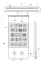
10A to 10D are top and cross-sectional views of the mobile telephone.
11A and 11B are top views of the mobile telephone.
12 is a cross-sectional view of a mobile phone.
Fig. 13 is a top view of the EL panel.
14A to 14D are top and cross-sectional views of the mobile telephone.
15A and 15B are perspective views of a mobile phone.
16 is a top view illustrating a method of manufacturing the light emitting device.
17 is a top view illustrating a method of manufacturing the light emitting device.
이하, 본 명세서에 개시되는 발명의 실시형태에 대해서, 도면을 참조하여 설명한다. 다만, 본 명세서에 개시된 발명은 많은 상이한 형태로 실시하는 것이 가능하고, 본 명세서에 개시된 발명의 취지 및 그 범위에서 일탈하지 않고 그 형태 및 상세한 내용을 다양하게 변경할 수 있다는 것은 당업자라면 용이하게 이해할 수 있다. 따라서, 실시형태의 기재 내용에 한정되어 해석되는 것이 아니다. 또한, 이하에 도시하는 도면에 있어서, 동일 부분 또는 같은 기능을 갖는 부분에는 동일의 부호를 붙이고, 그 반복 설명은 생략한다.EMBODIMENT OF THE INVENTION Hereinafter, embodiment of this invention disclosed in this specification is described with reference to drawings. However, it will be readily understood by those skilled in the art that the invention disclosed herein may be embodied in many different forms and that various modifications may be made to the form and details thereof without departing from the spirit and scope of the invention disclosed herein. have. Therefore, it is not limited to the description content of embodiment and interpreted. In addition, in the drawing shown below, the same code | symbol is attached | subjected to the same part or the part which has the same function, and the repeated description is abbreviate | omitted.
또한, 본 명세서에 개시된 발명에 있어서, 반도체 장치란, 반도체를 이용함으로써 기능하는 소자 및 장치 전반을 가리키고, 전자 회로, 표시 장치, 발광 장치 등을 포함하는 전기 장치 및 그 전기 장치를 탑재한 전자기기를 그 범주로 한다.In addition, in the invention disclosed in this specification, a semiconductor device refers to an element and a device that function by using a semiconductor, and include an electronic device including an electronic circuit, a display device, a light emitting device, and the like, and an electronic device equipped with the electric device. Makes into that category.
(실시형태 1)(Embodiment 1)
본 실시형태에서는, 발광 장치 및 그 제작 방법에 대해서, 도 1a 내지 도 1e, 도 2, 도 3a 내지 도 3d, 도 4a 내지 도 4c, 도 5a 및 도 5b, 도 6a 및 도 6b, 도 7a 내지 도 7c, 도 8, 도 9, 도 16, 도 17을 사용하여 설명한다.In this embodiment, about the light emitting device and its manufacturing method, FIGS. 1A-1E, 2, 3A-3D, 4A-4C, 5A and 5B, 6A and 6B, and 7A-, It demonstrates using FIG. 7C, FIG. 8, FIG. 9, FIG. 16, and FIG.
우선, 도 1a 내지 도 1e에 본 실시형태의 개요를 도시한다. 우선, 기판(101) 위에, 분리층(102) 및 반도체 회로 소자(103)를 제작한다(도 1a 참조).First, the outline | summary of this embodiment is shown to FIG. 1A-1E. First, the
기판(101)으로서는, 유리 기판, 석영 기판, 반도체 기판, 세라믹 기판, 금속 기판 등을 사용하면 좋다.As the
분리층(102)으로서, 플라즈마 CVD법이나 스퍼터링법 등에 의하여, 텅스텐(W), 몰리브덴(Mo), 티타늄(Ti), 탄탈(Ta), 니오븀(Nb), 니켈(Ni), 코발트(Co), 지르코늄(Zr), 아연(Zn), 루테늄(Ru), 로듐(Rh), 팔라듐(Pd), 오스뮴(Os), 이리듐(Ir), 실리콘(Si)으로부터 선택된 원소, 또는 상기 원소를 주성분으로 하는 합금 재료, 또는 화합물 재료로 이루어지는 층을, 단층 또는 적층으로 형성한다. 실리콘을 포함하는 층의 결정 구조는 비정질, 미(微)결정, 다결정 중의 어느 것이라도 좋다.As the
분리층(102)이 단층 구조인 경우, 바람직하게는, 텅스텐, 몰리브덴, 텅스텐과 몰리브덴의 혼합물, 텅스텐의 산화물, 텅스텐의 산화질화물, 텅스텐의 질화산화물, 몰리브덴의 산화물, 몰리브덴의 산화질화물, 몰리브덴의 질화산화물, 텅스텐과 몰리브덴의 혼합물의 산화물, 텅스텐과 몰리브덴의 혼합물의 산화질화물, 텅스텐과 몰리브덴의 혼합물의 질화산화물 중의 어느 것을 포함하는 층을 형성한다. 또한, 텅스텐과 몰리브덴의 혼합물이란, 예를 들어, 텅스텐과 몰리브덴의 합금에 상당한다.When the
분리층(102)이 적층 구조인 경우, 바람직하게는, 1층째로서, 텅스텐, 몰리브덴, 또는 텅스텐과 몰리브덴의 혼합물을 포함하는 층을 형성하고, 2층째로서, 텅스텐의 산화물, 몰리브덴의 산화물, 텅스텐과 몰리브덴의 혼합물의 산화물, 텅스텐의 산화질화물, 몰리브덴의 산화질화물, 또는 텅스텐과 몰리브덴의 혼합물의 산화질화물을 포함하는 층을 형성한다. 이렇게, 분리층(102)을 적층 구조로 하는 경우, 금속막과 금속산화막과의 적층 구조로 하는 것이 바람직하다. 금속 산화막의 형성 방법의 일례로서는, 스퍼터링법에 의하여 직접 금속 산화막을 형성하는 방법, 기판(101) 위에 형성한 금속막의 표면을 열처리 또는 산소 분위기하에서의 플라즈마 처리에 의하여 산화하여 금속 산화막을 형성하는 방법 등을 들 수 있다.When the
금속막으로서는, 상술한 텅스텐(W), 몰리브덴(Mo) 이외에, 티타늄(Ti), 탄탈(Ta), 니오븀(Nb), 니켈(Ni), 코발트(Co), 지르코늄(Zr), 아연(Zn), 루테늄(Ru), 로듐(Rh), 팔라듐(Pd), 오스뮴(Os), 이리듐(Ir)으로부터 선택된 원소, 또는 상기 원소를 주성분으로 하는 합금 재료, 또는 화합물 재료로 이루어지는 막을 사용할 수 있다.As the metal film, in addition to the above-mentioned tungsten (W) and molybdenum (Mo), titanium (Ti), tantalum (Ta), niobium (Nb), nickel (Ni), cobalt (Co), zirconium (Zr), and zinc (Zn) ), An element selected from ruthenium (Ru), rhodium (Rh), palladium (Pd), osmium (Os), iridium (Ir), or an alloy material containing the element as a main component, or a film made of a compound material.
또한, 분리층(102)을 형성하기 전에, 기판(101) 위에 산화실리콘막, 질화실리콘막, 질소를 포함하는 산화실리콘막, 산소를 포함하는 질화실리콘막 등의 절연막을 형성하고, 상기 절연막 위에 분리층(102)을 형성하도록 하여도 좋다. 기판(101)과 분리층(102) 사이에 이러한 절연막을 형성함으로써, 기판(101)이 포함하는 불순물이 상층에 침입해 버리는 것을 막을 수 있다. 또한, 후에 레이저를 조사하는 공정이 있을 경우, 그 공정시, 기판(101)이 에칭되어 버리는 것을 막을 수 있다. 또한, 여기서, 질소를 포함하는 산화실리콘막과, 산소를 포함하는 질화실리콘막은, 전자는 질소보다도 산소를 많이 포함하고, 후자는 산소보다도 질소를 많이 포함하는 의미로 구별해서 사용한다.Before forming the
이어서, 반도체 회로 소자(103) 위에, 반도체 회로 소자(103)와 전기적으로 접속되는 전극(104)을 형성한다. 전극(104)의 단부와 겹치도록, 격벽(105)을 형성한다(도 1b 참조). 전극(104)은, 발광 소자의 양극 또는 음극이 된다.Next, on the
발광 장치는, 양극 또는 음극의 한쪽, 또는 모두를 투광성을 갖는 도전막으로 형성할 필요가 있다. 양극 또는 음극으로서, 발광층을 포함하는 유기물층 아래에 투광성을 갖는 도전막, 및 유기물층 위에 차광성을 갖는 도전막을 형성하는 경우는, 발광 장치는 하면 사출의 발광 장치가 된다. 반대로, 양극 또는 음극으로서, 발광층을 포함하는 유기물층 아래에 차광성을 갖는 도전막, 및 유기물층 위에 투광성을 갖는 도전막을 형성하는 경우는, 발광 장치는 상면 사출의 발광 장치가 된다. 양극 및 음극의 모두를 투광성을 갖는 도전막으로 형성하는 경우는, 발광 장치는 양면 사출의 발광 장치가 된다.In the light emitting device, it is necessary to form one or both of the anode or the cathode with a light-transmitting conductive film. When the conductive film having light transmissivity and the conductive film having light shielding properties are formed below the organic material layer including the light emitting layer as the anode or the cathode, the light emitting device is a light emitting device having a lower surface emission. On the contrary, when the conductive film having light shielding property and the conductive film having light transmitting property are formed below the organic material layer including the light emitting layer as the anode or the cathode, the light emitting device is a light emitting device of top emission. When both the anode and the cathode are formed of a light-transmitting conductive film, the light emitting device is a light emitting device of double-sided injection.
투광성을 갖는 양극의 재료로서, 산화인듐(In2O3)이나 산화인듐-산화주석합금((In2O3-SnO2: Indium Tin Oxide(ITO)), 실리콘 또는 산화실리콘을 포함하는 산화인듐-산화주석, 산화텅스텐 및 산화아연을 함유한 산화인듐, 산화인듐산화아연합금(In2O3-ZnO; Indium Zinc Oxide(IZO)), 산화아연(ZnO), 또한 가시광의 투과율이나 도전율을 높이기 위해서 갈륨(Ga)을 첨가한 산화아연(ZnO: Ga), 등의 도전성 금속 산화물막을 사용할 수 있다.Indium oxide (In 2 O 3 ) or indium oxide-tin alloy ((In 2 O 3 -SnO 2 : Indium Tin Oxide (ITO)), silicon or silicon oxide containing silicon oxide as a material of the positive electrode having light Indium oxide containing zinc oxide, tungsten oxide and zinc oxide, indium zinc oxide alloy (In 2 O 3 -ZnO; Indium Zinc Oxide (IZO)), zinc oxide (ZnO), and also increase the transmittance or conductivity of visible light For this purpose, a conductive metal oxide film such as zinc oxide (ZnO: Ga) added with gallium (Ga) can be used.
이들의 재료를 스퍼터링법, 진공 증착법, 졸-겔법 등을 사용하여 형성하면 좋다.These materials may be formed using a sputtering method, a vacuum vapor deposition method, a sol-gel method or the like.
예를 들어, 산화인듐-산화아연(ZnO)은, 산화인듐에 대하여 1wt% 내지 20wt%의 산화아연을 가한 타깃을 사용하여 스퍼터링법에 의하여 형성할 수 있다. 또한, 산화텅스텐 및 산화아연을 함유한 산화인듐은, 산화인듐에 대하여 산화텅스텐을 0.5wt 내지 5wt%, 산화아연을 0.1wt 내지 1wt% 함유한 타깃을 사용하여 스퍼터링법에 의하여 형성할 수 있다.For example, indium oxide-zinc oxide (ZnO) can be formed by the sputtering method using the target which added 1 wt%-20 wt% of zinc oxide with respect to indium oxide. Indium oxide containing tungsten oxide and zinc oxide can be formed by sputtering using a target containing 0.5 wt% to 5 wt% of tungsten oxide and 0.1 wt% to 1 wt% of zinc oxide.
투광성을 갖는 음극을 형성하는 경우에는, 알루미늄 등의 일 함수가 작은 재료의 극박막을 사용하거나, 그러한 물질의 박막과 상술한 바와 같은 투광성을 갖는 도전막의 적층 구조를 사용함으로써 제작할 수 있다.In the case of forming a light-transmitting cathode, it can be produced by using an ultra-thin film of a material having a small work function such as aluminum, or by using a laminated structure of a thin film of such a material and a conductive film having light transparency as described above.
또한, 음극과 후술하는 전자 수송층 사이에, 전자 주입층을 형성함으로써, 일 함수의 크기에 상관없이, ITO, 실리콘 또는 산화실리콘을 함유한 산화인듐-산화주석 등 다양한 투광성을 갖는 도전성 재료를 음극으로서 사용할 수 있다. 이들 도전성 재료는, 스퍼터링법이나 잉크젯법, 스핀코팅법 등을 사용하여 성막할 수 있다.In addition, by forming an electron injection layer between the cathode and the electron transport layer described later, a conductive material having various light transmitting properties, such as indium oxide-tin oxide containing ITO, silicon, or silicon oxide, is used as the cathode regardless of the size of the work function. Can be used. These conductive materials can be formed into a film using a sputtering method, an inkjet method, a spin coating method, or the like.
또한, 차광성을 갖는 도전막을 음극으로서 사용하는 경우에는, 일 함수가 작은(구체적으로는 3.8eV 이하) 금속, 일 함수가 작은 합금, 일 함수가 작은 전기 전도성 화합물, 및 이들의 혼합물 등을 사용할 수 있다. 이러한 음극 재료의 구체적인 예로서는, 원소 주기율표의 제 1 족 또는 제 2 족에 속하는 원소, 즉 리튬(Li)이나 세슘(Cs) 등의 알칼리 금속, 및 마그네슘(Mg), 칼슘(Ca), 스트론튬(Sr) 등의 알칼리 토류 금속, 및 이들을 포함하는 합금(MgAg, AlLi), 유로퓸(Eu), 이테르븀(Yb) 등의 희토류 금속 및 이들을 포함하는 합금 등을 들 수 있다.In addition, in the case of using a light shielding conductive film as the cathode, a metal having a small work function (specifically 3.8 eV or less), an alloy having a small work function, an electrically conductive compound having a small work function, a mixture thereof, or the like can be used. Can be. Specific examples of such an anode material include elements belonging to Groups 1 or 2 of the Periodic Table of Elements, that is, alkali metals such as lithium (Li) and cesium (Cs), and magnesium (Mg), calcium (Ca), and strontium (Sr). Alkali earth metals, such as a), and rare earth metals such as alloys containing them (MgAg, AlLi), europium (Eu), and ytterbium (Yb), and alloys containing them.
또한, 차광성을 갖는 도전막을 양극으로서 사용하는 경우에는, 일 함수가 큰(구체적으로는 4.0eV 이상) 금속, 일 함수가 큰 합금, 일 함수가 큰 도전성 화합물, 및 이들의 혼합물 등을 사용하는 것이 바람직하다.In the case of using a light shielding conductive film as the anode, a metal having a large work function (specifically, 4.0 eV or more), an alloy having a large work function, a conductive compound having a large work function, a mixture thereof, and the like are used. It is preferable.
예를 들어, 금(Au), 백금(Pt), 니켈(Ni), 텅스텐(W), 크롬(Cr), 몰리브덴(Mo), 철(Fe), 코발트(Co), 구리(Cu), 팔라듐(Pd), 또는 금속 재료의 질화물(예를 들어, 질화티타늄) 등을 들 수 있다.For example, gold (Au), platinum (Pt), nickel (Ni), tungsten (W), chromium (Cr), molybdenum (Mo), iron (Fe), cobalt (Co), copper (Cu), palladium (Pd) or a nitride of a metal material (for example, titanium nitride).
격벽(105)은, 화소마다 유기물층(112)을 분리하기 위해서 형성되고, 무기 절연 재료나 유기 절연 재료를 사용할 수 있다.The
또한, 격벽(105)은, 후의 공정에서 형성되는 전극(106)과 밀착성이 좋은 것일 필요가 있다. 또한, 격벽(105)은 적층 구조를 가져도 좋다.In addition, the
무기재료로서, 예를 들어, 산화실리콘, 질화실리콘, 질소를 포함하는 산화실리콘, 산소를 포함하는 질화실리콘, 다이아몬드 라이크 카본(Diamond Like Carbon(DLC)) 중의 어느 하나, 또는 2개 이상의 적층 구조를 사용할 수 있다. 또한, 유기재료로서, 폴리이미드, 아크릴, 폴리아미드, 폴리이미드아미드, 레지스트 또는 벤조시클로부텐, 실록산 중의 어느 하나, 또는 2개 이상의 적층 구조를 사용하면 좋다.As the inorganic material, for example, any one of silicon oxide, silicon nitride, silicon oxide containing nitrogen, silicon nitride containing oxygen, diamond like carbon (DLC), or two or more laminated structures may be used. Can be used. As the organic material, any one of polyimide, acryl, polyamide, polyimideamide, resist, benzocyclobutene, siloxane, or two or more laminated structures may be used.
실록산이란, 실리콘(Si)과 산소(O)의 결합으로 골격 구조가 구성되어, 치환기에 적어도 수소를 포함하는, 또는, 치환기에 불소, 알킬기, 또는 방향족 탄화수소 중의 적어도 한 종을 갖는 폴리머 재료를 출발 원료로서 형성된다. 또한, 치환기로서 플루오로기를 사용하여도 좋고, 또한 치환기로서, 적어도 수소를 포함하는 유기기 및 플루오로기를 사용하여도 좋다.The siloxane is a skeleton structure composed of a combination of silicon (Si) and oxygen (O), starting from a polymer material containing at least hydrogen as a substituent or having at least one of fluorine, an alkyl group, or an aromatic hydrocarbon as a substituent. It is formed as a raw material. Moreover, a fluoro group may be used as a substituent and the organic group and fluoro group containing at least hydrogen may be used as a substituent.
이어서, 전극(104) 위의, 이웃하는 격벽(105)에 끼운 영역에, 유기물층(112)을 형성한다. 그리고, 유기물층(112) 위에, 격벽(105)에 접하여 전극(106)을 형성하고, 또한 격벽(105) 및 전극(106)을 덮고 밀봉층(107)을 형성하고, 또한 밀봉층(107) 위에 보호재(108)를 형성한다. 보호재(108) 위에는 지지체(109)를 형성한다(도 1c 참조). 전극(104)이 양극인 경우는, 전극(106)은 음극, 전극(104)이 음극인 경우는 전극(106)은 양극이다.Next, the
본 실시형태에서는, 전극(106)을 알루미늄막을 사용하여 형성하고, 격벽(105)을 폴리이미드를 사용하여 형성한다. 폴리이미드와 알루미늄의 밀착성이 좋기 때문에, 분리 공정시에 벗겨질 우려가 없다.In this embodiment, the
유기물층(112)은, 발광층이 반드시 포함되고, 더하여, 정공 주입층, 정공 수송층, 전자 수송층, 전자 주입층의 적어도 하나가 포함되어도 좋다. 또한, 그 형성 방법은, 증착법, 잉크젯법, 스크린 인쇄법 등을 사용하면 좋다.The
이하에, 정공 주입층, 정공 수송층, 발광층, 전자 수송층, 전자 주입층을 구성하는 재료에 대해서 구체적으로 설명한다.Below, the material which comprises a hole injection layer, a hole transport layer, a light emitting layer, an electron carrying layer, and an electron injection layer is demonstrated concretely.
정공 주입층은, 전극(104) 또는 전극(106)의 한쪽인 양극에 접하여 형성되고, 정공 주입성이 높은 물질을 포함하는 층이다. 몰리브덴산화물이나 바나듐산화물, 루테늄산화물, 텅스텐산화물, 망간산화물 등을 사용할 수 있다. 이외에, 프탈로시아닌(약칭: H2Pc), 구리프탈로시아닌(약칭: CuPc) 등의 프탈로시아닌계 화합물, 4,4'-비스[N-(4-디페닐아미노페닐)-N-페닐아미노]비페닐(약칭: DPAB), N, N'-비스[4-[비스(3-메틸페닐)아미노]페닐]-N, N'-디페닐-[1, 1'-디페닐]-4,4'-디아민(약칭: DNTPD) 등의 방향족 아민 화합물, 또는 폴리(에틸렌디옥시티오펜)/폴리(스틸렌술폰산)(PEDOT/PSS) 등의 고분자 등에 의해서도 정공 주입층을 형성할 수 있다.The hole injection layer is formed in contact with the anode which is one of the
또한, 정공 주입층으로서, 정공 수송성이 높은 물질에 억셉터성 물질을 함유시킨 복합 재료를 사용할 수 있다. 또한, 정공 수송성이 높은 물질에 억셉터성 물질을 함유시킨 것을 사용함으로써, 전극의 일 함수에 의존하지 않고 전극을 형성하는 재료를 선택할 수 있다. 즉, 양극으로서 일 함수가 큰 재료뿐만 아니라 일 함수가 작은 재료를 사용할 수 있다. 억셉터성 물질로는, 7,7,8,8-테트라시아노-2,3,5,6-테트라플루오르퀴노디메탄(약칭: F4-TCNQ), 클로라닐 등을 들 수 있다. 또한, 천이 금속 산화물을 들 수 있다. 또한, 원소 주기율표에 있어서의 제 4 족 내지 제 8 족에 속하는 금속의 산화물을 들 수 있다. 구체적으로는, 산화바나듐, 산화니오븀, 산화탄탈, 산화크롬, 산화몰리브덴, 산화텅스텐, 산화망간, 산화레늄은 전자 수용성이 높기 때문에 바람직하다. 그 중에서도 특히 산화몰리브덴은 대기 중에서도 안정적이고 흡습성이 낮아 취급하기 쉽기 때문에 바람직하다.As the hole injection layer, a composite material containing an acceptor substance in a material having high hole transportability can be used. In addition, by using an acceptor-containing material in a material having high hole transportability, a material for forming an electrode can be selected without depending on the work function of the electrode. That is, a material having a small work function as well as a material having a large work function can be used as the anode. Examples of the acceptor substance include 7,7,8,8-tetracyano-2,3,5,6-tetrafluoroquinodimethane (abbreviated as F 4 -TCNQ), chloranyl and the like. In addition, transition metal oxides may be mentioned. Moreover, the oxide of the metal which belongs to the 4th group-8th group in an element periodic table is mentioned. Specifically, vanadium oxide, niobium oxide, tantalum oxide, chromium oxide, molybdenum oxide, tungsten oxide, manganese oxide, and rhenium oxide are preferable because they have high electron acceptability. Among them, molybdenum oxide is particularly preferable because it is stable in the air and has low hygroscopicity and is easy to handle.
복합 재료에 사용하는 정공 수송성이 높은 물질로서는, 방향족 아민 화합물, 카르바졸 유도체, 방향족 탄화 수소, 고분자화합물(올리고마, 덴드리마, 폴리머 등) 등, 각종 화합물을 사용할 수 있다. 또한, 복합 재료에 사용하는 유기 화합물로서는, 정공 수송성이 높은 유기 화합물인 것이 바람직하다. 구체적으로는, 10-6cm2/Vs 이상의 정공 이동도를 갖는 물질인 것이 바람직하다. 다만, 전자 수송성보다 정공 수송성이 높은 물질이라면, 이들 이외의 물질을 사용하여도 좋다. 이하에서는, 복합 재료에 사용할 수 있는 유기 화합물을 구체적으로 열거한다.As a material with high hole transportability used for a composite material, various compounds, such as an aromatic amine compound, a carbazole derivative, an aromatic hydrocarbon, a high molecular compound (oligoma, dendrima, a polymer, etc.), can be used. Moreover, as an organic compound used for a composite material, it is preferable that it is an organic compound with high hole transport property. Specifically, it is preferable that the material has a hole mobility of 10 −6 cm 2 / Vs or more. However, materials other than these may be used as long as they have a higher hole transporting property than electron transporting. Below, the organic compound which can be used for a composite material is enumerated concretely.
예를 들어, 방향족 아민 화합물로서는, N-N'-디(p-톨릴)-N,N'-디페닐-p-페닐렌디아민(약칭: DTDPPA), 4,4'-비스[N-(4-디페닐아미노페닐)-N-페닐아미노]비페닐(약칭: DPAB), N,N'-비스[4-[비스(3-메틸페닐)아미노]페닐]-N, N'-디페닐-[1,1'-비페닐]-4,4'-디아민(약칭: DNTPD), 1,3,5-트리스[N-(4-디페닐아미노페닐)-N-페닐아미노]벤젠(약칭: DPA3B) 등을 들 수 있다.For example, as an aromatic amine compound, N-N'-di (p-tolyl) -N, N'-diphenyl-p-phenylenediamine (abbreviation: DTDPPA), 4,4'-bis [N- ( 4-diphenylaminophenyl) -N-phenylamino] biphenyl (abbreviated as: DPAB), N, N'-bis [4- [bis (3-methylphenyl) amino] phenyl] -N, N'-diphenyl- [1,1'-biphenyl] -4,4'-diamine (abbreviated: DNTPD), 1,3,5-tris [N- (4-diphenylaminophenyl) -N-phenylamino] benzene (abbreviated: DPA3B) etc. can be mentioned.
복합 재료에 사용할 수 있는 카르바졸 유도체로서는, 구체적으로는, 3-[N-(9-페닐카르바졸-3-일)-N-페닐아미노]-9-페닐카르바졸(약칭: PCzPCA1), 3,6-비스[N-(9-페닐카르바졸-3-일)-N-페닐아미노]-9-페닐카르바졸(약칭: PCzPCA2), 3-[N-(1-나프틸)-N-(9-페닐카르바졸-3-일)아미노]-9-페닐카르바졸(약칭: PCzPCN1) 등을 들 수 있다.Specific examples of carbazole derivatives that can be used in the composite material include 3- [N- (9-phenylcarbazol-3-yl) -N-phenylamino] -9-phenylcarbazole (abbreviated as: PCzPCA1), 3 , 6-bis [N- (9-phenylcarbazol-3-yl) -N-phenylamino] -9-phenylcarbazole (abbreviated as: PCzPCA2), 3- [N- (1-naphthyl) -N- (9-phenylcarbazol-3-yl) amino] -9-phenylcarbazole (abbreviated as: PCzPCN1) and the like.
또한, 복합 재료에 사용할 수 있는 카르바졸 유도체로서는, 이외에, 4,4'-디(N-카르바졸릴)비페닐(약칭: CBP), 1,3,5-트리스[4-(N-카르바졸릴)페닐]벤젠(약칭: TCPB), 9-[4-(10-페닐-9-안트릴)페닐]-9H-카르바졸(약칭: CzPA), 1,4-비스[4-(N-카르바졸릴)페닐]-2,3,5,6-테트라페닐벤젠 등을 사용할 수 있다.In addition, as a carbazole derivative which can be used for a composite material, 4,4'- di (N-carbazolyl) biphenyl (abbreviation: CBP), 1,3,5-tris [4- (N-carbide) Bazolyl) phenyl] benzene (abbreviated: TCPB), 9- [4- (10-phenyl-9-anthryl) phenyl] -9H-carbazole (abbreviated: CzPA), 1,4-bis [4- (N -Carbazolyl) phenyl] -2,3,5,6-tetraphenylbenzene and the like can be used.
또한, 복합 재료에 사용할 수 있는 방향족 탄화 수소로서는, 예를 들어, 2-tert-부틸-9,10-디(2-나프틸)안트라센(약칭: t-BuDNA), 2-tert-부틸-9,10-디(1-나프틸)안트라센, 9,10-비스(3,5-디페닐페닐)안트라센(약칭: DPPA), 2-tert-부틸-9,10-비스(4-페닐페닐)안트라센(약칭: t-BuDBA), 9,10-디(2-나프틸)안트라센(약칭: DNA), 9,10-디페닐안트라센(약칭: DPAnth), 2-tert-부틸안트라센(약칭: t-BuAnth), 9,10-비스(4-메틸-1-나프틸)안트라센(약칭: DMNA), 2-tert-부틸-9,10-비스[2-(1-나프틸)페닐]안트라센, 9,10-비스[2-(1-나프틸)페닐]안트라센, 2,3,6,7-테트라메틸-9,10-디(1-나프틸)안트라센, 2,3,6,7-테트라메틸-9,10-디(2-나프틸)안트라센, 9,9'-비안트릴, 10,10'-디페닐-9,9'-비안트릴, 10,10'-비스[(2-페닐페닐)-9,9'-비안트릴, 10,10'-비스[(2,3,4,5,6-펜타페닐)페닐]-9,9'-비안트릴, 안트라센, 테트라센, 루브렌, 페릴렌, 2,5,8,11-테트라(tert-부틸)페릴렌 등을 들 수 있다. 또한, 이외에, 펜타센, 코로넨 등을 사용할 수 있다. 이렇게, 1×10⁻⁶cm2/Vs 이상의 정공 이동도를 갖고, 탄소수 14 내지 탄소수 42인 방향족 탄화수소를 사용하는 것이 보다 바람직하다.Moreover, as aromatic hydrocarbon which can be used for a composite material, 2-tert- butyl-9, 10- di (2-naphthyl) anthracene (abbreviation: t-BuDNA), 2-tert- butyl-9, for example. , 10-di (1-naphthyl) anthracene, 9,10-bis (3,5-diphenylphenyl) anthracene (abbreviated as DPPA), 2-tert-butyl-9,10-bis (4-phenylphenyl) Anthracene (abbreviation: t-BuDBA), 9,10-di (2-naphthyl) anthracene (abbreviation: DNA), 9,10-diphenylanthracene (abbreviation: DPAnth), 2-tert-butylanthracene (abbreviation: t -BuAnth), 9,10-bis (4-methyl-1-naphthyl) anthracene (abbreviated as DMNA), 2-tert-butyl-9,10-bis [2- (1-naphthyl) phenyl] anthracene, 9,10-bis [2- (1-naphthyl) phenyl] anthracene, 2,3,6,7-tetramethyl-9,10-di (1-naphthyl) anthracene, 2,3,6,7- Tetramethyl-9,10-di (2-naphthyl) anthracene, 9,9'-bianthryl, 10,10'-diphenyl-9,9'-bianthryl, 10,10'-bis [(2- Phenylphenyl) -9,9'-bianthryl, 10,10'-bis [(2,3,4,5,6-pentaphenyl) phenyl] -9,9'-bianthryl, anthracene, tetracene, lu Bren, Perylene, 2,5,8,11-te Tri (tert-butyl) perylene and the like. In addition, pentacene, coronene and the like can be used. Thus, it is more preferable to use aromatic hydrocarbons having a hole mobility of 1 × 10 −6 cm 2 / Vs or more and having 14 to 42 carbon atoms.
또한, 복합 재료에 사용할 수 있는 방향족 탄화 수소는 비닐 골격을 가져도 좋다. 비닐기를 갖는 방향족 탄화 수소로서는, 예를 들어, 4,4'-비스(2,2-디페닐비닐)비페닐(약칭: DPVBi), 9,10-비스[4-(2,2-디페닐비닐)페닐]안트라센(약칭: DPVPA) 등을 들 수 있다.Moreover, the aromatic hydrocarbon which can be used for a composite material may have a vinyl skeleton. As aromatic hydrocarbon which has a vinyl group, it is 4,4'-bis (2, 2- diphenyl vinyl) biphenyl (abbreviated: DPVBi), 9,10-bis [4- (2, 2- diphenyl, for example). Vinyl) phenyl] anthracene (abbreviation: DPVPA) etc. are mentioned.
또한, 폴리(N-비닐카르바졸)(약칭: PVK)이나 폴리(4-비닐트리페닐아민)(약칭: PVTPA), 폴리[N-(4-{N'-[4-(4-디페닐아미노)페닐]페닐-N'-페닐아미노}페닐)메타크릴아미드](약칭: PTPDMA), 폴리[N,N'-비스(4-부틸페닐)-N,N'-비스(페닐)벤지딘(약칭: Poly-TPD) 등의 고분자 화합물을 사용할 수도 있다.Further, poly (N-vinylcarbazole) (abbreviated as: PVK), poly (4-vinyltriphenylamine) (abbreviated as: PVTPA), poly [N- (4- {N '-[4- (4-diphenyl) Amino) phenyl] phenyl-N'-phenylamino} phenyl) methacrylamide] (abbreviated: PTPDMA), poly [N, N'-bis (4-butylphenyl) -N, N'-bis (phenyl) benzidine ( Abbreviation: High molecular compound, such as Poly-TPD), can also be used.
정공 수송층은, 정공 수송성이 높은 물질을 포함하는 층이다. 정공 수송성이 높은 물질로서는, 예를 들어, 4,4'-비스[N-(1-나프틸)-N-페닐아미노]비페닐(약칭: NPB)이나, N,N'-비스(3-메틸페닐)-N,N'-디페닐-[1,1'-비페닐]-4,4'-디아민(약칭: TPD), 4,4',4''-트리스(N,N-디페닐아미노)트리페닐아민(약칭: TDATA), 4,4',4''-트리스[N-(3-메틸페닐)-N-페닐아미노]트리페닐아민(약칭: MTDATA), 4,4'-비스[N-(스피로-9,9'-비플루오렌-2-일)-N-페닐아미노]비페닐(약칭: BSPB) 등의 방향족 아민 화합물 등을 사용할 수 있다. 여기에 서술한 물질은 주로 10-6cm2/Vs 이상의 정공 이동도를 갖는 물질이다. 다만, 전자보다도 정공의 수송성이 높은 물질이라면, 이들 이외의 물질을 사용하여도 좋다. 또한, 정공 수송성이 높은 물질을 포함하는 층은 단층에 한정되지 않고 상기 물질로 이루어진 층이 2층 이상 적층된 것으로 하여도 좋다.The hole transport layer is a layer containing a material having high hole transport properties. As a substance with high hole transportability, for example, 4,4'-bis [N- (1-naphthyl) -N-phenylamino] biphenyl (abbreviated as: NPB) or N, N'-bis (3- Methylphenyl) -N, N'-diphenyl- [1,1'-biphenyl] -4,4'-diamine (abbreviated as TPD), 4,4 ', 4''-tris (N, N-diphenyl Amino) triphenylamine (abbreviated: TDATA), 4,4 ', 4''-tris [N- (3-methylphenyl) -N-phenylamino] triphenylamine (abbreviated: MTDATA), 4,4'-bis Aromatic amine compounds, such as [N- (spiro-9,9'-bifluoren-2-yl) -N-phenylamino] biphenyl (abbreviation: BSPB), etc. can be used. The material described here is mainly a material having a hole mobility of 10 −6 cm 2 / Vs or more. However, any substance other than these may be used as long as the substance has a higher transportability of holes than the former. In addition, the layer containing the material with high hole transporting property is not limited to a single layer, but may be a laminate of two or more layers of the material.
또한, 정공 수송층으로서, 폴리(N-비닐카르바졸)(약칭: PVK)이나 폴리(4-비닐트리페닐아민)(약칭: PVTPA) 등의 고분자 화합물을 사용할 수도 있다.As the hole transporting layer, polymer compounds such as poly (N-vinylcarbazole) (abbreviated as: PVK) and poly (4-vinyltriphenylamine) (abbreviated as: PVTPA) may be used.
발광층은 발광성 물질을 포함하는 층이다. 발광층의 종류로서는 발광 중심 재료를 주성분으로 하는 소위 단막의 발광층이라도, 호스트 재료 중에 발광 중심 재료를 분산하는 소위 호스트-게스트형 발광층이라도 어느 쪽이든 좋다.The light emitting layer is a layer containing a light emitting material. The kind of the light emitting layer may be either a so-called single layer light emitting layer mainly composed of a light emitting center material or a so-called host-guest light emitting layer in which the light emitting center material is dispersed in a host material.
사용되는 발광 중심 재료에 제한은 없고, 공지의 형광 또는 인광을 발하는 재료를 사용할 수 있다. 형광 발광성 재료로서는, 예를 들어, N,N'-비스[4-(9H-카르바졸-9-일)페닐]-N,N'-디페닐스틸벤-4,4'-디아민(약칭: YGA2S), 4-(9H-카르바졸-9-일)-4'-(10-페닐-9-안트릴)트리페닐아민(약칭: YGAPA) 등 이외에, 발광 파장이 450nm 이상인 4-(9H-카르바졸-9-일)-4'-(9,10-디페닐-2-안트릴)트리페닐아민(약칭: 2YGAPPA), N,9-디페닐-N-[4-(10-페닐-9-안트릴)페닐]-9H-카르바졸-3-아민(약칭: PCAPA), 페릴렌, 2,5,8,11-테트라-tert-부틸페릴렌(약칭: TBP), 4-(10-페닐-9-안트릴)-4'-(9-페닐-9H-카르바졸-3-일)트리페닐아민(약칭: PCBAPA), N,N''-(2-tert-부틸안트라센-9,10-디일디-4,1-페닐렌)비스[N,N',N'-트리페닐-1,4-페닐렌디아민](약칭: DPABPA), N,9-디페닐-N-[4-(9,10-디페닐-2-안트릴)페닐]-9H-카르바졸-3-아민(약칭: 2PCAPPA), N-[4-(9,10-디페닐-2-안트릴)페닐]-N,N',N'-트리페닐-1,4-페닐렌디아민(약칭: 2DPAPPA), N,N,N',N',N'',N'',N''',N'''-옥타페닐디벤조[g,p]크리센-2,7,10,15-테트라아민(약칭: DBC1), 쿠마린30, N-(9,10-디페닐-2-안트릴)-N,9-디페닐-9H-카르바졸-3-아민(약칭: 2PCAPA), N-[9,10-비스(1,1'-비페닐-2-일)-2-안트릴]-N,9-디페닐-9H-카르바졸-3-아민(약칭: 2PCABPhA), N-(9,10-디페닐-2-안트릴)-N,N',N'-트리페닐-1,4-페닐렌디아민(약칭: 2DPAPA), N-[9,10-비스(1,1'-비페닐-2-일)-2-안트릴]-N,N',N'-트리페닐-1,4-페닐렌디아민(약칭: 2DPABPhA), 9,10-비스(1,1'-비페닐-2-일)-N-[4-(9H-카르바졸-9-일)페닐]-N-페닐안트라센-2-아민(약칭: 2YGABPhA), N,N,9-트리페닐안트라센-9-아민(약칭: DPhAPhA), 쿠마린545T, N,N'-디페닐퀴나크리돈(약칭: DPQd), 루브렌, 5,12-비스(1,1'-비페닐-4-일)-6,11-디페닐테트라센(약칭: BPT), 2-(2-{2-[4-(디메틸아미노)페닐]에테닐}-6-메틸-4H-피란-4-일리덴)프로판디니트릴(약칭: DCM1), 2-{2-메틸-6-[2-(2,3,6,7-테트라하이드로-1H,5H-벤조[ij]퀴놀리딘-9-일)에테닐]-4H-피란-4-일리덴}프로판디니트릴(약칭: DCM2), N,N,N',N'-테트라키스(4-메틸페닐)테트라센-5,11-디아민(약칭: p-mPhTD), 7,14-디페닐-N,N,N',N'-테트라키스(4-메틸페닐)아세나프토[1,2-a]플루오란텐-3,10-디아민(약칭: p-mPhAFD), 2-{2-이소프로필-6-[2-(1,1,7,7-테트라메틸-2,3,6,7-테트라하이드로-1H,5H-벤조[ij]퀴놀리딘-9-일)에테닐]-4H-피란-4-일리덴}프로판디니트릴(약칭: DCJTI), 2-{2-tert-부틸-6-[2-(1,1,7,7-테트라메틸-2,3,6,7-테트라하이드로-1H,5H-벤조[ij]퀴놀리딘-9-일)에테닐]-4H-피란-4-일리덴}프로판디니트릴(약칭: DCJTB), 2-(2,6-비스{2-[4-(디메틸아미노)페닐]에테닐}-4H-피란-4-일리덴)프로판디니트릴(약칭: BisDCM), 2-{2,6-비스[2-(8-메톡시-1,1,7,7-테트라메틸-2,3,6,7-테트라하이드로-1H,5H-벤조[ij]퀴놀리딘-9-일)에테닐]-4H-피란-4-일리덴}프로판디니트릴(약칭: BisDCJTM) 등을 들 수 있다. 인광 발광성 재료로서는, 예를 들어, 비스[2-(4',6'-디플루오르페닐)피리디나토-N,C2']이리듐(III)테트라키스(1-피라졸릴)보레이트(약칭: FIr6) 이외에, 발광 파장이 470nm 내지 500nm의 범위에 있는, 비스[2-(4',6'-디플루오르페닐)피리디나토-N,C2']이리듐(III)피콜리네이트(약칭: FIrpic), 비스[2-(3',5'-비스트리플루오르메틸페닐)피리디나토-N,C2']이리듐(III)피콜리네이트(약칭: Ir(CF3ppy)2(pic)), 비스[2-(4',6'-디플루오르페닐)피리디나토-N,C2']이리듐(III)아세틸아세토네이트(약칭: FIracac), 발광 파장이 500nm(녹색 발광) 이상인 트리스(2-페닐피리디나토)이리듐(III)(약칭: Ir(ppy)3), 비스(2-페닐피리디나토)이리듐(III)아세틸아세토네이트(약칭: Ir(ppy)2(acac)), 트리스(아세틸아세토나토)(모노페난트롤린)테르븀(III)(약칭: Tb(acac)3(Phen)), 비스(벤조[h]퀴놀리나토)이리듐(III)아세틸아세토네이트(약칭: Ir(bzq)2(acac)), 비스(2,4-디페닐-1,3-옥사졸라토-N,C2')이리듐(III)아세틸아세토네이트(약칭: Ir(dpo)2(acac)), 비스[2-(4'-퍼플루오르페닐페닐)피리디나토]이리듐(III)아세틸아세토네이트(약칭: Ir(p-PF-ph)2(acac)), 비스(2-페닐벤조티아졸라토-N,C2')이리듐(III)아세틸아세토네이트(약칭: Ir(bt)2(acac)), 비스[2-(2'-벤조[4,5-α]티에닐)피리디나토-N,C3']이리듐(III)아세틸아세토네이트(약칭: Ir(btp)2(acac)), 비스(1-페닐이소퀴놀리나토-N,C2')이리듐(III)아세틸아세토네이트(약칭: Ir(piq)2(acac)), (아세틸아세토나토)비스[2,3-비스(4-플루오르페닐)퀴녹살리나토]이리듐(III)(약칭: Ir(Fdpq)2(acac)), (아세틸아세토나토)비스(2,3,5-트리페닐피라지나토)이리듐(III)(약칭: Ir(tppr)2(acac)), 2,3,7,8,12,13,17,18-옥타에틸-21H,23H-포르피린백금(II)(약칭: PtOEP), 트리스(1,3-디페닐-1,3-프로판디오나토)(모노페난트롤린)유로퓸(III)(약칭: Eu(DBM)3(Phen)), 트리스[1-(2-테노일)-3,3,3-트리플루오르아세토나토](모노페난트롤린)유로퓸(III)(약칭: Eu(TTA)3(Phen)) 등을 들 수 있다. 상술한 바와 같은 재료 또는 다른 공지의 재료 중에서 각각의 발광 소자에 있어서의 발광색을 고려하여 선택하면 좋다.There is no restriction | limiting in the luminescent center material used, The material which emits well-known fluorescence or phosphorescence can be used. As the fluorescent material, for example, N, N'-bis [4- (9H-carbazol-9-yl) phenyl] -N, N'-diphenylstilbene-4,4'-diamine (abbreviated as: YGA2S), 4- (9H-carbazol-9-yl) -4 '-(10-phenyl-9-anthryl) triphenylamine (abbreviated as: YGAPA) and the like, 4- (9H-) having a light emission wavelength of 450 nm or more. Carbazol-9-yl) -4 '-(9,10-diphenyl-2-anthryl) triphenylamine (abbreviated: 2YGAPPA), N, 9-diphenyl-N- [4- (10-phenyl- 9-anthryl) phenyl] -9H-carbazol-3-amine (abbreviated: PCAPA), perylene, 2,5,8,11-tetra-tert-butylperylene (abbreviated: TBP), 4- (10 -Phenyl-9-anthryl) -4 '-(9-phenyl-9H-carbazol-3-yl) triphenylamine (abbreviated: PCBAPA), N, N''-(2-tert-butylanthracene-9 , 10-diyldi-4,1-phenylene) bis [N, N ', N'-triphenyl-1,4-phenylenediamine] (abbreviated: DPABPA), N, 9-diphenyl-N- [ 4- (9,10-diphenyl-2-anthryl) phenyl] -9H-carbazol-3-amine (abbreviated: 2PCAPPA), N- [4- (9,10-diphenyl-2-anthryl) Phenyl] -N, N ', N'-triphenyl-1,4-phenylenediamine (abbreviated as 2DPAPPA), N, N, N', N ', N'',N'',N''', N ''-octape Dibenzo [g, p] crissen-2,7,10,15-tetraamine (abbreviated: DBC1), coumarin 30, N- (9,10-diphenyl-2-anthryl) -N, 9-di Phenyl-9H-carbazol-3-amine (abbreviated: 2PCAPA), N- [9,10-bis (1,1'-biphenyl-2-yl) -2-antryl] -N, 9-diphenyl -9H-carbazol-3-amine (abbreviated: 2PCABPhA), N- (9,10-diphenyl-2-anthryl) -N, N ', N'-triphenyl-1,4-phenylenediamine ( Abbreviated name: 2DPAPA), N- [9,10-bis (1,1'-biphenyl-2-yl) -2-anthryl] -N, N ', N'-triphenyl-1,4-phenylene Diamine (abbreviated: 2DPABPhA), 9,10-bis (1,1'-biphenyl-2-yl) -N- [4- (9H-carbazol-9-yl) phenyl] -N-phenylanthracene-2 -Amine (abbreviated: 2YGABPhA), N, N, 9-triphenylanthracene-9-amine (abbreviated: DPhAPhA), coumarin 545T, N, N'-diphenylquinacridone (abbreviated: DPQd), rubrene, 5 , 12-bis (1,1'-biphenyl-4-yl) -6,11-diphenyltetracene (abbreviated as: BPT), 2- (2- {2- [4- (dimethylamino) phenyl] Tenyl} -6-methyl-4H-pyran-4-ylidene) propanedinitrile (abbreviated: DCM1), 2- {2-methyl-6- [2- (2,3,6,7-tetrahydro-1H , 5H-benzo [ij] quinolidine-9- ) Ethenyl] -4H-pyran-4-ylidene} propanedinitrile (abbreviated: DCM2), N, N, N ', N'-tetrakis (4-methylphenyl) tetracene-5,11-diamine (abbreviated) : p-mPhTD), 7,14-diphenyl-N, N, N ', N'- tetrakis (4-methylphenyl) acenaphtho [1,2-a] fluoranthene-3,10-diamine ( Abbreviated name: p-mPhAFD), 2- {2-isopropyl-6- [2- (1,1,7,7-tetramethyl-2,3,6,7-tetrahydro-1H, 5H-benzo [ij] ] Quinolidin-9-yl) ethenyl] -4H-pyran-4-ylidene} propanedinitrile (abbreviated as DCJTI), 2- {2-tert-butyl-6- [2- (1,1, 7,7-tetramethyl-2,3,6,7-tetrahydro-1H, 5H-benzo [ij] quinolidin-9-yl) ethenyl] -4H-pyran-4-ylidene} propanedinitrile (Abbreviated: DCJTB), 2- (2,6-bis {2- [4- (dimethylamino) phenyl] ethenyl} -4H-pyran-4-ylidene) propanedinitrile (abbreviated: BisDCM), 2- {2,6-bis [2- (8-methoxy-1,1,7,7-tetramethyl-2,3,6,7-tetrahydro-1H, 5H-benzo [ij] quinolidine-9 -Yl) ethenyl] -4H-pyran-4-ylidene} propanedinitrile (abbreviation: BisDCJTM) etc. are mentioned. As the phosphorescent material, for example, bis [2- (4 ', 6'-difluorophenyl) pyridinato-N, C2 ' ] iridium (III) tetrakis (1-pyrazolyl) borate (abbreviated as: In addition to FIr6), bis [2- (4 ', 6'-difluorophenyl) pyridinato-N, C2 ' ] iridium (III) picolinate (abbreviated as: luminous wavelength in the range of 470 nm to 500 nm) FIrpic), bis [2- (3 ', 5'-bistrifluoromethylphenyl) pyridinato-N, C 2' ] iridium (III) picolinate (abbreviated: Ir (CF 3 ppy) 2 (pic)) , Bis [2- (4 ', 6'-difluorophenyl) pyridinato-N, C 2' ] iridium (III) acetylacetonate (abbreviated as FIracac), tris having an emission wavelength of 500 nm (green emission) or more 2-phenylpyridinato) iridium (III) (abbreviated: Ir (ppy) 3 ), bis (2-phenylpyridinato) iridium (III) acetylacetonate (abbreviated: Ir (ppy) 2 (acac)), Tris (acetylacetonato) (monophenanthroline) terbium (III) (abbreviated: Tb (acac) 3 (Phen)), bis (benzo [h] quinolinato) iridium (III) acetyl Acetonate (abbreviated: Ir (bzq) 2 (acac)), bis (2,4-diphenyl-1,3-oxazolato-N, C 2 ' ) iridium (III) acetylacetonate (abbreviated: Ir ( dpo) 2 (acac)), bis [2- (4'-perfluorophenylphenyl) pyridinato] iridium (III) acetylacetonate (abbreviated: Ir (p-PF-ph) 2 (acac)), bis (2-phenylbenzothiazolato-N, C 2 ′ ) iridium (III) acetylacetonate (abbreviated as Ir (bt) 2 (acac)), bis [2- (2′-benzo [4,5-α ] Thienyl) pyridinato-N, C 3 ' ] iridium (III) acetylacetonate (abbreviated as Ir (btp) 2 (acac)), bis (1-phenylisoquinolinato-N, C 2' ) Iridium (III) acetylacetonate (abbreviated: Ir (piq) 2 (acac)), (acetylacetonato) bis [2,3-bis (4-fluorophenyl) quinoxalanato] iridium (III) (abbreviated: Ir (Fdpq) 2 (acac)), (acetylacetonato) bis (2,3,5-triphenylpyrazinato) iridium (III) (abbreviated as Ir (tppr) 2 (acac)), 2,3,7 , 8,12,13,17,18-octaethyl-21H, 23H-porphyrin platinum (II) (abbreviated: PtOEP), tris (1,3-diphenyl-1,3-prop NATO plate audio) (Mono-phenanthroline) europium (III) (abbreviation: Eu (DBM) 3 (Phen )), tris [1- (2-thenoyl) -3,3,3-trifluoro acetoacetic NATO ( Monophenanthroline) europium (III) (abbreviated as: Eu (TTA) 3 (Phen)) and the like. What is necessary is just to select from the above-mentioned material or other well-known material in consideration of the light emission color in each light emitting element.
호스트 재료를 사용하는 경우는, 예를 들어, 트리스(8-퀴놀리노라토)알루미늄(III)(약칭: Alq), 트리스(4-메틸-8-퀴놀리노라토)알루미늄(III)(약칭: Almq3), 비스(10-히드록시벤조[h]퀴놀리나토)베릴륨(II)(약칭: BeBq2), 비스(2-메틸-8-퀴놀리노라토)(4-페닐페놀라토)알루미늄(III)(약칭: BAlq), 비스(8-퀴놀리노라토)아연(II)(약칭: Znq), 비스[2-(2-벤조옥사졸릴)페놀라토]아연(II)(약칭: ZnPBO), 비스[2-(2-벤조티아졸릴)페놀라토]아연(II)(약칭: ZnBTZ) 등의 금속 착체, 2-(4-비페니릴)-5-(4-tert-부틸페닐)-1,3,4-옥사디아졸(약칭: PBD), 1,3-비스[5-(p-tert-부틸페닐)-1,3,4-옥사디아졸-2-일]벤젠(약칭: OXD-7), 3-(4-비페니릴)-4-페닐-5-(4-tert-부틸페닐)-1,2,4-트리아졸(약칭: TAZ), 2,2',2''-(1,3,5-벤젠트리일)트리스[1-페닐-1H-벤즈이미다졸](약칭: TPBI), 바소페난트롤린(약칭: BPhen), 바소쿠프로인(약칭: BCP), 9-[4-(5-페닐-1,3,4-옥사디아졸-2-일)페닐]-9H-카르바졸(약칭: CO11) 등의 복소환 화합물, NPB(또는 α-NPD), TPD, BSPB 등의 방향족 아민 화합물을 들 수 있다. 또한, 안트라센 유도체, 페난트렌 유도체, 피렌 유도체, 크리센 유도체, 디벤조[g,p]크리센 유도체 등의 축합 다환 방향족 화합물을 들 수 있고, 구체적으로는, 9,10-디페닐안트라센(약칭: DPAnth), N,N-디페닐-9-[4-(10-페닐-9-안트릴)페닐]-9H-카르바졸-3-아민(약칭: CzA1PA), 4-(10-페닐-9-안트릴)트리페닐아민(약칭: DPhPA), 4-(9H-카르바졸-9-일)-4'-(10-페닐-9-안트릴)트리페닐아민(약칭 : YGAPA), N,9-디페닐-N-[4-(10-페닐-9-안트릴)페닐]-9H-카르바졸-3-아민(약칭: PCAPA), N,9-디페닐-N-{4-[4-(10-페닐-9-안트릴)페닐]페닐}-9H-카르바졸-3-아민(약칭: PCAPBA), N,9-디페닐-N-(9,10-디페닐-2-안트릴)-9H-카르바졸-3-아민(약칭: 2PCAPA), 6,12-디메톡시-5,11-디페닐크리센, N,N,N',N',N'',N'',N''',N'''-옥타페닐디벤조[g,p]크리센-2,7,10,15-테트라아민(약칭: DBC1), 9-[4-(10-페닐-9-안트릴)페닐]-9H-카르바졸(약칭: CzPA), 3,6-디페닐-9-[4-(10-페닐-9-안트릴)페닐]-9H-카르바졸(약칭: DPCzPA), 9,10-비스(3,5-디페닐페닐)안트라센(약칭: DPPA), 9,10-디(2-나프틸)안트라센(약칭: DNA), 2-tert-부틸-9,10-디(2-나프틸)안트라센(약칭: t-BuDNA), 9,9'-비안트릴(약칭: BANT), 9,9'-(스틸벤-3,3'-디일)디페난트렌(약칭: DPNS), 9,9'-(스틸벤-4,4'-디일)디페난트렌(약칭: DPNS2), 3,3',3''-(벤젠-1,3,5-트리일)트리피렌(약칭: TPB3) 등을 들 수 있다. 이들 및 공지의 물질 중으로부터 각각이 분산하는 발광 중심 물질의 에너지 갭(인광 발광의 경우는 3중항 에너지)보다 큰 에너지 갭(3중항 에너지)을 갖는 물질을 갖고, 또한 각각의 층이 가져야할 수송성에 합치한 수송성을 나타내는 물질을 선택하면 좋다.When using a host material, for example, tris (8-quinolinolato) aluminum (III) (abbreviation: Alq), tris (4-methyl-8-quinolinolato) aluminum (III) (abbreviation) : Almq 3 ), bis (10-hydroxybenzo [h] quinolinato) beryllium (II) (abbreviated: BeBq 2 ), bis (2-methyl-8-quinolinolato) (4-phenylphenolato) Aluminum (III) (abbreviated: BAlq), bis (8-quinolinolato) zinc (II) (abbreviated: Znq), bis [2- (2-benzooxazolyl) phenolato] zinc (II) (abbreviated: ZnPBO), a metal complex such as bis [2- (2-benzothiazolyl) phenolato] zinc (II) (abbreviated as ZnBTZ), 2- (4-biphenyl) -5- (4-tert-butylphenyl ) -1,3,4-oxadiazole (abbreviated: PBD), 1,3-bis [5- (p-tert-butylphenyl) -1,3,4-oxadiazol-2-yl] benzene ( Abbreviated name: OXD-7), 3- (4-biphenylyl) -4-phenyl-5- (4-tert-butylphenyl) -1,2,4-triazole (abbreviated as: TAZ), 2,2 ' , 2 ''-(1,3,5-benzenetriyl) tris [1-phenyl-1H-benzimidazole] (abbreviated: TPBI), vasophenanthroline (abbreviated: BPhen), vasocouproin (abbreviated) : BCP), 9- [4- Heterocyclic compounds such as (5-phenyl-1,3,4-oxadiazol-2-yl) phenyl] -9H-carbazole (abbreviated as CO11), NPB (or α-NPD), TPD, BSPB, etc. Aromatic amine compound is mentioned. Moreover, condensed polycyclic aromatic compounds, such as an anthracene derivative, a phenanthrene derivative, a pyrene derivative, a chrysene derivative, and a dibenzo [g, p] chrysene derivative, are mentioned, Specifically, 9,10- diphenyl anthracene (abbreviated-name) : DPAnth), N, N-diphenyl-9- [4- (10-phenyl-9-anthryl) phenyl] -9H-carbazol-3-amine (abbreviated as: CzA1PA), 4- (10-phenyl- 9-Anthryl) triphenylamine (abbreviated as DPhPA), 4- (9H-carbazol-9-yl) -4 '-(10-phenyl-9-anthryl) triphenylamine (abbreviated as: YGAPA), N , 9-diphenyl-N- [4- (10-phenyl-9-anthryl) phenyl] -9H-carbazol-3-amine (abbreviated: PCAPA), N, 9-diphenyl-N- {4- [4- (10-phenyl-9-anthryl) phenyl] phenyl} -9H-carbazol-3-amine (abbreviated: PCAPBA), N, 9-diphenyl-N- (9,10-diphenyl-2 -Anthryl) -9H-carbazol-3-amine (abbreviated: 2PCAPA), 6,12-dimethoxy-5,11-diphenylchryne, N, N, N ', N', N '', N '', N ''',N'''-octaphenyldibenzo [g, p] crissen-2,7,10,15-tetraamine (abbreviated: DBC1), 9- [4- (10-phenyl -9-anthryl) phenyl] -9H-carbazole (abbreviated as CzPA), 3,6-dipe -9- [4- (10-phenyl-9-anthryl) phenyl] -9H-carbazole (abbreviated: DPCzPA), 9,10-bis (3,5-diphenylphenyl) anthracene (abbreviated: DPPA), 9,10-di (2-naphthyl) anthracene (abbreviated as DNA), 2-tert-butyl-9,10-di (2-naphthyl) anthracene (abbreviated as t-BuDNA), 9,9'-vian Tril (abbreviation: BANT), 9,9 '-(Stilben-3,3'-diyl) diphenanthrene (abbreviation: DPNS), 9,9'-(Stilben-4,4'-diyl) diphenan Tren (abbreviation: DPNS2), 3,3 ', 3''-(benzene-1,3,5-triyl) tripyrene (abbreviation: TPB3), and the like. It has a material having an energy gap (triple energy) larger than the energy gap (in triplet energy in the case of phosphorescent light emission) of the light emitting central material which each of these and the known materials disperse, and the transportability that each layer should have What is necessary is just to select the substance which shows the transportability according to the.
전자 수송층은 전자 수송성이 높은 물질을 포함하는 층이다. 예를 들어, 트리스(8-퀴놀리노라토)알루미늄(III)(약칭: Alq), 트리스(4-메틸-8-퀴놀리노라토)알루미늄(III)(약칭: Almq3), 비스(10-히드록시벤조[h]퀴놀리나토)베릴륨(II)(약칭: BeBq2), 비스(2-메틸-8-퀴놀리노라토)(4-페닐페놀라토)알루미늄(III)(약칭: BAlq) 등, 퀴놀린 골격 또는 벤조 퀴놀린 골격을 갖는 금속 착체 등으로 이루어지는 층이다. 또한, 이외에, 비스[2-(2-히드록시페닐)벤즈옥사졸라토]아연(약칭: Zn(BOX)2), 비스[2-(2-히드록시페닐)벤조티아졸라토]아연(약칭: Zn(BTZ)2) 등의 옥사졸계, 티아졸계 배위자를 갖는 금속 착체 등도 사용할 수 있다. 또한, 금속 착체 이외에도, 2-(4-비페닐일)-5-(4-tert-부틸페닐)-1,3,4-옥사디아졸(약칭: PBD)이나, 1,3-비스[5-(p-tert-부틸페닐)-1,3,4-옥사디아졸-2-일]벤젠(약칭: OXD-7), 3-(4-비페닐릴)-4-페닐-5-(4-tert-부틸페닐)-1,2,4-트리아졸(약칭: TAZ), 바소페난트롤린(약칭: BPhen), 바소큐프로인(약칭: BCP) 등도 사용할 수 있다. 여기에 서술한 물질은 주로 10-6㎠/Vs 이상의 전자 이동도를 갖는 물질이다. 또한, 정공 수송성보다 전자 수송성이 높은 물질이면, 상기 이외의 물질을 전자 수송층으로서 사용하여도 좋다.The electron transport layer is a layer containing a material having high electron transport property. For example, tris (8-quinolinolato) aluminum (III) (abbreviated Alq), tris (4-methyl-8-quinolinolato) aluminum (III) (abbreviated Almq 3 ), bis (10) -Hydroxybenzo [h] quinolinato) beryllium (II) (abbreviated: BeBq 2 ), bis (2-methyl-8-quinolinolato) (4-phenylphenolato) aluminum (III) (abbreviated: BAlq ) And a metal complex having a quinoline skeleton or a benzoquinoline skeleton. In addition, in addition, bis [2- (2-hydroxyphenyl) benzoxazolato] zinc (abbreviated as: Zn (BOX) 2 ), bis [2- (2-hydroxyphenyl) benzothiazolato] zinc (abbreviated) And metal complexes having an oxazole-based or thiazole-based ligand such as Zn (BTZ) 2 ) can also be used. In addition to the metal complex, 2- (4-biphenylyl) -5- (4-tert-butylphenyl) -1,3,4-oxadiazole (abbreviated as PBD) or 1,3-bis [5 -(p-tert-butylphenyl) -1,3,4-oxadiazol-2-yl] benzene (abbreviated: OXD-7), 3- (4-biphenylyl) -4-phenyl-5- ( 4-tert-butylphenyl) -1,2,4-triazole (abbreviation: TAZ), vasophenanthroline (abbreviation: BPhen), vasocuproin (abbreviation: BCP) and the like can also be used. The substance described here is a substance which has the electron mobility mainly 10-10 cm <2> / Vs or more. In addition, as long as the substance has a higher electron transporting property than the hole transporting property, a substance other than the above may be used as the electron transporting layer.
또한, 전자 수송층은 단층뿐만 아니라, 상기 물질로 이루어지는 층이 2층 이상 적층된 것으로 하여도 좋다.In addition, the electron transport layer may be formed by stacking not only a single layer but also two or more layers made of the above materials.
또한, 전자 수송층과 발광층 사이에 전자 캐리어의 이동을 제어하는 층을 형성하여도 좋다. 이것은, 상술한 바와 같은 전자 수송성이 높은 재료에, 전자 트랩성이 높은 물질을 소량 첨가한 층이고, 전자 캐리어의 이동을 억제함으로써 캐리어 밸런스를 조절하는 것이 가능해진다. 이러한 구성은 발광층을 전자가 통과함으로써 생기는 문제(예를 들어, 소자 수명의 저하)의 억제에 큰 효과를 발휘한다.Further, a layer for controlling the movement of the electron carrier may be formed between the electron transport layer and the light emitting layer. This is a layer in which a small amount of a substance having high electron trapping property is added to a material having high electron transportability as described above, and the carrier balance can be adjusted by suppressing the movement of the electron carrier. Such a configuration exerts a great effect in suppressing the problem (for example, reduction in device life) caused by electrons passing through the light emitting layer.
또한, 전극(104) 또는 전극(106)의 다른 쪽인 음극에 접하여 형성되는 전자 주입층으로서는, 불화리튬(LiF), 불화세슘(CsF), 불화칼슘(CaF2) 등과 같은 알칼리 금속 또는 알칼리 토류 금속 또는 그들의 화합물을 사용할 수 있다. 예를 들어, 전자 수송성을 갖는 물질로 이루어지는 층 중에 알칼리 금속 또는 알칼리 토류 금속, 또는 이들 화합물을 함유시킨 것, 예를 들어, Alq 중에 마그네슘(Mg)을 함유시킨 것 등을 사용할 수 있다. 또한, 전자 주입층으로서, 전자 수송성을 갖는 물질로 이루어지는 층 중에 알칼리 금속 또는 알칼리 토류 금속을 함유시킨 것을 사용함으로써, 음극으로부터 전자 주입을 효율 좋게 행할 수 있기 때문에 보다 바람직하다.As the electron injection layer formed in contact with the cathode, which is the other side of the
또한, 유기물층(112)에 의하여 적(R), 녹(G), 청(B)의 발광을 얻는 경우, 유기물층(112)의 막 두께를 RGB 각각의 광의 파장에 맞추어서 변화시켜도 좋다. 예를 들어, 전극(104) 또는 전극(106)의 한쪽이 반사성을 갖는 도전막으로 형성되는 경우, 발광층으로부터 전극(104) 또는 전극(106)의 다른 쪽을 통하여 밖으로 사출하는 제 1 광과, 발광층으로부터 사출되어 전극(104) 또는 전극(106)의 한쪽에서 반사하고, 그 후 전극(104) 또는 전극(106)의 다른 쪽을 통하여 밖으로 사출하는 제 2 광이 있다. 적(R), 녹(G), 청(B)의 각각에 따라 광의 파장이 다르기 때문에, 제 1 광과 제 2 광이 간섭하여 서로 강해지는 최적의 거리를, 유기물층(112)의 박막을 각 색깔에 맞추어 변화시킴으로써 얻을 수 있다.In addition, when light emission of red (R), green (G), and blue (B) is obtained by the
밀봉층(107)은, 패시베이션막이고, 예를 들어, 질화실리콘막이나 산화알루미늄막, 질소를 포함하는 산화실리콘막 등 방습성이 있는 무기막 단층, 또는 그 적층을 스퍼터 등으로 형성하면 좋다. 또는, 방습성이 있는 무기막과 유기막의 적층 구조로 형성하여도 좋다. 그러한 유기막으로서는, 평탄화와 응력 완화성이 필요하고, 예를 들어 폴리 유산을 증착 중합으로 형성하면 좋다.The
보호재(108)로서는, 에폭시 수지나 아크릴 수지, 또는, 후술하는 시트형 섬유체에 유기 수지를 함침시킨 구조체(프리프레그)를 사용하면 좋다.As the
또한, 지지체(109)는, 재박리가 가능한 필름이나 수지 재료, 예를 들어, UV를 조사하면 박리되는, UV 박리 필름 등을 사용하면 좋다.In addition, the
이어서 분리층(102)을 통하여, 기판(101)으로부터, 반도체 회로 소자(103), 전극(104), 격벽(105), 유기물층(112), 전극(106), 밀봉층(107)을 포함하는 적층 구조, 보호재(108), 지지체(109)를 분리한다(도 1d 참조).Subsequently, through the
분리된 반도체 회로 소자(103), 전극(104), 격벽(105), 유기물층(112), 전극(106), 밀봉층(107)을 포함하는 적층 구조, 및 보호재(108)와, 기체(111)를 접합한다(도 1e 참조). 기체(111)는, 반도체 회로 소자(103)와 접착제로 접합되어도 좋다. 또한, 지지체(109)는, 기체(111)와 접합한 후에 보호재(108)로부터 분리하면 좋다.A laminated structure including the separated
기체(111)는, 가요성 기판 등을 사용하면 좋고, 예를 들어, 폴리에틸렌테레프탈레이트(PET), 폴리에틸렌나프탈레이트(PEN) 등의 폴리에스텔 수지, 폴리아크릴로니트릴 수지, 폴리이미드 수지, 폴리메틸메타크릴레이트 수지, 폴리카보네이트 수지(PC), 폴리에테르술폰 수지(PES), 폴리아미드 수지, 시클로올레핀 수지, 폴리스티렌 수지, 폴리아미드이미드 수지, 폴리 염화비닐 수지 등을 바람직하게 사용할 수 있다. 특히, 고온에서의 기판의 늘어남을 억제하여 기판의 변형이나 크랙의 발생을 억제할 수 있기 때문에, 기판(111)에 열팽장 계수가 낮은 재료를 사용하는 것이 바람직하다.As the
또한, 기판(111)으로서, 시트형 섬유체(302)에 유기 수지(301)가 함침된 구조체(305)를 사용하여도 좋다(도 7c 참조). 이러한 구조체(305)는, 프리프레그라고도 불린다. 프리프레그는, 구체적으로는 시트형 섬유체에 매트릭스 수지를 유기 용재로 희석한 조성물을 함침시킨 후, 건조하여 유기 용재를 휘발시켜 매트릭스 수지를 반 경화시킨 것이다.As the
시트형 섬유체(302)가 사속(絲束)을 날실 및 씨실로 사용하여 제직한 직포의 상면도를 도 7a 및 도 7b에 도시한다. 또한, 시트형 섬유체(302)에 유기 수지(301)가 함침된 구조체(305)의 단면도를 도 7c에 도시한다.7A and 7B show a top view of a woven fabric in which the sheet-
시트형 섬유체(302)는, 유기 화합물 또는 무기 화합물의 직포 또는 부직포(不織布)이다. 또한, 시트형 섬유체(302)로서, 유기 화합물 또는 무기 화합물의 고강도 섬유를 사용하여도 좋다.The sheet-
또한, 시트형 섬유체(302)는, 섬유(단사(單絲))의 다발(이하, 사속이라고 함)을 날실 및 씨실로 사용하여 제직한 직포, 또는 복수종의 섬유의 사속을 랜덤 또는 일 방향으로 퇴적시킨 부직포로 구성되어도 좋다. 직포의 경우, 평직(平織), 능직(綾織), 수자직(需子織) 등을 적절히 사용할 수 있다.In addition, the sheet-like
사속의 단면은, 원 형상이라도 타원 형상이라도 좋다. 사속으로서, 고압 수류, 액체를 매체로 한 고주파의 진동, 연속 초음파의 진동, 롤에 의한 압압(押壓) 등에 의하여, 개섬(開纖) 가공을 한 사속을 사용하여도 좋다. 개섬 가공을 한 사속은, 사속 폭이 넓어지고, 두께 방향의 단사수를 삭감하는 것이 가능하고, 사속의 단면이 타원 형상 또는 평판 형상이 된다. 또한, 사속으로서 저연사(低撚絲)를 사용함으로써, 사속이 편평화되기 쉬워져, 사속의 단면 형상이 타원 형상 또는 평판 형상이 된다. 이와 같이, 단면이 타원 형상 또는 평판 형상의 사속을 사용함으로써, 시트형 섬유체(302)의 두께를 얇게 할 수 있다. 따라서, 구조체(305)의 두께를 얇게 하는 것이 가능하고, 박형의 반도체 장치를 제작할 수 있다.The cross section of the yarn may be circular or elliptical. As the firing speed, a yarn speed of open cutting may be used by high pressure water flow, high frequency vibration using a liquid as a medium, vibration of continuous ultrasonic waves, pressing by a roll, or the like. The yarn speeds that have been opened to the yarn are wider than the yarn speed width, so that the single yarn number in the thickness direction can be reduced, and the cross section of the yarn yarns has an elliptical shape or a flat plate shape. In addition, by using low twisted yarn as the yarn speed, the yarn speed tends to be flattened, and the cross-sectional shape of the yarn yarn becomes an elliptical shape or a flat plate shape. In this way, by using an elliptical or flat-shaped yarn in cross section, the thickness of the sheet-
도 7a에 도시하는 바와 같이, 시트형 섬유체(302)는, 일정 간격을 둔 날실(302a) 및 일정 간격을 둔 씨실(302b)이 엮어진다. 이러한 섬유체에는, 날실(302a) 및 씨실(302b)이 존재하지 않는 영역(바스켓 홀(302c)이라고 함)을 갖는다. 이러한 시트형 섬유체(302)는, 유기 수지(301)가 섬유체에 함침되는 비율이 높아져, 시트형 섬유체(302)의 밀착성을 높일 수 있다. 또한, 구조체(305) 중의 바스켓 홀(302c)에는, 날실(302a) 및 씨실(302b)은 존재하지 않지만, 유기 수지(301)로 충전된다.As shown in FIG. 7A, the sheet-
또한, 도 7b에 도시하는 바와 같이, 시트형 섬유체(302)는, 날실(302a) 및 씨실(302b)의 밀도가 높고, 바스켓 홀(302c)의 비율이 낮은 것이라도 좋다. 대표적으로는, 바스켓 홀(302c)의 크기가, 국소적으로 압압되는 면적보다 작은 것이 바람직하다. 대표적으로는 일변이 0.01 mm 이상 0.2 mm 이하의 직사각형인 것이 바람직하다. 시트형 섬유체(302)의 바스켓 홀(302c)의 면적이 이와 같이 작으면, 선단이 가는 부재(대표적으로는, 펜이나 연필 등의 필기용구)에 의하여 압압되어도, 상기 압력을 시트형 섬유체(302) 전체로 흡수할 수 있다.In addition, as shown in FIG. 7B, the sheet-
또한, 사속 내부에의 유기 수지(301)의 침투율을 높이기 위하여, 사속에 표면 처리가 행해져도 좋다. 예를 들어, 사속 표면을 활성화시키기 위한 코로나 방전 처리, 플라즈마 방전 처리 등이 있다. 또한, 실란 커플링제, 티타네이트 커플링제를 사용한 표면 처리가 있다.In addition, in order to increase the penetration rate of the
또한 고강도 섬유란, 구체적으로는 인장 탄성률(引張 彈性率)이 높은 섬유이다. 또는 영률(young's modulus)이 높은 섬유이다. 고강도 섬유의 대표예로서는, 폴리비닐알콜계 섬유, 폴리에스테르계 섬유, 폴리아미드계 섬유, 폴리에틸렌계 섬유, 아라미드계 섬유, 폴리파라페닐렌벤조비스옥사졸 섬유, 유리 섬유 또는 탄소 섬유이다. 유리 섬유로서는, E유리, S유리 D유리, Q유리 등을 사용한 유리 섬유를 사용할 수 있다. 또한, 시트형 섬유체(302)는, 일 종류의 상기 고강도 섬유로 형성되어도 좋다. 또한, 복수 종류의 상기 고강도 섬유로 형성되어도 좋다.In addition, a high strength fiber is a fiber with high tensile elasticity modulus specifically ,. Or a high Young's modulus fiber. Representative examples of the high strength fibers include polyvinyl alcohol fibers, polyester fibers, polyamide fibers, polyethylene fibers, aramid fibers, polyparaphenylene benzobisoxazole fibers, glass fibers or carbon fibers. As glass fiber, glass fiber using E glass, S glass D glass, Q glass, etc. can be used. In addition, the sheet-
시트형 섬유체(302)에 함침되는 유기 수지(301)는, 에폭시 수지, 불포화 폴리에스테르 수지, 폴리이미드 수지, 비스말레이미드트리아진 수지, 또는 시아네이트 수지 등의 열경화성 수지를 사용할 수 있다. 또한, 폴리페닐렌옥사이드 수지, 폴리에테르이미드 수지, 또는 불소 수지 등의 열가소성 수지를 사용할 수 있다. 또한, 상기 열가소성 수지 및 상기 열경화성 수지의 복수를 사용하여도 좋다. 상기 유기 수지를 사용함으로써, 열처리에 의하여 시트형 섬유체를 반도체 소자에 고착하는 것이 가능하다. 또한, 유기 수지(301)는 유리 전이 온도가 높을수록, 국소적 압압에 대하여 파괴하기 어렵기 때문에 바람직하다.As the
유기 수지(301) 또는 섬유의 사속 내에 고열 전도성 필러를 분산시켜도 좋다. 고열 전도성 필러로서는, 질화알루미늄, 질화붕소, 질화실리콘, 알루미나 등이 있다. 또한, 고열 도전성 필러로서는, 은, 구리 등의 금속 입자가 있다. 고열 전도성 필러가 유기 수지 또는 사속 내에 포함됨으로써 소자층에서의 발열을 외부로 방출하기 쉬워지기 때문에, 반도체 장치의 축열을 억제하는 것이 가능하고, 반도체 장치의 파괴를 저감할 수 있다.The high thermal conductive filler may be dispersed in the yarn of the
또한, 도 7a 및 도 7b에서는, 날실 및 씨실을 각각 하나씩 짜서 형성한 시트형 섬유체를 도시하지만, 날실 및 씨실의 개수는 이것에 한정되지 않는다. 날실 및 씨실의 개수는 각각 필요에 따라 결정하면 좋다. 예를 들어, 날실 및 씨실을 각각 10개씩 묶은 것을 한 묶음으로서 짜서 형성한, 시트형 섬유체의 상면도를 도 8에, 단면도를 도 9에 도시한다. 또한, 도 9에 있어서는, 시트형 섬유체(302)는 유기 수지(301)에 함침되어, 구조체(305)를 형성한다.In addition, although the sheet-like fiber body formed by weaving a warp and a weft one each in FIG. 7A and 7B is shown, the number of a warp and a weft is not limited to this. What is necessary is just to determine the number of warp and weft as needed, respectively. For example, the top view of the sheet-like fiber body formed by weaving 10 bundles of 10 warp and weft yarns as one bundle is shown in FIG. 8, and sectional drawing is shown in FIG. In FIG. 9, the sheet-
이상과 같이, 전극(106)과 격벽(105)의 접촉 면적이 크기 때문에, 분리할 때에 전극(106)과 유기물층(112)이 분리되어 버리는 것을 막을 수 있다.As described above, since the contact area between the
이어서, 반도체 회로 소자(103)로서, 박막 트랜지스터(Thin Film Transistor: TFT)이 형성되는 발광 장치 및 그 제작 방법을, 도 2, 도 3a 내지 도 3d, 도 4a 내지 도 4c, 도 5a 및 도 5b, 도 6a 및 도 6b, 도 7a 내지 도 7c, 도 8, 도 9를 사용하여 설명한다.Next, as the
우선, 기판(221) 위에, 분리층(222), 하지막(204)을 형성한다(도 3a 참조). 기판(221)으로서는, 기판(101)과 같은 재료를 사용하면 좋다.First, the
하지막(204)으로서, 산화실리콘막, 질화실리콘막, 질소를 포함하는 산화실리콘막, 산소를 포함하는 질화실리콘막 중의 어느 하나, 또는 2개 이상의 적층막으로 하면 좋다.The
분리층(222)으로서, 분리층(102)과 같은 재료를 사용하면 좋다.As the
또한, 분리층(222)을 형성하기 전에, 기판(221) 위에 산화실리콘막, 질화실리콘막, 질소를 포함하는 산화실리콘막, 산소를 포함하는 질화실리콘막 등의 절연막을 형성하고, 상기 절연막 위에 분리층(222)을 형성하도록 하여도 좋다. 기판(221)과 분리층(222) 사이에 이러한 절연막을 형성함으로써, 기판(221)이 포함하는 불순물이 상층에 침입하는 것을 막을 수 있다. 또한, 후에 레이저를 조사할 공정이 있을 경우, 그 공정시에, 기판(221)이 에칭되어 버리는 것을 막을 수 있다. 또한, 여기서, 질소를 포함하는 산화실리콘막과, 산소를 포함하는 질화실리콘막과는, 전자는 질소보다도 산소를 많이 포함하고, 후자는 산소보다도 질소를 많이 포함하는 의미로 구별하여 사용한다.Before forming the
이어서, 하지막(204) 위에 섬 형상 반도체막(225), 하지막(204) 및 섬 형상 반도체막(225)을 덮고 게이트 절연막(205), 섬 형상 반도체막(225) 위에 게이트 절연막(205)을 끼워 게이트 전극(236)을 형성한다(도 3b 참조).Subsequently, the island-
섬 형상 반도체막(225)을 형성하는 재료는, 실리콘(Si)이나 게르마늄(Ga)으로 대표되는 반도체 재료를 갖는 기체를 사용하여 기상 성장법이나 스퍼터링법으로 제작되는 비정질(아모퍼스) 반도체, 상기 비정질 반도체를 광 에너지나 열 에너지를 이용하여 결정화시킨 다결정 반도체, 또는 미결정(세미 아모퍼스 또는 마이크로 크리스털이라고도 함) 반도체, 유기재료를 주성분으로 하는 반도체 등을 사용할 수 있다. 섬 형상 반도체(225)는, 스퍼터링법, LPCVD법, 또는 플라즈마 CVD법 등에 의하여 반도체막을 형성한 후, 에칭으로 섬 형상으로 형성하면 좋다. 본 실시형태에서는, 섬 형상 반도체막(225)으로서, 섬 형상 실리콘막을 형성한다.As the material for forming the island-
또한, 섬 형상 반도체막(225)의 재료로서는, 실리콘(Si), 게르마늄(Ge) 등의 단체 이외에 GaAs, InP, SiC, ZnSe, GaN, SiGe 등과 같은 화합물 반도체도 사용할 수 있다. 또한, 산화물 반도체인 산화아연(ZnO), 산화주석(SnO2) 산화마그네슘아연, 산화갈륨, 인듐산화물, 및 상기 산화물 반도체의 복수로 구성되는 산화물 반도체 등을 사용할 수 있다. 예를 들어, 산화아연과 인듐산화물과 산화갈륨으로 구성되는 산화물 반도체 등도 사용할 수 있다. 또한, 산화아연을 섬 형상 반도체막(225)에 사용하는 경우, 게이트 절연층(205)으로서 Y2O3, Al2O3, TiO2, 그들의 적층 등을 사용하면 좋고, 게이트 전극(236), 후술하는 전극(215a) 및 전극(215b)으로서는, ITO, Au, Ti 등을 사용하면 좋다. 또한, ZnO에 In이나 Ga 등을 첨가할 수도 있다.As the material of the island-
게이트 전극(236)은, CVD법이나 스퍼터링법, 액적 토출법 등을 사용하여, Ag, Au, Cu, Ni, Pt, Pd, Ir, Rh, W, Al, Ta, Mo, Cd, Zn, Fe, Ti, Si, Ge, Zr, Ba으로부터 선택된 원소, 또는 원소를 주성분으로 하는 합금 재료 또는 화합물 재료로 형성하면 좋다. 또한, 인 등의 불순물 원소를 도핑한 다결정 실리콘막으로 대표되는 반도체막이나, AgPdCu 합금 등을 사용하여도 좋다. 또한, 단층 구조라도 복수의 층을 적층한 구조라도 좋다.The
또한, 섬 형상 반도체막(225) 중에, 채널 형성 영역(233), 소스 영역 또는 드레인 영역의 한쪽인 영역(234a), 소스 영역 또는 드레인 영역의 다른 쪽인 영역(234b)을 형성한다(도 3c 참조). 영역(234a) 및 영역(234b)은, 섬 형성 반도체막(225) 중에 게이트 전극(236)을 마스크로 하여, 일 도전형을 갖는 불순물 원소를 첨가함으로써 형성하면 좋다. 일 도전형을 갖는 불순물 원소는, n형을 부여하는 불순물 원소라면 인(P)이나 비소(As)를 사용하면 좋고, p형을 부여하는 불순물 원소라면 붕소(B)를 사용하면 좋다.Further, in the island-
또한, 채널 형성 영역(233) 및 영역(234a), 및 채널 형성 영역(233) 및 영역(234b) 사이에, 각각 저농도 불순물 영역을 형성하여도 좋다.Further, a low concentration impurity region may be formed between the
이어서, 게이트 절연막(205) 및 게이트 전극(236)을 덮고, 절연막(206) 및 절연막(207)을 형성한다. 또한, 절연막(207) 위에, 영역(234a)에 전기적으로 접속하는 전극(215a), 및 영역(234b)에 전기적으로 접속하는 전극(215b)을 형성한다. 상술한 바와 같이, 반도체 회로에 포함되는 TFT(211)를 제작한다(도 3d 참조).Next, the
절연막(206, 207)은 각각, 하지막(204)의 설명에서 예를 든 재료 중의 어느 것을 사용하여 형성하면 좋다. 본 실시형태에서는, 절연막(206)으로서 산소를 포함하는 질화실리콘막을 형성하고, 절연막(207)으로서 질소를 포함하는 산화실리콘막을 형성한다. 이것은 열처리에 의하여, 산소를 포함하는 질화실리콘막에 포함되는 수소에 의하여, 섬 형상 반도체막(225)의 댕글링 본드를 종단시키기 위해서 행하는 것이다. 또한 절연막(206) 및 절연막(207)은, 필요에 따라 어느 한쪽을 형성하여도 좋다.The insulating
전극(215a) 및 전극(215b)는, 각각 게이트 전극(236)의 설명에서 서술한 재료 중의 어느 것을 사용하여 형성하면 좋다.The
이어서, 절연막(207), 전극(215a, 215b)을 덮어 절연막(208)을 형성하고, 절연막(208) 위에 전극(215a) 또는 전극(215b)의 한쪽과 전기적으로 접속되는 전극(217)을 형성한다(도 4a 참조).Subsequently, the insulating
절연막(208)은, 유기 절연 재료 또는 무기 절연 재료를 사용하여 형성하면 좋다.The insulating
무기재료로서, 예를 들어, 산화실리콘, 질화실리콘, 질소를 포함하는 산화실리콘, 다이아몬드 라이크 카본(Diamond Like Carbon(DLC)) 중의 어느 하나, 또는 2개 이상의 적층 구조를 사용할 수 있다. 또한, 유기재료로서, 폴리이미드, 아크릴, 폴리아미드, 폴리이미드아미드, 레지스트 또는 벤조시클로부텐, 또는 실록산 중의 어느 하나, 또는 2개 이상의 적층 구조를 사용하면 좋다.As the inorganic material, for example, any one of silicon oxide, silicon nitride, silicon oxide containing nitrogen, diamond like carbon (DLC), or two or more laminated structures may be used. As the organic material, any one of polyimide, acryl, polyamide, polyimideamide, resist, benzocyclobutene, or siloxane, or two or more laminated structures may be used.
전극(217)은, 게이트 전극(236)의 설명에서 예를 든 재료 중의 어느 것을 사용하여 형성하면 좋다.The
이어서, 절연막(208) 위에 격벽(275)을 형성한다(도 4b 참조). 격벽(275)은, 절연막(208)의 설명에서 서술한 재료 중의 어느 것을 사용하여 형성하면 좋다. 또한 격벽(275)은, 이웃하는 전극(217)의 일부와 겹치고, 전극(217) 및 후에 형성되는 유기물층(112)을 화소마다 분리하는 기능을 갖는다.Next, a
이어서, 전극(217) 위의, 이웃하는 격벽(275)으로 둘러싸인 영역에, 유기물층(112)을 형성한다(도 4c 참조).Next, the
이어서, 유기물층(112) 및 격벽(275) 위에 전극(113)을 형성한다. 전극(113)은, 전극(106)에서 서술한 재료 중의 어느 것을 사용하여 형성하면 좋다.Subsequently, an
전극(113) 위에 밀봉층(114)을 형성한다(도 5a 참조). 밀봉층(114)은, 밀봉층(107)과 같은 재료로 형성하면 좋다.A
또한, 밀봉층(114) 위에 보호재(241)를 형성한다. 보호재(214)는 보호재(108)와 같은 재료를 사용하면 좋다.In addition, a
또한, 보호재(241) 위에 지지체(242)를 형성한다(도 5b 참조). 지지체(242)는, 지지체(109)와 같은 재료를 사용하면 좋다.In addition, the
이어서, 분리층(222)을 통하여, 기판(221)으로부터, 하지막(204), TFT(211), 절연막(208), 전극(217), 격벽(275), 유기물층(112), 전극(113), 밀봉층(114), 보호재(241), 및 지지체(242)를 분리한다(도 6a 참조).Next, the
이 때, 레이저 빔, 예를 들어 UV레이저 빔을 조사하여, 분리층(222) 및 하지막(204) 중의 개구부를 형성하여도 좋다.At this time, the laser beam, for example, the UV laser beam, may be irradiated to form openings in the
개구부를 형성함으로써, 분리층(222)이 일부 제거되는 것이 계기가 되어, 기판(221)으로부터, 하지막(204), TFT(211), 절연막(208), 전극(217), 격벽(275), 유기물층(112), 전극(113), 밀봉층(114), 보호재(241), 및 지지체(242)를 간단하게 분리할 수 있다. 이 분리는, 분리층(222)의 내부, 또는 분리층(222)과 하지막(204) 사이의 경계에서 행해진다.Part of the
또한, 레이저 조사는, 지지체(242)를 형성하기 전에 행하여도 좋다.In addition, laser irradiation may be performed before forming the
또한, 레이저 빔의 종류는 UV레이저 빔에 한정되는 것이 아니라, 개구부를 형성할 수 있는 것이라면 특히 제한되지 않는다.In addition, the type of laser beam is not limited to the UV laser beam, and is not particularly limited as long as it can form an opening.
레이저 빔을 발진하는 레이저 발진기는, 레이저 매질, 여기원, 공진기로 구성된다. 레이저는 매질에 따라 분류하면 기체 레이저, 액체 레이저, 고체 레이저가 있고, 발진 특성에 따라 분류하면, 자유 전자 레이저, 반도체 레이저, X선 레이저가 있지만, 본 실시형태에서는 어느 레이저를 사용하여도 좋다. 또한, 바람직하게는, 기체 레이저 또는 고체 레이저를 사용하면 좋고, 더 바람직하게는 고체 레이저를 사용하면 좋다.A laser oscillator for oscillating a laser beam is composed of a laser medium, an excitation source, and a resonator. There are gas lasers, liquid lasers, and solid state lasers if classified according to the medium, and free electron lasers, semiconductor lasers, and X-ray lasers, if classified according to the oscillation characteristics, but any laser may be used in the present embodiment. Further, preferably, a gas laser or a solid laser may be used, and more preferably, a solid laser may be used.
기체 레이저는, 헬륨-네온레이저, 탄산가스 레이저, 엑시머 레이저, 아르곤 이온 레이저가 있다. 엑시머 레이저는, 희 가스 엑시머 레이저, 희 가스 할로겐화물 엑시머 레이저가 있다. 희 가스 엑시머 레이저는 아르곤, 크립톤, 크세논의 3종류의 여기 분자에 의한 발진이 있다. 아르곤 이온 레이저는 희 가스 이온 레이저, 금속 증기 이온 레이저가 있다.Gas lasers include helium-neon lasers, carbon dioxide lasers, excimer lasers, and argon ion lasers. Excimer lasers include rare gas excimer lasers and rare gas halide excimer lasers. Rare gas excimer lasers are oscillated by three types of excitation molecules: argon, krypton, and xenon. Argon ion laser includes rare gas ion laser and metal vapor ion laser.
액체 레이저는 무기 액체 레이저, 유기 킬레이트 레이저, 색소 레이저가 있다. 무기 액체 레이저와 유기 킬레이트 레이저는, 고체 레이저에 이용되는 네오디뮴 등의 희토류 이온을 레이저 매질로서 이용한다.Liquid lasers include inorganic liquid lasers, organic chelate lasers, and dye lasers. Inorganic liquid lasers and organic chelate lasers use rare earth ions, such as neodymium, used in solid state lasers as a laser medium.
고체 레이저가 사용하는 레이저 매질은, 고체의 모체에, 레이저 작용을 일으키는 활성종이 도핑된 것이다. 고체의 모체란, 결정 또는 유리이다. 결정이란, YAG(이트륨·알루미늄·가닛 결정), YLF, YVO4, YAlO3, 사파이어, 루비, 알렉산드라이트이다. 또한, 레이저 작용을 일으키는 활성종이란, 예를 들어, 3가의 이온(Cr3+, Nd3+, Yb3+, Tm3+, Ho3+, Er3+, Ti3+)이다.The laser medium used by the solid state laser is doped with the active species causing the laser action on the solid matrix. A solid matrix is crystal or glass. The crystals are YAG (yttrium aluminum garnet crystals), YLF, YVO 4 , YAlO 3 , sapphire, ruby, and alexandrite. In addition, active species which generate | occur | produce a laser action are trivalent ions (Cr3 + , Nd3 + , Yb3 + , Tm3 + , Ho3 + , Er3 + , Ti3 + ), for example.
또한, 매질로서 세라믹(다결정)을 사용하면, 단시간 또한 저비용으로 자유로운 형상으로 매질을 형성하는 것이 가능하다. 매질로서 단결정을 사용하는 경우, 보통, 직경 수 mm, 길이 수십 mm를 갖는 원주 형상인 것이 사용되지만, 매질로서 세라믹(다결정)을 사용하는 경우는 더 큰 것을 형성하는 것이 가능하다. 또한, 발광에 직접 기여하는 매질 중의 Nd나 Yb 등의 도펀트의 농도는 단결정 중에서도 다결정 중에서도 크게는 변화될 수 없기 때문에 농도를 증가시키는 것에 의한 레이저의 출력 향상에는 어느 정도 한계가 있다. 그러나, 매질로서 세라믹을 사용하면, 단결정과 비교하여 매질의 크기를 매우 크게 할 수 있기 때문에, 대폭적인 출력 향상을 할 수 있다. 또한, 매질로서 세라믹을 사용하면, 평행 6면체 형상이나 직방체 형상의 매체를 손쉽게 형성할 수 있다. 이와 같은 형상의 매질을 사용하고 발진광을 매질 내부에서 지그재그 방식으로 진행시키면, 발진 광로를 길게 잡을 수 있다. 따라서, 진폭이 커지고 대출력으로 발진하는 것이 가능해진다. 또한, 이와 같은 형상의 매질로부터 사출되는 레이저 빔은 사출시의 단면 형상이 사각형 형상이기 때문에, 환 형상의 빔과 비교하면, 선 형상으로 정형하는데 유리하다. 이와 같이 사출된 레이저 빔을, 광학계를 사용하여 정형함으로써, 단변의 길이 1mm 이하, 장변의 길이 수 mm 내지 수 m의 선 형상 빔을 용이하게 얻는 것이 가능해진다. 또한, 여기광을 매질에 균일하게 조사함으로써, 선 형상 빔은 장변 방향으로 에너지 분포가 균일한 것이 된다. 이 선 형상 빔을 반도체막에 조사함으로써, 반도체막의 전체면은 보다 균일하게 어닐링하는 것이 가능해진다. 선 형상 빔의 양단까지 균일한 어닐링이 필요한 경우는, 그 양단에 슬릿을 배치하여, 에너지의 감쇠부를 차광하는 등의 고안이 필요하게 된다.In addition, when a ceramic (polycrystalline) is used as the medium, it is possible to form the medium in a free shape in a short time and at low cost. In the case of using a single crystal as a medium, a columnar shape having a diameter of several mm and several tens of mm in length is usually used, but in the case of using a ceramic (polycrystal) as the medium, it is possible to form a larger one. In addition, since the concentration of the dopant such as Nd or Yb in the medium which directly contributes to light emission cannot be changed greatly among single crystals and polycrystals, there is a limit to the improvement of laser output by increasing the concentration. However, when the ceramic is used as the medium, the size of the medium can be made very large as compared with the single crystal, and thus the output can be greatly improved. In addition, when a ceramic is used as the medium, a medium having a parallelepiped shape or a rectangular parallelepiped shape can be easily formed. By using a medium having such a shape and advancing the oscillating light inside the medium in a zigzag manner, the oscillating optical path can be held long. Therefore, the amplitude becomes large and it is possible to oscillate at a large output. Moreover, since the cross-sectional shape at the time of injection is a square shape, the laser beam injected from such a shape medium is advantageous in shaping to linear form compared with an annular beam. By shaping the thus-injected laser beam using an optical system, it becomes possible to easily obtain a linear beam having a length of 1 mm or less on the short side and a length of several mm to several m on the long side. Further, by uniformly irradiating the excitation light to the medium, the linear beam has a uniform energy distribution in the long side direction. By irradiating this linear beam to a semiconductor film, the whole surface of a semiconductor film can be annealed more uniformly. In the case where uniform annealing is required up to both ends of the linear beam, devising such as placing a slit at both ends and shielding the energy attenuation portion is necessary.
또한, 개구부를 형성하기 위한 레이저 빔으로서, 연속 발진형(CW) 레이저 빔이나 펄스 발진형의 레이저 빔을 사용할 수 있다. 또한, 레이저 빔의 조사 조건, 예를 들어, 주파수, 파워 밀도, 에너지 밀도, 빔 프로파일 등은, 하지막(204) 및 분리층(222)의 두께나 그 재료 등을 고려하여 적절히 제어한다.As the laser beam for forming the opening, a continuous oscillation (CW) laser beam or a pulse oscillation laser beam can be used. In addition, the irradiation conditions of a laser beam, for example, a frequency, a power density, an energy density, a beam profile, etc., are suitably controlled considering the thickness of the
도 16 및 도 17을 사용하여, 분리 공정에 있어서 기판(221)과 기판(221) 위의 적층 구조체를 어느 방향을 따라 분리해야 하는지 설명한다.16 and 17, in which direction the
도 5b에 도시하는 적층 구조체의 상면도가 도 16이다. 다만, 도 16에는, 기판(221), 격벽(275), 전극(113), 영역(112R), 영역(112G), 영역(112B)만을 도시한다. 영역(112R), 영역(112G), 영역(112B)에 대하여, 이하에 설명한다.16 is a top view of the laminated structure shown in FIG. 5B. 16, only the board |
같은 색깔을 발광하는 유기물층(112)끼리는 이웃하여 일렬로 배치된다. 적색을 발광하는 유기물층(112R)이 배치되는 영역을 122R, 녹색을 발광하는 유기물층(112G)이 배치되는 영역을 영역 122G, 청색을 발광하는 유기물층(112B)이 배치되는 영역을 영역 112B(도 17 참조)로 한다.The organic material layers 112 emitting the same color are arranged in a line next to each other. 122R is an area where an
또한, 격벽(275)은, 유기물층(112R)과 유기물층(112G) 사이, 유기물층(112G)과 유기물층(112B) 사이, 유기물층(112B)과 유기물층(112R) 사이에 존재한다. 또한, 도 16에 도시하는 바와 같이, 격벽(275)은, 유기물층(112R), 유기물층(112G), 유기물층(112B) 각각이 연장되어 있는 방향과 같은 방향으로 연장된다고 할 수 있다.The
도 16에 있어서, 방향(125)은, 기판(221)의 한 변과 평행한 방향이고, 영역(122R), 영역(122G), 영역(122B)(총괄적으로, 영역(122)이라고 함) 각각이 연장되어 있는 방향과 수직인 방향이다. 방향(125)을 따라 기판(221)과 기판(221) 위의 적층 구조체를 분리하면, 분리하기 위한 힘은, 격벽(275) 및 영역(122)에 대해서 교대로 가해지게 된다.In FIG. 16, the
전극(113), 및 유기물층(112)을 포함하는 영역(122)과의 밀착성이 약한 한편, 전극(113)과 격벽(275)의 밀착성이 강하기 때문에, 분리 공정에 있어서, 밀착성이 약한 부분과 강한 부분이 교대로 존재하므로, 전극(133)과 영역(122)이 분리되어 버리는 것을 막을 수 있다.While the adhesion between the
한편, 영역(122R), 영역(122G), 영역(122B) 각각이 연장되어 있는 방향인 방향(126)을 따라, 기판(221)과 기판(221) 위의 적층 구조체를 분리하면, 분리하기 위한 힘은, 격벽(275) 및 영역(122) 각각에 대하여 항상 가해지게 된다.On the other hand, if the laminated structure on the
결과적으로, 전극(113)과 격벽(275)의 밀착성이 강한 한편, 전극(113)과 영역(122)의 밀착성이 약하기 때문에, 밀착성이 약한 부분이 연속적으로 존재하므로, 전극(113)과 영역(122)이 분리되어 버릴 우려가 있다.As a result, since the adhesion between the
이상에 의하여, 분리의 방향은, 영역(122)이 연장되어 있는 방향과 수직인 방향이고, 격벽(275)과 영역(122)이 교대로 배치되는 방향(125)일 필요가 있다.As described above, the separation direction needs to be a direction perpendicular to the direction in which the region 122 extends, and needs to be a
기판(221)을 분리함으로써, 하지막(204), TFT(211), 절연막(208), 전극(217), 격벽(275), 유기물층(112), 전극(113), 밀봉층(114), 보호재(241)를 갖는 적층 구조체(237), 및 지지체(242)가 얻어진다(도 6b 참조).By separating the
적층 구조체(237) 중의 하지막(204)에, 기체(201)를 접합한다. 기체(201)는, 접착층(203)을 사용하여 접합하여도 좋다(도 2 참조). 기체(201)는, 기체(111)와 같은 재료, 또는 도 7a 내지 도 7c, 도 8, 도 9에서 설명한 구조체(305)를 사용하면 좋다. 그 후, 지지체(242)를 적층 구조체(237)로부터 분리한다.The
접착층(203)은, 반응 경화형, 열 경화형, 자외선 경화형 등의 광 경화형 접착재, 혐기형 등의 각종 경화형 접착재를 사용할 수 있다. 이들 접착재의 재질로서는 에폭시 수지나 아크릴 수지, 실리콘(silicone) 수지, 페놀 수지 등을 들 수 있다.As the
이상과 같이, 분리층(222)을 사용한 분리 공정시에, 전극(113)과 격벽(275)의 접합 면적이 크기 때문에, 전극(113)과 유기물층(112)이 분리되어 버리는 것을 막을 수 있다.As described above, since the bonding area between the
이상에 의하여, 발광 장치(235)를 제작할 수 있다.As described above, the
(실시형태 2)(Embodiment 2)
본 실시형태에서는, 실시형태 1에서 설명한 발광 장치를 장착한 휴대 전화기에 대해서, 도 10a 내지 도 10d, 도 11a 및 도 11b, 도 12, 도 13, 도 14a 내지 도 14d, 도 15a 및 도 15b를 사용하여 설명한다. 본 실시형태에 있어서, 같은 것은 같은 부호로 도시한다.In this embodiment, FIGS. 10A to 10D, 11A and 11B, 12, 13, 14A to 14D, and 15A and 15B are described with respect to the mobile phone equipped with the light emitting device described in the first embodiment. Explain using In this embodiment, the same thing is shown with the same code | symbol.
도 10c는, 휴대 전화기를 정면에서 본 도면, 도 10d는 휴대 전화기를 옆에서 본 도면, 도 10b는 휴대 전화기를 위에서 본 도면, 도 10a는, 케이스(411)의 단면도이다. 케이스(411)의 정면으로부터 본 형상은, 장변과 단변을 갖는 직사각형이고, 직사각형의 모서리는 둥글게 되어 있어도 좋다. 본 실시형태에서는, 정면 형상인 직사각형의 장변과 평행한 방향을 종방향이라 부르고, 단변과 평행한 방향을 횡방향이라 부른다.10C is a front view of the mobile phone, FIG. 10D is a side view of the mobile phone, FIG. 10B is a top view of the mobile phone, and FIG. 10A is a cross-sectional view of the
또한, 케이스(411)의 측면으로부터 본 형상도, 장변과 단변을 갖는 직사각형이고, 직사각형의 모서리는 둥글게 되어 있어도 좋다. 본 실시형태에서는, 측면 형상인 직사각형의 장변과 평행한 방향은 종방향이고, 단변과 평행한 방향을 깊이 방향이라 부른다.Moreover, the shape seen from the side surface of the
도 10a 내지 도 10d에서 도시되는 휴대전화기는, 케이스(411, 402), 케이스(411)에 장착된 표시 영역(413), 조작 버튼(404), EL 패널(421), 터치 패널(423), 지지체(416)를 갖는다.The mobile telephone shown in Figs. 10A to 10D includes
EL 패널(421) 및 후술하는 구동 회로(412)는, 실시형태 1에서 설명한 발광 장치를 사용하여 형성하면 좋다. EL 패널(421)로서 발광 소자를 사용하고, 또한 발광 소자를 구동하는 화소 회로로서 반도체 회로 소자를 사용하여 제작하여도 좋다. 화소 회로를 구동하는 구동 회로(412)로서, 또한 반도체 회로 소자를 사용하여 제작하여도 좋다. 반도체 회로 소자는, 반도체를 사용하여 형성한 소자이고, 박막 트랜지스터, 다이오드 등을 포함하는 회로를 갖는 것이다.The
또한, 도 15a는, 케이스(411)의 사시도이고, 케이스(411)의 가장 면적이 넓은 영역을 정면(455), 정면(455)과 대향하는 면을 이면(452), 정면(455)과 이면(452) 사이에 존재하는 영역을 측면(453), 정면(455), 이면(452) 및 측면(453)에 둘러싸인 영역 중의 한쪽을 상면(454)으로 한다.15A is a perspective view of the
또한, 도 11a는, 도 10a 내지 도 10d에 도시하는 휴대 전화기의 이면으로부터 본 도면이다.11A is a view seen from the back of the mobile telephone shown in FIGS. 10A to 10D.
도 11a에 도시하는 바와 같이, 구동 회로(412)는 케이스(411)의 이면(452)에 배치되도록 제작된다.As shown in FIG. 11A, the
도 11b는, 도 10c에 도시하는 상태에서 가로로 90℃ 회전시킨 경우의 상면도이다. 본 실시형태의 휴대 전화기는, 세로로 놓아도 가로로 놓아도 화상이나 문자를 표시시킬 수 있다.FIG. 11B is a top view in the case where the substrate is rotated by 90 ° C. in the state shown in FIG. 10C. The mobile telephone of the present embodiment can display images and characters even when placed vertically or horizontally.
도 10a에 도시되는 바와 같이, 케이스(411)의 내부에는, 지지체(416)가 있고, 지지체(416) 위에 EL 패널(421)이 배치된다. 여기서, 지지체(416)의 상면 영역을 덮는다.As shown in FIG. 10A, a
이와 같이, 휴대 전화기의 종방향의 상부에 표시 영역(413)이 존재한다. 즉, 상면(454)에 표시 영역(413)이 존재한다. 따라서, 예를 들어 휴대 전화기를 가슴 주머니에 넣어도, 꺼내지 않고 표시 영역(413)을 볼 수 있다.Thus, the
표시 영역(413)에는, 메일의 유무, 착신의 유무, 날짜, 전화 번호, 인명 등이 표시되면 좋다. 또한, 필요에 따라, 표시 영역(413) 중 상면(454)에 존재하는 영역만 표시하고, 그 이외의 영역은 표시하지 않음으로써, 에너지 절약을 도모할 수 있다.In the
도 10d의 단면도를 도 12에 도시한다. 도 12에 도시하는 바와 같이, 케이스(411) 내에 있어서, 지지체(416)를 따라 EL 패널(421) 및 터치 패널(423)이 배치되어, 표시 영역(413)은 케이스(411)의 정면(455) 및 상면(454)에 존재한다.The sectional drawing of FIG. 10D is shown in FIG. As shown in FIG. 12, in the
또한, EL 패널(421) 및 구동 회로(412)의 전개도를 도 13에 도시한다. 도 13에 있어서는, EL 패널(421)은 상면(454) 및 이면(452)에 배치되도록 제작되고, 구동 회로(412)는 이면(452)에 배치된다. 이렇게 EL 패널(421)을 정면(455)과 상면(454)에 따로따로 제작하는 것이 아니라, 정면(455)이나 상면(454)의 양쪽에 존재하도록 EL 패널(421)을 제작하기 때문에, 제작 비용이나 제작 시간을 억제할 수 있다.13 is an exploded view of the
EL 패널(421) 위에는, 터치 패널(423)이 배치되고, 표시 영역(413)에는 터치 패널의 버튼(414)이 표시된다. 버튼(414)을 손가락 등으로 접촉함으로써, 표시 영역(413)의 표시 내용을 조작할 수 있다. 또한, 전화의 발신, 또는 메일의 작성은, 표시 영역(413)의 버튼(414)을 손가락 등으로 접촉함으로써 행할 수 있다.The
터치 패널(423)의 버튼(414)은, 필요할 때에 표시되면 좋고, 버튼(414)이 필요하지 않을 때는, 도 11b에 도시하도록 표시 영역(413) 전체에 화상이나 문자를 표시시킬 수 있다.The
또한, 휴대 전화기의 종방향의 상부에도 표시 영역(433)이 존재하고, 또한 휴대 전화기의 단면 형상에 있어서 상부의 장변도 곡률 반경을 갖는 예를, 도 14a 내지 도 14d, 및 도 15b에 도시한다.14A to 14D and FIG. 15B show an example in which the
도 14c는, 휴대 전화기를 정면으로부터 본 도면, 도 14d는 휴대 전화기를 옆에서 본 도면, 도 14b는 휴대 전화기를 위에서 본 도면, 도 14a는, 케이스(431)의 단면도이다. 케이스(431)의 정면으로부터 본 형상은, 장변과 단변을 갖는 직사각형이고, 직사각형의 모서리는 둥글게 되어 있어도 좋다. 본 실시형태에서는, 직사각형의 장변과 평행한 방향을 종방향이라 부르고, 단변과 평행한 방향을 횡방향이라 부른다.14C is a view of the mobile phone from the front, FIG. 14D is a view of the mobile phone from the side, FIG. 14B is a view of the mobile phone from above, and FIG. 14A is a sectional view of the
도 14a 내지 도 14d에 도시되는 휴대 전화기는, 케이스(431, 402), 케이스(431)에 장착된 표시 영역(433), 조작 버튼(404), EL 패널(441), 터치 패널(443), 지지대(436)를 갖는다.The mobile telephones shown in Figs. 14A to 14D include
EL 패널(441) 및 구동 회로(412)는, 실시형태 1에서 설명한 발광 소자 및 반도체 회로 소자를 사용하여 형성하면 좋다. EL 패널(441)로서 발광 소자를 사용하고 또한 발광 소자를 구동하는 화소 회로로서 반도체 회로 소자를 사용하여 제작하여도 좋다. 화소 회로를 구동하는 구동 회로(412)로서, 또한 반도체 회로 소자를 사용하여 제작하여도 좋다.The
또한, 도 15b는, 케이스(431)의 사시도이고, 도 15a와 마찬기지로, 케이스(431)의 가장 면적이 넓은 영역을 정면(455), 정면(455)과 대향하는 면을 이면(452), 정면(455)과 이면(452) 사이에 존재하는 영역을 측면(453), 정면(455), 이면(452) 및 측면(453)에 둘러싸인 영역 중의 한 쪽을 상면(454)으로 한다.15B is a perspective view of the
또한, 도 14a 내지 도 14d에 도시하는 휴대 전화기의 이면으로부터 본 도면은, 도 10a 내지 도 10d에 도시하는 것과 같고, 도 11a이다.In addition, the figure seen from the back surface of the mobile telephone shown in FIGS. 14A-14D is the same as that shown in FIGS. 10A-10D, and is FIG. 11A.
도 11a와 마찬가지로, 구동 회로(412)는 케이스(431)의 이면(452)에 배치되도록 제작된다. 도 14a 내지 도 14d에 도시하는 휴대 전화기의 이면으로부터 본 도면은, 도 11a의 케이스(411)를 케이스(431)와 바꿔 읽으면 된다.As in FIG. 11A, the driving
도 14a 내지 도 14d에 도시하는 휴대 전화기에서는, 지지체(436)의 단면 형상을 상부의 장변에 곡률 반경을 갖도록 형성한다. 따라서, EL 패널(441) 및 터치 패널(443) 각각의 단면 형상에 있어서, 상부의 장변에 곡률 반경이 생긴다. 또한, 케이스(431)의 상부도 만곡된다. 즉, 표시 영역(443)을 정면(445)으로부터 본 경우, 앞 쪽을 향하여 둥글게 돌출된다.In the mobile phones shown in Figs. 14A to 14D, the cross-sectional shape of the
지지체(436)의 상부의 장변의 곡률 반경을 R1로 하면, 곡률 반경 R1은 20cm 내지 30cm가 바람직하다.When the radius of curvature of the long side of the upper portion of the
지지체(436)의 상부의 장변이 곡률 반경 R1를 갖도록 만곡되기 때문에, 지지체(436)를 덮는 EL 패널(441), EL 패널(441)을 덮는 터치 패널(443), 및 케이스(431)도 상부의 장변이 만곡된다.Since the long side of the upper portion of the
도 14a 내지 도 14d에 도시하는 휴대 전화기는, 휴대 전화기의 종방향의 상부에도 표시 영역(433)이 존재한다. 즉, 상면(454)도 표시 영역(433)이 존재한다. 따라서, 예를 들어 휴대 전화기를 가슴 주머니에 넣어도, 꺼내지 않고 표시 영역(413)을 볼 수 있다.In the mobile phones shown in Figs. 14A to 14D, the
표시 영역(433)에는, 메일의 유무, 착신의 유무, 날짜, 전화 번호, 인명 등이 표시되면 좋다. 또한, 필요에 따라, 표시 영역(413) 중 상면(454)에 존재하는 영역만 표시하고, 그 이외의 영역은 표시하지 않음으로써, 에너지 절약화를 도모할 수 있다.In the
또한, EL 패널(441) 및 구동 회로(412)의 전개도는, 도 10a 내지 도 10d와 마찬가지로, 도 13이고, EL 패널(421)을 EL패널(441)과 바꿔 읽으면 된다. 도 13에 있어서는, 구동 회로(412)는 상면(454) 및 이면(452)에 배치된다.
Incidentally, the developed view of the
113: 전극 122R: 영역
122G: 영역 122B: 영역
125: 방향 126: 방향
221: 기판 275: 격벽113:
122G:
125: direction 126: direction
221: substrate 275: partition wall
Claims (14)
상기 기판 위의 상기 격벽의 상기 복수의 스트라이프 형상 부 사이의 각각의 영역에 적색을 발광하는 유기물층, 녹색을 발광하는 유기물층 및 청색을 발광하는 유기물층을 형성하는 단계와;
상기 격벽과 접촉되도록 상기 유기물층 위에 전극을 형성하는 단계와;
상기 제 1 방향과 수직인 제 2 방향을 따라 분리층을 사용하여 상기 기판으로부터 상기 격벽, 상기 유기물층 및 상기 전극을 포함하는 적층 구조를 분리하는 단계를 포함하고,
상기 같은 색깔을 발광하는 유기물층은 서로 이웃하여 일렬로 배열되고 상기 제 1 방향을 따라 연장되는, 발광 장치의 제작 방법.
Forming a partition on the substrate, the partition including a plurality of stripe shaped portions extending in a first direction;
Forming an organic material layer emitting red light, an organic material layer emitting green light, and an organic material layer emitting blue light in respective regions between the plurality of stripe-shaped portions of the partition wall on the substrate;
Forming an electrode on the organic material layer in contact with the partition wall;
Separating the stacked structure including the barrier rib, the organic layer, and the electrode from the substrate using a separation layer along a second direction perpendicular to the first direction,
The organic material emitting layers of the same color are arranged in a line adjacent to each other and extend along the first direction.
상기 격벽은 무기 재료를 사용하여 형성되고,
상기 무기 재료는, 산화실리콘, 질화실리콘, 질소를 포함하는 산화실리콘, 산소를 포함하는 질화실리콘, 및 다이아몬드 라이크 카본(Diamond Like Carbon(DLC)) 중의 적어도 하나인, 발광 장치의 제작 방법.The method of claim 1,
The partition wall is formed using an inorganic material,
The inorganic material is at least one of silicon oxide, silicon nitride, silicon oxide containing nitrogen, silicon nitride containing oxygen, and diamond like carbon (DLC).
상기 격벽은 유기 재료를 사용하여 형성되고,
상기 유기 재료는 폴리이미드, 아크릴, 폴리아미드, 폴리이미드아미드, 레지스트, 벤조시클로부텐 및 실록산 중의 적어도 하나인, 발광 장치의 제작 방법.
The method of claim 1,
The partition wall is formed using an organic material,
The organic material is at least one of polyimide, acrylic, polyamide, polyimideamide, resist, benzocyclobutene and siloxane.
상기 전극은 투광성을 갖는 양극, 투광성을 갖는 음극, 차광성을 갖는 음극, 및 차광성을 갖는 양극으로 이루어지는 그룹으로부터 선택된 재료로 구성하는, 발광 장치의 제작 방법.
The method of claim 1,
And the electrode is made of a material selected from the group consisting of a light-transmitting anode, a light-transmitting cathode, a light-shielding cathode, and a light-shielding anode.
상기 투광성을 갖는 양극은, 인듐산화물, 산화인듐-산화주석 합금, 실리콘 또는 산화실리콘을 함유한 산화인듐-산화주석, 산화텅스텐 및 산화아연을 함유한 산화인듐, 산화인듐-산화아연 합금, 산화아연, 및 갈륨(Ga)을 첨가한 산화아연으로 이루어지는 그룹으로부터 선택된 재료로 구성하는, 발광 장치의 제작 방법.
The method of claim 4, wherein
The light-transmissive anode includes indium oxide, indium oxide-tin oxide alloy, indium oxide-tin oxide containing silicon or silicon oxide, indium oxide containing tungsten oxide and zinc oxide, indium oxide-zinc oxide alloy, zinc oxide And a material selected from the group consisting of zinc oxide added with gallium (Ga).
상기 차광성을 갖는 음극은, 리튬(Li), 세슘(Cs), 마그네슘(Mg), 칼슘(Ca), 스트론튬(Sr), 유로퓸(Eu), 및 이테르븀(Yb)으로 이루어지는 그룹으로부터 선택된 재료로 구성하는, 발광 장치의 제작 방법.
The method of claim 4, wherein
The light-shielding negative electrode is made of a material selected from the group consisting of lithium (Li), cesium (Cs), magnesium (Mg), calcium (Ca), strontium (Sr), europium (Eu), and ytterbium (Yb). The manufacturing method of the light-emitting device which comprises.
상기 차광성을 갖는 양극은, 금(Au), 백금(Pt), 니켈(Ni), 텅스텐(W), 크롬(Cr), 몰리브덴(Mo), 철(Fe), 코발트(Co), 구리(Cu), 및 팔라듐(Pd)으로 이루어지는 그룹으로부터 선택된 재료로 구성하는, 발광 장치의 제작 방법.
The method of claim 4, wherein
The light-shielding anode includes gold (Au), platinum (Pt), nickel (Ni), tungsten (W), chromium (Cr), molybdenum (Mo), iron (Fe), cobalt (Co), copper ( The manufacturing method of the light emitting device comprised from the material chosen from the group which consists of Cu) and palladium (Pd).
상기 분리층 위에 반도체 회로 소자층을 형성하는 단계와;
상기 반도체 회로 소자층 위에 상기 반도체 회로 소자층과 전기적으로 접속된 복수의 제 1 전극을 형성하는 단계와;
제 1 방향을 따라 연장되고, 상기 반도체 회로 소자층 위에 상기 복수의 제 1 전극의 각각의 단부와 겹치는 격벽을 형성하는 단계와;
상기 제 1 전극의 각각 위에 적색을 발광하는 유기물층, 녹색을 발광하는 유기물층, 및 청색을 발광하는 유기물층을 형성하는 단계와;
상기 격벽에 접촉되도록 상기 유기물층 위에 제 2 전극을 형성하는 단계와;
상기 제 1 방향과 수직인 제 2 방향을 따라 상기 분리층을 사용하여 상기 기판으로부터 상기 반도체 회로 소자층, 상기 제 1 전극, 상기 격벽, 상기 유기물층, 및 상기 제 2 전극을 포함하는 적층 구조를 분리하는 단계를 포함하고,
상기 같은 색깔을 발광하는 유기물층은 서로 이웃하여 일렬로 배열되고,
적색을 발광하는 유기물층이 서로 이웃하여 일렬로 배열되는 제 1 영역, 녹색을 발광하는 유기물층이 서로 이웃하여 일렬로 배열되는 제 2 영역, 청색을 발광하는 유기물층이 서로 이웃하여 일렬로 배열되는 제 3 영역은 상기 제 1 방향을 따라 연장되고,
상기 격벽은 상기 제 1 영역과 상기 제 2 영역 사이의 영역, 상기 제 2 영역과 상기 제 3 영역 사이의 영역, 및 상기 제 3 영역과 상기 제 1 영역 사이의 영역에 존재하는, 발광 장치의 제작 방법.
Forming a separation layer over the substrate;
Forming a semiconductor circuit element layer on the separation layer;
Forming a plurality of first electrodes electrically connected to the semiconductor circuit element layer on the semiconductor circuit element layer;
Forming a partition wall extending in a first direction and overlapping each end of each of the plurality of first electrodes on the semiconductor circuit element layer;
Forming an organic material layer emitting red light, an organic material layer emitting green light, and an organic material layer emitting blue light on each of the first electrodes;
Forming a second electrode on the organic material layer to contact the barrier rib;
Separating a stacked structure including the semiconductor circuit element layer, the first electrode, the partition, the organic layer, and the second electrode from the substrate using the separation layer along a second direction perpendicular to the first direction. Including the steps of:
The organic material layers emitting the same color are arranged in a line next to each other,
A first region in which red light-emitting organic material layers are arranged next to each other in a row, a second region in which green light-emitting organic material layers are arranged next to each other in a line, and a third region in which blue light-emitting organic material layers are arranged next to each other and arranged in a line Extends along the first direction,
The partition wall is present in the region between the first region and the second region, the region between the second region and the third region, and the region between the third region and the first region. Way.
상기 격벽은 무기 재료를 사용하여 형성되고,
상기 무기 재료는, 산화실리콘, 질화실리콘, 질소를 포함하는 산화실리콘, 산소를 포함하는 질화실리콘, 및 다이아몬드 라이크 카본 중의 적어도 하나인, 발광 장치의 제작 방법.The method of claim 8,
The partition wall is formed using an inorganic material,
The inorganic material is at least one of silicon oxide, silicon nitride, silicon oxide containing nitrogen, silicon nitride containing oxygen, and diamond-like carbon.
상기 격벽은 유기 재료를 사용하여 형성되고,
상기 유기 재료는 폴리이미드, 아크릴, 폴리아미드, 폴리이미드아미드, 레지스트, 벤조시클로부텐 및 실록산 중의 적어도 하나인, 발광 장치의 제작 방법.
The method of claim 8,
The partition wall is formed using an organic material,
The organic material is at least one of polyimide, acrylic, polyamide, polyimideamide, resist, benzocyclobutene and siloxane.
상기 제 2 전극은 투광성을 갖는 양극, 투광성을 갖는 음극, 차광성을 갖는 음극, 및 차광성을 갖는 양극으로 이루어지는 그룹으로부터 선택된 재료로 구성되는, 발광 장치의 제작 방법.
The method of claim 8,
And the second electrode is made of a material selected from the group consisting of a light-transmitting anode, a light-transmitting cathode, a light-shielding cathode, and a light-shielding anode.
상기 투광성을 갖는 양극은 인듐산화물, 산화인듐-산화주석 합금, 실리콘 또는 산화실리콘을 함유한 산화인듐-산화주석, 산화텅스텐 및 산화아연을 함유한 산화인듐, 산화인듐-산화아연 합금, 산화아연 및 갈륨(Ga)을 첨가한 산화아연으로 이루어지는 그룹으로부터 선택된 재료로 구성하는, 발광 장치의 제작 방법.
The method of claim 11,
The light-transmissive anode includes indium oxide, indium oxide-tin oxide alloy, indium oxide-tin oxide containing silicon or silicon oxide, indium oxide containing tungsten oxide and zinc oxide, indium oxide-zinc oxide alloy, zinc oxide and The manufacturing method of the light emitting device comprised from the material chosen from the group which consists of zinc oxide which added gallium (Ga).
상기 차광성을 갖는 음극은 리튬(Li), 세슘(Cs), 마그네슘(Mg), 칼슘(Ca), 스트론튬(Sr), 유로퓸(Eu), 및 이테르븀(Yb)으로 이루어지는 그룹으로부터 선택된 재료로 구성하는, 발광 장치의 제작 방법.
The method of claim 11,
The light-shielding negative electrode is composed of a material selected from the group consisting of lithium (Li), cesium (Cs), magnesium (Mg), calcium (Ca), strontium (Sr), europium (Eu), and ytterbium (Yb). The manufacturing method of the light-emitting device.
상기 차광성을 갖는 양극은 금(Au), 백금(Pt), 니켈(Ni), 텅스텐(W), 크롬(Cr), 몰리브덴(Mo), 철(Fe), 코발트(Co), 구리(Cu), 및 팔라듐(Pd)으로 이루어지는 그룹으로부터 선택된 재료로 구성하는, 발광 장치의 제작 방법.The method of claim 11,
The light-shielding anode includes gold (Au), platinum (Pt), nickel (Ni), tungsten (W), chromium (Cr), molybdenum (Mo), iron (Fe), cobalt (Co), copper (Cu And a material selected from the group consisting of palladium (Pd).
Applications Claiming Priority (2)
| Application Number | Priority Date | Filing Date | Title |
|---|---|---|---|
| JPJP-P-2009-075989 | 2009-03-26 | ||
| JP2009075989 | 2009-03-26 |
Related Child Applications (1)
| Application Number | Title | Priority Date | Filing Date |
|---|---|---|---|
| KR1020140023266A Division KR20140035466A (en) | 2009-03-26 | 2014-02-27 | Portable telephone and method of operating a portable telephone |
Publications (2)
| Publication Number | Publication Date |
|---|---|
| KR20100108214A true KR20100108214A (en) | 2010-10-06 |
| KR101613865B1 KR101613865B1 (en) | 2016-04-20 |
Family
ID=42772151
Family Applications (3)
| Application Number | Title | Priority Date | Filing Date |
|---|---|---|---|
| KR1020100022622A Expired - Fee Related KR101613865B1 (en) | 2009-03-26 | 2010-03-15 | Light-emitting device and method for manufacturing the same |
| KR1020140023266A Ceased KR20140035466A (en) | 2009-03-26 | 2014-02-27 | Portable telephone and method of operating a portable telephone |
| KR1020170065378A Ceased KR20170063486A (en) | 2009-03-26 | 2017-05-26 | Portable telephone and method of operating a portable telephone |
Family Applications After (2)
| Application Number | Title | Priority Date | Filing Date |
|---|---|---|---|
| KR1020140023266A Ceased KR20140035466A (en) | 2009-03-26 | 2014-02-27 | Portable telephone and method of operating a portable telephone |
| KR1020170065378A Ceased KR20170063486A (en) | 2009-03-26 | 2017-05-26 | Portable telephone and method of operating a portable telephone |
Country Status (5)
| Country | Link |
|---|---|
| US (1) | US8372668B2 (en) |
| JP (9) | JP5545970B2 (en) |
| KR (3) | KR101613865B1 (en) |
| CN (2) | CN101847601B (en) |
| TW (2) | TWI586017B (en) |
Cited By (1)
| Publication number | Priority date | Publication date | Assignee | Title |
|---|---|---|---|---|
| KR20120133955A (en) * | 2011-06-01 | 2012-12-11 | 엘지디스플레이 주식회사 | Organic electro luminescent device and method of fabricating the same |
Families Citing this family (33)
| Publication number | Priority date | Publication date | Assignee | Title |
|---|---|---|---|---|
| JP2010153813A (en) * | 2008-11-18 | 2010-07-08 | Semiconductor Energy Lab Co Ltd | Light-emitting device, method of manufacturing the same, and portable telephone |
| KR101613865B1 (en) * | 2009-03-26 | 2016-04-20 | 가부시키가이샤 한도오따이 에네루기 켄큐쇼 | Light-emitting device and method for manufacturing the same |
| US8576209B2 (en) | 2009-07-07 | 2013-11-05 | Semiconductor Energy Laboratory Co., Ltd. | Display device |
| US20120262660A1 (en) * | 2010-04-09 | 2012-10-18 | Sharp Kabushiki Kaisha | Display device |
| US9866660B2 (en) | 2011-03-21 | 2018-01-09 | Apple Inc. | Electronic devices with concave displays |
| US8816977B2 (en) | 2011-03-21 | 2014-08-26 | Apple Inc. | Electronic devices with flexible displays |
| US9178970B2 (en) | 2011-03-21 | 2015-11-03 | Apple Inc. | Electronic devices with convex displays |
| JP5841175B2 (en) * | 2011-03-21 | 2016-01-13 | アップル インコーポレイテッド | Electronic device with flexible display |
| KR101320384B1 (en) | 2011-06-30 | 2013-10-23 | 삼성디스플레이 주식회사 | Flexible display panel and the display apparatus comprising the flexible display panel |
| US8658444B2 (en) * | 2012-05-16 | 2014-02-25 | International Business Machines Corporation | Semiconductor active matrix on buried insulator |
| KR102405992B1 (en) | 2013-04-24 | 2022-06-10 | 가부시키가이샤 한도오따이 에네루기 켄큐쇼 | Display device |
| KR20150011942A (en) * | 2013-07-24 | 2015-02-03 | 삼성디스플레이 주식회사 | Electronic device and method of operating the same |
| USD763251S1 (en) | 2013-10-18 | 2016-08-09 | Semiconductor Energy Laboratory Co., Ltd. | Portable information terminal |
| USD756995S1 (en) | 2013-10-18 | 2016-05-24 | Semiconductor Energy Laboratory Co., Ltd. | Portable information terminal |
| USD757713S1 (en) | 2013-10-18 | 2016-05-31 | Semiconductor Energy Laboratory Co., Ltd. | Portable information terminal |
| CN104637852B (en) * | 2013-11-08 | 2018-10-19 | 昆山工研院新型平板显示技术中心有限公司 | A kind of stripping means of flexible base board |
| US9430180B2 (en) | 2013-11-15 | 2016-08-30 | Semiconductor Energy Laboratory Co., Ltd | Display panel and electronic device |
| CN105814523B (en) * | 2013-12-02 | 2019-05-14 | 株式会社半导体能源研究所 | Touch panel and method of manufacturing touch panel |
| US9443876B2 (en) | 2014-02-05 | 2016-09-13 | Semiconductor Energy Laboratory Co., Ltd. | Semiconductor device, display device including the semiconductor device, display module including the display device, and electronic device including the semiconductor device, the display device, and the display module |
| TWI765679B (en) | 2014-05-30 | 2022-05-21 | 日商半導體能源研究所股份有限公司 | Touch panel |
| JP6603486B2 (en) | 2014-06-27 | 2019-11-06 | 株式会社半導体エネルギー研究所 | Method for manufacturing light emitting device |
| CN108738377B (en) | 2015-07-30 | 2020-11-10 | 株式会社半导体能源研究所 | Method for manufacturing light-emitting device, module, and electronic apparatus |
| WO2017115225A2 (en) * | 2015-12-28 | 2017-07-06 | Semiconductor Energy Laboratory Co., Ltd. | Flexible device, display device, and manufacturing methods thereof |
| TWI722048B (en) | 2016-06-10 | 2021-03-21 | 日商半導體能源研究所股份有限公司 | Display device and electronic device |
| KR101857868B1 (en) * | 2016-08-26 | 2018-06-21 | 엘지디스플레이 주식회사 | Display Device |
| KR102630001B1 (en) | 2016-10-31 | 2024-01-25 | 엘지디스플레이 주식회사 | Organic light emitting display, head mounted display including the same, and method for manufacturing the same |
| US10276761B2 (en) | 2017-06-06 | 2019-04-30 | Industrial Technology Research Institute | Photoelectric device package |
| TWI665768B (en) * | 2017-06-06 | 2019-07-11 | Industrial Technology Research Institute | Package of photoelectric device |
| CN108258150A (en) * | 2018-01-19 | 2018-07-06 | 云谷(固安)科技有限公司 | Flexible oled display |
| EP3561893B1 (en) * | 2018-04-26 | 2022-06-15 | Canon Kabushiki Kaisha | Organic device and method of manufacturing the same |
| TWM574336U (en) * | 2018-11-13 | 2019-02-11 | 同泰電子科技股份有限公司 | Photoelectric mechanism with retaining wall |
| CN110189655B (en) * | 2019-05-27 | 2021-10-08 | 深圳市致竑光电有限公司 | Luminous glass module |
| WO2022198533A1 (en) * | 2021-03-24 | 2022-09-29 | 京东方科技集团股份有限公司 | Display panel, manufacturing method therefor, and display apparatus |
Family Cites Families (67)
| Publication number | Priority date | Publication date | Assignee | Title |
|---|---|---|---|---|
| US6125286A (en) * | 1997-06-05 | 2000-09-26 | Motorola, Inc. | Communication device having multiple displays and method of operating the same |
| US6035180A (en) * | 1997-10-07 | 2000-03-07 | Ericsson Inc. | Communication module having selectively programmable exterior surface |
| KR100444694B1 (en) * | 1999-08-04 | 2004-08-18 | 엘지전자 주식회사 | Apparatus For Liquid Crystal Display in A Folder Form Mobile Telecommunication Terminal |
| JP4780826B2 (en) * | 1999-10-12 | 2011-09-28 | 株式会社半導体エネルギー研究所 | Method for manufacturing electro-optical device |
| TW468283B (en) * | 1999-10-12 | 2001-12-11 | Semiconductor Energy Lab | EL display device and a method of manufacturing the same |
| JP2001133761A (en) * | 1999-11-04 | 2001-05-18 | Toshiba Corp | Liquid crystal display device and organic LED device |
| US7579203B2 (en) * | 2000-04-25 | 2009-08-25 | Semiconductor Energy Laboratory Co., Ltd. | Light emitting device |
| JP2001351787A (en) * | 2000-06-07 | 2001-12-21 | Sharp Corp | Organic LED element, method of manufacturing the same, and organic LED display |
| JP4244120B2 (en) * | 2001-06-20 | 2009-03-25 | 株式会社半導体エネルギー研究所 | Light emitting device and manufacturing method thereof |
| JP4152665B2 (en) * | 2001-07-11 | 2008-09-17 | 株式会社半導体エネルギー研究所 | Light emitting device and manufacturing method thereof |
| TW554398B (en) * | 2001-08-10 | 2003-09-21 | Semiconductor Energy Lab | Method of peeling off and method of manufacturing semiconductor device |
| JP4472238B2 (en) | 2001-08-10 | 2010-06-02 | 株式会社半導体エネルギー研究所 | Stripping method and semiconductor device manufacturing method |
| TW558743B (en) * | 2001-08-22 | 2003-10-21 | Semiconductor Energy Lab | Peeling method and method of manufacturing semiconductor device |
| JP4183951B2 (en) | 2002-02-25 | 2008-11-19 | 株式会社半導体エネルギー研究所 | Light emitting device |
| US20030201974A1 (en) * | 2002-04-26 | 2003-10-30 | Yin Memphis Zhihong | Apparatus display |
| JP3979202B2 (en) * | 2002-07-05 | 2007-09-19 | 株式会社デンソー | In-vehicle communication system |
| JP2004071558A (en) | 2002-07-25 | 2004-03-04 | Semiconductor Energy Lab Co Ltd | Method of manufacturing light-emitting device |
| SG130013A1 (en) * | 2002-07-25 | 2007-03-20 | Semiconductor Energy Lab | Method of fabricating light emitting device |
| KR100508002B1 (en) | 2002-09-03 | 2005-08-17 | 엘지.필립스 엘시디 주식회사 | fabrication method of an organic electro-luminescence device using nozzle coating |
| JP2004134397A (en) * | 2002-09-20 | 2004-04-30 | Semiconductor Energy Lab Co Ltd | Light emitting device and method for manufacturing light emitting device |
| JP2004151291A (en) * | 2002-10-30 | 2004-05-27 | Sumitomo Bakelite Co Ltd | Plastic substrate for display element |
| WO2004040649A1 (en) | 2002-11-01 | 2004-05-13 | Semiconductor Energy Laboratory Co., Ltd. | Semiconductor device and method for manufacturing semiconductor device |
| US20040108504A1 (en) * | 2002-11-20 | 2004-06-10 | Charles Forbes | Active matrix thin film transistor array backplane |
| JP3816457B2 (en) * | 2003-03-18 | 2006-08-30 | 株式会社東芝 | Display device |
| JP3897173B2 (en) * | 2003-05-23 | 2007-03-22 | セイコーエプソン株式会社 | Organic EL display device and manufacturing method thereof |
| JP4316960B2 (en) * | 2003-08-22 | 2009-08-19 | 株式会社半導体エネルギー研究所 | apparatus |
| JP2005085705A (en) * | 2003-09-10 | 2005-03-31 | Seiko Epson Corp | ELECTRIC DEVICE, ITS MANUFACTURING METHOD, AND ELECTRONIC DEVICE |
| JP2005100895A (en) * | 2003-09-26 | 2005-04-14 | Seiko Epson Corp | Electro-optical device manufacturing method, electro-optical device manufactured by the electro-optical device manufacturing method, electronic apparatus equipped with the electro-optical device, and droplet discharge device |
| JP4181013B2 (en) * | 2003-11-04 | 2008-11-12 | シャープ株式会社 | Display device and manufacturing method thereof |
| US7402946B2 (en) * | 2003-11-28 | 2008-07-22 | Lg Display Co., Ltd. | Organic electroluminescence device with absorbent film and fabrication method thereof |
| JP2005178508A (en) * | 2003-12-18 | 2005-07-07 | Denso Corp | Ambient information display device |
| KR100615214B1 (en) * | 2004-03-29 | 2006-08-25 | 삼성에스디아이 주식회사 | Flat panel display device |
| JP4806678B2 (en) * | 2004-05-17 | 2011-11-02 | トムソン ライセンシング | Organic light emitting diode (OLED) with improved light extraction and corresponding display unit |
| JP2006005712A (en) * | 2004-06-18 | 2006-01-05 | Konica Minolta Holdings Inc | Mobile terminal |
| JP2006038987A (en) * | 2004-07-23 | 2006-02-09 | Seiko Epson Corp | Display device, display device manufacturing method, and electronic apparatus |
| US20060047102A1 (en) * | 2004-09-02 | 2006-03-02 | Stephen Weinhold | Spheroidal polyester polymer particles |
| EP1803331B1 (en) * | 2004-10-12 | 2012-12-12 | Koninklijke Philips Electronics N.V. | Method and system for feedback and control of a luminaire |
| CN100419523C (en) * | 2004-11-19 | 2008-09-17 | 索尼株式会社 | Backlight device, method of driving backlight, and liquid crystal display apparatus |
| JP4939809B2 (en) * | 2005-01-21 | 2012-05-30 | 株式会社半導体エネルギー研究所 | Light emitting device |
| JP2007042367A (en) * | 2005-08-02 | 2007-02-15 | Seiko Epson Corp | Electro-optical device and manufacturing method thereof |
| US8138502B2 (en) * | 2005-08-05 | 2012-03-20 | Semiconductor Energy Laboratory Co., Ltd. | Light-emitting device and manufacturing method thereof |
| US7723842B2 (en) * | 2005-09-02 | 2010-05-25 | Semiconductor Energy Laboratory Co., Ltd | Integrated circuit device |
| TWI321241B (en) * | 2005-09-14 | 2010-03-01 | Ind Tech Res Inst | Flexible pixel array substrate and method of fabricating the same |
| EP3614442A3 (en) * | 2005-09-29 | 2020-03-25 | Semiconductor Energy Laboratory Co., Ltd. | Semiconductor device having oxide semiconductor layer and manufactoring method thereof |
| JP4483757B2 (en) | 2005-09-30 | 2010-06-16 | セイコーエプソン株式会社 | Organic EL device and optical device |
| US7702279B2 (en) * | 2005-12-20 | 2010-04-20 | Apple Inc. | Portable media player as a low power remote control and method thereof |
| JP4251331B2 (en) * | 2005-12-27 | 2009-04-08 | カシオ計算機株式会社 | Display device manufacturing apparatus and display device manufacturing method |
| KR101325577B1 (en) * | 2006-04-28 | 2013-11-06 | 삼성디스플레이 주식회사 | Organic electro luminescence device and method of manufacturing the same |
| JP2007326259A (en) * | 2006-06-07 | 2007-12-20 | Yoshida Industry Co Ltd | Display manufacturing method and display |
| JP2008003702A (en) * | 2006-06-20 | 2008-01-10 | Fujifilm Corp | Electronics |
| JP2008011232A (en) * | 2006-06-29 | 2008-01-17 | Fujifilm Corp | Digital camera |
| JP5061562B2 (en) * | 2006-09-29 | 2012-10-31 | セイコーエプソン株式会社 | LIGHT EMITTING DEVICE AND ELECTRONIC DEVICE |
| JP2008131616A (en) * | 2006-11-27 | 2008-06-05 | Nec Saitama Ltd | Mobile terminal device, display direction switching method, and display direction switching program |
| US7912508B2 (en) * | 2006-12-15 | 2011-03-22 | Motorola Mobility, Inc. | Wireless communication device with additional input or output device |
| US7968382B2 (en) | 2007-02-02 | 2011-06-28 | Semiconductor Energy Laboratory Co., Ltd. | Method of manufacturing semiconductor device |
| JP2008226746A (en) * | 2007-03-15 | 2008-09-25 | Sony Corp | Display device and electronic device |
| US8513678B2 (en) * | 2007-05-18 | 2013-08-20 | Semiconductor Energy Laboratory Co., Ltd. | Light-emitting device |
| US9423995B2 (en) * | 2007-05-23 | 2016-08-23 | Google Technology Holdings LLC | Method and apparatus for re-sizing an active area of a flexible display |
| US7897482B2 (en) | 2007-05-31 | 2011-03-01 | Semiconductor Energy Laboratory Co., Ltd. | Semiconductor device and manufacturing method thereof |
| JP5338266B2 (en) * | 2007-11-20 | 2013-11-13 | セイコーエプソン株式会社 | ORGANIC ELECTROLUMINESCENT DEVICE AND METHOD FOR PRODUCING ORGANIC ELECTROLUMINESCENT DEVICE |
| CN201146008Y (en) * | 2008-01-11 | 2008-11-05 | 余德斌 | A portable electronic display device |
| JP5224566B2 (en) * | 2008-09-01 | 2013-07-03 | 株式会社巴コーポレーション | Construction method of electromagnetic shield by seam welding |
| KR101613865B1 (en) | 2009-03-26 | 2016-04-20 | 가부시키가이샤 한도오따이 에네루기 켄큐쇼 | Light-emitting device and method for manufacturing the same |
| US8911653B2 (en) * | 2009-05-21 | 2014-12-16 | Semiconductor Energy Laboratory Co., Ltd. | Method for manufacturing light-emitting device |
| JP2016161872A (en) * | 2015-03-04 | 2016-09-05 | 株式会社ジャパンディスプレイ | Display device |
| WO2018068243A1 (en) * | 2016-10-12 | 2018-04-19 | 广东欧珀移动通信有限公司 | Mobile terminal |
| JP7037312B2 (en) * | 2016-12-02 | 2022-03-16 | 森村Sofcテクノロジー株式会社 | Fuel cell cell stack device and solid oxide fuel cell device |
-
2010
- 2010-03-15 KR KR1020100022622A patent/KR101613865B1/en not_active Expired - Fee Related
- 2010-03-15 JP JP2010058134A patent/JP5545970B2/en not_active Expired - Fee Related
- 2010-03-22 TW TW099108370A patent/TWI586017B/en active
- 2010-03-22 TW TW102146636A patent/TWI606624B/en not_active IP Right Cessation
- 2010-03-23 US US12/729,487 patent/US8372668B2/en not_active Expired - Fee Related
- 2010-03-26 CN CN201010159502.0A patent/CN101847601B/en not_active Expired - Fee Related
- 2010-03-26 CN CN201410012406.1A patent/CN103779507A/en active Pending
-
2013
- 2013-11-26 JP JP2013243713A patent/JP2014067724A/en not_active Withdrawn
-
2014
- 2014-02-27 KR KR1020140023266A patent/KR20140035466A/en not_active Ceased
- 2014-07-15 JP JP2014145090A patent/JP2015019377A/en not_active Withdrawn
-
2016
- 2016-08-22 JP JP2016161872A patent/JP2016219838A/en not_active Withdrawn
-
2017
- 2017-05-26 KR KR1020170065378A patent/KR20170063486A/en not_active Ceased
-
2018
- 2018-05-14 JP JP2018092906A patent/JP6608999B2/en active Active
-
2019
- 2019-10-24 JP JP2019193566A patent/JP2020035752A/en not_active Withdrawn
-
2021
- 2021-08-26 JP JP2021138192A patent/JP7309796B2/en active Active
-
2023
- 2023-07-05 JP JP2023110404A patent/JP7583122B2/en active Active
-
2024
- 2024-10-31 JP JP2024191432A patent/JP2025020261A/en not_active Withdrawn
Cited By (1)
| Publication number | Priority date | Publication date | Assignee | Title |
|---|---|---|---|---|
| KR20120133955A (en) * | 2011-06-01 | 2012-12-11 | 엘지디스플레이 주식회사 | Organic electro luminescent device and method of fabricating the same |
Also Published As
| Publication number | Publication date |
|---|---|
| JP2023145462A (en) | 2023-10-11 |
| JP2014067724A (en) | 2014-04-17 |
| CN101847601A (en) | 2010-09-29 |
| JP2025020261A (en) | 2025-02-12 |
| JP2022000848A (en) | 2022-01-04 |
| KR20170063486A (en) | 2017-06-08 |
| JP2016219838A (en) | 2016-12-22 |
| US20100248403A1 (en) | 2010-09-30 |
| JP2018152353A (en) | 2018-09-27 |
| JP7583122B2 (en) | 2024-11-13 |
| TWI606624B (en) | 2017-11-21 |
| JP6608999B2 (en) | 2019-11-20 |
| JP2020035752A (en) | 2020-03-05 |
| JP2010251304A (en) | 2010-11-04 |
| CN103779507A (en) | 2014-05-07 |
| KR20140035466A (en) | 2014-03-21 |
| TW201414042A (en) | 2014-04-01 |
| US8372668B2 (en) | 2013-02-12 |
| JP2015019377A (en) | 2015-01-29 |
| JP5545970B2 (en) | 2014-07-09 |
| CN101847601B (en) | 2014-07-16 |
| KR101613865B1 (en) | 2016-04-20 |
| JP7309796B2 (en) | 2023-07-18 |
| TWI586017B (en) | 2017-06-01 |
| TW201106516A (en) | 2011-02-16 |
Similar Documents
| Publication | Publication Date | Title |
|---|---|---|
| JP7583122B2 (en) | Electronics | |
| US11818925B2 (en) | Light-emitting device, method for manufacturing the same, and cellular phone |
Legal Events
| Date | Code | Title | Description |
|---|---|---|---|
| PA0109 | Patent application |
St.27 status event code: A-0-1-A10-A12-nap-PA0109 |
|
| PG1501 | Laying open of application |
St.27 status event code: A-1-1-Q10-Q12-nap-PG1501 |
|
| A107 | Divisional application of patent | ||
| PA0107 | Divisional application |
St.27 status event code: A-0-1-A10-A18-div-PA0107 St.27 status event code: A-0-1-A10-A16-div-PA0107 |
|
| R17-X000 | Change to representative recorded |
St.27 status event code: A-3-3-R10-R17-oth-X000 |
|
| E13-X000 | Pre-grant limitation requested |
St.27 status event code: A-2-3-E10-E13-lim-X000 |
|
| P11-X000 | Amendment of application requested |
St.27 status event code: A-2-2-P10-P11-nap-X000 |
|
| P13-X000 | Application amended |
St.27 status event code: A-2-2-P10-P13-nap-X000 |
|
| PA0201 | Request for examination |
St.27 status event code: A-1-2-D10-D11-exm-PA0201 |
|
| D13-X000 | Search requested |
St.27 status event code: A-1-2-D10-D13-srh-X000 |
|
| D14-X000 | Search report completed |
St.27 status event code: A-1-2-D10-D14-srh-X000 |
|
| E701 | Decision to grant or registration of patent right | ||
| PE0701 | Decision of registration |
St.27 status event code: A-1-2-D10-D22-exm-PE0701 |
|
| PR0701 | Registration of establishment |
St.27 status event code: A-2-4-F10-F11-exm-PR0701 |
|
| PR1002 | Payment of registration fee |
St.27 status event code: A-2-2-U10-U11-oth-PR1002 Fee payment year number: 1 |
|
| PG1601 | Publication of registration |
St.27 status event code: A-4-4-Q10-Q13-nap-PG1601 |
|
| PR1001 | Payment of annual fee |
St.27 status event code: A-4-4-U10-U11-oth-PR1001 Fee payment year number: 4 |
|
| PR1001 | Payment of annual fee |
St.27 status event code: A-4-4-U10-U11-oth-PR1001 Fee payment year number: 5 |
|
| PR1001 | Payment of annual fee |
St.27 status event code: A-4-4-U10-U11-oth-PR1001 Fee payment year number: 6 |
|
| PC1903 | Unpaid annual fee |
St.27 status event code: A-4-4-U10-U13-oth-PC1903 Not in force date: 20220415 Payment event data comment text: Termination Category : DEFAULT_OF_REGISTRATION_FEE |
|
| P22-X000 | Classification modified |
St.27 status event code: A-4-4-P10-P22-nap-X000 |
|
| PC1903 | Unpaid annual fee |
St.27 status event code: N-4-6-H10-H13-oth-PC1903 Ip right cessation event data comment text: Termination Category : DEFAULT_OF_REGISTRATION_FEE Not in force date: 20220415 |
|
| P22-X000 | Classification modified |
St.27 status event code: A-4-4-P10-P22-nap-X000 |
|
| P22-X000 | Classification modified |
St.27 status event code: A-4-4-P10-P22-nap-X000 |