EP2035621B1 - Method for reducing adhering impurities in paper production - Google Patents
Method for reducing adhering impurities in paper production Download PDFInfo
- Publication number
- EP2035621B1 EP2035621B1 EP07728966A EP07728966A EP2035621B1 EP 2035621 B1 EP2035621 B1 EP 2035621B1 EP 07728966 A EP07728966 A EP 07728966A EP 07728966 A EP07728966 A EP 07728966A EP 2035621 B1 EP2035621 B1 EP 2035621B1
- Authority
- EP
- European Patent Office
- Prior art keywords
- plasma
- voltage
- intermediate product
- starting material
- electrode
- Prior art date
- Legal status (The legal status is an assumption and is not a legal conclusion. Google has not performed a legal analysis and makes no representation as to the accuracy of the status listed.)
- Not-in-force
Links
Images


Classifications
-
- D—TEXTILES; PAPER
- D21—PAPER-MAKING; PRODUCTION OF CELLULOSE
- D21H—PULP COMPOSITIONS; PREPARATION THEREOF NOT COVERED BY SUBCLASSES D21C OR D21D; IMPREGNATING OR COATING OF PAPER; TREATMENT OF FINISHED PAPER NOT COVERED BY CLASS B31 OR SUBCLASS D21G; PAPER NOT OTHERWISE PROVIDED FOR
- D21H21/00—Non-fibrous material added to the pulp, characterised by its function, form or properties; Paper-impregnating or coating material, characterised by its function, form or properties
- D21H21/02—Agents for preventing deposition on the paper mill equipment, e.g. pitch or slime control
-
- D—TEXTILES; PAPER
- D21—PAPER-MAKING; PRODUCTION OF CELLULOSE
- D21C—PRODUCTION OF CELLULOSE BY REMOVING NON-CELLULOSE SUBSTANCES FROM CELLULOSE-CONTAINING MATERIALS; REGENERATION OF PULPING LIQUORS; APPARATUS THEREFOR
- D21C9/00—After-treatment of cellulose pulp, e.g. of wood pulp, or cotton linters ; Treatment of dilute or dewatered pulp or process improvement taking place after obtaining the raw cellulosic material and not provided for elsewhere
- D21C9/08—Removal of fats, resins, pitch or waxes; Chemical or physical purification, i.e. refining, of crude cellulose by removing non-cellulosic contaminants, optionally combined with bleaching
-
- D—TEXTILES; PAPER
- D21—PAPER-MAKING; PRODUCTION OF CELLULOSE
- D21F—PAPER-MAKING MACHINES; METHODS OF PRODUCING PAPER THEREON
- D21F1/00—Wet end of machines for making continuous webs of paper
-
- D—TEXTILES; PAPER
- D21—PAPER-MAKING; PRODUCTION OF CELLULOSE
- D21F—PAPER-MAKING MACHINES; METHODS OF PRODUCING PAPER THEREON
- D21F1/00—Wet end of machines for making continuous webs of paper
- D21F1/66—Pulp catching, de-watering, or recovering; Re-use of pulp-water
-
- Y—GENERAL TAGGING OF NEW TECHNOLOGICAL DEVELOPMENTS; GENERAL TAGGING OF CROSS-SECTIONAL TECHNOLOGIES SPANNING OVER SEVERAL SECTIONS OF THE IPC; TECHNICAL SUBJECTS COVERED BY FORMER USPC CROSS-REFERENCE ART COLLECTIONS [XRACs] AND DIGESTS
- Y02—TECHNOLOGIES OR APPLICATIONS FOR MITIGATION OR ADAPTATION AGAINST CLIMATE CHANGE
- Y02W—CLIMATE CHANGE MITIGATION TECHNOLOGIES RELATED TO WASTEWATER TREATMENT OR WASTE MANAGEMENT
- Y02W30/00—Technologies for solid waste management
- Y02W30/50—Reuse, recycling or recovery technologies
- Y02W30/64—Paper recycling
Definitions
- the invention relates to a process for reducing adhesive impurities in a starting material or an intermediate in papermaking, which is in aqueous suspension or a circulating water.
- a process for reducing adhesive impurities in a starting material or an intermediate in papermaking which is in aqueous suspension or a circulating water.
- Such a method is from the document DE 198 06 734 A known.
- resins in primary fiber materials such as pulp and wood pulp and paper auxiliaries with a hydrophobic character regularly lead to sticky deposits on machine parts and paper machine clothing.
- An inclination to form adhesive deposits of such ingredients depends on chemical and physical constraints, such as e.g. a temperature, a pH, a concentration of dissolved and finely divided substances and a hydraulic stress.
- auxiliaries used the addition of auxiliaries.
- a method to dose these excipients in a suitable amount is not known.
- the auxiliaries are overdosed, this leads to an increased cost burden and to an additional burden on the production cycles (impurities).
- the object of the invention is to provide a method which makes it possible to avoid the adhesive impurities without addition or with a greatly reduced use of excipients.
- a waste paper is used as starting material.
- new water-soluble paints, brighteners, binders and improved adhesives for example for paperboard production, occur in a high concentration as sticky impurities, some of them microscopic stickies.
- the starting material or the intermediate product is applied in the production process before a headbox with the plasma. Later occurring, for example, leaf quality problems such as holes and reduced strength are thereby reduced.
- the starting material or the intermediate product is applied to at least one point between a waste paper dissolving device and the headbox with plasma. If the surface of the fibrous materials is already treated with plasma immediately after the waste paper dissolution, the reduced or completely eliminated sticky impurities can no longer affect the subsequent machine run.
- a further increase in the later quality properties of the paper to be produced, for example, is achieved by applying the plasma to a flowable curtain from the suspension.
- the plasma is generated by the suspension at a distance of less than 20 cm, preferably less than 10 cm, preferably less than 5 cm.
- high-voltage pulses having a duration of less than 10 ⁇ s are generated.
- high-voltage pulses with a duration of 100 ns to 1 ⁇ s for the generation of the plasma.
- radicals are generated in the plasma, which act on the starting material or on the intermediate product.
- the generation of radicals as chemically active substances has an advantageous effect on the reduction of adhesive impurities.
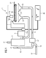
- FIG. 1 shows a schematic representation of a papermaking plant 1, as used in today's paper mills. Diluted with water in the ratio of about 1: 100, fibrous materials or fibrous materials are applied together with excipients to a sieve device 9 with a sieve 10. The fibrous materials are deposited on the screen 10 side by side and on each other. A circulating water 23 can be drained off or sucked off by means of a plurality of suction chamber regions 24 and returned to a cycle of the circulating water 23 in the flow direction S. Waste paper 30 and, as a rule, also pulp in dry form reach the paper mill as starting material, while pulp normally is produced in the same factory and used as a fiber / water mixture, ie one.
- the headbox 7 of the papermaking plant 1 distributes the pulp suspension uniformly over the entire wire width.
- the paper web 27 still contains about 80% water.
- the waste paper 30 ( FIG. 2 ) is thus used as a starting material for paper production in the papermaking plant 1, but has adhesive impurities, which according to the invention is to be eliminated.
- a plasma reactor 11a is arranged in the papermaking plant 1 between a sorter 5 and a headbox 7 in the piping system.
- the first plasma reactor 11a is integrated into the pipe system.
- an arrangement becomes FIG. 3 used.
- a second plasma reactor 11b is arranged above the sieve device 9 such that an intermediate product 39 or a pulp sprayed onto the sieve 10 comes into contact with the plasma.
- the inventive method is characterized in that preferably at the indicated locations the plasma reactors 11a, 11b are neutralized on the one hand in the pipe system of the circulating water 23 and on the other hand on the screening device 9, the adhesive impurities.
- a high voltage pulse generator 46 is individually connected to the plasma reactors 11a and 11b via high voltage lines.
- the plasma reactor 11a has two electrodes, as in FIG FIG. 3 shown.
- the plasma reactor 11b also has two electrodes, which, unlike the plasma reactor 11a, is similar in design to the plasma reactor 11a FIG. 13 illustrated arrangement. However, the basic principle is the same for any configuration of plasma reactors or generally electrode assembly.
- the high voltage pulse generator 46 generates by means of high voltage pulses 66, 67 (FIG. FIG. 4 ) a plasma between the electrodes of the reactors. Since a dielectric strength of water, especially of high conductivity water, as it has the circulating water 23 is very low, but increases dramatically with decreasing duration of the voltage load, short pulses with pulse durations of typically 10 microseconds, in some applications, only 1 microseconds needed , Typical values for the conductivity of the circulating water 23 in the paper industry are 4 to 5 ms / cm.
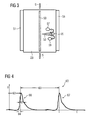
- FIG. 3 shows as a special embodiment of the FIG. 1 known plasma reactors 11a.
- the device in FIG. 3 is designed for the passage of the circulating water 23 in the flow direction S and simultaneous plasma generation in a treatment volume.
- a high voltage electrode 50 is arranged in the middle of a treatment volume.
- the outer jacket of the treatment volume is prepared as a counterelectrode 51.
- the circulating water 23 to be treated is located in the treatment volume.
- a streamer 53 is shown between the electrodes 50 and 51.
- Radicals 59 are generated in streamers by the collision of energetic electrons with molecules, thereby dissociating or exciting them. Upon dissociation, the radicals 59 are immediately released, while upon excitation by a subsequent radiant transition UV light is generated. This generated UV light in turn reacts with water molecules and dissociates them.
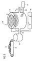
- FIG. 2 shows a second application example, a stock preparation plant 38.
- a waste paper 30 is conveyed via a conveyor belt 33 in the waste paper pulper 35.
- the waste paper dissolver 35 the waste paper 30 is mixed with water and pumped via a pipe 36 into a bleaching trough 37.
- a first electrode 43 and a second electrode 44 are each designed as a circular grid electrode.
- the first electrode 43 is arranged in the gas space of the pulp 39 filled in the bleaching trough 37.
- the second electrode 44 is arranged inside the bleaching trough 37 and is thus completely covered by the pulp 39. Between the two electrodes 43 and 44, a large-area cold plasma is generated by means of the high-voltage pulse generator 46.
- the radical OH in the pulp 39 preferably, O, O 3 produced.
- These radicals initiate a chemical reaction which changes the sticky impurities contained in the pulp as well as resins of primary pulp so in their surface structure that they no longer stick.
- the high voltage pulse generator 46 is operated to generate high voltage pulses of 1 ⁇ s duration between the electrodes 43 and 44.
- a necessary for the generation of radicals and ozone in the pulp fiber suspension DC voltage is about a few 10 kV to 100 kV.
- the high voltage pulses are superimposed on the DC voltage to form a total amplitude of a few 10 kV to over 100 kV.
- an oxygen-argon mixture which has been treated in a gas distributor 81, is introduced into the bleaching trough 37 via a gas line 80.
- FIG. 4 the voltage curve of the high voltage pulses used is shown.
- the abscissa shows the time in ms and the ordinate the voltage in kV. The units are chosen arbitrarily.
- a level a DC voltage can coincide with the abscissa shown.
- the illustrated pulse voltage U can therefore be superimposed preferably on a DC voltage, which is highly dependent on the conductivity of the respective aqueous medium.
- the pulses 66 and 67 have a pulse duration 62 of less than 1 microseconds, wherein the individual pulses 66, 67 preferably have a high rising edge with a rise time 64, which is significantly less than the pulse duration 62. The belonging to the pulse 66 or 67 falling edge is less pronounced.
- the pulse repetition time 63 is typically between 10 ⁇ s and 100 ms.
- the individual pulses 66, 67 have such a total amplitude that a predetermined energy density is achieved beyond a predetermined direct voltage.
- the pulse rise time 64 is usually short compared to the pulse fall time.
- FIG. 5 to FIG. 10 show further examples of electrode systems for generating plasma and / or corona discharges in preferably aqueous media, in particular for alternative use in the aforementioned embodiments.
- FIG. 5 For example, a plate-and-plate arrangement of a first plate 70a as an electrode and a second plate 70b as an electrode is illustrated.
- the first plate 70a and the second plate 70b are arranged parallel to each other.
- the first plate 70a forms the high voltage electrode and is connected to the high voltage pulse generator 46 via a high voltage cable.
- the second plate 70b forms the counter electrode and is connected as a grounded electrode to the high voltage pulse generator 46 in connection.
- FIG. 6 A corresponding arrangement with specially flat plate electrodes is in FIG. 6 shown. Again there are two solid plate electrodes 70a and 70c at a fixed distance, wherein a high voltage electrode 71 extends centrally. In this plate-wire plate assembly, the high voltage electrode 71 is made of a solid wire and connected to the high voltage output of the high voltage pulse generator 46. The grounded plates 70a, 70c are also in communication with the high voltage pulse generator 46.
- FIG. 7 shows a wire-tube arrangement as an electrode system.
- a high-voltage electrode 71 projects centrally into a cylindrical electrode 72.
- the high voltage electrode 71 is made as a solid wire and connected to the high voltage pulse generator 46.
- the cylindrical electrode 72 which is preferably configured as a wire mesh, is grounded and communicates with the high voltage pulse generator 46.
- FIG. 8 shows a tip-plate assembly as an electrode system.
- the example three tips 73 are connected via a high voltage line to the high voltage pulse generator 46.
- the tips 73 are arranged at right angles to a grounded plate electrode 74.
- the distance of the tip electrodes 73 to the plate electrode 74 is adjustable and thus can be adapted for different process conditions.
- FIG. 9 shows an electrode system assembly comprising 3 plates 70a, 70d and 70e.
- the first plate 70a which is connected as a high-voltage electrode to the high-voltage pulse generator 46, is arranged centrally between two solid plates 70d and 70e.
- the plates 70a and 70b are connected via a plate connector 70f. Since the plate 70d as a grounded counter electrode is in communication with the high voltage pulse generator 46, the plate 70e above the plate connector 70f also functions as a grounded counter electrode.
- FIG. 10 shows an electrode system as a grid-grid arrangement. Analogous to FIG. 5 here are a first grid 75a and a second grid 75b parallel to one another.
- the first grid 75a forms the high voltage electrode and is connected to the high voltage pulse generator 46.
- the second grid 75b forms the grounded counter electrode and also communicates with the high voltage pulse generator 46.
- a hybrid discharge wherein an electrode 75a is located completely outside the aqueous medium to be treated and a second electrode 76b is completely or partially immersed in the aqueous medium, is provided with the arrangement in FIG. 11 generated.
- the electrode 76a is implemented in this further embodiment for a plasma reactor as a grid electrode and communicates with the high voltage pulse generator 46 in connection.
- the grounded counter-electrode 76b is also designed as a grid electrode.
- FIG. 12 is as another embodiment of the FIG. 1 plasma reactor 11a, a tube, preferably a tube for transporting the circulating water 23 (FIG. FIG. 1 ) in the flow direction S, with an outer wall 77 in a section.
- a plate or grid arrangement with curved surfaces for adaptation to the outer wall or a vessel wall 77 is used as an electrode.
- a multiple wire electrode 79 is arranged as a concentric electrode following the course of the outer wall 77 and communicates with the high voltage pulse generator 46. It faces two counterelectrodes: on the one hand the vessel wall 77 and on the other hand a plate electrode 78.
- the high voltage electrode 79 is arranged without contact between the vessel wall 77 and the plate electrode 78.
- the vessel wall 77 and the plate electrode 78 are electrically conductively connected to each other and thus form the grounded counterelectrodes which are in communication with the high voltage pulse generator 46.
- FIG. 13 In order to generate pulsed discharges in the near-surface gas space, for example, above the sieve 10 or above the circulating water 23 is in FIG. 13 as another embodiment a special electrode arrangement shown.
- the circulating water 23 is guided in this case in an upwardly open circulating water channel 40.
- a high-voltage electrode 50 comprises a plurality of electrically connected rod electrodes and is arranged in the near-surface gas space of the circulating water 23 such that their rods run parallel to the surface of the circulating water 23.
- a grounded counter electrode 51 is designed as a solid plate and runs parallel to the over the entire surface of the high voltage electrode 50 at equidistant intervals distributed rod electrodes.
- a wall of the circulating water channel 40 could alternatively be designed as a counter electrode.
- FIG. 14 shows in a final embodiment a pulsed plasma or corona discharge system in an aqueous solution in a vessel, container, tub or tube.
- the electrode system is analogous to FIG. 3 formed as a coaxial wire tube electrode system.
- the high voltage electrode 50 is arranged coaxially with the counter electrode 51 forming the vessel wall.
- very fine gas beads are introduced into the discharge region via a gas line 80 by means of a gas distributor 81.
- gas bubbles 82 and 83 are preferably formed to FIG. 3 explained streamers. Owing to the streamer discharges, oxidants 57 are formed. Thus, certain radicals are generated in the circulating water 23.
Landscapes
- Life Sciences & Earth Sciences (AREA)
- Engineering & Computer Science (AREA)
- Wood Science & Technology (AREA)
- Physical Or Chemical Processes And Apparatus (AREA)
- Paper (AREA)
- Adhesives Or Adhesive Processes (AREA)
- External Artificial Organs (AREA)
Abstract
Description
Die Erfindung betrifft ein Verfahren zur Reduzierung klebender Verunreinigungen in einem Ausgangsstoff oder einem Zwischenprodukt bei der Papierherstellung, welches in wässriger Suspension oder einem Kreislaufwasser vorliegt. Ein derartiges Verfahren ist aus dem Dokument
Bei einem Recyclingvorgang von beispielsweise Altpapier als Ausgangsstoff gelangen aus dem Altpapier gelöste und feinstzerteilte "Stickies" in eine Papierherstellungsanlage. "Stickies" ist eine Bezeichnung für kleine Hotmelt- oder Klebstoff-Verunreinigungen, die später als Fehler im Papier oder in Pappe als beispielsweise störende Flecken auftreten. Insbesondere bei einer Altpapieraufbereitung wird das hierzu verwendete Wasser stark verunreinigt. Die klebenden Verunreinigungen in einem Faserstoff oder einer Faser-Suspension als Zwischenprodukt und in den allgemeinen Kreislaufwässern einer Papierherstellungsanlage neigen dazu, sich beispielsweise an Papiermaschinenbespannungen, wie Filzen und Sieben, sowie an Zylindern und Walzen abzulagern. Zusätzlich führen sie im letztendlich produzierten Papier zu Fehlstellen, die beispielsweise in der Weiterverarbeitung zu Störungen führen können oder deren Gebrauchswert einschränken.In a recycling process of, for example, waste paper as the starting material, dissolved and very finely divided "stickies" from the waste paper pass into a papermaking plant. "Stickies" is a term for small hotmelt or adhesive contaminants, which later appear as mistakes in the paper or in cardboard as, for example, disturbing stains. In particular, in a waste paper processing, the water used for this purpose is heavily contaminated. The adhesive contaminants in a pulp or fiber suspension as an intermediate and in the general circulation waters of a papermaking machine tend to deposit on, for example, papermachine clothing such as felting and sizing, as well as on cylinders and rollers. In addition, they lead to defects in the paper ultimately produced, which can lead to errors in the further processing or limit their use value.
Unter Zwischenprodukt sind Stoffe oder Güter zu verstehen, die bei der Papier- oder Kartonherstellung zwischen einem Ausgangsstoff und einem Endprodukt - dem heutigen Papier - entstehen oder erzeugt werden. Dies kann sowohl eine aufbereitete Stoffsuspension oder ein noch feuchtes Blatt Papier sein.Intermediate means substances or goods which are produced or produced in paper or board production between a starting material and an end product - today's paper. This can be either a prepared stock suspension or a still wet sheet of paper.
Diese klebenden Verunreinigungen stellen mittlerweile eines der größten Probleme bei der Wiederverwertung von Altpapier dar. Während so genannte Makro-Stickies mit Hilfe mechanischer Trennverfahren weitestgehend abgetrennt werden können, lassen sich so genannte Mikro-Stickies nur sehr schwer aus dem Wasserkreislauf entfernen. Mikro-Stickies sind so klein, dass sie auch ein Schlitzsieb mit ca. 100 µm Schlitzweite passieren können.These adhesive contaminants are now one of the biggest problems in the recycling of waste paper. While so-called macro-stickies can be largely separated using mechanical separation processes, so-called micro-stickies are very difficult remove the water cycle. Micro-Stickies are so small that they can also pass through a slot sieve with a slot width of approx. 100 μm.
Aber auch Harze in Primärfaserstoffen, wie Zellstoffe und Holzstoffe sowie Papierhilfsmittel mit einem hydrophoben Charakter führen regelmäßig zu klebenden Ablagerungen an Maschinenteilen und Papiermaschinenbespannungen. Eine Neigung derartiger Inhaltsstoffe klebende Ablagerungen zu bilden hängt von chemischen und physikalischen Randbedingungen, wie z.B. einer Temperatur, einem pH-Wert, einer Konzentration an gelösten und feinstverteilten Substanzen sowie einer hydraulischen Beanspruchung ab.However, resins in primary fiber materials, such as pulp and wood pulp and paper auxiliaries with a hydrophobic character regularly lead to sticky deposits on machine parts and paper machine clothing. An inclination to form adhesive deposits of such ingredients depends on chemical and physical constraints, such as e.g. a temperature, a pH, a concentration of dissolved and finely divided substances and a hydraulic stress.
Zur Reduzierung oder Vermeidung der Ablagerungen werden nach dem Stand der Technik folgende Methoden eingesetzt:
- Durch eine Zugabe mineralischer Adsorbentien, wie beispielsweise Talkum und Bentonite, können die klebenden Verunreinigungen maskiert und unschädlich gemacht werden,
- eine Zugabe kationischer Polymere, welche auch als ein Fixiermittel bezeichnet werden, zur Fixierung der klebenden Verunreinigungen an die Fasern der eingesetzten Faserstoffe, hierdurch werden Anhäufungen von klebrigen Verunreinigungen vermieden,
- eine Flockung und/oder eine Fällung sowie eine anschließende Abtrennung von suspendierten Substanzen nach einer Mikroflotation.
- By adding mineral adsorbents, such as talc and bentonites, the adhesive contaminants can be masked and rendered harmless,
- an addition of cationic polymers, which are also referred to as a fixing agent, for fixing the adhesive impurities to the fibers of the pulps used, thereby avoiding accumulations of sticky impurities,
- a flocculation and / or a precipitation and a subsequent separation of suspended substances after a microflotation.
Die zuvor genannten Methoden zur Reduzierung klebender Verunreinigungen nutzen die Zugabe von Hilfsstoffen. Eine Methode diese Hilfsstoffe in einer geeigneten Menge zu dosieren ist nicht bekannt. In der Regel werden die Hilfsstoffe überdosiert, dies führt zu einer erhöhten Kostenbelastung und zu einer zusätzlichen Belastung der Produktionskreisläufe (Verunreinigungen).The aforementioned methods for reducing sticky contaminants use the addition of auxiliaries. A method to dose these excipients in a suitable amount is not known. In general, the auxiliaries are overdosed, this leads to an increased cost burden and to an additional burden on the production cycles (impurities).
Die zur Verringerung der klebenden Verunreinigungen eingesetzten Hilfsstoffe greifen weiterhin in einen Ladungshaushalt der Papierherstellungsanlage ein und verändern beispielsweise bestimmte Entwässerungseigenschaften der Faserstoffsuspension und eine Zurückhaltung bzw. Retention von Füll- und Feinstoffen auf dem Papiermaschinensieb. Dieses veränderte Verhalten schlägt sich letztendlich negativ in der Papierqualität nieder.The adjuvants used to reduce the adhesive impurities continue to interfere with the charge balance of the papermaking equipment and, for example, alter certain dewatering properties of the pulp suspension and retention of fines and fines on the papermaking fabric. This changed behavior ultimately has a negative impact on paper quality.
Aufgabe der Erfindung ist es ein Verfahren bereitzustellen, welches es ermöglicht, die klebenden Verunreinigungen ohne Zusatz oder mit einem stark reduzierten Einsatz von Hilfsstoffen zu vermeiden.The object of the invention is to provide a method which makes it possible to avoid the adhesive impurities without addition or with a greatly reduced use of excipients.
Die Aufgabe wird mit dem eingangs genannten Verfahren dadurch gelöst, dass der Ausgangsstoff oder das Zwischenprodukt mit, vorzugsweise nicht thermischem, Plasma unter mindestens Atmosphärendruck in Kontakt gebracht wird. Durch eine Behandlung des Ausgangsstoffes oder des Zwischenproduktes, also der klebenden Verunreinigungen, wird eine Oberfläche der klebenden Verunreinigungen derart verändert, dass sie ihre klebenden Eigenschaften vermindern oder gänzlich verlieren. Dadurch wird mit Vorteil vermieden, dass die Verunreinigungen sich weiterhin an beispielsweise Bespannungen, Filzen, Walzen und in einer Trockenpartie ablagern.The object is achieved by the method mentioned above in that the starting material or the intermediate product with, preferably non-thermal, plasma is brought under at least atmospheric pressure in contact. By treating the starting material or the intermediate product, ie the adhesive impurities, a surface of the adhesive impurities is changed in such a way that they reduce or completely lose their adhesive properties. As a result, it is advantageously avoided that the contaminants continue to deposit on, for example, clothing, felts, rolls and in a dryer section.
Zweckmäßigerweise wird als Ausgangsstoff ein Altpapier verwendet. Insbesondere bei Altpapier treten nach der Auflösung, bedingt durch moderne Druckverfahren, neue wasserlösliche Farben, Glanzmittel, Bindemittel und verbesserten Klebstoff, beispielsweise für die Kartonherstellung, in einer hohen Konzentration die klebrigen Verunreinigungen als zum Teil mikroskopisch kleine Stickies auf.Conveniently, a waste paper is used as starting material. Particularly in the case of waste paper, after dissolution, due to modern printing processes, new water-soluble paints, brighteners, binders and improved adhesives, for example for paperboard production, occur in a high concentration as sticky impurities, some of them microscopic stickies.
Bei einer bevorzugten Ausgestaltung des Verfahrens werden keine Hilfsstoffe zum Zweck der Reduzierung der klebenden Verunreinigungen zugesetzt. Kann der Einsatz von Hilfsstoffen gänzlich vermieden werden, so ist dies ein entscheidender Kosten- und Umweltvorteil.In a preferred embodiment of the process, no auxiliaries are added for the purpose of reducing the adhesive contaminants. Can the use of excipients be avoided altogether, this is a decisive cost and environmental advantage.
In einer weiteren Ausführungsform der Erfindung werden Hilfsstoffe in einer Menge zugesetzt, die unter Berücksichtigung der Plasma-Applikation bemessen wird. Ist es nicht möglich gänzlich auf den Zusatz von Hilfsstoffen zu verzichten, so kann dennoch nur gerade so viel Hilfsstoff einem beispielsweise Siebwasser zugesetzt werden, dass bei quasi zeitgleicher Zugabe von Hilfsstoffen und der Plasma-Applikation, die klebenden Verunreinigungen eliminiert werden können.In a further embodiment of the invention, adjuvants are added in an amount which is dimensioned taking into account the plasma application. If it is not possible to dispense entirely with the addition of auxiliaries, then only just as much excipient can be added to, for example, white water, that the adhesive impurities can be eliminated with quasi-simultaneous addition of auxiliaries and the plasma application.
Vorzugsweise wird der Ausgangsstoff oder das Zwischenprodukt im Herstellungsprozess vor einem Stoffauflauf mit dem Plasma appliziert. Später auftretende, beispielsweise Blattqualitätsprobleme wie Löcher und eine reduzierte Festigkeit werden hierdurch verringert.Preferably, the starting material or the intermediate product is applied in the production process before a headbox with the plasma. Later occurring, for example, leaf quality problems such as holes and reduced strength are thereby reduced.
Mit Vorteil wird der Ausgangsstoff oder das Zwischenprodukt an zumindest einer Stelle zwischen einer Altpapierauflösungsvorrichtung und dem Stoffauflauf mit Plasma appliziert. Wird die Oberfläche der fasrigen Materialien bereits unmittelbar nach der Altpapierauflösung mit Plasma behandelt, können die reduzierten oder gänzlich eliminierten klebrigen Verunreinigungen den folgenden Maschinenlauf nicht mehr beeinflussen.Advantageously, the starting material or the intermediate product is applied to at least one point between a waste paper dissolving device and the headbox with plasma. If the surface of the fibrous materials is already treated with plasma immediately after the waste paper dissolution, the reduced or completely eliminated sticky impurities can no longer affect the subsequent machine run.
Zweckmäßig ist es weiterhin, dass der Ausgangsstoff oder das Zwischenprodukt unmittelbar nach einer mechanischen Reinigungsstufe im Herstellungsprozess, insbesondere nach einer letzten Reinigungsstufe, bevor der Ausgangsstoff oder das Zwischenprodukt für den Stoffauflauf verdünnt wird, mit Plasma appliziert wird. Maschinenlaufprobleme durch eine Ablagerung der klebenden Verunreinigungen und dadurch verursachte Abrisse einer Papierbahn, eine reduzierte Maschinengeschwindigkeit und eine hohe Stillstandszeit wegen der Reinigung der Ablagerungen werden somit verringert oder vermieden.It is expedient, furthermore, that the starting material or the intermediate product is applied with plasma immediately after a mechanical purification stage in the production process, in particular after a final purification stage, before the starting material or the intermediate product for the headbox is diluted. Machine downtime problems due to deposition of the sticky contaminants and thereby caused paper web breaks, reduced machine speed and high downtime due to debris cleaning are thus reduced or avoided.
Die bereits erwähnten Blattqualitätsprobleme werden mit besonderem Vorteil dadurch reduziert, dass direkt nach einem Aufspritzen einer Suspension auf ein Sieb, die Suspension mit dem kalten Plasma appliziert wird.The already mentioned leaf quality problems are reduced with particular advantage in that directly after spraying a suspension onto a sieve, the suspension is applied with the cold plasma.
Eine weitere Steigerung der späteren Qualitätseigenschaften des beispielsweise herzustellenden Papiers wird dadurch erreicht, dass das Plasma auf einen fließfähigen Vorhang aus der Suspension appliziert wird.A further increase in the later quality properties of the paper to be produced, for example, is achieved by applying the plasma to a flowable curtain from the suspension.
Für ein gutes Ergebnis ist es zweckmäßig, dass das Plasma in einem Abstand von kleiner als 20 cm, vorzugsweise kleiner als 10 cm, vorzugsweise kleiner als 5 cm, von der Suspension erzeugt wird.For a good result, it is expedient that the plasma is generated by the suspension at a distance of less than 20 cm, preferably less than 10 cm, preferably less than 5 cm.
In einer besonderen Ausgestaltung werden bei dem Verfahren zur Erzeugung des Plasmas zwischen Elektroden Hochspannungsimpulse mit einer Dauer von weniger als 10 µs erzeugt.In a particular embodiment, in the method for generating the plasma between electrodes, high-voltage pulses having a duration of less than 10 μs are generated.
Je nach Zusammensetzung des Ausgangsstoffes oder des Zwischenproduktes kann es zweckmäßig sein, zur Erzeugung des Plasmas Hochspannungsimpulse mit einer Dauer von 100 ns bis 1 µs zu verwenden.Depending on the composition of the starting material or of the intermediate product, it may be expedient to use high-voltage pulses with a duration of 100 ns to 1 μs for the generation of the plasma.
In einer bevorzugten Ausgestaltung werden im Plasma Radikale erzeugt, die auf den Ausgangsstoff oder auf das Zwischenprodukt einwirken. Die Erzeugung von Radikalen als chemisch aktive Substanzen wirkt sich vorteilhaft auf die Reduzierung klebender Verunreinigungen aus.In a preferred embodiment, radicals are generated in the plasma, which act on the starting material or on the intermediate product. The generation of radicals as chemically active substances has an advantageous effect on the reduction of adhesive impurities.
Weitere bevorzugte Ausgestaltungsmerkmale ergeben sich aus den weiteren Unteransprüchen.Further preferred design features emerge from the further subclaims.
Mehrere Ausführungsbeispiele sowie weitere Vorteile der Erfindung ergeben sich aus der nachfolgend beschriebenen Zeichnung, in deren
- FIG 1
- eine Papierherstellungsanlage mit Wasser- kreisläufen,
- FIG 2
- eine Stoffaufbereitungsanlage,
- FIG 3
- eine Darstellung (Schnitt) einer Anordnung zur Erzeugung von Radikalen in Koronaplasmen in einer wässrigen Lösung oder in Luft: Pa- rallelplatten- oder Rohranordnung mit Draht, dem eine gepulste Hochspannung überlagert wird,
- FIG 4
- eine Prinzipdarstellung von Impulsen zur Er- zeugung von Radikalen in Koronaentladungen in Luft oder wässrigen Medien bei Einsatz kurzer (typisch kleiner 1 µs) Hochspannungs- impulse mit hoher Impulswiederholrate,
- FIG 5 bis FIG 10
- Elektrodenanordnungen und Elektrodensysteme zur Erzeugung von Koronaentladungen: Platte- Platte-, Platte-Draht-Platte-, Koaxiale Draht-Rohr-, Spitze-Platte-, Mehrfachspit- zen-Platte-, Gitter-Platte (Rohr-, Gitter- Gitter-Anordnungen,
- FIG 11
- eine hybride Entladung, wobei sich eine E- lektrode vollständig oberhalb einer wässri- gen Lösung befindet, wogegen die zweite E- lektrode in die wässrige Lösung eingetaucht ist,
- FIG 12
- eine Platten- oder Gitteranordnung mit ge- krümmten Oberflächen zur Anpassung an Gefäß- wände bzw. Nutzung derselben als Elektrode, konzentrische Elektroden in Rohrform zur Nutzung der vorhandenen Verrohrung oder Tür- me für die Pulpe als Reaktorgefäß,
- FIG 13
- eine gepulste Entladung im oberflächennahen Raum der wässrigen Lösung,
- FIG 14
- ein gepulstes Koronaentladungssystem mit ko- axialem Draht-Rohr, mit eingeperlten, feinstverteilten Gasblasen, so dass im Ent- ladungsbereich feinste Gasperlen vorhanden sind und eine Streamerbildung vorwiegend in den Gasblasen abläuft,
- FIG. 1
- a paper production plant with water circuits,
- FIG. 2
- a stock preparation plant,
- FIG. 3
- a representation (section) of an arrangement for generating radicals in corona plasmas in an aqueous solution or in air: parallel plate or tube arrangement with wire, which is superimposed on a pulsed high voltage,
- FIG. 4
- a schematic representation of pulses for the generation of radicals in corona discharges in air or aqueous media with use of short (typically less than 1 μs) high-voltage pulses with high pulse repetition rate,
- FIG. 5 to FIG. 10
- Electrode arrangements and electrode systems for generating corona discharges: plate-plate, plate-wire-plate, coaxial wire-tube, tip-plate, multiple-tip plate, grid plate (tube, grid-grid arrangements .
- FIG. 11
- a hybrid discharge, wherein an electrode is completely above an aqueous solution, whereas the second electrode is immersed in the aqueous solution,
- FIG. 12
- a plate or grid arrangement with curved surfaces for adaptation to vessel walls or use thereof as electrode, concentric electrodes in tube form for use of the existing piping or towers for the pulp as reactor vessel,
- FIG. 13
- a pulsed discharge in the near-surface space of the aqueous solution,
- FIG. 14
- a pulsed corona discharge system with coaxial wire tube, with bubbled, finely distributed gas bubbles, so that the finest gas bubbles are present in the discharge area and a streamer formation takes place predominantly in the gas bubbles,
Einander entsprechende Teile sind in den
Der Stoffauflauf 7 der Papierherstellungsanlage 1 verteilt die Faserstoff-Suspension gleichmäßig über die gesamte Siebbreite. Am Ende der Siebvorrichtung 9 enthält die Papierbahn 27 noch immer ca. 80 % Wasser.The
Das Altpapier 30 (
Für eine Behandlung des Ausgangsstoffes oder des aufgelösten Altpapiers in einem Kreislaufwasser 23 ist in der Papierherstellungsanlage 1 zwischen einem Sortierer 5 und einem Stoffauflauf 7 im Rohrleitungssystem ein Plasmareaktor 11a angeordnet.For a treatment of the starting material or the dissolved waste paper in a circulating
Zur Reduzierung der klebenden Verunreinigungen im Kreislaufwasser 23 ist der erste Plasmareaktor 11a in das Rohrsystem integriert. Für die Integration in ein Rohrsystem wird eine Anordnung nach
Ein zweiter Plasmareaktor 11b ist oberhalb der Siebvorrichtung 9 derart angeordnet, dass ein auf das Sieb 10 gespritztes Zwischenprodukt 39 oder eine Pulpe mit dem Plasma in Kontakt kommt. Das erfindungsgemäße Verfahren zeichnet sich dadurch aus, dass vorzugsweise an den angegebenen Stellen die Plasmareaktoren 11a, 11b zum einen im Rohrsystem des Kreislaufwassers 23 und zum anderen über der Siebvorrichtung 9 die klebenden Verunreinigungen neutralisiert werden. Ein Hochspannungsimpulsgenerator 46 ist über Hochspannungsleitungen jeweils einzeln mit den Plasmareaktoren 11a und 11b verbunden. Der Plasmareaktor 11a weist zwei Elektroden auf, wie in
Der Hochspannungsimpulsgenerator 46 erzeugt mittels Hochspannungsimpulsen 66, 67 (
Die zweite Elektrode 44 ist im Inneren des Bleichtroges 37 angeordnet und wird damit vollständig von der Pulpe 39 bedeckt. Zwischen den beiden Elektroden 43 und 44 wird mittels des Hochspannungsimpulsgenerators 46 ein großflächiges kaltes Plasma erzeugt.The
Durch eine direkte Behandlung der Pulpe 39 mit dem kalten Plasma werden in der Pulpe 39 vorzugsweise die Radikale OH-, HOO-, O, O3 erzeugt. Diese Radikale lösen eine chemische Reaktion aus, welche die in der Pulpe enthaltenen klebrigen Verunreinigungen als auch Harze aus Primärfaserstoffen derart in ihrer Oberflächenstruktur verändert, dass sie nicht mehr kleben. Der Hochspannungsimpulsgenerator 46 wird derart betrieben, dass er Hochspannungsimpulse mit einer Dauer von 1 µs zwischen den Elektroden 43 und 44 erzeugt. Eine für die Erzeugung von Radikalen und Ozon in der Zellstofffaser-Suspension notwendige DC-Spannung liegt bei ca. einigen 10 kV bis 100 kV. Die Hochspannungsimpulse werden der DC-Spannung überlagert und bilden so eine Gesamtamplitude von einigen 10 kV bis über 100 kV. Durch die frühe Behandlung der Pulpe 39 mit einer kalten elektrischen Entladung, also dem Plasma, werden die Radikale in-situ erzeugt. So können große Gesamtmengen von Radikalen in die Pulpe 39 eingebracht werden. Die Radikale werden zudem feinstverteilt in der Suspension erzeugt, so dass auch der bisherige nötige Aufwand zur Mischung von Chemikalien mit der Suspension reduziert werden kann., HOO - - by direct treatment of the
Für eine weitere Steigerung der Reduzierung der klebenden Verunreinigungen wird in den Bleichtrog 37 über eine Gasleitung 80 ein Sauerstoff-Argon-Gemisch, welches in einem Gasverteiler 81 aufbereitet wurde, eingeleitet.For a further increase in the reduction of the adhesive contaminants, an oxygen-argon mixture, which has been treated in a
In
Die einzelnen Impulse 66,67 haben eine solche Gesamtamplitude, dass über eine vorgegebene Gleichspannung hinaus eine vorgegebene Energiedichte erreicht wird. Wie erwähnt, ist dabei meist die Impulsanstiegszeit 64 kurz im Vergleich zur Impulsabfallzeit. Durch eine solche Art der Impulse wird erreicht, dass elektrische Durchschläge, die zu räumlichen und zeitlichen Störungen in der homogenen Plasmadichteverteilung führen würden, vermieden werden.The
Eine entsprechende Anordnung mit speziell ebenen Plattenelektroden ist in
Eine hybride Entladung, wobei sich eine Elektrode 75a vollständig außerhalb des zu behandelnden wässrigen Mediums befindet und eine zweite Elektrode 76b ganz oder teilweise in das wässrige Medium eingetaucht ist, wird mit der Anordnung in
In
Um gepulste Entladungen im oberflächennahen Gasraum beispielsweise über dem Sieb 10 oder über dem Kreislaufwasser 23 zu erzeugen ist in
Claims (26)
- Method for reducing adhering impurities in a starting material (30) or an intermediate product (39) which is present in aqueous suspension or in a circulation water (23) in paper production,
characterised in that the starting material (30) or the intermediate product (39) is brought into contact with preferably non-thermal plasma under at least atmospheric pressure. - Method according to claim 1,
wherein recovered paper (30) is used as the starting material (30). - Method according to one of claims 1 or 2,
wherein no additives are added for the purpose of reducing the adhering impurities. - Method according to one of claims 1 or 2,
wherein additives are added in a quantity which is dimensioned taking into account the plasma application. - Method according to one of claims 1 to 4,
wherein the plasma is applied to the starting material (30) or the intermediate product (39) upstream of a headbox (7) during the production process. - Method according to one of claims 1 to 5,
wherein the plasma is applied to the starting material (30) or the intermediate product (39) at at least one position between a recovered paper dissolution device (35) and the headbox (7). - Method according to one of claims 1 to 5,
wherein the plasma is applied to the starting material (30) or the intermediate product (39) immediately after a mechanical cleaning stage in the production process, in particular after a final cleaning stage before the starting material (30) or the intermediate product (39) is diluted for the headbox (7). - Method according to one of claims 1 to 7,
wherein the plasma is applied to the intermediate product (39) directly after the intermediate product (39) has been sprayed onto a screen (10). - Method according to claim 8,
wherein the plasma is applied onto a free-flowing curtain composed of the intermediate product (39). - Method according to one of the preceding claims,
wherein the plasma is produced by means of an electrode (43,44) connected to a high-voltage pulse generator (46). - Method according to one of claims 8 to 10,
wherein the plasma is produced at a distance of less than 20 cm, preferably less than 10 cm, preferably less than 5 cm, from the intermediate product (39). - Method according to one of claims 10 to 11,
wherein high-voltage pulses (66,67) having a duration (62) of less than 10 µs are generated between electrodes (43,44; 47,48) for the purpose of producing the plasma. - Method according to claim 12,
wherein high-voltage pulses (66,67) having a duration (62) of 100 ns to 1 µs are used for the purpose of producing the plasma. - Method according to one of the preceding claims,
wherein radicals (59) are generated in the plasma which act on the starting material (30) or the intermediate product (39). - Method according to claim 14,
wherein ozone (O3), hydrogen peroxide (H2O2), OH, HO2 and/or HO2 - are generated as radicals (59). - Method according to one of claims 14 or 15,
wherein a rate of generation of the radicals (59) and/or a composition of the generated radicals (59) are/is controlled and/or regulated by influencing an amplitude (U), a pulse duration (62) and/or a pulse repetition rate (63) of the high-voltage pulses (66,67). - Method according to claim 16,
wherein a concentration of the generated radicals (59) is measured for the purpose of controlling and/or regulating the generation rate and/or the type of radicals (59) generated. - Method according to claim 17,
wherein the concentration is measured "online", in particular in real time. - Method according to one of claims 16 to 18,
wherein the pulse repetition rate (63) is set between 10 Hz and 5 kHz, in particular between 5 kHz and 10 kHz. - Method according to one of claims 16 to 19,
wherein a power injection of electrical energy into the plasma is controlled primarily via the regulation of the amplitude (U), the pulse duration (62) and the pulse repetition rate (63) of the high-voltage pulses superimposed on a DC voltage. - Method according to one of the preceding claims,
wherein a homogeneous, large-volume plasma with high power density is produced without plasma constrictions or breakdowns occurring. - Method according to one of claims 20 or 21,
wherein the DC voltage is applied at a level such that a stable DC corona discharge is formed in the plasma only in conjunction with the superimposed high-voltage pulses. - Method according to one of claims 20 to 22,
wherein the applied DC voltage lies below a voltage required for stable operation without high-voltage pulse superimposition. - Method according to one of claims 16 to 23,
wherein a total amplitude used (DC voltage + pulse amplitude) lies above a static breakdown voltage of the electrode arrangement. - Method according to claim 24,
wherein the total amplitude used is equivalent to two to five times the static breakdown voltage of the electrode arrangement. - Method according to one of claims 20 to 25,
wherein the amplitude (U) of the high-voltage pulses is equal to between 10% and 1000% of the applied DC voltage.
Applications Claiming Priority (2)
| Application Number | Priority Date | Filing Date | Title |
|---|---|---|---|
| DE102006024405A DE102006024405A1 (en) | 2006-05-24 | 2006-05-24 | Method for reducing adhesive contamination in papermaking |
| PCT/EP2007/054514 WO2007134973A2 (en) | 2006-05-24 | 2007-05-10 | Method for reducing adhering impurities in paper production |
Publications (2)
| Publication Number | Publication Date |
|---|---|
| EP2035621A2 EP2035621A2 (en) | 2009-03-18 |
| EP2035621B1 true EP2035621B1 (en) | 2010-06-30 |
Family
ID=38622179
Family Applications (1)
| Application Number | Title | Priority Date | Filing Date |
|---|---|---|---|
| EP07728966A Not-in-force EP2035621B1 (en) | 2006-05-24 | 2007-05-10 | Method for reducing adhering impurities in paper production |
Country Status (5)
| Country | Link |
|---|---|
| EP (1) | EP2035621B1 (en) |
| CN (1) | CN101501272B (en) |
| AT (1) | ATE472633T1 (en) |
| DE (2) | DE102006024405A1 (en) |
| WO (1) | WO2007134973A2 (en) |
Cited By (1)
| Publication number | Priority date | Publication date | Assignee | Title |
|---|---|---|---|---|
| US10519602B2 (en) | 2017-06-15 | 2019-12-31 | Ecolab Usa Inc. | Polymer for pitch and stickies deposition control in papermaking |
Families Citing this family (2)
| Publication number | Priority date | Publication date | Assignee | Title |
|---|---|---|---|---|
| FI123113B (en) * | 2008-09-10 | 2012-11-15 | Upm Kymmene Corp | Procedure for the manufacture of mechanical pulp and the use of mechanical pulp |
| CN105970714A (en) * | 2016-04-26 | 2016-09-28 | 玖龙纸业(天津)有限公司 | Descaling device in approach system |
Family Cites Families (6)
| Publication number | Priority date | Publication date | Assignee | Title |
|---|---|---|---|---|
| US5213661A (en) * | 1991-05-21 | 1993-05-25 | Air Products And Chemicals, Inc. | Oxygen alkali detackification in secondary fiber recovery |
| CA2268456A1 (en) * | 1996-11-01 | 1998-05-14 | George H. Miley | Plasma jet source using an inertial electrostatic confinement discharge plasma |
| DE19806732A1 (en) * | 1998-01-23 | 1999-07-29 | Voith Sulzer Papiertech Patent | Process for removing fine impurities from a fiber suspension |
| US6521134B1 (en) * | 1999-05-14 | 2003-02-18 | Institute Of Paper Science And Technology, Inc. | System and method for altering the tack of materials using an electrohydraulic discharge |
| AU2002339486B2 (en) * | 2001-05-21 | 2007-09-06 | Novozymes A/S | Use of lipolytic enzymes for stickies control |
| DE102005049230A1 (en) * | 2005-06-16 | 2006-12-28 | Siemens Ag | Process for the treatment of unwoven fibrous materials and apparatus for bleaching |
-
2006
- 2006-05-24 DE DE102006024405A patent/DE102006024405A1/en not_active Ceased
-
2007
- 2007-05-10 AT AT07728966T patent/ATE472633T1/en active
- 2007-05-10 WO PCT/EP2007/054514 patent/WO2007134973A2/en not_active Ceased
- 2007-05-10 DE DE502007004270T patent/DE502007004270D1/en active Active
- 2007-05-10 CN CN200780018856XA patent/CN101501272B/en not_active Expired - Fee Related
- 2007-05-10 EP EP07728966A patent/EP2035621B1/en not_active Not-in-force
Cited By (1)
| Publication number | Priority date | Publication date | Assignee | Title |
|---|---|---|---|---|
| US10519602B2 (en) | 2017-06-15 | 2019-12-31 | Ecolab Usa Inc. | Polymer for pitch and stickies deposition control in papermaking |
Also Published As
| Publication number | Publication date |
|---|---|
| WO2007134973A3 (en) | 2008-06-05 |
| EP2035621A2 (en) | 2009-03-18 |
| DE502007004270D1 (en) | 2010-08-12 |
| CN101501272B (en) | 2012-03-14 |
| CN101501272A (en) | 2009-08-05 |
| DE102006024405A1 (en) | 2007-11-29 |
| ATE472633T1 (en) | 2010-07-15 |
| WO2007134973A2 (en) | 2007-11-29 |
Similar Documents
| Publication | Publication Date | Title |
|---|---|---|
| WO2011098167A1 (en) | Wastewater purifying system | |
| EP2035621B1 (en) | Method for reducing adhering impurities in paper production | |
| EP2464783A1 (en) | Method for operating a sheet-forming unit, and sheet-forming unit | |
| EP1891266B1 (en) | Method for treating non-woven fibrous materials and bleaching device | |
| EP1896654B1 (en) | Sieve mechanism for the production of paper, and method for the treatment of nonwoven fibers | |
| EP2021541B1 (en) | Method for improving the quality of a fibrous pulp | |
| DE102006027677A1 (en) | Method for reducing impurities in a water system in the production of fabrics | |
| EP1891265B1 (en) | Method for treating a process material with large surface plasma | |
| EP1893803B9 (en) | Method for treating a process material during the production of paper, card, or cardboard | |
| DE102005049287A1 (en) | Screening device for the production of paper and process for the treatment of unwoven fibers | |
| EP1893809B1 (en) | Method and device for the improvement of paper quality | |
| EP1891267B1 (en) | Pressing device for compressing paper and/or for extracting carrier liquid from paper and method therefor | |
| DE2329021A1 (en) | Paper stock prepn - injection of steam or water to thin consistency by inducing turbulence | |
| WO2001004417A1 (en) | Use of talcum in the manufacture of paper and a method for the same | |
| EP2773813B1 (en) | Method for modifying the formation of a paper web and papermaking machine | |
| EP2886713B1 (en) | Method for treating paper fibres and paper fibre treating device | |
| DE102012204153A1 (en) | Reject system for handling waste product of e.g. machines to manufacture paper, has machine-pulpers in which product collected in storage, where stock consistency in one of pulpers is higher than stock consistency of remaining pulpers | |
| DE102013207491A1 (en) | Device for the treatment of liquid working media | |
| DE10303646A1 (en) | Process for removing impurities from an aqueous paper fiber suspension |
Legal Events
| Date | Code | Title | Description |
|---|---|---|---|
| PUAI | Public reference made under article 153(3) epc to a published international application that has entered the european phase |
Free format text: ORIGINAL CODE: 0009012 |
|
| 17P | Request for examination filed |
Effective date: 20081023 |
|
| AK | Designated contracting states |
Kind code of ref document: A2 Designated state(s): AT BE BG CH CY CZ DE DK EE ES FI FR GB GR HU IE IS IT LI LT LU LV MC MT NL PL PT RO SE SI SK TR |
|
| AX | Request for extension of the european patent |
Extension state: AL BA HR MK RS |
|
| DAX | Request for extension of the european patent (deleted) | ||
| GRAP | Despatch of communication of intention to grant a patent |
Free format text: ORIGINAL CODE: EPIDOSNIGR1 |
|
| GRAS | Grant fee paid |
Free format text: ORIGINAL CODE: EPIDOSNIGR3 |
|
| GRAA | (expected) grant |
Free format text: ORIGINAL CODE: 0009210 |
|
| AK | Designated contracting states |
Kind code of ref document: B1 Designated state(s): AT BE BG CH CY CZ DE DK EE ES FI FR GB GR HU IE IS IT LI LT LU LV MC MT NL PL PT RO SE SI SK TR |
|
| REG | Reference to a national code |
Ref country code: GB Ref legal event code: FG4D Free format text: NOT ENGLISH Ref country code: CH Ref legal event code: EP Ref country code: CH Ref legal event code: NV Representative=s name: SIEMENS SCHWEIZ AG |
|
| REG | Reference to a national code |
Ref country code: IE Ref legal event code: FG4D Free format text: LANGUAGE OF EP DOCUMENT: GERMAN |
|
| REF | Corresponds to: |
Ref document number: 502007004270 Country of ref document: DE Date of ref document: 20100812 Kind code of ref document: P |
|
| REG | Reference to a national code |
Ref country code: NL Ref legal event code: T3 |
|
| PG25 | Lapsed in a contracting state [announced via postgrant information from national office to epo] |
Ref country code: LT Free format text: LAPSE BECAUSE OF FAILURE TO SUBMIT A TRANSLATION OF THE DESCRIPTION OR TO PAY THE FEE WITHIN THE PRESCRIBED TIME-LIMIT Effective date: 20100630 Ref country code: SE Free format text: LAPSE BECAUSE OF FAILURE TO SUBMIT A TRANSLATION OF THE DESCRIPTION OR TO PAY THE FEE WITHIN THE PRESCRIBED TIME-LIMIT Effective date: 20100630 |
|
| LTIE | Lt: invalidation of european patent or patent extension |
Effective date: 20100630 |
|
| PG25 | Lapsed in a contracting state [announced via postgrant information from national office to epo] |
Ref country code: LV Free format text: LAPSE BECAUSE OF FAILURE TO SUBMIT A TRANSLATION OF THE DESCRIPTION OR TO PAY THE FEE WITHIN THE PRESCRIBED TIME-LIMIT Effective date: 20100630 Ref country code: SI Free format text: LAPSE BECAUSE OF FAILURE TO SUBMIT A TRANSLATION OF THE DESCRIPTION OR TO PAY THE FEE WITHIN THE PRESCRIBED TIME-LIMIT Effective date: 20100630 Ref country code: FI Free format text: LAPSE BECAUSE OF FAILURE TO SUBMIT A TRANSLATION OF THE DESCRIPTION OR TO PAY THE FEE WITHIN THE PRESCRIBED TIME-LIMIT Effective date: 20100630 |
|
| PG25 | Lapsed in a contracting state [announced via postgrant information from national office to epo] |
Ref country code: PL Free format text: LAPSE BECAUSE OF FAILURE TO SUBMIT A TRANSLATION OF THE DESCRIPTION OR TO PAY THE FEE WITHIN THE PRESCRIBED TIME-LIMIT Effective date: 20100630 |
|
| PG25 | Lapsed in a contracting state [announced via postgrant information from national office to epo] |
Ref country code: EE Free format text: LAPSE BECAUSE OF FAILURE TO SUBMIT A TRANSLATION OF THE DESCRIPTION OR TO PAY THE FEE WITHIN THE PRESCRIBED TIME-LIMIT Effective date: 20100630 |
|
| REG | Reference to a national code |
Ref country code: IE Ref legal event code: FD4D |
|
| PG25 | Lapsed in a contracting state [announced via postgrant information from national office to epo] |
Ref country code: SK Free format text: LAPSE BECAUSE OF FAILURE TO SUBMIT A TRANSLATION OF THE DESCRIPTION OR TO PAY THE FEE WITHIN THE PRESCRIBED TIME-LIMIT Effective date: 20100630 Ref country code: RO Free format text: LAPSE BECAUSE OF FAILURE TO SUBMIT A TRANSLATION OF THE DESCRIPTION OR TO PAY THE FEE WITHIN THE PRESCRIBED TIME-LIMIT Effective date: 20100630 Ref country code: PT Free format text: LAPSE BECAUSE OF FAILURE TO SUBMIT A TRANSLATION OF THE DESCRIPTION OR TO PAY THE FEE WITHIN THE PRESCRIBED TIME-LIMIT Effective date: 20101102 Ref country code: CZ Free format text: LAPSE BECAUSE OF FAILURE TO SUBMIT A TRANSLATION OF THE DESCRIPTION OR TO PAY THE FEE WITHIN THE PRESCRIBED TIME-LIMIT Effective date: 20100630 Ref country code: CY Free format text: LAPSE BECAUSE OF FAILURE TO SUBMIT A TRANSLATION OF THE DESCRIPTION OR TO PAY THE FEE WITHIN THE PRESCRIBED TIME-LIMIT Effective date: 20100630 Ref country code: IS Free format text: LAPSE BECAUSE OF FAILURE TO SUBMIT A TRANSLATION OF THE DESCRIPTION OR TO PAY THE FEE WITHIN THE PRESCRIBED TIME-LIMIT Effective date: 20101030 |
|
| PG25 | Lapsed in a contracting state [announced via postgrant information from national office to epo] |
Ref country code: IT Free format text: LAPSE BECAUSE OF FAILURE TO SUBMIT A TRANSLATION OF THE DESCRIPTION OR TO PAY THE FEE WITHIN THE PRESCRIBED TIME-LIMIT Effective date: 20100630 |
|
| PG25 | Lapsed in a contracting state [announced via postgrant information from national office to epo] |
Ref country code: DK Free format text: LAPSE BECAUSE OF FAILURE TO SUBMIT A TRANSLATION OF THE DESCRIPTION OR TO PAY THE FEE WITHIN THE PRESCRIBED TIME-LIMIT Effective date: 20100630 Ref country code: IE Free format text: LAPSE BECAUSE OF FAILURE TO SUBMIT A TRANSLATION OF THE DESCRIPTION OR TO PAY THE FEE WITHIN THE PRESCRIBED TIME-LIMIT Effective date: 20100630 |
|
| PLBE | No opposition filed within time limit |
Free format text: ORIGINAL CODE: 0009261 |
|
| STAA | Information on the status of an ep patent application or granted ep patent |
Free format text: STATUS: NO OPPOSITION FILED WITHIN TIME LIMIT |
|
| PG25 | Lapsed in a contracting state [announced via postgrant information from national office to epo] |
Ref country code: GR Free format text: LAPSE BECAUSE OF FAILURE TO SUBMIT A TRANSLATION OF THE DESCRIPTION OR TO PAY THE FEE WITHIN THE PRESCRIBED TIME-LIMIT Effective date: 20101001 |
|
| 26N | No opposition filed |
Effective date: 20110331 |
|
| PG25 | Lapsed in a contracting state [announced via postgrant information from national office to epo] |
Ref country code: ES Free format text: LAPSE BECAUSE OF FAILURE TO SUBMIT A TRANSLATION OF THE DESCRIPTION OR TO PAY THE FEE WITHIN THE PRESCRIBED TIME-LIMIT Effective date: 20101011 |
|
| REG | Reference to a national code |
Ref country code: DE Ref legal event code: R097 Ref document number: 502007004270 Country of ref document: DE Effective date: 20110330 |
|
| PG25 | Lapsed in a contracting state [announced via postgrant information from national office to epo] |
Ref country code: MC Free format text: LAPSE BECAUSE OF NON-PAYMENT OF DUE FEES Effective date: 20110531 Ref country code: MT Free format text: LAPSE BECAUSE OF FAILURE TO SUBMIT A TRANSLATION OF THE DESCRIPTION OR TO PAY THE FEE WITHIN THE PRESCRIBED TIME-LIMIT Effective date: 20100630 |
|
| PG25 | Lapsed in a contracting state [announced via postgrant information from national office to epo] |
Ref country code: LU Free format text: LAPSE BECAUSE OF NON-PAYMENT OF DUE FEES Effective date: 20110510 |
|
| PGFP | Annual fee paid to national office [announced via postgrant information from national office to epo] |
Ref country code: GB Payment date: 20130516 Year of fee payment: 7 |
|
| PGFP | Annual fee paid to national office [announced via postgrant information from national office to epo] |
Ref country code: NL Payment date: 20130503 Year of fee payment: 7 |
|
| PG25 | Lapsed in a contracting state [announced via postgrant information from national office to epo] |
Ref country code: TR Free format text: LAPSE BECAUSE OF FAILURE TO SUBMIT A TRANSLATION OF THE DESCRIPTION OR TO PAY THE FEE WITHIN THE PRESCRIBED TIME-LIMIT Effective date: 20100630 Ref country code: BG Free format text: LAPSE BECAUSE OF FAILURE TO SUBMIT A TRANSLATION OF THE DESCRIPTION OR TO PAY THE FEE WITHIN THE PRESCRIBED TIME-LIMIT Effective date: 20100930 |
|
| PGFP | Annual fee paid to national office [announced via postgrant information from national office to epo] |
Ref country code: BE Payment date: 20130619 Year of fee payment: 7 |
|
| PG25 | Lapsed in a contracting state [announced via postgrant information from national office to epo] |
Ref country code: HU Free format text: LAPSE BECAUSE OF FAILURE TO SUBMIT A TRANSLATION OF THE DESCRIPTION OR TO PAY THE FEE WITHIN THE PRESCRIBED TIME-LIMIT Effective date: 20100630 |
|
| PGFP | Annual fee paid to national office [announced via postgrant information from national office to epo] |
Ref country code: CH Payment date: 20130812 Year of fee payment: 7 |
|
| REG | Reference to a national code |
Ref country code: NL Ref legal event code: V1 Effective date: 20141201 |
|
| REG | Reference to a national code |
Ref country code: CH Ref legal event code: PL |
|
| GBPC | Gb: european patent ceased through non-payment of renewal fee |
Effective date: 20140510 |
|
| PG25 | Lapsed in a contracting state [announced via postgrant information from national office to epo] |
Ref country code: LI Free format text: LAPSE BECAUSE OF NON-PAYMENT OF DUE FEES Effective date: 20140531 Ref country code: CH Free format text: LAPSE BECAUSE OF NON-PAYMENT OF DUE FEES Effective date: 20140531 |
|
| PG25 | Lapsed in a contracting state [announced via postgrant information from national office to epo] |
Ref country code: NL Free format text: LAPSE BECAUSE OF NON-PAYMENT OF DUE FEES Effective date: 20141201 |
|
| PG25 | Lapsed in a contracting state [announced via postgrant information from national office to epo] |
Ref country code: GB Free format text: LAPSE BECAUSE OF NON-PAYMENT OF DUE FEES Effective date: 20140510 |
|
| REG | Reference to a national code |
Ref country code: FR Ref legal event code: PLFP Year of fee payment: 10 |
|
| PGFP | Annual fee paid to national office [announced via postgrant information from national office to epo] |
Ref country code: FR Payment date: 20160512 Year of fee payment: 10 Ref country code: AT Payment date: 20160407 Year of fee payment: 10 |
|
| PGFP | Annual fee paid to national office [announced via postgrant information from national office to epo] |
Ref country code: DE Payment date: 20160720 Year of fee payment: 10 |
|
| PG25 | Lapsed in a contracting state [announced via postgrant information from national office to epo] |
Ref country code: BE Free format text: LAPSE BECAUSE OF NON-PAYMENT OF DUE FEES Effective date: 20140531 |
|
| REG | Reference to a national code |
Ref country code: DE Ref legal event code: R119 Ref document number: 502007004270 Country of ref document: DE |
|
| REG | Reference to a national code |
Ref country code: AT Ref legal event code: MM01 Ref document number: 472633 Country of ref document: AT Kind code of ref document: T Effective date: 20170510 |
|
| PG25 | Lapsed in a contracting state [announced via postgrant information from national office to epo] |
Ref country code: AT Free format text: LAPSE BECAUSE OF NON-PAYMENT OF DUE FEES Effective date: 20170510 |
|
| REG | Reference to a national code |
Ref country code: FR Ref legal event code: ST Effective date: 20180131 |
|
| PG25 | Lapsed in a contracting state [announced via postgrant information from national office to epo] |
Ref country code: DE Free format text: LAPSE BECAUSE OF NON-PAYMENT OF DUE FEES Effective date: 20171201 |
|
| PG25 | Lapsed in a contracting state [announced via postgrant information from national office to epo] |
Ref country code: FR Free format text: LAPSE BECAUSE OF NON-PAYMENT OF DUE FEES Effective date: 20170531 |