EP1896654B1 - Sieve mechanism for the production of paper, and method for the treatment of nonwoven fibers - Google Patents
Sieve mechanism for the production of paper, and method for the treatment of nonwoven fibers Download PDFInfo
- Publication number
- EP1896654B1 EP1896654B1 EP06777289A EP06777289A EP1896654B1 EP 1896654 B1 EP1896654 B1 EP 1896654B1 EP 06777289 A EP06777289 A EP 06777289A EP 06777289 A EP06777289 A EP 06777289A EP 1896654 B1 EP1896654 B1 EP 1896654B1
- Authority
- EP
- European Patent Office
- Prior art keywords
- suspension
- plasma
- electrode
- high voltage
- radicals
- Prior art date
- Legal status (The legal status is an assumption and is not a legal conclusion. Google has not performed a legal analysis and makes no representation as to the accuracy of the status listed.)
- Not-in-force
Links
- 239000000835 fiber Substances 0.000 title claims abstract description 58
- 238000004519 manufacturing process Methods 0.000 title claims abstract description 11
- 238000000034 method Methods 0.000 title claims description 53
- 239000000725 suspension Substances 0.000 claims abstract description 80
- 239000000123 paper Substances 0.000 claims abstract description 49
- 239000007788 liquid Substances 0.000 claims abstract description 7
- 239000011087 paperboard Substances 0.000 claims abstract description 5
- 239000007789 gas Substances 0.000 claims description 24
- 229910052760 oxygen Inorganic materials 0.000 claims description 14
- XLYOFNOQVPJJNP-UHFFFAOYSA-N water Substances O XLYOFNOQVPJJNP-UHFFFAOYSA-N 0.000 claims description 14
- 230000015556 catabolic process Effects 0.000 claims description 11
- QVGXLLKOCUKJST-UHFFFAOYSA-N atomic oxygen Chemical compound [O] QVGXLLKOCUKJST-UHFFFAOYSA-N 0.000 claims description 9
- 239000001301 oxygen Substances 0.000 claims description 9
- 230000015572 biosynthetic process Effects 0.000 claims description 8
- 239000000203 mixture Substances 0.000 claims description 7
- 238000004061 bleaching Methods 0.000 claims description 6
- 238000001914 filtration Methods 0.000 claims description 6
- 230000008569 process Effects 0.000 claims description 6
- CBENFWSGALASAD-UHFFFAOYSA-N Ozone Chemical compound [O-][O+]=O CBENFWSGALASAD-UHFFFAOYSA-N 0.000 claims description 4
- 239000012159 carrier gas Substances 0.000 claims description 4
- 239000002657 fibrous material Substances 0.000 claims description 3
- 125000002887 hydroxy group Chemical group [H]O* 0.000 claims description 3
- MYMOFIZGZYHOMD-UHFFFAOYSA-N Dioxygen Chemical compound O=O MYMOFIZGZYHOMD-UHFFFAOYSA-N 0.000 claims description 2
- 150000003254 radicals Chemical class 0.000 claims 11
- MHAJPDPJQMAIIY-UHFFFAOYSA-N Hydrogen peroxide Chemical compound OO MHAJPDPJQMAIIY-UHFFFAOYSA-N 0.000 claims 2
- 230000003068 static effect Effects 0.000 claims 2
- 239000007844 bleaching agent Substances 0.000 claims 1
- 238000002347 injection Methods 0.000 claims 1
- 239000007924 injection Substances 0.000 claims 1
- 229910052756 noble gas Inorganic materials 0.000 claims 1
- 238000012545 processing Methods 0.000 abstract description 4
- 239000011111 cardboard Substances 0.000 abstract description 3
- 210000002381 plasma Anatomy 0.000 description 24
- 238000012216 screening Methods 0.000 description 9
- 239000007787 solid Substances 0.000 description 6
- 230000007704 transition Effects 0.000 description 6
- 230000005495 cold plasma Effects 0.000 description 5
- 238000001035 drying Methods 0.000 description 5
- XKRFYHLGVUSROY-UHFFFAOYSA-N Argon Chemical compound [Ar] XKRFYHLGVUSROY-UHFFFAOYSA-N 0.000 description 4
- 230000004888 barrier function Effects 0.000 description 3
- 238000004891 communication Methods 0.000 description 3
- 238000010276 construction Methods 0.000 description 3
- 239000001257 hydrogen Substances 0.000 description 3
- 229910052739 hydrogen Inorganic materials 0.000 description 3
- 229920005610 lignin Polymers 0.000 description 3
- 238000009832 plasma treatment Methods 0.000 description 3
- VVTSZOCINPYFDP-UHFFFAOYSA-N [O].[Ar] Chemical compound [O].[Ar] VVTSZOCINPYFDP-UHFFFAOYSA-N 0.000 description 2
- 239000012736 aqueous medium Substances 0.000 description 2
- 229910052786 argon Inorganic materials 0.000 description 2
- 230000000712 assembly Effects 0.000 description 2
- 238000000429 assembly Methods 0.000 description 2
- 230000008901 benefit Effects 0.000 description 2
- 238000006243 chemical reaction Methods 0.000 description 2
- 238000010494 dissociation reaction Methods 0.000 description 2
- 230000005593 dissociations Effects 0.000 description 2
- 230000005684 electric field Effects 0.000 description 2
- 230000005284 excitation Effects 0.000 description 2
- 239000004744 fabric Substances 0.000 description 2
- 125000000524 functional group Chemical group 0.000 description 2
- 230000001590 oxidative effect Effects 0.000 description 2
- 239000010893 paper waste Substances 0.000 description 2
- 239000002994 raw material Substances 0.000 description 2
- 230000008719 thickening Effects 0.000 description 2
- 229920001875 Ebonite Polymers 0.000 description 1
- 244000089486 Phragmites australis subsp australis Species 0.000 description 1
- 229910000831 Steel Inorganic materials 0.000 description 1
- 230000002745 absorbent Effects 0.000 description 1
- 239000002250 absorbent Substances 0.000 description 1
- 239000001913 cellulose Substances 0.000 description 1
- 229920002678 cellulose Polymers 0.000 description 1
- 239000002131 composite material Substances 0.000 description 1
- 230000006835 compression Effects 0.000 description 1
- 238000007906 compression Methods 0.000 description 1
- 238000013461 design Methods 0.000 description 1
- 238000009826 distribution Methods 0.000 description 1
- 230000000694 effects Effects 0.000 description 1
- 230000008030 elimination Effects 0.000 description 1
- 238000003379 elimination reaction Methods 0.000 description 1
- 239000000945 filler Substances 0.000 description 1
- 239000007792 gaseous phase Substances 0.000 description 1
- 239000010438 granite Substances 0.000 description 1
- TUJKJAMUKRIRHC-UHFFFAOYSA-N hydroxyl Chemical compound [OH] TUJKJAMUKRIRHC-UHFFFAOYSA-N 0.000 description 1
- 238000011065 in-situ storage Methods 0.000 description 1
- 239000011261 inert gas Substances 0.000 description 1
- 239000000463 material Substances 0.000 description 1
- 239000002609 medium Substances 0.000 description 1
- 125000000896 monocarboxylic acid group Chemical group 0.000 description 1
- 230000008092 positive effect Effects 0.000 description 1
- 238000002360 preparation method Methods 0.000 description 1
- 238000003825 pressing Methods 0.000 description 1
- 238000011084 recovery Methods 0.000 description 1
- 230000000630 rising effect Effects 0.000 description 1
- 239000010959 steel Substances 0.000 description 1
- 239000000126 substance Substances 0.000 description 1
- 230000002123 temporal effect Effects 0.000 description 1
Images
Classifications
-
- D—TEXTILES; PAPER
- D21—PAPER-MAKING; PRODUCTION OF CELLULOSE
- D21F—PAPER-MAKING MACHINES; METHODS OF PRODUCING PAPER THEREON
- D21F1/00—Wet end of machines for making continuous webs of paper
-
- D—TEXTILES; PAPER
- D21—PAPER-MAKING; PRODUCTION OF CELLULOSE
- D21H—PULP COMPOSITIONS; PREPARATION THEREOF NOT COVERED BY SUBCLASSES D21C OR D21D; IMPREGNATING OR COATING OF PAPER; TREATMENT OF FINISHED PAPER NOT COVERED BY CLASS B31 OR SUBCLASS D21G; PAPER NOT OTHERWISE PROVIDED FOR
- D21H25/00—After-treatment of paper not provided for in groups D21H17/00 - D21H23/00
- D21H25/08—Rearranging applied substances, e.g. metering, smoothing; Removing excess material
- D21H25/12—Rearranging applied substances, e.g. metering, smoothing; Removing excess material with an essentially cylindrical body, e.g. roll or rod
- D21H25/14—Rearranging applied substances, e.g. metering, smoothing; Removing excess material with an essentially cylindrical body, e.g. roll or rod the body being a casting drum, a heated roll or a calender
Definitions
- the invention relates to a screening device for removing carrier liquid from a fiber suspension in the production of paper, cardboard or cardboard.
- the invention relates to a method for treating unwoven fibers in a suspension, in particular as pulp or pulp, while the suspension is screened or withdrawn from its carrier liquid, preferably for operation of the screening device according to the invention.
- the fiber suspension leaves a headbox and passes from there to a, preferably revolving, sieve (wire or sieve cylinder).
- a sieve wire or sieve cylinder
- the sheet is dewatered to a dry content of preferably 16 to 25%.
- the filtration is a sharp transition between an already formed fiber mat and the overlying fiber suspension.
- the concentration of fibers increases steadily from top to bottom.
- Strength of the leaf increases with increasing drainage.
- Paper fibers preferably consist of numerous cellulose chains with many OH groups. The strength of the paper is created by intervening water molecules, which connect the fibers via hydrogen bonds. The number of hydrogen bonds can be increased by compression or slight stretching, e.g. in a press section.
- the invention has for its object to provide an apparatus and a method to increase the processing speed in papermaking.
- the device-related object is achieved according to the invention in that above, in or below a sieve region of the sieve device at least one first electrode is arranged, which is connected to a high-voltage pulse generator, wherein in the fiber suspension or in its immediate vicinity, a plasma generated is.
- the fiber suspension is treated with plasma with advantage in view of the later material properties even before sheet formation has been completed.
- the plasma is generated at a distance of less than 20 cm, preferably less than 10 cm, preferably less than 5 cm, from the fiber suspension.
- the direct treatment of the fiber suspension preferably pulp fibers, with cold plasma are preferably generated in the gas space of the fiber suspension certain radicals. These radicals promote an increase in the strength of the paper.
- a particularly advantageous embodiment of the invention is that a sieve is prepared as an electrode.
- At least one second electrode for plasma generation is present.
- An arrangement of at least two electrodes allows a two-sided treatment of the fiber suspension or of the non-pressed sheet.
- the electrodes are arranged in the immediate vicinity of a suction chamber region, in particular a wet suction region or a flat suction region.
- a suction chamber region in particular a wet suction region or a flat suction region.
- first electrode and the second electrode are arranged in the immediate vicinity of the Saughunt Scheme that the fiber suspension is guided between the electrodes.
- a two-sided treatment of the fiber suspension improves the treatment result, which is achieved by means of the screening device according to the invention.
- the electrodes are prepared in such a way that a gas discharge through the electrodes or past the electrodes, in particular through the fiber suspension, is sucked.
- the device can be designed with a means for introducing gas, in particular air or oxygen, preferably pure oxygen or oxygen with, for example, inert gas as the carrier gas, between or in the immediate vicinity of the electrodes.
- gas in particular air or oxygen, preferably pure oxygen or oxygen with, for example, inert gas as the carrier gas
- a carrier gas e.g. Argon
- At least one electrode is designed as a plate.
- an electrode arrangement with two plates can be used with advantage for a two-sided application of plasma to the suspension curtain.
- the suspension is brought into contact with preferably non-thermal, large-area plasma under at least atmospheric pressure, that plasma is generated in the immediate vicinity of the suspension or in the suspension or in the immediate vicinity of the suspension, a gas discharge, in particular a corona discharge, is generated under at least atmospheric pressure.
- Radicals may, inter alia, also trigger bleaching chemical reactions, in particular free oxygen O, in particular also a hydroxyl radical OH, in particular ozone O 3 , as well as free functional groups such as OH groups, COOH groups.
- These functional groups play a key role, in particular in increasing the bonding strength of the fibers to one another, which further improves a tear resistance of the paper and thus the possible processing speed.
- a series of differently oxidizing and functionalizing radicals are generated in a gaseous phase and used to treat these fibers with radicals in the non-pressed sheet, still on the wire, or immediately thereafter in the first part of a press section.
- this treatment should be used at a content of carrier liquid of 75% to over 98%.
- the strength of the paper and thus the maximum possible working speed is thereby increased at an early stage.
- this type of treatment also bleaches the colored substances lying on the surface, for example the adhering lignin or dye residues are oxidatively decolorized.
- Radicals are generated in gas discharges by high-energy electrons collide with molecules and thereby dissociate or excite them and so to the formation of radicals to lead. In the dissociation, radicals are released immediately, while in the excitation by subsequent radiant transitions UV light is generated, which in turn reacts with and preferably dissociates air and water molecules.
- eV electron volts
- UV light is generated, which in turn reacts with and preferably dissociates air and water molecules.
- eV electron volts
- streamers are discharge channels that are under construction and form due to the applied high external field strengths. An assembly of such streamer takes place within less than 10 ns and then rapidly merges into a thermal breakdown channel.
- the pulse duration is significantly shorter than corresponds to a construction time of a complete breakdown in the respective medium.
- the use of such short high voltage pulses has been found to be particularly advantageous, whereas the use of radio frequency (RF) or microwave pulses or high voltage single pulses of more than 10 ⁇ s in duration, as in US Pat WO 2004/101891 A1 described, is far less efficient. The reason is probably a quick transition from one. Streamer for breakthrough at atmospheric pressure, in particular in the presence of geometric irregularities on the paper surface, such as individual fibers on which the electric field is greatly increased.
- RF radio frequency
- the paper web or the fiber suspension is located between the electrodes used for the streamer discharge, this is particularly advantageous since the paper or the fiber suspension thereby acts in part as a dielectric barrier.
- the dielectric barrier makes it easier to control the transition from the streamer to the breakdown.
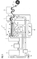
- FIG. 1 shows a schematic representation of a papermaking plant 1, as used in today's paper mills. Their construction and the combination of different aggregates are determined by the type of paper, board and paperboard types to be produced, as well as the raw materials used.
- the papermaking plant 1 has a spatial extent of about 10 m in width and about 120 m in length.
- the papermaking plant produces up to 1400 m of paper per minute 27. It only takes a few seconds from the first impact of the fiber suspension or pulp 39 on the screening device 9 to the finished paper 27, which is finally rolled up in a reel 15. Diluted with water at a ratio of 1: 100, the fibrous materials 30 are applied together with auxiliaries to the sieve device 9 with the sieve 10.
- the fibers are deposited on the screen 10 side by side and on each other.
- the white water 23 can drain or be sucked off by means of several suction chamber regions 24. This results in a uniform fiber composite, which is further dehydrated by mechanical pressure in a press device 11 and with the aid of steam heat.
- the entire papermaking process is essentially subdivided into the areas of stock preparation, paper machine, finishing and equipment.
- Waste paper and, as a rule, also pulp reach a paper mill in dry form, while pulp is normally produced in the same factory and pumped into the material center 3 as a fiber / water mixture, ie a suspension of unvarnished pulp. Waste paper and pulp 30 are also dissolved in a fiber trough 35 with the addition of water. Non-paper components are discharged via various sorting aggregates (not shown here). In the fabric center 3, depending on the desired type of paper, the mixture of different raw materials. Fillers and auxiliaries are also added here to improve paper quality and increase productivity.
- the headbox 7 of the papermaking plant 1 distributes the pulp suspension uniformly over the entire wire width.
- the paper web 27 still contains about 80% water.
- Another dewatering process is carried out by mechanical pressure in the press device 11.
- the paper web 27 is guided by means of an absorbent endless felt cloth between rolls of steel, granite or hard rubber and thereby dehydrated.
- the white water 23 received by the suction chamber section 24 is returned to a sorter 5 and to another part to a cloth catcher 17.
- the press device 11 is followed by a drying system 13.
- the remaining residual water is evaporated in the drying plant 13.
- the paper web 27 passes through several steam-heated drying cylinders. In the end, the paper 27 has a residual moisture of a few percent.
- the water vapor formed in the drying plant 13 is sucked off and passed into a heat recovery system, not shown.
- a first electrode 43 below the sieve device 9 and a second electrode 44 above the sieve device 9 are arranged between the headbox 7 and the beginning region of the sieve device 9 according to the invention.
- the electrodes 43 and 44 are arranged such that the surface-distributed fiber suspension 39 extends between them. So that a large-area plasma under atmospheric pressure in the immediate vicinity of the fiber suspension 39 can be produced for the treatment of the fiber suspension 39, the electrodes 43 and 44 are connected to a high-voltage pulse generator 46. With the aid of this high-voltage pulse generator 46, a large-volume plasma with a large cross section and with high power density is produced between the electrodes 43 and 44.
- a plasma density is homogeneously distributed over the treatment area which is covered by the electrodes 43 and 44.
- this Large-volume plasma with high power density generated by the fact that a DC corona discharge intensive, short-lasting high voltage pulses are superimposed with a high pulse repetition rate of typically about 1 kHz.
- a very homogeneous, large-volume plasma with a high power density is produced without the plasma constrictions that are known in DC corona discharges.
- oxygen with argon as the carrier gas is introduced into the treatment space between the electrodes 43 and 44 by means of a gas distributor 81.
- Hydroxyl radicals are particularly advantageously produced with the aid of the oxygen-argon mixture. Hydroxyl radicals are particularly aggressive and oxidizing, thereby increased strength in the later sheet formation is achieved at the only a few seconds in the treatment area between the electrodes 43 and 44 lingering fiber suspension.
- an electrode system 47, 48 in the press device 11 generates a large-area plasma for the treatment of the paper web 27.
- the first electrode 47 in the press apparatus 11 is designed as a semicircular grid electrode. Due to the semicircular configuration of the electrode 47, it can follow the course of the paper web over a transport roller 12.
- the second electrode 48 in the press device 11 is configured as a plate electrode and arranged such that the transport roller 12 can be guided between the electrodes 47 and 48.
- the plasma treatment area is flown via the gas distributor 81 with the gas line 80 with an oxygen-argon mixture.
- the pressing process compacts the paper structure, the strength is increased again and a surface quality is decisively influenced.
- the molecular structure of the paper surface is further altered.
- printability is improved.
- a streamer is a special form of a linearly moving plasma cloud or a developing discharge channel that forms due to the excited high external field strength. An assembly of such streamer takes place within less than 10 ns and merges very quickly into a thermal breakdown channel.
- the aforementioned arrangements of the electrode systems, with the paper web 27 between the electrodes used for the streamer discharge, are particularly advantageous, as the paper 27 thereby partially acts as a dielectric barrier, thereby suppressing the transition from the streamer to the breakdown.
- the radical OH in the suspension 39 is preferably, O, O 3 produced. In addition to an increase in strength, these radicals trigger a bleaching chemical reaction.
- the high voltage pulse generator 46 is operated to generate high voltage pulses having a duration of typically 1 ⁇ sec. generated between the electrodes 43 and 44. A necessary for the generation of radicals and ozone in the pulp mill suspension DC voltage is about a few 10 kV to about 100 kV. The high voltage pulses are superimposed on the DC voltage and thus form a total amplitude of typically about 100 kV. By treating the pulp fiber suspension 39 with a cold electrical discharge, so the plasma, the radicals are generated in situ. Thus, large total amounts of radicals can be introduced into the suspension 39.
- the high voltage pulse generator is operated to generate high voltage pulses having a duration of typically 0.1 ⁇ s to a few ⁇ s.
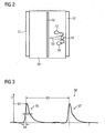
- FIG. 2 shows as a further embodiment, a sectional view of an arrangement for generating radicals.
- a high voltage electrode 50 is arranged in the center of the arrangement.
- the outer jacket of the assembly is prepared as a counter electrode 51.
- the arrangement contains a pulp fiber suspension 39 to be screened.
- a streamer 53 is shown between the electrodes 50 and 51. Radicals are generated in streamers by high-energy electrons colliding with and dissociating or exciting molecules. Upon dissociation, radicals 59 are immediately released, while upon excitation by a subsequent radiant transition, UV light is generated. This generated UV light in turn reacts with water molecules and dissociates them.
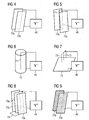
- FIG. 3 is the applied voltage waveform of the high voltage pulses shown.
- a first pulse 66 and a second pulse 67 each having a pulse width 62, have a spacing of one pulse repetition time 63.
- the abscissa shows the time in ms and the ordinate the voltage in kV. The units are chosen arbitrarily.
- a level of typically about 100 kV DC voltage coincides with the abscissa shown.
- the illustrated pulse voltage is thus superimposed on the DC voltage.
- the pulses 66 and 67 have a pulse width 62 of less than 1 microseconds, wherein the individual pulses 66, 67 have a steeply rising edge with a rise time 64 and a less steeply sloping edge.
- the pulse repetition time 63 is typically between 10 ⁇ s and 100 ms.
- the individual pulses 66, 67 have such a total amplitude that a predefined energy density is achieved beyond the predetermined direct voltage.
- the pulse rise time 64 is short compared to the pulse fall time.
- FIG. 4 to FIG. 9 show examples of electrode systems for generating corona discharges in preferably aqueous media.
- a plate-and-plate arrangement of a first plate 70a as an electrode and a second plate 70b as an electrode is illustrated.
- the first plate 70a and the second plate 70b are arranged parallel to each other.
- the first plate 70a forms the high voltage electrode and is connected to the high voltage pulse generator 46 via a high voltage cable.
- the second plate 70b forms the counter electrode and is connected as a grounded electrode to the high voltage pulse generator 46 in connection.
- FIG. 5 A corresponding arrangement with specially flat plate electrodes is in FIG. 5 shown. Again there are two solid plate electrodes 70a and 70c at a fixed distance with a high voltage electrode 71 in the middle.
- the high voltage electrode 71 is made of a solid wire and connected to the high voltage output of the high voltage pulse generator 46.
- the grounded plates 70a, 70c are also in communication with the high voltage pulse generator.
- FIG. 6 shows a wire-tube arrangement as an electrode system.
- a high-voltage electrode 71 projects centrally into a cylindrical electrode 72.
- the high voltage electrode 71 is made as a solid wire and connected to the high voltage pulse generator 46.
- the cylindrical electrode 72 which is preferably configured as a wire mesh, is grounded and communicates with the high voltage pulse generator 46.
- FIG. 7 shows a tip-plate assembly as an electrode system.
- Three tips 73 are over a high voltage line with the high voltage pulse generator 46 connected.
- the tips 73 are arranged at right angles to a grounded plate electrode 74.
- the distance of the tip electrodes 73 to the plate electrode 74 is adjustable and thus can be adapted for different process conditions.
- FIG. 8 shows an electrode system assembly comprising 3 plates 70a, 70d and 70e.
- the first plate 70a which is connected as a high-voltage electrode to the high-voltage pulse generator 46, is arranged centrally between two solid plates 70d and 70e.
- the plates 70a and 70b are connected via a plate connector 70f. Since the plate 70d as a grounded counter electrode is in communication with the high voltage pulse generator 46, the plate 70e above the plate connector 70f also functions as a grounded counter electrode.
- FIG. 9 shows an electrode system as a grid-grid arrangement. Analogous to FIG. 4 Here, a first grid 75a and a second grid 75b are parallel to each other.
- the first grid 75a forms the high voltage electrode and is connected to the high voltage pulse generator 46.
- the second grid 75b forms the grounded counter electrode and communicates with the high voltage pulse generator 46.
- a hybrid discharge wherein an electrode 75a is located entirely outside a fiber suspension 39 to be treated and a second electrode 75b is wholly or partially immersed in the fiber suspension 39 is provided with an alternative arrangement in which the screen is configured as electrode 75a is generated.
- the screen is designed as a grid electrode and forms the high voltage electrode which is connected to the high voltage pulse generator 46.
- the grounded counter electrode 76 b is designed as a grid electrode and is in communication with the high voltage pulse generator 46.
- a high-voltage electrode comprising a plurality of electrically connected rod electrodes is arranged in the near-surface gas space of the fiber suspension 39 such that their rods extend parallel to the surface.
- a grounded counter electrode is designed as a solid plate and arranged in distributed over the entire surface equidistant distances from the high voltage electrode.
Landscapes
- Paper (AREA)
- Preliminary Treatment Of Fibers (AREA)
- Physical Or Chemical Processes And Apparatus (AREA)
- Chemical Or Physical Treatment Of Fibers (AREA)
Abstract
Description
Die Erfindung betrifft eine Siebvorrichtung zum Entziehen von Trägerflüssigkeit aus einer Faser-Suspension bei der Herstellung von Papier, Pappe oder Karton.The invention relates to a screening device for removing carrier liquid from a fiber suspension in the production of paper, cardboard or cardboard.
Des Weiteren betrifft die Erfindung ein Verfahren zur Behandlung unverwobener Faserstoffe in einer Suspension, insbesondere als Pulpe oder Faserbrei, während die Suspension gesiebt oder ihr Trägerflüssigkeit entzogen wird, vorzugsweise zum Betrieb der Siebvorrichtung nach der Erfindung.Furthermore, the invention relates to a method for treating unwoven fibers in a suspension, in particular as pulp or pulp, while the suspension is screened or withdrawn from its carrier liquid, preferably for operation of the screening device according to the invention.
In einer Papierherstellungsanlage oder in Teilen einer Papierherstellungsanlage verlässt die Faser-Suspension einen Stoffauflauf und gelangt von dort auf ein, vorzugsweise umlaufendes, Sieb (Langsieb oder Siebzylinder). Auf dem Sieb wird das Blatt bis zu einem Trockengehalt von vorzugsweise 16 bis 25 % entwässert. Während der Entwässerung treten zwei verschiedene Arten einer Blattbildung auf: Filtration und Eindickung. Die Filtration ist ein scharfer Übergang zwischen einer schon gebildeten Fasermatte und der darüber liegenden Faser-Suspension. Bei der Eindickung nimmt die Konzentration von Faserstoffen von oben nach unten hin stetig zu. Eine Festigkeit des Blattes nimmt mit zunehmender Entwässerung zu. Papierfasern bestehen vorzugsweise aus zahlreichen Zelluloseketten mit vielen OH-Gruppen. Die Festigkeit des Papiers entsteht über dazwischen liegende Wassermoleküle, die die Fasern über Wasserstoffbrücken miteinander verbinden. Die Anzahl der Wasserstoffbrücken kann durch Pressung oder leichte Streckung gesteigert werden, z.B. in einer Pressenpartie.In a papermaking plant or in parts of a papermaking plant, the fiber suspension leaves a headbox and passes from there to a, preferably revolving, sieve (wire or sieve cylinder). On the wire, the sheet is dewatered to a dry content of preferably 16 to 25%. During drainage, two different types of foliation occur: filtration and thickening. The filtration is a sharp transition between an already formed fiber mat and the overlying fiber suspension. During thickening, the concentration of fibers increases steadily from top to bottom. Strength of the leaf increases with increasing drainage. Paper fibers preferably consist of numerous cellulose chains with many OH groups. The strength of the paper is created by intervening water molecules, which connect the fibers via hydrogen bonds. The number of hydrogen bonds can be increased by compression or slight stretching, e.g. in a press section.
Aus
Aus
Der Erfindung liegt die Aufgabe zugrunde, eine Vorrichtung und ein Verfahren zur Verfügung zu stellen, um die Verarbeitungsgeschwindigkeit bei der Papierherstellung zu steigern.The invention has for its object to provide an apparatus and a method to increase the processing speed in papermaking.
Die vorrichtungsbezogene Aufgabe wird gemäß der Erfindung dadurch gelöst, dass über, in oder unter einem Siebbereich der Siebvorrichtung mindestens eine erste Elektrode angeordnet ist, welche mit einem Hochspannungs-Impulsgenerator verbunden ist, wobei in der Faser-Suspension oder in ihrer unmittelbaren Umgebung ein Plasma erzeugbar ist.The device-related object is achieved according to the invention in that above, in or below a sieve region of the sieve device at least one first electrode is arranged, which is connected to a high-voltage pulse generator, wherein in the fiber suspension or in its immediate vicinity, a plasma generated is.
Durch die Behandlung der Fasern auf dem Sieb, vorzugsweise vor der eigentlichen Blattbildung, mit einem, vorzugsweise kalten Koronaplasma, wird die molekulare Struktur der Faseroberflächen verändert. Dadurch werden folgende positive Effekte erzielt:
- Erhöhung der Festigkeit des Blattes noch vor einer Pressenpartie,
- Beseitigung von, farbigen "Molekülgruppen" (insbesondere Lignin und restlichen Farbstoffmolekülen aus dem Kreislaufwasser) an der Oberfläche und eine zeitgleiche Aufhellung des Papiers.
- Increasing the strength of the sheet before a press section,
- Elimination of colored "molecular groups" (in particular lignin and residual dye molecules from the circulating water) on the surface and a simultaneous lightening of the paper.
Insbesondere durch die Erhöhung der Festigkeit des Blattes können bei der Papierherstellung höhere Verarbeitungsgeschwindigkeiten erzielt werden. Ebenso wird die Wahrscheinlichkeit von Papierrissen reduziert. Im Bereich der Siebvorrichtung wird die Faser-Suspension noch vor abgeschlossener Blattbildung mit Vorteil im Hinblick auf die späteren Materialeigenschaften mit Plasma behandelt.In particular, by increasing the strength of the sheet, higher processing speeds can be achieved in papermaking. Likewise, the probability of paper breaks is reduced. In the area of the screening device, the fiber suspension is treated with plasma with advantage in view of the later material properties even before sheet formation has been completed.
Zweckmäßig ist, dass das Plasma in einem Abstand von kleiner als 20 cm, vorzugsweise kleiner als 10 cm, vorzugsweise kleiner als 5 cm, von der Faser-Suspension erzeugt wird. Durch die direkte Behandlung der Faser-Suspension, vorzugsweise Zellstofffasern, mit kalten Plasma werden vorzugsweise im Gasraum der Faser-Suspension bestimmte Radikale erzeugt. Diese Radikale begünstigen eine Festigkeitssteigerung des Papiers.It is expedient that the plasma is generated at a distance of less than 20 cm, preferably less than 10 cm, preferably less than 5 cm, from the fiber suspension. By the direct treatment of the fiber suspension, preferably pulp fibers, with cold plasma are preferably generated in the gas space of the fiber suspension certain radicals. These radicals promote an increase in the strength of the paper.
Eine besonders vorteilhafte Ausgestaltung der Erfindung ist, dass ein Sieb als eine Elektrode hergerichtet ist. Durch die Behandlung mit vorzugsweise kaltem Plasma auf dem Sieb entstehen zu einem frühen Zeitpunkt im Blatt mehr Wasserstoffbrückenbindungen als ohne die Plasmabehandlung. Die Festigkeit des Blattes auf dem Sieb nimmt daher weiter zu. Die früher erreichte Festigkeit des Blattes reduziert die Gefahr von Papierrissen weiter.A particularly advantageous embodiment of the invention is that a sieve is prepared as an electrode. By treatment with preferably cold plasma on the screen, more hydrogen bonds are formed at an early stage in the leaf than without the plasma treatment. The strength of the sheet on the wire therefore continues to increase. The previously achieved strength of the sheet further reduces the risk of paper tears.
Zweckmäßig ist, dass mindestens eine zweite Elektrode zur Plasmaerzeugung vorhanden ist. Eine Anordnung von mindestens zwei Elektroden ermöglicht eine beidseitige Behandlung der Faser-Suspension bzw. des ungepressten Blattes.It is expedient that at least one second electrode for plasma generation is present. An arrangement of at least two electrodes allows a two-sided treatment of the fiber suspension or of the non-pressed sheet.
In einer bevorzugten Ausführungsform der Erfindung sind die Elektroden in unmittelbarer Nähe von einem Saugkammerbereich, insbesondere einem Nasssaugbereich oder einem Flachsaugbereich, angeordnet. Vorteilhafterweise erfolgt die Plasmabehandlung des noch ungepressten Faserbreis auf dem Sieb in den Saugkammerbereichen (Flachsauger, Nasssauger). Dadurch wird eine radikalenhaltige Luft aus einem Plasmareaktorbereich oberhalb des Siebes durch den Faserbrei bzw. die Faser-Suspension hindurchgesaugt und es entsteht eine besonders innige Verbindung zwischen radikalenhaltiger Luft und der Faseroberfläche.In a preferred embodiment of the invention, the electrodes are arranged in the immediate vicinity of a suction chamber region, in particular a wet suction region or a flat suction region. Advantageously, the plasma treatment of the still unpressed pulp on the screen in the Saugkammerbereichen (flat suction, wet suction). As a result, a radical-containing air is sucked out of a plasma reactor region above the sieve through the pulp or the fiber suspension and a particularly intimate connection is formed between radical-containing air and the fiber surface.
Zweckmäßig ist dabei, falls die erste Elektrode und die zweite Elektrode derart in unmittelbarer Nähe von dem Saugkammerbereich angeordnet sind, dass die Faser-Suspension zwischen den Elektroden geführt ist. Eine beidseitige Behandlung der Faser-Suspension verbessert das Behandlungsergebnis, welches mittels der erfindungsgemäßen Siebvorrichtung erreicht wird.It is expedient, if the first electrode and the second electrode are arranged in the immediate vicinity of the Saugkammerbereich that the fiber suspension is guided between the electrodes. A two-sided treatment of the fiber suspension improves the treatment result, which is achieved by means of the screening device according to the invention.
Vorzugsweise sind die Elektroden derart hergerichtet, dass eine Gasentladung durch die Elektroden oder an den Elektroden vorbei, insbesondere durch die Faser-Suspension hindurch, saugbar ist.Preferably, the electrodes are prepared in such a way that a gas discharge through the electrodes or past the electrodes, in particular through the fiber suspension, is sucked.
Weiterhin kann die Vorrichtung mit einem Mittel zum Einleiten von Gas, insbesondere Luft oder Sauerstoff, vorzugsweise reinem Sauerstoff oder Sauerstoff mit beispielsweise Edelgas als Trägergas, zwischen oder in die unmittelbare Nähe der Elektroden ausgestaltet sein. Durch diese vorteilhafte Anordnung werden, vorzugsweise fein verteilte Luftblasen oder Sauerstoff oder Sauerstoff mit einem Trägergas wie z.B. Argon, in die Faser-Suspension eingeströmt. Mit Hilfe dieses eingeströmten Gases und der gleichzeitigen Behandlung mit Plasma wird die spätere Reißfestigkeit des Papiers weiter erhöht.Furthermore, the device can be designed with a means for introducing gas, in particular air or oxygen, preferably pure oxygen or oxygen with, for example, inert gas as the carrier gas, between or in the immediate vicinity of the electrodes. By virtue of this advantageous arrangement, preferably finely divided air bubbles or oxygen or oxygen are mixed with a carrier gas, e.g. Argon, flowed into the fiber suspension. With the help of this infused gas and the simultaneous treatment with plasma, the subsequent tear strength of the paper is further increased.
Zweckmäßig ist ferner, dass mindestens eine Elektrode als Platte ausgestaltet ist. Bei einer vorzugsweise fließenden Suspension, insbesondere ein herabfallender Vorhang aus Suspension, kann eine Elektrodenanordnung mit zwei Platten mit Vorteil für ein beidseitiges Applizieren von Plasma auf den Suspensions-Vorhang genutzt werden.It is also expedient that at least one electrode is designed as a plate. In a preferably flowing suspension, in particular a falling curtain of suspension, an electrode arrangement with two plates can be used with advantage for a two-sided application of plasma to the suspension curtain.
Weitere Ausgestaltungsmerkmale der Siebvorrichtung, insbesondere der Elektrodenanordnungen der Siebvorrichtung, sind durch die Patentansprüche 10 bis 16 wiedergegeben.Further design features of the screening device, in particular the electrode arrangements of the screening device, are represented by the
Nach der verfahrensseitigen Maßgabe der Erfindung ist vorgesehen, dass die Suspension mit vorzugsweise nichtthermischen, großflächigem Plasma unter mindestens Atmosphärendruck in Kontakt gebracht, dass Plasma in unmittelbarer Nähe zur Suspension erzeugt oder in der Suspension oder in unmittelbarer Umgebung der Suspension eine Gasentladung, insbesondere eine Koronaentladung, unter mindestens Atmosphärendruck erzeugt wird.According to the method on the side of the invention, it is provided that the suspension is brought into contact with preferably non-thermal, large-area plasma under at least atmospheric pressure, that plasma is generated in the immediate vicinity of the suspension or in the suspension or in the immediate vicinity of the suspension, a gas discharge, in particular a corona discharge, is generated under at least atmospheric pressure.
Bei der Behandlung der rohen noch weitgehend ungebundenen Papieroberfläche mit kaltem Plasma kurz vor dem Sieb, auf dem Sieb oder unmittelbar danach, beispielsweise im ersten Teil der Pressenpartie, werden bestimmte Radikale erzeugt (z.B. OH-, HOO-, O, O3), welche mit der Papieroberfläche und insbesondere der Faser-Suspension chemisch reagieren.In the treatment of the raw still largely unbound paper surface with cold plasma just before the sieve, on the Sieve or immediately thereafter, for example in the first part of the press section, certain radicals are generated (eg OH - , HOO - , O, O 3 ), which react chemically with the paper surface and in particular the fiber suspension.
Weitere bevorzugte Verfahrensmerkmale sind durch die Patentansprüche 18 bis 54 beschrieben. Diesen liegen u.a. folgende Überlegungen zu Grunde:Further preferred method features are described by the claims 18 to 54. These are u.a. the following considerations apply:
Radikale können unter anderem auch bleichende chemische Reaktionen auslösen, insbesondere freier Sauerstoff O, insbesondere auch ein Hydroxyl-Radikal OH, insbesondere Ozon O3, als auch freie funktionelle Gruppen wie z.B. OH-Gruppen, COOH-Gruppen. Diese funktionalen Gruppen wiederum sind maßgeblich daran beteiligt, insbesondere die Bindungsfestigkeit der Fasern untereinander zu erhöhen, wodurch sich eine Reißfestigkeit des Papiers und damit die mögliche Verarbeitungsgeschwindigkeit weiter verbessert.Radicals may, inter alia, also trigger bleaching chemical reactions, in particular free oxygen O, in particular also a hydroxyl radical OH, in particular ozone O 3 , as well as free functional groups such as OH groups, COOH groups. These functional groups, in turn, play a key role, in particular in increasing the bonding strength of the fibers to one another, which further improves a tear resistance of the paper and thus the possible processing speed.
Vorzugsweise wird bei einer simultanen Erzeugung von Radikalen eine Reihe von unterschiedlich oxidierenden und funktionalisierenden Radikalen in einer Gasphase erzeugt und dazu verwendet, im ungepressten Blatt, noch auf dem Sieb oder unmittelbar danach im ersten Teil einer Pressenpartie diese Fasern mit Radikalen zu behandeln.Preferably, with a simultaneous generation of radicals, a series of differently oxidizing and functionalizing radicals are generated in a gaseous phase and used to treat these fibers with radicals in the non-pressed sheet, still on the wire, or immediately thereafter in the first part of a press section.
Insbesondere soll diese Behandlung bei einem Gehalt an Trägerflüssigkeit von 75 % bis zu über 98 % eingesetzt werden. Die Festigkeit des Papiers und damit die maximale mögliche Arbeitsgeschwindigkeit wird dadurch schon frühzeitig erhöht. Des Weiteren lassen sich durch diese Art der Behandlung auch die an der Oberfläche liegenden farbigen Stoffe bleichen, beispielsweise werden das anhaftende Lignin oder Farbstoffreste oxidativ entfärbt.In particular, this treatment should be used at a content of carrier liquid of 75% to over 98%. The strength of the paper and thus the maximum possible working speed is thereby increased at an early stage. Furthermore, this type of treatment also bleaches the colored substances lying on the surface, for example the adhering lignin or dye residues are oxidatively decolorized.
Radikale werden in Gasentladungen dadurch erzeugt, dass energiereiche Elektronen mit Molekülen zusammenstoßen und diese dadurch dissoziieren oder anregen und so zur Radikalenbildung führen. Bei der Dissoziation werden unmittelbar Radikale freigesetzt, während bei der Anregung durch anschließende strahlende Übergänge UV-Licht erzeugt wird, welches wiederum mit vorzugsweise Luft- und Wassermolekülen reagiert und diese dissoziiert. Um ausreichend energiereiche Elektronen im Bereich von ca. 5 eV (Elektronenvolt) bis > 15 eV zu erhalten, werden extrem hohe elektrische Felder benötigt. Diese hohen Feldstärken treten insbesondere am Kopf von sogenannten Streamern auf. Streamer sind Entladungskanäl, die sich im Aufbau befinden und sich aufgrund der angelegten hohen externen Feldstärken ausbilden. Ein Aufbau solcher Streamer findet innerhalb weniger 10 ns statt und geht dann schnell in einen thermischen Durchschlagskanal über. Da in einem thermischen Durchschlagskanal keine energiereichen Elektronen gebildet werden, ist es unter anderem das Ziel, diese thermischen Durchschläge zu vermeiden oder auf ein Minimum zu reduzieren. Um eine gute Energieeffizienz der Erzeugung von vorzugsweise Radikalen in Gasen zu erhalten, ist es daher erforderlich, mit sehr kurzen Hochspannungseinzelimpulsen zu arbeiten. Vorzugsweise ist die Pulsdauer deutlich kürzer als es einer Aufbauzeit eines vollständigen Durchschlages im jeweiligen Medium entspricht.Radicals are generated in gas discharges by high-energy electrons collide with molecules and thereby dissociate or excite them and so to the formation of radicals to lead. In the dissociation, radicals are released immediately, while in the excitation by subsequent radiant transitions UV light is generated, which in turn reacts with and preferably dissociates air and water molecules. To obtain sufficiently high-energy electrons in the range of about 5 eV (electron volts) to> 15 eV, extremely high electric fields are required. These high field strengths occur in particular at the head of so-called streamers. Streamer are discharge channels that are under construction and form due to the applied high external field strengths. An assembly of such streamer takes place within less than 10 ns and then rapidly merges into a thermal breakdown channel. Since no high-energy electrons are formed in a thermal breakdown channel, among other things, the goal is to avoid these thermal breakdowns or to reduce them to a minimum. In order to obtain a good energy efficiency of the generation of preferably radicals in gases, it is therefore necessary to work with very short single high-voltage pulses. Preferably, the pulse duration is significantly shorter than corresponds to a construction time of a complete breakdown in the respective medium.
Eine gepulste Koronaentladung direkt oberhalb des Papiers oder an der Faser-Suspension unter Benutzung extrem kurzer Hochspannungsimpulse von weniger als 10 µs, insbesondere typisch von 1 µs, und besondere vorteilhaft deutlich geringer als 1 µs, mit Spannungen von einigen kV bis zu über 100 kV, abhängig von einem Abstand der Elektroden zum Papier oder zur Faser-Suspension und der Eigenschaften des Papiers, wird mit Vorteil, hinsichtlich der Qualitätseigenschaften, auf das Papier oder die Faser-Suspension appliziert. Insbesondere hat sich die Verwendung von derartig kurzen Hochspannungsimpulsen als besonders vorteilhaft gezeigt, wogegen die Verwendung von Radiofrequenz-(RF-) oder Mikrowellenimpulsen oder von Hochspannungseinzelimpulsen mit mehr als 10 µs Dauer, wie in
Befindet sich die Papierbahn oder die Faser-Suspension zwischen den zur Streamerentladung benutzten Elektroden, so ist dies besonders vorteilhaft, da das Papier oder die Faser-Suspension dadurch teilweise als eine dielektrische Barriere wirkt. Durch die dielektrische Barriere lässt sich der Übergang vom Streamer zum Durchschlag besser kontrollieren.If the paper web or the fiber suspension is located between the electrodes used for the streamer discharge, this is particularly advantageous since the paper or the fiber suspension thereby acts in part as a dielectric barrier. The dielectric barrier makes it easier to control the transition from the streamer to the breakdown.
Bevorzugte, jedoch keinesfalls einschränkende Ausführungsbeispiele der Erfindung werden nunmehr anhand der Zeichnung näher erläutert. Zur Verdeutlichung ist die Zeichnung nicht maßstäblich ausgeführt, und gewisse Merkmale sind nur schematisiert dargestellt. Einander entsprechende Teile sind in den Figuren mit denselben Bezugszeichen versehen. Im Einzelnen zeigt die
- FIG 1
- eine schematische Darstellung einer Papierherstellungsanlage mit einer Siebvorrichtung nach der Erfindung, einer Pressenvorrichtung und einer Veredelungsund/oder Trockenanlage,
- FIG 2
- eine Darstellung (Schnitt) einer Anordnung zur Erzeugung von Radikalen in Koronaplasmen in Pulpe oder Luft: Parallelplatten- oder Rohranordnung mit Draht, dem eine gepulste Hochspannung überlagert wird,
- FIG 3
- eine Prinzipdarstellung von Impulsen zur Erzeugung von Radikalen in Koronaentladungen in Luft oder wässrigen Medien bei Einsatz kurzer (typisch < 1 µs) Hochspannungsimpulse mit hoher Impulswiederholrate, und
- FIG 4
- bis
FIG 9 Elektrodenanordnungen und Elektrodensysteme zur Erzeugung von Koronaentladungen: Platte-Platte-, Platte-Draht-Platte-, koaxiale Draht-Rohr-, SpitzePlatte-, Mehrfachspitzen-Platte-, Gitter-Platte (Rohr)-, Gitter-Gitter-Anordnungen.
- FIG. 1
- a schematic representation of a papermaking plant with a screening device according to the invention, a press device and a finishing and / or drying plant,
- FIG. 2
- a representation (section) of an arrangement for generating radicals in corona plasmas in pulp or air: parallel plate or tube arrangement with wire, which is superimposed on a pulsed high voltage,
- FIG. 3
- a schematic representation of pulses for generating radicals in corona discharges in air or aqueous media using short (typically <1 microseconds) high voltage pulses with high pulse repetition rate, and
- FIG. 4
- to
FIG. 9 Electrode assemblies and electrode systems for generating corona discharges: plate-plate, plate-wire-plate, coaxial wire-tube, tip-plate, multi-tip-plate, grid-plate (tube), grid-grid assemblies.
Altpapier und in der Regel auch Zellstoff erreichen eine Papierfabrik in trockener Form, während Holzstoff normalerweise im gleichen Werk erzeugt und als Faser-/Wasser-Mischung, also einer Suspension aus unverwobenen Faserstoffen, in die Stoffzentrale 3 gepumpt werden. Altpapier und Zellstoff 30 werden ebenfalls unter Zugabe von Wasser in einem Fasertrog 35 aufgelöst. Papierfremde Bestandteile werden über verschiedene Sortieraggregate ausgeschleust (hier nicht dargestellt). In der Stoffzentrale 3 erfolgt je nach gewünschter Papiersorte die Mischung der verschiedenen Rohstoffe. Hier werden auch Füll- und Hilfsstoffe zugegeben, die der Verbesserung der Papierqualität und der Erhöhung der Produktivität dienen.Waste paper and, as a rule, also pulp reach a paper mill in dry form, while pulp is normally produced in the same factory and pumped into the material center 3 as a fiber / water mixture, ie a suspension of unvarnished pulp. Waste paper and pulp 30 are also dissolved in a fiber trough 35 with the addition of water. Non-paper components are discharged via various sorting aggregates (not shown here). In the fabric center 3, depending on the desired type of paper, the mixture of different raw materials. Fillers and auxiliaries are also added here to improve paper quality and increase productivity.
Der Stoffauflauf 7 der Papierherstellungsanlage 1 verteilt die Faserstoff-Suspension gleichmäßig über die gesamte Siebbreite. Am Ende der Siebvorrichtung 9 enthält die Papierbahn 27 noch immer ca. 80 % Wasser.The headbox 7 of the papermaking plant 1 distributes the pulp suspension uniformly over the entire wire width. At the end of the
Ein weiterer Entwässerungsprozess erfolgt durch mechanischen Druck in der Pressenvorrichtung 11. Dabei wird die Papierbahn 27 mittels eines saugfähigen endlosen Filztuches zwischen Walzen aus Stahl, Granit oder Hartgummi hindurchgeführt und dadurch entwässert. Das durch den Saugkammerbereich 24 aufgenommene Siebwasser 23 wird zu einem Teil zu einem Sortierer 5 und zu einem anderen Teil zu einem Stofffänger 17 zurückgeführt. An die Pressenvorrichtung 11 schließt sich eine Trocknungsanlage 13 an. Das verbleibende Restwasser wird in der Trocknungsanlage 13 verdampft. Slalomartig durchläuft die Papierbahn 27 mehrere dampfbeheizte Trockenzylinder. Am Ende hat das Papier 27 eine Restfeuchte von wenigen Prozent. Der in der Trocknungsanlage 13 entstandene Wasserdampf wird abgesaugt und in eine nicht dargestellte Wärmerückgewinnungsanlage geführt.Another dewatering process is carried out by mechanical pressure in the
Für eine Behandlung der Faser-Suspension 39 nach dem erfindungsgemäßen Verfahren sind zwischen dem Stoffauflauf 7 und dem Anfangsbereich der Siebvorrichtung 9 nach der Erfindung eine erste Elektrode 43 unter der Siebvorrichtung 9 und eine zweite Elektrode 44 über der Siebvorrichtung 9 angeordnet. Die Elektroden 43 und 44 sind derart angeordnet, dass die flächig verteilte Faser-Suspension 39 zwischen ihnen verläuft. Damit zur Behandlung der Faser-Suspension 39 ein großflächiges Plasma unter Atmosphärendruck in unmittelbarer Nähe zu der Faser-Suspension 39 erzeugt werden kann, sind die Elektroden 43 und 44 mit einem Hochspannungsimpulsgenerator 46 verbunden. Mit Hilfe dieses Hochspannungsimpulsgenerators 46 wird zwischen den Elektroden 43 und 44 ein großvolumiges Plasma mit einem großen Querschnitt und mit hoher Leistungsdichte hergestellt. Hierbei ist eine Plasmadichte homogen über den Behandlungsbereich, welcher durch die Elektroden 43 und 44 abgedeckt wird, verteilt. Erfindungsgemäß wird dieses großvolumige Plasma mit hoher Leistungsdichte dadurch erzeugt, dass einer DC-Korona-Entladung intensive, kurz andauernde Hochspannungsimpulse mit einer hohen Impulswiederholrate von typisch ca. 1 kHz überlagert werden. Bei dieser Betriebsweise wird ein äußerst homogenes, großvolumiges Plasma mit einer hohen Leistungsdichte erzeugt, ohne dass es zu den bei DC-Korona-Entladungen bekannten Plasmaeinschnürungen kommt.For a treatment of the
Um die Behandlungswirkung, welche das kalte großflächige Plasma auf die Faser-Suspension 39 ausübt, zu unterstützen wird mittels eines Gasverteilers 81 über eine Gasleitung 80 Sauerstoff mit Argon als Trägergas in den Behandlungsraum zwischen die Elektroden 43 und 44 eingeleitet. Mit Hilfe des Sauerstoff-Argon-Gemisches werden besonders vorteilhaft Hydroxyl-Radikale erzeugt. Hydroxyl-Radikale sind besonders aggressiv und oxidierend, dadurch wird an der nur wenige Sekunden im Behandlungsbereich zwischen den Elektroden 43 und 44 verweilenden Faser-Suspension eine erhöhte Festigkeit bei der späteren Blattbildung erzielt.In order to support the treatment effect which the cold large-area plasma exerts on the
Analog zu dem zuvor beschriebenen wird mit einem Elektrodensystem 47, 48 in der Pressenvorrichtung 11 ein großflächiges Plasma zur Behandlung der Papierbahn 27 erzeugt. Die erste Elektrode 47 in der Pressenvorrichtung 11 ist als eine halbrunde Gitterelektrode ausgeführt. Durch die halbrunde Ausgestaltung der Elektrode 47 kann sie dem Papierbahnverlauf über einer Transportrolle 12 folgen. Die zweite Elektrode 48 in der Pressenvorrichtung 11 ist als eine Plattenelektrode ausgestaltet und derart angeordnet, dass die Transportrolle 12 zwischen den Elektroden 47 und 48 geführt werden kann. Um auch hier die Radikalbildung im Plasma anzuregen, wird der Plasmabehandlungsbereich über den Gasverteiler 81 mit der Gasleitung 80 mit einem Sauerstoff-Argon-Gemisch angeströmt.Analogous to that described above, an
Der Pressvorgang verdichtet das Papiergefüge, die Festigkeit wird nochmals erhöht und eine Oberflächengüte wird entscheidend beeinflusst. Durch die Behandlung des gepressten Papiers mit kaltem Plasma, insbesondere mit den erzeugten Radikalen, wird die molekulare Struktur der Papieroberfläche weiter verändert. Zusätzlich zur Festigkeit des Papiers 27 wird eine Bedruckbarkeit verbessert.The pressing process compacts the paper structure, the strength is increased again and a surface quality is decisively influenced. By the treatment of the pressed paper with cold plasma, especially with the generated radicals, the molecular structure of the paper surface is further altered. In addition to the strength of the
Mit den vorbenannten Elektrodenanordnungen 43 und 44 sowie 47 und 48 ist es nach dem erfindungsgemäßen Verfahren möglich die Papierbahn 27 zwischen Streamer-Entladungen zu führen.With the above-mentioned
Ein Streamer ist eine spezielle Form einer sich linear fortbewegenden Plasmawolke oder ein in der Entwicklung befindlicher Entladungskanal, der sich aufgrund der angeregten hohen externen Feldstärke ausbildet. Ein Aufbau solcher Streamer findet innerhalb weniger 10 ns statt und geht sehr schnell in einen thermischen Durchschlagskanal über. Vorbenannte Anordnungen der Elektrodensysteme, wobei sich die Papierbahn 27 zwischen den zur Streamer-Entladung benutzten Elektroden befindet, ist besonders vorteilhaft, da das Papier 27 dadurch teilweise als eine dielektrische Barriere fungiert, wodurch sich der Übergang vom Streamer zum Durchschlag unterdrücken lässt.A streamer is a special form of a linearly moving plasma cloud or a developing discharge channel that forms due to the excited high external field strength. An assembly of such streamer takes place within less than 10 ns and merges very quickly into a thermal breakdown channel. The aforementioned arrangements of the electrode systems, with the
Durch eine direkte Behandlung der Zellstofffaser-Suspension 39 mit dem kalten Plasma werden in der Suspension 39 vorzugsweise die Radikale OH-, HOO-, O, O3 erzeugt. Neben einer Festigkeitssteigerung lösen diese Radikale lösen eine bleichende chemische Reaktion aus. Der Hochspannungsimpulsgenerator 46 wird derart betrieben, dass er Hochspannungsimpulse mit einer Dauer von typisch 1 µSek. zwischen den Elektroden 43 und 44 erzeugt. Eine für die Erzeugung von Radikalen und Ozon in der Zellstofffäser-Suspension notwendige DC-Spannung liegt bei ca. einigen 10 kV bis über 100 kV. Die Hochspannungsimpulse werden der DC-Spannung überlagert und bilden so eine Gesamtamplitude von typisch ca. 100 kV. Durch die Behandlung der Zellstofffaser-Suspension 39 mit einer kalten elektrischen Entladung, also dem Plasma, werden die Radikale in-situ erzeugt. So können große Gesamtmengen von Radikalen in die Suspension 39 eingebracht werden. Für die Elektroden 47 und 48 wird der Hochspannungsimpulsgenerator derart betrieben, dass er Hochspannungsimpulse mit einer Dauer von typisch 0,1 µs bis zu einigen wenigen µs erzeugt., HOO - - by direct treatment of the
In
Dabei haben die einzelnen Impulse 66,67 eine solche Gesamtamplitude, dass über die vorgegebene Gleichspannung hinaus eine vorgegebene Energiedichte erreicht wird. Wie erwähnt, ist die Pulsanstiegszeit 64 dabei kurz im Vergleich zur Pulsabfallzeit. Durch eine solche Art der Impulse wird erreicht, dass elektrische Durchschläge, die zu räumlichen und zeitlichen Störungen in der homogenen Plasmadichteverteilung führen würden, vermieden werden.In this case, the
Eine entsprechende Anordnung mit speziell ebenen Plattenelektroden ist in
Eine hybride Entladung, wobei sich eine Elektrode 75a vollständig außerhalb einer zu behandelnden Faser-Suspension 39 befindet und eine zweite Elektrode 75b ganz oder teilweise in der Faser-Suspension 39 eingetaucht ist, wird mit einer alternativen Anordnung, bei welcher das Sieb als Elektrode 75a ausgestaltet ist, erzeugt. Das Sieb ist als eine Gitterelektrode ausgeführt und bildet die Hochspannungselektrode, welche mit dem Hochspannungsimpulsgenerator 46 in Verbindung steht. Auch die geerdete Gegenelektrode 76b ist als eine Gitterelektrode ausgeführt und steht mit dem Hochspannungsimpulsgenerator 46 in Verbindung.A hybrid discharge wherein an
Um gepulste Entladungen im oberflächennahen Gasraum über der Faser-Suspension 39 zu erzeugen ist eine weitere Elektrodenanordnung möglich. Eine Hochspannungselektrode umfassend mehrere elektrisch miteinander verbundene Stabelektroden ist im oberflächennahen Gasraum der Faser-Suspension 39 derart angeordnet, dass ihre Stäbe parallel zur Oberfläche verlaufen. Eine geerdete Gegenelektrode ist als massive Platte ausgeführt und in über die ganze Fläche verteilten äquidistanten Abständen zur Hochspannungselektrode angeordnet.In order to generate pulsed discharges in the near-surface gas space above the
Claims (54)
- Wire apparatus (9) for extracting carrier liquid from a fiber suspension (39) during the production of paper (27), paperboard or board,
characterized in that at least one first electrode (43), which is connected to a high voltage pulse generator (46), is arranged over, in or under a wire area of the wire apparatus (9), it being possible for a plasma to be produced in the fiber suspension (39) or in its immediate surroundings. - Wire apparatus (9) according to Claim 1, characterized in that the plasma is produced at a distance of less than 20 cm, preferably less than 10 cm, preferably less than 5 cm, from the fiber suspension (39).
- Wire apparatus (9) according to Claim 1 or 2,
characterized in that a (papermaking) wire (10) is set up as an electrode. - Wire apparatus (9) according to one of Claims 1 to 3,
characterized in that there is at least a second electrode (44) for plasma production. - Wire apparatus (9) according to one of Claims 1 to 4,
characterized in that the electrodes (43, 44) are arranged in the immediate vicinity of a suction chamber area (24), in particular a wet suction area or a flat suction area. - Wire apparatus (9) according to Claim 5, characterized in that the first electrode (43) and the second electrode (44) are arranged in the immediate vicinity of the suction chamber area (24) in such a way that the fiber suspension (39) is led between the electrodes (43, 44).
- Wire apparatus (9) according to Claim 5 or 6,
characterized in that the electrodes (43, 44) are set up in such a way that a gas discharge can be sucked through the electrodes or past the electrodes, in particular through the fiber suspension (39). - Wire apparatus (9) according to one of Claims 1 to 7,
characterized by a means (81) for the introduction of gas, in particular air or oxygen, preferably pure oxygen or oxygen with noble gas, for example, as a carrier gas, between or in the immediate vicinity of the electrodes (43, 44). - Wire apparatus (9) according to one of Claims 1 to 8,
characterized in that at least one electrode is configured as a plate (70a, 70b). - Wire apparatus (9) according to one of Claims 1 to 9,
characterized in that at least one electrode is configured as a wire (71). - Wire apparatus (9) according to one of Claims 1 to 10,
characterized in that at least one electrode is configured as a wire braid, in particular as a wire grid (75a, 75b). - Wire apparatus (9) according to one of Claims 1 to 11,
characterized in that at least one electrode is configured as a grid (75a, 75b), in particular as an arrangement of round rods and/or flat bars crossing at right angles or obliquely, preferably as a (papermaking) wire (10). - Wire apparatus (9) according to one of Claims 1 to 12,
characterized in that at least one electrode has one or more point(s) (73). - Wire apparatus (9) according to one of Claims 4 to 13,
characterized in that the electrodes are arranged as at least two mutually opposite plates (70a, 70b) preferably running parallel to one another. - Wire apparatus (9) according to one of Claims 4 to 14,
characterized in that the electrodes are arranged as at least two mutually opposite grids (75a, 75b) preferably running parallel to one another. - Wire apparatus (9) according to one of Claims 3 to 15,
characterized in that the electrodes are arranged in such a way that a wire (71) or a grid (75a) is arranged as a second electrode between two plates (70d, 70e) which are interconnected via at least one plate connector (70f) and which form the first electrode. - Method for the treatment of nonwoven fibrous materials in a suspension, in particular as a pulp or fibrous stock, while the suspension is being filtered or its carrier liquid is being extracted, preferably for the operation of the wire apparatus according to the invention,
characterized in that the suspension is brought into contact with a preferably non-thermal, large-area plasma under at least atmospheric pressure, the plasma is produced in the immediate vicinity of the suspension or a gas discharge, in particular a corona discharge, is produced in the suspension or in the immediate surroundings of the suspension under at least atmospheric pressure. - Method according to Claim 17, characterized in that the plasma is produced at a distance of less than 20 cm, preferably less than 10 cm, preferably less than 5 cm, from the suspension.
- Method according to Claim 17 or 18, characterized in that the suspension is suitable for the production of paper, paperboard or board.
- Method according to one of Claims 17 to 19, characterized in that the suspension used is a moist or wet sheet.
- Method according to one of Claims 17 to 20, characterized in that, in order to produce the plasma or the gas discharge, high voltage pulses (66, 67) having a duration (62) of less than 10 µs are produced between the electrodes (43, 44).
- Method according to one of Claims 17 to 21, characterized in that the plasma or the gas discharge is applied to the suspension before and/or during the sheet formation, in particular as it passes through or over a wire apparatus (9).
- Method according to one of Claims 17 to 22, characterized in that the suspension is brought into contact with the plasma or treated by means of the gas discharge on both sides.
- Method according to one of Claims 17 to 23, characterized in that the plasma or the gas discharge is used to bleach the suspension, the pulp (39) or the fibrous stock, in particular in a digester, in a bleaching container (37) or in a feed line.
- Method according to one of Claims 17 to 24, characterized in that the suspension, the pulp (39) or the fibrous stock is brought into contact with at least one electrode for producing the plasma or the gas discharge.
- Method according to one of Claims 17 to 25, characterized in that the plasma or the gas discharge is produced in the suspension.
- Method according to one of Claims 17 to 26, characterized in that the content of carrier liquid, in particular water, in the suspension lies in the range between 40% and 99.9%, preferably in the range between 80% and 98% and in particular in the range between 85% and 98%.
- Method according to one of Claims 21 to 27, characterized in that radicals (59) which act on the fibrous material are produced in the plasma or by means of the gas discharge.
- Method according to Claim 28, characterized in that radicals (59) of different type or composition are used for various states of suspensions in a paper, board or paperboard production process, in particular at different process stages.
- Method according to Claim 28 or 29, characterized in that the suspension is exposed to radicals (59) of different type or composition within a process stage in a paper or board production process, preferably following one another chronologically.
- Method according to one of Claims 28 to 30, characterized in that the radicals (59) produced are ozone (O3), hydrogen peroxide (H2O2), hydroxyl radicals (OH), HO2 and/or HO2 -.
- Method according to one of Claims 28 to 31, characterized in that, during the bleaching in the suspension or in the pulp (39) or in the fibrous stock, the plasma or the gas discharge is applied in such a way that the radicals (59) predominantly formed are ozone (O3) and/or hydrogen peroxide (H2O2).
- Method according to one of Claims 28 to 32, characterized in that, during the filtering and/or in the two-dimensionally distributed suspension or pulp (39) or fibrous stock or in the forming or formed, as yet unpressed sheet, the plasma or the gas discharge is applied in such a way that the radicals (59) predominantly formed are hydroxyl (OH), HO2 and/or HO2 -.
- Method according to one of Claims 28 to 33, characterized in that a production rate of the radicals (59) and/or the composition of the radicals (59) produced is controlled by influencing an amplitude (U), a pulse duration (62) and/or a pulse repetition rate (63) of the high voltage pulses (66, 67).
- Method according to Claim 34, characterized in that, in order to control and regulate the production rate and/or the type of radicals (59) produced, a concentration of the radicals (59) produced is measured.
- Method according to Claim 34 or 35, characterized in that, in order to control and regulate the production rate and/or the type of radicals (59) produced, a property of the suspension, preferably a quality property, in particular its opacity, gloss, whiteness, fluorescence or color locus, is measured.
- Method according to either of Claims 35 and 36,
characterized in that the concentration or the property is measured "online". - Method according to one of Claims 34 to 37, characterized in that, for the purpose of regulation, the amplitude (U) of the high voltage pulses (66, 67) is changed at a constant repetition rate (63).
- Method according to one of Claims 34 to 38, characterized in that, for the purpose of regulation, the repetition rate (63) of the high voltage pulses (66, 67) is changed at a constant amplitude (U).
- Method according to one of Claims 17 to 39, characterized in that the suspension, the pulp (39) or the fibrous stock is enriched with oxygen in the region to which plasma is applied, preferably for the purpose of bleaching.
- Method according to one of Claims of 34 to 40,
characterized in that a high voltage pulse duration (62) of less than 100 ns is used in the suspension, the pulp (39) or in the fibrous stock, preferably for the purpose of bleaching. - Method according to one of Claims 17 to 41, characterized in that two-dimensionally distributed suspension, pulp (39) or fibrous stock or a forming or formed, as yet unpressed sheet is surrounded by an atmosphere enriched with water vapor in the region to which plasma is applied, in particular during filtering.
- Method according to one of Claims 34 to 42, characterized in that a high voltage pulse duration (62) of 100 ns to 1 µs is applied to two-dimensionally distributed suspension, pulp (39) or fibrous stock or a forming or formed, as yet unpressed sheet, in particular during filtering.
- Method according to one of Claims 34 to 43, characterized in that a high voltage amplitude (U) corresponding to at least twice the value, and preferably at least three times the value, of a corona threshold voltage is applied to the electrodes in the case of a two-dimensionally distributed suspension, pulp (39) or fibrous stock or a forming or formed, as yet unpressed sheet, in particular during filtering.
- Method according to one of Claims 34 to 44, characterized in that, in order to produce the plasma or the corona discharge, a DC voltage corona discharge is produced and the high voltage pulses (66, 67) are superimposed on the DC voltage corona discharge.
- Method according to one of Claims 34 to 45, characterized in that a pulse repetition rate (63) between 10 Hz and 5 kHz, in particular of 10 kHz, is used.
- Method according to one of Claims 34 to 46, characterized in that the power injection of electrical energy into the plasma is predominantly controlled by the regulation of amplitude (U), pulse duration (62) and pulse repetition rate (63) of the superimposed high voltage pulses.
- Method according to one of Claims 21 to 47, characterized in that high voltage pulses (66, 67) with a duration (62) of less than 3 µs, preferably of less than 1 µs, preferably of less than 500 ns, are applied.
- Method according to one of Claims 21 to 48, characterized in that a homogeneous, large-volume plasma with a high power density is produced without plasma constrictions or breakdowns occurring.
- Method according to one of Claims 21 to 49, characterized in that use is made of a DC voltage of such a height that, in the plasma, a stable DC corona discharge is formed only in conjunction with superimposed high voltage pulses.
- Method according to Claim 50, characterized in that the DC voltage used lies below that for stable operation without high voltage pulse superimposition.
- Method according to Claim 50 or 51, characterized in that the total amplitude (DC voltage + pulse amplitude) used lies above the static breakdown voltage of the electrode arrangement.
- Method according to one of Claims 50 to 52, characterized in that the total amplitude used corresponds to two to five times the static breakdown voltage of the electrode arrangement.
- Method according to one of Claims 50 to 53, characterized in that the amplitude (U) of the high voltage pulses is between 10% and 1000% of the DC voltage used.
Priority Applications (1)
| Application Number | Priority Date | Filing Date | Title |
|---|---|---|---|
| PL06777289T PL1896654T3 (en) | 2005-06-16 | 2006-06-08 | Sieve mechanism for the production of paper, and method for the treatment of nonwoven fibers |
Applications Claiming Priority (4)
| Application Number | Priority Date | Filing Date | Title |
|---|---|---|---|
| DE102005028023 | 2005-06-16 | ||
| DE102005049290A DE102005049290A1 (en) | 2005-06-16 | 2005-10-14 | Pressing device for compacting paper and / or for removing carrier liquid from paper and method for this purpose |
| DE102005049287A DE102005049287A1 (en) | 2005-06-16 | 2005-10-14 | Screening device for the production of paper and process for the treatment of unwoven fibers |
| PCT/EP2006/063025 WO2006134069A1 (en) | 2005-06-16 | 2006-06-08 | Sieve mechanism for the production of paper, and method for the treatment of nonwoven fibers |
Publications (2)
| Publication Number | Publication Date |
|---|---|
| EP1896654A1 EP1896654A1 (en) | 2008-03-12 |
| EP1896654B1 true EP1896654B1 (en) | 2008-10-29 |
Family
ID=36997758
Family Applications (1)
| Application Number | Title | Priority Date | Filing Date |
|---|---|---|---|
| EP06777289A Not-in-force EP1896654B1 (en) | 2005-06-16 | 2006-06-08 | Sieve mechanism for the production of paper, and method for the treatment of nonwoven fibers |
Country Status (10)
| Country | Link |
|---|---|
| US (1) | US20080196854A1 (en) |
| EP (1) | EP1896654B1 (en) |
| JP (1) | JP4699519B2 (en) |
| CN (1) | CN101198747B (en) |
| AT (1) | ATE412799T1 (en) |
| BR (1) | BRPI0611762A2 (en) |
| DE (1) | DE502006001952D1 (en) |
| ES (1) | ES2313678T3 (en) |
| PL (1) | PL1896654T3 (en) |
| WO (1) | WO2006134069A1 (en) |
Families Citing this family (5)
| Publication number | Priority date | Publication date | Assignee | Title |
|---|---|---|---|---|
| SE530340C8 (en) * | 2006-03-10 | 2008-06-24 | Tomas Jaernmark | Device and method in connection with fiber forming |
| GB201110282D0 (en) * | 2011-06-17 | 2011-08-03 | Linde Ag | Device for providing a flow of plasma |
| DE102011088522B4 (en) * | 2011-12-14 | 2014-05-15 | Siemens Aktiengesellschaft | Control of sheet formation in a papermaking process |
| DE102011090121A1 (en) * | 2011-12-29 | 2013-07-04 | Siemens Aktiengesellschaft | Change a formation of paper fibers in a paper web |
| CN103052251A (en) * | 2012-12-07 | 2013-04-17 | 常州中科常泰等离子体科技有限公司 | Cold plasma glow discharge generator under low vacuum state |
Family Cites Families (22)
| Publication number | Priority date | Publication date | Assignee | Title |
|---|---|---|---|---|
| JPS51130307A (en) * | 1975-05-02 | 1976-11-12 | Chiyuuetsu Parupu Kougiyou Kk | Production of screened paper or cardboard |
| US5362371A (en) * | 1987-03-31 | 1994-11-08 | Candor James T | Apparatus and method for removing liquid from liquid bearing material |
| US5064515A (en) * | 1987-07-17 | 1991-11-12 | Battelle Memorial Institute | Electrofilter apparatus and process for preventing filter fouling in crossflow filtration |
| US4861496A (en) * | 1988-06-13 | 1989-08-29 | Recycled Energy, Inc. | Electro-dewatering method and apparatus |
| JP3019416B2 (en) * | 1990-12-20 | 2000-03-13 | 奉文 小林 | Paper machine |
| US5435893A (en) * | 1993-12-03 | 1995-07-25 | Sun; Fuhua | Process for the dewatering of phosphate slimes |
| US6630833B2 (en) * | 1994-07-26 | 2003-10-07 | Phase Dynamics, Inc. | Measurement by concentration of a material within a structure |
| FI111475B (en) * | 1997-09-24 | 2003-07-31 | Metso Paper Inc | Procedure and apparatus for checking fog and dust during manufacture and finishing of paper and paperboard |
| JPH11217800A (en) * | 1998-01-28 | 1999-08-10 | Toppan Printing Co Ltd | Functional paper and its manufacturing method |
| JPH11229297A (en) * | 1998-02-16 | 1999-08-24 | Toppan Printing Co Ltd | Method of modifying paper and modified paper |
| FI113791B (en) * | 1998-06-22 | 2004-06-15 | Metso Paper Inc | Method and apparatus for processing the surface of the web |
| DE19836669A1 (en) * | 1998-08-13 | 2000-02-24 | Kuesters Eduard Maschf | Preparation of the surface of a paper or cardboard web for calendering or printing comprises treating with an atmospheric plasma |
| FI104645B (en) * | 1998-08-19 | 2000-03-15 | Valmet Corp | Method and arrangement for controlling paper or cardboard during manufacture |
| EP1029702B1 (en) * | 1999-02-15 | 2004-04-14 | Konica Corporation | Surface treatment method, production method for ink jet recording medium, and ink jet recording medium |
| AUPQ741800A0 (en) * | 2000-05-10 | 2000-06-01 | Commonwealth Scientific And Industrial Research Organisation | Apparatus for electrodewatering by filtration |
| JP2002138383A (en) * | 2000-10-27 | 2002-05-14 | Shoji Mizumura | Dehydrating apparatus for paper machine |
| CN1500938A (en) * | 2002-11-13 | 2004-06-02 | 黄金富 | Paper modified in plasma environment |
| US6916402B2 (en) * | 2002-12-23 | 2005-07-12 | Kimberly-Clark Worldwide, Inc. | Process for bonding chemical additives on to substrates containing cellulosic materials and products thereof |
| JP2004300591A (en) * | 2003-03-28 | 2004-10-28 | Mitsubishi Heavy Ind Ltd | Method for making paper and paper machine |
| EP1623072A1 (en) * | 2003-05-13 | 2006-02-08 | Università Degli Studi Di Milano - Bicocca | Method for plasma treating paper and cardboards |
| CN101472669A (en) * | 2006-06-14 | 2009-07-01 | 艾尔科泰克技术公司 | Processes and apparatuses for treating and/or increasing dryness of a substance |
| US8329042B2 (en) * | 2008-10-01 | 2012-12-11 | Maria Elektorowicz | Method of treating sludge material using electrokinetics |
-
2006
- 2006-06-08 ES ES06777289T patent/ES2313678T3/en active Active
- 2006-06-08 AT AT06777289T patent/ATE412799T1/en active
- 2006-06-08 WO PCT/EP2006/063025 patent/WO2006134069A1/en not_active Ceased
- 2006-06-08 PL PL06777289T patent/PL1896654T3/en unknown
- 2006-06-08 CN CN2006800212117A patent/CN101198747B/en not_active Expired - Fee Related
- 2006-06-08 JP JP2008516288A patent/JP4699519B2/en not_active Expired - Fee Related
- 2006-06-08 DE DE502006001952T patent/DE502006001952D1/en active Active
- 2006-06-08 EP EP06777289A patent/EP1896654B1/en not_active Not-in-force
- 2006-06-08 BR BRPI0611762-7A patent/BRPI0611762A2/en not_active IP Right Cessation
- 2006-06-08 US US11/916,933 patent/US20080196854A1/en not_active Abandoned
Also Published As
| Publication number | Publication date |
|---|---|
| ES2313678T3 (en) | 2009-03-01 |
| WO2006134069A1 (en) | 2006-12-21 |
| DE502006001952D1 (en) | 2008-12-11 |
| ATE412799T1 (en) | 2008-11-15 |
| EP1896654A1 (en) | 2008-03-12 |
| BRPI0611762A2 (en) | 2010-09-28 |
| US20080196854A1 (en) | 2008-08-21 |
| CN101198747A (en) | 2008-06-11 |
| JP2008544095A (en) | 2008-12-04 |
| CN101198747B (en) | 2012-03-14 |
| JP4699519B2 (en) | 2011-06-15 |
| PL1896654T3 (en) | 2009-04-30 |
Similar Documents
| Publication | Publication Date | Title |
|---|---|---|
| EP0426652A1 (en) | Process for the chlorine-free bleaching of pulp | |
| WO2007144252A1 (en) | Method for reducing impurities in a water system during the production of flat structures | |
| EP1896654B1 (en) | Sieve mechanism for the production of paper, and method for the treatment of nonwoven fibers | |
| DE102010001808A1 (en) | wastewater treatment plant | |
| DE102005049287A1 (en) | Screening device for the production of paper and process for the treatment of unwoven fibers | |
| EP1891266B1 (en) | Method for treating non-woven fibrous materials and bleaching device | |
| EP1891267B1 (en) | Pressing device for compressing paper and/or for extracting carrier liquid from paper and method therefor | |
| EP2035621B1 (en) | Method for reducing adhering impurities in paper production | |
| EP1893809B1 (en) | Method and device for the improvement of paper quality | |
| EP1891265B1 (en) | Method for treating a process material with large surface plasma | |
| EP1893803B9 (en) | Method for treating a process material during the production of paper, card, or cardboard | |
| EP2021541B1 (en) | Method for improving the quality of a fibrous pulp | |
| EP2773813B1 (en) | Method for modifying the formation of a paper web and papermaking machine | |
| EP0588246B1 (en) | Method and apparatus for treatment of endless webs |
Legal Events
| Date | Code | Title | Description |
|---|---|---|---|
| PUAI | Public reference made under article 153(3) epc to a published international application that has entered the european phase |
Free format text: ORIGINAL CODE: 0009012 |
|
| 17P | Request for examination filed |
Effective date: 20070823 |
|
| AK | Designated contracting states |
Kind code of ref document: A1 Designated state(s): AT BE BG CH CY CZ DE DK EE ES FI FR GB GR HU IE IS IT LI LT LU LV MC NL PL PT RO SE SI SK TR |
|
| DAX | Request for extension of the european patent (deleted) | ||
| GRAP | Despatch of communication of intention to grant a patent |
Free format text: ORIGINAL CODE: EPIDOSNIGR1 |
|
| GRAS | Grant fee paid |
Free format text: ORIGINAL CODE: EPIDOSNIGR3 |
|
| DAX | Request for extension of the european patent (deleted) | ||
| GRAA | (expected) grant |
Free format text: ORIGINAL CODE: 0009210 |
|
| AK | Designated contracting states |
Kind code of ref document: B1 Designated state(s): AT BE BG CH CY CZ DE DK EE ES FI FR GB GR HU IE IS IT LI LT LU LV MC NL PL PT RO SE SI SK TR |
|
| REG | Reference to a national code |
Ref country code: GB Ref legal event code: FG4D Free format text: NOT ENGLISH |
|
| REG | Reference to a national code |
Ref country code: CH Ref legal event code: EP |
|
| REG | Reference to a national code |
Ref country code: IE Ref legal event code: FG4D Free format text: LANGUAGE OF EP DOCUMENT: GERMAN |
|
| REF | Corresponds to: |
Ref document number: 502006001952 Country of ref document: DE Date of ref document: 20081211 Kind code of ref document: P |
|
| REG | Reference to a national code |
Ref country code: SE Ref legal event code: TRGR |
|
| REG | Reference to a national code |
Ref country code: ES Ref legal event code: FG2A Ref document number: 2313678 Country of ref document: ES Kind code of ref document: T3 |
|
| LTIE | Lt: invalidation of european patent or patent extension |
Effective date: 20081029 |
|
| PG25 | Lapsed in a contracting state [announced via postgrant information from national office to epo] |
Ref country code: LT Free format text: LAPSE BECAUSE OF FAILURE TO SUBMIT A TRANSLATION OF THE DESCRIPTION OR TO PAY THE FEE WITHIN THE PRESCRIBED TIME-LIMIT Effective date: 20081029 Ref country code: BG Free format text: LAPSE BECAUSE OF FAILURE TO SUBMIT A TRANSLATION OF THE DESCRIPTION OR TO PAY THE FEE WITHIN THE PRESCRIBED TIME-LIMIT Effective date: 20090129 |
|
| REG | Reference to a national code |
Ref country code: PL Ref legal event code: T3 |
|
| PG25 | Lapsed in a contracting state [announced via postgrant information from national office to epo] |
Ref country code: LV Free format text: LAPSE BECAUSE OF FAILURE TO SUBMIT A TRANSLATION OF THE DESCRIPTION OR TO PAY THE FEE WITHIN THE PRESCRIBED TIME-LIMIT Effective date: 20081029 Ref country code: PT Free format text: LAPSE BECAUSE OF FAILURE TO SUBMIT A TRANSLATION OF THE DESCRIPTION OR TO PAY THE FEE WITHIN THE PRESCRIBED TIME-LIMIT Effective date: 20090330 Ref country code: IS Free format text: LAPSE BECAUSE OF FAILURE TO SUBMIT A TRANSLATION OF THE DESCRIPTION OR TO PAY THE FEE WITHIN THE PRESCRIBED TIME-LIMIT Effective date: 20090228 Ref country code: SI Free format text: LAPSE BECAUSE OF FAILURE TO SUBMIT A TRANSLATION OF THE DESCRIPTION OR TO PAY THE FEE WITHIN THE PRESCRIBED TIME-LIMIT Effective date: 20081029 |
|
| REG | Reference to a national code |
Ref country code: IE Ref legal event code: FD4D |
|
| PG25 | Lapsed in a contracting state [announced via postgrant information from national office to epo] |
Ref country code: RO Free format text: LAPSE BECAUSE OF FAILURE TO SUBMIT A TRANSLATION OF THE DESCRIPTION OR TO PAY THE FEE WITHIN THE PRESCRIBED TIME-LIMIT Effective date: 20081029 Ref country code: DK Free format text: LAPSE BECAUSE OF FAILURE TO SUBMIT A TRANSLATION OF THE DESCRIPTION OR TO PAY THE FEE WITHIN THE PRESCRIBED TIME-LIMIT Effective date: 20081029 Ref country code: EE Free format text: LAPSE BECAUSE OF FAILURE TO SUBMIT A TRANSLATION OF THE DESCRIPTION OR TO PAY THE FEE WITHIN THE PRESCRIBED TIME-LIMIT Effective date: 20081029 Ref country code: IE Free format text: LAPSE BECAUSE OF FAILURE TO SUBMIT A TRANSLATION OF THE DESCRIPTION OR TO PAY THE FEE WITHIN THE PRESCRIBED TIME-LIMIT Effective date: 20081029 |
|
| PLBE | No opposition filed within time limit |
Free format text: ORIGINAL CODE: 0009261 |
|
| STAA | Information on the status of an ep patent application or granted ep patent |
Free format text: STATUS: NO OPPOSITION FILED WITHIN TIME LIMIT |
|
| PG25 | Lapsed in a contracting state [announced via postgrant information from national office to epo] |
Ref country code: SK Free format text: LAPSE BECAUSE OF FAILURE TO SUBMIT A TRANSLATION OF THE DESCRIPTION OR TO PAY THE FEE WITHIN THE PRESCRIBED TIME-LIMIT Effective date: 20081029 |
|
| 26N | No opposition filed |
Effective date: 20090730 |
|
| PG25 | Lapsed in a contracting state [announced via postgrant information from national office to epo] |
Ref country code: MC Free format text: LAPSE BECAUSE OF NON-PAYMENT OF DUE FEES Effective date: 20090630 |
|
| PG25 | Lapsed in a contracting state [announced via postgrant information from national office to epo] |
Ref country code: GR Free format text: LAPSE BECAUSE OF FAILURE TO SUBMIT A TRANSLATION OF THE DESCRIPTION OR TO PAY THE FEE WITHIN THE PRESCRIBED TIME-LIMIT Effective date: 20090130 |
|
| PG25 | Lapsed in a contracting state [announced via postgrant information from national office to epo] |
Ref country code: HU Free format text: LAPSE BECAUSE OF FAILURE TO SUBMIT A TRANSLATION OF THE DESCRIPTION OR TO PAY THE FEE WITHIN THE PRESCRIBED TIME-LIMIT Effective date: 20090430 |
|
| PG25 | Lapsed in a contracting state [announced via postgrant information from national office to epo] |
Ref country code: TR Free format text: LAPSE BECAUSE OF FAILURE TO SUBMIT A TRANSLATION OF THE DESCRIPTION OR TO PAY THE FEE WITHIN THE PRESCRIBED TIME-LIMIT Effective date: 20081029 |
|
| PG25 | Lapsed in a contracting state [announced via postgrant information from national office to epo] |
Ref country code: CY Free format text: LAPSE BECAUSE OF FAILURE TO SUBMIT A TRANSLATION OF THE DESCRIPTION OR TO PAY THE FEE WITHIN THE PRESCRIBED TIME-LIMIT Effective date: 20081029 |
|
| PGFP | Annual fee paid to national office [announced via postgrant information from national office to epo] |
Ref country code: CZ Payment date: 20130603 Year of fee payment: 8 Ref country code: GB Payment date: 20130610 Year of fee payment: 8 Ref country code: LU Payment date: 20130621 Year of fee payment: 8 |
|
| PGFP | Annual fee paid to national office [announced via postgrant information from national office to epo] |
Ref country code: NL Payment date: 20130603 Year of fee payment: 8 Ref country code: PL Payment date: 20130523 Year of fee payment: 8 |
|
| PGFP | Annual fee paid to national office [announced via postgrant information from national office to epo] |
Ref country code: CH Payment date: 20130909 Year of fee payment: 8 Ref country code: BE Payment date: 20130710 Year of fee payment: 8 |
|
| PGFP | Annual fee paid to national office [announced via postgrant information from national office to epo] |
Ref country code: IT Payment date: 20140627 Year of fee payment: 9 |
|
| PGFP | Annual fee paid to national office [announced via postgrant information from national office to epo] |
Ref country code: FR Payment date: 20140617 Year of fee payment: 9 Ref country code: ES Payment date: 20140708 Year of fee payment: 9 |
|
| REG | Reference to a national code |
Ref country code: NL Ref legal event code: V1 Effective date: 20150101 |
|
| PG25 | Lapsed in a contracting state [announced via postgrant information from national office to epo] |
Ref country code: CZ Free format text: LAPSE BECAUSE OF NON-PAYMENT OF DUE FEES Effective date: 20140608 Ref country code: LU Free format text: LAPSE BECAUSE OF NON-PAYMENT OF DUE FEES Effective date: 20140608 |
|
| REG | Reference to a national code |
Ref country code: CH Ref legal event code: PL |
|
| GBPC | Gb: european patent ceased through non-payment of renewal fee |
Effective date: 20140608 |
|
| PG25 | Lapsed in a contracting state [announced via postgrant information from national office to epo] |
Ref country code: NL Free format text: LAPSE BECAUSE OF NON-PAYMENT OF DUE FEES Effective date: 20150101 |
|
| PG25 | Lapsed in a contracting state [announced via postgrant information from national office to epo] |
Ref country code: CH Free format text: LAPSE BECAUSE OF NON-PAYMENT OF DUE FEES Effective date: 20140630 Ref country code: LI Free format text: LAPSE BECAUSE OF NON-PAYMENT OF DUE FEES Effective date: 20140630 |
|
| PG25 | Lapsed in a contracting state [announced via postgrant information from national office to epo] |
Ref country code: GB Free format text: LAPSE BECAUSE OF NON-PAYMENT OF DUE FEES Effective date: 20140608 |
|
| REG | Reference to a national code |
Ref country code: PL Ref legal event code: LAPE |
|
| PG25 | Lapsed in a contracting state [announced via postgrant information from national office to epo] |
Ref country code: PL Free format text: LAPSE BECAUSE OF NON-PAYMENT OF DUE FEES Effective date: 20140608 |
|
| PG25 | Lapsed in a contracting state [announced via postgrant information from national office to epo] |
Ref country code: IT Free format text: LAPSE BECAUSE OF NON-PAYMENT OF DUE FEES Effective date: 20150608 |
|
| REG | Reference to a national code |
Ref country code: FR Ref legal event code: ST Effective date: 20160229 |
|
| PG25 | Lapsed in a contracting state [announced via postgrant information from national office to epo] |
Ref country code: FR Free format text: LAPSE BECAUSE OF NON-PAYMENT OF DUE FEES Effective date: 20150630 |
|
| REG | Reference to a national code |
Ref country code: ES Ref legal event code: FD2A Effective date: 20160801 |
|
| PG25 | Lapsed in a contracting state [announced via postgrant information from national office to epo] |
Ref country code: ES Free format text: LAPSE BECAUSE OF NON-PAYMENT OF DUE FEES Effective date: 20150609 |
|
| PG25 | Lapsed in a contracting state [announced via postgrant information from national office to epo] |
Ref country code: BE Free format text: LAPSE BECAUSE OF NON-PAYMENT OF DUE FEES Effective date: 20140630 |
|
| PGFP | Annual fee paid to national office [announced via postgrant information from national office to epo] |
Ref country code: FI Payment date: 20200622 Year of fee payment: 15 |
|
| PGFP | Annual fee paid to national office [announced via postgrant information from national office to epo] |
Ref country code: SE Payment date: 20200604 Year of fee payment: 15 |
|
| PGFP | Annual fee paid to national office [announced via postgrant information from national office to epo] |
Ref country code: AT Payment date: 20200507 Year of fee payment: 15 |
|
| PGFP | Annual fee paid to national office [announced via postgrant information from national office to epo] |
Ref country code: DE Payment date: 20200819 Year of fee payment: 15 |
|
| REG | Reference to a national code |
Ref country code: DE Ref legal event code: R081 Ref document number: 502006001952 Country of ref document: DE Owner name: SIEMENS ENERGY GLOBAL GMBH & CO. KG, DE Free format text: FORMER OWNER: SIEMENS AKTIENGESELLSCHAFT, 80333 MUENCHEN, DE |
|
| REG | Reference to a national code |
Ref country code: DE Ref legal event code: R119 Ref document number: 502006001952 Country of ref document: DE |
|
| REG | Reference to a national code |
Ref country code: FI Ref legal event code: MAE |
|
| REG | Reference to a national code |
Ref country code: SE Ref legal event code: EUG |
|
| PG25 | Lapsed in a contracting state [announced via postgrant information from national office to epo] |
Ref country code: FI Free format text: LAPSE BECAUSE OF NON-PAYMENT OF DUE FEES Effective date: 20210608 |
|
| REG | Reference to a national code |
Ref country code: AT Ref legal event code: MM01 Ref document number: 412799 Country of ref document: AT Kind code of ref document: T Effective date: 20210608 |
|
| PG25 | Lapsed in a contracting state [announced via postgrant information from national office to epo] |
Ref country code: DE Free format text: LAPSE BECAUSE OF NON-PAYMENT OF DUE FEES Effective date: 20220101 Ref country code: AT Free format text: LAPSE BECAUSE OF NON-PAYMENT OF DUE FEES Effective date: 20210608 |
|
| PG25 | Lapsed in a contracting state [announced via postgrant information from national office to epo] |
Ref country code: SE Free format text: LAPSE BECAUSE OF NON-PAYMENT OF DUE FEES Effective date: 20210609 |