EP1893803B9 - Method for treating a process material during the production of paper, card, or cardboard - Google Patents
Method for treating a process material during the production of paper, card, or cardboard Download PDFInfo
- Publication number
- EP1893803B9 EP1893803B9 EP06763585A EP06763585A EP1893803B9 EP 1893803 B9 EP1893803 B9 EP 1893803B9 EP 06763585 A EP06763585 A EP 06763585A EP 06763585 A EP06763585 A EP 06763585A EP 1893803 B9 EP1893803 B9 EP 1893803B9
- Authority
- EP
- European Patent Office
- Prior art keywords
- plasma
- radicals
- high voltage
- process material
- produced
- Prior art date
- Legal status (The legal status is an assumption and is not a legal conclusion. Google has not performed a legal analysis and makes no representation as to the accuracy of the status listed.)
- Not-in-force
Links
Images

Classifications
-
- D—TEXTILES; PAPER
- D21—PAPER-MAKING; PRODUCTION OF CELLULOSE
- D21C—PRODUCTION OF CELLULOSE BY REMOVING NON-CELLULOSE SUBSTANCES FROM CELLULOSE-CONTAINING MATERIALS; REGENERATION OF PULPING LIQUORS; APPARATUS THEREFOR
- D21C9/00—After-treatment of cellulose pulp, e.g. of wood pulp, or cotton linters ; Treatment of dilute or dewatered pulp or process improvement taking place after obtaining the raw cellulosic material and not provided for elsewhere
- D21C9/001—Modification of pulp properties
- D21C9/007—Modification of pulp properties by mechanical or physical means
-
- D—TEXTILES; PAPER
- D21—PAPER-MAKING; PRODUCTION OF CELLULOSE
- D21C—PRODUCTION OF CELLULOSE BY REMOVING NON-CELLULOSE SUBSTANCES FROM CELLULOSE-CONTAINING MATERIALS; REGENERATION OF PULPING LIQUORS; APPARATUS THEREFOR
- D21C9/00—After-treatment of cellulose pulp, e.g. of wood pulp, or cotton linters ; Treatment of dilute or dewatered pulp or process improvement taking place after obtaining the raw cellulosic material and not provided for elsewhere
- D21C9/10—Bleaching ; Apparatus therefor
-
- D—TEXTILES; PAPER
- D21—PAPER-MAKING; PRODUCTION OF CELLULOSE
- D21H—PULP COMPOSITIONS; PREPARATION THEREOF NOT COVERED BY SUBCLASSES D21C OR D21D; IMPREGNATING OR COATING OF PAPER; TREATMENT OF FINISHED PAPER NOT COVERED BY CLASS B31 OR SUBCLASS D21G; PAPER NOT OTHERWISE PROVIDED FOR
- D21H25/00—After-treatment of paper not provided for in groups D21H17/00 - D21H23/00
- D21H25/04—Physical treatment, e.g. heating, irradiating
Definitions
- the invention relates to a process for the treatment of a process material in the production of paper, cardboard or cardboard, wherein a, preferably non-thermal, large-area plasma or a gas discharge, in particular a corona discharge, is applied under at least atmospheric pressure and in the plasma generation and / or in the Gas discharge resulting radicals act on the process material.
- bleaching chemicals are used to a high degree.
- Typical bleaching chemicals are chlorine, chlorine dioxide, sulphurous acids, extraction with caustic soda, oxygen, hydrogen peroxide and ozone.
- alkaline or acidic ambient conditions are required.
- Modern bleaching processes often make use of various bleaching stages in which various bleaching chemicals are used, each bleaching stage typically consisting of a mixing unit and a subsequent reaction tower. In these processes, the sometimes highly toxic (chlorine dioxide) or highly corrosive acids, alkalis or reagents must be transported in large quantities, stored, and after completion of the process also reprocessed or disposed of.
- WO 2004 101 891 A1 For example, a method of using non-thermal atmospheric plasma for paper treatment is known. A similar procedure is off FR 2711680 known. It is an object of the invention to further reduce the use of chemicals in the paper, board or board production or in the treatment of associated process goods.
- the object is achieved by using radicals of different types or compositions for at least two different types of process goods or at at least two different process stages.
- radicals of different types or compositions for at least two different types of process goods or at at least two different process stages.
- simultaneous generation of a number of differently oxidizing and functionalizing radicals (O, OH, HO 2 , HO 2 - , O 2 , O 3 , ...) and the application of such various radicals to the process material at different points in the process can be beneficial in papermaking, the addition of solid and / or liquid chemicals can be reduced.
- the aforementioned process items occur, e.g. as starting materials and / or intermediates, at different process stages within the papermaking process.
- radicals are produced ozone, hydrogen peroxide, hydroxyl radicals, HO 2 and / or HO 2 - .
- Radicals are preferably generated in gas discharges by high energy electrons colliding with and thereby dissociating or exciting molecules. In the dissociation, radicals are released immediately, while in the excitation by subsequent radiant transitions UV light is generated, which in turn reacts with air and / or water molecules and dissociates them.
- the bleaching of the process material, the plasma or the gas discharge is applied in such a way that as radicals increasingly ozone and / or hydrogen peroxide are formed.
- the plasma or the gas discharge is applied in such a way that the radicals OH, HO 2 and / or HO 2 - are formed during sieving and / or in distributed process material or in forming or formed, still unpressed sheet.
- a generation rate of the radicals and / or the composition of the generated radicals is controlled and / or regulated by influencing an amplitude, a pulse duration and / or a pulse repetition rate of high-voltage pulses. Since the generation rate of the radicals generated by an electrical process and thus very well controlled in real time, such a method is very economical and can be readjusted within a very short time for different treatment outcomes, for example by a learning algorithm.
- Another preferred embodiment of the invention is that for controlling and / or regulating the rate of production and / or the type of radicals generated a concentration of the generated radicals is measured.
- control and / or regulation of the generation rate or the composition of the generated radicals for different types of process goods to have in each case a different property of the process material, preferably a quality property, in particular its opacity. Gloss, whiteness, fluorescence or color point, is measured.
- the concentration or the property "online” is measured.
- a measured value describing the quality characteristics can be evaluated virtually at the same time and reacted to it, for example, by influencing the generation rate.
- the amplitude of the high voltage pulses at a constant repetition rate and / or the repetition rate of the high voltage pulses at a constant amplitude can be changed for regulation.
- a further increase in the treatment result is achieved by enriching the process material with oxygen in the plasma-exposed area.
- high-voltage pulses having a duration of less than 10 ⁇ s are generated between the electrodes to generate the plasma or the gas discharge.
- the use of such short high voltage single pulses has been found to be particularly advantageous, whereas the use of radio frequency (RF) or microwave pulses or of high voltage single pulses of more than 10 ⁇ s in duration, is far less efficient.
- RF radio frequency
- high-voltage pulses having a duration of less than 3 ⁇ s, preferably less than 1 ⁇ s, preferably less than 500 ns, are used.
- a high-voltage pulse duration of less than 100 ns is used.
- a high-voltage pulse duration of 100 ns to 1 microseconds is used.
- the region exposed to plasma is surrounded by an atmosphere enriched with water vapor in process material which is distributed over a wide area or in which the sheet is still undpressed, in particular during sieving.
- a DC corona discharge is generated to generate the plasma or the corona discharge and the DC voltage corona discharge, the high voltage pulses are superimposed.
- the superimposition of the high-voltage pulses with a DC voltage has the particular advantage that the high-energy high-voltage pulses can already start from a very high energy level.
- a pulse repetition rate between 10 Hz and 5 kHz, in particular from the range of 10 Hz to 10 kHz, is used.
- the power coupling of electrical energy into the plasma is preferably controlled predominantly via the regulation of amplitude, pulse duration and pulse repetition rate of the superposed high-voltage pulses.
- the DC voltage used is below the voltage for stable operation without high voltage pulse superposition.
- the total amplitude used (DC voltage + pulse amplitude) is above the static breakdown voltage of the electrode arrangement.
- the total amplitude used corresponds to two to five times the static breakdown voltage of the electrode arrangement.
- the voltage is selected so that the amplitude of the high voltage pulses is between 10% and 1000% of the DC voltage used.
- the plasma is generated at a distance of less than 20 cm, preferably less than 10 cm, preferably less than 5 cm from the process material.
- FIG. 1 shows a schematic representation of a complex papermaking plant 1, as used in today's paper mills. Their construction and the combination of different aggregates are determined by the type of paper, cardboard and paperboard types to be produced as well as the raw materials used.
- the papermaking plant 1 has a spatial extent of about 10 m in width and about 120 m in length.
- the papermaking plant produces up to 1400 m of paper per minute 27. It only takes a few seconds from the first impingement of the suspension or pulp 39 on the screening device 9 to the finished paper 27, which is finally rolled up in a reel 15. Diluted with water at a ratio of 1: 100, the fibers 30 (see FIG. 2 ) applied together with excipients on the sieve 9 with the sieve 10.
- the fibers are deposited on the screen 10 side by side and on each other.
- the white water 23 can drain or be sucked off by means of several suction chamber regions 24. In this way, a uniform fiber composite, which by mechanical pressure in a press device 11 and with the aid of steam heat on is drained.
- the entire papermaking process is essentially subdivided into the areas of stock preparation, paper machine, finishing and equipment.
- Waste paper and, as a rule, also pulp reach a paper mill in dry form, while pulp is normally produced in the same factory and pumped into the material center 3 as a fiber / water mixture, ie a suspension of unvarnished pulp.
- Waste paper and pulp 30 (see FIG. 2 ) are also added with the addition of water in a fiber trough 35 (FIG. FIG. 2 ) dissolved.
- Non-paper components are discharged via various sorting aggregates (not shown here). In the fabric center 3, depending on the desired type of paper, the mixture of different raw materials. Fillers and auxiliaries are also added here to improve paper quality and increase productivity.
- the headbox 7 of the papermaking plant 1 distributes the pulp suspension uniformly over the entire wire width.
- the paper web 27 still contains about 80% water.
- Another dewatering process is carried out by mechanical pressure in the press device 11.
- the paper web 27 is guided by means of an absorbent endless felt cloth between rolls of steel, granite or hard rubber and thereby dehydrated.
- the white water 23 taken up by the suction chamber region 24 is fed to a sorter 5 in part and returned to another part to a fabric scavenger 17.
- the press device 11 is followed by a drying system 13.
- the remaining residual water is evaporated in the drying plant 13.
- Slalom-like, the paper web 27 passes through several steam-heated drying cylinders. In the end, the paper 27 has a residual moisture of a few percent.
- the water vapor formed in the drying plant 13 is sucked off and passed into a heat recovery system, not shown.
- a first electrode 43 below the sieve device 9 and a second electrode 44 above the sieve device 9 are arranged according to the inventive method between the headbox 7 and the beginning region of the sieve device 9.
- the electrodes 43 and 44 are arranged such that the surface-distributed fiber suspension 39 extends between them. So that a large-area plasma under atmospheric pressure in the immediate vicinity of the fiber suspension 39 can be produced for the treatment of the fiber suspension 39, the electrodes 43 and 44 are connected to a high-voltage pulse generator 46. With the aid of this high-voltage pulse generator 46, a large-volume plasma with a large cross section and with high power density is produced between the electrodes 43 and 44.
- a plasma density is homogeneously distributed over the treatment area which is covered by the electrodes 43 and 44.
- this large-volume plasma with high power density is produced by superimposing intensive, short-lasting high-voltage pulses having a high pulse repetition rate of typically 1 kHz on a DC corona discharge.
- a very homogeneous, large-volume plasma with a high power density is produced without the plasma constrictions that are known in DC corona discharges.
- oxygen with argon as the carrier gas can be introduced into the treatment space between the electrodes 43 and 44 by means of a gas distributor 81.
- Hydroxyl radicals are particularly advantageously produced with the aid of the oxygen-argon mixture. Hydroxyl radicals are particularly aggressive and oxidizing, thereby a bleaching effect is achieved on the only a few seconds in the treatment area between the electrodes 43 and 44 lingering fiber suspension.
- an electrode system 47, 48 in the press device 11 generates a large-area plasma for treating the paper web 27 as a second type of process material.
- the first electrode 47 in the press apparatus 11 is designed as a semicircular grid electrode. Due to the semicircular configuration of the electrode 47, it can follow the course of the paper web over a transport roller 12.
- the second electrode 48 in the press device 11 is configured as a plate electrode and arranged such that the transport roller 12 can be guided between the electrodes 47 and 48.
- the plasma treatment area can also be flowed via the gas distributor 81 with the gas line 80 with an oxygen-argon mixture here.
- the pressing process compacts the paper structure, a strength increases and a surface quality is decisively influenced.
- the molecular structure of the paper surface is further altered.
- the strength of the paper 27 is increased and printability improved.
- a streamer is a special form of a linearly moving plasma cloud or a developing discharge channel that forms due to the excited high external field strength. An assembly of such streamer takes place within less than 10 ns and merges very quickly into a thermal breakdown channel.
- the aforementioned arrangements of the electrode systems, with the paper web 27 between the electrodes used for the streamer discharge, are particularly advantageous, as the paper 27 thereby partially acts as a dielectric barrier, which can delay or suppress the transition from streamer breakdown.
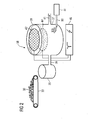
- FIG. 2 shows how in a bleaching device 38 of the same system 1, a raw material 30, in particular pulp, is conveyed as a third type of process material via a conveyor belt 33 in a fiber trough 35.
- the raw material 30 is mixed with water and pumped via a pipeline 36 into a bleaching trough 37.
- a first electrode 43 'and a second electrode 44' are each designed as a circular-area grid electrode.
- the first electrode 43 ' is arranged in the gas space of the pulp fiber suspension 39 filled in the bleaching trough 37.
- the second electrode 44 ' is arranged inside the bleaching trough 37 and is thus completely covered by the pulp fiber suspension 39.
- a large-area cold plasma is generated by means of the high-voltage pulse generator 46.
- the radical OH in the suspension 39 is preferably, O, O 3 produced. These radicals trigger a bleaching chemical reaction.
- the high voltage pulse generator 46 is operated to generate high voltage pulses having a duration of typically 1 ⁇ s between the electrodes 43 'and 44'. A voltage necessary for the generation of radicals and ozone in the pulp fiber suspension is about 100 kV. The high voltage pulses are superimposed on the DC voltage to form a total amplitude of a few 10 kV to over 100 kV.
- the radicals are generated in situ. Thus, large total amounts of radicals can be introduced into the suspension 39.
- the radicals are also very finely distributed in the suspension produced, so that the hitherto necessary effort for mixing chemicals with the suspension can be reduced.
- an oxygen-argon mixture in the bleaching trough 37 via a gas line 80, which has been processed in a gas distributor 81, to be initiated.
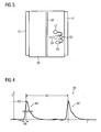
- FIG. 3 shows a sectional view of - to FIG. 2 alternative - bleaching vessel.
- a high voltage electrode 50 is arranged in the middle of the bleaching vessel.
- the outer jacket of the bleaching vessel is prepared as a counterelectrode 51.
- a pulp fiber suspension 39 is prepared between the electrodes 50 and 51.
- Radicals are generated in streamers by high-energy electrons colliding with and dissociating or exciting molecules. Upon dissociation, radicals 59 are immediately released, while upon excitation by a subsequent radiant transition, UV light is generated. This generated UV light in turn reacts with water molecules and dissociates them.
- a first pulse 66 and a second pulse 67 each having a pulse width 62, have a spacing of one pulse repetition time 63.
- the abscissa shows the time in ms and the ordinate the voltage in kV. The units are chosen arbitrarily.
- a level of some 10 kV of the DC voltage coincides with the abscissa shown.
- the illustrated pulse voltage is thus superimposed on the DC voltage.
- the pulses 66 and 67 have a pulse width 62 of less than 1 microseconds, wherein the individual pulses 66, 67 have a high rising edge with a rise time 64 and a Wen.iger steeply falling edge.
- the pulse repetition time 63 is typically between 10 ⁇ s and 100 ms.
- the individual pulses 66, 67 have such a total amplitude that a predefined energy density is achieved beyond the predetermined direct voltage.
- the pulse rise time 64 is short compared to the pulse fall time.
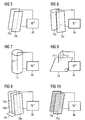
- FIG. 5 to FIG. 10 show examples of other electrode systems for generating corona discharges in preferably aqueous media.
- a plate-and-plate arrangement of a first plate 70a as an electrode and a second plate 70b as an electrode is illustrated.
- the first plate 70a and the second plate 70b are arranged parallel to each other.
- the first plate 70a forms the high voltage electrode and is connected to the high voltage pulse generator 46 via a high voltage cable.
- the second plate 70b forms the counter electrode and is connected as a grounded electrode to the high voltage pulse generator 46 in connection.
- FIG. 6 A corresponding arrangement with specially flat plate electrodes is in FIG. 6 shown. Again there are two solid plate electrodes 70a and 70c at a fixed distance with a high voltage electrode 71 in the middle.
- the high voltage electrode 71 is made of a solid wire and connected to the high voltage output of the high voltage pulse generator 46.
- the grounded plates 70a, 70c are also in communication with the high voltage pulse generator.
- FIG. 7 shows a wire-tube arrangement as an electrode system.
- a high-voltage electrode 71 projects centrally into a cylindrical electrode 72.
- the high voltage electrode 71 is made as a solid wire and connected to the high voltage pulse generator 46.
- the cylindrical electrode 72 which is preferably configured as a wire mesh, is grounded and communicates with the high voltage pulse generator 46.
- FIG. 8 shows a tip-plate assembly as an electrode system.
- three tips 73 are connected to the high voltage pulse generator 46 via a high voltage line.
- the tips 73 are perpendicular to a grounded one Plate electrode 74 is arranged.
- the distance of the tip electrodes 73 to the plate electrode 74 is adjustable and thus can be adapted for different process conditions.
- FIG. 9 shows an electrode system assembly comprising 3 plates 70a, 70d and 70e.
- the first plate 70a which is connected as a high-voltage electrode to the high-voltage pulse generator 46, is arranged centrally between two solid plates 70d and 70e.
- the plates 70d and 70e are connected via a plate connector 70f. Since the plate 70d as a grounded counter electrode is in communication with the high voltage pulse generator 46, the plate 70e above the plate connector 70f also functions as a grounded counter electrode.
- FIG. 10 shows an electrode system as a grid-grid arrangement. Analogous to FIG. 5 Here, a first grid 75a and a second grid 75b are parallel to each other.
- the first grid 75a forms the high voltage electrode and is connected to the high voltage pulse generator 46.
- the second grid 75b forms the grounded counter electrode and communicates with the high voltage pulse generator 46.
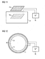
- a hybrid discharge wherein an electrode 76a is located entirely outside a pulp 39 to be bleached and a second electrode 76b is wholly or partially immersed in the pulp 39, is provided with the arrangement in FIG. 11 generated.
- the electrode 76a is implemented as a grid electrode and forms the high voltage electrode which is in communication with the high voltage pulse generator 46.
- the grounded Counter electrode 76b is implemented as a grid electrode and communicates with the high voltage pulse generator 46.
- a bleaching tub is shown with a vessel wall 77 in a plan view.
- a plate or grid arrangement with curved surfaces for adaptation to the vessel walls or use of the vessel walls is used as the electrode.
- a multiple wire electrode 79 is arranged as a concentric electrode following the course of the vessel wall 77 and communicates with the high voltage pulse generator 46. It faces two counterelectrodes: on the one hand the vessel wall 77 and on the other hand a plate electrode 78.
- the high voltage electrode 79 is arranged without contact between the vessel wall 77 and the plate electrode 78.
- the vessel wall 77 and the plate electrode 78 are electrically connected to each other and thus form the grounded counter electrodes, which are in communication with the high voltage pulse generator 46.
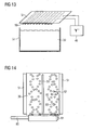
- a high-voltage electrode 50 comprises a plurality of electrically connected rod electrodes and is arranged in the near-surface gas space of the pulp 39 such that their rods are parallel to the surface.
- a grounded counter electrode 51 is designed as a solid plate and arranged in distributed over the entire surface equidistant distances to the high voltage electrode 50.
- FIG. 14 shows a pulsed corona discharge system in an aqueous solution or pulp 39.
- the electrode system is analogous to FIG. 3 formed as a coaxial wire tube electrode system.
- the high voltage electrode 50 is arranged coaxially with the counter electrode 51 forming the vessel wall.
- the finest gas bubbles are introduced into the discharge area via a gas line 80 by means of a gas distributor 81.
- the gas bubbles 82 and 83 are preferably formed to FIG. 3 mentioned streamer. Owing to the streamer discharges, oxidants 57 are formed. Thus, certain radicals are generated in the suspension.
Landscapes
- Engineering & Computer Science (AREA)
- Life Sciences & Earth Sciences (AREA)
- Wood Science & Technology (AREA)
- Mechanical Engineering (AREA)
- Paper (AREA)
- Chemical Or Physical Treatment Of Fibers (AREA)
Abstract
Description
Die Erfindung betrifft ein Verfahren zur Behandlung eines Prozessgutes bei der Herstellung von Papier, Karton oder Pappe, wobei ein, vorzugsweise nicht thermisches, großflächiges Plasma oder eine Gasentladung, insbesondere eine Koronaentladung, unter mindestens Atmosphärendruck appliziert wird und bei der Plasmaerzeugung und/oder bei der Gasentladung entstehende Radikale auf das Prozessgut einwirken.The invention relates to a process for the treatment of a process material in the production of paper, cardboard or cardboard, wherein a, preferably non-thermal, large-area plasma or a gas discharge, in particular a corona discharge, is applied under at least atmospheric pressure and in the plasma generation and / or in the Gas discharge resulting radicals act on the process material.
Heute übliche Verfahren der Behandlung und/oder Veredelung von Papier oder Papieroberflächen sind beispielsweise,
- Kalandrieren,
- Oberflächenbehandlung mit einer Leim- oder Filmpresse,
- Streichen von Papier und/oder Karton mit verschiedenen Verfahren und Materialien,
- Beschichtung von Papier im Extruderverfahren,
- Kaschierung mit anderen Materialien (z.B. Aluminiumfolie),
- Verklebung von Papier und Karton,
- Tränken von Papier,
- Bleichen.
- calendering,
- Surface treatment with a glue or film press,
- Painting paper and / or board with different processes and materials,
- Coating of paper in the extruder process,
- Lamination with other materials (eg aluminum foil),
- Bonding of paper and cardboard,
- Watering paper,
- Bleaching.
Eine Veredelung erfolgt entweder integriert in eine Papier-/Kartonmaschine oder auf einer separaten Anlage. Üblicherweise erfolgt eine Veredelung in mehreren aufeinander folgenden Verfahrensschritten. Folgende Qualitätseigenschaften werden durch die Veredelung positiv beeinflusst:
- Optische Eigenschaften, wie Glätte, Glanz, Weiße, Gleichmäßigkeit und Kontrast eines später durchgeführten Druckergebnisses,
- Verbesserung der Bedruckbarkeit für moderne Druckverfahren,
- Erhöhung der Papierfestigkeit und der Rupffestigkeit,
- Dimensionsstabilität des Papiers, Unempfindlichkeit gegen Feuchte,
- Erhaltung der Recyclingfähigkeit des Papiers.
- Optical properties, such as smoothness, gloss, whiteness, uniformity and contrast of a later printed result,
- Improvement of printability for modern printing processes,
- Increase paper strength and pick resistance
- Dimensional stability of the paper, insensitivity to moisture,
- Preservation of the recyclability of the paper.
Eine Mehrzahl dieser genannten Behandlungsverfahren beruht auf einer Behandlung mit chemischen Stoffen. Insbesondere beim Bleichen von Papier bzw. dessen Ausgangsstoffen werden im hohen Maße Bleichchemikalien eingesetzt. Typische Bleichchemikalien sind Chlor, Chlordioxid, schweflige Säuren, Extraktion mit Natronlauge, Sauerstoff, Wasserstoffperoxid und Ozon. Abhängig von der verwendeten Methode sind alkalische oder saure Umgebungsbedingungen gefordert. Moderne Bleichverfahren nutzen häufig verschiedene Bleichstufen, in denen verschiedene Bleichchemikalien zum Einsatz kommen, wobei jede Bleichstufe typischerweise aus einer Mischeinheit und einem nachfolgenden Reaktionsturm besteht. Bei diesen Verfahren müssen die zum Teil hochgiftigen (Chlordioxid) oder stark ätzenden Säuren, Laugen oder Reagenzien in großer Menge transportiert, gelagert, und nach Ablauf des Prozesses auch wieder aufgearbeitet bzw. entsorgt werden.A majority of these treatment methods are based on treatment with chemical substances. In particular, in the bleaching of paper or its starting materials bleaching chemicals are used to a high degree. Typical bleaching chemicals are chlorine, chlorine dioxide, sulphurous acids, extraction with caustic soda, oxygen, hydrogen peroxide and ozone. Depending on the method used, alkaline or acidic ambient conditions are required. Modern bleaching processes often make use of various bleaching stages in which various bleaching chemicals are used, each bleaching stage typically consisting of a mixing unit and a subsequent reaction tower. In these processes, the sometimes highly toxic (chlorine dioxide) or highly corrosive acids, alkalis or reagents must be transported in large quantities, stored, and after completion of the process also reprocessed or disposed of.
Aus "
Bisher beschränkt sich die Anwendung jedoch auf Methoden zur Reinigung von Abgasen, siehe "
Aus
Aus
Die Aufgabe wird dadurch gelöst, dass für wenigstens zwei verschiedene Arten von Prozessgütern oder an wenigstens zwei unterschiedlichen Prozessstufen Radikale unterschiedlicher Art oder Zusammensetzung verwendet werden. Durch die simultane Erzeugung einer Reihe von unterschiedlich oxidierenden und funktionalisierenden Radikalen (O, OH,' HO2, HO2 -, O2, O3, ... ) und die Anwendung solcher verschiedener Radikalen auf das Prozessgut an unterschiedlichen Stellen im Prozess kann mit Vorteil bei der Papierherstellung das Zugeben von Feststoff-und/oder Flüssig-Chemikalien reduziert werden.The object is achieved by using radicals of different types or compositions for at least two different types of process goods or at at least two different process stages. By the simultaneous generation of a number of differently oxidizing and functionalizing radicals (O, OH, HO 2 , HO 2 - , O 2 , O 3 , ...) and the application of such various radicals to the process material at different points in the process can be beneficial in papermaking, the addition of solid and / or liquid chemicals can be reduced.
Bevorzugt ist, dass die Prozessgüter aus folgenden Ausgangsmaterialien und/oder Zwischenprodukten ausgewählt sind:
- Trockene Fasern,
- unverwobene Faserstoffe,
- voluminöse/r Pulpe oder Faser-Suspension oder Faserbrei,
- aufgelaufene/r und/oder flächig verteilte/r Pulpe oder Faser-Suspension oder Faserbrei,
- sich bildendes oder gebildetes, noch ungepresstes Blatt, mit Restfeuchte.
- Dry fibers,
- unwoven fibrous materials,
- voluminous pulp or fiber suspension or pulp,
- accumulated and / or areal pulp or fiber suspension or pulp,
- forming or formed, still unpressed sheet, with residual moisture.
Die zuvor genannten Prozessgüter treten, z.B. als Ausgangsprodukte und/oder Zwischenprodukte, an unterschiedlichen Prozessstufen innerhalb des Papierherstellungsprozesses auf.The aforementioned process items occur, e.g. as starting materials and / or intermediates, at different process stages within the papermaking process.
Besonders zweckmäßig ist, falls die Prozessstufen aus folgenden Stufen ausgewählt sind:
- Kochen,
- Mahlen,
- Bleichen,
- Sieben,
- Pressen.
- Cook,
- Grind,
- Bleaching,
- Seven,
- Press.
Mit weiterem Vorteil werden als Radikale Ozon, Wasserstoffperoxid, Hydroxyl-Radikale, HO2 und/oder HO2 - erzeugt. Radikale werden vorzugsweise in Gasentladungen dadurch erzeugt, dass energiereiche Elektronen mit Molekühlen zusammenstoßen und diese dadurch dissoziieren oder anregen. Bei der Dissoziation werden unmittelbar Radikale freigesetzt, während bei der Anregung durch anschließende strahlende Übergänge UV-Licht erzeugt wird, welches wiederum mit Luft- und/oder Wassermolekühlen reagiert und diese dissoziiert.With further advantage as radicals are produced ozone, hydrogen peroxide, hydroxyl radicals, HO 2 and / or HO 2 - . Radicals are preferably generated in gas discharges by high energy electrons colliding with and thereby dissociating or exciting molecules. In the dissociation, radicals are released immediately, while in the excitation by subsequent radiant transitions UV light is generated, which in turn reacts with air and / or water molecules and dissociates them.
Nach einer ersten bevorzugten Ausführungsform wird beim Bleichen des Prozessgutes das Plasma oder die Gasentladung derart appliziert, dass als Radikale vermehrt Ozon und/oder Wasserstoffperoxid gebildet werden.According to a first preferred embodiment, the bleaching of the process material, the plasma or the gas discharge is applied in such a way that as radicals increasingly ozone and / or hydrogen peroxide are formed.
Nach einer zweiten vorzugsweisen Ausführungsform wird beim Sieben und/oder bei flächig verteiltem Prozessgut oder in sich bildenden oder gebildeten, noch ungepressten Blatt das Plasma oder die Gasentladung derart appliziert, dass als Radikale vermehrt OH, HO2 und/oder HO2 - gebildet wird.According to a second preferred embodiment, the plasma or the gas discharge is applied in such a way that the radicals OH, HO 2 and / or HO 2 - are formed during sieving and / or in distributed process material or in forming or formed, still unpressed sheet.
Vorteilhafterweise wird eine Erzeugungsrate der Radikale und/oder die Zusammensetzung der erzeugten Radikale durch eine Beeinflussung einer Amplitude, einer Impulsdauer und/oder einer Impulswiederholrate von Hochspannungsimpulsen gesteuert und/oder geregelt. Da die Erzeugungsrate der Radikale von einem elektrischen Prozess erzeugt und damit in Echtzeit sehr gut steuerbar ist, ist ein solches Verfahren sehr wirtschaftlich und kann innerhalb kürzester Zeit für unterschiedliche Behandlungsergebnisse nachgeregelt werden, beispielsweise durch einen lernfähigen Algorithmus.Advantageously, a generation rate of the radicals and / or the composition of the generated radicals is controlled and / or regulated by influencing an amplitude, a pulse duration and / or a pulse repetition rate of high-voltage pulses. Since the generation rate of the radicals generated by an electrical process and thus very well controlled in real time, such a method is very economical and can be readjusted within a very short time for different treatment outcomes, for example by a learning algorithm.
Eine andere bevorzugte Ausführungsform der Erfindung ist, dass zur Steuerung und/oder Regelung der Erzeugungsrate und/oder der Art der erzeugten Radikale eine Konzentration der erzeugten Radikale gemessen wird.Another preferred embodiment of the invention is that for controlling and / or regulating the rate of production and / or the type of radicals generated a concentration of the generated radicals is measured.
Im Besonderen ist es im Hinblick auf eine Behandlung an unterschiedlichen Prozessstufen von Vorteil, dass zur Steuerung und/oder Regelung der Erzeugungsrate oder der Zusammensetzung der erzeugten Radikale für verschiedene Arten von Prozessgütern jeweils eine andere Eigenschaft des Prozessgutes, vorzugsweise eine Qualitätseigenschaft, insbesondere dessen Opazität, Glanz, Weiße, Fluoreszenz oder Farbpunkt, gemessen wird.In particular, with regard to a treatment at different process stages, it is advantageous for the control and / or regulation of the generation rate or the composition of the generated radicals for different types of process goods to have in each case a different property of the process material, preferably a quality property, in particular its opacity. Gloss, whiteness, fluorescence or color point, is measured.
Ebenfalls zweckmäßig ist es, dass die Konzentration bzw. die Eigenschaft "online" gemessen wird. Im Hinblick auf eine eingesetzte Automatisierungslösung für das Verfahren ist es vom besonderen Vorteil, dass ein, die Qualitätseigenschaften beschreibender Messwert, quasi zeitgleich ausgewertet und beispielsweise durch ein Beeinflussen der Erzeugungsrate auf ihn reagiert werden kann.It is also appropriate that the concentration or the property "online" is measured. With regard to an automation solution used for the method, it is of particular advantage that a measured value describing the quality characteristics can be evaluated virtually at the same time and reacted to it, for example, by influencing the generation rate.
Um die Erzeugungsrate der Radikale zu kontrollieren, kann zur Regelung die Amplitude der Hochspannungsimpulse bei konstanter Wiederholrate oder/und die Wiederholrate der Hochspannungsimpulse bei konstanter Amplitude verändert werden.In order to control the generation rate of the radicals, the amplitude of the high voltage pulses at a constant repetition rate and / or the repetition rate of the high voltage pulses at a constant amplitude can be changed for regulation.
Von besonderem Vorteil ist es, falls das Plasma und/oder die Gasentladung zwischen Elektroden erzeugt werden.It is particularly advantageous if the plasma and / or the gas discharge are generated between electrodes.
Eine weitere Steigerung des Behandlungsergebnisses wird dadurch erreicht, dass das Prozessgut im plasmabeaufschlagten Bereich mit Sauerstoff angereichert wird.A further increase in the treatment result is achieved by enriching the process material with oxygen in the plasma-exposed area.
Nach besonders vorteilhafter Weise werden zur Erzeugung des Plasmas bzw. der Gasentladung zwischen den Elektroden Hochspannungsimpulse mit einer Dauer von weniger als 10 µs erzeugt. Die Verwendung von derartig kurzen Hochspannungs-Einzelimpulsen hat sich als besonders vorteilhaft gezeigt, wogegen die Verwendung von Radiofrequenz- (RF) oder Mikrowellenimpulsen oder von Hochspannungs-Einzelimpulsen mit mehr als 10 µs Dauer, weit weniger effizient ist.According to a particularly advantageous manner, high-voltage pulses having a duration of less than 10 μs are generated between the electrodes to generate the plasma or the gas discharge. The use of such short high voltage single pulses has been found to be particularly advantageous, whereas the use of radio frequency (RF) or microwave pulses or of high voltage single pulses of more than 10 μs in duration, is far less efficient.
Vorzugsweise für Prozessgüter mit einer hohen Leitfähigkeit ist es zweckmäßig, dass Hochspannungsimpulse mit einer Dauer von weniger als 3 µs, vorzugsweise von weniger als 1 µs, vorzugsweise von weniger als 500 ns, angewendet werden. Hochspannungsimpulse mit einer Dauer von mehr als 10 µs, wie bereits erwähnt, oder Hochspannungsimpulse, welche eine nicht steil genug ansteigende Impulsflanke aufweisen, haben hier den Nachteil, dass ihre Energie in sehr leitfähigen Materialien als "ohmscher-Anteil" zunichte gemacht wird.Preferably, for process products having a high conductivity, it is expedient that high-voltage pulses having a duration of less than 3 μs, preferably less than 1 μs, preferably less than 500 ns, are used. High-voltage pulses with a duration of more than 10 μs, as already mentioned, or high-voltage pulses which have a pulse edge which does not rise steeply enough, have the disadvantage here that their energy is nullified in highly conductive materials as an "ohmic component".
Somit ist es weiterhin zweckmäßig, dass bei einer Pulpe, einer Faser-Suspension oder einem Faserbrei als Prozessgut, vorzugsweise beim Bleichen, eine Hochspannungs-Impulsdauer von weniger als 100 ns verwendet wird.Thus, it is also expedient that in the case of a pulp, a fiber suspension or a pulp as process material, preferably when bleaching, a high-voltage pulse duration of less than 100 ns is used.
Weiterhin ist es zweckmäßig, dass bei flächig verteiltem Prozessgut oder in sich bildenden oder gebildeten, noch ungepressten Blatt, insbesondere beim Sieben, eine Hochspannungs-Impulsdauer von 100 ns bis 1 µs verwendet wird.Furthermore, it is expedient that in the case of distributed process material or in forming or formed, still unpressed sheet, in particular when screening, a high-voltage pulse duration of 100 ns to 1 microseconds is used.
Um auf vorteilhafte Weise eine weitere Steigerung des Behandlungsergebnisses zu erzielen, wird bei flächig verteiltem Prozessgut oder in sich bildenden oder gebildeten, noch ungepressten Blatt, insbesondere beim Sieben, der mit Plasma beaufschlagte Bereich von einer mit Wasserdampf angereicherten Atmosphäre umgeben.In order to achieve a further increase in the treatment result in an advantageous manner, the region exposed to plasma is surrounded by an atmosphere enriched with water vapor in process material which is distributed over a wide area or in which the sheet is still undpressed, in particular during sieving.
Darüber hinaus ist es bevorzugt, dass bei flächig verteiltem Prozessgut oder in sich bildenden oder gebildeten, noch ungepressten Blatt, insbesondere beim Sieben, eine Amplitude entsprechend mindestens dem zweifachen Wert, vorzugsweise mit mindestens dem dreifachen Wert einer Korona-Einsatzspannung, an die Elektroden angelegt wird.In addition, it is preferred that in the case of flatly distributed process material or in forming or formed, still unpressed sheet, in particular during screening, an amplitude corresponding to at least twice, preferably with at least three times the value of a corona threshold voltage applied to the electrodes ,
Zweckmäßig ist ferner, dass zur Erzeugung des Plasmas bzw. der Korona- Entladung eine Gleichspannungs-Korona-Entladung erzeugt wird und der Gleichspannungs-Korona-Entladung die Hochspannungsimpulse überlagert werden. Die Überlagerung der Hochspannungsimpulse mit einer Gleichspannung hat den besonderen Vorteil, dass die energiereichen Hochspannungsimpulse bereits von einem sehr hohen Energieniveau starten können.It is also expedient that a DC corona discharge is generated to generate the plasma or the corona discharge and the DC voltage corona discharge, the high voltage pulses are superimposed. The superimposition of the high-voltage pulses with a DC voltage has the particular advantage that the high-energy high-voltage pulses can already start from a very high energy level.
Je nach Lebensdauer oder Art oder Zusammensetzung der erzeugten Radikale ist es zweckmäßig, dass eine Impulswiederholrate zwischen 10Hz und 5kHz, insbesondere aus dem Bereich von 10Hz bis 10kHz, verwendet wird.Depending on the lifetime or type or composition of the generated radicals, it is expedient that a pulse repetition rate between 10 Hz and 5 kHz, in particular from the range of 10 Hz to 10 kHz, is used.
Weiterhin vorzugsweise wird die Leistungseinkopplung elektrischer Energie in das Plasma vorwiegend über die Regelung von Amplitude, Impulsdauer und Impulswiederholrate der überlagerten Hochspannungsimpulse gesteuert.Furthermore, the power coupling of electrical energy into the plasma is preferably controlled predominantly via the regulation of amplitude, pulse duration and pulse repetition rate of the superposed high-voltage pulses.
Zweckmäßig ist auch, dass ein homogenes, großvolumiges Plasma mit hoher Leistungsdichte erzeugt wird, ohne dass es zu Plasmaeinschnürungen oder Durchschlägen kommt. Durch die Erzeugung eines "stabilen" Plasmas kann die Erzeugungsrate hoch und konstant gehalten werden, kommt es hingegen zu Plasmaeinschnürungen oder Durchschlägen, so sinkt die Erzeugungsrate wieder.It is also expedient that a homogeneous, large-volume plasma with high power density is produced, without resulting in plasma constrictions or punctures. By generating a "stable" plasma, the production rate can be kept high and constant, but if plasma constrictions or breakdowns occur, the production rate decreases again.
Zweckmäßig ist es, dass eine DC-Spannung von solcher Höhe eingesetzt wird, dass im Plasma nur in Verbindung mit überlagerten Hochspannungsimpulsen eine stabile DC-Korona-Entladung gebildet wird.It is expedient that a DC voltage of such height is used that a stable DC corona discharge is formed in the plasma only in conjunction with superposed high-voltage pulses.
Mit Vorteil liegt die eingesetzte DC-Spannung unter der Spannung für einen stabilen Betrieb ohne Hochspannungs-Impulsüberlagerung.Advantageously, the DC voltage used is below the voltage for stable operation without high voltage pulse superposition.
Des Weiteren ist es zweckmäßig, dass die eingesetzte Gesamtamplitude (DC-Spannung + Impulsamplitude) über der statischen Durchbruchspannung der Elektrodenanordnung liegt.Furthermore, it is expedient that the total amplitude used (DC voltage + pulse amplitude) is above the static breakdown voltage of the electrode arrangement.
Zweckmäßig ist, falls die eingesetzte Gesamtamplitude dem zwei- bis fünffachen der statischen Durchbruchspannung der Elektrodenanordnung entspricht.It is expedient if the total amplitude used corresponds to two to five times the static breakdown voltage of the electrode arrangement.
Vorzugsweise wird die Spannung so gewählt, dass die Amplitude der Hochspannungsimpulse zwischen 10 % und 1000 % der eingesetzten DC-Spannung beträgt.Preferably, the voltage is selected so that the amplitude of the high voltage pulses is between 10% and 1000% of the DC voltage used.
In einer bevorzugten Ausgestaltung wird das Plasma in einem Abstand von kleiner 20 cm, vorzugsweise kleiner 10 cm, vorzugsweise kleiner 5 cm von dem Prozessgut erzeugt.In a preferred embodiment, the plasma is generated at a distance of less than 20 cm, preferably less than 10 cm, preferably less than 5 cm from the process material.
Bevorzugte, jedoch keinesfalls einschränkende Ausführungsbeispiele der Erfindung werden nunmehr anhand der Zeichnung näher erläutert. Zur Verdeutlichung ist die Zeichnung nicht maßstäblich ausgeführt, und gewisse Merkmale sind nur schematisiert dargestellt. Einander entsprechende Teile sind in den Figuren mit denselben Bezugszeichen versehen. Im Einzelnen zeigt die
- FIG 1
- eine schematische Darstellung einer Papierherstel- lungsanlage mit einer Siebvorrichtung, einer Pressen Vorrichtung und einer Veredelungs- und/oder Trocken- anlage,
- FIG 2
- eine Bleichvorrichtung,
- FIG 3
- eine Darstellung (Schnitt) einer Anordnung zur Erzeu- gung von Radikalen in Koronaplasmen in Pulpe oder Luft: Parallelplatten- oder Rohranordnung mit Draht, dem eine gepulste Hochspannung überlagert wird,
- FIG 4
- eine Prinzipdarstellung von Impulsen zur Erzeugung von Radikalen in Koronaentladungen in Luft oder wässrigen Medien bei Einsatz kurzer (typisch < 1 µs) Hochspan- nungsimpulse mit hoher Impulswiederholrate,
- FIG 5 bis FIG 10
- Elektrodenanordnungen und Elektrodensysteme zur Erzeugung von Koronaentladungen: Platte-Platte-, Platte-Draht-Platte-, koaxiale Draht-Rohr-, Spitze- Platte-, Mehrfachspitzen-Platte-, Gitter-Platte (Rohr)-, Gitter-Gitter-Anordnungen,
- FIG 11
- eine hybride Entladung, wobei sich eine Elektrode vollständig oberhalb des Mediums auf dem Sieb befin- det, wogegen die zweite Elektrode durch das Sieb selbst gebildet wird,
- FIG 12
- eine Platten- oder Gitteranordnungen mit gekrümmten Oberflächen zur Anpassung an Gefäßwände bzw. Nutzung derselben als Elektrode, konzentrische Elektroden in Rohrform zur Nutzung der vorhandenen Verrohrung oder Türme für die Pulpe als Reaktorgefäß,
- FIG 13
- eine gepulste Entladung im oberflächennahen Gasraum über Stoffauflauf auf dem Sieb mit Vielfachdraht- Platte-Anordnung, und
- FIG 14
- ein gepulstes Koronaentladungssystem mit koaxialem Draht-Rohr, mit eingeperlten, feinstverteilten Gasbla- sen, so dass im Entladungsbereich feinste Gasperlen vorhanden sind und eine Streamerbildung vorwiegend in den Gasblasen abläuft.
- FIG. 1
- a schematic representation of a papermaking plant with a screening device, a pressing device and a finishing and / or drying plant,
- FIG. 2
- a bleaching device,
- FIG. 3
- a representation (section) of an arrangement for the generation of radicals in corona plasmas in pulp or air: parallel plate or tube arrangement with wire, which is overlaid with a pulsed high voltage,
- FIG. 4
- a schematic representation of pulses for generating radicals in corona discharges in air or aqueous media with use of short (typically <1 μs) high voltage pulses with high pulse repetition rate,
- FIG. 5 to FIG. 10
- Electrode arrays and electrode systems for generating corona discharges: plate-plate, plate-wire-plate, coaxial-wire-tube, tip-plate, multi-tip-plate, grid-plate (tube), grid-grid-arrangements,
- FIG. 11
- a hybrid discharge, with one electrode completely above the medium on the screen, while the second electrode is formed by the screen itself,
- FIG. 12
- a plate or grid arrangement with curved surfaces for adaptation to vessel walls or use thereof as an electrode, concentric electrodes in tube form to use the existing piping or towers for the pulp as a reactor vessel,
- FIG. 13
- a pulsed discharge in the near-surface gas space over headbox on the wire with multi-wire plate arrangement, and
- FIG. 14
- a pulsed corona discharge system with coaxial wire tube, with beaded, very finely divided gas bubbles, so that in the discharge area finest gas bubbles are present and a streamer formation takes place mainly in the gas bubbles.
Altpapier und in der Regel auch Zellstoff erreichen eine Papierfabrik in trockener Form, während Holzstoff normalerweise im gleichen Werk erzeugt und als Faser-/Wasser-Mischung, also einer Suspension aus unverwobenen Faserstoffen, in die Stoffzentrale 3 gepumpt werden. Altpapier und Zellstoff 30 (siehe
Der Stoffauflauf 7 der Papierherstellungsanlage 1 verteilt die Faserstoff-Suspension gleichmäßig über die gesamte Siebbreite. Am Ende der Siebvorrichtung 9 enthält die Papierbahn 27 noch immer ca. 80 % Wasser.The headbox 7 of the papermaking plant 1 distributes the pulp suspension uniformly over the entire wire width. At the end of the
Ein weiterer Entwässerungsprozess erfolgt durch mechanischen Druck in der Pressenvorrichtung 11. Dabei wird die Papierbahn 27 mittels eines saugfähigen endlosen Filztuches zwischen Walzen aus Stahl, Granit oder Hartgummi hindurchgeführt und dadurch entwässert. Das durch den Saugkammerbereich 24 aufgenommene Siebwasser 23 wird zu einem Teil zu einem Sortierer 5 zugeführt und zu einem anderen Teil zu einem Stofffänger 17 zurückgeführt. An die Pressenvorrichtung 11 schließt sich eine Trocknungsanlage 13 an. Das verbleibende Restwasser wird in der Trocknungsanlage 13 verdampft. Slalomartig durchläuft die Papierbahn 27 mehrere dampfbeheizte Trockenzylinder. Am Ende hat das Papier 27 eine Restfeuchte von wenigen Prozent. Der in der Trocknungsanlage 13 entstandene Wasserdampf wird abgesaugt und in eine nicht dargestellte Wärmerückgewinnungsanlage geführt.Another dewatering process is carried out by mechanical pressure in the
Für eine Behandlung der Fasersuspension 39 als erste Art von Prozessgut sind nach dem erfindungsgemäßen Verfahren zwischen dem Stoffauflauf 7 und dem Anfangsbereich der Siebvorrichtung 9 eine erste Elektrode 43 unter der Siebvorrichtung 9 und eine zweite Elektrode 44 über der Siebvorrichtung 9 angeordnet. Die Elektroden 43 und 44 sind derart angeordnet, dass die flächig verteilte Faser-Suspension 39 zwischen ihnen verläuft. Damit zur Behandlung der Faser-Suspension 39 ein großflächiges Plasma unter Atmosphärendruck in unmittelbarer Nähe zu der Faser-Suspension 39 erzeugt werden kann, sind die Elektroden 43 und 44 mit einem Hochspannungsimpulsgenerator 46 verbunden. Mit Hilfe dieses Hochspannungsimpulsgenerators 46 wird zwischen den Elektroden 43 und 44 ein großvolumiges Plasma mit einem großen Querschnitt und mit hoher Leistungsdichte hergestellt. Hierbei ist eine Plasmadichte homogen über den Behandlungsbereich, welcher durch die Elektroden 43 und 44 abgedeckt wird, verteilt. Erfindungsgemäß wird dieses großvolumige Plasma mit hoher Leistungsdichte dadurch erzeugt, dass einer DC-Korona-Entladung intensive, kurz andauernde Hochspannungsimpulse mit einer hohen Impulswiederholrate von typisch 1 kHz überlagert werden. Bei dieser Betriebsweise wird ein äußerst homogenes, großvolumiges Plasma mit einer hohen Leistungsdichte erzeugt, ohne dass es zu den bei DC-Korona-Entladungen bekannten Plasmaeinschnürungen kommt.For a treatment of the
Um die Behandlungswirkung, welche das kalte großflächige Plasma auf die Faser-Suspension ausübt, zu unterstützen, kann mittels eines Gasverteilers 81 über eine Gasleitung 80 Sauerstoff mit Argon als Trägergas in den Behandlungsraum zwischen die Elektroden 43 und 44 eingeleitet werden. Mit Hilfe des Sauerstoff-Argon-Gemisches werden besonders vorteilhaft Hydroxyl-Radikale erzeugt. Hydroxyl-Radikale sind besonders aggressiv und oxidierend, dadurch wird an dem nur wenige Sekunden im Behandlungsbereich zwischen den Elektroden 43 und 44 verweilenden Faser-Suspension eine bleichende Wirkung erzielt.In order to support the treatment effect which the cold large-area plasma exerts on the fiber suspension, oxygen with argon as the carrier gas can be introduced into the treatment space between the
Analog zu dem zuvor beschriebenen wird mit einem Elektrodensystem 47, 48 in der Pressenvorrichtung 11 ein großflächiges Plasma zur Behandlung der Papierbahn 27 als zweite Art von Prozessgut erzeugt. Die erste Elektrode 47 in der Pressenvorrichtung 11 ist als eine halbrunde Gitterelektrode ausgeführt. Durch die halbrunde Ausgestaltung der Elektrode 47 kann sie dem Papierbahnverlauf über einer Transportrolle 12 folgen. Die zweite Elektrode 48 in der Pressenvorrichtung 11 ist als eine Plattenelektrode ausgestaltet und derart angeordnet, dass die Transportrolle 12 zwischen den Elektroden 47 und 48 geführt werden kann. Um auch hier die Radikalbildung im Plasma anzuregen, kann auch hier der Plasmabehandlungsbereich über den Gasverteiler 81 mit der Gasleitung 80 mit einem Sauerstoff-Argon-Gemisch angeströmt werden.Analogous to that described above, an
Der Pressvorgang verdichtet das Papiergefüge, eine Festigkeit erhöht sich und eine Oberflächengüte wird entscheidend beeinflusst. Durch die Behandlung des gepressten Papiers mit kaltem Plasma, insbesondere mit den erzeugten Radikalen, wird die molekulare Struktur der Papieroberfläche weiter verändert. Die Festigkeit des Papiers 27 wird erhöht und eine Bedruckbarkeit verbessert.The pressing process compacts the paper structure, a strength increases and a surface quality is decisively influenced. By treating the pressed paper with cold plasma, especially with the generated radicals, the molecular structure of the paper surface is further altered. The strength of the
Mit den vorbenannten Elektrodenanordnungen 43 und 44 sowie 47 und 48 ist es nach dem erfindungsgemäßen Verfahren möglich die Papierbahn 27 zwischen Streamer-Entladungen zu führen. Ein Streamer ist eine spezielle Form einer sich linear fortbewegenden Plasmawolke oder ein in der Entwicklung befindlicher Entladungskanal, der sich aufgrund der angeregten hohen externen Feldstärke ausbildet. Ein Aufbau solcher Streamer findet innerhalb weniger 10 ns statt und geht sehr schnell in einen thermischen Durchschlagskanal über. Vorbenannte Anordnungen der Elektrodensysteme, wobei sich die Papierbahn 27 zwischen den zur Streamer-Entladung benutzten Elektroden befindet, ist besonders vorteilhaft, da das Papier 27 dadurch teilweise als eine dielektrische Barriere fungiert, wodurch sich der Übergang vom Streamerdurchschlag verzögern oder unterdrücken lässt.With the above-mentioned
Durch eine direkte Behandlung der Zellstofffaser-Suspension 39 mit dem kalten Plasma werden in der Suspension 39 vorzugsweise die Radikale OH-, HOO-, O, O3 erzeugt. Diese Radikale lösen eine bleichende chemische Reaktion aus. Der Hochspannungsimpulsgenerator 46 wird derart betrieben, dass er Hochspannungsimpulse mit einer Dauer von typisch 1 µs zwischen den Elektroden 43' und 44' erzeugt. Eine für die Erzeugung von Radikalen und Ozon in der Zellstofffaser-Suspension notwendige Spannung liegt bei ca. 100 kV. Die Hochspannungsimpulse werden der DC-Spannung überlagert und bilden so eine Gesamtamplitude von einigen 10 kV bis über 100 kV. Durch die Behandlung der Zellstofffaser-Suspension 39 mit einer kalten elektrischen Entladung, also dem Plasma, werden die Radikale in-situ erzeugt. So können große Gesamtmengen von Radikalen in die Suspension 39 eingebracht werden. Die Radikale werden zudem feinst verteilt in der Suspension erzeugt, so dass auch der bisher nötige Aufwand zur Mischung von Chemikalien mit der Suspension reduziert werden kann., HOO - - by direct treatment of the
Für eine weitere Steigerung des Bleichprozesses kann in den Bleichtrog 37 über eine Gasleitung 80 ein Sauerstoff-Argon-Gemisch, welches in einem Gasverteiler 81 aufbereitet wurde, eingeleitet werden.For a further increase of the bleaching process, an oxygen-argon mixture, in the
In
Dabei haben die einzelnen Impulse 66,67 eine solche Gesamtamplitude, dass über die vorgegebene Gleichspannung hinaus eine vorgegebene Energiedichte erreicht wird. Wie erwähnt, ist die Pulsanstiegszeit 64 dabei kurz im Vergleich zur Pulsabfallzeit. Durch eine solche Art der Impulse wird erreicht, dass elektrische Durchschläge, die zu räumlichen und zeitlichen Störungen in der homogenen Plasmadichteverteilung führen würden, vermieden werden.In this case, the
Eine entsprechende Anordnung mit speziell ebenen Plattenelektroden ist in
Für alle aufgeführten Elektrodenanordnungen ist es im Hinblick auf eine Steigerung eines Behandlungsergebnisses oder eines Bleichprozesses vorteilhaft, dass eine Gasströmung senkrecht zu der Elektrodenanordnung erzeugt wird. Ebenso ist es zweckmäßig, dass eine Gasströmung parallel zu der Elektrodenanordnung erzeugt wirdWith regard to an increase in a treatment result or a bleaching process, it is advantageous for all listed electrode arrangements that a gas flow is generated perpendicular to the electrode arrangement. Likewise, it is expedient that a gas flow is generated parallel to the electrode arrangement
Eine hybride Entladung, wobei sich eine Elektrode 76a vollständig außerhalb einer zu bleichenden Pulpe 39 befindet und eine zweite Elektrode 76b ganz oder teilweise in der Pulpe 39 eingetaucht ist, wird mit der Anordnung in
In
Um gepulste Entladungen im oberflächennahen Gasraum über der Pulpe 39 zu erzeugen ist in
Claims (30)
- Method for treating a process material during the production of paper (27), board or cardboard, a preferably non-thermal large-area plasma or a gas discharge, in particular a corona discharge, being applied under at least atmospheric pressure and radicals (59) produced during the plasma production and/or during the gas discharge acting on the process material,
characterized in that, for at least two different types of process materials or in at least two different process stages, radicals (59) of different type or composition are used. - Method according to Claim 1,
characterized in that the process materials are chosen from the following starting materials and/or intermediate products:- dry fibres,- unwoven fibrous materials,- voluminous pulp or fibrous suspension or fibrous stock (39),- discharged and/or two-dimensionally distributed pulp or fibrous suspension or fibrous stock (39),- a forming or formed, as yet unpressed sheet having residual moisture. - Method according to Claim 1 or 2,
characterized in that the process stages are chosen from the following stages:- digestion,- refining,- bleaching,- screening,- pressing. - Method according to one of Claims 1 to 3,
characterized in that the radicals (59) produced are ozone (O3), hydrogen peroxide (H2O2), hydroxyl radicals (OH), HO2 and/or HO2 -. - Method according to one of Claims 1 to 4,
characterized in that, during the bleaching of the process material, the plasma or the gas discharge is applied in such a way that the radicals (59) formed are increasingly ozone (O3) and/or hydrogen peroxide (H2O2). - Method according to one of Claims 1 to 4,
characterized in that, during the screening and/or in the case of two-dimensionally distributed process material or in the forming or formed, as yet unpressed sheet, the plasma or the gas discharge is applied in such a way that the radicals (59) formed are increasingly OH, HO2 and/or HO2 -. - Method according to one of Claims 1 to 6,
characterized in that a production rate of the radicals (59) and/or the composition of the radicals (59) produced is controlled and/or regulated by influencing an amplitude (U), a pulse duration (62) and/or a pulse repetition rate (63) of high voltage pulses (66, 67). - Method according to Claim 7,
characterized in that, in order to control and/or regulate the production rate and/or the type of radicals (59) produced, a concentration of the radicals (59) produced is measured. - Method according to Claim 7 or 8,
characterized in that, in order to control and/or regulate the production rate or the composition of the radicals (59) produced for various types of process materials, in each case another property of the process material, preferably a quality property, in particular the opacity, gloss, whiteness, fluorescence or colour locus thereof, is measured. - Method according to either of Claims 8 and 9, characterized in that the concentration or the property is measured "online".
- Method according to one of Claims 7 to 10,
characterized in that, for the purpose of regulation, the amplitude (U) of the high voltage pulses (66, 67) is varied at constant repetition rate (63). - Method according to one of Claims 7 to 11,
characterized in that, for the purpose of regulation, the repetition rate (63) of the high voltage pulses (66, 67) is varied at constant amplitude (U). - Method according to one of Claims 1 to 12,
characterized in that the plasma or the gas discharge is produced between electrodes (43, 44). - Method according to one of Claims 1 to 13,
characterized in that the process material is enriched with oxygen in the region to which plasma is applied. - Method according to one of Claims 7 to 14,
characterized in that high voltage pulses (66, 67) with a duration (62) of less than 10 µs are produced between the electrodes (43, 44). - Method according to Claim 15,
characterized in that high voltage pulses (66, 67) with a pulse duration (62) of less than 3 µs, preferably of less than 1 µs, preferably of less than 500 ns, are applied. - Method according to Claim 15 or 16,
characterized in that, in the case of a pulp (39), a fibrous suspension or a fibrous stock as process material, preferably during bleaching, a high voltage pulse duration (62) of less than 100 ns is used. - Method according to one of Claims 13 to 15,
characterized in that, in the case of two-dimensionally distributed process material or in the forming or formed, as yet unpressed sheet, in particular during screening, a high voltage pulse duration (62) of 100 ns to 1 µs is used. - Method according to one of Claims 1 to 18,
characterized in that, in the case of two-dimensionally distributed process material or in the forming or formed, as yet unpressed sheet, in particular during screening, the region to which plasma is applied is surrounded by an atmosphere enriched with water vapour. - Method according to one of Claims 7 to 19,
characterized in that, in the case of two-dimensionally distributed process material or in the forming or formed, as yet unpressed sheet, in particular during screening, an amplitude (U) corresponding to at least twice the value, preferably at least three times the value, of a corona strike voltage is applied to the electrodes. - Method according to one of Claims 7 to 20,
characterized in that, in order to produce the plasma or the corona discharge, a DC corona discharge is produced and the high voltage pulses (66, 67) are superimposed on the DC corona discharge. - Method according to one of Claims 7 to 21,
characterized in that a pulse repetition rate (63) between 10 Hz and 5 kHz, in particular from the range from 10 Hz to 10 kHz, is used. - Method according to one of Claims 7 to 22,
characterized in that the power injection of electrical energy into the plasma is predominantly controlled via the regulation of amplitude (U), pulse duration (62) and pulse repetition rate (63) of the superimposed high voltage pulses. - Method according to one of Claims 1 to 23,
characterized in that a homogeneous, large-volume plasma with a high power density is produced without plasma pinching or breakdowns occurring. - Method according to one of Claims 1 to 24, characterized in that use is made of a DC voltage of such a level that, in the plasma in conjunction with superimposed high voltage pulses, a stable DC corona discharge is formed.
- Method according to one of Claims 7 to 25,
characterized in that the DC voltage used lies below that for stable operation without high voltage pulse superimposition. - Method according to one of Claims 13 to 26,
characterized in that the total amplitude used (DC voltage + pulse amplitude) lies above the static breakdown voltage of the electrode arrangement. - Method according to Claim 27,
characterized in that the total amplitude used corresponds to two to five times the static breakdown voltage of the electrode arrangement. - Method according to one of Claims 26 to 28,
characterized in that the amplitude (U) of the high voltage pulses is between 10% and 1000% of the DC voltage used. - Method according to one of Claims 1 to 29,
characterized in that the plasma is produced at a distance from the process material of less than 20 cm, preferably less than 10 cm, preferably less than 5 cm.
Applications Claiming Priority (3)
| Application Number | Priority Date | Filing Date | Title |
|---|---|---|---|
| DE102005028046 | 2005-06-16 | ||
| DE102005049231A DE102005049231A1 (en) | 2005-06-16 | 2005-10-14 | Process for the treatment of a process material in the production of paper, cardboard or cardboard |
| PCT/EP2006/063011 WO2006134064A1 (en) | 2005-06-16 | 2006-06-08 | Method for treating a process material during the production of paper, card, or cardboard |
Publications (3)
| Publication Number | Publication Date |
|---|---|
| EP1893803A1 EP1893803A1 (en) | 2008-03-05 |
| EP1893803B1 EP1893803B1 (en) | 2010-11-10 |
| EP1893803B9 true EP1893803B9 (en) | 2012-02-15 |
Family
ID=37022848
Family Applications (1)
| Application Number | Title | Priority Date | Filing Date |
|---|---|---|---|
| EP06763585A Not-in-force EP1893803B9 (en) | 2005-06-16 | 2006-06-08 | Method for treating a process material during the production of paper, card, or cardboard |
Country Status (4)
| Country | Link |
|---|---|
| EP (1) | EP1893803B9 (en) |
| AT (1) | ATE487823T1 (en) |
| DE (2) | DE102005049231A1 (en) |
| WO (1) | WO2006134064A1 (en) |
Cited By (1)
| Publication number | Priority date | Publication date | Assignee | Title |
|---|---|---|---|---|
| DE102013226936A1 (en) * | 2013-12-20 | 2015-06-25 | Siemens Aktiengesellschaft | Process for treating paper fibers and paper fiber treatment device |
Family Cites Families (5)
| Publication number | Priority date | Publication date | Assignee | Title |
|---|---|---|---|---|
| CA973660A (en) * | 1972-05-29 | 1975-09-02 | Thomas Joachimides | Treatment of cellulosic matter with active nitrogen |
| CZ281826B6 (en) * | 1993-10-27 | 1997-02-12 | Masarykova Univerzita V Brně Katedra Fyzikální Elektroniky Přírod. Fakulty | Bleaching process and increasing adhesion of fibrous materials to dyestuffs |
| JPH11247098A (en) * | 1998-03-03 | 1999-09-14 | Toppan Printing Co Ltd | UV cut paper and method for producing the same |
| DE19836669A1 (en) * | 1998-08-13 | 2000-02-24 | Kuesters Eduard Maschf | Preparation of the surface of a paper or cardboard web for calendering or printing comprises treating with an atmospheric plasma |
| EP1623072A1 (en) * | 2003-05-13 | 2006-02-08 | Università Degli Studi Di Milano - Bicocca | Method for plasma treating paper and cardboards |
-
2005
- 2005-10-14 DE DE102005049231A patent/DE102005049231A1/en not_active Ceased
-
2006
- 2006-06-08 WO PCT/EP2006/063011 patent/WO2006134064A1/en not_active Ceased
- 2006-06-08 DE DE502006008282T patent/DE502006008282D1/en active Active
- 2006-06-08 EP EP06763585A patent/EP1893803B9/en not_active Not-in-force
- 2006-06-08 AT AT06763585T patent/ATE487823T1/en active
Cited By (1)
| Publication number | Priority date | Publication date | Assignee | Title |
|---|---|---|---|---|
| DE102013226936A1 (en) * | 2013-12-20 | 2015-06-25 | Siemens Aktiengesellschaft | Process for treating paper fibers and paper fiber treatment device |
Also Published As
| Publication number | Publication date |
|---|---|
| EP1893803B1 (en) | 2010-11-10 |
| ATE487823T1 (en) | 2010-11-15 |
| DE502006008282D1 (en) | 2010-12-23 |
| DE102005049231A1 (en) | 2006-12-28 |
| WO2006134064A1 (en) | 2006-12-21 |
| EP1893803A1 (en) | 2008-03-05 |
Similar Documents
| Publication | Publication Date | Title |
|---|---|---|
| EP1893803B9 (en) | Method for treating a process material during the production of paper, card, or cardboard | |
| EP1891266B1 (en) | Method for treating non-woven fibrous materials and bleaching device | |
| EP1896654B1 (en) | Sieve mechanism for the production of paper, and method for the treatment of nonwoven fibers | |
| EP2035621B1 (en) | Method for reducing adhering impurities in paper production | |
| EP1891265B1 (en) | Method for treating a process material with large surface plasma | |
| EP1891267B1 (en) | Pressing device for compressing paper and/or for extracting carrier liquid from paper and method therefor | |
| EP1893809B1 (en) | Method and device for the improvement of paper quality | |
| DE102006027677A1 (en) | Method for reducing impurities in a water system in the production of fabrics | |
| DE102005049287A1 (en) | Screening device for the production of paper and process for the treatment of unwoven fibers | |
| EP2021541B1 (en) | Method for improving the quality of a fibrous pulp | |
| EP2773813B1 (en) | Method for modifying the formation of a paper web and papermaking machine | |
| EP0588246B1 (en) | Method and apparatus for treatment of endless webs | |
| EP2886713B1 (en) | Method for treating paper fibres and paper fibre treating device | |
| DD133975B1 (en) | METHOD AND APPARATUS FOR PRAEPING, ESPECIALLY FOR FINISHING FAEDES | |
| DD133974B1 (en) | METHOD AND APPARATUS FOR PRAEPING, ESPECIALLY FOR FINISHING FAEDES | |
| DE102007041741A1 (en) | Equipment for wet chemical finishing of hydrophobic nonwoven fleece web using contact roller, integrates corona discharge station in wet treatment unit |
Legal Events
| Date | Code | Title | Description |
|---|---|---|---|
| PUAI | Public reference made under article 153(3) epc to a published international application that has entered the european phase |
Free format text: ORIGINAL CODE: 0009012 |
|
| 17P | Request for examination filed |
Effective date: 20071214 |
|
| AK | Designated contracting states |
Kind code of ref document: A1 Designated state(s): AT BE BG CH CY CZ DE DK EE ES FI FR GB GR HU IE IS IT LI LT LU LV MC NL PL PT RO SE SI SK TR |
|
| DAX | Request for extension of the european patent (deleted) | ||
| DAX | Request for extension of the european patent (deleted) | ||
| GRAP | Despatch of communication of intention to grant a patent |
Free format text: ORIGINAL CODE: EPIDOSNIGR1 |
|
| GRAS | Grant fee paid |
Free format text: ORIGINAL CODE: EPIDOSNIGR3 |
|
| GRAA | (expected) grant |
Free format text: ORIGINAL CODE: 0009210 |
|
| AK | Designated contracting states |
Kind code of ref document: B1 Designated state(s): AT BE BG CH CY CZ DE DK EE ES FI FR GB GR HU IE IS IT LI LT LU LV MC NL PL PT RO SE SI SK TR |
|
| REG | Reference to a national code |
Ref country code: GB Ref legal event code: FG4D Free format text: NOT ENGLISH |
|
| REG | Reference to a national code |
Ref country code: CH Ref legal event code: NV Representative=s name: SIEMENS SCHWEIZ AG Ref country code: CH Ref legal event code: EP |
|
| REG | Reference to a national code |
Ref country code: IE Ref legal event code: FG4D Free format text: LANGUAGE OF EP DOCUMENT: GERMAN |
|
| REF | Corresponds to: |
Ref document number: 502006008282 Country of ref document: DE Date of ref document: 20101223 Kind code of ref document: P |
|
| REG | Reference to a national code |
Ref country code: SE Ref legal event code: TRGR |
|
| REG | Reference to a national code |
Ref country code: NL Ref legal event code: VDEP Effective date: 20101110 |
|
| REG | Reference to a national code |
Ref country code: ES Ref legal event code: FG2A Ref document number: 2356256 Country of ref document: ES Kind code of ref document: T3 Effective date: 20110406 |
|
| LTIE | Lt: invalidation of european patent or patent extension |
Effective date: 20101110 |
|
| PG25 | Lapsed in a contracting state [announced via postgrant information from national office to epo] |
Ref country code: LT Free format text: LAPSE BECAUSE OF FAILURE TO SUBMIT A TRANSLATION OF THE DESCRIPTION OR TO PAY THE FEE WITHIN THE PRESCRIBED TIME-LIMIT Effective date: 20101110 |
|
| PG25 | Lapsed in a contracting state [announced via postgrant information from national office to epo] |
Ref country code: LV Free format text: LAPSE BECAUSE OF FAILURE TO SUBMIT A TRANSLATION OF THE DESCRIPTION OR TO PAY THE FEE WITHIN THE PRESCRIBED TIME-LIMIT Effective date: 20101110 Ref country code: BG Free format text: LAPSE BECAUSE OF FAILURE TO SUBMIT A TRANSLATION OF THE DESCRIPTION OR TO PAY THE FEE WITHIN THE PRESCRIBED TIME-LIMIT Effective date: 20110210 Ref country code: CY Free format text: LAPSE BECAUSE OF FAILURE TO SUBMIT A TRANSLATION OF THE DESCRIPTION OR TO PAY THE FEE WITHIN THE PRESCRIBED TIME-LIMIT Effective date: 20101110 Ref country code: NL Free format text: LAPSE BECAUSE OF FAILURE TO SUBMIT A TRANSLATION OF THE DESCRIPTION OR TO PAY THE FEE WITHIN THE PRESCRIBED TIME-LIMIT Effective date: 20101110 Ref country code: PT Free format text: LAPSE BECAUSE OF FAILURE TO SUBMIT A TRANSLATION OF THE DESCRIPTION OR TO PAY THE FEE WITHIN THE PRESCRIBED TIME-LIMIT Effective date: 20110310 Ref country code: SI Free format text: LAPSE BECAUSE OF FAILURE TO SUBMIT A TRANSLATION OF THE DESCRIPTION OR TO PAY THE FEE WITHIN THE PRESCRIBED TIME-LIMIT Effective date: 20101110 Ref country code: IS Free format text: LAPSE BECAUSE OF FAILURE TO SUBMIT A TRANSLATION OF THE DESCRIPTION OR TO PAY THE FEE WITHIN THE PRESCRIBED TIME-LIMIT Effective date: 20110310 |
|
| REG | Reference to a national code |
Ref country code: IE Ref legal event code: FD4D |
|
| PG25 | Lapsed in a contracting state [announced via postgrant information from national office to epo] |
Ref country code: GR Free format text: LAPSE BECAUSE OF FAILURE TO SUBMIT A TRANSLATION OF THE DESCRIPTION OR TO PAY THE FEE WITHIN THE PRESCRIBED TIME-LIMIT Effective date: 20110211 |
|
| PG25 | Lapsed in a contracting state [announced via postgrant information from national office to epo] |
Ref country code: IE Free format text: LAPSE BECAUSE OF FAILURE TO SUBMIT A TRANSLATION OF THE DESCRIPTION OR TO PAY THE FEE WITHIN THE PRESCRIBED TIME-LIMIT Effective date: 20101110 Ref country code: CZ Free format text: LAPSE BECAUSE OF FAILURE TO SUBMIT A TRANSLATION OF THE DESCRIPTION OR TO PAY THE FEE WITHIN THE PRESCRIBED TIME-LIMIT Effective date: 20101110 Ref country code: EE Free format text: LAPSE BECAUSE OF FAILURE TO SUBMIT A TRANSLATION OF THE DESCRIPTION OR TO PAY THE FEE WITHIN THE PRESCRIBED TIME-LIMIT Effective date: 20101110 |
|
| PG25 | Lapsed in a contracting state [announced via postgrant information from national office to epo] |
Ref country code: SK Free format text: LAPSE BECAUSE OF FAILURE TO SUBMIT A TRANSLATION OF THE DESCRIPTION OR TO PAY THE FEE WITHIN THE PRESCRIBED TIME-LIMIT Effective date: 20101110 Ref country code: PL Free format text: LAPSE BECAUSE OF FAILURE TO SUBMIT A TRANSLATION OF THE DESCRIPTION OR TO PAY THE FEE WITHIN THE PRESCRIBED TIME-LIMIT Effective date: 20101110 Ref country code: RO Free format text: LAPSE BECAUSE OF FAILURE TO SUBMIT A TRANSLATION OF THE DESCRIPTION OR TO PAY THE FEE WITHIN THE PRESCRIBED TIME-LIMIT Effective date: 20101110 Ref country code: DK Free format text: LAPSE BECAUSE OF FAILURE TO SUBMIT A TRANSLATION OF THE DESCRIPTION OR TO PAY THE FEE WITHIN THE PRESCRIBED TIME-LIMIT Effective date: 20101110 |
|
| PLBE | No opposition filed within time limit |
Free format text: ORIGINAL CODE: 0009261 |
|
| STAA | Information on the status of an ep patent application or granted ep patent |
Free format text: STATUS: NO OPPOSITION FILED WITHIN TIME LIMIT |
|
| 26N | No opposition filed |
Effective date: 20110811 |
|
| REG | Reference to a national code |
Ref country code: DE Ref legal event code: R097 Ref document number: 502006008282 Country of ref document: DE Effective date: 20110811 |
|
| BERE | Be: lapsed |
Owner name: SIEMENS A.G. Effective date: 20110630 |
|
| GBPC | Gb: european patent ceased through non-payment of renewal fee |
Effective date: 20110608 |
|
| PG25 | Lapsed in a contracting state [announced via postgrant information from national office to epo] |
Ref country code: BE Free format text: LAPSE BECAUSE OF NON-PAYMENT OF DUE FEES Effective date: 20110630 |
|
| PG25 | Lapsed in a contracting state [announced via postgrant information from national office to epo] |
Ref country code: GB Free format text: LAPSE BECAUSE OF NON-PAYMENT OF DUE FEES Effective date: 20110608 |
|
| PGFP | Annual fee paid to national office [announced via postgrant information from national office to epo] |
Ref country code: IT Payment date: 20120626 Year of fee payment: 7 |
|
| PG25 | Lapsed in a contracting state [announced via postgrant information from national office to epo] |
Ref country code: MC Free format text: LAPSE BECAUSE OF NON-PAYMENT OF DUE FEES Effective date: 20110630 |
|
| PG25 | Lapsed in a contracting state [announced via postgrant information from national office to epo] |
Ref country code: LU Free format text: LAPSE BECAUSE OF NON-PAYMENT OF DUE FEES Effective date: 20110608 |
|
| PG25 | Lapsed in a contracting state [announced via postgrant information from national office to epo] |
Ref country code: TR Free format text: LAPSE BECAUSE OF FAILURE TO SUBMIT A TRANSLATION OF THE DESCRIPTION OR TO PAY THE FEE WITHIN THE PRESCRIBED TIME-LIMIT Effective date: 20101110 |
|
| PG25 | Lapsed in a contracting state [announced via postgrant information from national office to epo] |
Ref country code: HU Free format text: LAPSE BECAUSE OF FAILURE TO SUBMIT A TRANSLATION OF THE DESCRIPTION OR TO PAY THE FEE WITHIN THE PRESCRIBED TIME-LIMIT Effective date: 20101110 |
|
| PGFP | Annual fee paid to national office [announced via postgrant information from national office to epo] |
Ref country code: CH Payment date: 20130909 Year of fee payment: 8 |
|
| PG25 | Lapsed in a contracting state [announced via postgrant information from national office to epo] |
Ref country code: IT Free format text: LAPSE BECAUSE OF NON-PAYMENT OF DUE FEES Effective date: 20130608 |
|
| PGFP | Annual fee paid to national office [announced via postgrant information from national office to epo] |
Ref country code: ES Payment date: 20140708 Year of fee payment: 9 Ref country code: FR Payment date: 20140617 Year of fee payment: 9 |
|
| REG | Reference to a national code |
Ref country code: CH Ref legal event code: PL |
|
| PG25 | Lapsed in a contracting state [announced via postgrant information from national office to epo] |
Ref country code: CH Free format text: LAPSE BECAUSE OF NON-PAYMENT OF DUE FEES Effective date: 20140630 Ref country code: LI Free format text: LAPSE BECAUSE OF NON-PAYMENT OF DUE FEES Effective date: 20140630 |
|
| REG | Reference to a national code |
Ref country code: FR Ref legal event code: ST Effective date: 20160229 |
|
| PG25 | Lapsed in a contracting state [announced via postgrant information from national office to epo] |
Ref country code: FR Free format text: LAPSE BECAUSE OF NON-PAYMENT OF DUE FEES Effective date: 20150630 |
|
| REG | Reference to a national code |
Ref country code: ES Ref legal event code: FD2A Effective date: 20160801 |
|
| PG25 | Lapsed in a contracting state [announced via postgrant information from national office to epo] |
Ref country code: ES Free format text: LAPSE BECAUSE OF NON-PAYMENT OF DUE FEES Effective date: 20150609 |
|
| PGFP | Annual fee paid to national office [announced via postgrant information from national office to epo] |
Ref country code: FI Payment date: 20200622 Year of fee payment: 15 |
|
| PGFP | Annual fee paid to national office [announced via postgrant information from national office to epo] |
Ref country code: SE Payment date: 20200604 Year of fee payment: 15 |
|
| PGFP | Annual fee paid to national office [announced via postgrant information from national office to epo] |
Ref country code: AT Payment date: 20200507 Year of fee payment: 15 |
|
| PGFP | Annual fee paid to national office [announced via postgrant information from national office to epo] |
Ref country code: DE Payment date: 20200819 Year of fee payment: 15 |
|
| REG | Reference to a national code |
Ref country code: DE Ref legal event code: R081 Ref document number: 502006008282 Country of ref document: DE Owner name: SIEMENS ENERGY GLOBAL GMBH & CO. KG, DE Free format text: FORMER OWNER: SIEMENS AKTIENGESELLSCHAFT, 80333 MUENCHEN, DE |
|
| REG | Reference to a national code |
Ref country code: DE Ref legal event code: R119 Ref document number: 502006008282 Country of ref document: DE |
|
| REG | Reference to a national code |
Ref country code: FI Ref legal event code: MAE |
|
| REG | Reference to a national code |
Ref country code: SE Ref legal event code: EUG |
|
| PG25 | Lapsed in a contracting state [announced via postgrant information from national office to epo] |
Ref country code: FI Free format text: LAPSE BECAUSE OF NON-PAYMENT OF DUE FEES Effective date: 20210608 |
|
| REG | Reference to a national code |
Ref country code: AT Ref legal event code: MM01 Ref document number: 487823 Country of ref document: AT Kind code of ref document: T Effective date: 20210608 |
|
| PG25 | Lapsed in a contracting state [announced via postgrant information from national office to epo] |
Ref country code: DE Free format text: LAPSE BECAUSE OF NON-PAYMENT OF DUE FEES Effective date: 20220101 Ref country code: AT Free format text: LAPSE BECAUSE OF NON-PAYMENT OF DUE FEES Effective date: 20210608 |
|
| PG25 | Lapsed in a contracting state [announced via postgrant information from national office to epo] |
Ref country code: SE Free format text: LAPSE BECAUSE OF NON-PAYMENT OF DUE FEES Effective date: 20210609 |