[Technisches Gebiet][Technical field]
Die Erfindung betrifft einen Dichtring zum Dichten zwischen einer Welle und einer Wellenbohrung, in die die Welle eingeführt wird.The invention relates to a sealing ring for sealing between a shaft and a shaft bore into which the shaft is inserted.
[Stand der Technik][State of the art]
In Bezug auf das automatische Getriebe und das stufenlose Getriebe usw. wird eine Dichtungsvorrichtung gebraucht, um eine Leckage des Hydrauliköls zu verhindern, das für die hydraulische Steuerung genutzt wird. In einer solchen Dichtungsvorrichtung gibt es einen Dichtring, und der Dichtring wird genutzt, um einen Raum zwischen einer Welle und einer Wellenbohrung zu dichten, in die diese Welle eingeführt wird. Im Einzelnen ist der Dichtring in einer Nut eingebracht, die in einer Außenumfangsfläche der Welle gebildet ist, und in Berührung mit einer Seitenfläche der Nut und einer Innenumfangsfläche der Wellenbohrung kommt, um einen Raum zwischen der Welle und der Wellenbohrung zu dichten und einen hydraulischen Druck zwischen der Welle und der Wellenbohrung aufrechtzuerhalten.In automatic transmissions and continuously variable transmissions, a sealing device is needed to prevent leakage of hydraulic oil used for hydraulic control. Such a sealing device includes a seal ring, which is used to seal a space between a shaft and a shaft bore into which the shaft is inserted. Specifically, the seal ring is installed in a groove formed in an outer peripheral surface of the shaft and comes into contact with a side surface of the groove and an inner peripheral surface of the shaft bore to seal a space between the shaft and the shaft bore and maintain hydraulic pressure between the shaft and the shaft bore.
Wenn die Welle drehend angetrieben wird, gleitet die Seitenfläche der Nut gegen die Seitenfläche des Dichtrings und ein Gleitwiderstand zwischen der Seitenfläche des Dichtrings und der Seitenfläche der Nut entsteht. Der Gleitwiderstand des Dichtrings reduziert das Ausgangsdrehmoment der Welle. Zur Einstellung des Ausgangsdrehmoments ist ein Dichtring bekannt, auf dessen Seitenfläche eine Vertiefung vorgesehen ist und der kaum Hydrauliköl von der Vertiefung zum Raum zwischen den Gleitflächen zu lässt sowie die Staudruckwirkung nutzt (siehe Patentliteratur 1 und 2, zum Beispiel). Zudem sind Dichtringe mit Vertiefungen bekannt, bei denen sich die Vertiefungen von einer Seitenfläche zu einer senkrecht zur Seitenfläche stehenden Innenumfangsseite erstrecken, sodass im Betrieb des Dichtrings ein Hydrauliköl von der Innenumfangsseite zur Seitenfläche hingeleitet wird (siehe z.B. Patentliteratur 3 bis 8).When the shaft is driven in rotation, the side surface of the groove slides against the side surface of the seal ring, creating sliding resistance between the side surface of the seal ring and the side surface of the groove. The sliding resistance of the seal ring reduces the output torque of the shaft. To adjust the output torque, a seal ring is known with a recess provided on its side surface, which barely allows hydraulic oil to flow from the recess to the space between the sliding surfaces and utilizes the dynamic pressure effect (see Patent Literatures 1 and 2, for example). Furthermore, seal rings with recesses are known, in which the recesses extend from one side surface to an inner peripheral side perpendicular to the side surface, so that hydraulic oil is directed from the inner peripheral side to the side surface during operation of the seal ring (see, for example, Patent Literatures 3 to 8).
[Vorbekannte technische Literatur][Previous technical literature]
[Patentliteratur][Patent literature]
-
[Patentliteratur 1] WO 2011/105513 A1 [Patent Literature 1] WO 2011/105513 A1
-
[Patentliteratur 2] WO 2015/111707 A1 [Patent Literature 2] WO 2015/111707 A1
-
[Patentliteratur 3] US 2013/0127120 A1 [Patent Literature 3] US 2013/0127120 A1
-
[Patentliteratur 4] US 2016/0238134 A1 [Patent Literature 4] US 2016/0238134 A1
-
[Patentliteratur 5] EP 2765339 A1 [Patent Literature 5] EP 2765339 A1
-
[Patentliteratur 6] WO 2016/148006 A1 [Patent Literature 6] WO 2016/148006 A1
-
[Patentliteratur 7] WO 2016/148048 A1 [Patent Literature 7] WO 2016/148048 A1
-
[Patentliteratur 8] JP 2015-175474 A [Patent Literature 8] JP 2015-175474 A
[ZUSAMMENFASSUNG DER ERFINDUNG][SUMMARY OF THE INVENTION]
[AUFGABE DER ERFINDUNG][OBJECT OF THE INVENTION]
In Bezug auf solche herkömmlichen Dichtringe kann, wie oben erwähnt, eine Verminderung des Gleitwiderstandes des Dichtrings aufgrund der Staudruckwirkung beabsichtigt werden. In den letzten Jahren wird jedoch eine weitere Verminderung des Gleitwiderstands des Dichtrings aufgrund der zunehmenden Anforderung für geringeren Verbrauch von Kraftfahrzeugen gewünscht. Auf diese Weise ist in Bezug auf den herkömmlichen Dichtring ein Aufbau gewünscht, der eine weitere Verminderung des Gleitwiderstandes beabsichtigt.With such conventional seal rings, as mentioned above, the sliding resistance of the seal ring may be reduced due to the dynamic pressure effect. However, in recent years, due to the increasing demand for lower fuel consumption of automobiles, a further reduction in the sliding resistance of the seal ring has been desired. Thus, with respect to the conventional seal ring, a structure that aims to further reduce the sliding resistance is desired.
Die vorliegende Erfindung ist in Betracht der oben genannten Aufgabe entstanden, und deren Zweck ist es, einen Dichtring bereitzustellen, der eine weitere Verminderung des Gleitwiderstandes beabsichtigt, oder einen Dichtring bereitzustellen, der eine weitere Verminderung des Gleitwiderstandes beabsichtigt und die Haltbarkeit verbessern kann. Dieser Zweck wird durch den jeweiligen Gegenstand der unabhängigen Patentansprüche 1, 6, 10, 13, 19 und 24 erreicht.The present invention has been made in consideration of the above-mentioned object, and its purpose is to provide a seal ring intended to further reduce sliding resistance, or to provide a seal ring intended to further reduce sliding resistance and capable of improving durability. This purpose is achieved by the respective subject matter of independent claims 1, 6, 10, 13, 19, and 24.
[Mittel zum Lösen der Aufgabe][Means of solving the task]
Zum Erreichen des obigen Zwecks ist der Dichtring gemäß der vorliegenden Erfindung ein Dichtring, der zum Dichten eines ringförmigen Spaltes zwischen einer Welle und einer Wellenbohrung vorgesehen ist, in die die Welle eingeführt wird, dadurch gekennzeichnet, dass der Dichtring ringförmig um eine Achse ist und dieser wenigstens eine Seitenfläche, die eine in eine Richtung der Achse weisende Fläche ist; ein Mehrzahl von Vertiefungen, die in Umfangsrichtung voneinander beabstandet an der Seitenfläche gebildet sind; und ein Mehrzahl von Innenumfangswandteile umfasst, die jeweils entsprechend den Vertiefungen gebildet sind, wobei die Vertiefungen einen Staudruckteil, der sich an der Seitenfläche konvergierend in Umfangsrichtung erstreckt, und einen Einführungsteil aufweisen, der sich vom Staudruckteil zur Innenumfangsseite erstreckt und den Staudruckteil zur Innenumfangsseite öffnet; wobei eines oder zwei der Innenumfangswandteile an jeder Vertiefung vorgesehen ist, und jeder Innenumfangswandteil ein durch den Staudruckteil und den Einführungsteil der entsprechenden Vertiefung auf der Innenumfangsseite der entsprechenden Vertiefung begrenzter Teil ist und eine Innenumfangswandfläche aufweist, die eine der Seitenfläche folgende Fläche ist; und wobei die Innenumfangswandfläche von der Seitenfläche sinkend zur Seitenfläche geneigt ist und sich zum Einführungsteil in Umfangsrichtung erstreckt.To achieve the above purpose, the seal ring according to the present invention is a seal ring provided for sealing an annular gap between a shaft and a shaft bore into which the shaft is inserted, characterized in that the seal ring is annular around an axis and comprises at least one side surface which is a surface facing in a direction of the axis; a plurality of recesses formed circumferentially spaced from each other on the side surface; and a plurality of inner peripheral wall parts each formed corresponding to the recesses, the recesses having a back pressure part extending convergently in the circumferential direction on the side surface and an insertion part extending from the back pressure part to the inner peripheral side and opening the back pressure part to the inner peripheral side; wherein one or two of the inner peripheral wall parts are provided at each recess, and each inner peripheral wall part is a part defined by the back pressure part and the insertion part of the corresponding recess on the inner peripheral side of the corresponding recess and has an inner peripheral wall surface which is a surface following the side surface; and wherein the inner peripheral wall surface is downwardly directed from the side surface is inclined towards the side surface and extends in the circumferential direction towards the insertion part.
In Bezug auf den Dichtring gemäß einem Aspekt der vorliegenden Erfindung ist die Innenumfangswandfläche durch wenigstens eine flache Oberfläche gebildet.With respect to the sealing ring according to one aspect of the present invention, the inner peripheral wall surface is formed by at least one flat surface.
In Bezug auf den Dichtring gemäß einem Aspekt der vorliegenden Erfindung ist die Innenumfangswandfläche eine gekrümmte Oberfläche.With respect to the seal ring according to one aspect of the present invention, the inner peripheral wall surface is a curved surface.
In Bezug auf den Dichtring gemäß einem Aspekt der vorliegenden Erfindung weist der Staudruckteil eine Grundfläche auf, die eine Fläche ist, die einer Seite zugewandt ist, die der Seitenfläche zugewandt ist; die Grundfläche weist eine Einführungsfläche, die mit dem Einführungsteil verbunden ist, und eine oder zwei Staudruckflächen auf, die sich zwischen der Einführungsfläche und der Seitenfläche erstrecken; und die Staudruckfläche ist zur Seitenfläche geneigt und erstreckt sich aufsteigend von der Einführungsfläche in Umfangsrichtung zur die Seitenfläche.Regarding the seal ring according to one aspect of the present invention, the back pressure part has a base surface which is a surface facing a side facing the side surface; the base surface has an introduction surface connected to the introduction part and one or two back pressure surfaces extending between the introduction surface and the side surface; and the back pressure surface is inclined to the side surface and extends ascending from the introduction surface in the circumferential direction to the side surface.
In Bezug auf den Dichtring gemäß einem Aspekt der vorliegenden Erfindung ist die Staudruckfläche zur Seitenfläche steiler als die Innenumfangswandfläche geneigt.With respect to the sealing ring according to one aspect of the present invention, the back pressure surface is inclined to the side surface more steeply than the inner peripheral wall surface.
Zum Erreichen des obigen Zwecks ist der Dichtring gemäß der vorliegenden Erfindung ein Dichtring, der zum Dichten eines ringförmigen Spaltes zwischen einer Welle und einer Wellenbohrung vorgesehen ist, in die die Welle eingeführt wird, dadurch gekennzeichnet, dass der Dichtring wenigstens eine Seitenfläche, die ringförmig um eine Achse ist und die eine in eine Richtung der Achse weisende Fläche ist; eine Mehrzahl von Vertiefungen, die in Umfangsrichtung voneinander beabstandet an der Seitenfläche gebildet sind, und eine Mehrzahl von Innenumfangswandteilen umfasst, die jeweils entsprechend den Vertiefungen gebildet sind, wobei die Vertiefungen einen Staudruckteil, der sich an der Seitenfläche konvergierend in Umfangsrichtung erstreckt, und einen Einführungsteil aufweisen, der sich vom Staudruckteil zur Innenumfangsseite erstreckt und den Staudruckteil zur Innenumfangsseite öffnet; wobei eines oder zwei der Innenumfangswandteile an jeder Vertiefung vorgesehen ist, jeder Innenumfangswandteil ein durch den Staudruckteil und den Einführungsteile der entsprechenden Vertiefung auf der Innenumfangsseite der entsprechenden Vertiefung begrenzter Teil ist und eine Innenumfangswandfläche aufweist, die eine der Seitenfläche folgende Fläche ist; und wobei die Innenumfangswandfläche um eine vorgegebene Tiefe von der Seitenfläche eingesenkt ist und sich parallel zur Seitenfläche zum Einführungsteil erstreckt.To achieve the above purpose, the seal ring according to the present invention is a seal ring provided for sealing an annular gap between a shaft and a shaft bore into which the shaft is inserted, characterized in that the seal ring comprises at least one side surface which is annular around an axis and which is a surface facing in a direction of the axis; a plurality of recesses formed circumferentially spaced from each other on the side surface, and a plurality of inner peripheral wall parts each formed corresponding to the recesses, the recesses having a back pressure part extending convergently in the circumferential direction on the side surface and an insertion part extending from the back pressure part to the inner peripheral side and opening the back pressure part to the inner peripheral side; wherein one or two of the inner peripheral wall parts are provided at each recess, each inner peripheral wall part is a part defined by the back pressure part and the insertion part of the corresponding recess on the inner peripheral side of the corresponding recess, and has an inner peripheral wall surface which is a surface following the side surface; and wherein the inner peripheral wall surface is depressed by a predetermined depth from the side surface and extends parallel to the side surface to the insertion part.
In Bezug auf den Dichtring gemäß einem Aspekt der vorliegenden Erfindung ist die Innenumfangswandfläche eine flache Oberfläche, die zu einer vertikalen Fläche um eine vorgegebene Tiefe von der Seitenfläche eingesenkt ist.With respect to the seal ring according to one aspect of the present invention, the inner peripheral wall surface is a flat surface depressed to a vertical surface by a predetermined depth from the side surface.
In Bezug auf den Dichtring gemäß einem Aspekt der vorliegenden Erfindung ist die Innenumfangswandfläche eine gekrümmte Oberfläche.With respect to the seal ring according to one aspect of the present invention, the inner peripheral wall surface is a curved surface.
In Bezug auf den Dichtring gemäß einem Aspekt der vorliegenden Erfindung weist der Staudruckteil eine Grundfläche auf, die eine Fläche ist, die einer Seite zugewandt ist, der die Seitenfläche zugewandt ist; die Grundfläche weist eine Einführungsfläche, die mit dem Einführungsteil verbunden ist, und eine oder zwei Staudruckflächen auf, die sich zwischen den Einführungsfläche und der Seitenfläche erstrecken; und die Staudruckfläche ist zur Seitenfläche geneigt und erstreckt sich aufsteigend von der Einführungsfläche in Umfangsrichtung zur Seitenfläche.Regarding the seal ring according to one aspect of the present invention, the back pressure part has a base surface which is a surface facing a side to which the side surface faces; the base surface has an introduction surface connected to the introduction part and one or two back pressure surfaces extending between the introduction surface and the side surface; and the back pressure surface is inclined to the side surface and extends ascending from the introduction surface in the circumferential direction to the side surface.
Zum Erreichen des obigen Zwecks ist der Dichtring gemäß der vorliegenden Erfindung ein Dichtring, der zum Dichten eines ringförmigen Spaltes zwischen einer Welle und einer Wellenbohrung vorgesehen ist, in die die Welle eingeführt wird, dadurch gekennzeichnet, dass der Dichtring wenigstens eine Seitenfläche, die ringförmig um eine Achse ist und die eine in eine Richtung der Achse weisende Fläche ist; eine Mehrzahl von Vertiefungen, die in Umfangsrichtung voneinander beabstandet an der Seitenfläche gebildet sind; und eine Mehrzahl von Innenumfangswandteilen umfasst, die jeweils entsprechend den Vertiefungen gebildet sind, wobei die Vertiefungen einen Staudruckteil, der sich an der Seitenfläche konvergierend in Umfangsrichtung erstreckt, und einen Einführungsteil aufweisen, der sich vom Staudruckteil zur Innenumfangsseite erstreckt und den Staudruckteil zur Innenumfangsseite öffnet; wobei eines oder zwei der Innenumfangswandteile an jeder Vertiefung vorgesehen ist, jeder Innenumfangswandteil ein durch den Staudruckteil und den Einführungsteil der entsprechenden Vertiefung an der Innenumfangsseite der entsprechenden Vertiefung begrenzter Teil ist und eine Innenumfangswandfläche aufweist, die eine der Seitenfläche folgende Fläche ist; und wobei die Innenumfangswandfläche von der Seitenfläche stufenweise um je eine vorgegebene Tiefe absinkt und sich stufenförmig in Umfangsrichtung zum Einführungsteile erstreckt.To achieve the above purpose, the seal ring according to the present invention is a seal ring provided for sealing an annular gap between a shaft and a shaft bore into which the shaft is inserted, characterized in that the seal ring comprises at least one side surface which is annular around an axis and which is a surface facing in a direction of the axis; a plurality of recesses formed circumferentially spaced from each other on the side surface; and a plurality of inner peripheral wall parts each formed corresponding to the recesses, the recesses having a back pressure part extending convergently in the circumferential direction on the side surface and an insertion part extending from the back pressure part to the inner peripheral side and opening the back pressure part to the inner peripheral side; wherein one or two of the inner peripheral wall parts are provided at each recess, each inner peripheral wall part being a part defined by the back pressure part and the insertion part of the corresponding recess on the inner peripheral side of the corresponding recess and having an inner peripheral wall surface which is a surface following the side surface; and wherein the inner peripheral wall surface descends stepwise from the side surface by a predetermined depth and extends stepwise in the circumferential direction toward the insertion part.
In Bezug auf den Dichtring gemäß einem Aspekt der vorliegenden Erfindung ist die Innenumfangswandfläche mit ihrem stufenförmigen und niedrigsten Teil höher als eine Staudruckfläche des Staudruckteils.With respect to the seal ring according to one aspect of the present invention, the inner peripheral wall surface having its stepped and lowest part is higher than a back pressure surface of the back pressure part.
In Bezug auf den Dichtring gemäß einem Aspekt der vorliegenden Erfindung weist der Staudruckteil eine Grundfläche auf, die eine Fläche ist, die einer Seite zugewandt ist, der die Seitenfläche zugewandte ist; die Grundfläche weist eine Einführungsfläche, die mit dem Einführungsteil verbunden ist, und eine oder zwei Staudruckflächen auf, die sich zwischen der Einführungsfläche und der Seitenfläche erstrecken; und die Staudruckfläche ist zur Seitenfläche geneigt und erstreckt sich aufsteigend von der Einführungsfläche in Umfangsrichtung zur Seitenfläche.Regarding the seal ring according to one aspect of the present invention, the back pressure part has a base surface which is a surface facing a side to which the side surface faces; the base surface has an introduction surface connected to the introduction part and one or two back pressure surfaces extending between the introduction surface and the side surface; and the back pressure surface is inclined to the side surface and extends ascending from the introduction surface in the circumferential direction to the side surface.
Zum Erreichen des obigen Zwecks ist der Dichtring gemäß der vorliegenden Erfindung ein Dichtring, der zum Dichten eines ringförmigen Spaltes zwischen einer Welle und einer Wellenbohrung vorgesehen ist, in die die Welle eingeführt wird, dadurch gekennzeichnet, dass der Dichtring ringförmig um eine Achse ist und dieser eine Seitenfläche, die eine in eine Richtung der Achse weisende Fläche ist; eine Mehrzahl von Staudruckteilen, die in Umfangsrichtung voneinander beabstandet an der Seitenfläche gebildet sind, einen Innenumfangswandteil, der auf der Innenumfangsseite der Seitenfläche gebildet ist und der ein ringförmiger Teil ist, der zur der Seitenfläche gewandten Seite weiter als die Seitenfläche herausragt und einen Außenumfangswandteil umfasst, der auf der Außenumfangsseite der Seitenfläche gebildet ist und der ein ringförmiger Teil ist, der zur der Seitenfläche zugewandte Seite weiter als die Seitenfläche herausragt, wobei der Staudruckteil eine Vertiefung ist, die sich an der Seitenfläche konvergierend in Umfangsrichtung erstreckt; wobei der Innenumfangswandteil eine Innenumfangswandfläche, die eine in eine Richtung der Achse weisende Fläche ist, und einen Einführungsteil aufweist, der eine Vertiefung ist, die den sich zwischen der an der Innenumfangswandfläche gebildeten Außenumfangsseite und der Innenumfangsseite erstreckenden Staudruckteil zur Innenumfangsseite öffnet; und wobei der Außenumfangswandteil eine Außenumfangswandfläche aufweist, die eine in eine Richtung der Achse weisende Fläche ist.To achieve the above purpose, the seal ring according to the present invention is a seal ring provided for sealing an annular gap between a shaft and a shaft bore into which the shaft is inserted, characterized in that the seal ring is annular about an axis and has a side surface that is a surface facing in a direction of the axis; a plurality of back pressure parts formed circumferentially spaced from each other on the side surface, an inner peripheral wall part formed on the inner peripheral side of the side surface and which is an annular part that protrudes further than the side surface to the side facing the side surface, and an outer peripheral wall part formed on the outer peripheral side of the side surface and which is an annular part that protrudes further than the side surface to the side facing the side surface, wherein the back pressure part is a recess that extends convergently in the circumferential direction on the side surface; wherein the inner peripheral wall part has an inner peripheral wall surface that is a surface facing in a direction of the axis, and an insertion part that is a recess that opens the back pressure part extending between the outer peripheral side formed on the inner peripheral wall surface and the inner peripheral side to the inner peripheral side; and wherein the outer peripheral wall part has an outer peripheral wall surface that is a surface facing in a direction of the axis.
In Bezug auf den Dichtring gemäß einem Aspekt der vorliegenden Erfindung erstreckt sich die Außenumfangswandfläche entlang einer flachen Oberfläche orthogonal zur Achse.With respect to the sealing ring according to one aspect of the present invention, the outer peripheral wall surface extends along a flat surface orthogonal to the axis.
In Bezug auf den Dichtring gemäß einem Aspekt der vorliegenden Erfindung erstreckt sich die Innenumfangswandfläche entlang einer flachen Oberfläche orthogonal zur Achse.With respect to the sealing ring according to one aspect of the present invention, the inner peripheral wall surface extends along a flat surface orthogonal to the axis.
In Bezug auf den Dichtring gemäß einem Aspekt der vorliegenden Erfindung sind die Innenumfangswandfläche und die Außenumfangswandfläche an denselben Stellungen in die Richtung der Achse positioniert.With respect to the seal ring according to one aspect of the present invention, the inner peripheral wall surface and the outer peripheral wall surface are positioned at the same positions in the direction of the axis.
In Bezug auf den Dichtring gemäß einem Aspekt der vorliegenden Erfindung ragt die Außenumfangswandfläche zur der Seitenfläche gewandten Seite weiter als die Innenumfangswandfläche heraus.With respect to the sealing ring according to one aspect of the present invention, the outer peripheral wall surface protrudes further toward the side surface than the inner peripheral wall surface.
In Bezug auf den Dichtring gemäß einem Aspekt der vorliegenden Erfindung weist der Staudruckteil eine Grundfläche auf, die eine einer Seite zugewandte Fläche ist, die der Seitenfläche zugewandt ist; die Grundfläche weist eine Einführungsfläche, die mit dem Einführungsteil verbunden ist, und eine oder zwei Staudruckflächen auf, die sich zwischen der Einführungsfläche und der Seitenfläche erstrecken; und die Staudruckfläche ist zur Seitenfläche geneigt und erstreckt sich aufsteigend von der Einführungsfläche in Umfangsrichtung zur Seitenfläche.Regarding the seal ring according to one aspect of the present invention, the back pressure part has a base surface which is a side-facing surface facing the side surface; the base surface has an insertion surface connected to the insertion part and one or two back pressure surfaces extending between the insertion surface and the side surface; and the back pressure surface is inclined to the side surface and extends ascending from the insertion surface in the circumferential direction to the side surface.
Zum Erreichen des obigen Zwecks ist der Dichtring gemäß der vorliegenden Erfindung ein Dichtring, der zum Dichten eines ringförmigen Spaltes zwischen einer Welle und einer Wellenbohrung vorgesehen ist, in die die Welle eingeführt wird, wobei der Dichtring wenigstens eine Seitenfläche, die ringförmig um eine Achse ist und die eine die eine in eine Richtung der Achse weisende Fläche ist; und eine Mehrzahl von Vertiefungen umfasst, die in Umfangsrichtung voneinander beabstandet an der Seitenfläche gebildet sind, wobei die Vertiefungen einen Staudruckteil, der sich an der Seitenfläche konvergierend in Umfangsrichtung erstreckt, und einen Einführungsteil aufweisen, der sich vom Staudruckteil zur Innenumfangsseite erstreckt und den Staudruckteil zur Innenumfangsseite öffnet; und wobei die Mehrzahl von Vertiefungen eine mit aneinander angrenzenden Vertiefungen in Verbindung stehende Verbindungsnut aufweist.To achieve the above purpose, the seal ring according to the present invention is a seal ring provided for sealing an annular gap between a shaft and a shaft bore into which the shaft is inserted, the seal ring comprising at least one side surface which is annular around an axis and which is a surface facing in a direction of the axis; and a plurality of recesses formed circumferentially spaced from each other on the side surface, the recesses having a back pressure part extending convergently in the circumferential direction on the side surface and an insertion part extending from the back pressure part to the inner peripheral side and opening the back pressure part to the inner peripheral side; and the plurality of recesses having a communication groove communicating with adjacent recesses.
In Bezug auf den Dichtring gemäß einem Aspekt der vorliegenden Erfindung verbindet die Verbindungsnut die aneinander angrenzenden Staudruckteile der Vertiefungen miteinander.With respect to the sealing ring according to one aspect of the present invention, the connecting groove connects the adjacent back pressure parts of the recesses to each other.
In Bezug auf den Dichtring gemäß einem Aspekt der vorliegenden Erfindung verbindet die Verbindungsnut den Staudruckteil der Vertiefung mit dem Einführungsteil der Vertiefung, die aneinander angrenzt.With respect to the sealing ring according to one aspect of the present invention, the connecting groove connects the back pressure part of the recess with the insertion part of the recess, which are adjacent to each other.
In Bezug auf den Dichtring gemäß einem Aspekt der vorliegenden Erfindung ist die Verbindungsnut ein Schlitz, der um eine vorgegebene Tiefe von der Seitenfläche nach Innen vertieft ist.With respect to the sealing ring according to one aspect of the present invention, the connecting groove is a slot recessed inwardly by a predetermined depth from the side surface.
In Bezug auf den Dichtring gemäß einem Aspekt der vorliegenden Erfindung weist der Staudruckteil eine Grundfläche auf, die eine Fläche ist, die einer Seite zugewandt ist, der die Seitenfläche zugewandt ist; die Grundfläche weist eine Einführungsfläche, die mit dem Einführungsteil verbunden ist, und eine oder zwei Staudruckflächen auf, die sich zwischen der Einführungsfläche und der Seitenfläche erstrecken; und die Staudruckfläche ist zur Seitenfläche geneigt und erstreckt sich aufsteigend von der Einführungsfläche in Umfangsrichtung zur Seitenfläche.With respect to the sealing ring according to one aspect of the present invention, the seal pressure part has a base surface which is a surface facing a side to which the side surface faces; the base surface has an introduction surface connected to the introduction part and one or two back pressure surfaces extending between the introduction surface and the side surface; and the back pressure surface is inclined to the side surface and extends ascending from the introduction surface in the circumferential direction to the side surface.
Zum Erreichen des obigen Zwecks ist der Dichtring gemäß der vorliegenden Erfindung ein Dichtring, der zum Dichten eines ringförmigen Spaltes zwischen einer Welle und einer Wellenbohrung vorgesehen ist, in die die Welle eingeführt wird, dadurch gekennzeichnet, dass der Dichtring ringförmig um eine Achse ist und dieser wenigstens eine Seitenfläche, die eine in eine Richtung der Achse weisende Fläche ist; eine Mehrzahl von Vertiefungen, die in Umfangsrichtung voneinander beabstandet an der Seitenfläche gebildet sind und eine Mehrzahl von Innenumfangswandteilen umfasst, die jeweils entsprechend den Vertiefungen gebildet sind, wobei die Vertiefungen einen Staudruckteil, der sich an der Seitenfläche konvergierend in Umfangsrichtung erstreckt, und einen Einführungsteil aufweisen, der sich vom Staudruckteil zur Innenumfangsseite erstreckt und den Staudruckteil zur Innenumfangsseite öffnet, wobei eines oder zwei von den Innenumfangswandteilen an jeder Vertiefung vorgesehen ist, jeder Innenumfangswandteil ein durch den Staudruckteil und den Einführungsteil der entsprechenden Vertiefung an der Innenumfangsseite der entsprechenden Vertiefung begrenzter Teil ist und eine Innenumfangswandfläche aufweist, die eine der Seitenfläche folgende Fläche ist; und wobei an der Innenumfangswandfläche wenigstens eine in Umfangsrichtung voneinander beabstandet gebildete Vertiefung gebildet ist.To achieve the above purpose, the sealing ring according to the present invention is a sealing ring provided for sealing an annular gap between a shaft and a shaft bore into which the shaft is inserted, characterized in that the sealing ring is annular about an axis and has at least one side surface which is a surface facing in a direction of the axis; a plurality of recesses formed circumferentially spaced from each other on the side surface and comprising a plurality of inner peripheral wall parts each formed corresponding to the recesses, the recesses having a back pressure part extending convergently in the circumferential direction on the side surface and an insertion part extending from the back pressure part to the inner peripheral side and opening the back pressure part to the inner peripheral side, one or two of the inner peripheral wall parts being provided on each recess, each inner peripheral wall part being a part defined by the back pressure part and the insertion part of the corresponding recess on the inner peripheral side of the corresponding recess and having an inner peripheral wall surface which is a surface following the side surface; and at least one circumferentially spaced recess is formed on the inner peripheral wall surface.
In Bezug auf den Dichtring gemäß einem Aspekt der vorliegenden Erfindung erstreckt sich die Vertiefung zwischen der Außenumfangsseite und der Innenumfangsseite der Innenumfangswandfläche von der Außenumfangsseite bis zur zwischenliegenden Stelle.With respect to the seal ring according to one aspect of the present invention, the recess between the outer peripheral side and the inner peripheral side of the inner peripheral wall surface extends from the outer peripheral side to the intermediate position.
In Bezug auf den Dichtring gemäß einem Aspekt der vorliegenden Erfindung erstreckt sich die Vertiefung über die gesamte Breite zwischen der Außenumfangsseite und der Innenumfangsseite der Innenumfangswandfläche.With respect to the sealing ring according to one aspect of the present invention, the recess extends over the entire width between the outer peripheral side and the inner peripheral side of the inner peripheral wall surface.
In Bezug auf den Dichtring gemäß einem Aspekt der vorliegenden Erfindung ist die Vertiefung in einer Stelle zwischen der Außenumfangsseite und der Innenumfangsseite der Innenumfangswandfläche gebildet.With respect to the seal ring according to one aspect of the present invention, the recess is formed in a position between the outer peripheral side and the inner peripheral side of the inner peripheral wall surface.
In Bezug auf den Dichtring gemäß einem Aspekt der vorliegenden Erfindung ist die Innenumfangswandfläche mit der Seitenfläche bündig.With respect to the sealing ring according to one aspect of the present invention, the inner peripheral wall surface is flush with the side surface.
In Bezug auf den Dichtring gemäß einem Aspekt der vorliegenden Erfindung weist der Staudruckteil eine Grundfläche auf, die eine Fläche ist, die einer Seite zugewandt ist, der die Seitenfläche zugewandt ist; die Grundfläche weist eine Einführungsfläche, die mit der Einführungsteil verbunden ist, und eine oder zwei Staudruckflächen auf, die sich zwischen der Einführungsfläche und der Seitenfläche erstrecken; und die Staudruckfläche ist zur Seitenfläche geneigt und erstreckt sich aufsteigend von der Einführungsfläche in Umfangsrichtung zur Seitenfläche.Regarding the seal ring according to one aspect of the present invention, the back pressure part has a base surface which is a surface facing a side to which the side surface faces; the base surface has an introduction surface connected to the introduction part, and one or two back pressure surfaces extending between the introduction surface and the side surface; and the back pressure surface is inclined to the side surface and extends ascending from the introduction surface in the circumferential direction to the side surface.
In Bezug auf den Dichtring gemäß einem Aspekt der vorliegenden Erfindung ist der Einführungsteil mit dem Staudruckteil zwischen Enden in Umfangsrichtung des Staudruckteils verbunden.With respect to the sealing ring according to one aspect of the present invention, the insertion part is connected to the back pressure part between ends in the circumferential direction of the back pressure part.
In Bezug auf den Dichtring gemäß einem Aspekt der vorliegenden Erfindung ist der Einführungsteil mit dem Staudruckteil an einer der Enden in Umfangsrichtung des Staudruckteils verbunden.With respect to the sealing ring according to one aspect of the present invention, the insertion part is connected to the back pressure part at one of the ends in the circumferential direction of the back pressure part.
[Effekt der Erfindung][Effect of the invention]
Mittels des Dichtrings gemäß der vorliegenden Erfindung kann eine weitere Verminderung des Gleitwiderstandes beabsichtigt werden oder eine weitere Verminderung des Gleitwiderstandes beabsichtigt und die Haltbarkeit verbessert werden.By means of the sealing ring according to the present invention, a further reduction of the sliding resistance can be intended or a further reduction of the sliding resistance can be intended and the durability can be improved.
[Kurze Beschreibung der Figuren][Brief description of the characters]
-
1 ist eine Seitenansicht auf einer Seite, welche einen schematischen Aufbau eines Dichtrings gemäß der ersten Ausführungsform der vorliegenden Erfindung darstellt. 1 is a side view showing a schematic structure of a seal ring according to the first embodiment of the present invention.
-
2 ist eine Vorderansicht, welche einen schematischen Aufbau des Dichtrings gemäß der ersten Ausführungsform der vorliegenden Erfindung darstellt. 2 is a front view illustrating a schematic structure of the seal ring according to the first embodiment of the present invention.
-
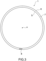
3 ist eine Seitenansicht auf einer anderen Seite, welche einen schematischen Aufbau des Dichtrings gemäß der ersten Ausführungsform der vorliegenden Erfindung darstellt. 3 is a side view on another side showing a schematic structure of the seal ring according to the first embodiment of the present invention.
-
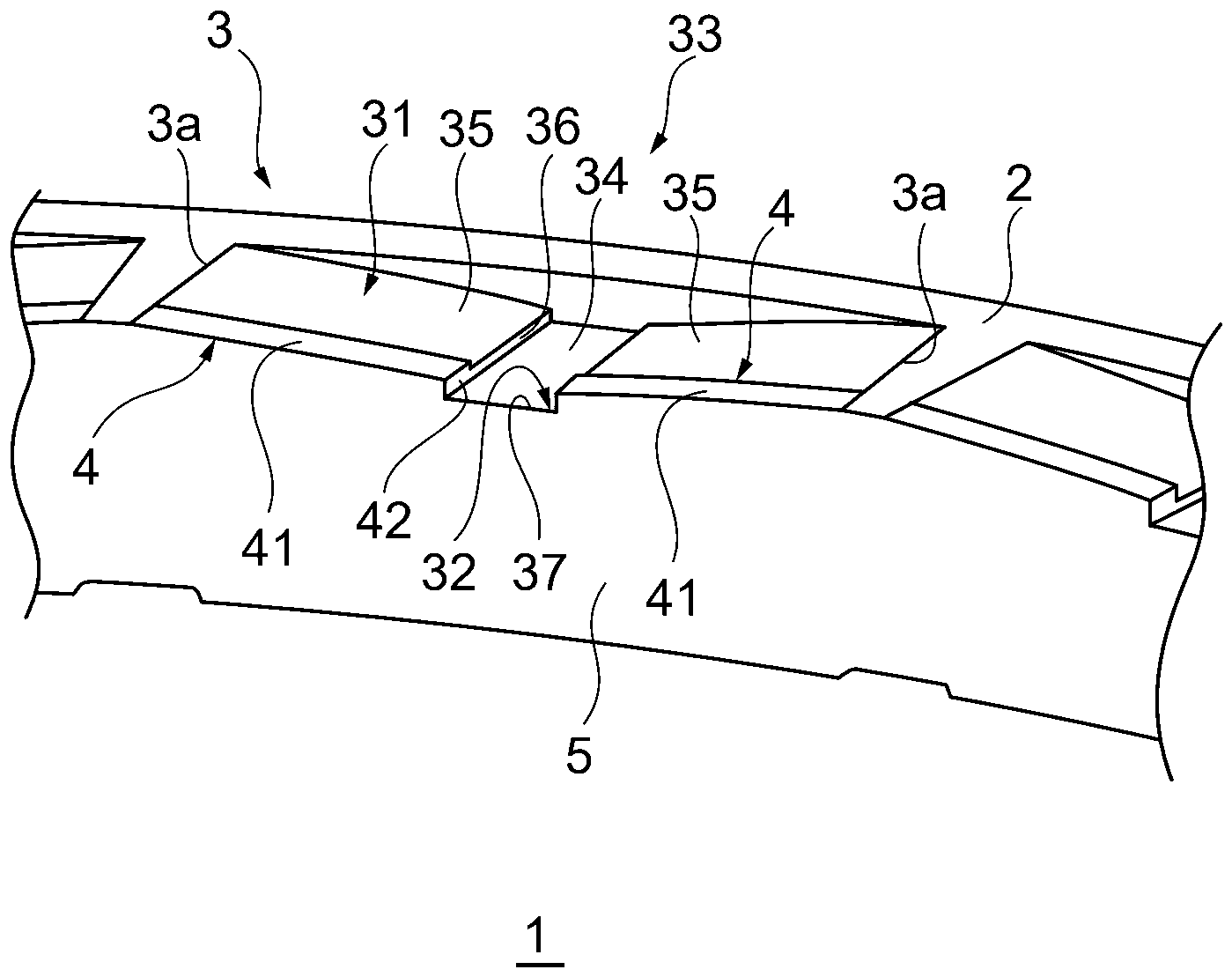
4 ist eine teilweise vergrößerte perspektivische Ansicht, welche einen schematischen Aufbau des Dichtrings gemäß der ersten Ausführungsform der vorliegenden Erfindung darstellt. 4 is a partially enlarged perspective view showing a schematic structure of the seal ring according to the first embodiment of the present invention.
-
5 ist eine teilweise vergrößerte Ansicht, welche den Dichtring gemäß 1 darstellt. 5 is a partially enlarged view showing the sealing ring according to 1 represents.
-
6 ist eine teilweise vergrößerte Schnittansicht des Schnitts A-A in 5. 6 is a partially enlarged sectional view of section AA in 5 .
-
7 ist eine teilweise vergrößerte Schnittansicht des Schnitts B-B in 5. 7 is a partially enlarged sectional view of section BB in 5 .
-
8 ist eine teilweise vergrößerte Schnittansicht des Schnitts B-B in 5, um Abwandlungen der Innenumfangswandfläche zu zeigen. 8 is a partially enlarged sectional view of section BB in 5 to show variations of the inner peripheral wall surface.
-
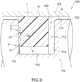
9 ist eine teilweise vergrößerte geschnittene Ansicht des Dichtrings unter Betriebsbedingungen, wobei der Dichtring gemäß der ersten Ausführungsform der vorliegenden Erfindung in einem Gehäuse eines Hydroaggregats als einzubauender Gegenstand und auf einer in einer Wellenbohrung als im Gehäuse gebildetes Durchgangsloch eingeführten Welle eingesetzt ist. 9 is a partially enlarged sectional view of the seal ring under operating conditions, wherein the seal ring according to the first embodiment of the present invention is installed in a housing of a hydraulic unit as an object to be installed and on a shaft inserted into a shaft bore as a through hole formed in the housing.
-
10 ist eine teilweise vergrößerte Seitenansicht, welche einen schematischen Aufbau eines Dichtrings gemäß der zweiten Ausführungsform der vorliegenden Erfindung darstellt, wobei ein Teil der Seitenfläche des Dichtrings auf einer Seite vergrößert ist. 10 is a partially enlarged side view illustrating a schematic structure of a seal ring according to the second embodiment of the present invention, with a part of the side surface of the seal ring on one side being enlarged.
-
11 ist eine teilweise vergrößerte perspektivische Ansicht, welche einen schematischen Aufbau des Dichtrings gemäß der zweiten Ausführungsform der vorliegenden Erfindung darstellt. 11 is a partially enlarged perspective view showing a schematic structure of the seal ring according to the second embodiment of the present invention.
-
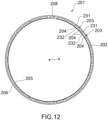
12 ist eine Seitenansicht auf einer Seite, welche einen schematischen Aufbau des Dichtrings gemäß der dritten Ausführungsform der vorliegenden Erfindung darstellt. 12 is a side view on one side showing a schematic structure of the seal ring according to the third embodiment of the present invention.
-
13 ist eine Vorderansicht, welche einen schematischen Aufbau des Dichtrings gemäß der dritten Ausführungsform der vorliegenden Erfindung darstellt. 13 is a front view illustrating a schematic structure of the seal ring according to the third embodiment of the present invention.
-
14 ist eine Seitenansicht auf einer anderen Seite, welche einen schematischen Aufbau eines Dichtrings gemäß der dritten Ausführungsform der vorliegenden Erfindung darstellt. 14 is a side view on another side showing a schematic structure of a seal ring according to the third embodiment of the present invention.
-
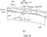
15 ist eine teilweise vergrößerte perspektivische Ansicht, welche einen schematischen Aufbau des Dichtrings gemäß der dritten Ausführungsform der vorliegenden Erfindung darstellt. 15 is a partially enlarged perspective view showing a schematic structure of the seal ring according to the third embodiment of the present invention.
-
16 ist eine teilweise vergrößerte Ansicht, welche den Dichtring gemäß 12 darstellt. 16 is a partially enlarged view showing the sealing ring according to 12 represents.
-
17 ist eine teilweise vergrößerte Schnittansicht des Schnitts A-A in 16. 17 is a partially enlarged sectional view of section AA in 16 .
-
18 ist eine teilweise vergrößerte Schnittansicht des Schnitts B-B in 16. 18 is a partially enlarged sectional view of section BB in 16 .
-
19 ist eine teilweise vergrößerte Schnittansicht in Schnitts B-B in 16, um Abwandlungen der Innenumfangswandfläche zu zeigen. 19 is a partially enlarged sectional view in section BB in 16 to show variations of the inner peripheral wall surface.
-
20 ist eine teilweise vergrößerte geschnittene Ansicht des Dichtrings im Gebrauchszustand, wobei der Dichtring gemäß der dritten Ausführungsform der vorliegenden Erfindung in einem Gehäuse eines Hydroaggregats als einzubauender Gegenstand und auf einer in einer Wellenbohrung als im Gehäuse gebildetes Durchgangsloch eingeführten Welle eingesetzt ist. 20 is a partially enlarged sectional view of the seal ring in use, wherein the seal ring according to the third embodiment of the present invention is installed in a housing of a hydraulic unit as an article to be installed and on a shaft inserted into a shaft bore as a through hole formed in the housing.
-
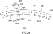
21 ist eine teilweise vergrößerte Seitenansicht, welche einen schematischen Aufbau eines Dichtrings gemäß der vierten Ausführungsform der vorliegenden Erfindung darstellt, wobei ein Teil der Seitenfläche des Dichtrings auf einer Seite vergrößert ist. 21 is a partially enlarged side view illustrating a schematic structure of a seal ring according to the fourth embodiment of the present invention, with a part of the side surface of the seal ring on one side being enlarged.
-
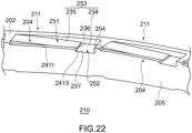
22 ist eine teilweise vergrößerte perspektivische Ansicht, welche einen schematischen Aufbau des Dichtrings gemäß der vierten Ausführungsform der vorliegenden Erfindung darstellt. 22 is a partially enlarged perspective view showing a schematic structure of the seal ring according to the fourth embodiment of the present invention.
-
23 ist eine Seitenansicht auf einer Seite, welche einen schematischen Aufbau des Dichtrings gemäß der fünften Ausführungsform der vorliegenden Erfindung darstellt. 23 is a side view on one side showing a schematic structure of the seal ring according to the fifth embodiment of the present invention.
-
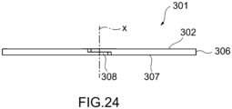
24 ist eine Vorderansicht, welche einen schematischen Aufbau des Dichtrings gemäß der fünften Ausführungsform der vorliegenden Erfindung darstellt. 24 is a front view illustrating a schematic structure of the seal ring according to the fifth embodiment of the present invention.
-
25 ist eine Seitenansicht auf einer anderen Seite, welche einen schematischen Aufbau des Dichtrings gemäß der fünften Ausführungsform der vorliegenden Erfindung darstellt. 25 is a side view on another side showing a schematic structure of the seal ring according to the fifth embodiment of the present invention.
-
26 ist eine teilweise vergrößerte perspektivische Ansicht, welche einen schematischen Aufbau des Dichtrings gemäß der fünften Ausführungsform der vorliegenden Erfindung darstellt. 26 is a partially enlarged perspective view showing a schematic structure of the seal ring according to the fifth embodiment of the present invention.
-
27 ist eine teilweise vergrößerte Ansicht, welche den Dichtring gemäß 23 darstellt. 27 is a partially enlarged view showing the sealing ring according to 23 represents.
-
28 ist eine teilweise vergrößerte Schnittansicht des Schnitts A-A in 27. 28 is a partially enlarged sectional view of section AA in 27 .
-
29 ist eine teilweise vergrößerte Schnittansicht des Schnitts B-B in 27. 29 is a partially enlarged sectional view of section BB in 27 .
-
30 ist eine teilweise vergrößerte Schnittansicht des Schnitts B-B in 27, um Abwandlungen der Innenumfangswandfläche zu zeigen. 30 is a partially enlarged sectional view of section BB in 27 to show variations of the inner peripheral wall surface.
-
31 ist eine teilweise vergrößerte geschnittene Ansicht des Dichtrings im Gebrauchszustand, wobei der Dichtring gemäß der fünften Ausführungsform der vorliegenden Erfindung in einem Gehäuse eines Hydroaggregats als einzubauender Gegenstand und auf einer in einer Wellenbohrung als im Gehäuse gebildetes Durchgangsloch eingeführten Welle eingesetzt ist. 31 is a partially enlarged sectional view of the seal ring in use, wherein the seal ring according to the fifth embodiment of the present invention is installed in a housing of a hydraulic unit as an article to be installed and on a shaft inserted into a shaft bore as a through hole formed in the housing.
-
32 ist eine teilweise vergrößerte Seitenansicht, welche einen schematischen Aufbau eines Dichtrings gemäß der sechsten Ausführungsform der vorliegenden Erfindung darstellt, wobei ein Teil der Seitenfläche des Dichtrings auf einer Seite vergrößert ist. 32 is a partially enlarged side view illustrating a schematic structure of a seal ring according to the sixth embodiment of the present invention, with a part of the side surface of the seal ring on one side being enlarged.
-
33 ist eine teilweise vergrößerte perspektivische Ansicht, welche einen schematischen Aufbau des Dichtrings gemäß der sechsten Ausführungsform der vorliegenden Erfindung darstellt. 33 is a partially enlarged perspective view showing a schematic structure of the seal ring according to the sixth embodiment of the present invention.
-
34 ist eine Seitenansicht auf einer Seite, welche einen schematischen Aufbau eines Dichtrings gemäß der siebten Ausführungsform der vorliegenden Erfindung darstellt. 34 is a side view on one side showing a schematic structure of a seal ring according to the seventh embodiment of the present invention.
-
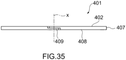
35 ist eine Vorderansicht, welche einen schematischen Aufbau des Dichtrings gemäß der siebten Ausführungsform der vorliegenden Erfindung darstellt. 35 is a front view illustrating a schematic structure of the seal ring according to the seventh embodiment of the present invention.
-
36 ist eine Seitenansicht auf einer anderen Seite, welche einen schematischen Aufbau des Dichtrings gemäß der siebten Ausführungsform der vorliegenden Erfindung darstellt. 36 is a side view on another side showing a schematic structure of the seal ring according to the seventh embodiment of the present invention.
-
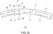
37 ist eine teilweise vergrößerte perspektivische Ansicht, welche einen schematischen Aufbau des Dichtrings gemäß der siebten Ausführungsform der vorliegenden Erfindung darstellt. 37 is a partially enlarged perspective view showing a schematic structure of the seal ring according to the seventh embodiment of the present invention.
-
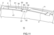
38 ist eine teilweise vergrößerte Ansicht, welche den Dichtring gemäß 34 darstellt. 38 is a partially enlarged view showing the sealing ring according to 34 represents.
-
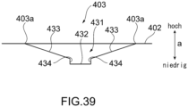
39 ist eine teilweise vergrößerte Ansicht des Schnitts A-A in 38. 39 is a partially enlarged view of section AA in 38 .
-
40 ist eine Ansicht des Schnitts B-B in 38. 40 is a view of section BB in 38 .
-
41 ist eine teilweise vergrößerte geschnittene Ansicht des Dichtrings im Gebrauchszustand, wobei der Dichtring gemäß der siebten Ausführungsform der vorliegenden Erfindung in einem Gehäuse eines Hydroaggregats als einzubauender Gegenstand und in einer Wellenbohrung als im Gehäuse gebildetes Durchgangsloch eingeführten Welle eingesetzt ist. 41 is a partially enlarged sectional view of the seal ring in use, wherein the seal ring according to the seventh embodiment of the present invention is installed in a housing of a hydraulic unit as an object to be installed and inserted into a shaft bore as a through hole formed in the housing.
-
42 ist eine teilweise vergrößerte Seitenansicht, welche einen schematischen Aufbau eines Dichtrings gemäß der achten Ausführungsform der vorliegenden Erfindung darstellt, wobei ein Teil der Seitenfläche des Dichtrings auf einer Seite vergrößert ist. 42 is a partially enlarged side view illustrating a schematic structure of a seal ring according to the eighth embodiment of the present invention, with a part of the side surface of the seal ring on one side being enlarged.
-
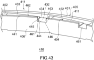
43 ist eine teilweise vergrößerte perspektivische Ansicht, welche einen schematischen Aufbau des Dichtrings gemäß der achten Ausführungsform der vorliegenden Erfindung darstellt. 43 is a partially enlarged perspective view showing a schematic structure of the seal ring according to the eighth embodiment of the present invention.
-
44 ist eine Seitenansicht auf einer Seite, welche einen schematischen Aufbau des Dichtrings gemäß der neunten Ausführungsform der vorliegenden Erfindung darstellt. 44 is a side view on one side showing a schematic structure of the seal ring according to the ninth embodiment of the present invention.
-
45 ist eine Vorderansicht, welche einen schematischen Aufbau eines Dichtrings gemäß der neunten Ausführungsform der vorliegenden Erfindung darstellt. 45 is a front view illustrating a schematic structure of a seal ring according to the ninth embodiment of the present invention.
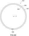
-
46 ist eine Seitenansicht auf einer anderen Seite, welche einen schematischen Aufbau des Dichtrings gemäß der neunten Ausführungsform der vorliegenden Erfindung darstellt. 46 is a side view on another side showing a schematic structure of the seal ring according to the ninth embodiment of the present invention.
-
47 ist eine teilweise vergrößerte perspektivische Ansicht, welche einen schematischen Aufbau des Dichtrings gemäß der neunten Ausführungsform der vorliegenden Erfindung darstellt. 47 is a partially enlarged perspective view showing a schematic structure of the seal ring according to the ninth embodiment of the present invention.
-
48 ist eine teilweise vergrößerte Ansicht, welche einen Aufbau des Dichtrings gemäß 44 darstellt. 48 is a partially enlarged view showing a structure of the sealing ring according to 44 represents.
-
49 ist eine teilweise vergrößerte Schnittansicht des Schnitts A-A in 48. 49 is a partially enlarged sectional view of section AA in 48 .
-
50 ist eine teilweise vergrößerte geschnittene Ansicht des Dichtrings im Gebrauchszustand, wobei der Dichtring gemäß der neunten Ausführungsform der vorliegenden Erfindung in einem Gehäuse eines Hydroaggregats als einzubauender Gegenstand und auf einer in einer Wellenbohrung als im Gehäuse gebildetes Durchgangsloch eingeführten Welle eingesetzt ist. 50 is a partially enlarged sectional view of the seal ring in use, wherein the seal ring according to the ninth embodiment of the present invention is installed in a housing of a hydraulic unit as an article to be installed and on a shaft inserted into a shaft bore as a through hole formed in the housing.
-
51 ist eine teilweise vergrößerte Ansicht, welche einen Aufbau eines herkömmlichen Dichtrings darstellt. 51 is a partially enlarged view showing a structure of a conventional sealing ring.
-
52 ist eine teilweise vergrößerte Ansicht, welche zur Erläuterung für die Wirkung und Effekte durch einen Schlitz im Dichtring der vorliegenden Erfindung dient. 52 is a partially enlarged view useful for explaining the action and effects of a slit in the seal ring of the present invention.
-
53 ist eine teilweise vergrößerte Seitenansicht, welche einen schematischen Aufbau eines Dichtrings gemäß der zehnten Ausführungsform der vorliegenden Erfindung darstellt, wobei ein Teil der Seitenfläche des Dichtrings auf einer Seite vergrößert ist, 53 is a partially enlarged side view showing a schematic structure of a seal ring according to the tenth embodiment of the present invention, with a part of the side surface of the seal ring on one side being enlarged,
-
54 ist eine teilweise vergrößerte perspektivische Ansicht, welche einen schematischen Aufbau des Dichtrings gemäß der zehnten Ausführungsform der vorliegenden Erfindung darstellt. 54 is a partially enlarged perspective view showing a schematic structure of the seal ring according to the tenth embodiment of the present invention.
-
55 ist eine Seitenansicht auf einer Seite, welche einen schematischen Aufbau des Dichtrings gemäß der elften Ausführungsform der vorliegenden Erfindung darstellt. 55 is a side view on one side showing a schematic structure of the seal ring according to the eleventh embodiment of the present invention.
-
56 ist eine Vorderansicht, welche einen schematischen Aufbau des Dichtrings gemäß der elften Ausführungsform der vorliegenden Erfindung darstellt. 56 is a front view illustrating a schematic structure of the seal ring according to the eleventh embodiment of the present invention.
-
57 ist eine Seitenansicht auf einer anderen Seite, welche einen schematischen Aufbau des Dichtrings gemäß der elften Ausführungsform der vorliegenden Erfindung darstellt. 57 is a side view on another side showing a schematic structure of the seal ring according to the eleventh embodiment of the present invention.
-
58 ist eine teilweise vergrößerte perspektivische Ansicht, welche einen schematischen Aufbau des Dichtrings gemäß der elften Ausführungsform der vorliegenden Erfindung darstellt. 58 is a partially enlarged perspective view showing a schematic structure of the seal ring according to the eleventh embodiment of the present invention.
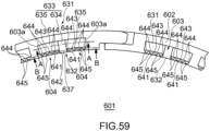
-
59 ist eine teilweise vergrößerte Ansicht, welche den Dichtring gemäß 55 darstellt. 59 is a partially enlarged view showing the sealing ring according to 55 represents.
-
60 ist eine teilweise vergrößerte Schnittansicht des Schnitts A-A in 59. 60 is a partially enlarged sectional view of section AA in 59 .
-
61 ist eine teilweise vergrößerte Ansicht des Schnitts B-B in 59. 61 is a partially enlarged view of section BB in 59 .
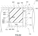
-
62 ist eine teilweise vergrößerte geschnittene Ansicht des Dichtrings im Gebrauchszustand, wobei der Dichtring gemäß der elften Ausführungsform der vorliegenden Erfindung in einem Gehäuse eines Hydroaggregats als einzubauender Gegenstand und auf einer in einer Wellenbohrung als im Gehäuse gebildetes Durchgangsloch eingeführten Welle eingesetzt ist. 62 is a partially enlarged sectional view of the seal ring in use, wherein the seal ring according to the eleventh embodiment of the present invention is installed in a housing of a hydraulic unit as an article to be installed and on a shaft inserted into a shaft bore as a through hole formed in the housing.
-
63 ist eine teilweise vergrößerte Seitenansicht, welche einen schematischen Aufbau eines Dichtrings gemäß der zwölften Ausführungsform der vorliegenden Erfindung darstellt, wobei ein Teil der Seitenfläche des Dichtrings auf einer Seite vergrößert ist. 63 is a partially enlarged side view illustrating a schematic structure of a seal ring according to the twelfth embodiment of the present invention, with a part of the side surface of the seal ring on one side being enlarged.
-
64 ist eine teilweise vergrößerte perspektivische Ansicht, welche einen Schnittansicht Aufbau eines Dichtrings gemäß der zwölften Ausführungsform der vorliegenden Erfindung darstellt. 64 is a partially enlarged perspective view showing a sectional structure of a seal ring according to the twelfth embodiment of the present invention.
-
65 ist eine teilweise vergrößerte perspektivische Ansicht, um eine Abwandlung einer Vertiefung im Dichtring gemäß der elften Ausführungsform der vorliegenden Erfindung darzustellen. 65 is a partially enlarged perspective view to show a modification of a recess in the seal ring according to the eleventh embodiment of the present invention.
-
66 ist eine teilweise vergrößerte perspektivische Ansicht, um eine Abwandlung einer Vertiefung im Dichtring gemäß der zwölften Ausführungsform der vorliegenden Erfindung darzustellen. 66 is a partially enlarged perspective view to show a modification of a recess in the seal ring according to the twelfth embodiment of the present invention.
-
67 ist eine teilweise vergrößerte perspektivische Ansicht, um eine Abwandlung der Vertiefung im Dichtring gemäß der elften Ausführungsform der vorliegenden Erfindung darzustellen. 67 is a partially enlarged perspective view to show a modification of the recess in the seal ring according to the eleventh embodiment of the present invention.
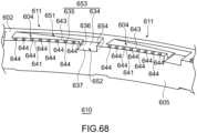
-
68 ist eine teilweise vergrößerte perspektivische Ansicht, um eine Abwandlung der Einsenkung im Dichtring gemäß der zwölften Ausführungsform der vorliegenden Erfindung darzustellen. 68 is a partially enlarged perspective view to show a modification of the recess in the seal ring according to the twelfth embodiment of the present invention.
[Formen zur Ausführung der Erfindung][Forms for carrying out the invention]
Nachfolgend wird unter Bezugnahme auf die Figuren eine Ausführungsform der vorliegenden Erfindung erläutert.
1 ist eine Seitenansicht auf einer Seite, welche einen schematischen Aufbau eines Dichtrings 1 gemäß der ersten Ausführungsform der vorliegenden Erfindung darstellt, 2 ist eine Vorderansicht, welche einen schematischen Aufbau des Dichtrings 1 darstellt und 3 ist eine Seitenansicht auf einer anderen Seite, welche einen schematischen Aufbau des Dichtrings 1 darstellt. 4 ist eine teilweise vergrößerte perspektivische Ansicht, welche einen schematischen Aufbau des Dichtrings 1 darstellt.An embodiment of the present invention will be explained below with reference to the figures.
1 is a side view on one side showing a schematic structure of a seal ring 1 according to the first embodiment of the present invention, 2 is a front view showing a schematic structure of the sealing ring 1 and 3 is a side view on another side showing a schematic structure of the sealing ring 1. 4 is a partially enlarged perspective view showing a schematic structure of the sealing ring 1.
Der Dichtring 1 gemäß der vorliegenden Ausführungsform ist eine Dichtungsvorrichtung zum Dichten eines ringförmigen Spaltes zwischen einer Welle und einer Wellenbohrung, in die die Welle eingeführt wird, und bei Fahrzeugen oder universalen Maschinen wird der Dichtring 1 zum Dichten eines Raumes zwischen einer relativ zueinander drehenden Welle und einer im Gehäuse gebildeten Wellenbohrung verwendet, in die die Welle eingeführt wird. Der Dichtring 1 wird, zum Beispiel, beim automatischen Getriebe oder stufenlosen Getriebe zum Erhalten des hydraulischen Drucks des Hydrauliköls in die an der Außenumfangsfläche der Welle gebildete Nut eingesetzt und verwendet. Der Gegenstand, auf den der Dichtring 1 gemäß der vorliegenden Ausführungsform angewendet wird, ist nicht auf den Obigen beschränkt.The seal ring 1 according to the present embodiment is a sealing device for sealing an annular gap between a shaft and a shaft hole into which the shaft is inserted. In vehicles or general-purpose machines, the seal ring 1 is used to seal a space between a relatively rotating shaft and a shaft hole formed in the housing into which the shaft is inserted. The seal ring 1 is used, for example, in an automatic transmission or a continuously variable transmission for receiving hydraulic pressure of hydraulic oil, and inserted into the groove formed on the outer peripheral surface of the shaft. The subject matter to which the seal ring 1 according to the present embodiment is applied is not limited to the above.
Wie in 1 gezeigt, ist der Dichtring 1 ringförmig um eine Achse x und umfasst wenigstens eine Seitenfläche 2, die eine die eine in eine Richtung der Achse weisende Fläche ist, und eine Mehrzahl von Vertiefungen 3, die in Umfangsrichtung voneinander beabstandet an der Seitenfläche 2 gebildet sind, sowie eine Mehrzahl von Innenumfangswandteilen 4, die jeweils entsprechend den Vertiefungen 3 gebildet sind. Die Vertiefung 3 weist den Staudruckteil 31, der sich an der Seitenfläche 2 konvergierend in Umfangsrichtung erstreckt, und den Einführungsteil 32 auf, der sich vom Staudruckteil 31 zur Innenumfangsseite erstreckt und den Staudruckteil 31 zur Innenumfangsseite öffnet. Eines oder zwei der Innenumfangswandteile 4 ist an jeder Vertiefung 3 vorgesehen und jeder Innenumfangswandteil 4 weist eine Innenumfangswandfläche 41 auf, die ein durch den Staudruckteil 31 und den Einführungsteil 32 der entsprechenden Vertiefung 3 auf der Innenumfangsseite der entsprechenden Vertiefung 3 begrenzter Teil ist und die eine an der Seitenfläche 2 folgende Fläche ist. Die Innenumfangswandfläche 41 ist von der Seitenfläche 2 sinkend zur Seitenfläche 2 geneigt und erstreckt sich zum Einführungsteil 32.As in 1 As shown, the sealing ring 1 is annular around an axis x and comprises at least one side surface 2, which is a surface facing in a direction of the axis, and a plurality of recesses 3 formed circumferentially spaced from each other on the side surface 2, as well as a plurality of inner peripheral wall parts 4 each formed corresponding to the recesses 3. The recess 3 has the back pressure part 31 extending convergently in the circumferential direction on the side surface 2, and the insertion part 32 extending from the back pressure part 31 to the inner peripheral side and opening the back pressure part 31 to the inner peripheral side. One or two of the inner peripheral wall parts 4 are provided on each recess 3, and each inner peripheral wall part 4 has an inner peripheral wall surface 41 forming a wall formed by the back pressure part 31 and the insertion part 32 of the corresponding recess 3 on the inner peripheral side of the corresponding recess 3. limited part and is a surface following the side surface 2. The inner peripheral wall surface 41 is inclined downwards from the side surface 2 to the side surface 2 and extends to the insertion part 32.
Im Einzelnen, ist die Seitenfläche 2 eine Seitenfläche, die als Gleitfläche gebildet ist, die an eine Nutseitenfläche einer in der später beschriebenen Betriebsbedingung an der Welle gebildeten Nut angepresst wird und der Dichtring 1 gemäß der vorliegenden Ausführungsform weist, wie in 1 und 3 gezeigt, nur eine Seitenfläche 2 als Gleitfläche auf. Der Dichtring 1 kann auch zwei Seitenflächen 2 als Gleitfläche aufweisen, nämlich eine Seitenfläche 2 als Gleitfläche an der anderen Seitenfläche. In diesem Fall wird die Einbaurichtung des Dichtrings 1 zur an der Welle gebildeten Nut nicht eingeschränkt und daher wird der Einbau des Dichtrings 1 erleichtert.In detail, the side surface 2 is a side surface formed as a sliding surface which is pressed against a groove side surface of a groove formed on the shaft in the later-described operating condition, and the seal ring 1 according to the present embodiment has, as shown in 1 and 3 As shown, only one side surface 2 serves as a sliding surface. The sealing ring 1 may also have two side surfaces 2 serving as a sliding surface, namely one side surface 2 serving as a sliding surface on the other side surface. In this case, the installation direction of the sealing ring 1 relative to the groove formed on the shaft is not restricted, and therefore the installation of the sealing ring 1 is facilitated.
In Bezug auf den Dichtring 1 ist, wie in 1 bis 3 gezeigt, der Querschnitt der Fläche entlang der Achse x rechteckig oder im Wesentlichen rechteckig, und der Dichtring 1 weist eine Innenumfangsfläche 5, die eine der Innenumfangsseite zugewandte Fläche ist, und eine der Außenumfangsseite zugewandte Außenumfangsfläche 6, sowie eine Seitenfläche 2, und eine Seitenfläche 7 auf, die eine andere Seitenfläche ist. Die Innenumfangsfläche 5 ist, zum Beispiel, eine zylindrische Fläche oder eine im Wesentlichen zylindrische Fläche, die um die Achse x oder im Wesentlichen um die Achse x angeordnet ist, und die Außenumfangsfläche 6 ist eine der Innenumfangsfläche 5 abgewandte Fläche, wie zum Beispiel, eine zylindrische Fläche oder eine im Wesentlichen zylindrische Fläche, die um die Achse x oder im Wesentlichen um die Achse x angeordnet ist. Die Seitenfläche 2 ist eine ringförmige Fläche entlang einer flachen Ebene oder einer im Wesentlichen flachen Ebene, die orthogonal oder im Wesentlichen orthogonal zur Achse x ist, und erstreckt sich zwischen der Innenumfangsfläche 5 und der Außenumfangsfläche 6. Die Seitenfläche 7 ist eine der Seitenfläche 2 abgewandte Fläche und eine ringförmige Fläche entlang einer flachen Ebene oder einer im Wesentlichen flachen Ebene, die orthogonal oder im Wesentlichen orthogonal zur Achse x ist, und erstreckt sich zwischen der Innenumfangsfläche 5 und der Außenumfangsfläche 6.With regard to the sealing ring 1, as in 1 to 3 As shown, the cross-section of the surface along the axis x is rectangular or substantially rectangular, and the sealing ring 1 has an inner peripheral surface 5, which is a surface facing the inner peripheral side, and an outer peripheral surface 6 facing the outer peripheral side, as well as a side surface 2, and a side surface 7, which is another side surface. The inner peripheral surface 5 is, for example, a cylindrical surface or a substantially cylindrical surface arranged around the axis x or substantially around the axis x, and the outer peripheral surface 6 is a surface facing away from the inner peripheral surface 5, such as a cylindrical surface or a substantially cylindrical surface arranged around the axis x or substantially around the axis x. The side surface 2 is an annular surface along a flat plane or a substantially flat plane that is orthogonal or substantially orthogonal to the axis x, and extends between the inner peripheral surface 5 and the outer peripheral surface 6. The side surface 7 is a surface facing away from the side surface 2 and an annular surface along a flat plane or a substantially flat plane that is orthogonal or substantially orthogonal to the axis x, and extends between the inner peripheral surface 5 and the outer peripheral surface 6.
An der Seitenfläche 2 als Gleitfläche sind, wie oben erwähnt, eine Mehrzahl von Vertiefungen 3 gebildet, und die Vertiefungen 3 sind um die Achse x in gleichmäßigem Winkelabstand oder im Wesentlichen in gleichmäßigem Winkelabstand gebildet. Wie in 4 und 5 gezeigt, ist die Vertiefung 3 ein von der Seitenfläche 2 zur Seitenfläche 7 vertiefender Teil, und ist im Wesentlichen T-förmig in Richtung der Achse x gesehen. Die Vertiefung 3 ist auf der Seite der Innenumfangsfläche 5 in der Seitenfläche 2 vorgesehen und steht im Gebrauchszustand aus der Seitenfläche der Nut der Welle nicht zur Außenumfangsseite vor.On the side surface 2 as a sliding surface, as mentioned above, a plurality of recesses 3 are formed, and the recesses 3 are formed around the axis x at a uniform angular distance or substantially at a uniform angular distance. As shown in 4 and 5 As shown, the recess 3 is a recessed portion from the side surface 2 to the side surface 7, and is substantially T-shaped in the direction of the axis x. The recess 3 is provided on the side of the inner peripheral surface 5 in the side surface 2 and, in the use state, does not protrude from the side surface of the groove of the shaft to the outer peripheral side.
Im Einzelnen ist, wie in 4 und 5 gezeigt, der Staudruckteil 31 in der Vertiefung 3 von der Außenumfangsfläche 6 und der Innenumfangsfläche 5 in Radialrichtung beabstandet, und erstreckt sich in Umfangsrichtung kreisbogenförmig um die Achse x oder im Wesentlichen um die Achse x oder im Wesentlichen kreisbogenförmig um die Achse x oder im Wesentlichen um die Achse x. Der Staudruckteil 31 ist in Radialrichtung auf der Seite der Innenumfangsfläche 5 vorgesehen. Der Staudruckteil 31 weist, im Einzelnen, eine Grundfläche 33 auf, die eine Fläche ist, die einer Seite zugewandt ist, der die Seitenfläche 2 zugewandt ist, und die Grundfläche 33 weist eine Einführungsfläche 34, die mit dem Einführungsteil 32 verbunden ist, und eine oder zwei Staudruckflächen 35 auf, die sich zwischen der Einführungsfläche 34 und der Seitenfläche 2 erstrecken. In Bezug auf den Dichtring 1 gemäß der vorliegenden Ausführungsform weist die Grundfläche 33 zwei Staudruckflächen 35 auf.In detail, as in 4 and 5 As shown, the back pressure part 31 in the recess 3 is spaced radially from the outer peripheral surface 6 and the inner peripheral surface 5, and extends circumferentially in a circular arc around the axis x or substantially around the axis x or substantially in a circular arc around the axis x or substantially around the axis x. The back pressure part 31 is provided in the radial direction on the side of the inner peripheral surface 5. Specifically, the back pressure part 31 has a base surface 33, which is a surface facing a side to which the side surface 2 faces, and the base surface 33 has an introduction surface 34 connected to the introduction part 32, and one or two back pressure surfaces 35 extending between the introduction surface 34 and the side surface 2. With respect to the seal ring 1 according to the present embodiment, the base surface 33 has two back pressure surfaces 35.
Die Einführungsfläche 34 befindet sich, wie in 4 und 6 gezeigt, an der tiefsten Stelle im Staudruckteil 31, und ist eine flache Ebene oder eine im Wesentlichen flache Ebene, und erstreckt sich rechteckförmig oder im Wesentlichen rechteckförmig. In Bezug auf die Vertiefung 3, ist die Richtung der Achse x auch als Höhenrichtung angegeben, und in dieser Höhenrichtung (in Pfeilrichtung a in 6 und 7) ist die innere Seite des Dichtrings 1 als niedrige Seite und die Seitenfläche 2 als höhere Seite vorgesehen. Die Einführungsfläche 34 kann eine gekrümmte Ebene sein und muss nicht rechteckförmig sein. Die Staudruckfläche 35 ist von der Einführungsfläche 34 steigend zur Seitenfläche 2 geneigt, erstreckt sich in Umfangsrichtung zur Seitenfläche 2, ist eine flache Ebene oder eine im Wesentlichen flache Ebene und erstreckt sich rechteckförmig oder im Wesentlichen rechteckförmig. Die Staudruckfläche 35 erstreckt sich zwischen der Einführungsfläche 34 und der Seitenfläche 2 und schließt glatt an der Seitenfläche 2 an. Die Staudruckfläche 35 kann eine gekrümmte Ebene sein und muss nicht rechteckförmig sein. Die Staudruckfläche 35 kann beispielsweise zur Seitenfläche 2 verbreitend oder verjüngend trapezförmig sein. Die Staudruckfläche 35 ist über eine Stufenfläche 36, die in Richtung der Achse x eine zur Seitenfläche 7 abgesenkte Stufe bildet, mit der Einführungsfläche 34 verbunden. Die Vertiefung 3 muss jedoch keine Stufenfläche 36 aufweisen und die Staudruckfläche 35 kann direkt mit der Einführungsfläche 34 verbunden werden.The introduction surface 34 is located, as in 4 and 6 shown, at the lowest point in the dynamic pressure part 31, and is a flat plane or a substantially flat plane, and extends rectangularly or substantially rectangularly. With respect to the depression 3, the direction of the axis x is also indicated as the height direction, and in this height direction (in the direction of arrow a in 6 and 7 ) the inner side of the sealing ring 1 is provided as the low side and the side surface 2 as the higher side. The introduction surface 34 can be a curved plane and does not have to be rectangular. The dynamic pressure surface 35 is inclined from the introduction surface 34 so as to rise towards the side surface 2, extends in the circumferential direction to the side surface 2, is a flat plane or a substantially flat plane and extends rectangularly or substantially rectangularly. The dynamic pressure surface 35 extends between the introduction surface 34 and the side surface 2 and smoothly adjoins the side surface 2. The dynamic pressure surface 35 can be a curved plane and does not have to be rectangular. The dynamic pressure surface 35 can, for example, be trapezoidal, widening or tapering towards the side surface 2. The dynamic pressure surface 35 is connected to the introduction surface 34 via a step surface 36 which forms a step in the direction of the axis x that is lowered towards the side surface 7. However, the recess 3 does not need to have a step surface 36 and the dynamic pressure surface 35 can be directly connected to the introduction surface 34.
In der Vertiefung 3 sind, wie oben erwähnt, zwei Staudruckflächen 35 gebildet und die Staudruckflächen 35 sind in Umfangsrichtung symmetrisch um die Einführungsfläche 34 in der Grundfläche 33 gebildet. Das heißt, die eine Staudruckfläche 35 erstreckt sich von einem Ende in Umfangsrichtung der Einführungsfläche 34 zur Seitenfläche 2 in der einen Richtung in Umfangsrichtung und die andere Staudruckfläche 35 erstreckt sich vom anderen Ende in Umfangsrichtung der Einführungsfläche 34 zur Seitenfläche 2 in der anderen Richtung in Umfangsrichtung. Der Staudruckteil 31 ist so gebildet, dass dessen Position im unten erwähnten Gebrauchszustand nicht von der Seitenfläche der kontaktierenden Nut der Welle zur Außenumfangsseite übersteht.In the depression 3, as mentioned above, two pressure surfaces 35 are formed and the pressure Pressure surfaces 35 are formed circumferentially symmetrically around the insertion surface 34 in the base surface 33. That is, one back pressure surface 35 extends from one circumferential end of the insertion surface 34 to the side surface 2 in one circumferential direction, and the other back pressure surface 35 extends from the other circumferential end of the insertion surface 34 to the side surface 2 in the other circumferential direction. The back pressure part 31 is formed such that its position does not protrude from the side surface of the contacting groove of the shaft to the outer peripheral side in the use state mentioned below.
In Bezug auf den Einführungsteil 32 der Vertiefung 3 ist, wie in 4 und 5 gezeigt, eine Aussparung an der Innenumfangsfläche 5 zum Öffnen zur Seitenfläche 2 gebildet, und der Einführungsteil 32 ist mit dem Staudruckteil 31 an einem Ende (Ende 3a) in Umfangsrichtung des Staudruckteils 31 verbunden. Im Einzelnen, ist der Einführungsteil 32 mit der Einführungsfläche 34 und der Stufenfläche 36 des Staudruckteils 31 verbunden und weist eine Grundfläche 37 auf, die an der Einführungsfläche 34 anschließt. Die Grundfläche 37 ist glatt mit der Einführungsfläche 34 des Staudruckteils 31 verbunden und die Grundfläche 37 ist beispielerweise eine Fläche, die auf gleicher Höhe mit der Einführungsfläche 34 positioniert ist. Mit dem Einführungsteil 32 ist ein Durchgang gebildet, der im Dichtring 1 von der Innenumfangsfläche 5 zum Staudruckteil 31 in Verbindung stehen.With regard to the introductory part 32 of the recess 3, as in 4 and 5 As shown, a recess is formed on the inner peripheral surface 5 for opening to the side surface 2, and the insertion part 32 is connected to the back pressure part 31 at one end (end 3a) in the circumferential direction of the back pressure part 31. Specifically, the insertion part 32 is connected to the insertion surface 34 and the step surface 36 of the back pressure part 31 and has a base surface 37 that adjoins the insertion surface 34. The base surface 37 is smoothly connected to the insertion surface 34 of the back pressure part 31, and the base surface 37 is, for example, a surface that is positioned at the same level as the insertion surface 34. A passage is formed with the insertion part 32, which communicates in the seal ring 1 from the inner peripheral surface 5 to the back pressure part 31.
Wie unten erwähnt, steht die Vertiefung 3 in Verbindung mit dem an der Innenumfangsfläche 5 angrenzenden Raum im Gebrauchszustand, in dem die Seitenfläche 2 des Dichtrings 1 in Kontakt mit der Seitenfläche der Nut der Welle steht, und konkret steht der Staudruckteil 31 über den Einführungsteil 32 in Verbindung mit dem an der Innenumfangsfläche 5 angrenzenden Raum. In den Gebrauchszustand bildet der Staudruckteil 31 einen Raum, der sich zwischen dem Staudruckteil 31 und der Seitenfläche der Nut der Welle in Umfangsrichtung erstreckt, und der Staudruckfläche 35 bildet einen Raum, der sich zwischen der Staudruckfläche 35 und der Seitenfläche der Nut der Welle in Umfangsrichtung erstreckt, dessen Höhe (Breite in Höhenrichtung) sich allmählich von der Einführungsfläche 34 zum Seitenfläche 2 verkleinert.As mentioned below, the recess 3 communicates with the space adjacent to the inner peripheral surface 5 in the use state in which the side surface 2 of the seal ring 1 is in contact with the side surface of the shaft groove, and specifically, the back pressure part 31 communicates with the space adjacent to the inner peripheral surface 5 via the insertion part 32. In the use state, the back pressure part 31 forms a space extending circumferentially between the back pressure part 31 and the side surface of the shaft groove, and the back pressure surface 35 forms a space extending circumferentially between the back pressure surface 35 and the side surface of the shaft groove, the height (width in the height direction) of which gradually decreases from the insertion surface 34 to the side surface 2.
Wie oben erwähnt, sind eine Mehrzahl von Innenumfangswandteilen 4 jeweils entsprechend den Vertiefungen 3, und im Einzelnen sind, wie in 4 und 5 gezeigt, zwei Innenumfangswandteile 4 für jede Vertiefung 3 gebildet. Der Innenumfangswandteil 4 ist ein Teil, der durch den Teil in Umfangsrichtung, an der sich die eine der Staudruckflächen 35 des Staudruckteils 31 erstreckt, den Einführungsteil 32 und die Innenumfangsfläche 5 begrenzt ist, und der Innenumfangswandteil 4 liegt an der Staudruckfläche 35 des Staudruckteils 31 auf der Innenumfangsseite an und ragt höher als die Staudruckfläche 35 heraus. Der Innenumfangswandteil 4 weist eine Innenumfangswandfläche 41 und eine Stirnfläche 42 auf, die durch den Einführungsteil 32 gebildet ist und sich entlang der Achse x erstreckt.As mentioned above, a plurality of inner peripheral wall parts 4 are respectively formed corresponding to the recesses 3, and in detail, as shown in 4 and 5 As shown, two inner peripheral wall parts 4 are formed for each recess 3. The inner peripheral wall part 4 is a part defined by the part in the circumferential direction where one of the back pressure surfaces 35 of the back pressure part 31 extends, the insertion part 32, and the inner peripheral surface 5, and the inner peripheral wall part 4 abuts against the back pressure surface 35 of the back pressure part 31 on the inner peripheral side and protrudes higher than the back pressure surface 35. The inner peripheral wall part 4 has an inner peripheral wall surface 41 and an end surface 42 formed by the insertion part 32 and extending along the axis x.
Die Innenumfangswandfläche 41 des Innenumfangswandteils 4 ist der Seite zugewandt, der die Seitenfläche 2 zugewandt ist und erstreckt sich in Umfangsrichtung in demselben Bereich oder in im Wesentlichen demselben Bereich wie die Staudruckfläche 35. Im Einzelnen erstreckt sich die Innenumfangswandfläche 41 in Umfangsrichtung von derselben Stelle wie die Stufenfläche 36 des Staudruckteils 31 zu derselben Stelle wie das Ende 3a des Staudruckteils 31 oder von derselben Stelle wie die Stufenfläche 36 des Staudruckteils 31 zu der Nähe derselben Stelle wie das Ende 3a des Staudruckteils 31. Das heißt, ein Ende 41a, das mit der Seitenfläche 2 der Innenumfangswandfläche 41 verbunden ist, kann in Umfangsrichtung entweder dasselbe wie das Ende 3a sein, an dem die Staudruckfläche 35 mit der Seitenfläche 2 verbunden ist, oder sich in der Nähe des Endes 3a befinden. In Bezug auf den dargestellten Dichtring 1, sind das Ende 41a und das Ende 3a an denselben Stellen in Umfangsrichtung positioniert. Wenn sich das Ende 41a in der Nähe des Endes 3a in Umfangsrichtung befindet, befindet sich das Ende 41a der Innenumfangswandfläche 41 bevorzugt näher zum Einführungsteil 32 (innen) als das Ende 3a der Staudruckfläche 35 in Umfangsrichtung.The inner peripheral wall surface 41 of the inner peripheral wall part 4 faces the side to which the side surface 2 faces and extends circumferentially in the same range or substantially the same range as the back pressure surface 35. Specifically, the inner peripheral wall surface 41 extends circumferentially from the same position as the step surface 36 of the back pressure part 31 to the same position as the end 3a of the back pressure part 31, or from the same position as the step surface 36 of the back pressure part 31 to the vicinity of the same position as the end 3a of the back pressure part 31. That is, an end 41a connected to the side surface 2 of the inner peripheral wall surface 41 may be circumferentially either the same as the end 3a at which the back pressure surface 35 is connected to the side surface 2, or may be located near the end 3a. With respect to the illustrated seal ring 1, the end 41a and the end 3a are positioned at the same circumferential positions. When the end 41a is located near the end 3a in the circumferential direction, the end 41a of the inner circumferential wall surface 41 is preferably located closer to the insertion part 32 (inside) than the end 3a of the back pressure surface 35 in the circumferential direction.
Wie in 4 und 7 gezeigt, ist die Innenumfangswandfläche 41 vom mit der Stirnfläche 42 verbundenen Teil steigend zur Seitenfläche 2 geneigt und erstreckt sich in Umfangsrichtung zur Seitenfläche 2, und die Innenumfangswandfläche 41 schließt glatt an der Seitenfläche 2 an. Die Innenumfangswandfläche 41 ist eine flache Ebene oder eine im Wesentlichen flache Ebene, und erstreckt sich rechteckförmig oder im Wesentlichen rechteckförmig. Die Innenumfangswandfläche 41 kann eine gekrümmte Ebene sein und muss nicht rechteckförmig sein. Die Innenumfangswandfläche 41 kann beispielsweise zur Seitenfläche 2 verbreitend oder verjüngend trapezförmig sein. Die Innenumfangswandfläche 41 kann eine Mehrzahl von flachen Ebenen oder im Wesentlichen flache Ebenen oder eine Mehrzahl von gekrümmten Ebenen oder im Wesentlichen gekrümmte Ebenen oder eine Fläche sein, die aus solchen Flächen aufeinander folgend gebildet ist. Wie beispielsweise 8 zeigt, kann die Innenumfangswandfläche 41 aus flache Ebenen oder im Wesentlichen flache Ebenen, deren Neigungswinkel zur Seitenfläche 2 allmählich größer werden, aufeinander folgend gebildet sein. Der Neigungswinkel α der Innenumfangswandfläche 41 zur Seitenfläche 2 ist kleiner als der Neigungswinkel β (siehe 6) der Staudruckfläche 35 zur Seitenfläche 2 (siehe 6 und 7).As in 4 and 7 As shown, the inner peripheral wall surface 41 is inclined upwards from the part connected to the end surface 42 toward the side surface 2 and extends circumferentially toward the side surface 2, and the inner peripheral wall surface 41 smoothly adjoins the side surface 2. The inner peripheral wall surface 41 is a flat plane or a substantially flat plane and extends rectangularly or substantially rectangularly. The inner peripheral wall surface 41 may be a curved plane and does not have to be rectangular. The inner peripheral wall surface 41 may, for example, be trapezoidal, widening or tapering toward the side surface 2. The inner peripheral wall surface 41 may be a plurality of flat planes or substantially flat planes, or a plurality of curved planes or substantially curved planes, or a surface formed from such surfaces successively. For example, 8 shows, the inner peripheral wall surface 41 may be formed of flat planes or substantially flat planes whose inclination angles to the side surface 2 gradually increase, successively. The inclination angle α of the inner peripheral wall surface 41 to the side surface 2 is smaller than the inclination angle β (see 6 ) of the dynamic pressure surface 35 to the side surface 2 (see 6 and 7 ).
In Bezug auf jede Vertiefung 3 sind, wie oben erwähnt, zwei Innenumfangswandteile 4 gebildet, und die Innenumfangswandteile 4 sind in Umfangsrichtung symmetrisch um den Einführungsteil 32 gebildet. Das heißt, der eine Innenumfangswandteil 4 erstreckt sich von einer Kante in Umfangsrichtung des Einführungsteils 32 zur Seitenfläche 2 in der einen Richtung in Umfangsrichtung und der andere Innenumfangswandteil 4 erstreckt sich von der anderen Kante in Umfangsrichtung des Einführungsteils 32 zur Seitenfläche 2 in der anderen Richtung in Umfangsrichtung.With respect to each recess 3, as mentioned above, two inner peripheral wall parts 4 are formed, and the inner peripheral wall parts 4 are formed circumferentially symmetrically around the insertion part 32. That is, one inner peripheral wall part 4 extends from one circumferential edge of the insertion part 32 to the side surface 2 in one circumferential direction, and the other inner peripheral wall part 4 extends from the other circumferential edge of the insertion part 32 to the side surface 2 in the other circumferential direction.
In den Gebrauchszustand, in dem die Seitenfläche 2 des Dichtrings 1 in Kontakt mit der Seitenfläche der Nut der Welle steht, liegt die Innenumfangswandfläche 41 des Innenumfangswandteils 4 der Seitenfläche der Nut der Welle gegenüber, wie unten erwähnt. Die Innenumfangswandfläche 41 ist zur Seitenfläche 2 geneigt, deshalb berührt die Innenumfangswandfläche 41 nicht die Seitenfläche der Nut und ein Raum wird zwischen der Seitenfläche der Nut gebildet. Der Raum ist keilförmig und dessen Höhe verkleinert sich allmählich von der Stirnfläche 42 zum Ende 41a.In the use state where the side surface 2 of the seal ring 1 is in contact with the side surface of the shaft groove, the inner peripheral wall surface 41 of the inner peripheral wall part 4 faces the side surface of the shaft groove, as mentioned below. The inner peripheral wall surface 41 is inclined toward the side surface 2, therefore, the inner peripheral wall surface 41 does not contact the side surface of the groove, and a space is formed between the side surface of the groove. The space is wedge-shaped, and its height gradually decreases from the end surface 42 to the end 41a.
Der Dichtring 1 besteht aus Kunststoff wie Polyetheretherketon (PEEK), Polyphenylensulfid (PPS) und Polytetrafluorethylen (PTFE). Die Umfangslänge der Außenumfangsfläche 6 des Dichtring 1 ist kürzer als die Umfangslänge der Innenumfangsfläche der Wellenbohrung, durch die die Welle eingeführt ist, und hat kein Übermaß zur Wellenbohrung. Deshalb kontaktiert die Außenumfangsfläche 6 des Dichtring 1 nicht die Innenumfangsfläche der Wellenbohrung, wenn der Flüssigkeitsdruck nicht auf den Dichtring 1 im Gebrauchszustand wirkt.The seal ring 1 is made of plastics such as polyetheretherketone (PEEK), polyphenylene sulfide (PPS), and polytetrafluoroethylene (PTFE). The circumferential length of the outer peripheral surface 6 of the seal ring 1 is shorter than the circumferential length of the inner peripheral surface of the shaft bore through which the shaft is inserted, and does not interfere with the shaft bore. Therefore, the outer peripheral surface 6 of the seal ring 1 does not contact the inner peripheral surface of the shaft bore when fluid pressure is not acting on the seal ring 1 in use.
Der Dichtring 1 ist nicht endlos, sondern, wie in 1 bis 3 gezeigt, mit einem Stoßteil 8 an einer Stelle in Umfangsrichtung versehen. Der Stoßteil 8 hat einen bekannten Aufbau, der eine stabile Abdichtleistung mittels Wärmeausdehnung oder Wärmeschrumpfung des Dichtrings 1 erhalten kann, auch wenn sich die Umfangslänge des Dichtrings 1 ändert. Der Aufbau des Stoßteils 8 umfasst, zum Beispiel, einen so genannten speziellen Stufenschnitt, der stufenförmig in jeder Ansicht von der Außenumfangsfläche 6 und den beiden Seitenfläche 2 und 7 geschnitten ist, einen geraden Schnitt, einen Schrägschnitt, einen Stufenschnitt usw. Wenn ein Material mit geringer Elastizität (PTFE usw.) für den Dichtring 1 verwendet wird, kann der Dichtring 1 endlos sein, indem der Dichtring 1 mit keinem Stoßteil 8 versehen ist.The sealing ring 1 is not endless, but, as in 1 to 3 shown, is provided with an abutting part 8 at one position in the circumferential direction. The abutting part 8 has a known structure that can maintain stable sealing performance by means of thermal expansion or heat shrinkage of the seal ring 1 even when the circumferential length of the seal ring 1 changes. The structure of the abutting part 8 includes, for example, a so-called special step cut cut stepwise in each view from the outer peripheral surface 6 and the two side surfaces 2 and 7, a straight cut, an oblique cut, a step cut, etc. When a material with low elasticity (PTFE, etc.) is used for the seal ring 1, the seal ring 1 can be made endless by not providing the seal ring 1 with an abutting part 8.
Im Weiteren wird die Wirkung des Dichtrings 1 erläutert, der den obigen Aufbau aufweist.The effect of the sealing ring 1, which has the above structure, is explained below.
9 ist eine teilweise vergrößerte geschnittene Ansicht des Dichtrings 1 im Gebrauchszustand, wobei der Dichtring 1 in einem Gehäuse 101 eines Hydroaggregats 100 als einzubauender Gegenstand und auf einer in eine Wellenbohrung 102 als im Gehäuse 101 gebildetes Durchgangsloch eingeführten Welle 110 eingesetzt ist. Die Welle 110 ist zum Gehäuse 101 relative drehbar und in der Außenumfangsfläche 111 der Welle 110 ist die zur Mitte vertiefende Nut 112 gebildet. In Bezug auf die Nut 112 ist derer Querschnitt rechteckig oder im Wesentlichen rechteckig, und die Nut 112 ist durch die flachen Seitenflächen 113 und 114 sowie die Grundfläche 115 begrenzt. In Bezug auf ein Hydroaggregat 100 ist zwischen der Innenumfangsfläche 103 der Wellenbohrung 102 und der Außenumfangsfläche 111 der Welle 110 ein ringförmiger Raum, und in der Welle 110 und dem Gehäuse 101 ist ein Hydraulikweg gebildet, der mit dem nicht dargestellten Hydrauliköl ausgefüllt wird. Der Dichtring 1 wird in die Nut 112 eingebaut und dichtet den Spalt G zwischen der Welle 110 und der Wellenbohrung 102 zur Vermeidung des Verlustes des hydraulischen Druckes des Hydrauliköls im Hydraulikweg. In 9 befindet sich der Hydraulikweg auf der rechten Seite der Nut 112 und die Seitenfläche 113 auf der linken Seite der Nut 112 ist eine Gleitseitenfläche, an die der Dichtring 1 angepresst wird, und der Druck auf der rechten Seite der Nut 112 ist höher als der Druck auf der linken Seite der Nut 112. Der Dichtring 1 wird in die Nut 112 eingebaut, indem die Seitenfläche 2 der Gleitseitenfläche 113 der Nut 112 gegenüberliegt. 9 is a partially enlarged sectional view of the sealing ring 1 in use, wherein the sealing ring 1 is installed in a housing 101 of a hydraulic unit 100 as an object to be installed and on a shaft 110 inserted into a shaft bore 102 as a through hole formed in the housing 101. The shaft 110 is rotatable relative to the housing 101, and a groove 112 is formed in the outer peripheral surface 111 of the shaft 110, which is recessed toward the center. Regarding the groove 112, its cross section is rectangular or substantially rectangular, and the groove 112 is defined by the flat side surfaces 113 and 114 and the base surface 115. With respect to a hydraulic unit 100, an annular space is formed between the inner peripheral surface 103 of the shaft bore 102 and the outer peripheral surface 111 of the shaft 110, and a hydraulic path is formed in the shaft 110 and the housing 101, which is filled with hydraulic oil (not shown). The seal ring 1 is installed in the groove 112 and seals the gap G between the shaft 110 and the shaft bore 102 to prevent the loss of hydraulic pressure of the hydraulic oil in the hydraulic path. 9 the hydraulic path is located on the right side of the groove 112 and the side surface 113 on the left side of the groove 112 is a sliding side surface to which the seal ring 1 is pressed, and the pressure on the right side of the groove 112 is higher than the pressure on the left side of the groove 112. The seal ring 1 is installed in the groove 112 with the side surface 2 opposite the sliding side surface 113 of the groove 112.
Wenn das Hydrauliköl in den Hydraulikweg geführt wird, wird der Druck in dem Hydraulikweg höher, und die Außenumfangsfläche 6 und die Seitenfläche 2 des Dichtrings 1 werden einzeln an die Innenumfangsfläche 103 der Wellenbohrung 102 und an die Gleitseitenfläche 113 der Nut 112 angepresst. In Bezug auf den ringförmigen Spalt G wird dadurch der Hydraulikweg abgedichtet und der hydraulische Druck wird erhalten. Wenn sich die Welle 110 dreht, dreht sich die Welle 110 zum Dichtring 1 und die Gleitseitenfläche 113 der Nut 112 gleitet zur Seitenfläche 2 des Dichtrings 1. Dabei tritt das Hydrauliköl in die Vertiefung 3 durch den Einführungsteil 32 des Dichtrings 1 ein, und das Hydrauliköl wird in den Staudruckteil 31 geleitet, und bewegt sich mittels dessen hydraulischen Drucks im Staudruckteil 31 entlang der Staudruckfläche 35 bis zum Ende 3a in Umfangsrichtung. Die Seitenfläche 2 des Dichtring 1 und die Gleitseitenfläche 113 der Nut 112 berühren sich, die Bewegung des Hydrauliköls im Staudruckteil 31 erhöht den Druck am Ende 3a des Staudruckteils 31, und der Druck des Hydrauliköls am Ende 3a wird so hoch, dass die Seitenfläche 2 des Dichtrings 1 von der Gleitseitenfläche 113 getrennt wird, und das Hydrauliköl tritt vom Ende 3a des Staudruckteils 31 zur Seitenfläche 2 aus. Dadurch wird ein dünner Schmierfilm aus Hydrauliköl zwischen der Seitenfläche 2 des Dichtrings 1 und der Gleitseitenfläche 113 der Nut 112 gebildet, und der Gleitwiderstand der Nut 112 zum Dichtring 1 wird vermindert. Auf diese Weise vermindert, im Gebrauchszustand, die Vertiefung 3 mit der Staudruckwirkung den Gleitwiderstand der Nut 112 zum Dichtring 1.When hydraulic oil is introduced into the hydraulic path, the pressure in the hydraulic path increases, and the outer peripheral surface 6 and the side surface 2 of the seal ring 1 are individually pressed against the inner peripheral surface 103 of the shaft bore 102 and the sliding side surface 113 of the groove 112. With respect to the annular gap G, the hydraulic path is sealed and the hydraulic pressure is maintained. When the shaft 110 rotates, the shaft 110 rotates toward the seal ring 1, and the sliding side surface 113 of the groove 112 slides toward the side surface 2 of the seal ring 1. At this time, the hydraulic oil enters the recess 3 through the insertion part 32 of the seal ring 1, and the hydraulic oil is introduced into the back pressure part 31, and moves along the back pressure surface 35 to the end 3a in the circumferential direction by means of its hydraulic pressure in the back pressure part 31. The side surface 2 of the sealing ring 1 and the sliding side surface 113 of the groove 112 touch each other, the movement of the hydraulic oil in the back pressure part 31 increases the pressure at the end 3a of the back pressure part 31, and the pressure of the hydraulic oil at the end 3a becomes so high that the side surface 2 of the sealing ring 1 is separated from the sliding side surface 113, and the hydraulic oil leaks from the end 3a of the dynamic pressure part 31 to the side surface 2. As a result, a thin lubricating film of hydraulic oil is formed between the side surface 2 of the sealing ring 1 and the sliding side surface 113 of the groove 112, and the sliding resistance of the groove 112 to the sealing ring 1 is reduced. In this way, in the use state, the recess 3 with the dynamic pressure effect reduces the sliding resistance of the groove 112 to the sealing ring 1.
Die Innenumfangswandfläche 41 des Innenumfangswandteils 4 neigt sich zur Seitenfläche 2 und zwischen der Innenumfangswandfläche 41 und der Gleitseitenfläche 113 der Nut 112 ist ein keilförmiger Raum gebildet, der sich in Bewegungsrichtung des Hydrauliköls im Staudruckteil 31 verengt. Deshalb kann die Innenumfangswandfläche 41 die Staudruckwirkung durch das Hydrauliköl ähnlich wie die Staudruckwirkung der oben erwähnten Vertiefung erhalten, und auch durch die Innenumfangswandfläche 41 kann der Gleitwiderstand der Nut 112 gegenüber dem Dichtring 1 vermindert werden. Die Innenumfangswandfläche 41 neigt sich zur Seitenfläche 2, und die Verschleißmenge der Innenumfangswandfläche 41 ist gering, und deshalb kann die Verminderung der Staudruckwirkung eingestellt werden.The inner peripheral wall surface 41 of the inner peripheral wall part 4 slopes toward the side surface 2, and a wedge-shaped space is formed between the inner peripheral wall surface 41 and the sliding side surface 113 of the groove 112, which narrows in the direction of movement of the hydraulic oil in the back pressure part 31. Therefore, the inner peripheral wall surface 41 can receive the back pressure effect by the hydraulic oil similar to the back pressure effect of the above-mentioned recess, and also by the inner peripheral wall surface 41, the sliding resistance of the groove 112 against the seal ring 1 can be reduced. The inner peripheral wall surface 41 slopes toward the side surface 2, and the wear amount of the inner peripheral wall surface 41 is small, and therefore, the reduction of the back pressure effect can be adjusted.
Durch den Raum, der zwischen der Innenumfangswandfläche 41 und der Gleitseitenfläche 113 der Nut 112 gebildet ist, kann die Berührungsfläche des Dichtrings 1 zur Gleitseitenfläche 113 der Nut 112 verkleinert werden, und auch deshalb kann der Gleitwiderstand der Nut 112 zum Dichtring 1 vermindert werden.By the space formed between the inner peripheral wall surface 41 and the sliding side surface 113 of the groove 112, the contact area of the seal ring 1 to the sliding side surface 113 of the groove 112 can be reduced, and therefore also the sliding resistance of the groove 112 to the seal ring 1 can be reduced.
Der Dichtring 1 kann, wie oben erwähnt, den Gleitwiderstand der Nut 112 zum Dichtring 1 vermindern. Deshalb kann die Wärmeerzeugung vermindert werden, die in einem Gleitteil im Gebrauchszustand erzeugt wird, und der Dichtring 1 kann unter höheren PV-Bedingungen verwendet werden. Der Dichtring 1 kann auch bei einer weichen Welle 110 benutzt werden.As mentioned above, the seal ring 1 can reduce the sliding resistance of the groove 112 to the seal ring 1. Therefore, the heat generated in a sliding part during use can be reduced, and the seal ring 1 can be used under higher PV conditions. The seal ring 1 can also be used with a soft shaft 110.
Wie oben erwähnt, kann durch den Dichtring 1 gemäß der ersten Ausführungsform der vorliegenden Erfindung eine weitere Verminderung des Gleitwiderstandes beabsichtigt werden.As mentioned above, the sealing ring 1 according to the first embodiment of the present invention can be intended to further reduce the sliding resistance.
Im Weiteren wird der Dichtring 10 gemäß der zweiten Ausführungsform der vorliegenden Erfindung erläutert. 10 ist eine teilweise vergrößerte Seitenansicht, welche einen schematischen Aufbau des Dichtrings 10 darstellt, wobei ein Teil der Seitenfläche des Dichtrings auf einer Seite vergrößert ist, und 11 ist eine teilweise vergrößerte perspektivische Ansicht, welche einen schematischen Aufbau des Dichtrings 10 darstellt. Bei dem Dichtring 10 gemäß der zweiten Ausführungsform der vorliegenden Erfindung ist der Aufbau der Vertiefung und des Innenumfangswandteils anders als beim Dichtring 1 gemäß der ersten Ausführungsform der obigen vorliegenden Erfindung. Im Weiteren wird der Aufbau des Dichtringes 10 gemäß der zweiten Ausführungsform der vorliegenden Erfindung, der dieselbe oder die ähnliche Funktion wie der Dichtring 1 gemäß der ersten Ausführungsform der vorliegenden Erfindung aufweist, mit denselben Zeichen bezeichnet und dessen Erläuterung wird ausgelassen, und der restliche Aufbau wird erläutert.The sealing ring 10 according to the second embodiment of the present invention will be explained below. 10 is a partially enlarged side view showing a schematic structure of the seal ring 10, with a part of the side surface of the seal ring on one side being enlarged, and 11 is a partially enlarged perspective view illustrating a schematic structure of the seal ring 10. In the seal ring 10 according to the second embodiment of the present invention, the structure of the recess and the inner peripheral wall part is different from that of the seal ring 1 according to the first embodiment of the present invention. Hereinafter, the structure of the seal ring 10 according to the second embodiment of the present invention, which has the same or similar function as the seal ring 1 according to the first embodiment of the present invention, will be denoted by the same characters, and explanation thereof will be omitted, and the remaining structure will be explained.
Der Dichtring 10 weist eine andere Vertiefung 11 als die Vertiefung 3 des Dichtrings 1 auf. Die Vertiefung 11 weist, wie in 10 und 11 gezeigt, einen Staudruckteil 51 und einen Einführungsteil 52 auf, und der Staudruckteil 51 weist nur eine Staudruckfläche 35 auf. Dies wird unten noch näher erläutert.The sealing ring 10 has a different recess 11 than the recess 3 of the sealing ring 1. The recess 11 has, as in 10 and 11 shown, a dynamic pressure part 51 and an introduction part 52, and the dynamic pressure part 51 has only one dynamic pressure surface 35. This will be explained in more detail below.
Der Staudruckteil 51 in der Vertiefung 11 ist von der Außenumfangsfläche 6 und der Innenumfangsfläche 5 in Radialrichtung beabstandet, und erstreckt sich in Umfangsrichtung kreisbogenförmig um die Achse x oder im Wesentlichen um Achse x oder im Wesentlichen kreisbogenförmig um die Achse x oder im Wesentlichen um Achse x. Der Staudruckteil 51 ist in Radialrichtung auf der Seite der Innenumfangsfläche 5 vorgesehen. Der Staudruckteil 51 weist, im Einzelnen, eine Grundfläche 53 auf, die eine einer Seite zugewandte Fläche ist, die der Seitenfläche 2 zugewandt ist, und die Grundfläche 53 weist eine Einführungsfläche 34, die mit dem Einführungsteil 52 verbunden ist, und eine Staudruckfläche 35 auf, die sich zwischen der Einführungsfläche 34 und der Seitenfläche 2 erstreckt. Die Staudruckfläche 35 ist über eine Stufenfläche 36 mit der Einführungsfläche 34 verbunden. Der Staudruckteil 51 weist zur Einführungsfläche 34 auf der der Staudruckfläche 35 in Umfangsrichtung abgewandten Seite eine Stirnfläche 54 auf, die eine sich entlang der Achse x erstreckende flache Ebene oder im Wesentlichen flache Ebene ist. Die Stirnfläche 54 erstreckt sich von einem Ende zur Seitenfläche 2, wobei das Ende einem Ende in Umfangsrichtung abgewandt ist, das mit der Staudruckfläche 35 (Stufenfläche 36) der Einführungsfläche 34 verbunden ist. Der Staudruckteil 51 ist so gebildet, dass dessen Stelle im Gebrauchszustand nicht von der Gleitseitenfläche 113 der Nut 112 der kontaktierenden Welle 110 zur Außenumfangsseite übersteht.The dynamic pressure part 51 in the recess 11 is spaced radially from the outer peripheral surface 6 and the inner peripheral surface 5, and extends circumferentially in a circular arc around the axis x or substantially around the axis x or substantially in a circular arc around the axis x or substantially around the axis x. The dynamic pressure part 51 is provided in the radial direction on the side of the inner peripheral surface 5. Specifically, the dynamic pressure part 51 has a base surface 53, which is a side-facing surface facing the side surface 2, and the base surface 53 has an introduction surface 34 connected to the introduction part 52, and a dynamic pressure surface 35 extending between the introduction surface 34 and the side surface 2. The dynamic pressure surface 35 is connected to the introduction surface 34 via a step surface 36. The dynamic pressure part 51 has an end face 54 facing the insertion surface 34 on the side circumferentially remote from the dynamic pressure surface 35, which is a flat plane or a substantially flat plane extending along the axis x. The end face 54 extends from one end to the side surface 2, with the end facing away from an end in the circumferential direction that is connected to the dynamic pressure surface 35 (step surface 36) of the insertion surface 34. The dynamic pressure part 51 is formed such that, in the use state, its location does not protrude from the sliding side surface 113 of the groove 112 of the contacting shaft 110 to the outer peripheral side.
In Bezug auf den Einführungsteil 52 der Vertiefung 3 ist, wie in 10 und 11 gezeigt, eine Aussparung an der Innenumfangsfläche 5 zum Öffnen zur Seitenfläche 2 gebildet, und der Einführungsteil 52 ist mit dem Staudruckteil 51 an einem Ende in Umfangsrichtung des Staudruckteils 51 verbunden. Im Einzelnen, ist der Einführungsteil 52 mit der Einführungsfläche 34, der Stufenfläche 36 und der Stirnfläche 54 des Staudruckteils 51 verbunden, und weist die Grundfläche 37 auf, die an der Einführungsfläche 34 anschließt. Mit dem Einführungsteil 52 ist ein Durchgang gebildet, der im Dichtring 10 von der Innenumfangsfläche 5 zum Staudruckteil 51 in Verbindung stehen. Auf diese Weise ist die Vertiefung 11 des Dichtrings 10 L-förmig.With regard to the introductory part 52 of the recess 3, as shown in 10 and 11 shown, a recess is formed on the inner peripheral surface 5 for opening to the side surface 2, and the insertion part 52 is connected to the back pressure part 51 at one end in the circumferential direction of the back pressure part 51. In detail, the insertion part 52 is connected to the guide surface 34, the step surface 36, and the end face 54 of the dynamic pressure part 51, and has the base surface 37, which adjoins the introduction surface 34. The introduction part 52 forms a passage in the sealing ring 10, which connects from the inner peripheral surface 5 to the dynamic pressure part 51. In this way, the recess 11 of the sealing ring 10 is L-shaped.
Der Dichtring 10 weist für jede Vertiefung 11 nur einen Innenumfangswandteil 4 auf. Wie in 10 und 11 gezeigt, ist für den Einführungsteil 52 in Umfangsrichtung zur Stirnfläche 54 kein Innenumfangswandteil 4 gebildet, und der Innenumfangswandteil 4 ist für den Einführungsteil 52 in Umfangsrichtung nur auf der Seite der Staudruckfläche 35 gebildet.The sealing ring 10 has only one inner peripheral wall part 4 for each recess 11. As in 10 and 11 As shown, no inner peripheral wall part 4 is formed for the insertion part 52 in the circumferential direction to the end face 54, and the inner peripheral wall part 4 is formed for the insertion part 52 in the circumferential direction only on the side of the dynamic pressure surface 35.
Auch in Bezug auf den Dichtring 10 gemäß der zweiten Ausführungsform der vorliegenden Erfindung wird ein keilförmiger Raum zwischen der Gleitseitenfläche 113 der Nut 112 der Welle 110 und der Staudruckfläche 35 im Gebrauchszustand gebildet, ähnlich wie beim oben erwähnten Dichtring 1. Die Höhe dieses keilförmigen Raums verkleinert sich allmählich von der Einführungsfläche 34 zur Seitenfläche 2. Daher hat der Dichtring 10 eine Wirkung ähnlich wie der obige Dichtring 1. Der Dichtring 1 ist mit zwei Staudruckflächen 35 und zur Einführungsfläche 34 (Einführungsteil 32) in beide Richtungen in Umfangsrichtung mit der Staudruckfläche 35 versehen. Deshalb hat der Dichtring 1 die oben erwähnte Wirkung gegen Drehung in beide Drehrichtungen der Welle 110. Der Dichtring 10 ist nur mit einer Staudruckfläche 35 und zur Einführungsfläche 34 (Einführungsteil 52) in einer Richtung in Umfangsrichtung mit der Staudruckfläche 35 versehen. Deshalb hat der Dichtring 10 die oben erwähnte Wirkung gegen Drehung in nur eine Drehrichtung der Welle 110.Also, with respect to the seal ring 10 according to the second embodiment of the present invention, a wedge-shaped space is formed between the sliding side surface 113 of the groove 112 of the shaft 110 and the back pressure surface 35 in the use state, similar to the above-mentioned seal ring 1. The height of this wedge-shaped space gradually decreases from the insertion surface 34 to the side surface 2. Therefore, the seal ring 10 has an effect similar to the above seal ring 1. The seal ring 1 is provided with two back pressure surfaces 35 and the insertion surface 34 (introduction part 32) in both directions in the circumferential direction with the back pressure surface 35. Therefore, the sealing ring 1 has the above-mentioned effect against rotation in both directions of rotation of the shaft 110. The sealing ring 10 is provided with only one back pressure surface 35 and with the back pressure surface 35 in one direction in the circumferential direction towards the insertion surface 34 (insertion part 52). Therefore, the sealing ring 10 has the above-mentioned effect against rotation in only one direction of rotation of the shaft 110.
Im Weiteren wird der Dichtring 201 gemäß der dritten Ausführungsform der vorliegenden Erfindung erläutert. 12 ist eine Seitenansicht auf einer Seite, welche einen schematischen Aufbau eines Dichtrings 201 gemäß der dritten Ausführungsform der vorliegenden Erfindung darstellt, 13 ist eine Vorderansicht, welche einen schematischen Aufbau eines Dichtrings 201 darstellt, und 14 ist eine Seitenansicht auf einer anderen Seite, welche einen schematischen Aufbau eines Dichtrings 201 darstellt. 15 ist eine teilweise vergrößerte perspektivische Ansicht, welche einen schematischen Aufbau eines Dichtrings 201 darstellt.Next, the sealing ring 201 according to the third embodiment of the present invention will be explained. 12 is a side view showing a schematic structure of a seal ring 201 according to the third embodiment of the present invention, 13 is a front view showing a schematic structure of a seal ring 201, and 14 is a side view on another side showing a schematic structure of a sealing ring 201. 15 is a partially enlarged perspective view showing a schematic structure of a seal ring 201.
Der Dichtring 201 gemäß der dritten Ausführungsform der vorliegenden Erfindung ist eine Dichtungsvorrichtung zum Dichten eines ringförmigen Spaltes zwischen einer Welle und einer Wellenbohrung, in die die Welle eingeführt wird, und bei Fahrzeugen oder universalen Maschinen wird der Dichtring 1 zum Dichten eines Raumes zwischen einer relativ zueinander drehenden Welle und einer im Gehäuse gebildeten Wellenbohrung verwendet, in die die Wellen eingeführt wird. Der Dichtring 201 wird, zum Beispiel, beim automatischen Getriebe oder stufenlosen Getriebe zum Erhalten des hydraulischen Drucks vom Hydrauliköl in die an der Außenumfangsfläche der Welle gebildete Nut eingesetzt und verwendet. Der Gegenstand, auf den der Dichtring 201 gemäß der dritten Ausführungsform der vorliegenden Erfindung angewendet wird, ist nicht auf den Obigen beschränkt.The seal ring 201 according to the third embodiment of the present invention is a sealing device for sealing an annular gap between a shaft and a shaft hole into which the shaft is inserted. In vehicles or general-purpose machines, the seal ring 1 is used to seal a space between a relatively rotating shaft and a shaft hole formed in the housing into which the shaft is inserted. The seal ring 201 is inserted and used in, for example, an automatic transmission or a continuously variable transmission for receiving hydraulic pressure from hydraulic oil into the groove formed on the outer peripheral surface of the shaft. The subject matter to which the seal ring 201 according to the third embodiment of the present invention is applied is not limited to the above.
Wie in 12 gezeigt, ist der Dichtring 201 ringförmig um eine Achse x und umfasst wenigstens eine Seitenfläche 202, die eine in eine Richtung der Achse x weisende Fläche ist, und eine Mehrzahl von Vertiefungen 203, die in Umfangsrichtung der Seitenfläche 202 voneinander beabstandet gebildet sind, sowie eine Mehrzahl von Innenumfangswandteilen 204, die jeweils entsprechend den Vertiefungen 203 gebildet sind. Die Vertiefung 203 weist einen Staudruckteil 231, der sich an der Seitenfläche 202 konvergierend in Umfangsrichtung erstreckt, und einen Einführungsteil 232 auf, der sich vom Staudruckteil 231 zur Innenumfangsseite erstreckt und die Staudruckteile 231 zur Innenumfangsseite öffnet.As in 12 As shown, the seal ring 201 is annular around an axis x and includes at least one side surface 202, which is a surface facing in a direction of the axis x, and a plurality of recesses 203 formed spaced apart from each other in the circumferential direction of the side surface 202, as well as a plurality of inner peripheral wall parts 204 each formed corresponding to the recesses 203. The recess 203 has a back pressure part 231 extending convergently in the circumferential direction on the side surface 202, and an insertion part 232 extending from the back pressure part 231 to the inner peripheral side and opening the back pressure parts 231 to the inner peripheral side.
Eines oder zwei der Innenumfangswandteile 204 ist an jeder Vertiefung 203 vorgesehen und jeder Innenumfangswandteil 204 weist eine Innenumfangswandfläche auf, die ein durch den Staudruckteil 231 und den Einführungsteil 232 der entsprechenden Vertiefung 203 auf der Innenumfangsseite der entsprechenden Vertiefung 203 begrenzter Teil ist und die eine an der Seitenfläche 2 folgende Fläche 2411 ist, . Die Innenumfangswandfläche 2411 ist um eine vorgegebene Tiefe von der Seitenfläche 202 eingesenkt und erstreckt sich parallel zur Seitenfläche 202 in Umfangsrichtung zum Einführungsteil 232. Konkret umfasst die Innenumfangswandfläche 2411 eine flache Stufenfläche, die von der Seitenfläche 202 entlang der vertikalen Fläche 2412 um eine vorgegebene Tiefe eingesenkt ist.One or two of the inner peripheral wall parts 204 are provided at each recess 203, and each inner peripheral wall part 204 has an inner peripheral wall surface, which is a part defined by the back pressure part 231 and the insertion part 232 of the corresponding recess 203 on the inner peripheral side of the corresponding recess 203 and is a surface 2411 following the side surface 202. The inner peripheral wall surface 2411 is recessed by a predetermined depth from the side surface 202 and extends parallel to the side surface 202 in the circumferential direction to the insertion part 232. Specifically, the inner peripheral wall surface 2411 includes a flat step surface recessed by a predetermined depth from the side surface 202 along the vertical surface 2412.
Im Einzelnen, ist die Seitenfläche 202 eine Fläche, die als Gleitfläche gebildet ist, die an eine Seitenfläche einer in der später beschriebenen Betriebsbedingung an der Welle gebildeten Nut angepresst wird und der Dichtring 201 gemäß der dritten Ausführungsform der vorliegenden Erfindung weist, wie in 12 und 14 gezeigt, nur eine Seitenfläche 202 als Gleitfläche auf. Der Dichtring 201 kann auch zwei Seitenflächen 202 als Gleitfläche aufweisen, nämlich eine Seitenfläche 202 als Gleitfläche an der anderen Seitenfläche. In diesem Fall wird die Einbaurichtung des Dichtrings 201 zur an der Welle gebildeten Nut nicht eingeschränkt und daher wird der Einbau des Dichtrings 201 erleichtert.In detail, the side surface 202 is a surface formed as a sliding surface which is pressed against a side surface of a groove formed on the shaft in the later-described operating condition, and the seal ring 201 according to the third embodiment of the present invention has, as shown in 12 and 14 As shown, only one side surface 202 serves as a sliding surface. The sealing ring 201 may also have two side surfaces 202 serving as a sliding surface, namely one side surface 202 serving as a sliding surface on the other side surface. In this case, the installation direction of the sealing ring 201 relative to the groove formed on the shaft is not restricted, and therefore, installation of the sealing ring 201 is facilitated.
In Bezug auf den Dichtring 201 ist, wie in 12 bis 14 gezeigt, der Querschnitt der Fläche entlang der Achse x rechteckig oder im Wesentlichen rechteckig, und der Dichtring 201 weist eine Innenumfangsfläche 205, die eine der Innenumfangsseite zugewandte Fläche ist, und eine Außenumfangsfläche 206, die eine der Außenumfangsseite zugewandte Fläche ist, sowie eine Seitenfläche 202 und eine Seitenfläche 207 auf, die eine Fläche auf der anderen Seite ist. Die Innenumfangsfläche 205 ist zum Beispiel, eine zylindrische Fläche oder eine im Wesentlichen zylindrische Fläche, die um die Achse x oder im Wesentlichen um die Achse x angeordnet ist, und die Außenumfangsfläche 206 ist eine der Innenumfangsfläche 205 abgewandte Fläche, wie zum Beispiel, eine zylindrische Fläche oder eine im Wesentlichen zylindrische Fläche, die um die Achse x oder im Wesentlichen um die Achse x angeordnet ist. Die Seitenfläche 202 ist eine ringförmige Fläche entlang einer flachen Ebene oder einer im Wesentlichen flachen Ebene, die orthogonal oder im Wesentlichen orthogonal zu der Achse x ist, und erstreckt sich zwischen der Innenumfangsfläche 205 und der Außenumfangsfläche 206. Die Seitenfläche 207 ist eine der Seitenfläche 202 abgewandte Fläche und eine ringförmige Fläche entlang einer flachen Ebene oder einer im Wesentlichen flachen Ebene, die orthogonal oder im Wesentlichen orthogonal zu der Achse x ist, und erstreckt sich zwischen der Innenumfangsfläche 205 und der Außenumfangsfläche 206.With regard to the sealing ring 201, as in 12 to 14 As shown, the cross-section of the surface along the axis x is rectangular or substantially rectangular, and the sealing ring 201 has an inner peripheral surface 205, which is a surface facing the inner peripheral side, and an outer peripheral surface 206, which is a surface facing the outer peripheral side, as well as a side surface 202 and a side surface 207, which is a surface on the other side. The inner peripheral surface 205 is, for example, a cylindrical surface or a substantially cylindrical surface arranged around the axis x or substantially around the axis x, and the outer peripheral surface 206 is a surface facing away from the inner peripheral surface 205, such as a cylindrical surface or a substantially cylindrical surface arranged around the axis x or substantially around the axis x. The side surface 202 is an annular surface along a flat plane or a substantially flat plane that is orthogonal or substantially orthogonal to the x-axis, and extends between the inner peripheral surface 205 and the outer peripheral surface 206. The side surface 207 is a surface facing away from the side surface 202 and an annular surface along a flat plane or a substantially flat plane that is orthogonal or substantially orthogonal to the x-axis, and extends between the inner peripheral surface 205 and the outer peripheral surface 206.
An der Seitenfläche 202 als Gleitfläche sind, wie oben erwähnt, eine Mehrzahl von Vertiefungen 203 gebildet, und die Vertiefungen 203 sind um die Achse x in gleichmäßigem Winkelabstand oder im Wesentlichen in gleichmäßigem Winkelabstand gebildet. Wie in 15 und 16 gezeigt, ist die Vertiefung 203 ein von der Seitenfläche 202 zur Seitenfläche 207 vertiefender Teil, und ist im Wesentlichen T-förmig in Richtung der Achse x gesehen. Die Vertiefung 203 ist auf der Seite der Innenumfangsfläche 205 in der Seitenfläche 202 vorgesehen, und steht im Gebrauchszustand aus der Seitenfläche der Nut von der Welle nicht zur Außenumfangsseite vor.On the side surface 202 as a sliding surface, as mentioned above, a plurality of recesses 203 are formed, and the recesses 203 are formed around the axis x at a uniform angular distance or substantially at a uniform angular distance. As shown in 15 and 16 As shown, the recess 203 is a recessed portion from the side surface 202 to the side surface 207, and is substantially T-shaped when viewed in the x-axis direction. The recess 203 is provided on the inner peripheral surface 205 side in the side surface 202, and does not protrude from the side surface of the groove of the shaft to the outer peripheral side in the use state.
Im Einzelnen ist, wie in 15 und 16 gezeigt, der Staudruckteil 231 in der Vertiefung 203 von der Außenumfangsfläche 206 und der Innenumfangsfläche 205 in Radialrichtung beabstandet, und erstreckt sich in Umfangsrichtung kreisbogenförmig um die Achse x oder im Wesentlichen um die Achse x oder im Wesentlichen kreisbogenförmig um die Achse x oder im Wesentlichen um die Achse x. Der Staudruckteil 231 ist in Radialrichtung auf der Seite der Innenumfangsfläche 205 vorgesehen. Der Staudruckteil 231 weist, im Einzelnen, eine Grundfläche 233 auf, die eine Fläche ist, die einer Seite zugewandt ist, der die Seitenfläche 202 zugewandt ist, und die Grundfläche 233 weist eine Einführungsfläche 234, die mit dem Einführungsteil 232 verbunden ist, und eine oder zwei Staudruckflächen 235 auf, die sich zwischen der Einführungsfläche 234 und der Seitenfläche 202 erstrecken. In Bezug auf den Dichtring 201 gemäß der vorliegenden Ausführungsform weist die Grundfläche 233 zwei Staudruckflächen 235 auf.In detail, as in 15 and 16 As shown, the back pressure part 231 in the recess 203 is spaced radially from the outer peripheral surface 206 and the inner peripheral surface 205, and extends circumferentially in a circular arc around the axis x or substantially around the axis x or substantially in a circular arc around the axis x or substantially around the axis x. The back pressure part 231 is provided in the radial direction on the side of the inner peripheral surface 205. Specifically, the back pressure part 231 has a base surface 233, which is a surface facing a side to which the side surface 202 faces, and the base surface 233 has an introduction surface 234 connected to the introduction part 232, and one or two back pressure surfaces 235 extending between the introduction surface 234 and the side surface 202. With respect to the sealing ring 201 according to the present embodiment, the base surface 233 has two dynamic pressure surfaces 235.
Die Einführungsfläche 234 befindet sich, wie in 15 und 17 gezeigt, an der tiefsten Stelle im Staudruckteil 231, und ist eine flache Ebene oder eine im Wesentlichen flache Ebene, und erstreckt sich rechteckförmig oder im Wesentlichen rechteckförmig. In Bezug auf die Vertiefung 203, ist die Richtung der Achse x auch als Höhenrichtung angegeben, und in dieser Höhenrichtung (in Pfeilrichtung a in 17 und 18) ist die innere Seite des Dichtrings 201 als niedrige Seite und die Seitenfläche 202 als höhere Seite vorgesehen. Die Einführungsfläche 234 kann eine gekrümmte Ebene sein und muss nicht rechteckförmig sein.The introduction area 234 is located, as in 15 and 17 shown, at the lowest point in the dynamic pressure part 231, and is a flat plane or a substantially flat plane, and extends rectangularly or substantially rectangularly. With respect to the depression 203, the direction of the axis x is also indicated as the height direction, and in this height direction (in the direction of arrow a in 17 and 18 ), the inner side of the sealing ring 201 is provided as the low side and the side surface 202 as the higher side. The lead-in surface 234 may be a curved plane and need not be rectangular.
Die Staudruckfläche 235 ist eine flache Ebene oder eine im Wesentlichen flache Ebene, die von der Einführungsfläche 234 steigend zur Seitenfläche 202 geneigt ist und sich in Umfangsrichtung zur Seitenfläche 202 erstreckt. Die Staudruckfläche 235 erstreckt sich zwischen der Einführungsfläche 234 und der Seitenfläche 202 und schließt glatt an der Seitenfläche 202 an. Die Neigung der Staudruckfläche 235 zur Seitenfläche 202 stellt ein Neigungswinkel θ dar und kann ein beliebiger Winkel entsprechend der Länge in Umfangsrichtung der Vertiefung 203 sein.The back pressure surface 235 is a flat plane or a substantially flat plane that slopes upwards from the lead-in surface 234 to the side surface 202 and extends circumferentially to the side surface 202. The back pressure surface 235 extends between the lead-in surface 234 and the side surface 202 and smoothly adjoins the side surface 202. The inclination of the back pressure surface 235 to the side surface 202 represents an inclination angle θ and can be any angle corresponding to the circumferential length of the recess 203.
Obwohl vorstehend beschrieben ist, dass die Staudruckfläche 235 eine flache Ebene oder eine im Wesentlichen flache Ebene ist, wird dies jedoch nicht darauf beschränkt und die Staudruckfläche 235 kann eine gekrümmte Ebene sein und muss nicht rechteckförmig sein. Die Staudruckfläche 235 kann beispielsweise zur Seitenfläche 202 verbreitend oder verjüngend trapezförmig sein. Die Staudruckfläche 235 ist über eine Stufenfläche 236, die in Richtung der Achse x eine zur Seitenfläche 207 abgesenkte Stufe bildet, mit der Einführungsfläche 234 verbunden. Die Vertiefung 203 muss jedoch keine Stufenfläche 236 aufweisen, und die Staudruckfläche 235 kann direkt mit der Einführungsfläche 234 verbunden werden.Although it is described above that the back pressure surface 235 is a flat plane or a substantially flat plane, this is not limited thereto, and the back pressure surface 235 may be a curved plane and need not be rectangular. For example, the back pressure surface 235 may be trapezoidal, widening or tapering toward the side surface 202. The back pressure surface 235 is connected to the introduction surface 234 via a step surface 236, which forms a step lowered toward the side surface 207 in the direction of the x-axis. However, the recess 203 need not have a step surface 236, and the back pressure surface 235 may be directly connected to the introduction surface 234.
In der Vertiefung 203 sind, wie oben erwähnt, zwei Staudruckflächen 235 gebildet und die Staudruckflächen 235 sind in Umfangsrichtung symmetrisch um die Einführungsfläche 234 in der Grundfläche 233 gebildet. Das heißt, die eine Staudruckfläche 235 erstreckt sich von einem Ende in Umfangsrichtung der Einführungsfläche 234 zur Seitenfläche 202 in der einen Richtung in Umfangsrichtung und die andere Staudruckfläche 235 erstreckt sich vom anderen Ende in Umfangsrichtung der Einführungsfläche 234 zur Seitenfläche 202 in der anderen Richtung in Umfangsrichtung. Der Staudruckteil 231 ist so gebildet, dass dessen Position im Gebrauchszustand nicht von der Seitenfläche der kontaktierenden Nut der Welle zur Außenumfangsseite übersteht.As mentioned above, two back pressure surfaces 235 are formed in the recess 203, and the back pressure surfaces 235 are formed circumferentially symmetrically around the introduction surface 234 in the base surface 233. That is, one back pressure surface 235 extends from one end in the circumferential direction of the introduction surface 234 to the side surface 202 in one direction in the circumferential direction, and the other back pressure surface 235 extends from the other circumferential end of the insertion surface 234 to the side surface 202 in the other circumferential direction. The back pressure part 231 is formed such that its position in the use state does not protrude from the side surface of the contact groove of the shaft to the outer peripheral side.
In Bezug auf den Einführungsteil 232 der Vertiefung 203 ist, wie in 15 und 16 gezeigt, eine im Wesentlichen U-förmige Aussparung an der Innenumfangsfläche 205 zum Öffnen zur Seitenfläche 207 gebildet, und der Einführungsteil 232 ist mit dem Staudruckteil 231 an einem Ende (Ende 203a) in Umfangsrichtung des Staudruckteils 231 verbunden. Im Einzelnen, ist der Einführungsteil 232 mit der Einführungsfläche 234 und der Stufenfläche 236 des Staudruckteils 231 verbunden, und weist eine Grundfläche 237 auf, die an der Einführungsfläche 234 anschließt. Die Grundfläche 237 ist glatt mit der Einführungsfläche 234 des Staudruckteils 231 verbunden, und die Grundfläche 237 ist beispielerweise eine Fläche, die auf gleicher Höhe mit der Einführungsfläche 234 positioniert ist. Mit dem Einführungsteil 232 ist ein Durchgang gebildet, der im Dichtring 201 von der Innenumfangsfläche 205 zum Staudruckteil 231 in Verbindung stehen.With respect to the introductory part 232 of the recess 203, as shown in 15 and 16 As shown, a substantially U-shaped recess is formed on the inner peripheral surface 205 for opening to the side surface 207, and the insertion part 232 is connected to the back pressure part 231 at one end (end 203a) in the circumferential direction of the back pressure part 231. Specifically, the insertion part 232 is connected to the insertion surface 234 and the step surface 236 of the back pressure part 231, and has a base surface 237 that is continuous with the insertion surface 234. The base surface 237 is smoothly connected to the insertion surface 234 of the back pressure part 231, and the base surface 237 is, for example, a surface positioned at the same level as the insertion surface 234. The insertion part 232 forms a passage which connects the sealing ring 201 from the inner peripheral surface 205 to the back pressure part 231.
Wie unten erwähnt, steht die Vertiefung 203 in Verbindung mit dem an der Innenumfangsfläche 205 angrenzenden Raum im Gebrauchszustand, in dem die Seitenfläche 202 des Dichtrings 201 in Kontakt mit der Seitenfläche der Nut der Welle steht, und konkret steht der Staudruckteil 231 über den Einführungsteil 232 in Verbindung mit dem an der Innenumfangsfläche 205 angrenzenden Raum. Im Gebrauchszustand bildet der Staudruckteil 231 einen Raum, der sich zwischen dem Staudruckteil 231 und der Seitenfläche der Nut der Welle in Umfangsrichtung erstreckt, und der Staudruckfläche 235 bildet einen Raum, der sich zwischen der Staudruckfläche 235 und der Seitenfläche der Nut der Welle in Umfangsrichtung erstreckt, dessen Höhe (Breite in Höhenrichtung) der sich allmählich von der Einführungsfläche 234 zum Seitenfläche 202 verkleinert.As mentioned below, the recess 203 communicates with the space adjacent to the inner peripheral surface 205 in the use state in which the side surface 202 of the seal ring 201 is in contact with the side surface of the shaft groove, and specifically, the back pressure part 231 communicates with the space adjacent to the inner peripheral surface 205 via the insertion part 232. In the use state, the back pressure part 231 forms a space extending circumferentially between the back pressure part 231 and the side surface of the shaft groove, and the back pressure surface 235 forms a space extending circumferentially between the back pressure surface 235 and the side surface of the shaft groove, the height (width in the height direction) of which gradually decreases from the insertion surface 234 to the side surface 202.
Wie oben erwähnt, sind eine Mehrzahl von Innenumfangswandteilen 204 jeweils entsprechend den Vertiefungen 203, und im Einzelnen sind, wie in 15 und 16 gezeigt, zwei Innenumfangswandteile 204 für jede Vertiefung 203 näher als die Staudruckfläche 235 des Staudruckteils 231 auf der Seite der Innenumfangsfläche 205 gebildet.As mentioned above, a plurality of inner peripheral wall parts 204 are respectively formed corresponding to the recesses 203, and in detail, as shown in 15 and 16 shown, two inner peripheral wall parts 204 are formed for each recess 203 closer than the back pressure surface 235 of the back pressure part 231 on the side of the inner peripheral surface 205.
Der Innenumfangswandteil 204 ist ein Teil, der durch den Teil in Umfangsrichtung, an der sich die eine der Staudruckflächen 235 des Staudruckteils 231 erstreckt, den Einführungsteil 232 und die Innenumfangsfläche 205 begrenzt ist. Der Innenumfangswandteil 204 weist eine Innenumfangswandfläche 2411 auf. Die Innenumfangswandfläche 2411 grenzt an der Staudruckfläche 235 des Staudruckteils 231 auf der Innenumfangsseite an. Ein Teil der Innenumfangsfläche 2411 ist in Höhenrichtung (in Pfeilrichtung a) zu einer niedrigeren Stelle als die Staudruckfläche 235 eingesenkt, damit diese niedriger als die Staudruckfläche 235 wird, und ragt in Höhenrichtung (in Pfeilrichtung a) zu einer höheren Stelle als die Staudruckfläche 235 heraus, damit diese höher als die Staudruckfläche 235 wird. Der Innenumfangswandteil 204 weist eine Innenumfangswandfläche 2411, eine senkrechte Fläche 2412, die sich vom Ende 203a zur Innenseite der Seitenfläche 202 entlang der Achse x erstreckt und senkrecht zur Seitenfläche 202 ist, und eine senkrechte Fläche 2413 auf, die durch den Einführungsteil 232 gebildet ist und sich entlang der Achse x erstreckt.The inner peripheral wall part 204 is a part defined by the circumferential direction portion where one of the back pressure surfaces 235 of the back pressure part 231 extends, the insertion part 232, and the inner peripheral surface 205. The inner peripheral wall part 204 has an inner peripheral wall surface 2411. The inner peripheral wall surface 2411 is adjacent to the back pressure surface 235 of the back pressure part 231 on the inner peripheral side. A part of the inner peripheral surface 2411 is depressed in the height direction (in the direction of arrow a) to a lower position than the back pressure surface 235 so as to be lower than the back pressure surface 235, and protrudes in the height direction (in the direction of arrow a) to a higher position than the back pressure surface 235 so as to be higher than the back pressure surface 235. The inner peripheral wall part 204 has an inner peripheral wall surface 2411, a vertical surface 2412 extending from the end 203a to the inside of the side surface 202 along the axis x and perpendicular to the side surface 202, and a vertical surface 2413 formed by the insertion part 232 and extending along the axis x.
Die Innenumfangswandfläche 2411 des Innenumfangswandteils 204 ist der Seite zugewandt, der die Seitenfläche 202 zugewandt ist und erstreckt sich in Umfangsrichtung in demselben Bereich oder in im Wesentlichen demselben Bereich wie die Staudruckfläche 235. Im Einzelnen erstreckt sich die Innenumfangswandfläche 2411 in Umfangsrichtung von derselben Stelle wie die Stufenfläche 236 des Staudruckteils 231 zu derselben Stelle wie das Ende 203a des Staudruckteils 231 oder von derselben Stelle wie die Stufenfläche 236 des Staudruckteils 231 zu der Nähe vom Ende 203a des Staudruckteils 231. Das heißt, ein Ende 2411a, das mit der Seitenfläche 202 der Innenumfangswandfläche 2411 verbunden ist, kann in Umfangsrichtung entweder dasselbe wie das Ende 203a sein, an dem die Staudruckfläche 235 mit der Seitenfläche 202 verbunden ist, oder sich in der Nähe des Endes 203a befinden. In Bezug auf den dargestellten Dichtring 201, sind das Ende 2411a und das Ende 203a an denselben Stellen in Umfangsrichtung positioniert. Wenn sich das Ende 2411a in der Nähe des Endes 203a in Umfangsrichtung befindet, befindet sich das Ende 2411a der Innenumfangswandfläche 2411 bevorzugt näher zum Einführungsteil 232 (innen) als das Ende 203a der Staudruckfläche 235 in Umfangsrichtung.The inner peripheral wall surface 2411 of the inner peripheral wall part 204 faces the side to which the side surface 202 faces and extends circumferentially in the same range or in substantially the same range as the back pressure surface 235. Specifically, the inner peripheral wall surface 2411 extends circumferentially from the same location as the step surface 236 of the back pressure part 231 to the same location as the end 203a of the back pressure part 231 or from the same location as the step surface 236 of the back pressure part 231 to the vicinity of the end 203a of the back pressure part 231. That is, an end 2411a connected to the side surface 202 of the inner peripheral wall surface 2411 may be circumferentially either the same as the end 203a at which the back pressure surface 235 is connected to the side surface 202 or in the vicinity of of the end 203a. With respect to the illustrated seal ring 201, the end 2411a and the end 203a are positioned at the same circumferential locations. When the end 2411a is located near the end 203a in the circumferential direction, the end 2411a of the inner circumferential wall surface 2411 is preferably located closer to the insertion part 232 (inside) than the end 203a of the back pressure surface 235 in the circumferential direction.
Wie in 15 und 18 gezeigt, erstreckt sich die Innenumfangswandfläche 2411 von der senkrechten Fläche 2412 zur senkrechten Fläche 2413 parallel zur Seitenfläche 202 in Umfangsrichtung flächenförmig, und ist über die senkrechte Fläche 2413 mit dem Einführungsteil 232 verbunden. Die Innenumfangswandfläche 2411 weist, einen niedrigen Wandflächenteil 2411L, der axial gesehen niedriger als die Staudruckfläche 235 ist, und einen hohen Wandflächenteil 2411H auf, der axial gesehen höher als die Staudruckfläche 235 ist. Jedoch ist die Innenumfangswandfläche 2411 immer niedriger als die Seitenfläche 202. Die Innenumfangswandfläche 2411 ist mit dem niedrigen Wandflächenteil 2411L und dem hohen Wandflächenteil 2411H versehen, aber die Innenumfangswandfläche 2411 ist nicht nach oben beschränkt, es kann vorgesehen sein, dass alle Innenumfangswandflächen nur niedrige Wandflächenteile 2411L aufweisen, die niedriger als die Staudruckfläche 235 sind.As in 15 and 18 As shown, the inner peripheral wall surface 2411 extends from the vertical surface 2412 to the vertical surface 2413 parallel to the side surface 202 in the circumferential direction, and is connected to the insertion part 232 via the vertical surface 2413. The inner peripheral wall surface 2411 has a low wall surface part 2411L, which is axially lower than the back pressure surface 235, and a high wall surface part 2411H, which is axially higher than the back pressure surface 235. However, the inner peripheral wall surface 2411 is always lower than the side surface 202. The inner peripheral wall surface 2411 is provided with the low wall surface part 2411L and the high wall surface part 2411H, but the inner peripheral wall surface 2411 is not limited upwards; it may be provided that all the inner peripheral wall surfaces have only low wall surface parts 2411L which are lower than the back pressure surface 235.
Die Innenumfangswandfläche 2411 ist eine flache Ebene oder eine im Wesentlichen flache Ebene, und erstreckt sich rechteckförmig in Draufsicht oder im Wesentlichen rechteckförmig in Draufsicht. Die Innenumfangswandfläche 2411 kann eine gekrümmte Ebene sein und muss nicht in Draufsicht rechteckförmig sein. Die Innenumfangswandfläche 2411 kann beispielsweise zur Seitenfläche 202 verbreitend oder verjüngend trapezförmig in Draufsicht sein. Die Innenumfangswandfläche 2411 kann eine Mehrzahl von flachen Ebenen oder im Wesentlichen flache Ebenen, oder eine Mehrzahl von gekrümmten Ebenen oder im Wesentlichen flache Ebenen, oder eine Fläche sein, die aus solchen Flächen aufeinander folgend gebildet ist.The inner peripheral wall surface 2411 is a flat plane or a substantially flat plane, and extends rectangularly in plan view or substantially rectangularly in plan view. The inner peripheral wall surface 2411 may be a curved plane and need not be rectangular in plan view. For example, the inner peripheral wall surface 2411 may be trapezoidal in plan view, widening or tapering toward the side surface 202. The inner peripheral wall surface 2411 may be a plurality of flat planes or substantially flat planes, or a plurality of curved planes or substantially flat planes, or a surface formed of such surfaces successively.
Wie in 19 (A) gezeigt, kann beispielsweise die Innenumfangswandfläche 2411 durch eine gekrümmte Ebene gebildet sein, die sich von der senkrechten Fläche 2412 zur senkrechten Fläche 2413 geringfügig konkav vertieft. Wie Fig. in 19 (B) gezeigt, kann die Innenumfangswandfläche 2411b durch eine gekrümmte Ebene gebildet sein, die von der senkrechten Fläche 2412 zur senkrechten Fläche 2413 geringfügig konvex herausragt. In diesem Fall, weist die Innenumfangswandfläche 2411b eine Höhe auf, die nicht so groß wie die Seitenfläche 202 in Höhenrichtung (in Pfeilrichtung a) herausragt. Wie in 19 (C) gezeigt, kann die Innenumfangswandfläche 2411c durch eine gekrümmte Ebene gebildet sein, die von der senkrechten Fläche 2412 zur senkrechten Fläche 2413 wellenförmig ist.As in 19 (A) For example, as shown in Fig. 19 (B), the inner peripheral wall surface 2411b may be formed by a curved plane that slightly concavely deepens from the vertical surface 2412 to the vertical surface 2413. As shown in Fig. 19 (B), the inner peripheral wall surface 2411b may be formed by a curved plane that slightly convexly protrudes from the vertical surface 2412 to the vertical surface 2413. In this case, the inner peripheral wall surface 2411b has a height that is not as large as the side surface 202 in the height direction (in the direction of arrow a). As shown in 19 (C) As shown, the inner peripheral wall surface 2411c may be formed by a curved plane that is wavy from the vertical surface 2412 to the vertical surface 2413.
In Bezug auf jede Vertiefung 203 sind, wie oben erwähnt, zwei Innenumfangswandteile 204 gebildet, und die Innenumfangswandteile 204 sind in Umfangsrichtung symmetrisch um den Einführungsteil 232 gebildet. Das heißt, der eine Innenumfangswandteil 204 erstreckt sich von einer Kante in Umfangsrichtung des Einführungsteils 232 zur Seitenfläche 202 in der einen Richtung in Umfangsrichtung und der andere Innenumfangswandteil 204 erstreckt sich von der anderen Kante in Umfangsrichtung des Einführungsteils 232 zur Seitenfläche 202 in der anderen Richtung in Umfangsrichtung.With respect to each recess 203, as mentioned above, two inner peripheral wall parts 204 are formed, and the inner peripheral wall parts 204 are formed circumferentially symmetrically around the insertion part 232. That is, one inner peripheral wall part 204 extends from one circumferential edge of the insertion part 232 to the side surface 202 in one circumferential direction, and the other inner peripheral wall part 204 extends from the other circumferential edge of the insertion part 232 to the side surface 202 in the other circumferential direction.
In den Gebrauchszustand, in dem die Seitenfläche 202 des Dichtrings 201 in Kontakt mit der Seitenfläche der Nut der Welle steht, liegt die Innenumfangswandfläche 2411 des Innenumfangswandteils 204 der Seitenfläche der Nut der Welle gegenüber, wie unten erwähnt. Die Innenumfangswandfläche 2411 ist parallel zur Seitenfläche 202, deshalb berührt die Innenumfangswandfläche 2411 nicht die Seitenfläche der Nut und ein im Querschnitt rechteckförmiger Raum wird zwischen der Seitenfläche der Nut und die Innenumfangswandfläche 41 gebildet.In the use state where the side surface 202 of the seal ring 201 is in contact with the side surface of the shaft groove, the inner peripheral wall surface 2411 of the inner peripheral wall part 204 faces the side surface of the shaft groove, as mentioned below. The inner peripheral wall surface 2411 is parallel to the side surface 202, therefore, the inner peripheral wall surface 2411 does not contact the side surface of the groove, and a cross-sectionally rectangular space is formed between the side surface of the groove and the inner peripheral wall surface 2411.
Der Dichtring 201 besteht aus Kunststoff wie Polyetheretherketon (PEEK), Polyphenylensulfid (PPS) und Polytetrafluorethylen (PTFE). Die Umfangslänge der Außenumfangsfläche 206 des Dichtrings 201 ist kürzer als die Umfangslänge der Innenumfangsfläche der Wellenbohrung, durch die die Welle eingeführt ist, und hat kein Übermaß zur Wellenbohrung. Deshalb ist die Außenumfangsfläche 206 des Dichtrings 201 von der Innenumfangsfläche der Wellenbohrung beabstandet, wenn der Flüssigkeitsdruck nicht auf den Dichtring 201 im Gebrauchszustand wirkt.The seal ring 201 is made of plastics such as polyetheretherketone (PEEK), polyphenylene sulfide (PPS), and polytetrafluoroethylene (PTFE). The circumferential length of the outer peripheral surface 206 of the seal ring 201 is shorter than the circumferential length of the inner peripheral surface of the shaft bore through which the shaft is inserted, and does not interfere with the shaft bore. Therefore, the outer peripheral surface 206 of the seal ring 201 is spaced from the inner peripheral surface of the shaft bore when fluid pressure is not acting on the seal ring 201 in use.
Der Dichtring 201 ist nicht endlos, sondern, wie in 12 bis 14 gezeigt, mit einem Stoßteil 208 an einer Stelle in Umfangsrichtung versehen. Der Stoßteil 208 hat einen bekannten Aufbau, der eine stabile Abdichtleistung mittels Wärmeausdehnung oder Wärmeschrumpfung des Dichtrings 201 erhalten kann, auch wenn sich die Umfangslänge des Dichtrings 201 ändert. Der Aufbau des Stoßteils 208 umfasst, zum Beispiel, einen so genannten speziellen Stufenschnitt, der stufenförmig in jeder Ansicht der Außenumfangsfläche 206 und den beiden Seitenfläche 202 und 207 geschnitten ist, einen geraden Schnitt, einen Schrägschnitt, einen Stufenschnitt usw. Wenn ein Material mit geringer Elastizität (PTFE usw.) für den Dichtring 201 verwendet wird, kann der Dichtring 201 endlos sein, indem der Dichtring 201 mit keinem Stoßteil 208 versehen ist.The sealing ring 201 is not endless, but, as in 12 to 14 shown, is provided with an abutting part 208 at one position in the circumferential direction. The abutting part 208 has a known structure that can maintain stable sealing performance by thermal expansion or heat shrinkage of the seal ring 201 even when the circumferential length of the seal ring 201 changes. The structure of the abutting part 208 includes, for example, a so-called special step cut that is cut in a step shape in each view of the outer peripheral surface 206 and the two side surfaces 202 and 207, a straight cut, an oblique cut, a step cut, etc. When a material with low elasticity (PTFE, etc.) is used for the seal ring 201, the seal ring 201 can be made endless by not providing the seal ring 201 with an abutting part 208.
Im Weiteren wird die Wirkung des Dichtrings 201 erläutert, der den obigen Aufbau aufweist.The effect of the sealing ring 201, which has the above structure, is explained below.
20 ist eine teilweise vergrößerte geschnittene Ansicht des Dichtrings 201 im Gebrauchszustand, wobei der Dichtring 201 in einem Gehäuse 101 des Hydroaggregats 100 als einzubauender Gegenstand und auf einer in eine Wellenbohrung 102 als im Gehäuse 101 gebildetes Durchgangsloch eingeführten Welle 110 eingesetzt ist. Die Welle 110 ist zum Gehäuse 101 relative drehbar und in der Außenumfangsfläche 111 der Welle 110 ist die zur Mitte vertiefende Nut 112 gebildet. In Bezug auf die Nut 112 ist derer Querschnitt rechteckig oder im Wesentlichen rechteckig, und die Nut 112 ist durch die flachen Seitenflächen 113 und 114 sowie die Grundfläche 115 begrenzt. In Bezug auf ein Hydroaggregat 100 ist zwischen der Innenumfangsfläche 103 der Wellenbohrung 102 und der Außenumfangsfläche 111 der Welle 110 ein ringförmiger Raum, und in der Welle 110 und dem Gehäuse 101 ist ein Hydraulikweg gebildet, der mit dem nicht dargestellten Hydrauliköl ausgefüllt wird. Der Dichtring 201 wird in die Nut 112 eingebaut und dichtet den Spalt G zwischen der Welle 110 und der Wellenbohrung 102 zur Vermeidung des Verlustes des hydraulischen Druckes des Hydrauliköls im Hydraulikweg. In 20 befindet sich der Hydraulikweg auf der rechten Seite der Nut 112 und die Seitenfläche 113 auf der linken Seite der Nut 112 ist eine Gleitseitenfläche, an die der Dichtring 1 angepresst wird, und der Druck auf der rechten Seite der Nut 112 ist höher als der Druck auf der linken Seite der Nut 112. Der Dichtring 201 ist eingebaut, damit die Seitenfläche 202 der Gleitseitenfläche 113 der Nut 112 gegenüberliegt. 20 is a partially enlarged sectional view of the seal ring 201 in use, wherein the seal ring 201 is installed in a housing 101 of the hydraulic unit 100 as an article to be installed and on a shaft 110 inserted into a shaft bore 102 as a through hole formed in the housing 101. The shaft 110 is rotatable relative to the housing 101, and the center-deepening groove 112 is formed in the outer peripheral surface 111 of the shaft 110. Regarding the groove 112, its cross section is rectangular or substantially rectangular, and the groove 112 is defined by the flat side surfaces 113 and 114 and the base surface 115. With respect to a hydraulic unit 100, there is an annular space between the inner peripheral surface 103 of the shaft bore 102 and the outer peripheral surface 111 of the shaft 110, and in the shaft 110 and the housing 101 A hydraulic path is formed, which is filled with hydraulic oil (not shown). The sealing ring 201 is installed in the groove 112 and seals the gap G between the shaft 110 and the shaft bore 102 to prevent the loss of hydraulic pressure of the hydraulic oil in the hydraulic path. 20 the hydraulic path is located on the right side of the groove 112 and the side surface 113 on the left side of the groove 112 is a sliding side surface to which the seal ring 1 is pressed, and the pressure on the right side of the groove 112 is higher than the pressure on the left side of the groove 112. The seal ring 201 is installed so that the side surface 202 is opposite to the sliding side surface 113 of the groove 112.
Wenn das Hydrauliköl in den Hydraulikweg geführt wird, wird der Druck in dem Hydraulikweg höher, und die Außenumfangsfläche 206 und die Seitenfläche 202 des Dichtrings 201 werden einzeln an die Innenumfangsfläche 103 der Wellenbohrung 102 und an die Gleitseitenfläche 113 der Nut 112 angepresst. In Bezug auf den ringförmigen Spalt G wird dadurch der Hydraulikweg abgedichtet, und der hydraulische Druck wird erhalten. Wenn sich die Welle 110 dreht, dreht sich die Welle 110 zum Dichtring 201, und die Gleitseitenfläche 113 der Nut 112 gleitet zur Seitenfläche 202 des Dichtrings 201. Dabei tritt das Hydrauliköl in die Vertiefung 203 durch den Einführungsteil 232 des Dichtrings 201 ein, und das Hydrauliköl wird in den Staudruckteil 231 geleitet, und bewegt sich mittels dessen hydraulischen Drucks im Staudruckteil 231 entlang der Staudruckfläche 235 bis zum Ende 203a in Umfangsrichtung. Die Seitenfläche 202 des Dichtrings 201 und die Gleitseitenfläche 113 der Nut 112 berühren sich, die Bewegung des Hydrauliköls im Staudruckteil 231 erhöht den Druck am Ende 203a des Staudruckteils 231, und der Druck des Hydrauliköls am Ende 203a wird so hoch, dass die Seitenfläche 202 des Dichtrings 201 von der Gleitseitenfläche 113 getrennt wird, und das Hydrauliköl tritt vom Ende 203a des Staudruckteils 231 zur Seitenfläche 202 aus. Dadurch wird ein dünner Schmierfilm aus Hydrauliköl zwischen der Seitenfläche 202 des Dichtrings 201 und der Gleitseitenfläche 113 der Nut 112 gebildet, und der Gleitwiderstand der Nut 112 zum Dichtring 201 wird vermindert. Auf diese Weise vermindert, im Gebrauchszustand, die Vertiefung 203 mit der Staudruckwirkung den Gleitwiderstand der Nut 112 zum Dichtring 201.When the hydraulic oil is supplied into the hydraulic path, the pressure in the hydraulic path becomes higher, and the outer peripheral surface 206 and the side surface 202 of the seal ring 201 are individually pressed against the inner peripheral surface 103 of the shaft bore 102 and the sliding side surface 113 of the groove 112. With respect to the annular gap G, the hydraulic path is thereby sealed, and the hydraulic pressure is maintained. When the shaft 110 rotates, the shaft 110 rotates toward the seal ring 201, and the sliding side surface 113 of the groove 112 slides toward the side surface 202 of the seal ring 201. At this time, the hydraulic oil enters the recess 203 through the insertion part 232 of the seal ring 201, and the hydraulic oil is guided into the back pressure part 231, and moves along the back pressure surface 235 to the end 203a in the circumferential direction by means of its hydraulic pressure in the back pressure part 231. The side surface 202 of the seal ring 201 and the sliding side surface 113 of the groove 112 contact each other. The movement of the hydraulic oil in the back pressure part 231 increases the pressure at the end 203a of the back pressure part 231. The pressure of the hydraulic oil at the end 203a becomes so high that the side surface 202 of the seal ring 201 is separated from the sliding side surface 113, and the hydraulic oil leaks from the end 203a of the back pressure part 231 to the side surface 202. This forms a thin lubricating film of hydraulic oil between the side surface 202 of the seal ring 201 and the sliding side surface 113 of the groove 112, and the sliding resistance of the groove 112 to the seal ring 201 is reduced. In this way, in use, the recess 203 with the back pressure effect reduces the sliding resistance of the groove 112 to the seal ring 201.
Die Innenumfangswandfläche 2411 des Innenumfangswandteils 204 ist parallel zur Seitenfläche 202, flach und niedriger als die Seitenfläche 202 vorgesehen, und ein im Querschnitt rechteckförmiger Raum ist zwischen der Innenumfangswandfläche 2411 und der Gleitseitenfläche 113 der Nut 112 gebildet. Deshalb kann die Innenumfangswandfläche 2411 die Staudruckwirkung durch das Hydrauliköl ähnlich wie die Staudruckwirkung der oben genannten Vertiefung 203 erhalten, und auch durch die Innenumfangswandfläche 2411 kann der Gleitwiderstand der Nut 112 gegenüber dem Dichtring 201 vermindert werden.The inner peripheral wall surface 2411 of the inner peripheral wall part 204 is provided parallel to the side surface 202, flat, and lower than the side surface 202, and a rectangular cross-sectional space is formed between the inner peripheral wall surface 2411 and the sliding side surface 113 of the groove 112. Therefore, the inner peripheral wall surface 2411 can receive the back pressure effect by the hydraulic oil similar to the back pressure effect of the above-mentioned recess 203, and also by the inner peripheral wall surface 2411, the sliding resistance of the groove 112 against the seal ring 201 can be reduced.
Die Innenumfangswandfläche 2411 ist zur Seitenfläche 202 über die senkrechte Fläche 2412 parallel zur Seitenfläche 202 vertieft, und daher kann das Hydrauliköl in der Vertiefung 203 in den Raum freigelassen werden, und die Kühlwirkung kann erteilt werden. Die Innenumfangswandfläche 2411 ist zur Seitenfläche 202 über die senkrechte Fläche 2412 parallel zur Seitenfläche 202 vertieft, und die Verschleißmenge ist geringer als wenn die Innenumfangswandfläche 2411 flach ist, auch wenn die Seitenfläche 202 des Dichtrings 201 verschleißt, kann deshalb die Verminderung der Staudruckwirkung eingestellt werden.The inner peripheral wall surface 2411 is recessed toward the side surface 202 via the vertical surface 2412 parallel to the side surface 202, and therefore, the hydraulic oil in the recess 203 can be released into the space, and a cooling effect can be achieved. The inner peripheral wall surface 2411 is recessed toward the side surface 202 via the vertical surface 2412 parallel to the side surface 202, and the amount of wear is smaller than when the inner peripheral wall surface 2411 is flat. Therefore, even when the side surface 202 of the seal ring 201 wears, the reduction of the back pressure effect can be adjusted.
Durch den im Querschnitt rechteckförmigen Raum, der zwischen der Innenumfangswandfläche 2411 und der Gleitseitenfläche 113 der Nut 112 gebildet ist, kann die Berührungsfläche des Dichtrings 201 zur Gleitseitenfläche 113 der Nut 112 verkleinert werden, und auch deshalb kann der Gleitwiderstand der Nut 112 zum Dichtring 201 vermindert werden.Due to the rectangular cross-sectional space formed between the inner peripheral wall surface 2411 and the sliding side surface 113 of the groove 112, the contact area of the seal ring 201 to the sliding side surface 113 of the groove 112 can be reduced, and therefore the sliding resistance of the groove 112 to the seal ring 201 can be reduced.
Der Dichtring 201 kann, wie oben erwähnt, den Gleitwiderstand der Nut 112 zum Dichtring 201 vermindern. Deshalb kann die Wärmeerzeugung vermindert werden, die in einem Gleitteil im Gebrauchszustand erzeugt wird, und der Dichtring 201 kann unter PV-Bedingungen (P: Pressure; V: Velocity), das heißt, Merkmal für die Kontrolle der Beständigkeit, unter noch höheren PV-Bedingungen verwendet werden. Der Dichtring 201 kann auch bei einer weichen Welle 110 benutzt werden.As mentioned above, the seal ring 201 can reduce the sliding resistance of the groove 112 to the seal ring 201. Therefore, the heat generated in a sliding part during use can be reduced, and the seal ring 201 can be used under PV (P: Pressure; V: Velocity) conditions, which is a durability control feature, under even higher PV conditions. The seal ring 201 can also be used with a soft shaft 110.
Wie oben erwähnt, kann durch den Dichtring 201 gemäß der dritten Ausführungsform der vorliegenden Erfindung die weitere Verminderung des Gleitwiderstandes beabsichtigt werden.As mentioned above, the sealing ring 201 according to the third embodiment of the present invention can be intended to further reduce the sliding resistance.
Im Weiteren wird der Dichtring 210 gemäß der vierten Ausführungsform der vorliegenden Erfindung erläutert. 21 ist eine teilweise vergrößerte Seitenansicht, welche einen schematischen Aufbau des Dichtrings 210 darstellt, wobei ein Teil der Seitenfläche des Dichtrings 210 auf einer Seite vergrößert ist, und 22 ist eine teilweise vergrößerte perspektivische Ansicht, welche einen schematischen Aufbau des Dichtrings 210 darstellt. Bei dem Dichtring 210 gemäß der vierten Ausführungsform der vorliegenden Erfindung ist der Aufbau der Vertiefung und des Innenumfangswandteils anders als beim Dichtring 201 gemäß der dritten Ausführungsform der obigen vorliegenden Erfindung. Im Weiteren wird der Aufbau des Dichtrings 210 gemäß der vierten Ausführungsform der vorliegenden Erfindung, der dieselbe oder die ähnliche Funktion wie der Dichtring 201 gemäß der dritten Ausführungsform der vorliegenden Erfindung aufweist, mit denselben Zeichen bezeichnet und dessen Erläuterung wird ausgelassen, und der restliche Aufbau wird erläutert.Next, the sealing ring 210 according to the fourth embodiment of the present invention will be explained. 21 is a partially enlarged side view showing a schematic structure of the seal ring 210, wherein a part of the side surface of the seal ring 210 is enlarged on one side, and 22 is a partially enlarged perspective view illustrating a schematic structure of the seal ring 210. In the seal ring 210 according to the fourth embodiment of the present invention, the structure of the recess and the inner peripheral wall part is different from that of the seal ring 210 according to the third embodiment of the present invention above. The structure of the seal ring 210 according to the fourth embodiment of the present invention, which has the same or similar function as the Seal ring 201 according to the third embodiment of the present invention is denoted by the same symbols and its explanation will be omitted, and the remaining structure will be explained.
Der Dichtring 210 weist eine andere Vertiefung 211 als die Vertiefung 203 des Dichtrings 201 auf. Die Vertiefung 211 weist, wie in 21 und 22 gezeigt, einen Staudruckteil 251 und einen Einführungsteil 252 auf, und der Staudruckteil 251 weist nur eine Staudruckfläche 235 auf. Dies wird unten noch näher erläutert.The sealing ring 210 has a different recess 211 than the recess 203 of the sealing ring 201. The recess 211 has, as in 21 and 22 shown, a back pressure part 251 and an introduction part 252, and the back pressure part 251 has only one back pressure surface 235. This will be explained in more detail below.
Der Staudruckteil 251 in der Vertiefung 211 ist von der Außenumfangsfläche 206 und der Innenumfangsfläche 205 in Radialrichtung beabstandet, und erstreckt sich in Umfangsrichtung kreisbogenförmig um die Achse x oder im Wesentlichen um Achse x oder im Wesentlichen kreisbogenförmig um die Achse x oder im Wesentlichen um Achse x. Der Staudruckteil 251 ist in Radialrichtung auf der Seite der Innenumfangsfläche 205 vorgesehen. Der Staudruckteil 251 weist, im Einzelnen, eine Grundfläche 5 auf, die eine Fläche ist, die einer Seite zugewandt ist, der die Seitenfläche 202 zugewandt ist, und der Grundfläche 253 weist eine Einführungsfläche 234, die mit dem Einführungsteil 252 verbunden ist, und eine Staudruckfläche 235 auf, die sich zwischen der Einführungsfläche 234 und der Seitenfläche 202 erstreckt.The dynamic pressure part 251 in the recess 211 is spaced radially from the outer peripheral surface 206 and the inner peripheral surface 205, and extends circumferentially in a circular arc around the axis x or substantially around the axis x or substantially in a circular arc around the axis x or substantially around the axis x. The dynamic pressure part 251 is provided in the radial direction on the side of the inner peripheral surface 205. Specifically, the dynamic pressure part 251 has a base surface 5, which is a surface facing a side facing the side surface 202, and the base surface 253, an introduction surface 234 connected to the introduction part 252, and a dynamic pressure surface 235 extending between the introduction surface 234 and the side surface 202.
Die Staudruckfläche 235 ist über eine Stufenfläche 236 mit der Einführungsfläche 234 verbunden. Der Staudruckteil 251 weist zur Einführungsfläche 234 auf der der Staudruckfläche 235 in Umfangsrichtung abgewandten Seite eine Stirnfläche 254 auf, die eine sich entlang der Achse x erstreckende flache Ebene oder im Wesentlichen flache Ebene ist. Die Stirnfläche 254 erstreckt sich von einem Ende zur Seitenfläche 202, wobei das Ende einem Ende in Umfangsrichtung abgewandt ist, das mit der Staudruckfläche 235 der Einführungsfläche 234 verbunden ist. Der Staudruckteil 251 ist so gebildet, dass dessen Stelle im Gebrauchszustand nicht von der Gleitseitenfläche 113 der Nut 112 der kontaktierenden Welle 110 zur Außenumfangsseite übersteht.The dynamic pressure surface 235 is connected to the insertion surface 234 via a stepped surface 236. The dynamic pressure part 251 has, on the side facing away from the dynamic pressure surface 235 in the circumferential direction, an end surface 254 facing the insertion surface 234. The end surface 254 is a flat plane or a substantially flat plane extending along the axis x. The end surface 254 extends from one end to the side surface 202, with the end facing away from an end in the circumferential direction that is connected to the dynamic pressure surface 235 of the insertion surface 234. The dynamic pressure part 251 is formed such that, in the use state, its location does not protrude from the sliding side surface 113 of the groove 112 of the contacting shaft 110 to the outer circumferential side.
In Bezug auf den Einführungsteil 252 der Vertiefung 211 ist, wie in 21 und 22 gezeigt, eine im Wesentlichen U-förmige Aussparung an der Innenumfangsfläche 205 zum Öffnen zur Seitenfläche 202 gebildet, und der Einführungsteil 252 ist mit dem Staudruckteil 251 an einem Ende in Umfangsrichtung des Staudruckteils 251 verbunden. Im Einzelnen, ist der Einführungsteil 252 mit der Einführungsfläche 234, der Stufenfläche 236, und einer Stirnfläche 254 des Staudruckteils 251 verbunden, und weist die Grundfläche 237 auf, die an der Einführungsfläche 234 anschließt. Mit dem Einführungsteil 252 ist ein Durchgang gebildet, der im Dichtring 210 von der Innenumfangsfläche 205 zum Staudruckteil 251 in Verbindung stehen. Auf diese Weise ist die Vertiefung 211 des Dichtrings 210 L-förmig.With respect to the insertion part 252 of the recess 211, as shown in 21 and 22 As shown, a substantially U-shaped recess is formed on the inner peripheral surface 205 for opening to the side surface 202, and the insertion part 252 is connected to the back pressure part 251 at one end in the circumferential direction of the back pressure part 251. Specifically, the insertion part 252 is connected to the insertion surface 234, the step surface 236, and an end surface 254 of the back pressure part 251, and has the base surface 237 that is continuous with the insertion surface 234. A passage is formed with the insertion part 252, which communicates in the seal ring 210 from the inner peripheral surface 205 to the back pressure part 251. In this way, the recess 211 of the seal ring 210 is L-shaped.
Der Dichtring 210 weist für jede Vertiefung 211 nur einen Innenumfangswandteil 204 auf, der durch eine Innenumfangswandfläche 2411 gebildet ist. Wie in 21 und 22 gezeigt, ist für den Einführungsteil 252 in Umfangsrichtung zur Stirnfläche 254 kein Innenumfangswandteil 204 gebildet, und der Innenumfangswandteil 4 ist für den Einführungsteil 252 in Umfangsrichtung nur auf der Seite der Staudruckfläche 235 gebildet.The sealing ring 210 has only one inner peripheral wall portion 204 for each recess 211, which is formed by an inner peripheral wall surface 2411. As in 21 and 22 As shown, no inner peripheral wall part 204 is formed for the insertion part 252 in the circumferential direction to the end face 254, and the inner peripheral wall part 4 is formed for the insertion part 252 in the circumferential direction only on the side of the back pressure surface 235.
Auch in Bezug auf den Dichtring 210 gemäß der vierten Ausführungsform wird ein keilförmiger Raum zwischen der Gleitseitenfläche 113 der Nut 112 der Welle 110 und der Staudruckfläche 235 im Gebrauchszustand gebildet, ähnlich wie beim oben erwähnten Dichtring 201. Die Höhe dieses keilförmigen Raums verkleinert sich allmählich von der Einführungsfläche 234 zur Seitenfläche 202. Daher hat der Dichtring 210 eine Wirkung ähnlich wie der obige Dichtring 201.Also, with respect to the seal ring 210 according to the fourth embodiment, a wedge-shaped space is formed between the sliding side surface 113 of the groove 112 of the shaft 110 and the back pressure surface 235 in the use state, similar to the above-mentioned seal ring 201. The height of this wedge-shaped space gradually decreases from the insertion surface 234 to the side surface 202. Therefore, the seal ring 210 has an effect similar to the above seal ring 201.
Der Dichtring 201 ist mit zwei Staudruckflächen 235 und zur Einführungsfläche 234 (Einführungsteil 232) in beide Richtungen in Umfangsrichtung mit der Staudruckfläche 235 versehen. Deshalb hat der Dichtring 201 die oben erwähnte Wirkung gegen Drehung in beide Drehrichtungen der Welle 110.The sealing ring 201 is provided with two back pressure surfaces 235 and with the back pressure surface 235 in both directions in the circumferential direction towards the insertion surface 234 (introduction part 232). Therefore, the sealing ring 201 has the above-mentioned effect against rotation in both directions of rotation of the shaft 110.
Der Dichtring 210 ist nur mit einer Staudruckfläche 235 und zur Einführungsfläche 234 (Einführungsteil 252) in einer Richtung in Umfangsrichtung mit der Staudruckfläche 235 versehen. Deshalb hat der Dichtring 210 die oben erwähnte Wirkung gegen Drehung in nur eine Drehrichtung der Welle 110.The sealing ring 210 is provided with only one back pressure surface 235 and with the back pressure surface 235 in one direction in the circumferential direction relative to the insertion surface 234 (introduction part 252). Therefore, the sealing ring 210 has the above-mentioned effect against rotation in only one direction of rotation of the shaft 110.
Die Innenumfangswandfläche 2411 des Innenumfangswandteils 204 bildet einen im Querschnitt rechteckförmigen Raum zwischen der Nut 112 und der Gleitseitenfläche 113. Deshalb kann die Innenumfangswandfläche 2411 die Staudruckwirkung durch das Hydrauliköl ähnlich wie die Staudruckwirkung der oben genannten Vertiefung 203 erhalten, und auch durch die Innenumfangswandfläche 2411 kann der Gleitwiderstand der Nut 112 gegenüber dem Dichtring 201 vermindert werden.The inner peripheral wall surface 2411 of the inner peripheral wall part 204 forms a rectangular cross-sectional space between the groove 112 and the sliding side surface 113. Therefore, the inner peripheral wall surface 2411 can obtain the back pressure effect by the hydraulic oil similar to the back pressure effect of the above-mentioned recess 203, and also by the inner peripheral wall surface 2411, the sliding resistance of the groove 112 against the seal ring 201 can be reduced.
Die Innenumfangswandfläche 2411 ist zur Seitenfläche 202 über die senkrechte Fläche 2412 parallel zur Seitenfläche 202 vertieft, und daher kann das Hydrauliköl in der Vertiefung 203 in den Raum freigelassen werden, und die Kühlwirkung kann erhalten werden, indem der Druckaufnahmebereich sich verkleinert, wenn hydraulischer Druck entsteht. Die Innenumfangswandfläche 2411 ist zur Seitenfläche 202 über die senkrechte Fläche 2412 parallel zur Seitenfläche 202 vertieft, und daher kann die Verminderung der Staudruckwirkung eingestellt werden, auch wenn die Seitenfläche 202 des Dichtrings 201 sich verschleißt, kann die Verminderung der Staudruckwirkung eingestellt werden.The inner peripheral wall surface 2411 is recessed toward the side surface 202 via the vertical surface 2412 parallel to the side surface 202, and therefore, the hydraulic oil in the recess 203 can be released into the space, and the cooling effect can be achieved by reducing the pressure-receiving area when hydraulic pressure is generated. The inner peripheral wall surface 2411 is recessed toward the side surface 202 via the vertical surface 2412 parallel to the side surface 202, and therefore the reduction of the back pressure effect can be adjusted, even if the side surface 202 of the sealing ring 201 wears, the reduction of the back pressure effect can be adjusted.
Durch den im Querschnitt rechteckförmigen Raum, der zwischen der Innenumfangswandfläche 2411 und der Gleitseitenfläche 113 der Nut 112 gebildet ist, kann die Berührungsfläche des Dichtrings 201 zur Gleitseitenfläche 113 der Nut 112 verkleinert werden, und auch deshalb kann der Gleitwiderstand der Nut 112 zum Dichtring 201 vermindert werden.Due to the rectangular cross-sectional space formed between the inner peripheral wall surface 2411 and the sliding side surface 113 of the groove 112, the contact area of the seal ring 201 to the sliding side surface 113 of the groove 112 can be reduced, and therefore the sliding resistance of the groove 112 to the seal ring 201 can be reduced.
Im Weiteren wird der Dichtring 301 gemäß der fünften Ausführungsform der vorliegenden Erfindung erläutert. 23 ist eine Seitenansicht auf einer Seite, welche einen schematischen Aufbau eines Dichtrings 301 gemäß der fünften Ausführungsform der vorliegenden Erfindung darstellt, 24 ist eine Vorderansicht, welche einen schematischen Aufbau eines Dichtrings 301 darstellt und 25 ist eine Seitenansicht auf einer anderen Seite, welche einen schematischen Aufbau eines Dichtrings 301 darstellt. 26 ist eine teilweise vergrößerte perspektivische Ansicht, welche einen schematischen Aufbau eines Dichtrings 301 darstellt.Next, the sealing ring 301 according to the fifth embodiment of the present invention will be explained. 23 is a side view on one side showing a schematic structure of a seal ring 301 according to the fifth embodiment of the present invention, 24 is a front view showing a schematic structure of a seal ring 301 and 25 is a side view on another side showing a schematic structure of a sealing ring 301. 26 is a partially enlarged perspective view showing a schematic structure of a seal ring 301.
Der Dichtring 301 gemäß der fünften Ausführungsform der vorliegenden Erfindung ist eine Dichtungsvorrichtung zum Dichten eines ringförmigen Spaltes zwischen einer Welle und einer Wellenbohrung, in die die Welle eingeführt wird, und bei Fahrzeugen oder universalen Maschinen wird der Dichtring 301 zum Dichten eines Raumes zwischen einer relativ zueinander drehenden Welle und einer im Gehäuse gebildeten Wellenbohrung verwendet, in die die Welle eingeführt wird. Der Dichtring 301 wird, zum Beispiel, beim automatischen Getriebe oder stufenlosen Getriebe zum Erhalten des hydraulischen Drucks des Hydrauliköls in die an der Außenumfangsfläche der Welle gebildete Nut eingesetzt und verwendet. Der Gegenstand, auf den der Dichtring 301 gemäß der fünften Ausführungsform der vorliegenden Erfindung angewendet wird, ist nicht auf den Obigen beschränkt.The seal ring 301 according to the fifth embodiment of the present invention is a sealing device for sealing an annular gap between a shaft and a shaft hole into which the shaft is inserted. In vehicles or general-purpose machines, the seal ring 301 is used to seal a space between a relatively rotating shaft and a shaft hole formed in the housing into which the shaft is inserted. The seal ring 301 is inserted into the groove formed on the outer peripheral surface of the shaft and used in, for example, an automatic transmission or a continuously variable transmission for maintaining hydraulic pressure of hydraulic oil. The subject matter to which the seal ring 301 according to the fifth embodiment of the present invention is applied is not limited to the above.
Wie in 23 gezeigt, ist der Dichtring 301 ringförmig um eine Achse x und umfasst wenigstens eine Seitenfläche 302, die eine axial zugewandte Fläche ist, und eine Mehrzahl von Vertiefungen 303, die in Umfangsrichtung der Seitenfläche 302 voneinander beabstandet gebildet sind, sowie eine Mehrzahl von Innenumfangswandteilen 304, die jeweils entsprechend den Vertiefungen 303 gebildet sind. Die Vertiefung 303 weist einen Staudruckteil 331, der sich an der Seitenfläche 302 konvergierend in Umfangsrichtung erstreckt, und einen Einführungsteil 332 auf, der sich vom Staudruckteil 331 zur Innenumfangsseite erstreckt und die Staudruckteile 331 zur Innenumfangsseite öffnet.As in 23 As shown, the sealing ring 301 is annular about an axis x and includes at least one side surface 302, which is an axially facing surface, and a plurality of recesses 303 formed spaced apart from each other in the circumferential direction of the side surface 302, as well as a plurality of inner peripheral wall parts 304 each formed corresponding to the recesses 303. The recess 303 has a back pressure part 331 extending convergently in the circumferential direction on the side surface 302, and an insertion part 332 extending from the back pressure part 331 to the inner peripheral side and opening the back pressure parts 331 to the inner peripheral side.
Eines oder zwei der Innenumfangswandteile 304 ist an jeder Vertiefung 303 vorgesehen und jeder Innenumfangswandteil 304 weist eine Innenumfangswandfläche 3421 auf, die ein durch den Staudruckteil 331 und den Einführungsteil 332 der entsprechenden Vertiefung 303 auf der Innenumfangsseite der entsprechenden Vertiefungen 303 begrenzter Teil ist und die eine an der Seitenfläche 302 folgende Fläche ist. Die Innenumfangswandfläche 3421 ist um je eine vorgegebene Tiefe von der Seitenfläche 302 eingesenkt und erstreckt sich stufenförmig parallel zur Seitenfläche 302 in Umfangsrichtung zum Einführungsteil 332. Konkret umfasst die Innenumfangswandfläche 3421 eine flache Stufenfläche, die von der Seitenfläche 302 über der senkrechten Fläche 3412 je um eine vorgegebene Tiefe stufenförmig gebildet ist.One or two of the inner peripheral wall parts 304 are provided at each recess 303, and each inner peripheral wall part 304 has an inner peripheral wall surface 3421, which is a part defined by the back pressure part 331 and the insertion part 332 of the corresponding recess 303 on the inner peripheral side of the corresponding recesses 303 and is a surface subsequent to the side surface 302. The inner peripheral wall surface 3421 is recessed by a predetermined depth from the side surface 302 and extends in a stepped manner parallel to the side surface 302 in the circumferential direction to the insertion part 332. Specifically, the inner peripheral wall surface 3421 includes a flat step surface that is stepped by a predetermined depth from the side surface 302 above the vertical surface 3412.
Im Einzelnen, ist die Seitenfläche 302 eine Fläche, die als Gleitfläche gebildet ist, die an eine Seitenfläche einer in der später beschriebenen Betriebsbedingung an der Welle gebildeten Nut angepresst wird und der Dichtring 301 gemäß der fünften Ausführungsform der vorliegenden Erfindung weist, wie in 23 und 25 gezeigt, nur eine Seitenfläche 302 als Gleitfläche auf. Der Dichtring 301 kann auch zwei Seitenflächen 302 als Gleitfläche aufweisen, nämlich eine Seitenfläche 302 als Gleitfläche an der Fläche auf der anderen Seite. In diesem Fall wird die Einbaurichtung des Dichtrings 301 zur an der Welle gebildeten Nut nicht eingeschränkt und daher wird der Einbau des Dichtrings 301 erleichtert.In detail, the side surface 302 is a surface formed as a sliding surface which is pressed against a side surface of a groove formed on the shaft in the later-described operating condition, and the seal ring 301 according to the fifth embodiment of the present invention has, as shown in 23 and 25 As shown, only one side surface 302 serves as a sliding surface. The seal ring 301 may also have two side surfaces 302 serving as a sliding surface, namely, one side surface 302 serves as a sliding surface on the surface on the other side. In this case, the installation direction of the seal ring 301 relative to the groove formed on the shaft is not restricted, and therefore, installation of the seal ring 301 is facilitated.
In Bezug auf den Dichtring 301 ist, wie in 23 zu 25 gezeigt, der Querschnitt der Fläche entlang der Achse x rechteckig oder im Wesentlichen rechteckig, und der Dichtring 301 weist eine Innenumfangsfläche 305, die eine der Innenumfangsseite zugewandte Fläche ist, und eine Außenumfangsfläche 306, die eine der Außenumfangsseite zugewandte Fläche ist, sowie eine Seitenfläche 302 und eine Seitenfläche 307 auf, die eine Fläche auf der anderen Seite ist. Die Innenumfangsfläche 305 ist, zum Beispiel, eine zylindrische Fläche oder eine im Wesentlichen zylindrische Fläche, die um die Achse x oder im Wesentlichen um die Achse x angeordnet ist, und die Außenumfangsfläche 306 ist eine der Innenumfangsfläche 305 abgewandte Fläche, wie zum Beispiel, eine zylindrische Fläche oder eine im Wesentlichen zylindrische Fläche, die um die Achse x oder im Wesentlichen um die Achse x angeordnet ist. Die Seitenfläche 302 ist eine ringförmige Fläche entlang einer flachen Ebene oder einer im Wesentlichen flachen Ebene, die orthogonal oder im Wesentlichen orthogonal zur Achse x ist, und erstreckt sich zwischen der Innenumfangsfläche 305 und der Außenumfangsfläche 306. Die Seitenfläche 307 ist eine der Seitenfläche 302 abgewandte Fläche, und eine ringförmige Fläche entlang einer flachen Ebene oder einer im Wesentlichen flachen Ebene, die orthogonal oder im Wesentlichen orthogonal zur Achse x ist, und erstreckt sich zwischen der Innenumfangsfläche 305 und der Außenumfangsfläche 306.With regard to the sealing ring 301, as in 23 As shown in Figure 25, the cross-section of the surface along the axis x is rectangular or substantially rectangular, and the sealing ring 301 has an inner peripheral surface 305, which is a surface facing the inner peripheral side, and an outer peripheral surface 306, which is a surface facing the outer peripheral side, as well as a side surface 302 and a side surface 307, which is a surface on the other side. The inner peripheral surface 305 is, for example, a cylindrical surface or a substantially cylindrical surface arranged around the axis x or substantially around the axis x, and the outer peripheral surface 306 is a surface facing away from the inner peripheral surface 305, such as a cylindrical surface or a substantially cylindrical surface arranged around the axis x or substantially around the axis x. The side surface 302 is an annular surface along a flat plane or a substantially flat plane that is orthogonal or substantially orthogonal to the x-axis and extends between the inner peripheral surface 305 and the outer peripheral surface 306. The sides Surface 307 is a surface facing away from the side surface 302, and an annular surface along a flat plane or a substantially flat plane that is orthogonal or substantially orthogonal to the x-axis, and extends between the inner peripheral surface 305 and the outer peripheral surface 306.
An der Seitenfläche 302 als Gleitfläche sind, wie oben erwähnt, eine Mehrzahl von Vertiefungen 303 gebildet, und die Vertiefungen 303 sind um die Achse x in gleichmäßigem Winkelabstand oder im Wesentlichen in gleichmäßigem Winkelabstand gebildet. Wie in 26 und 27 gezeigt, ist die Vertiefung 303 ein von der Seitenfläche 302 zur Seitenfläche 307 vertiefender Teil, und ist im Wesentlichen T-förmig in Richtung der Achse x gesehen. Die Vertiefung 303 ist auf der Seite der Innenumfangsfläche 305 in der Seitenfläche 302 vorgesehen und steht im Gebrauchszustand aus der Seitenfläche der Nut der Welle nicht zur Außenumfangsseite vor.On the side surface 302 as a sliding surface, as mentioned above, a plurality of recesses 303 are formed, and the recesses 303 are formed around the axis x at a uniform angular distance or substantially at a uniform angular distance. As shown in 26 and 27 As shown, the recess 303 is a recessed portion from the side surface 302 to the side surface 307, and is substantially T-shaped when viewed in the x-axis direction. The recess 303 is provided on the inner peripheral surface 305 side in the side surface 302 and, in use, does not protrude from the side surface of the groove of the shaft to the outer peripheral side.
Im Einzelnen ist, wie in 26 und 27 gezeigt, der Staudruckteil 331 in der Vertiefung 303 von der Außenumfangsfläche 306 und der Innenumfangsfläche 305 in Radialrichtung beabstandet, und erstreckt sich in Umfangsrichtung kreisbogenförmig um die Achse x oder im Wesentlichen um die Achse x oder im Wesentlichen kreisbogenförmig um die Achse x oder im Wesentlichen um die Achse x . Der Staudruckteil 331 ist in Radialrichtung auf der Seite der Innenumfangsfläche 305 vorgesehen. Der Staudruckteil 331 weist, im Einzelnen, eine Grundfläche 333 auf, die eine einer Seite zugewandte Fläche ist, die der Seitenfläche 302 zugewandt ist, und die Grundfläche 333 weist eine Einführungsfläche 334, die mit dem Einführungsteil 332 verbunden ist, und eine oder zwei Staudruckflächen 335 auf, die sich zwischen der Einführungsfläche 334 und der Seitenfläche 302 erstrecken. In Bezug auf den Dichtring 301 gemäß der vorliegenden Ausführungsform weist die Grundfläche 333 zwei Staudruckflächen 335 auf.In detail, as in 26 and 27 As shown, the dynamic pressure part 331 in the recess 303 is spaced radially from the outer peripheral surface 306 and the inner peripheral surface 305, and extends circumferentially in a circular arc around the axis x or substantially around the axis x or substantially in a circular arc around the axis x or substantially around the axis x . The dynamic pressure part 331 is provided in the radial direction on the side of the inner peripheral surface 305. Specifically, the dynamic pressure part 331 has a base surface 333 which is a side-facing surface facing the side surface 302, and the base surface 333 has an introduction surface 334 connected to the introduction part 332, and one or two dynamic pressure surfaces 335 extending between the introduction surface 334 and the side surface 302. With respect to the sealing ring 301 according to the present embodiment, the base surface 333 has two dynamic pressure surfaces 335.
Die Einführungsfläche 334 befindet sich, wie in 26 und 28 gezeigt, an der tiefsten Stelle im Staudruckteil 331, und ist eine flache Ebene oder eine im Wesentlichen flache Ebene, und erstreckt sich rechteckförmig oder im Wesentlichen rechteckförmig. In Bezug auf die Vertiefung 303, ist die Richtung der Achse x auch als Höhenrichtung angegeben, und in dieser Höhenrichtung (in Pfeilrichtung a in 28 und 29) ist die innere Seite des Dichtrings 301 als niedrige Seite und die Seitenfläche 302 als höhere Seite vorgesehen. Die Einführungsfläche 334 kann eine gekrümmte Ebene sein und muss nicht rechteckförmig sein.The introduction area 334 is located, as in 26 and 28 shown, at the lowest point in the dynamic pressure part 331, and is a flat plane or a substantially flat plane, and extends rectangularly or substantially rectangularly. With respect to the depression 303, the direction of the axis x is also indicated as the height direction, and in this height direction (in the direction of arrow a in 28 and 29 ), the inner side of the sealing ring 301 is provided as the low side and the side surface 302 as the higher side. The lead-in surface 334 can be a curved plane and need not be rectangular.
Die Staudruckfläche 335 ist eine flache Ebene oder eine im Wesentlichen flache Ebene, die von der Einführungsfläche 334 steigend zur Seitenfläche 302 geneigt ist und sich in Umfangsrichtung zur Seitenfläche 302 erstreckt. Die Staudruckfläche 335 erstreckt sich zwischen der Einführungsfläche 334 und der Seitenfläche 302 und schließt glatt an der Seitenfläche 302 an. Die Neigung der Staudruckfläche 335 zur Seitenfläche 302 stellt einen Neigungswinkel θ dar und kann ein beliebiger Winkel entsprechend der Länge in Umfangsrichtung der Vertiefung 303 sein.The back pressure surface 335 is a flat plane or a substantially flat plane that slopes upwards from the lead-in surface 334 to the side surface 302 and extends circumferentially to the side surface 302. The back pressure surface 335 extends between the lead-in surface 334 and the side surface 302 and smoothly adjoins the side surface 302. The inclination of the back pressure surface 335 to the side surface 302 represents an inclination angle θ and can be any angle corresponding to the circumferential length of the recess 303.
Obwohl vorstehend beschrieben ist, dass die Staudruckfläche 335 eine flache Ebene oder eine im Wesentlichen flache Ebene ist, muss dies jedoch nicht darauf beschränkt werden und die Staudruckfläche 335 kann eine gekrümmte Fläche sein und muss nicht rechteckförmig sein. Die Staudruckfläche 335 kann beispielsweise zur Seitenfläche 302 verbreitend oder verjüngend trapezförmig sein. Die Staudruckfläche 335 ist über eine Stufenfläche 336, die in Richtung der Achse x eine zur Seitenfläche 307 abgesenkte Stufe bildet, mit der Einführungsfläche 334 verbunden. Die Vertiefung 303 muss jedoch keine Stufenfläche 336 aufweisen, und die Staudruckfläche 335 kann direkt mit der Einführungsfläche 334 verbunden werden.Although it is described above that the back pressure surface 335 is a flat plane or a substantially flat plane, this need not be limited thereto, and the back pressure surface 335 may be a curved surface and need not be rectangular. For example, the back pressure surface 335 may be trapezoidal, widening or tapering toward the side surface 302. The back pressure surface 335 is connected to the introduction surface 334 via a step surface 336, which forms a step lowered toward the side surface 307 in the direction of the x-axis. However, the recess 303 need not have a step surface 336, and the back pressure surface 335 may be directly connected to the introduction surface 334.
In der Vertiefung 303 sind, wie oben erwähnt, zwei Staudruckflächen 335 gebildet und die Staudruckflächen 335 sind in Umfangsrichtung symmetrisch um die Einführungsfläche 334 in der Grundfläche 333 gebildet. Das heißt, die eine Staudruckfläche 335 erstreckt sich von einem Ende in Umfangsrichtung der Einführungsfläche 334 zur Seitenfläche 302 in der einen Richtung in Umfangsrichtung, und die andere Staudruckfläche 335 erstreckt sich vom anderen Ende in Umfangsrichtung der Einführungsfläche 334 zur Seitenfläche 302 in der anderen Richtung in Umfangsrichtung. Der Staudruckteil 331 ist so gebildet, dass dessen Position im Gebrauchszustand nicht von der Seitenfläche der kontaktierenden Nut der Welle zur Außenumfangsseite übersteht.As mentioned above, two back pressure surfaces 335 are formed in the recess 303, and the back pressure surfaces 335 are formed circumferentially symmetrically around the insertion surface 334 in the base surface 333. That is, one back pressure surface 335 extends from one circumferential end of the insertion surface 334 to the side surface 302 in one circumferential direction, and the other back pressure surface 335 extends from the other circumferential end of the insertion surface 334 to the side surface 302 in the other circumferential direction. The back pressure part 331 is formed so that its position in the use state does not protrude from the side surface of the contacting groove of the shaft to the outer peripheral side.
In Bezug auf den Einführungsteil 332 der Vertiefung 303 ist, wie in 26 und 27 gezeigt, eine im Wesentlichen U-förmige Aussparung an der Innenumfangsfläche 305 zum Öffnen zur Seitenfläche 307 gebildet, und der Einführungsteil 332 ist mit dem Staudruckteil 331 an einem Ende (Ende 303a) in Umfangsrichtung des Staudruckteils 331 verbunden. Im Einzelnen, ist der Einführungsteil 332 mit der Einführungsfläche 334 und der Stufenfläche 336 des Staudruckteils 331 verbunden, und weist eine Grundfläche 337 auf, die an der Einführungsfläche 334 anschließt. Die Grundfläche 337 ist glatt mit der Einführungsfläche 334 des Staudruckteils 331 verbunden, und die Grundfläche 337 ist beispielerweise eine Fläche, die auf gleicher Höhe mit der Einführungsfläche 334 positioniert ist. Mit dem Einführungsteil 332 ist ein Durchgang gebildet, der im Dichtring 301 von der Innenumfangsfläche 305 zum Staudruckteil 331 in Verbindung stehen.With respect to the insertion part 332 of the recess 303, as shown in 26 and 27 shown, a substantially U-shaped recess is formed on the inner peripheral surface 305 for opening to the side surface 307, and the insertion part 332 is connected to the dynamic pressure part 331 at one end (end 303a) in the circumferential direction of the dynamic pressure part 331. In detail, the insertion part 332 is connected to the insertion surface 334 and the step surface 336 of the dynamic pressure part 331, and has a base surface 337 that adjoins the insertion surface 334. The base surface 337 is smoothly connected to the insertion surface 334 of the dynamic pressure part 331, and the base surface 337 is, for example, a surface that is positioned at the same level as the insertion surface 334. With the insertion A passage is formed in the sealing part 332, which is connected in the sealing ring 301 from the inner peripheral surface 305 to the dynamic pressure part 331.
Wie unten erwähnt, steht die Vertiefung 303 in Verbindung mit dem an der Innenumfangsfläche 305 angrenzenden Raum im Gebrauchszustand, in dem die Seitenfläche 302 des Dichtrings 301 in Kontakt mit der Seitenfläche der Nut der Welle steht, und konkret steht der Staudruckteil 331 über den Einführungsteil 332 in Verbindung mit dem an der Innenumfangsfläche 305 angrenzenden Raum. Im Gebrauchszustand bildet der Staudruckteil 331 einen Raum, der sich zwischen dem Staudruckteil 331 und der Seitenfläche der Nut der Welle in Umfangsrichtung erstreckt, und der Staudruckfläche 335 bildet einen Raum, der sich zwischen der Staudruckfläche 335 und der Seitenfläche der Nut der Welle in Umfangsrichtung erstreckt, dessen Höhe (Breite in Höhenrichtung) sich allmählich von der Einführungsfläche 334 zum Seitenfläche 302 verkleinert.As mentioned below, the recess 303 communicates with the space adjacent to the inner peripheral surface 305 in the use state in which the side surface 302 of the seal ring 301 is in contact with the side surface of the shaft groove, and specifically, the back pressure part 331 communicates with the space adjacent to the inner peripheral surface 305 via the insertion part 332. In the use state, the back pressure part 331 forms a space extending circumferentially between the back pressure part 331 and the side surface of the shaft groove, and the back pressure surface 335 forms a space extending circumferentially between the back pressure surface 335 and the side surface of the shaft groove, the height (width in the height direction) of which gradually decreases from the insertion surface 334 to the side surface 302.
Wie oben erwähnt, sind eine Mehrzahl von Innenumfangswandteilen 304 jeweils entsprechend den Vertiefungen 303, und im Einzelnen sind, wie in 26 und 27 gezeigt, zwei Innenumfangswandteile 4 für jede Vertiefung 303 näher als die Staudruckfläche 335 des Staudruckteils 331 auf der Seite der Innenumfangsfläche 305 gebildet.As mentioned above, a plurality of inner peripheral wall parts 304 are respectively formed corresponding to the recesses 303, and in detail, as shown in 26 and 27 shown, two inner peripheral wall parts 4 are formed for each recess 303 closer than the back pressure surface 335 of the back pressure part 331 on the side of the inner peripheral surface 305.
Der Innenumfangswandteil 304 ist ein Teil, der durch den Teil in Umfangsrichtung, an der sich die eine der Staudruckflächen 335 des Staudruckteils 31 erstreckt, und den Einführungsteil 332 und die Innenumfangsfläche 305 begrenzt ist. Der Innenumfangswandteil 304 weist eine Innenumfangswandfläche 3421 auf, die mit der Staudruckfläche 335 des Staudruckteils 331 an der Innenumfangsseite benachbart und eine stufenweise um eine vorgegebene Tiefe von der Seitenfläche 302 eingesenkt ist und eine sich in Umfangsrichtung zum Einführungsteil 332 erstreckende Stufenfläche umfasst, indem der Innenumfangswandteil 304 niedriger als die Seitenfläche 302, aber höher als die Staudruckfläche 335 ist. Der Innenumfangswandteil 304 weist die Innenumfangswandfläche 3421 und eine senkrechte Fläche 3412 auf, die sich vom Ende am Einführungsteil 332 der Innenumfangswandfläche 3421 zum Inneren der Seitenfläche 302 und senkrecht zur Seitenfläche 302 entlang der Achse x erstreckt.The inner peripheral wall part 304 is a part defined by the circumferential direction portion where one of the back pressure surfaces 335 of the back pressure part 31 extends, and the insertion part 332 and the inner peripheral surface 305. The inner peripheral wall part 304 has an inner peripheral wall surface 3421 adjacent to the back pressure surface 335 of the back pressure part 331 on the inner peripheral side, is gradually recessed by a predetermined depth from the side surface 302, and includes a stepped surface extending circumferentially toward the insertion part 332, in which the inner peripheral wall part 304 is lower than the side surface 302 but higher than the back pressure surface 335. The inner peripheral wall part 304 has the inner peripheral wall surface 3421 and a perpendicular surface 3412 extending from the end at the insertion part 332 of the inner peripheral wall surface 3421 to the inside of the side surface 302 and perpendicular to the side surface 302 along the axis x.
Die Innenumfangswandfläche 3421 des Innenumfangswandteils 304 ist der Seite zugewandt, der die Seitenfläche 302 zugewandt ist und erstreckt sich in Umfangsrichtung in demselben Bereich oder in im Wesentlichen demselben Bereich wie die Staudruckfläche 335. Im Einzelnen erstreckt sich die Innenumfangswandfläche 3421 in Umfangsrichtung von derselben Stelle wie die Stufenfläche 336 des Staudruckteils 331 zu derselben Stelle wie das Ende 303a des Staudruckteils 331 oder von derselben Stelle wie die Stufenfläche 336 des Staudruckteils 331 zu der Nähe derselben Stelle wie das Ende 303a des Staudruckteils 331 mit einer treppenförmigen Stufe.The inner peripheral wall surface 3421 of the inner peripheral wall part 304 faces the side to which the side surface 302 faces and extends circumferentially in the same range or substantially the same range as the back pressure surface 335. Specifically, the inner peripheral wall surface 3421 extends circumferentially from the same position as the step surface 336 of the back pressure part 331 to the same position as the end 303a of the back pressure part 331 or from the same position as the step surface 336 of the back pressure part 331 to the vicinity of the same position as the end 303a of the back pressure part 331 with a stair-shaped step.
Wie in 26 und 29 gezeigt, erstreckt sich die Innenumfangswandfläche 3421 von der Seitenfläche 302 parallel zur Seitenfläche 302 in Umfangsrichtung treppenförmig mit Stufen, und ist über die senkrechte Fläche 3412 mit dem Einführungsteil 332 verbunden.As in 26 and 29 As shown, the inner peripheral wall surface 3421 extends from the side surface 302 parallel to the side surface 302 in the circumferential direction in a stair-like manner with steps, and is connected to the insertion part 332 via the vertical surface 3412.
Die Innenumfangswandfläche 3421 ist eine flache Ebene oder eine im Wesentlichen flache Ebene und erstreckt sich rechteckförmig in Draufsicht oder im Wesentlichen rechteckförmig in Draufsicht, aber die Innenumfangswandfläche 3421 ist nicht darauf beschränkt und kann auch eine gekrümmte Fläche in Draufsicht sein und muss nicht in Draufsicht rechteckförmig sein. Die Innenumfangswandfläche 3421 kann beispielsweise zur Seitenfläche 302 verbreitend oder verjüngend trapezförmig in Draufsicht sein.The inner peripheral wall surface 3421 is a flat plane or a substantially flat plane and extends rectangularly in plan view or substantially rectangularly in plan view, but the inner peripheral wall surface 3421 is not limited to this and may also be a curved surface in plan view and does not need to be rectangular in plan view. For example, the inner peripheral wall surface 3421 may be trapezoidal in plan view, widening or tapering toward the side surface 302.
Die Innenumfangswandfläche 3421 ist treppenförmig mit 4 Stufen gebildet, kann aber auch mit 3 Stufen, wie in 30 (A) gezeigt, 5 Stufen oder mehr gebildet werden, und ist nicht darauf beschränkt, sofern die Innenumfangswandfläche 3421 mit wenigstens 2 Stufen versehen ist. In Bezug auf die Innenumfangswandfläche 3421 sind, wie in 30 (B) gezeigt, die Längen L1 bis L4, die sich in Umfangsrichtung bis zu den Einführungsteil 332 hin strecken, einzeln nicht gleich und können allmählich länger oder im Gegenteil allmählich kürzer werden. In Bezug auf die Innenumfangswandfläche 3421 können nicht nur alle Höhen der treppenförmigen Stufen gleich sein, sondern auch die Höhen der Stufen je Stufe anders sein.The inner peripheral wall surface 3421 is formed in a stepped manner with 4 steps, but can also be formed with 3 steps as in 30 (A) shown, 5 steps or more are formed, and is not limited to this, as long as the inner peripheral wall surface 3421 is provided with at least 2 steps. With respect to the inner peripheral wall surface 3421, as shown in 30 (B) As shown, the lengths L1 to L4 extending in the circumferential direction up to the insertion part 332 are not individually equal and may gradually become longer or, conversely, gradually shorter. With respect to the inner peripheral wall surface 3421, not only may all the heights of the stair-shaped steps be the same, but also the heights of the steps may be different for each step.
In Bezug auf die Vertiefung 303 sind, wie oben erwähnt, zwei Innenumfangswandteile 304 gebildet, und die Innenumfangswandteile 304 sind in Umfangsrichtung symmetrisch um den Einführungsteil 332 gebildet. Das heißt, der eine Innenumfangswandteil 304 erstreckt sich von einer Kante in Umfangsrichtung des Einführungsteils 332 zur Seitenfläche 302 in der einen Richtung in Umfangsrichtung und der andere Innenumfangswandteil 304 erstreckt sich von der anderen Kante in Umfangsrichtung des Einführungsteils 332 zur Seitenfläche 302 in der anderen Richtung in Umfangsrichtung.With respect to the recess 303, as mentioned above, two inner peripheral wall parts 304 are formed, and the inner peripheral wall parts 304 are formed circumferentially symmetrically around the insertion part 332. That is, one inner peripheral wall part 304 extends from one circumferential edge of the insertion part 332 to the side surface 302 in one circumferential direction, and the other inner peripheral wall part 304 extends from the other circumferential edge of the insertion part 332 to the side surface 302 in the other circumferential direction.
In den Gebrauchszustand, in dem die Seitenfläche 302 des Dichtrings 301 in Kontakt mit der Seitenfläche der Nut der Welle steht, liegt die Innenumfangswandfläche 3421 des Innenumfangswandteils 304 der Seitenfläche der Nut der Welle gegenüber, wie unten erwähnt. Die Innenumfangswandfläche 3421 ist parallel zur Seitenfläche 302 und treppenförmig, deshalb berührt die Innenumfangswandfläche 3421 nicht die Seitenfläche der Nut, und ein treppenförmigen Raum wird gebildet, der aus den in Reihe geschalteten im Querschnitt rechteckförmigen Räumen zwischen der Innenumfangswandfläche 41 und der Seitenfläche der Nut der Welle ausgebildet wird. Der Raum weist eine Form auf, derer Höhe sich allmählich vom Einführungsteil 332 zur Seitenfläche 302 verkleinert.In the use state in which the side surface 302 of the sealing ring 301 is in contact with the side surface of the groove of the shaft, the inner peripheral wall surface 3421 of the inner peripheral wall part 304 is opposite to the side surface of the groove of the shaft, As mentioned below, the inner peripheral wall surface 3421 is parallel to the side surface 302 and is stepped. Therefore, the inner peripheral wall surface 3421 does not contact the side surface of the groove, and a stepped space is formed by the series-connected, rectangular-section spaces between the inner peripheral wall surface 41 and the side surface of the groove of the shaft. The space has a shape whose height gradually decreases from the insertion part 332 to the side surface 302.
Der Dichtring 301 besteht aus Kunststoff wie Polyetheretherketon (PEEK), Polyphenylensulfid (PPS) und Polytetrafluorethylen (PTFE). Die Umfangslänge der Außenumfangsfläche 306 des Dichtrings 301 ist kürzer als die Umfangslänge der Innenumfangsfläche der Wellenbohrung, durch die die Welle eingeführt ist, und hat kein Übermaß zur Wellenbohrung. Deshalb ist die Außenumfangsfläche 306 des Dichtrings 301 von der Innenumfangsfläche der Wellenbohrung beabstandet, wenn der Flüssigkeitsdruck nicht auf den Dichtring 301 im Gebrauchszustand wirkt.The seal ring 301 is made of plastics such as polyetheretherketone (PEEK), polyphenylene sulfide (PPS), and polytetrafluoroethylene (PTFE). The circumferential length of the outer peripheral surface 306 of the seal ring 301 is shorter than the circumferential length of the inner peripheral surface of the shaft bore through which the shaft is inserted, and does not interfere with the shaft bore. Therefore, the outer peripheral surface 306 of the seal ring 301 is spaced from the inner peripheral surface of the shaft bore when fluid pressure is not acting on the seal ring 301 in use.
Der Dichtring 301 ist nicht endlos, sondern, wie in 23 bis 25 gezeigt, mit einem Stoßteil 308 an einer Stelle in Umfangsrichtung versehen. Der Stoßteil 308 hat einen bekannten Aufbau, der eine stabile Abdichtleistung mittels Wärmeausdehnung oder Wärmeschrumpfung des Dichtrings 301 erhalten kann, auch wenn sich die Umfangslänge des Dichtrings 301 ändert. Der Aufbau des Stoßteils 308 umfasst, zum Beispiel, einen so genannten speziellen Stufenschnitt, der stufenförmig in jeder Ansicht der Außenumfangsfläche 306 und den beiden Seitenfläche 302 und 307 geschnitten ist, einen geraden Schnitt, einen Schrägschnitt, einen Stufenschnitt usw. Wenn ein Material mit geringer Elastizität (PTFE usw.) für den Dichtring 301 verwendet wird, kann der Dichtring 301 endlos sein, indem der Dichtring 301 mit keinem Stoßteil 308 versehen ist.The sealing ring 301 is not endless, but, as in 23 to 25 shown, is provided with an abutting part 308 at one position in the circumferential direction. The abutting part 308 has a known structure that can maintain stable sealing performance by thermal expansion or heat shrinkage of the seal ring 301 even when the circumferential length of the seal ring 301 changes. The structure of the abutting part 308 includes, for example, a so-called special step cut cut in a step shape in each view of the outer peripheral surface 306 and the two side surfaces 302 and 307, a straight cut, an oblique cut, a step cut, etc. When a material with low elasticity (PTFE, etc.) is used for the seal ring 301, the seal ring 301 can be made endless by not providing the seal ring 301 with an abutting part 308.
Im Weiteren wird die Wirkung des Dichtrings 301 erläutert, der den obigen Aufbau aufweist.The effect of the sealing ring 301, which has the above structure, is explained below.
31 ist eine teilweise vergrößerte geschnittene Ansicht des Dichtrings 301 im Gebrauchszustand, wobei der Dichtring 301 in einem Gehäuse 101 des Hydroaggregats 100 als einzubauender Gegenstand und auf einer in eine Wellenbohrung 102 als im Gehäuse 101 gebildetes Durchgangsloch eingeführten Welle 110 eingesetzt ist. Die Welle 110 ist zum Gehäuse 101 relative drehbar und in der Außenumfangsfläche 111 der Welle 110 ist die zur Mitte vertiefende Nut 112 gebildet. In Bezug auf die Nut 112 ist derer Querschnitt rechteckig oder im Wesentlichen rechteckig, und die Nut 112 ist durch die flachen Seitenflächen 113 und 114 sowie die Grundfläche 115 begrenzt. 31 1 is a partially enlarged sectional view of the seal ring 301 in use, wherein the seal ring 301 is installed in a housing 101 of the hydraulic unit 100 as an article to be installed and on a shaft 110 inserted into a shaft bore 102 as a through hole formed in the housing 101. The shaft 110 is rotatable relative to the housing 101, and the center-deepening groove 112 is formed in the outer peripheral surface 111 of the shaft 110. Regarding the groove 112, its cross section is rectangular or substantially rectangular, and the groove 112 is defined by the flat side surfaces 113 and 114 and the base surface 115.
In Bezug auf ein Hydroaggregat 100 ist zwischen der Innenumfangsfläche 103 der Wellenbohrung 102 und der Außenumfangsfläche 111 der Welle 110 ein ringförmiger Raum, und in der Welle 110 und dem Gehäuse 101 ist ein Hydraulikweg gebildet, der mit dem nicht dargestellten Hydrauliköl ausgefüllt wird. Der Dichtring 301 wird in die Nut 112 eingebaut und dichtet den Spalt G zwischen der Welle 110 und der Wellenbohrung 102 zur Vermeidung des Verlustes des hydraulischen Druckes des Hydrauliköls im Hydraulikweg.With respect to a hydraulic unit 100, an annular space is formed between the inner peripheral surface 103 of the shaft bore 102 and the outer peripheral surface 111 of the shaft 110, and a hydraulic path filled with hydraulic oil (not shown) is formed in the shaft 110 and the housing 101. The seal ring 301 is installed in the groove 112 and seals the gap G between the shaft 110 and the shaft bore 102 to prevent the loss of hydraulic pressure of the hydraulic oil in the hydraulic path.
In 31 befindet sich der Hydraulikweg auf der rechten Seite der Nut 112 und die Seitenfläche 113 auf der linken Seite der Nut 112 ist eine Gleitseitenfläche, an die der Dichtring 301 angepresst wird, und der Druck auf der rechten Seite der Nut 112 ist höher als der Druck auf der linken Seite der Nut 112. Der Dichtring 301 wird in die Nut 112 derart eingebaut, dass die Seitenfläche 302 der Gleitseitenfläche 113 der Nut 112 gegenüberliegt.In 31 the hydraulic path is located on the right side of the groove 112 and the side surface 113 on the left side of the groove 112 is a sliding side surface against which the seal ring 301 is pressed, and the pressure on the right side of the groove 112 is higher than the pressure on the left side of the groove 112. The seal ring 301 is installed in the groove 112 such that the side surface 302 is opposite to the sliding side surface 113 of the groove 112.
Wenn das Hydrauliköl in den Hydraulikweg geführt wird, wird der Druck in der Hydraulikweg höher, und die Außenumfangsfläche 306 und die Seitenfläche 302 des Dichtrings 301 werden einzeln an die Innenumfangsfläche 103 der Wellenbohrung 102 und an die Gleitseitenfläche 113 der Nut 112 angepresst. In Bezug auf den ringförmigen Spalt G wird dadurch der Hydraulikweg abgedichtet, und der hydraulische Druck wird erhalten. Wenn sich die Welle 110 dreht, dreht sich die Welle 110 zum Dichtring 301, und die Gleitseitenfläche 113 der Nut 112 gleitet zur Seitenfläche 302 des Dichtrings 301. Dabei tritt das Hydrauliköl in die Vertiefung 303 durch den Einführungsteil 332 des Dichtrings 301 ein, und das Hydrauliköl wird in den Staudruckteil 331 geleitet, und bewegt sich mittels dessen hydraulischen Drucks im Staudruckteil 331 entlang der Staudruckfläche 335 bis zum Ende 303a in Umfangsrichtung. Die Seitenfläche 302 des Dichtrings 301 und die Gleitseitenfläche 113 der Nut 112 berühren sich, die Bewegung des Hydrauliköls im Staudruckteil 331 erhöht den Druck am Ende 303a des Staudruckteils 331, und der Druck des Hydrauliköls am Ende 303a wird so hoch, dass die Seitenfläche 302 des Dichtrings 301 von der Gleitseitenfläche 113 getrennt wird, und das Hydrauliköl tritt vom Ende 303a des Staudruckteils 331 zur Seitenfläche 302 aus. Dadurch wird ein dünner Schmierfilm aus Hydrauliköl zwischen der Seitenfläche 302 des Dichtrings 301 und der Gleitseitenfläche 113 der Nut 112 gebildet, und der Gleitwiderstand der Nut 112 zum Dichtring 301 wird vermindert. Auf diese Weise vermindert, im Gebrauchszustand, die Vertiefung 303 mit der Staudruckwirkung den Gleitwiderstand der Nut 112 zum Dichtring 301.When the hydraulic oil is supplied into the hydraulic path, the pressure in the hydraulic path becomes higher, and the outer peripheral surface 306 and the side surface 302 of the seal ring 301 are individually pressed against the inner peripheral surface 103 of the shaft bore 102 and the sliding side surface 113 of the groove 112. With respect to the annular gap G, the hydraulic path is thereby sealed, and the hydraulic pressure is maintained. When the shaft 110 rotates, the shaft 110 rotates toward the seal ring 301, and the sliding side surface 113 of the groove 112 slides toward the side surface 302 of the seal ring 301. At this time, the hydraulic oil enters the recess 303 through the insertion part 332 of the seal ring 301, and the hydraulic oil is guided into the back pressure part 331, and moves along the back pressure surface 335 to the end 303a in the circumferential direction by means of its hydraulic pressure in the back pressure part 331. The side surface 302 of the seal ring 301 and the sliding side surface 113 of the groove 112 contact each other. The movement of the hydraulic oil in the dynamic pressure part 331 increases the pressure at the end 303a of the dynamic pressure part 331. The pressure of the hydraulic oil at the end 303a becomes so high that the side surface 302 of the seal ring 301 is separated from the sliding side surface 113, and the hydraulic oil leaks from the end 303a of the dynamic pressure part 331 to the side surface 302. This forms a thin lubricating film of hydraulic oil between the side surface 302 of the seal ring 301 and the sliding side surface 113 of the groove 112, and the sliding resistance of the groove 112 to the seal ring 301 is reduced. In this way, in use, the recess 303 with the dynamic pressure effect reduces the sliding resistance of the groove 112 to the seal ring 301.
Die Innenumfangswandfläche 3421 des Innenumfangswandteils 304 ist parallel zur Seitenfläche 202, flach und niedriger als die Seitenfläche 202 vorgesehen, und ein im Querschnitt treppenförmiger Raum ist zwischen der Innenumfangswandfläche 341 und der Gleitseitenfläche 113 der Nut 112 gebildet. Deshalb kann die Innenumfangswandfläche 3421 die Staudruckwirkung durch das Hydrauliköl ähnlich wie die Staudruckwirkung der oben genannten Vertiefung 303 erhalten und auch durch die Innenumfangswandfläche 3421 kann der Gleitwiderstand der Nut 112 gegenüber dem Dichtring 301 vermindert werden.The inner peripheral wall surface 3421 of the inner peripheral wall part 304 is parallel to the side surface surface 202, flat and lower than the side surface 202, and a stepped space in cross section is formed between the inner peripheral wall surface 341 and the sliding side surface 113 of the groove 112. Therefore, the inner peripheral wall surface 3421 can receive the back pressure effect by the hydraulic oil similar to the back pressure effect of the above-mentioned recess 303, and also by the inner peripheral wall surface 3421, the sliding resistance of the groove 112 against the seal ring 301 can be reduced.
Die Innenumfangswandfläche 3421 ist parallel zur Seitenfläche 302 und stufenweise die Höhe ändernd abfallend, und daher kann das Hydrauliköl in der Vertiefung 303 leicht vom Einführungsteil 332 aus freigelassen werden, und eine hohe Kühlwirkung kann erhalten werden. Die Innenumfangswandfläche 3421 ist zur Seitenfläche 302 über die senkrechte Fläche 3422 stufenweise parallel zur Seitenfläche 302 vertieft, und die Verschleißmenge ist geringer als wenn die Innenumfangswandfläche 3421 flach ist, auch wenn die Seitenfläche 302 des Dichtrings 301 verschleißt, kann deshalb die Verminderung der Staudruckwirkung eingestellt werden.The inner peripheral wall surface 3421 is parallel to the side surface 302 and gradually slopes downwards, changing the height. Therefore, the hydraulic oil in the recess 303 can be easily released from the insertion part 332, and a high cooling effect can be achieved. The inner peripheral wall surface 3421 is gradually recessed toward the side surface 302 via the perpendicular surface 3422, parallel to the side surface 302, and the amount of wear is smaller than when the inner peripheral wall surface 3421 is flat. Therefore, even when the side surface 302 of the seal ring 301 wears, the reduction of the back pressure effect can be adjusted.
Durch den stufenförmigen Raum, der zwischen der Innenumfangswandfläche 3421 und der Gleitseitenfläche 113 der Nut 112 gebildet ist, kann die Berührungsfläche des Dichtrings 301 zur Gleitseitenfläche 113 der Nut 112 verkleinert werden, und auch deshalb kann der Gleitwiderstand der Nut 112 zum Dichtring 301 vermindert werden.Due to the stepped space formed between the inner peripheral wall surface 3421 and the sliding side surface 113 of the groove 112, the contact area of the seal ring 301 to the sliding side surface 113 of the groove 112 can be reduced, and therefore the sliding resistance of the groove 112 to the seal ring 301 can be reduced.
Der Dichtring 301 kann, wie oben erwähnt, den Gleitwiderstand der Nut 112 zum Dichtring 301 vermindern. Deshalb kann die Wärmeerzeugung vermindert werden, die in einem Gleitteil im Gebrauchszustand erzeugt wird, und der Dichtring 301 kann unter PV-Bedingungen (P: Pressure; V: Velocity), das heißt, Merkmal für die Kontrolle der Beständigkeit, unter noch höheren PV-Bedingungen verwendet werden. Der Dichtring 301 kann auch bei einer weichen Welle 110 benutzt werden.As mentioned above, the seal ring 301 can reduce the sliding resistance of the groove 112 to the seal ring 301. Therefore, the heat generated in a sliding part during use can be reduced, and the seal ring 301 can be used under PV (P: Pressure; V: Velocity) conditions, which is a durability control feature, under even higher PV conditions. The seal ring 301 can also be used with a soft shaft 110.
Wie oben erwähnt, kann durch den Dichtring 301 gemäß der fünften Ausführungsform der vorliegenden Erfindung die weitere Verminderung des Gleitwiderstandes beabsichtigt werden.As mentioned above, the sealing ring 301 according to the fifth embodiment of the present invention can be intended to further reduce the sliding resistance.
Im Weiteren wird der Dichtring 310 gemäß der sechsten Ausführungsform der vorliegenden Erfindung erläutert. 32 ist eine teilweise vergrößerte Seitenansicht, welche einen schematischen Aufbau des Dichtrings 310 darstellt, wobei ein Teil der Seitenfläche des Dichtrings 310 auf einer Seite vergrößert ist, und 33 ist eine teilweise vergrößerte perspektivische Ansicht, welche einen schematischen Aufbau des Dichtrings 310 darstellt. Bei dem Dichtring 310 gemäß der sechsten Ausführungsform der vorliegenden Erfindung ist der Aufbau der Vertiefung und des Innenumfangswandteils anders als beim Dichtring 301 gemäß der fünften Ausführungsform der obigen vorliegenden Erfindung. Im Weiteren wird der Aufbau des Dichtrings 310 gemäß der sechsten Ausführungsform der vorliegenden Erfindung, der dieselbe oder die ähnliche Funktion wie der Dichtring 301 gemäß der fünften Ausführungsform der vorliegenden Erfindung aufweist, mit denselben Zeichen bezeichnet und dessen Erläuterung wird ausgelassen, und der restliche Aufbau wird erläutert.Next, the sealing ring 310 according to the sixth embodiment of the present invention will be explained. 32 is a partially enlarged side view showing a schematic structure of the seal ring 310, wherein a part of the side surface of the seal ring 310 is enlarged on one side, and 33 1 is a partially enlarged perspective view illustrating a schematic structure of the seal ring 310. In the seal ring 310 according to the sixth embodiment of the present invention, the structure of the recess and the inner peripheral wall part is different from that of the seal ring 301 according to the fifth embodiment of the present invention above. Hereinafter, the structure of the seal ring 310 according to the sixth embodiment of the present invention, which has the same or similar function as the seal ring 301 according to the fifth embodiment of the present invention, will be denoted by the same characters, and explanation thereof will be omitted, and the remaining structure will be explained.
Der Dichtring 310 weist eine andere Vertiefung 311 als eine Vertiefung 303 des Dichtrings 301 auf. Die Vertiefung 311 weist, wie in 32 und 33 gezeigt, einen Staudruckteil 351 und einen Einführungsteil 352 auf, und der Staudruckteil 351 weist nur eine Staudruckfläche 335 auf. Dies wird unten noch näher erläutert.The sealing ring 310 has a different recess 311 than a recess 303 of the sealing ring 301. The recess 311 has, as in 32 and 33 shown, a back pressure part 351 and an introduction part 352, and the back pressure part 351 has only one back pressure surface 335. This will be explained in more detail below.
Der Staudruckteil 351 in der Vertiefung 311 ist von der Außenumfangsfläche 306 und der Innenumfangsfläche 5 in Radialrichtung beabstandet, und erstreckt sich in Umfangsrichtung kreisbogenförmig um die Achse x oder im Wesentlichen um Achse x oder im Wesentlichen kreisbogenförmig um die Achse x oder im Wesentlichen um Achse x. Der Staudruckteil 351 ist in Radialrichtung auf der Seite der Innenumfangsfläche 305 vorgesehen. Der Staudruckteil 351 weist, im Einzelnen, eine Grundfläche 353 auf, die eine Fläche ist, die einer Seite zugewandt ist, der die Seitenfläche 302 zugewandt ist, und der Grundfläche 353 weist eine Einführungsfläche 334, die mit dem Einführungsteil 352 verbunden ist, und eine Staudruckfläche 335, auf, die sich zwischen der Einführungsfläche 334 und der Seitenfläche 302 erstreckt.The dynamic pressure part 351 in the recess 311 is spaced radially from the outer peripheral surface 306 and the inner peripheral surface 5, and extends circumferentially in a circular arc around the axis x or substantially around the axis x or substantially around the axis x. The dynamic pressure part 351 is provided radially on the side of the inner peripheral surface 305. Specifically, the dynamic pressure part 351 has a base surface 353, which is a surface facing a side facing the side surface 302, and the base surface 353 has an introduction surface 334 connected to the introduction part 352, and a dynamic pressure surface 335 extending between the introduction surface 334 and the side surface 302.
Die Staudruckfläche 335 ist über eine Stufenfläche 336 mit der Einführungsfläche 334 verbunden. Der Staudruckteil 351 weist zur Einführungsfläche 334 auf der der Staudruckfläche 335 in Umfangsrichtung abgewandten Seite eine Stirnfläche 354 auf, die eine sich entlang der Achse x erstreckende flache Ebene oder im Wesentlichen flache Ebene ist. Die Stirnfläche 354 erstreckt sich von einem Ende zur Seitenfläche 302, wobei das Ende einem Ende In Umfangsrichtung abgewandt ist, das mit der Staudruckfläche 335 der Einführungsfläche 334 verbunden ist. Der Staudruckteil 351 ist so gebildet, dass dessen Stelle im Gebrauchszustand nicht von der Gleitseitenfläche 113 der Nut 112 der kontaktierenden Welle 110 zur Außenumfangsseite übersteht.The dynamic pressure surface 335 is connected to the insertion surface 334 via a stepped surface 336. The dynamic pressure part 351 has, on the side facing away from the dynamic pressure surface 335 in the circumferential direction, an end surface 354 facing the insertion surface 334. The end surface 354 is a flat plane or a substantially flat plane extending along the axis x. The end surface 354 extends from one end to the side surface 302, with the end facing away from an end in the circumferential direction that is connected to the dynamic pressure surface 335 of the insertion surface 334. The dynamic pressure part 351 is formed such that, in the use state, its location does not protrude from the sliding side surface 113 of the groove 112 of the contacting shaft 110 to the outer circumferential side.
In Bezug auf den Einführungsteil 352 der Vertiefung 311 ist, wie in 32 und 33 gezeigt, eine im Wesentlichen U-förmige Aussparung an der Innenumfangsfläche 305 zum Öffnen zur Seitenfläche 302 gebildet, und der Einführungsteil 352 ist mit dem Staudruckteil 351 an einem Ende in Umfangsrichtung des Staudruckteils 351 verbunden. Im Einzelnen, ist der Einführungsteil 352 mit der Einführungsfläche 334, der Stufenfläche 336, und einer Stirnfläche 354 des Staudruckteils 351 verbunden, und weist die Grundfläche 337 auf, die an der Einführungsfläche 334 anschließt. Mit dem Einführungsteil 352 ist einen Durchgang gebildet, der im Dichtring 310 von der Innenumfangsfläche 305 zum Staudruckteil 351 in Verbindung stehen. Auf diese Weise ist die Vertiefung 311 des Dichtrings 310 L-förmig.With respect to the insertion part 352 of the recess 311, as shown in 32 and 33 shown, a substantially U-shaped recess is formed on the inner peripheral surface 305 for opening to the side surface 302, and the insertion part 352 is provided with the back pressure part 351 at one end in the circumferential direction of the back pressure part 351. Specifically, the insertion part 352 is connected to the insertion surface 334, the step surface 336, and an end surface 354 of the back pressure part 351, and has the base surface 337 that adjoins the insertion surface 334. A passage is formed with the insertion part 352, which communicates in the seal ring 310 from the inner circumferential surface 305 to the back pressure part 351. In this way, the recess 311 of the seal ring 310 is L-shaped.
Der Dichtring 310 weist für jede Vertiefung 311 nur einen Innenumfangswandteil 304 auf, der durch eine Innenumfangswandfläche 3421 gebildet ist. Wie in 32 und 33 gezeigt, ist für den Einführungsteil 352 in Umfangsrichtung zur Stirnfläche 354 kein Innenumfangswandteil 304 gebildet, und der Innenumfangswandteil 4 ist für den Einführungsteil 352 in Umfangsrichtung nur auf der Seite der Staudruckfläche 335 gebildet.The sealing ring 310 has only one inner peripheral wall portion 304 for each recess 311, which is formed by an inner peripheral wall surface 3421. As in 32 and 33 As shown, no inner peripheral wall part 304 is formed for the insertion part 352 in the circumferential direction to the end face 354, and the inner peripheral wall part 4 is formed for the insertion part 352 in the circumferential direction only on the side of the back pressure surface 335.
Auch in Bezug auf den Dichtring 310 gemäß der sechsten Ausführungsform der vorliegenden Erfindung wird ein keilförmiger Raum zwischen der Gleitseitenfläche 113 der Nut 112 der Welle 110 und der Staudruckfläche 335 im Gebrauchszustand gebildet, ähnlich wie beim oben erwähnten Dichtring 301. Die Höhe dieses keilförmigen Raums verkleinert sich allmählich von der Einführungsfläche 334 zur Seitenfläche 302. Daher hat der Dichtring 310 die Wirkung ähnlich wie der obige Dichtring 301.Also, with respect to the seal ring 310 according to the sixth embodiment of the present invention, a wedge-shaped space is formed between the sliding side surface 113 of the groove 112 of the shaft 110 and the back pressure surface 335 in the use state, similar to the above-mentioned seal ring 301. The height of this wedge-shaped space gradually decreases from the insertion surface 334 to the side surface 302. Therefore, the seal ring 310 has the effect similar to the above seal ring 301.
Der Dichtring 301 ist mit zwei Staudruckflächen 335 und zur Einführungsfläche 334 (Einführungsteil 332) in beide Richtungen in Umfangsrichtung mit der Staudruckfläche 335 versehen. Deshalb hat der Dichtring 301 die oben erwähnte Wirkung gegen Drehung in beide Drehrichtungen der Welle 110. Der Dichtring 310 ist nur mit einer Staudruckfläche 335 und zur Einführungsfläche 334 (Einführungsteil 352) in einer Richtung in Umfangsrichtung mit der Staudruckfläche 335 versehen. Deshalb hat der Dichtring 310 die oben erwähnte Wirkung gegen Drehung in nur eine Drehrichtung der Welle 110.The sealing ring 301 is provided with two back pressure surfaces 335 and with the back pressure surface 335 in both directions in the circumferential direction towards the introduction surface 334 (introduction part 332). Therefore, the sealing ring 301 has the above-mentioned effect against rotation in both directions of rotation of the shaft 110. The sealing ring 310 is provided with only one back pressure surface 335 and with the back pressure surface 335 in one direction in the circumferential direction towards the introduction surface 334 (introduction part 332). Therefore, the sealing ring 310 has the above-mentioned effect against rotation in only one direction of rotation of the shaft 110.
Die Innenumfangswandfläche 3421 des Innenumfangswandteils 304 bildet einen stufenförmigen Raum zwischen der Innenumfangswandfläche 3421 und der Gleitseitenfläche 113 der Nut 112. Deshalb kann die Innenumfangswandfläche 3421 des Innenumfangswandteils 304 die Staudruckwirkung durch das Hydrauliköl ähnlich wie die Staudruckwirkung der oben genannten Vertiefung 303 erhalten, und auch durch die Innenumfangswandfläche 3421 kann der Gleitwiderstand der Nut 112 gegenüber dem Dichtring 301 vermindert werden. Die Innenumfangswandfläche 3421 ist zur Seitenfläche 302 parallel zur Seitenfläche 302 stufenweise vertieft, und daher kann das Hydrauliköl in der Vertiefung 303 in den Raum leicht freigelassen werden, und eine hohe Kühlwirkung kann erhalten werden, indem der Druckaufnahmebereich sich verkleinert, wenn hydraulischer Druck entsteht. Die Innenumfangswandfläche 3421 ist zur Seitenfläche 302 stufenweise parallel zur Seitenfläche 302 vertieft, und daher kann die Verminderung der Staudruckwirkung eingestellt werden, auch wenn die Seitenfläche 302 des Dichtrings 301 sich verschleißt.The inner peripheral wall surface 3421 of the inner peripheral wall part 304 forms a stepped space between the inner peripheral wall surface 3421 and the sliding side surface 113 of the groove 112. Therefore, the inner peripheral wall surface 3421 of the inner peripheral wall part 304 can receive the back pressure effect by the hydraulic oil similar to the back pressure effect of the above-mentioned recess 303, and also by the inner peripheral wall surface 3421, the sliding resistance of the groove 112 against the seal ring 301 can be reduced. The inner peripheral wall surface 3421 is gradually recessed to the side surface 302 parallel to the side surface 302, and therefore, the hydraulic oil in the recess 303 can be easily released into the space, and a high cooling effect can be obtained by reducing the pressure receiving area when hydraulic pressure is generated. The inner peripheral wall surface 3421 is recessed stepwise parallel to the side surface 302, and therefore, the reduction of the back pressure effect can be adjusted even if the side surface 302 of the seal ring 301 wears.
Durch den stufenförmigen Raum, der zwischen der Innenumfangswandfläche 3421 und der Gleitseitenfläche 113 der Nut 112 gebildet ist, kann die Berührungsfläche des Dichtrings 301 zur Gleitseitenfläche 113 der Nut 112 verkleinert werden, und auch deshalb kann der Gleitwiderstand der Nut 112 zum Dichtring 301 vermindert werden.Due to the stepped space formed between the inner peripheral wall surface 3421 and the sliding side surface 113 of the groove 112, the contact area of the seal ring 301 to the sliding side surface 113 of the groove 112 can be reduced, and therefore the sliding resistance of the groove 112 to the seal ring 301 can be reduced.
Im Weiteren wird der Dichtring 401 gemäß der siebten Ausführungsform der vorliegenden Erfindung erläutert. 34 ist eine Seitenansicht auf einer Seite, welche einen schematischen Aufbau eines Dichtrings 401 gemäß der siebten Ausführungsform der vorliegenden Erfindung darstellt, 35 ist eine Vorderansicht, welche einen schematischen Aufbau eines Dichtrings 401 darstellt und 36 ist eine Seitenansicht auf einer anderen Seite, welche einen schematischen Aufbau eines Dichtrings 401 darstellt. 37 ist eine teilweise vergrößerte perspektivische Ansicht, welche einen schematischen Aufbau eines Dichtrings 401 darstellt.Next, the sealing ring 401 according to the seventh embodiment of the present invention will be explained. 34 is a side view showing a schematic structure of a seal ring 401 according to the seventh embodiment of the present invention, 35 is a front view showing a schematic structure of a seal ring 401 and 36 is a side view on another side showing a schematic structure of a sealing ring 401. 37 is a partially enlarged perspective view showing a schematic structure of a seal ring 401.
Der Dichtring 401 gemäß der vorliegenden Ausführungsform ist eine Dichtungsvorrichtung zum Dichten eines ringförmigen Spaltes zwischen einer Welle und einer Wellenbohrung, in die die Welle eingeführt wird, und bei Fahrzeugen oder universalen Maschinen wird der Dichtring 1 zum Dichten eines Raumes zwischen einer relativ zueinander drehenden Welle und einer im Gehäuse gebildeten Wellenbohrung verwendet, in die die Welle eingeführt wird. Der Dichtring 401 wird, zum Beispiel, beim automatischen Getriebe oder stufenlosen Getriebe zum Erhalten des hydraulischen Drucks des Hydrauliköls in die an der Außenumfangsfläche der Welle gebildete Nut eingesetzt und verwendet. Der Gegenstand, auf den der Dichtring 401 gemäß der vorliegenden Ausführungsform angewendet wird, ist nicht auf den Obigen beschränkt.The seal ring 401 according to the present embodiment is a sealing device for sealing an annular gap between a shaft and a shaft hole into which the shaft is inserted. In vehicles or general-purpose machines, the seal ring 1 is used to seal a space between a relatively rotating shaft and a shaft hole formed in the housing into which the shaft is inserted. The seal ring 401 is inserted into the groove formed on the outer peripheral surface of the shaft and used in, for example, an automatic transmission or a continuously variable transmission for maintaining hydraulic pressure of hydraulic oil. The subject matter to which the seal ring 401 according to the present embodiment is applied is not limited to the above.
Wie in 34 gezeigt, ist der Dichtring 401 ringförmig um eine Achse x und umfasst eine Seitenfläche 402, die eine axial zugewandte Fläche ist, und eine Mehrzahl von Staudruckteilen 403, die in Umfangsrichtung voneinander beabstandet an der Seitenfläche 402 gebildet sind, und einen Innenumfangswandteil 404, der auf der Innenumfangsseite der Seitenfläche 402 gebildet ist, sowie einen Außenumfangswandteil 405, der auf der Außenumfangsseite der Seitenfläche 402 gebildet ist. Der Innenumfangswandteil 404 ist ein ringförmiger Teil, der zu einer der Seitenfläche 402 zugewandten Seite (im Folgenden als „Gleitflächenseite“ bezeichnet) weiter als die Seitenfläche 402 herausragt, und der Außenumfangswandteil 405 ist ein ringförmiger Teil, der zu einer der Seitenfläche 402 zugewandten Seite weiter als die Seitenfläche 402 herausragt. Der Staudruckteil 403 ist die Vertiefung, die sich an der Seitenfläche 402 konvergierend in Umfangsrichtung erstreckt. Der Innenumfangswandteil 404 weist eine Innenumfangswandfläche 441, die eine in eine Richtung der Achse x weisende Fläche ist, und einen Einführungsteil 442 auf, der eine Vertiefung ist, die den sich zwischen der an der Innenumfangswandfläche 441 gebildeten Außenumfangsseite und der Innenumfangsseite erstreckenden Staudruckteil 403 zur Innenumfangsseite öffnet. Die Außenumfangswandteil 405 weist die Außenumfangswandfläche 451 auf, die eine in eine Richtung der Achse x weisende Fläche ist.As in 34 As shown, the sealing ring 401 is annular about an axis x and comprises a side surface 402, which is an axially facing surface, and a plurality of back pressure parts 403 formed circumferentially spaced from each other on the side surface 402, and an inner peripheral wall part 404, which is on the inner peripheral side the side surface 402, and an outer peripheral wall part 405 formed on the outer peripheral side of the side surface 402. The inner peripheral wall part 404 is an annular part that protrudes further than the side surface 402 to a side facing the side surface 402 (hereinafter referred to as the "sliding surface side"), and the outer peripheral wall part 405 is an annular part that protrudes further than the side surface 402 to a side facing the side surface 402. The back pressure part 403 is the recess that extends convergently in the circumferential direction on the side surface 402. The inner peripheral wall part 404 includes an inner peripheral wall surface 441, which is a surface facing in an axis x direction, and an insertion part 442, which is a recess that opens the back pressure part 403, which extends between the outer peripheral side formed on the inner peripheral wall surface 441 and the inner peripheral side, to the inner peripheral side. The outer peripheral wall part 405 includes the outer peripheral wall surface 451, which is a surface facing in an axis x direction.
In Bezug auf den Dichtring 401 ist, wie in 34 bis 36 gezeigt, der Querschnitt der Fläche entlang der Achse x rechteckig oder im Wesentlichen rechteckig, und der Dichtring 401 weist eine Innenumfangsfläche 406, die eine der Innenumfangsseite zugewandte, und eine Außenumfangsfläche 407 auf, die eine der Außenumfangsseite zugewandte Fläche ist, sowie eine Fläche auf der Gleitfläche zugewandten Seite und eine Seitenfläche 408, die eine andere Seitenfläche ist. Die Innenumfangsfläche 406 ist, zum Beispiel, eine zylindrische Fläche oder eine im Wesentlichen zylindrische Fläche, die um die Achse x oder im Wesentlichen um die Achse x angeordnet ist, und die Außenumfangsfläche 407 ist eine der Innenumfangsfläche 406 abgewandte Fläche, und die Außenumfangsfläche 407 ist, zum Beispiel, eine zylindrische Fläche oder eine im Wesentlichen zylindrische Fläche, die um die Achse x oder im Wesentlichen um die Achse x angeordnet ist. Die Seitenfläche 402 ist eine ringförmige Fläche entlang einer flachen Ebene oder einer im Wesentlichen flachen Ebene, die orthogonal oder im Wesentlichen orthogonal zur Achse x ist, und erstreckt sich zwischen der Innenumfangsfläche 406 und der Außenumfangsfläche 407, und die Seitenfläche 408 ist eine der Gleitfläche abgewandte Fläche und eine ringförmige Fläche entlang einer flachen Ebene oder einer im Wesentlichen flachen Ebene, die orthogonal oder im Wesentlichen orthogonal zur Achse x ist, und erstreckt sich zwischen der Innenumfangsfläche 406 und der Außenumfangsfläche 407.With regard to the sealing ring 401, as in 34 to 36 As shown, the cross-section of the surface along the axis x is rectangular or substantially rectangular, and the sealing ring 401 has an inner peripheral surface 406, which is a surface facing the inner peripheral side, and an outer peripheral surface 407, which is a surface facing the outer peripheral side, as well as a surface on the side facing the sliding surface and a side surface 408, which is another side surface. The inner peripheral surface 406 is, for example, a cylindrical surface or a substantially cylindrical surface arranged around the axis x or substantially around the axis x, and the outer peripheral surface 407 is a surface facing away from the inner peripheral surface 406, and the outer peripheral surface 407 is, for example, a cylindrical surface or a substantially cylindrical surface arranged around the axis x or substantially around the axis x. The side surface 402 is an annular surface along a flat plane or a substantially flat plane that is orthogonal or substantially orthogonal to the x-axis and extends between the inner peripheral surface 406 and the outer peripheral surface 407, and the side surface 408 is a surface facing away from the sliding surface and an annular surface along a flat plane or a substantially flat plane that is orthogonal or substantially orthogonal to the x-axis and extends between the inner peripheral surface 406 and the outer peripheral surface 407.
An der Seitenfläche 402 sind, wie oben erwähnt, eine Mehrzahl von Staudruckteilen 403 gebildet, und die Staudruckteile 403 sind um die Achse x in gleichmäßigem Winkelabstand oder im Wesentlichen in gleichmäßigem Winkelabstand gebildet. Wie in 37 und 38 gezeigt, ist der Staudruckteil 403 eine Vertiefung, die sich von der Seitenfläche 402 zur Seitenfläche 408 vertieft, und weist in Radialrichtung dieselbe Breite wie die Seitenfläche 402 auf und der Staudruckteil 403 steht im Gebrauchszustand aus der Seitenfläche der Nut von der Welle nicht zur Außenumfangsseite vor. Die radiale Breite des Staudruckteils 403 kann kleiner als die radiale Breite der Seitenfläche 402 sein.On the side surface 402, as mentioned above, a plurality of dynamic pressure parts 403 are formed, and the dynamic pressure parts 403 are formed around the axis x at a uniform angular distance or substantially at a uniform angular distance. As shown in 37 and 38 As shown, the back pressure part 403 is a recess that deepens from the side surface 402 to the side surface 408 and has the same width in the radial direction as the side surface 402. The back pressure part 403 does not protrude from the side surface of the groove of the shaft to the outer peripheral side in the use state. The radial width of the back pressure part 403 may be smaller than the radial width of the side surface 402.
Im Einzelnen ist, wie in 37 und 38 gezeigt, der Staudruckteil 403, von der Außenumfangsfläche 407 und der Innenumfangsfläche 406 in Radialrichtung beabstandet, und erstreckt sich in Umfangsrichtung kreisbogenförmig um die Achse x oder im Wesentlichen um die Achse x oder im Wesentlichen kreisbogenförmig um die Achse x oder im Wesentlichen um die Achse x. Der Staudruckteil 403 ist in Radialrichtung auf der Seite der Innenumfangsfläche 406 vorgesehen. Der Staudruckteil 403 weist, im Einzelnen, eine Grundfläche 431 auf, die eine Fläche ist, die einer Seite zugewandt ist, der die Seitenfläche 402 zugewandt ist, und die Grundfläche 431 weist eine Einführungsfläche 432, die mit dem Einführungsteil 442 verbunden ist, und eine oder zwei Staudruckflächen 433 auf, die sich zwischen der Einführungsfläche 432 und der Seitenfläche 402 erstrecken. In Bezug auf den Dichtring 401 gemäß der vorliegenden Ausführungsform weist die Grundfläche 431 zwei Staudruckflächen 433 auf.In detail, as in 37 and 38 As shown, the back pressure part 403 is spaced radially from the outer peripheral surface 407 and the inner peripheral surface 406, and extends circumferentially in a circular arc around the axis x or substantially around the axis x or substantially in a circular arc around the axis x or substantially around the axis x. The back pressure part 403 is provided in the radial direction on the side of the inner peripheral surface 406. Specifically, the back pressure part 403 has a base surface 431, which is a surface facing a side to which the side surface 402 faces, and the base surface 431 has an introduction surface 432 connected to the introduction part 442, and one or two back pressure surfaces 433 extending between the introduction surface 432 and the side surface 402. With respect to the sealing ring 401 according to the present embodiment, the base surface 431 has two dynamic pressure surfaces 433.
Die Einführungsfläche 432 befindet sich, wie in 37 und 38 gezeigt, an der tiefsten Stelle im Staudruckteil 403, und ist eine flache Ebene oder eine im Wesentlichen flache Ebene, und erstreckt sich rechteckförmig oder im Wesentlichen rechteckförmig. In Bezug auf die Staudruckteil 403, ist die Richtung der Achse x auch als Höhenrichtung angegeben, und in dieser Höhenrichtung (in Pfeilrichtung a in 39 und 40) ist die innere Seite des Dichtrings 401 als niedrige Seite und die Seitenfläche 402 als höhere Seite vorgesehen. Die Einführungsfläche 432 kann eine gekrümmte Ebene sein und muss nicht rechteckförmig sein. Die Staudruckfläche 433 ist von der Einführungsfläche 432 steigend zur Seitenfläche 402 geneigt, und erstreckt sich in Umfangsrichtung zur Seitenfläche 402, und ist eine flache Ebene oder eine im Wesentlichen flache Ebene, und erstreckt sich rechteckförmig oder im Wesentlichen rechteckförmig. Die Staudruckfläche 433 erstreckt sich zwischen der Einführungsfläche 432 und der Seitenfläche 402 und schließt glatt an der Seitenfläche 402 an. Die Staudruckfläche 433 kann eine gekrümmte Ebene sein und muss nicht rechteckförmig sein. Die Staudruckfläche 433 kann beispielsweise zur Seitenfläche 402 verbreitend oder verjüngend trapezförmig sein. Die Staudruckfläche 433 ist über eine Stufenfläche 434, die in Richtung der Achse x eine zur Seitenfläche 408 abgesenkte Stufe bildet, mit der Einführungsfläche 432 verbunden. Der Staudruckteil 403 muss jedoch keine Stufenfläche 434 aufweisen, und die Staudruckfläche 433 kann direkt mit der Einführungsfläche 432 verbunden werden.The introduction area 432 is located, as in 37 and 38 shown, at the lowest point in the dynamic pressure part 403, and is a flat plane or a substantially flat plane, and extends rectangularly or substantially rectangularly. With respect to the dynamic pressure part 403, the direction of the axis x is also indicated as the height direction, and in this height direction (in the direction of arrow a in 39 and 40 ) the inner side of the sealing ring 401 is provided as the low side and the side surface 402 as the higher side. The introduction surface 432 can be a curved plane and does not have to be rectangular. The dynamic pressure surface 433 is inclined from the introduction surface 432 rising to the side surface 402 and extends in the circumferential direction to the side surface 402, and is a flat plane or a substantially flat plane, and extends rectangularly or substantially rectangularly. The dynamic pressure surface 433 extends between the introduction surface 432 and the side surface 402 and smoothly adjoins the side surface 402. The dynamic pressure surface 433 can be a curved plane and does not have to be rectangular. The dynamic pressure surface 433 can, for example, be trapezoidal, widening or tapering towards the side surface 402. The dynamic pressure surface 433 is connected via a step surface 434, which extends in the direction the axis x forms a step lowered to the side surface 408, connected to the introduction surface 432. However, the dynamic pressure part 403 does not need to have a step surface 434, and the dynamic pressure surface 433 can be connected directly to the introduction surface 432.
In dem Staudruckteil 403 sind, wie oben erwähnt, zwei Staudruckflächen 433 gebildet und die Staudruckflächen 433 sind in Umfangsrichtung symmetrisch um die Einführungsfläche 432 in der Grundfläche 431 gebildet. Das heißt, die eine Staudruckfläche 433 erstreckt sich von einem Ende in Umfangsrichtung der Einführungsfläche 432 zur Seitenfläche 402 in der einen Richtung in Umfangsrichtung, und die andere Staudruckfläche 433 erstreckt sich vom anderen Ende in Umfangsrichtung der Einführungsfläche 432 zur Seitenfläche 402 in der anderen Richtung in Umfangsrichtung. Der Staudruckteil 403 oder die Seitenfläche 402 ist so gebildet, dass dessen Position im Gebrauchszustand nicht von der Seitenfläche der kontaktierenden Nut der Welle zur Außenumfangsseite übersteht.As mentioned above, two back pressure surfaces 433 are formed in the back pressure part 403, and the back pressure surfaces 433 are formed circumferentially symmetrically around the insertion surface 432 in the base surface 431. That is, one back pressure surface 433 extends from one circumferential end of the insertion surface 432 to the side surface 402 in one circumferential direction, and the other back pressure surface 433 extends from the other circumferential end of the insertion surface 432 to the side surface 402 in the other circumferential direction. The back pressure part 403 or the side surface 402 is formed so that its position in the use state does not protrude from the side surface of the contacting groove of the shaft to the outer peripheral side.
Wie oben erwähnt, ist der zur Gleitfläche herausragende ringförmige Innenumfangswandteil 404 auf der Innenumfangsseite der Seitenfläche 402 gebildet. Im Einzelnen ist, wie in 38 und 40 gezeigt, der Innenumfangswandteil 404 durch einen Teil auf der Seite der Gleitfläche der Innenumfangsfläche 406, die Innenumfangswandfläche 441 und die ringförmige Außenumfangsfläche 443 begrenzt, die sich vom Rand der Innenumfangsseite der Seitenfläche 402 zur Innenumfangswandfläche 441 auf der Seite der Gleitfläche erstreckt. Die Innenumfangswandfläche 441 ist eine flache Ebene oder im Wesentlichen flache Ebene, die sich an der oben genannten Außenumfangswandfläche entlang einer flachen Ebene orthogonal zur Achse x erstreckt. Die Innenumfangswandfläche 441 befindet sich im unten erwähnten Gebrauchszustand des Dichtrings 401 an der Stelle, an der die Innenumfangswandfläche 441 in Kontakt mit der Seitenfläche der Nut der Welle steht. Die Innenumfangswandfläche 441 kann eine gekrümmte Ebene sein und die Innenumfangswandfläche 441 kommt bevorzugt ringförmig (am gesamten Umfang) mit der flachen Ebene in Kontakt.As mentioned above, the annular inner peripheral wall portion 404 projecting toward the sliding surface is formed on the inner peripheral side of the side surface 402. In detail, as shown in 38 and 40 As shown, the inner peripheral wall part 404 is defined by a sliding surface side portion of the inner peripheral surface 406, the inner peripheral wall surface 441, and the annular outer peripheral surface 443 extending from the inner peripheral side edge of the side surface 402 to the inner peripheral wall surface 441 on the sliding surface side. The inner peripheral wall surface 441 is a flat plane or substantially flat plane extending on the above-mentioned outer peripheral wall surface along a flat plane orthogonal to the x-axis. The inner peripheral wall surface 441 is located at the position where the inner peripheral wall surface 441 contacts the side surface of the groove of the shaft in the below-mentioned use state of the seal ring 401. The inner peripheral wall surface 441 may be a curved plane, and the inner peripheral wall surface 441 preferably contacts the flat plane annularly (along the entire circumference).
Wie oben erwähnt, ist in Bezug auf dem Innenumfangswandteil 404 der Einführungsteil 442 gebildet, der sich in Radialrichtung erstreckt und durch das Innenumfangswandteil 404 in das Staudruckteil 403 eindringt. Das Einführungsteil 442, wie in 37 und 38 gezeigt, trennt und öffnet die Innenumfangswandfläche 441 zur Seite der Gleitfläche. Ein Einführungsteil 442 ist entsprechend jedem Staudruckteil 403 vorgesehen und ist mit dem Staudruckteil 403 zwischen den Enden (Ende 403a) in Umfangsrichtung der Staudruckteile 403 verbunden. Im Einzelnen ist, wie in 38 und 40 gezeigt, der Einführungsteil 442 durch die Grundfläche 444 und ein Paar sich gegenüberliegenden Stirnfläche 445 begrenzt, wobei die Grundfläche 444 mit der Einführungsfläche 432 des Staudruckteils 403 und die Stirnfläche 445 mit der Stufenfläche 434 des Staudruckteils 403 verbunden ist. Die Grundfläche 444 ist glatt mit der Einführungsfläche 432 verbunden und ist beispielerweise mit der Einführungsfläche 432 bündig. Die Stirnfläche 445 ist glatt mit der Einführungsfläche 432 verbunden und ist beispielerweise mit der Stufenfläche 434 bündig. Durch den Einführungsteil 442 ist ein Durchgang gebildet, der im Dichtring 401 von der Innenumfangsfläche 406 zum Staudruckteil 403 in Verbindung stehen. Wie in 38 gezeigt, ist die Vertiefung, die vom Staudruckteil 403 und vom Einführungsteil 442 gebildet ist, T-förmig von der Seite der Gleitfläche gesehen. Wenn kein Staudruckteil 403 am gesamten Umfang in Radialrichtung der Seitenfläche 402 gebildet ist, erstrecken sich die Einführungsfläche 432 und die Stufenfläche 434 über die Seitenfläche 402 bis zum Einführungsteil 442.As mentioned above, with respect to the inner peripheral wall part 404, the insertion part 442 is formed, which extends in the radial direction and penetrates through the inner peripheral wall part 404 into the back pressure part 403. The insertion part 442, as shown in 37 and 38 shown, separates and opens the inner peripheral wall surface 441 to the sliding surface side. An insertion part 442 is provided corresponding to each back pressure part 403 and is connected to the back pressure part 403 between the ends (end 403a) in the circumferential direction of the back pressure parts 403. In detail, as shown in 38 and 40 shown, the insertion part 442 is delimited by the base surface 444 and a pair of opposing end surfaces 445, wherein the base surface 444 is connected to the insertion surface 432 of the dynamic pressure part 403 and the end surface 445 is connected to the step surface 434 of the dynamic pressure part 403. The base surface 444 is smoothly connected to the insertion surface 432 and is, for example, flush with the insertion surface 432. The end surface 445 is smoothly connected to the insertion surface 432 and is, for example, flush with the step surface 434. A passage is formed by the insertion part 442, which communicates in the sealing ring 401 from the inner peripheral surface 406 to the dynamic pressure part 403. As in 38 As shown, the recess formed by the back pressure part 403 and the insertion part 442 is T-shaped when viewed from the sliding surface side. When no back pressure part 403 is formed on the entire circumference in the radial direction of the side surface 402, the insertion surface 432 and the step surface 434 extend over the side surface 402 to the insertion part 442.
Wie oben erwähnt, ist der zur Gleitfläche herausragende ringförmige Außenumfangswandteil 405 auf der Außenumfangsseite der Seitenfläche 402 gebildet. Im Einzelnen ist, wie in 38 und 40 gezeigt, der Außenumfangswandteil 405 durch einen Teil auf der Seite der Gleitfläche der Außenumfangsfläche 407, die Außenumfangswandfläche 451 und die ringförmige Innenumfangsfläche 452 begrenzt, die sich vom Rand der Außenumfangsseite der Seitenfläche 402 zur Außenumfangswandfläche 451 auf der Seite der Gleitfläche erstreckt,. Die Außenumfangswandfläche 451 ist eine flache Ebene oder im Wesentlichen flache Ebene, die sich an der oben genannten Außenumfangswandfläche entlang einer flachen Ebene orthogonal zur Achse x erstreckt. Die Außenumfangswandfläche 451 befindet sich im unten erwähnten Gebrauchszustand des Dichtrings 401 an der Stelle, an der die Außenumfangswandfläche 451 in Kontakt mit der Seitenfläche der Nut der Welle steht. Im Einzelnen, ragt der Außenumfangswandteil 405 in Höhenrichtung (in Pfeilrichtung a in 40) bis an dieselbe Höhe (Stelle) wie der Innenumfangswandteil 404 und die Außenumfangswandfläche 451 und die Innenumfangswandfläche 441 sind auf derselben Fläche positioniert, die orthogonal in Richtung der Achse x (Höhenrichtung) ist. Die Außenumfangswandfläche 451 ist in Radialrichtung so gebildet, dass wenigstens ein Teil der Innenumfangsseite im unten erwähnten Gebrauchszustand in Kontakt mit der Seitenfläche der Vertiefung der Welle steht. Die Außenumfangswandfläche 451 kann eine gekrümmte Ebene sein, und die Innenumfangswandfläche 441 kommt bevorzugt ringförmig mit der flachen Ebene.As mentioned above, the annular outer peripheral wall portion 405 projecting toward the sliding surface is formed on the outer peripheral side of the side surface 402. In detail, as shown in 38 and 40 As shown, the outer peripheral wall part 405 is defined by a part on the sliding surface side of the outer peripheral surface 407, the outer peripheral wall surface 451, and the annular inner peripheral surface 452 extending from the edge of the outer peripheral side of the side surface 402 to the outer peripheral wall surface 451 on the sliding surface side. The outer peripheral wall surface 451 is a flat plane or substantially flat plane extending on the above-mentioned outer peripheral wall surface along a flat plane orthogonal to the axis x. The outer peripheral wall surface 451 is located in the below-mentioned use state of the seal ring 401 at the position where the outer peripheral wall surface 451 is in contact with the side surface of the groove of the shaft. Specifically, the outer peripheral wall part 405 protrudes in the height direction (in the direction of arrow a in 40 ) to the same height (location) as the inner peripheral wall part 404, and the outer peripheral wall surface 451 and the inner peripheral wall surface 441 are positioned on the same surface, which is orthogonal in the x-axis direction (height direction). The outer peripheral wall surface 451 is formed in the radial direction so that at least a part of the inner peripheral side is in contact with the side surface of the recess of the shaft in the below-mentioned use state. The outer peripheral wall surface 451 may be a curved plane, and the inner peripheral wall surface 441 preferably coincides annularly with the flat plane.
Wie unten erwähnt, stehen die Außenumfangswandfläche 451 des Außenumfangswandteils 405 und die Innenumfangswandfläche 441 des Innenumfangswandteil 404 im Gebrauchszustand des Dichtrings 401 mit der Seitenfläche der Nut der Welle in Kontakt, und der Staudruckteil 403 steht über den Einführungsteil 442 in Verbindung mit den an der Innenumfangsfläche 406 angrenzenden Raum. Im Gebrauchszustand bildet der Staudruckteil 403 einen Raum, der sich zwischen dem Staudruckteil 403 und der Seitenfläche der Nut der Welle in Umfangsrichtung erstreckt, und der Staudruckfläche 433 bildet einen keilförmigen Raum, der sich zwischen der Staudruckfläche 433 und der Seitenfläche der Nut der Welle in Umfangsrichtung erstreckt, dessen Höhe (Breite in Höhenrichtung) der sich allmählich von der Einführungsfläche 432 zum Seitenfläche 402 verkleinert.As mentioned below, the outer peripheral wall surface 451 of the outer peripheral wall part 405 and the inner peripheral wall surface 441 of the inner peripheral wall part 404 in the use state of the seal ring 401 in contact with the side surface of the groove of the shaft, and the back pressure part 403 is connected via the insertion part 442 to the space adjacent to the inner peripheral surface 406. In the use state, the back pressure part 403 forms a space extending circumferentially between the back pressure part 403 and the side surface of the groove of the shaft, and the back pressure surface 433 forms a wedge-shaped space extending circumferentially between the back pressure surface 433 and the side surface of the groove of the shaft, the height (width in the height direction) of which gradually decreases from the insertion surface 432 to the side surface 402.
Der Dichtring 401 besteht aus Kunststoff wie Polyetheretherketon (PEEK), Polyphenylensulfid (PPS) und Polytetrafluorethylen (PTFE). Die Umfangslänge der Außenumfangsfläche 407 des Dichtrings 401 ist kürzer als die Umfangslänge der Innenumfangsfläche der Wellenbohrung, durch die die Welle eingeführt ist, und hat kein Übermaß zur Wellenbohrung. Deshalb ist die Außenumfangsfläche 407 des Dichtrings 401von der Innenumfangsfläche der Wellenbohrung beabstandet, wenn der Flüssigkeitsdruck nicht auf den Dichtring 401 im Gebrauchszustand wirkt.The seal ring 401 is made of plastics such as polyetheretherketone (PEEK), polyphenylene sulfide (PPS), and polytetrafluoroethylene (PTFE). The circumferential length of the outer peripheral surface 407 of the seal ring 401 is shorter than the circumferential length of the inner peripheral surface of the shaft bore through which the shaft is inserted, and does not interfere with the shaft bore. Therefore, the outer peripheral surface 407 of the seal ring 401 is spaced from the inner peripheral surface of the shaft bore when fluid pressure is not acting on the seal ring 401 in use.
Der Dichtring 401 ist nicht endlos, sondern, wie in 34 zu 36 gezeigt, mit einem Stoßteil 409 an einer Stelle in Umfangsrichtung versehen. Der Stoßteil 409 hat einen bekannten Aufbau, der eine stabile Abdichtleistung mittels Wärmeausdehnung oder Wärmeschrumpfung des Dichtrings 401 erhalten kann, auch wenn sich die Umfangslänge des Dichtrings 401 ändert. Der Aufbau des Stoßteils 409 umfasst, zum Beispiel, einen so genannten speziellen Stufenschnitt, der stufenförmig in jeder Ansicht der Außenumfangsfläche 407, der Gleitfläche und der Seitenfläche 408 geschnitten ist, einen geraden Schnitt, einen Schrägschnitt, einen Stufenschnitt usw. Wenn ein Material mit geringer Elastizität (PTFE usw.) für den Dichtring 401 verwendet wird, kann der Dichtring 401 endlos sein, indem der Dichtring 1 mit keinem Stoßteil 409 versehen ist.The sealing ring 401 is not endless, but, as in 34 36, is provided with an abutting portion 409 at one position in the circumferential direction. The abutting portion 409 has a known structure that can maintain stable sealing performance by thermal expansion or heat shrinkage of the seal ring 401 even when the circumferential length of the seal ring 401 changes. The structure of the abutting portion 409 includes, for example, a so-called special step cut that is cut in a step shape in each view of the outer peripheral surface 407, the sliding surface, and the side surface 408, a straight cut, an oblique cut, a step cut, and so on. When a material with low elasticity (PTFE, etc.) is used for the seal ring 401, the seal ring 401 can be endless by not providing the seal ring 1 with an abutting portion 409.
Im Weiteren wird die Wirkung des Dichtrings 401 erläutert, der den obigen Aufbau aufweist.The effect of the sealing ring 401, which has the above structure, is explained below.
41 ist eine teilweise vergrößerte geschnittene Ansicht des Dichtrings 401 im Gebrauchszustand, wobei der Dichtring 401 in einem Gehäuse 101 des Hydroaggregats 100 als einzubauender Gegenstand und auf einer in eine Wellenbohrung 102 als im Gehäuse 101 gebildetes Durchgangsloch eingeführten Welle 110 eingesetzt ist. Die Welle 110 ist zum Gehäuse 101 relative drehbar, und in der Außenumfangsfläche 111 der Welle 110 ist die zur Mitte vertiefende Nut 112 gebildet. In Bezug auf die Nut 112 ist derer Querschnitt rechteckig oder im Wesentlichen rechteckig, und die Nut 112 ist durch die flachen Seitenflächen 113 und 114 sowie die Grundfläche 115 begrenzt. In Bezug auf ein Hydroaggregat 100 ist zwischen der Innenumfangsfläche 103 der Wellenbohrung 102 und der Außenumfangsfläche 111 der Welle 110 ein ringförmiger Raum, und in der Welle 110 und dem Gehäuse 101 ist ein Hydraulikweg gebildet, der mit dem nicht dargestellten Hydrauliköl ausgefüllt wird. Der Dichtring 401 wird in die Nut 112 eingebaut und dichtet den Spalt G zwischen der Welle 110 und der Wellenbohrung 102 zur Vermeidung des Verlustes des hydraulischen Druckes des Hydrauliköls im Hydraulikweg. In 41 befindet sich der Hydraulikweg auf der rechten Seite der Nut 112 und die Seitenfläche 113 auf der linken Seite der Nut 112 ist eine Gleitseitenfläche, an die der Dichtring 401 angepresst wird, und der Druck auf der rechten Seite der Nut 112 ist höher als der Druck auf der linken Seite der Nut 112. Der Dichtring 401 wird in die Nut 112 eingebaut, indem die Seite der Gleitfläche (Staudruckteil 403) der Gleitseitenfläche 113 der Nut 112 gegenüberliegt. 41 1 is a partially enlarged sectional view of the seal ring 401 in use, wherein the seal ring 401 is installed in a housing 101 of the hydraulic unit 100 as an article to be installed and on a shaft 110 inserted into a shaft bore 102 as a through hole formed in the housing 101. The shaft 110 is rotatable relative to the housing 101, and the center-deepening groove 112 is formed in the outer peripheral surface 111 of the shaft 110. Regarding the groove 112, its cross section is rectangular or substantially rectangular, and the groove 112 is defined by the flat side surfaces 113 and 114 and the base surface 115. With respect to a hydraulic unit 100, an annular space is formed between the inner peripheral surface 103 of the shaft bore 102 and the outer peripheral surface 111 of the shaft 110, and a hydraulic path is formed in the shaft 110 and the housing 101, which is filled with hydraulic oil (not shown). The seal ring 401 is installed in the groove 112 and seals the gap G between the shaft 110 and the shaft bore 102 to prevent the loss of hydraulic pressure of the hydraulic oil in the hydraulic path. 41 the hydraulic path is located on the right side of the groove 112 and the side surface 113 on the left side of the groove 112 is a sliding side surface to which the seal ring 401 is pressed, and the pressure on the right side of the groove 112 is higher than the pressure on the left side of the groove 112. The seal ring 401 is installed in the groove 112 by having the side of the sliding surface (back pressure part 403) opposite the sliding side surface 113 of the groove 112.
Wenn das Hydrauliköl in den Hydraulikweg geführt wird, wird der Druck in dem Hydraulikweg höher, und die Außenumfangsfläche 407 und die Außenumfangswandfläche 451 sowie die Innenumfangswandfläche 441 des Dichtrings 401 werden einzeln an die Innenumfangsfläche 103 der Wellenbohrung 102 und an die Gleitseitenfläche 113 der Nut 112 angepresst. In Bezug auf den ringförmigen Spalt G wird dadurch der Hydraulikweg abgedichtet und der hydraulische Druck wird erhalten. Wenn sich die Welle 110 dreht, dreht sich die Welle 110 zum Dichtring 401 und die Gleitseitenfläche 113 der Nut 112 gleitet zur Außenumfangswandfläche 451 sowie der Innenumfangswandfläche 441 des Dichtrings 401. Dabei tritt das Hydrauliköl in den Staudruckteil 403 durch den Einführungsteil 442 des Dichtrings 401 ein, und das Hydrauliköl wird in den Staudruckteil 403 geleitet, und bewegt sich mittels dessen hydraulischen Drucks im Staudruckteil 403 entlang der Staudruckfläche 433 bis zum Ende 403a in Umfangsrichtung. Zwischen der Seitenfläche 402 des Dichtrings 401 und der Gleitseitenfläche 113 der Nut 112 ist ein winziger Raum gebildet, welcher durch den Außenumfangswandteil 405 und den Innenumfangswandteil 404 abgedichtet wird, die Bewegung des Hydrauliköls im Staudruckteil 403 erhöht den Druck am Ende 403a des Staudruckteils 403, und der Druck des Hydrauliköls am Ende 403a wird so hoch, dass die Außenumfangswandfläche 451 und Innenumfangswandfläche 441 des Dichtrings 401 von der Gleitseitenfläche 113 getrennt wird. Dadurch wird ein dünner Schmierfilm aus Hydrauliköl zwischen der Außenumfangswandfläche 451 sowie der Innenumfangswandfläche 441 des Dichtrings 401 und der Gleitseitenfläche 113 der Nut 112 gebildet, und der Gleitwiderstand der Nut 112 zum Dichtring 401 wird vermindert. Auf diese Weise vermindert, in der Betriebsbedingung, der Staudruckteil 403 mit der Staudruckwirkung den Gleitwiderstand der Nut 112 zum Dichtring 401.When the hydraulic oil is supplied into the hydraulic path, the pressure in the hydraulic path becomes higher, and the outer peripheral surface 407 and the outer peripheral wall surface 451 and the inner peripheral wall surface 441 of the seal ring 401 are individually pressed against the inner peripheral surface 103 of the shaft bore 102 and the sliding side surface 113 of the groove 112. With respect to the annular gap G, the hydraulic path is thereby sealed, and the hydraulic pressure is maintained. When the shaft 110 rotates, the shaft 110 rotates toward the seal ring 401, and the sliding side surface 113 of the groove 112 slides toward the outer peripheral wall surface 451 and the inner peripheral wall surface 441 of the seal ring 401. At this time, the hydraulic oil enters the back pressure part 403 through the insertion part 442 of the seal ring 401, and the hydraulic oil is guided into the back pressure part 403, and moves along the back pressure surface 433 to the end 403a in the circumferential direction by means of its hydraulic pressure in the back pressure part 403. A tiny space is formed between the side surface 402 of the seal ring 401 and the sliding side surface 113 of the groove 112, which is sealed by the outer peripheral wall portion 405 and the inner peripheral wall portion 404. The movement of the hydraulic oil in the back pressure portion 403 increases the pressure at the end 403a of the back pressure portion 403, and the pressure of the hydraulic oil at the end 403a becomes so high that the outer peripheral wall surface 451 and inner peripheral wall surface 441 of the seal ring 401 are separated from the sliding side surface 113. This forms a thin lubricating film of hydraulic oil between the outer peripheral wall surface 451 and the inner peripheral wall surface 441 of the seal ring 401 and the sliding side surface 113 of the groove 112. and the sliding resistance of the groove 112 to the sealing ring 401 is reduced. In this way, under operating conditions, the dynamic pressure part 403 reduces the sliding resistance of the groove 112 to the sealing ring 401 with the dynamic pressure effect.
Durch den Raum, der zwischen der Seitenfläche 402 und der Gleitseitenfläche 113 der Nut 112 gebildet ist, kann die Berührungsfläche des Dichtrings 401 zur Gleitseitenfläche 113 der Nut 112 verkleinert werden, und auch deshalb kann der Gleitwiderstand der Nut 112 zum Dichtring 401 vermindert werden.Due to the space formed between the side surface 402 and the sliding side surface 113 of the groove 112, the contact area of the seal ring 401 to the sliding side surface 113 of the groove 112 can be reduced, and therefore the sliding resistance of the groove 112 to the seal ring 401 can be reduced.
Der Dichtring 401 kann, wie oben erwähnt, den Gleitwiderstand der Nut 112 zum Dichtring 401 vermindern. Deshalb, kann die Wärmeerzeugung vermindert werden, die in einem Gleitteil im Gebrauchszustand erzeugt wird, und der Dichtring 401 kann unter noch höheren PV-Bedingungen verwendet werden. Der Dichtring 401 kann auch bei einer weichen Welle 110 benutzt werden.As mentioned above, the seal ring 401 can reduce the sliding resistance of the groove 112 to the seal ring 401. Therefore, the heat generated in a sliding part during use can be reduced, and the seal ring 401 can be used under even higher PV conditions. The seal ring 401 can also be used with a soft shaft 110.
Wie oben erwähnt, kann durch den Dichtring 401 gemäß der siebten Ausführungsform der vorliegenden Erfindung die weitere Verminderung des Gleitwiderstandes beabsichtigt werden.As mentioned above, the sealing ring 401 according to the seventh embodiment of the present invention can be intended to further reduce the sliding resistance.
Im Weiteren wird der Dichtring 410 gemäß der achten Ausführungsform der vorliegenden Erfindung erläutert. 42 ist eine teilweise vergrößerte Seitenansicht, welche einen schematischen Aufbau des Dichtrings 410 darstellt, wobei ein Teil der Seitenfläche des Dichtrings 410 auf einer Seite vergrößert ist, und 43 ist eine teilweise vergrößerte perspektivische Ansicht, welche einen schematischen Aufbau des Dichtrings 410 darstellt. Bei dem Dichtring 410 gemäß der achten Ausführungsform der vorliegenden Erfindung ist der Aufbau des Staudruckteils und des Innenumfangswandteils anders als beim Dichtring 401 gemäß der siebten Ausführungsform der obigen vorliegenden Erfindung. Im Weiteren wird der Aufbau des Dichtringes 410 gemäß der achten Ausführungsform der vorliegenden Erfindung, der dieselbe oder die ähnliche Funktion wie der Dichtring 401 gemäß der siebten Ausführungsform der vorliegenden Erfindung aufweist, mit denselben Zeichen bezeichnet und dessen Erläuterung wird ausgelassen, und der restlich Aufbau wird erläutert.Next, the sealing ring 410 according to the eighth embodiment of the present invention will be explained. 42 is a partially enlarged side view showing a schematic structure of the seal ring 410, wherein a part of the side surface of the seal ring 410 is enlarged on one side, and 43 1 is a partially enlarged perspective view illustrating a schematic structure of the seal ring 410. In the seal ring 410 according to the eighth embodiment of the present invention, the structure of the back pressure part and the inner peripheral wall part is different from that of the seal ring 401 according to the seventh embodiment of the present invention above. Hereinafter, the structure of the seal ring 410 according to the eighth embodiment of the present invention, which has the same or similar function as the seal ring 401 according to the seventh embodiment of the present invention, will be denoted by the same characters, and explanation thereof will be omitted, and the remaining structure will be explained.
Der Dichtring 410 weist einen anderen Staudruckteil 411 und einen anderen Einführungsteil 461 als den Staudruckteil 403 und den Einführungsteil 442 auf. Der Staudruckteil 411 weist, wie in 42 und 43 gezeigt, eine Grundfläche 462 auf, und die Grundfläche 462 weist nur eine Staudruckfläche 433 auf. Dies wird unten noch näher erläutert.The sealing ring 410 has a different back pressure part 411 and a different insertion part 461 than the back pressure part 403 and the insertion part 442. The back pressure part 411 has, as in 42 and 43 shown, a base surface 462, and the base surface 462 has only one dynamic pressure surface 433. This will be explained in more detail below.
Der Staudruckteil 411 ist in der Seitenfläche 402 in gleichmäßigem Winkelabstand oder im Wesentlichen in gleichmäßigem Winkelabstand um die Achse x vorgesehen und erstrecket sich in Umfangsrichtung kreisbogenförmig um die Achse x oder im Wesentlichen um Achse x oder im Wesentlichen kreisbogenförmig um die Achse x oder im Wesentlichen um Achse x. Der Staudruckteil 411 weist, im Einzelnen, eine Grundfläche 462 auf, die eine einer Seite zugewandte Fläche ist, die der Seitenfläche 402 zugewandt ist, und die Grundfläche 462 weist eine Einführungsfläche 432, die mit dem Einführungsteil 461 verbunden ist, und eine Staudruckfläche 433 auf, die sich zwischen der Einführungsfläche 432 und der Seitenfläche 402 erstreckt. Die Staudruckfläche 433 ist über eine Stufenfläche 434 mit der Einführungsfläche 432 verbunden. Der Staudruckteil 411 weist zur Einführungsfläche 432 auf der der Staudruckfläche 433 in Umfangsrichtung abgewandten Seite eine Stirnfläche 463 auf, die eine sich entlang der Achse x erstreckende flache Ebene oder im Wesentlichen flache Ebene ist. Die Stirnfläche 463 erstreckt sich von einem Ende zur Seitenfläche 402, wobei das Ende einem Ende in Umfangsrichtung abgewandt ist, das mit der Staudruckfläche 433 (Stufenfläche 434) der Einführungsfläche 432 verbunden ist und liegt der Stufenfläche 434 gegenüber. Der Staudruckteil 411 oder die Seitenfläche 402 ist so gebildet, dass dessen Stelle im Gebrauchszustand nicht von der Gleitseitenfläche 113 der Nut 112 der kontaktierenden Welle 110 zur Außenumfangsseite übersteht. Das heißt, die Außenumfangswandfläche 451 des Außenumfangswandteils 405 ist, ähnlich wie beim oben erwähnten Dichtring 401, in Radialrichtung so gebildet, dass wenigstens ein Teil der Innenumfangsseite im Gebrauchszustand in Kontakt mit der Gleitseitenfläche 113 steht.The dynamic pressure part 411 is provided in the side surface 402 at a uniform angular distance or substantially at a uniform angular distance around the axis x and extends circumferentially in a circular arc around the axis x or substantially around the axis x or substantially in a circular arc around the axis x or substantially around the axis x. Specifically, the dynamic pressure part 411 has a base surface 462 which is a side-facing surface facing the side surface 402, and the base surface 462 has an introduction surface 432 connected to the introduction part 461 and a dynamic pressure surface 433 extending between the introduction surface 432 and the side surface 402. The dynamic pressure surface 433 is connected to the introduction surface 432 via a step surface 434. The back pressure part 411 has an end surface 463 facing the insertion surface 432 on the side circumferentially remote from the back pressure surface 433, which is a flat plane or substantially flat plane extending along the x-axis. The end surface 463 extends from one end to the side surface 402, with the end facing away from an end in the circumferential direction that is connected to the back pressure surface 433 (step surface 434) of the insertion surface 432 and lies opposite the step surface 434. The back pressure part 411 or the side surface 402 is formed such that its location, in the use state, does not protrude from the sliding side surface 113 of the groove 112 of the contacting shaft 110 to the outer peripheral side. That is, the outer peripheral wall surface 451 of the outer peripheral wall part 405 is formed in the radial direction, similarly to the above-mentioned seal ring 401, so that at least a part of the inner peripheral side is in contact with the sliding side surface 113 in the use state.
Das Einführungsteil 461 des Innenumfangswandteils 404 erstreckt sich in Radialrichtung, wie in 42 und 43 gezeigt, und dringt durch das Innenumfangswandteil 404 und steht in Verbindung mit dem Staudruckteil 411, und trennt und öffnet die Innenumfangswandfläche 441 auf der Seite der Gleitfläche. Ein Einführungsteil 461 ist entsprechend jedem Staudruckteil 411 vorgesehen und ist mit dem Staudruckteil 411 zwischen den Enden in Umfangsrichtung der Staudruckteilen 411 verbunden. Genau gesagt, ist der Einführungsteil 461 mit der Einführungsfläche 432, der Stufenfläche 434 und einer Stirnfläche 463 des Staudruckteils 411 verbunden. Konkret ist der Einführungsteil 461, ähnlich wie der Einführungsteil 442 des Dichtrings 401, durch die Grundfläche 444, die Stirnfläche 445 und die der Stirnfläche 445 gegenüberliegende Stirnfläche 446 begrenzt, und die Grundfläche 444 ist mit der Einführungsfläche 432, die Stirnfläche 445 mit der Stufenfläche 434 und die Stirnfläche 446 mit der Stirnfläche 463 jeweils verbunden. Mit dem Einführungsteil 461 ist ein Durchgang gebildet, der im Dichtring 410 von der Innenumfangsfläche 406 zum Staudruckteil 411 in Verbindung stehen. Auf diese Weise, ist in Bezug auf den Dichtring 410, wie in 43 gezeigt, die Vertiefung, die vom Staudruckteil 411 und vom Einführungsteil 461 gebildet ist, L-förmig Auch in Bezug auf den Dichtring von der Seite der Gleitfläche gesehen. In Bezug auf den oben erwähnten Dichtring 401, erstreckt sich der Innenumfangswandteil 404 in zwei Bereichen für jeden Staudruckteil 403, aber in Bezug auf den Dichtring 410, erstreckt sich der Innenumfangswandteil 404 in nur einem Bereich für jeden Staudruckteil 411.The insertion part 461 of the inner peripheral wall part 404 extends in the radial direction, as shown in 42 and 43 shown, and penetrates the inner peripheral wall part 404 and communicates with the back pressure part 411, and separates and opens the inner peripheral wall surface 441 on the sliding surface side. An insertion part 461 is provided corresponding to each back pressure part 411 and is connected to the back pressure part 411 between the circumferential ends of the back pressure parts 411. Specifically, the insertion part 461 is connected to the insertion surface 432, the step surface 434, and an end surface 463 of the back pressure part 411. Specifically, the insertion part 461, similar to the insertion part 442 of the sealing ring 401, is delimited by the base surface 444, the end surface 445 and the end surface 446 opposite the end surface 445, and the base surface 444 is connected to the insertion surface 432, the end surface 445 to the stepped surface 434 and the end surface 446 to the end surface 463, respectively. A passage is formed with the insertion part 461, which leads in the sealing ring 410 from the inner circumferential surface 406 to the dynamic pressure part 411. In this way, with respect to the sealing ring 410, as shown in 43 As shown, the recess formed by the back pressure part 411 and the insertion part 461 is L-shaped. Also, with respect to the seal ring, viewed from the sliding surface side. With respect to the above-mentioned seal ring 401, the inner peripheral wall part 404 extends in two regions for each back pressure part 403, but with respect to the seal ring 410, the inner peripheral wall part 404 extends in only one region for each back pressure part 411.
Auch in Bezug auf den Dichtring 410 gemäß der vorliegenden Ausführungsform wird ein keilförmiger Raum zwischen der Gleitseitenfläche 113 der Nut 112 der Welle 110 und der Staudruckfläche 433 im Gebrauchszustand gebildet, ähnlich wie beim oben erwähnten Dichtring 401. Die Höhe dieses keilförmigen Raums verkleinert sich allmählich von der Einführungsfläche 432 zur Seitenfläche 402. Daher hat der Dichtring 410 eine Wirkung ähnlich wie der obige Dichtring 401. Der Dichtring 401 ist mit zwei Staudruckflächen 433 und zur Einführungsfläche 432 in beide Richtungen in Umfangsrichtung mit der Staudruckfläche 433 versehen. Deshalb hat der Dichtring 401 die oben erwähnte Wirkung gegen Drehung in beide Drehrichtungen der Welle 110. Der Dichtring 410 ist nur mit einer Staudruckfläche 433 und zur Einführungsfläche 432 in einer Richtung in Umfangsrichtung mit der Staudruckfläche 433 versehen. Deshalb hat der Dichtring 410 die oben erwähnte Wirkung gegen Drehung in nur eine Drehrichtung der Welle 110.Also with respect to the seal ring 410 according to the present embodiment, a wedge-shaped space is formed between the sliding side surface 113 of the groove 112 of the shaft 110 and the back pressure surface 433 in the use state, similar to the above-mentioned seal ring 401. The height of this wedge-shaped space gradually decreases from the insertion surface 432 to the side surface 402. Therefore, the seal ring 410 has an effect similar to the above seal ring 401. The seal ring 401 is provided with two back pressure surfaces 433 and with the back pressure surface 433 to the insertion surface 432 in both directions in the circumferential direction. Therefore, the sealing ring 401 has the above-mentioned effect against rotation in both directions of rotation of the shaft 110. The sealing ring 410 is provided with only one back pressure surface 433 and with the back pressure surface 433 in one direction in the circumferential direction towards the insertion surface 432. Therefore, the sealing ring 410 has the above-mentioned effect against rotation in only one direction of rotation of the shaft 110.
In Bezug auf die oben erwähnte siebte Ausführungsform, ragt der Außenumfangswandteil 405 in Höhenrichtung (in Pfeilrichtung a in 40) bis an dieselbe Höhe (Stelle) wie der Innenumfangswandteil 404 der Seitenfläche 402, und die Außenumfangswandfläche 451 und die Innenumfangswandfläche 441 sind auf derselben Fläche positioniert, die orthogonal in Richtung der Achse x (Höhenrichtung) ist, jedoch ist die Positionierung der Außenumfangswandfläche 451 und der Innenumfangswandfläche 441 in Richtung der Achse x nicht auf das Obige beschränkt. Die Außenumfangswandfläche 451 kann sich näher in Richtung der Achse x auf der Seite der Gleitfläche befinden als die Innenumfangswandfläche 441, und der Außenumfangswandteil 405 kann auf der Gleitfläche weiter herausragen als der Innenumfangswandteil 404. In diesem Fall, steht die Innenumfangswandfläche 441 im Gebrauchszustand nicht in Kontakt mit der Gleitseitenfläche 113 der Nut 112, und ein Raum wird zwischen der Innenumfangswandfläche 441 und der Gleitseitenfläche 113 gebildet. Dadurch kann die Berührungsfläche des Dichtrings 401, 410 zur Gleitseitenfläche 113 der Nut 112 verkleinert werden, und auch deshalb kann der Gleitwiderstand der Nut 112 zum Dichtring 401, 410 vermindert werden.With respect to the above-mentioned seventh embodiment, the outer peripheral wall part 405 protrudes in the height direction (in the direction of arrow a in 40 ) to the same height (location) as the inner peripheral wall part 404 of the side surface 402, and the outer peripheral wall surface 451 and the inner peripheral wall surface 441 are positioned on the same surface which is orthogonal in the x-axis direction (height direction), however, the positioning of the outer peripheral wall surface 451 and the inner peripheral wall surface 441 in the x-axis direction is not limited to the above. The outer peripheral wall surface 451 may be located closer to the x-axis side on the sliding surface than the inner peripheral wall surface 441, and the outer peripheral wall portion 405 may protrude further on the sliding surface than the inner peripheral wall portion 404. In this case, the inner peripheral wall surface 441 does not contact the sliding side surface 113 of the groove 112 in use, and a space is formed between the inner peripheral wall surface 441 and the sliding side surface 113. This can reduce the contact area of the seal ring 401, 410 with the sliding side surface 113 of the groove 112, and therefore also reduce the sliding resistance of the groove 112 with the seal ring 401, 410.
Im Weiteren wird der Dichtring 501 gemäß der neunten Ausführungsform der vorliegenden Erfindung erläutert. 44 ist eine Seitenansicht auf einer Seite, welche einen schematischen Aufbau eines Dichtrings 501 gemäß der neunten Ausführungsform der vorliegenden Erfindung darstellt, 45 ist eine Vorderansicht, welche einen schematischen Aufbau eines Dichtrings 501 darstellt und 46 ist eine Seitenansicht auf einer anderen Seite, welche einen schematischen Aufbau eines Dichtrings 501 darstellt. 47 ist eine teilweise vergrößerte perspektivische Ansicht, welche einen schematischen Aufbau eines Dichtrings 501 darstellt.Next, the sealing ring 501 according to the ninth embodiment of the present invention will be explained. 44 is a side view showing a schematic structure of a seal ring 501 according to the ninth embodiment of the present invention, 45 is a front view showing a schematic structure of a seal ring 501 and 46 is a side view on another side showing a schematic structure of a seal ring 501. 47 is a partially enlarged perspective view showing a schematic structure of a seal ring 501.
Der Dichtring 501 gemäß der neunten Ausführungsform der vorliegenden Erfindung ist eine Dichtungsvorrichtung zum Dichteneines ringförmigen Spaltes zwischen einer Welle und einer Wellenbohrung, in die die Welle eingeführt wird, und bei Fahrzeugen oder universalen Maschinen wird der Dichtring 1 zum Dichten eines Raumes zwischen einer relativ zueinander drehenden Welle und einer im Gehäuse gebildeten Wellenbohrung verwendet, in die die Welle eingeführt wird. Der Dichtring 501 wird, zum Beispiel, beim automatischen Getriebe oder stufenlosen Getriebe zum Erhalten des hydraulischen Drucks des Hydrauliköls in die an der Außenumfangsfläche der Welle gebildete Nut eingesetzt und verwendet. Der Gegenstand, auf den der Dichtring 501 gemäß der neunten Ausführungsform der vorliegenden Erfindung angewendet wird, ist nicht auf den Obigen beschränkt.The seal ring 501 according to the ninth embodiment of the present invention is a sealing device for sealing an annular gap between a shaft and a shaft bore into which the shaft is inserted. In vehicles or general-purpose machines, the seal ring 1 is used to seal a space between a relatively rotating shaft and a shaft bore formed in the housing into which the shaft is inserted. The seal ring 501 is inserted into the groove formed on the outer peripheral surface of the shaft and used in, for example, an automatic transmission or a continuously variable transmission for maintaining hydraulic pressure of hydraulic oil. The subject matter to which the seal ring 501 according to the ninth embodiment of the present invention is applied is not limited to the above.
Wie in 44 gezeigt, ist der Dichtring 501 ringförmig um eine Achse x und umfasst wenigstens eine Seitenfläche 502, die eine in Richtung der Achse x weisende Fläche ist, und eine Mehrzahl von Vertiefung 503, die in Umfangsrichtung der Seitenfläche 502 voneinander beabstandet gebildet sind. Die Vertiefung 503 weist einen Staudruckteil 531, der sich an der Seitenfläche 502 konvergierend in Umfangsrichtung erstreckt, und einen Einführungsteil 532 auf, der sich vom Staudruckteil 531 zur Innenumfangsseite erstreckt und den Staudruckteil 531 zur Innenumfangsseite öffnet.As in 44 As shown, the seal ring 501 is annular around an axis x and includes at least one side surface 502, which is a surface facing the axis x, and a plurality of recesses 503 formed spaced apart from each other in the circumferential direction of the side surface 502. The recess 503 has a back pressure part 531 that extends convergently in the circumferential direction on the side surface 502, and an insertion part 532 that extends from the back pressure part 531 to the inner peripheral side and opens the back pressure part 531 to the inner peripheral side.
Im Einzelnen, ist die Seitenfläche 502 eine Seitenfläche, die als Gleitfläche gebildet ist, die an eine Nutseitenfläche einer in der später beschriebenen Betriebsbedingung an der Welle gebildeten Nut angepresst wird und der Dichtring 501 gemäß der vorliegenden Ausführungsform weist, wie in 44 und 46 gezeigt, nur eine Seitenfläche 502 als Gleitfläche auf. Der Dichtring 501 kann auch zwei Seitenflächen 502 als Gleitfläche aufweisen, nämlich eine Seitenfläche 502 als Gleitfläche an der anderen Seitenfläche. In diesem Fall wird die Einbaurichtung des Dichtrings 501 zur an der Welle gebildeten Nut nicht eingeschränkt und daher wird der Einbau des Dichtrings 501 erleichtert.In detail, the side surface 502 is a side surface formed as a sliding surface which is pressed against a groove side surface of a groove formed on the shaft in the later-described operating condition, and the seal ring 501 according to the present embodiment has, as shown in 44 and 46 shown, only one side surface 502 as a sliding surface. The sealing ring 501 can also have two side surfaces 502 as a sliding surface, namely one side surface 502 as a sliding surface on the other side surface. In this case, the installation direction of the sealing ring 501 to the groove formed on the shaft is not restricted and therefore the installation of the sealing ring 501 is made easier.
In Bezug auf den Dichtring 501 ist, wie in 44 zu 46 gezeigt, der Querschnitt der Fläche entlang der Achse x rechteckig oder im Wesentlichen rechteckig, und der Dichtring 501 weist eine Innenumfangsfläche 505, die eine der Innenumfangsseite zugewandte Fläche ist, und eine der Außenumfangsseite zugewandte Außenumfangsfläche 506, sowie eine Seitenfläche 502 und eine Seitenfläche 507 auf, die eine andere Seitenfläche ist. Die Innenumfangsfläche 505 ist, zum Beispiel, eine zylindrische Fläche oder eine im Wesentlichen zylindrische Fläche, die um die Achse x oder im Wesentlichen um die Achse x angeordnet ist, und die Außenumfangsfläche 506 ist eine der Innenumfangsfläche 505 abgewandte Fläche, wie zum Beispiel, eine zylindrische Fläche oder eine im Wesentlichen zylindrische Fläche, die um die Achse x oder im Wesentlichen um die Achse x angeordnet ist. Die Seitenfläche 502 ist eine ringförmige Fläche entlang einer flachen Ebene oder einer im Wesentlichen flachen Ebene, die orthogonal oder im Wesentlichen orthogonal zur Achse x ist, und erstreckt sich zwischen der Innenumfangsfläche 505 und der Außenumfangsfläche 506. Die Seitenfläche 507 ist eine der Seitenfläche 502 abgewandte Fläche, und eine ringförmige Fläche entlang einer flachen Ebene oder einer im Wesentlichen flachen Ebene, die orthogonal oder im Wesentlichen orthogonal zur Achse x ist, und erstreckt sich zwischen der Innenumfangsfläche 505 und der Außenumfangsfläche 506.With regard to the sealing ring 501, as in 44 As shown in Figure 46, the cross-section of the surface along the axis x is rectangular or substantially rectangular, and the sealing ring 501 has an inner peripheral surface 505, which is a surface facing the inner peripheral side, and an outer peripheral surface 506 facing the outer peripheral side, as well as a side surface 502 and a side surface 507, which is another side surface. The inner peripheral surface 505 is, for example, a cylindrical surface or a substantially cylindrical surface arranged around the axis x or substantially around the axis x, and the outer peripheral surface 506 is a surface facing away from the inner peripheral surface 505, such as a cylindrical surface or a substantially cylindrical surface arranged around the axis x or substantially around the axis x. The side surface 502 is an annular surface along a flat plane or a substantially flat plane that is orthogonal or substantially orthogonal to the x-axis, and extends between the inner peripheral surface 505 and the outer peripheral surface 506. The side surface 507 is a surface facing away from the side surface 502, and an annular surface along a flat plane or a substantially flat plane that is orthogonal or substantially orthogonal to the x-axis, and extends between the inner peripheral surface 505 and the outer peripheral surface 506.
An der Seitenfläche 502 als Gleitfläche sind, wie oben erwähnt, eine Mehrzahl von Vertiefungen 503 gebildet, und die Vertiefungen 503 sind um die Achse x in gleichmäßigem Winkelabstand oder im Wesentlichen in gleichmäßigem Winkelabstand gebildet. Wie in 47 und 48 gezeigt, ist die Vertiefung 503 ein von der Seitenfläche 502 zur Seitenfläche 507 vertiefender Teil, und ist im Wesentlichen T-förmig in Richtung der Achse x gesehen. Die Vertiefung 503 ist auf der Seite der Innenumfangsfläche 505 in der Seitenfläche 502 vorgesehen und steht im Gebrauchszustand aus der Seitenfläche der Nut der Welle nicht zur Außenumfangsseite vor.On the side surface 502 as a sliding surface, as mentioned above, a plurality of recesses 503 are formed, and the recesses 503 are formed around the axis x at a uniform angular pitch or substantially at a uniform angular pitch. As shown in 47 and 48 As shown, the recess 503 is a recessed portion from the side surface 502 to the side surface 507, and is substantially T-shaped when viewed in the x-axis direction. The recess 503 is provided on the inner peripheral surface 505 side in the side surface 502 and, in the use state, does not protrude from the side surface of the groove of the shaft to the outer peripheral side.
Im Einzelnen ist, wie in 47 und 48 gezeigt, der Staudruckteil 531 in der Vertiefung 503 von der Außenumfangsfläche 506 und der Innenumfangsfläche 505 in Radialrichtung beabstandet, und erstreckt sich in Umfangsrichtung kreisbogenförmig um die Achse x oder im Wesentlichen um die Achse x oder im Wesentlichen kreisbogenförmig um die Achse x oder im Wesentlichen um die Achse x . Der Staudruckteil 531 ist in Radialrichtung auf der Seite der Innenumfangsfläche 505 vorgesehen. Der Staudruckteil 531 weist, im Einzelnen, eine Grundfläche 533 auf, die eine Fläche ist, die einer Seite zugewandt ist, der die Seitenfläche 502 zugewandt ist, und die Grundfläche 533 weist eine Einführungsfläche 534, die mit dem Einführungsteil 532 verbunden ist, und eine oder zwei Staudruckflächen 535 auf, die sich zwischen der Einführungsfläche 534 und der Seitenfläche 502. In Bezug auf den Dichtring 501 gemäß der vorliegenden Ausführungsform weist die Grundfläche 533 zwei Staudruckflächen 535 auf.In detail, as in 47 and 48 As shown, the dynamic pressure part 531 in the recess 503 is spaced radially from the outer peripheral surface 506 and the inner peripheral surface 505, and extends circumferentially in a circular arc around the axis x or substantially around the axis x or substantially in a circular arc around the axis x or substantially around the axis x . The dynamic pressure part 531 is provided in the radial direction on the side of the inner peripheral surface 505. Specifically, the back pressure part 531 has a base surface 533 which is a surface facing a side to which the side surface 502 faces, and the base surface 533 has an introduction surface 534 connected to the introduction part 532 and one or two back pressure surfaces 535 located between the introduction surface 534 and the side surface 502. With respect to the seal ring 501 according to the present embodiment, the base surface 533 has two back pressure surfaces 535.
Die Einführungsfläche 534 befindet sich, wie in 47 und 49 gezeigt, an der tiefsten Stelle im Staudruckteil 531, und ist eine flache Ebene oder eine im Wesentlichen flache Ebene, und erstreckt sich rechteckförmig oder im Wesentlichen rechteckförmig. In Bezug auf die Vertiefung 503, ist die Richtung der Achse x auch als Höhenrichtung angegeben, und in dieser Höhenrichtung (in Pfeilrichtung a in 49) ist die innere Seite des Dichtrings 501 als niedrige Seite und die Seitenfläche 502 als höhere Seite vorgesehen. Die Einführungsfläche 534 kann eine gekrümmte Ebene sein und muss nicht rechteckförmig sein. Die Staudruckfläche 535 ist von der Einführungsfläche 534 steigend zur Seitenfläche 502 geneigt und erstreckt sich in Umfangsrichtung zur Seitenfläche 502, und ist eine flache Ebene oder eine im Wesentlichen flache Ebene und erstreckt sich rechteckförmig oder im Wesentlichen rechteckförmig. Die Staudruckfläche 535 erstreckt sich zwischen der Einführungsfläche 534 und der Seitenfläche 502 und schließt glatt an der Seitenfläche 502 an. Die Staudruckfläche 535 kann eine gekrümmte Ebene sein und muss nicht rechteckförmig sein. Die Staudruckfläche 535 kann beispielsweise zur Seitenfläche 502 verbreitend oder verjüngend trapezförmig sein. Die Staudruckfläche 535 ist über eine Stufenfläche 536, die in Richtung der Achse x eine zur Seitenfläche 507 abgesenkte Stufe bildet, mit der Einführungsfläche 534 verbunden. Die Vertiefung 503 muss jedoch keine Stufenfläche 536 aufweisen, und die Staudruckfläche 535 kann direkt mit der Einführungsfläche 534 verbunden werden.The introduction area 534 is located, as in 47 and 49 shown, at the lowest point in the dynamic pressure part 531, and is a flat plane or a substantially flat plane, and extends rectangularly or substantially rectangularly. With respect to the depression 503, the direction of the axis x is also indicated as the height direction, and in this height direction (in the direction of arrow a in 49 ) the inner side of the sealing ring 501 is provided as the low side and the side surface 502 as the higher side. The introduction surface 534 can be a curved plane and does not have to be rectangular. The back pressure surface 535 is inclined from the introduction surface 534 rising towards the side surface 502 and extends circumferentially to the side surface 502, and is a flat plane or a substantially flat plane and extends rectangularly or substantially rectangularly. The back pressure surface 535 extends between the introduction surface 534 and the side surface 502 and smoothly adjoins the side surface 502. The back pressure surface 535 can be a curved plane and does not have to be rectangular. The back pressure surface 535 can, for example, be trapezoidal, widening or tapering towards the side surface 502. The dynamic pressure surface 535 is connected to the introduction surface 534 via a stepped surface 536, which forms a step lowered toward the side surface 507 in the direction of the x-axis. However, the recess 503 does not need to have a stepped surface 536, and the dynamic pressure surface 535 can be connected directly to the introduction surface 534.
In der Vertiefung 503 sind, wie oben erwähnt, zwei Staudruckflächen 535 gebildet und die Staudruckflächen 535 sind in Umfangsrichtung symmetrisch um die Einführungsfläche 534 in der Grundfläche 533 gebildet. Das heißt, die eine Staudruckfläche 535 erstreckt sich von einem Ende in Umfangsrichtung der Einführungsfläche 534 zur Seitenfläche 502 in der einen Richtung in Umfangsrichtung, und die andere Staudruckfläche 535 erstreckt sich vom anderen Ende in Umfangsrichtung der Einführungsfläche 534 zur Seitenfläche 502 in der anderen Richtung in Umfangsrichtung. Der Staudruckteil 531 ist so gebildet, dass dessen Stelle im Gebrauchszustand nicht von der Seitenfläche der kontaktierenden Nut der Welle zur Außenumfangsseite übersteht.As mentioned above, two back pressure surfaces 535 are formed in the recess 503, and the back pressure surfaces 535 are formed circumferentially symmetrically around the insertion surface 534 in the base surface 533. That is, one back pressure surface 535 extends from one circumferential end of the insertion surface 534 to the side surface 502 in one circumferential direction, and the other back pressure surface 535 extends from the other circumferential end of the insertion surface 534 to the side surface 502 in the other circumferential direction. The back pressure part 531 is formed so that its position does not protrude from the side surface of the contacting groove of the shaft to the outer peripheral side in the use state.
In Bezug auf den Einführungsteil 532 der Vertiefung 503 ist, wie in 47 und 48 gezeigt, eine im Wesentlichen U-förmige Aussparung an der Innenumfangsfläche 505 zum Öffnen zur Seitenfläche 507 gebildet, und der Einführungsteil 532 ist mit dem Staudruckteil 531 an einem Ende (Ende 3a) in Umfangsrichtung des Staudruckteils 531 verbunden. Im Einzelnen, ist der Einführungsteil 532 mit der Einführungsfläche 534 und der Stufenfläche 536 des Staudruckteils 531 verbunden, und weist eine Grundfläche 537 auf, die an der Einführungsfläche 534 anschließt. Die Grundfläche 537 ist glatt mit der Einführungsfläche 534 des Staudruckteils 531 verbunden, und die Grundfläche 537 ist beispielerweise eine Fläche, die auf gleicher Höhe mit der Einführungsfläche 534 positioniert ist. Mit dem Einführungsteil 532 ist ein Durchgang gebildet, der im Dichtring 501 von der Innenumfangsfläche 505 zum Staudruckteil 531 in Verbindung stehen.With respect to the insertion part 532 of the recess 503, as shown in 47 and 48 As shown, a substantially U-shaped recess is formed on the inner peripheral surface 505 for opening to the side surface 507, and the insertion part 532 is connected to the back pressure part 531 at one end (end 3a) in the circumferential direction of the back pressure part 531. Specifically, the insertion part 532 is connected to the insertion surface 534 and the step surface 536 of the back pressure part 531, and has a base surface 537 that is continuous with the insertion surface 534. The base surface 537 is smoothly connected to the insertion surface 534 of the back pressure part 531, and the base surface 537 is, for example, a surface positioned at the same level as the insertion surface 534. The insertion part 532 forms a passage which connects the sealing ring 501 from the inner peripheral surface 505 to the back pressure part 531.
Wie unten erwähnt, steht die Vertiefung 503 in Verbindung mit dem an der Innenumfangsfläche 505 angrenzenden Raum im Gebrauchszustand, in dem die Seitenfläche 502 des Dichtrings 501 in Kontakt mit der Seitenfläche der Nut der Welle steht, und konkret steht der Staudruckteil 531 über den Einführungsteil 532 in Verbindung mit dem an der Innenumfangsfläche 505 angrenzenden Raum. Im Gebrauchszustand bildet der Staudruckteil 531 einen Raum, der sich zwischen dem Staudruckteil 531 und der Seitenfläche der Nut der Welle in Umfangsrichtung erstreckt, und der Staudruckfläche 535 bildet einen Raum, der sich zwischen der Staudruckfläche 535 und der Seitenfläche der Nut der Welle in Umfangsrichtung erstreckt, dessen Höhe (Breite in Höhenrichtung) sich allmählich von der Einführungsfläche 534 zum Seitenfläche 502 verkleinert.As mentioned below, the recess 503 communicates with the space adjacent to the inner peripheral surface 505 in the use state in which the side surface 502 of the seal ring 501 is in contact with the side surface of the shaft groove, and specifically, the back pressure part 531 communicates with the space adjacent to the inner peripheral surface 505 via the insertion part 532. In the use state, the back pressure part 531 forms a space extending circumferentially between the back pressure part 531 and the side surface of the shaft groove, and the back pressure surface 535 forms a space extending circumferentially between the back pressure surface 535 and the side surface of the shaft groove, the height (width in the height direction) of which gradually decreases from the insertion surface 534 to the side surface 502.
Eine Mehrzahl von Vertiefungen 503 ist mit einer in Verbindung mit aneinander angrenzenden Vertiefungen 503 stehenden Verbindungsnut SL1 versehen. Die Verbindungsnut SL1 ist ein in Draufsicht im Wesentlichen kurvenförmigen Schlitz, der aus den Staudruckteilen 531 der aneinander angrenzen Vertiefungen 503 und der im Querschnitt rechteckförmigen Vertiefung 503 besteht, die mit dem Staudruckteil 531 der Vertiefung 503 in Verbindung steht. Die Verbindungsnut SL1 ist auch ein Strömungsweg, mit dem die Räume der aneinander angrenzen Staudruckteile 531 miteinander in Verbindung stehen, und dessen Tiefe kann beliebig bestimmt werden. Die Breite der Verbindungsnut SL1 ist kleiner als die Breite der Staudruckfläche 535, die Breite der Verbindungsnut SL1 kann jedoch auch etwa dieselbe Breite wie die Breite der Staudruckfläche 535 aufweisen.A plurality of depressions 503 are provided with a connecting groove SL1 communicating with adjacent depressions 503. The connecting groove SL1 is a substantially curved slot in plan view, consisting of the back pressure parts 531 of the adjacent depressions 503 and the rectangular-shaped depression 503 communicating with the back pressure part 531 of the depression 503. The connecting groove SL1 is also a flow path by which the spaces of the adjacent back pressure parts 531 communicate with each other, and its depth can be arbitrarily determined. The width of the connecting groove SL1 is smaller than the width of the back pressure surface 535, but the width of the connecting groove SL1 may also be approximately the same width as the width of the back pressure surface 535.
Die Verbindungsnut SL1 ist nicht auf im Querschnitt rechteckförmig begrenzt, und kann eine im Querschnitt im Wesentlichen U-förmige Vertiefung oder eine andere verschiedene Querschnittsform aufweisen. Die Verbindungsnut SL1 ist entlang der Umfangsrichtung der Seitenfläche 502 in Draufsicht kurvenförmig, kann aber auch gerade sein. Das heißt, die Form im Querschnitt und in Draufsicht usw. ist beliebig, sofern der Staudruckteil 531 der Vertiefung 503 und der Staudruckteil 531 der Vertiefung 503 in Verbindung stehen.The connecting groove SL1 is not limited to a rectangular cross-section, but may have a substantially U-shaped recess in cross-section or other various cross-sectional shapes. The connecting groove SL1 is curved along the circumferential direction of the side surface 502 in plan view, but may also be straight. That is, the cross-sectional shape, the plan view shape, etc., are arbitrary as long as the back pressure part 531 of the recess 503 and the back pressure part 531 of the recess 503 communicate.
In diesem Fall, ist die Verbindungsnut SL1 in allen Vertiefungen 503 vorgesehen, aber dies wird nicht darauf beschränkt. Die Verbindungsnut SL1 kann beispielsweise auf je drei Vertiefungen 503 aufgeteilt werden, und die drei Vertiefungen 503 werden mit der Verbindungsnut SL1 verbunden, aber zwischen den drei angrenzenden Vertiefungen 503 muss keine Verbindungsnut SL1 vorgesehen werden. Die Zahl der Vertiefungen 503 ist nicht auf drei beschränkt, und es kann auch auf je vier, acht, oder n Stücke aufgeteilt werden, indem die Vertiefungen 503 miteinander mit der Verbindungsnut SL1 verbunden werden.In this case, the connecting groove SL1 is provided in all the recesses 503, but this is not limited to this. For example, the connecting groove SL1 may be divided into three recesses 503 each, and the three recesses 503 are connected to the connecting groove SL1, but no connecting groove SL1 need be provided between the three adjacent recesses 503. The number of recesses 503 is not limited to three, and it may also be divided into four, eight, or n pieces each by connecting the recesses 503 to each other with the connecting groove SL1.
Der Dichtring 501 besteht aus Kunststoff wie Polyetheretherketon (PEEK), Polyphenylensulfid (PPS) und Polytetrafluorethylen (PTFE). Die Umfangslänge der Außenumfangsfläche 506 des Dichtrings 1 ist kürzer als die Umfangslänge der Innenumfangsfläche der Wellenbohrung, durch die die Welle eingeführt ist, und hat kein Übermaß zur Wellenbohrung. Deshalb ist die Außenumfangsfläche 506 des Dichtrings 501 von der Innenumfangsfläche der Wellenbohrung beabstandet, wenn der Flüssigkeitsdruck nicht auf den Dichtring 501 im Gebrauchszustand wirkt.The seal ring 501 is made of plastics such as polyetheretherketone (PEEK), polyphenylene sulfide (PPS), and polytetrafluoroethylene (PTFE). The circumferential length of the outer peripheral surface 506 of the seal ring 1 is shorter than the circumferential length of the inner peripheral surface of the shaft bore through which the shaft is inserted, and does not interfere with the shaft bore. Therefore, the outer peripheral surface 506 of the seal ring 501 is spaced from the inner peripheral surface of the shaft bore when fluid pressure is not acting on the seal ring 501 in use.
Der Dichtring 501 ist nicht endlos, sondern, wie in 44 bis 46 gezeigt, mit einem Stoßteil 508 an einer Stelle in Umfangsrichtung versehen. Der Stoßteil 508 hat einen bekannten Aufbau, der eine stabile Abdichtleistung mittels Wärmeausdehnung oder Wärmeschrumpfung des Dichtrings 501 erhalten kann, auch wenn sich die Umfangslänge des Dichtrings 501 ändert. Der Aufbau des Stoßteils 508 umfasst, zum Beispiel, einen so genannten speziellen Stufenschnitt, der stufenförmig in jeder Ansicht der Außenumfangsfläche 506 und den beiden Seitenflächen 502 und 507 geschnitten ist, einen geraden Schnitt, einen Schrägschnitt, einen Stufenschnitt usw. Wenn ein Material mit geringer Elastizität (PTFE usw.) für den Dichtring 501 verwendet wird, kann der Dichtring 501 endlos sein, indem der Dichtring 501 mit keinem Stoßteil 508 versehen ist.The sealing ring 501 is not endless, but, as in 44 to 46 shown, is provided with an abutting part 508 at one position in the circumferential direction. The abutting part 508 has a known structure that can maintain stable sealing performance by thermal expansion or heat shrinkage of the seal ring 501 even when the circumferential length of the seal ring 501 changes. The structure of the abutting part 508 includes, for example, a so-called special step cut that is cut in a step shape in each view of the outer peripheral surface 506 and the two side surfaces 502 and 507, a straight cut, an oblique cut, a step cut, etc. When a material with low elasticity (PTFE, etc.) is used for the seal ring 501, the seal ring 501 can be made endless by not providing the seal ring 501 with an abutting part 508.
Im Weiteren wird die Wirkung des Dichtrings 501 erläutert, der den obigen Aufbau aufweist.The effect of the sealing ring 501, which has the above structure, is explained below.
50 ist eine teilweise vergrößerte geschnittene Ansicht des Dichtrings 501 im Gebrauchszustand, wobei der Dichtring 501 in einem Gehäuse 101 des Hydroaggregats 100 als einzubauender Gegenstand und auf einer in eine Wellenbohrung 102 als im Gehäuse 101 gebildetes Durchgangsloch eingeführten Welle 110 eingesetzt ist. Die Welle 110 ist zum Gehäuse 101 relative drehbar und in der Außenumfangsfläche 111 der Welle 110 ist die zur Mitte vertiefende Nut 112 gebildet. In Bezug auf die Nut 112 ist derer Querschnitt rechteckig oder im Wesentlichen rechteckig, und die Nut 112 ist durch die flachen Seitenflächen 113 und 114 sowie die Grundfläche 115 begrenzt. In Bezug auf ein Hydroaggregat 100 ist zwischen der Innenumfangsfläche 103 der Wellenbohrung 102 und der Außenumfangsfläche 111 der Welle 110 ein ringförmiger Raum, und in der Welle 110 und dem Gehäuse 101 ist ein Hydraulikweg gebildet, der mit dem nicht dargestellten Hydrauliköl ausgefüllt wird. Der Dichtring 501 ist in die Nut 112 eingebaut und dichtet den Spalt G zwischen der Welle 110 und der Wellenbohrung 102 zur Vermeidung des Verlustes des hydraulischen Drucks des Hydrauliköls im Hydraulikweg. In 50 befindet sich der Hydraulikweg auf der rechten Seite der Nut 112 und die Seitenfläche 113 auf der linken Seite der Nut 112 ist eine Gleitseitenfläche, an die der Dichtring 501 angepresst wird, und der Druck auf der rechten Seite der Nut 112 ist höher als der Druck auf der linken Seite der Nut 112. Der Dichtring 501 wird in die Nut 112 eingebaut, indem die Seitenfläche 2 der Gleitseitenfläche 113 der Nut 112 gegenüberliegt. 50 1 is a partially enlarged sectional view of the seal ring 501 in use, wherein the seal ring 501 is installed in a housing 101 of the hydraulic unit 100 as an article to be installed and on a shaft 110 inserted into a shaft bore 102 as a through hole formed in the housing 101. The shaft 110 is rotatable relative to the housing 101, and the center-deepening groove 112 is formed in the outer peripheral surface 111 of the shaft 110. Regarding the groove 112, its cross section is rectangular or substantially rectangular, and the groove 112 is defined by the flat side surfaces 113 and 114 and the base surface 115. With respect to a hydraulic unit 100, an annular space is formed between the inner peripheral surface 103 of the shaft bore 102 and the outer peripheral surface 111 of the shaft 110, and a hydraulic path is formed in the shaft 110 and the housing 101, which is filled with hydraulic oil (not shown). The seal ring 501 is installed in the groove 112 and seals the gap G between the shaft 110 and the shaft bore 102 to prevent the loss of hydraulic pressure of the hydraulic oil in the hydraulic path. 50 the hydraulic path is located on the right side of the groove 112 and the side surface 113 on the left side of the groove 112 is a sliding side surface to which the seal ring 501 is pressed, and the pressure on the right side of the groove 112 is higher than the pressure on the left side of the groove 112. The seal ring 501 is installed in the groove 112 with the side surface 2 facing the sliding side surface 113 of the groove 112.
Wenn das Hydrauliköl in den Hydraulikweg geführt wird, wird der Druck in dem Hydraulikweg höher, und die Außenumfangsfläche 506 und die Seitenfläche 502 des Dichtrings 501 werden einzeln an die Innenumfangsfläche 103 der Wellenbohrung 102 und an die Gleitseitenfläche 113 der Nut 112 angepresst. In Bezug auf den ringförmigen Spalt G wird dadurch der Hydraulikweg abgedichtet, und der hydraulische Druck wird erhalten. Wenn sich die Welle 110 dreht, dreht sich die Welle 110 zum Dichtring 501, und die Gleitseitenfläche 113 der Nut 112 gleitet zur Seitenfläche 502 des Dichtrings 501. Dabei tritt das Hydrauliköl in die Vertiefung 503 durch den Einführungsteil 532 des Dichtrings 501 ein, und das Hydrauliköl wird in den Staudruckteil 531 geleitet, und bewegt sich mittels dessen hydraulischen Drucks im Staudruckteil 531 entlang der Staudruckfläche 535 bis zum Ende 503a in Umfangsrichtung. Die Seitenfläche 502 des Dichtrings 501 und die Gleitseitenfläche 113 der Nut 112 berühren sich, die Bewegung des Hydrauliköls im Staudruckteil 531 erhöht den Druck am Ende 503a des Staudruckteils 531, und der Druck des Hydrauliköls am Ende 503a wird so hoch, dass die Seitenfläche 502 des Dichtrings 501 von der Gleitseitenfläche 113 getrennt wird, und das Hydrauliköl tritt vom Ende 503a des Staudruckteils 531 zur Seitenfläche 502 aus. Dadurch wird ein dünner Schmierfilm aus dem Hydrauliköl zwischen der Seitenfläche 502 des Dichtrings 501 und der Gleitseitenfläche 113 der Nut 112 gebildet, und der Gleitwiderstand der Nut 112 zum Dichtring 501 wird vermindert. Auf diese Weise vermindert, im Gebrauchszustand, die Vertiefung 503 mit der Staudruckwirkung den Gleitwiderstand der Nut 112 zum Dichtring 501.When the hydraulic oil is supplied into the hydraulic path, the pressure in the hydraulic path becomes higher, and the outer peripheral surface 506 and the side surface 502 of the seal ring 501 are individually pressed against the inner peripheral surface 103 of the shaft bore 102 and the sliding side surface 113 of the groove 112. With respect to the annular gap G, the hydraulic path is thereby sealed, and the hydraulic pressure is maintained. When the shaft 110 rotates, the shaft 110 rotates toward the seal ring 501, and the sliding side surface 113 of the groove 112 slides toward the side surface 502 of the seal ring 501. At this time, the hydraulic oil enters the recess 503 through the insertion part 532 of the seal ring 501, and the hydraulic oil is guided into the back pressure part 531, and moves along the back pressure surface 535 to the end 503a in the circumferential direction by means of its hydraulic pressure in the back pressure part 531. The side surface 502 of the seal ring 501 and the sliding side surface 113 of the groove 112 contact each other. The movement of the hydraulic oil in the back pressure part 531 increases the pressure at the end 503a of the back pressure part 531. The pressure of the hydraulic oil at the end 503a becomes so high that the side surface 502 of the seal ring 501 is separated from the sliding side surface 113, and the hydraulic oil leaks from the end 503a of the back pressure part 531 to the side surface 502. This forms a thin lubricating film of the hydraulic oil between the side surface 502 of the seal ring 501 and the sliding side surface 113 of the groove 112, and the sliding resistance of the groove 112 to the seal ring 501 is reduced. In this way, in use, the recess 503 with the back pressure effect reduces the sliding resistance of the groove 112 to the seal ring 501.
Der Dichtring 501 kann, wie oben erwähnt, den Gleitwiderstand der Nut 112 zum Dichtring 501 vermindern. Deshalb, kann die Wärmeerzeugung vermindert werden, die in einem Gleitteil im Gebrauchszustand erzeugt wird, und der Dichtring 501 kann unter PV-Bedingungen (P: Pressure; V: Velocity), das heißt, Merkmal für die Kontrolle der Beständigkeit, unter noch höheren PV-Bedingungen verwendet werden. Der Dichtring 501 kann auch bei einer weichen Welle 110 benutzt werden.As mentioned above, the seal ring 501 can reduce the sliding resistance of the groove 112 to the seal ring 501. Therefore, the heat generated in a sliding part during use can be reduced, and the seal ring 501 can be used under PV (P: Pressure; V: Velocity) conditions, which is a durability control feature, under even higher PV conditions. The seal ring 501 can also be used with a soft shaft 110.
In Bezug auf die Seitenfläche 502 des Dichtrings 501 ist eine Verbindungsnut SL1 vorgesehen, die aus der im Querschnitt rechteckförmigen Vertiefung besteht, die in Verbindung mit den Staudruckteilen 531 der aneinander angrenzenden Vertiefungen 503 steht, wenn jedoch, wie in 51 gezeigt, keine Verbindungsnut SL1 vorgesehen sind, häufen sich Fremdkörper 590 an, die sich in einem Raum des Staudruckteils 531 befinden, und die Fremdkörper 590 können die Gleitseitenfläche 113 der Nut 112 der Welle 110 beschädigen.With respect to the side surface 502 of the sealing ring 501, a connecting groove SL1 is provided, which consists of the recess which is rectangular in cross section and which is in communication with the dynamic pressure parts 531 of the adjacent recesses 503, however, as in 51 shown, no connecting groove SL1 is provided, foreign matter 590 located in a space of the back pressure part 531 accumulates, and the foreign matter 590 may damage the sliding side surface 113 of the groove 112 of the shaft 110.
Jedoch in Bezug auf den Dichtring 501 gemäß der vorliegenden Erfindung, können dank der Verbindungsnut SL1, die in Verbindung mit den aneinander angrenzenden Vertiefungen 503 steht, Beschädigungen an der Gleitseitenfläche 113 der Nut 112 der Welle 110 vorbeugt werden, indem sich die Fremdkörper 590 nicht in der Nähe der Enden 503a der Vertiefung 503 anhäufen, sondern in entgegengesetzter Richtung zur Drehrichtung in die angrenzende Vertiefung 503 strömen. Und die Fremdkörper 590 können vom Einführungsteil 532 der Vertiefung 503 von selbst abgelassen werden, denn die Fremdkörper 590 können zwischen der Vertiefung 503 und der Vertiefung 503 strömen.However, with respect to the seal ring 501 according to the present invention, thanks to the connecting groove SL1 communicating with the adjacent recesses 503, damage to the sliding side surface 113 of the groove 112 of the shaft 110 can be prevented by preventing the foreign matter 590 from accumulating near the ends 503a of the recess 503 but flowing into the adjacent recess 503 in the opposite direction to the rotation direction. Furthermore, the foreign matter 590 can be discharged from the insertion part 532 of the recess 503 by flowing between the recess 503 and the recess 503.
Wie oben erwähnt, kann der Dichtring 501 gemäß der neunten Ausführungsform der vorliegenden Erfindung eine weitere Verminderung des Gleitwiderstandes beabsichtigen und die Haltbarkeit verbessern.As mentioned above, the seal ring 501 according to the ninth embodiment of the present invention can intend to further reduce the sliding resistance and improve the durability.
Im Weiteren wird der Dichtring 510 gemäß der zehnten Ausführungsform der vorliegenden Erfindung erläutert. 53 ist eine teilweise vergrößerte Seitenansicht, welche einen schematischen Aufbau des Dichtrings 510 darstellt, wobei ein Teil der Seitenfläche des Dichtrings 510 auf einer Seite vergrößert ist, und 54 ist eine teilweise vergrößerte perspektivische Ansicht, welche einen schematischen Aufbau des Dichtrings 510 darstellt. Bei dem Dichtring 510 gemäß der zehnten Ausführungsform der vorliegenden Erfindung ist der Aufbau der Vertiefung und des Innenumfangswandteils anders als beim Dichtring 501 gemäß der neunten Ausführungsform der obigen vorliegenden Erfindung. Im Weiteren wird der Aufbau des Dichtrings 510 gemäß der zehnten Ausführungsform der vorliegenden Erfindung, der dieselbe oder die ähnliche Funktion wie der Dichtring 501 gemäß der neunten Ausführungsform der vorliegenden Erfindung aufweist, mit denselben Zeichen bezeichnet und dessen Erläuterung wird ausgelassen, und der restliche Aufbau wird erläutert.Next, the sealing ring 510 according to the tenth embodiment of the present invention will be explained. 53 is a partially enlarged side view showing a schematic structure of the seal ring 510, wherein a part of the side surface of the seal ring 510 on one side is enlarged, and 54 1 is a partially enlarged perspective view illustrating a schematic structure of the seal ring 510. In the seal ring 510 according to the tenth embodiment of the present invention, the structure of the recess and the inner peripheral wall part is different from that of the seal ring 501 according to the ninth embodiment of the present invention above. Hereinafter, the structure of the seal ring 510 according to the tenth embodiment of the present invention, which has the same or similar function as the seal ring 501 according to the ninth embodiment of the present invention, will be denoted by the same characters, and explanation thereof will be omitted, and the remaining structure will be explained.
Der Dichtring 510 weist eine andere Vertiefung 511 als die Vertiefung 503 des Dichtrings 501 auf. Die Vertiefung 511 weist, wie in 53 und 54 gezeigt, einen Staudruckteil 551 und einen Einführungsteil 552 auf, und der Staudruckteil 551 weist nur eine Staudruckfläche 535 auf. Dies wird unten noch näher erläutert.The sealing ring 510 has a different recess 511 than the recess 503 of the sealing ring 501. The recess 511 has, as in 53 and 54 shown, a back pressure part 551 and an introduction part 552, and the back pressure part 551 has only one back pressure surface 535. This will be explained in more detail below.
Der Staudruckteil 551 in der Vertiefung 511 ist von der Außenumfangsfläche 506 und der Innenumfangsfläche 505 in Radialrichtung beabstandet, und erstreckt sich in Umfangsrichtung kreisbogenförmig um die Achse x oder im Wesentlichen um Achse x oder im Wesentlichen kreisbogenförmig um die Achse x oder im Wesentlichen um Achse x . Der Staudruckteil 551 ist in Radialrichtung auf der Seite der Innenumfangsfläche 505 vorgesehen. Der Staudruckteil 551 weist, im Einzelnen, eine Grundfläche 553 auf, die eine einer Seite zugewandte Fläche ist, die der Seitenfläche 502 zugewandt ist, und der Grundfläche 553 weist eine Einführungsfläche 534, die mit dem Einführungsteil 552 verbunden ist, und eine Staudruckfläche 535 auf, die sich zwischen der Einführungsfläche 534 und der Seitenfläche 502 erstreckt.The dynamic pressure part 551 in the recess 511 is spaced radially from the outer peripheral surface 506 and the inner peripheral surface 505, and extends circumferentially in a circular arc around the axis x or substantially around the axis x or substantially in a circular arc around the axis x or substantially around the axis x . The dynamic pressure part 551 is provided radially on the side of the inner peripheral surface 505. Specifically, the dynamic pressure part 551 has a base surface 553, which is a side-facing surface facing the side surface 502, and the base surface 553 has an introduction surface 534 connected to the introduction part 552, and a dynamic pressure surface 535 extending between the introduction surface 534 and the side surface 502.
Die Staudruckfläche 535 ist über eine Stufenfläche 536 mit der Einführungsfläche 534 verbunden. Der Staudruckteil 551 weist zur Einführungsfläche 534 auf der der Staudruckfläche 535 in Umfangsrichtung abgewandten Seite eine Stirnfläche 554 auf, die eine sich entlang der Achse x erstreckende flache Ebene oder im Wesentlichen flache Ebene ist. Die Stirnfläche 554 erstreckt sich von einem Ende zur Seitenfläche 502, wobei das Ende einem Ende in Umfangsrichtung abgewandt ist, das mit der Staudruckfläche 535 der Einführungsfläche 534 verbunden ist. Der Staudruckteil 551 ist so gebildet, dass dessen Stelle im Gebrauchszustand nicht von der Gleitseitenfläche 113 der Nut 112 der kontaktierenden Welle 110 zur Außenumfangsseite übersteht.The dynamic pressure surface 535 is connected to the insertion surface 534 via a stepped surface 536. The dynamic pressure part 551 has an end surface 554 facing the insertion surface 534 on the side facing away from the dynamic pressure surface 535 in the circumferential direction. The end surface 554 is a flat plane or a substantially flat plane extending along the axis x. The end surface 554 extends from one end to the side surface 502, with the end facing away from an end in the circumferential direction that is connected to the dynamic pressure surface 535 of the insertion surface 534. The dynamic pressure part 551 is formed such that, in the use state, its location does not protrude from the sliding side surface 113 of the groove 112 of the contacting shaft 110 to the outer circumferential side.
In Bezug auf den Einführungsteil 552 der Vertiefung 511 ist, wie in 53 und 54 gezeigt, eine im Wesentlichen U-förmige Aussparung an der Innenumfangsfläche 505 zum Öffnen zur Seitenfläche 502 gebildet, und der Einführungsteil 552 ist mit dem Staudruckteil 551 an einem Ende in Umfangsrichtung des Staudruckteils 551 verbunden. Im Einzelnen, ist der Einführungsteil 552 mit der Einführungsfläche 534, der Stufenfläche 536, und einer Stirnfläche 554 des Staudruckteils 551 verbunden, und weist die Grundfläche 537 auf, die an der Einführungsfläche 534 anschließt. Mit dem Einführungsteil 552 ist ein Durchgang gebildet, der im Dichtring 510 von der Innenumfangsfläche 505 zum Staudruckteil 551 in Verbindung stehen. Auf diese Weise ist die Vertiefung 511 des Dichtrings 510 L-förmig.With respect to the insertion part 552 of the recess 511, as shown in 53 and 54 As shown, a substantially U-shaped recess is formed on the inner peripheral surface 505 for opening to the side surface 502, and the insertion part 552 is connected to the back pressure part 551 at one end in the circumferential direction of the back pressure part 551. Specifically, the insertion part 552 is connected to the insertion surface 534, the step surface 536, and an end surface 554 of the back pressure part 551, and has the base surface 537 that is continuous with the insertion surface 534. A passage is formed with the insertion part 552, which communicates in the seal ring 510 from the inner peripheral surface 505 to the back pressure part 551. In this way, the recess 511 of the seal ring 510 is L-shaped.
In Bezug auf den Dichtring 510 ist eine Verbindungsnut SL2 vorgesehen, die mit einem konkaven Raum des Einführungsteils 552 der Vertiefung 511 und einem konkaven Raum des Staudruckteils 551 der Vertiefung 511 in Verbindung stehen. In Bezug auf den Aufbau der Verbindungsnut SL2 unterscheiden sich nur die Längen in Umfangsrichtung mit der Verbindungsnut SL1 gemäß der neunten Ausführungsform, und ansonsten sind diese gleich.With respect to the seal ring 510, a communication groove SL2 is provided, which communicates with a concave space of the insertion part 552 of the recess 511 and a concave space of the back pressure part 551 of the recess 511. Regarding the structure of the communication groove SL2, only the circumferential lengths differ from the communication groove SL1 according to the ninth embodiment, and otherwise, they are the same.
Auch in Bezug auf den Dichtring 510 gemäß der vorliegenden Ausführungsform wird ein keilförmiger Raum zwischen der Gleitseitenfläche 113 der Nut 112 der Welle 110 und der Staudruckfläche 535 im Gebrauchszustand gebildet, ähnlich wie beim oben erwähnten Dichtring 501. Die Höhe dieses keilförmigen Raums verkleinert sich allmählich von der Einführungsfläche 534 zur Seitenfläche 502. Daher hat der Dichtring 510 eine Wirkung ähnlich wie der obige Dichtring 501.Also, with respect to the seal ring 510 according to the present embodiment, a wedge-shaped space is formed between the sliding side surface 113 of the groove 112 of the shaft 110 and the back pressure surface 535 in the use state, similar to the above-mentioned seal ring 501. The height of this wedge-shaped space gradually decreases from the insertion surface 534 to the side surface 502. Therefore, the seal ring 510 has an effect similar to the above seal ring 501.
Auch in Bezug auf den Dichtring 510 ist die Verbindungsnut SL2 vorgesehen, die mit dem Einführungsteil 552 der Vertiefung 511 und dem Staudruckteil 551 der Vertiefung 511 in Verbindung steht, und daher eine Beschädigung der Gleitseitenfläche 113 der Nut 112 der Welle 110 vorbeugen kann, indem sich die Fremdkörper 590 ( 52) nicht in der Nähe vom Einführungsteil 552 der Vertiefung 511 anhäufen, sondern in die angrenzende Vertiefung 511 strömen. Und die Fremdkörper 590 können vom Einführungsteil 552 der Vertiefung 511 von selbst abgelassen werden, denn die Fremdkörper 590 können zwischen der Vertiefung 511 und der Vertiefung 511 strömen.Also with respect to the sealing ring 510, the connecting groove SL2 is provided, which communicates with the insertion part 552 of the recess 511 and the back pressure part 551 of the recess 511, and therefore can prevent damage to the sliding side surface 113 of the groove 112 of the shaft 110 by preventing the foreign matter 590 ( 52 ) do not accumulate near the introduction part 552 of the recess 511, but flow into the adjacent recess 511. And the foreign matter 590 can be discharged from the introduction part 552 of the recess 511 by itself, because the foreign matter 590 can flow between the recess 511 and the recess 511.
Im Weiteren wird der Dichtring 601 gemäß der elften Ausführungsform der vorliegenden Erfindung erläutert. 55 ist eine Seitenansicht auf einer Seite, welche einen schematischen Aufbau eines Dichtrings 601 gemäß der elften Ausführungsform der vorliegenden Erfindung darstellt, 56 ist eine Vorderansicht, welche einen schematischen Aufbau des Dichtrings 601 darstellt und 57 ist eine Seitenansicht auf einer anderen Seite, welche einen schematischen Aufbau des Dichtrings 601 darstellt. 58 ist eine teilweise vergrößerte perspektivische Ansicht, welche einen schematischen Aufbau eines Dichtrings 601 darstellt.Next, the sealing ring 601 according to the eleventh embodiment of the present invention will be explained. 55 is a side view showing a schematic structure of a seal ring 601 according to the eleventh embodiment of the present invention, 56 is a front view showing a schematic Structure of the sealing ring 601 and 57 is a side view on another side showing a schematic structure of the sealing ring 601. 58 is a partially enlarged perspective view showing a schematic structure of a seal ring 601.
Der Dichtring 601 gemäß der vorliegenden Ausführungsform ist eine Dichtungsvorrichtung zum Dichten eines ringförmigen Spaltes zwischen einer Welle und einer Wellenbohrung, in die die Welle eingeführt wird, und bei Fahrzeugen oder universalen Maschinen wird der Dichtring 1 zum Dichten eines Raumes zwischen einer relativ zueinander drehenden Welle und einer im Gehäuse gebildeten Wellenbohrung verwendet, in die die Welle eingeführt werden. Der Dichtring 601 wird, zum Beispiel, beim automatischen Getriebe oder stufenlosen Getriebe zum Erhalten des hydraulischen Drucks des Hydrauliköls in die an der Außenumfangsfläche der Welle gebildete Nut eingesetzt und verwendet. Der Gegenstand, auf den der Dichtring 601 gemäß der vorliegenden Ausführungsform angewendet wird, ist nicht auf den Obigen beschränkt.The seal ring 601 according to the present embodiment is a sealing device for sealing an annular gap between a shaft and a shaft hole into which the shaft is inserted. In vehicles or general-purpose machines, the seal ring 1 is used to seal a space between a relatively rotating shaft and a shaft hole formed in the housing into which the shaft is inserted. The seal ring 601 is used, for example, in an automatic transmission or a continuously variable transmission for maintaining hydraulic pressure of hydraulic oil, and is inserted into the groove formed on the outer peripheral surface of the shaft. The subject matter to which the seal ring 601 according to the present embodiment is applied is not limited to the above.
Wie in 55 bis 58 gezeigt, ist der Dichtring 601 ringförmig um eine Achse x und umfasst wenigstens eine Seitenfläche 602, die eine in eine Richtung der Achse x weisende Fläche ist, und eine Mehrzahl von Vertiefungen 603, die in Umfangsrichtung voneinander beabstandet an der Seitenfläche 602 gebildet sind, sowie eine Mehrzahl von Innenumfangswandteilen 604, die jeweils entsprechend den Vertiefungen 603 gebildet sind. Die Vertiefung 603 weist den Staudruckteil 631, der sich an der Seitenfläche 602 konvergierend in Umfangsrichtung erstreckt, und den Einführungsteil 632 auf, der sich vom Staudruckteil 631 zur Innenumfangsseite erstreckt und den Staudruckteil 631 zur Innenumfangsseite öffnet, auf. Eines oder zwei der Innenumfangswandteile 604 ist an jeden Vertiefung 603 vorgesehen und jeder Innenumfangswandteil 604 weist eine Innenumfangswandfläche 641 auf, die ein durch den Staudruckteil 631 und den Einführungsteil 632 der entsprechenden Vertiefung 603 auf der Innenumfangsseite der entsprechenden Vertiefung 603 begrenzter Teil ist und die eine an der Seitenfläche 602 folgende Fläche ist. An der Innenumfangswandfläche 641 ist wenigstens eine in Umfangsrichtung voneinander beabstandet gebildete Vertiefung 644 gebildet.As in 55 to 58 As shown, the seal ring 601 is annular around an axis x and includes at least one side surface 602, which is a surface facing in a direction of the axis x, and a plurality of recesses 603 formed circumferentially spaced from each other on the side surface 602, and a plurality of inner peripheral wall parts 604 each formed corresponding to the recesses 603. The recess 603 has the back pressure part 631 extending convergently in the circumferential direction on the side surface 602, and the insertion part 632 extending from the back pressure part 631 to the inner peripheral side and opening the back pressure part 631 to the inner peripheral side. One or two of the inner peripheral wall parts 604 are provided on each recess 603, and each inner peripheral wall part 604 has an inner peripheral wall surface 641, which is a part defined by the back pressure part 631 and the insertion part 632 of the corresponding recess 603 on the inner peripheral side of the corresponding recess 603 and is a surface subsequent to the side surface 602. At least one circumferentially spaced recess 644 is formed on the inner peripheral wall surface 641.
Im Einzelnen, ist die Seitenfläche 602 eine Seitenfläche, die als Gleitfläche gebildet ist, die an eine Nutseitenfläche einer in der später beschriebenen Betriebsbedingung an der Welle gebildeten Nut angepresst wird und der Dichtring 601 gemäß der vorliegenden Ausführungsform weist, wie in 55 und 57 gezeigt, nur eine Seitenfläche 602 als Gleitfläche auf. Der Dichtring 601 kann auch zwei Seitenflächen 602 als Gleitfläche aufweisen, nämlich eine Seitenfläche 602 als Gleitfläche an der anderen Seitenfläche. In diesem Fall wird die Einbaurichtung des Dichtrings 601 zur an der Welle gebildeten Nut nicht eingeschränkt und daher wird der Einbau des Dichtrings 601 erleichtert.In detail, the side surface 602 is a side surface formed as a sliding surface which is pressed against a groove side surface of a groove formed on the shaft in the later-described operating condition, and the seal ring 601 according to the present embodiment has, as shown in 55 and 57 As shown, only one side surface 602 serves as a sliding surface. The seal ring 601 may also have two side surfaces 602 serving as a sliding surface, namely one side surface 602 serving as a sliding surface on the other side surface. In this case, the installation direction of the seal ring 601 relative to the groove formed on the shaft is not restricted, and therefore, installation of the seal ring 601 is facilitated.
In Bezug auf den Dichtring 601 ist, wie in 55 bis 57 gezeigt, der Querschnitt der Fläche entlang der Achse x rechteckig oder im Wesentlichen rechteckig, und der Dichtring 601 weist eine Innenumfangsfläche 605, die eine der Innenumfangsseite zugewandte Fläche ist, und eine der Außenumfangsseite zugewandte Außenumfangsfläche 606, sowie eine Seitenfläche 602 und eine Seitenfläche 607 auf, die eine andere Seitenfläche ist. Die Innenumfangsfläche 605 ist, zum Beispiel, eine zylindrische Fläche oder eine im Wesentlichen zylindrische Fläche, die um die Achse x oder im Wesentlichen um die Achse x angeordnet ist, und die Außenumfangsfläche 606 ist eine der Innenumfangsfläche 605 abgewandte Fläche, wie zum Beispiel, eine zylindrische Fläche oder eine im Wesentlichen zylindrische Fläche, die um die Achse x oder im Wesentlichen um die Achse x angeordnet ist. Die Seitenfläche 602 ist eine ringförmige Fläche entlang einer flachen Ebene oder einer im Wesentlichen flachen Ebene, die orthogonal oder im Wesentlichen orthogonal zur Achse x ist, und erstreckt sich zwischen der Innenumfangsfläche 605 und der Außenumfangsfläche 606. Die Seitenfläche 607 ist eine der Seitenfläche 602 abgewandte Fläche und eine ringförmige Fläche entlang einer flachen Ebene oder einer im Wesentlichen flachen Ebene, die orthogonal oder im Wesentlichen orthogonal zur Achse x ist, und erstreckt sich zwischen der Innenumfangsfläche 605 und der Außenumfangsfläche 606.With regard to the sealing ring 601, as in 55 to 57 As shown, the cross-section of the surface along the axis x is rectangular or substantially rectangular, and the sealing ring 601 has an inner peripheral surface 605, which is a surface facing the inner peripheral side, and an outer peripheral surface 606 facing the outer peripheral side, as well as a side surface 602 and a side surface 607, which is another side surface. The inner peripheral surface 605 is, for example, a cylindrical surface or a substantially cylindrical surface arranged around the axis x or substantially around the axis x, and the outer peripheral surface 606 is a surface facing away from the inner peripheral surface 605, such as a cylindrical surface or a substantially cylindrical surface arranged around the axis x or substantially around the axis x. The side surface 602 is an annular surface along a flat plane or a substantially flat plane that is orthogonal or substantially orthogonal to the x-axis, and extends between the inner peripheral surface 605 and the outer peripheral surface 606. The side surface 607 is a surface facing away from the side surface 602 and is an annular surface along a flat plane or a substantially flat plane that is orthogonal or substantially orthogonal to the x-axis, and extends between the inner peripheral surface 605 and the outer peripheral surface 606.
An der Seitenfläche 602 als Gleitfläche sind, wie oben erwähnt, eine Mehrzahl von Vertiefungen 603 gebildet, und die Vertiefungen 603 sind um die Achse x in gleichmäßigem Winkelabstand oder im Wesentlichen in gleichmäßigem Winkelabstand gebildet. Wie in 58 und 59 gezeigt, ist die Vertiefung 603 ein von der Seitenfläche 602 zur Seitenfläche 607 vertiefender Teil, und ist im Wesentlichen T-förmig in Richtung der Achse x gesehen. Die Vertiefung 603 ist auf der Seite der Innenumfangsfläche 605 in der Seitenfläche 602 vorgesehen und steht im Gebrauchszustand aus der Seitenfläche der Nut der Welle nicht zur Außenumfangsseite vor.On the side surface 602 as a sliding surface, as mentioned above, a plurality of recesses 603 are formed, and the recesses 603 are formed around the axis x at a uniform angular pitch or substantially at a uniform angular pitch. As shown in 58 and 59 As shown, the recess 603 is a recessed portion from the side surface 602 to the side surface 607, and is substantially T-shaped when viewed in the x-axis direction. The recess 603 is provided on the inner peripheral surface 605 side in the side surface 602 and, in use, does not protrude from the side surface of the groove of the shaft to the outer peripheral side.
Im Einzelnen ist, wie in 58 und 59 gezeigt, der Staudruckteil 631 in der Vertiefung 603 von der Außenumfangsfläche 606 und der Innenumfangsfläche 605 in Radialrichtung beabstandet, und erstreckt sich in Umfangsrichtung kreisbogenförmig um die Achse x oder im Wesentlichen um die Achse x oder im Wesentlichen kreisbogenförmig um die Achse x oder im Wesentlichen um die Achse x. Der Staudruckteil 631 ist in Radialrichtung auf der Seite der Innenumfangsfläche 605 vorgesehen. Der Staudruckteil 631 weist, im Einzelnen, eine Grundfläche 633 auf, die eine einer Seite zugewandte Fläche ist, die der Seitenfläche 602 zugewandt ist, und die Grundfläche 633 weist eine Einführungsfläche 634, die mit dem Einführungsteil 632 verbunden ist, und eine oder zwei Staudruckflächen 635 auf, die sich zwischen der Einführungsfläche 634 und der Seitenfläche 602. In Bezug auf den Dichtring 601 gemäß der vorliegenden Ausführungsform weist die Grundfläche 633 zwei Staudruckflächen 635 auf.In detail, as in 58 and 59 shown, the dynamic pressure part 631 in the recess 603 is spaced radially from the outer peripheral surface 606 and the inner peripheral surface 605, and extends circumferentially in a circular arc around the axis x or substantially around the axis x or substantially in a circular arc around the axis x or substantially around the axis x. The Back pressure part 631 is provided in the radial direction on the inner peripheral surface 605 side. Specifically, the back pressure part 631 includes a base surface 633, which is a side facing surface facing the side surface 602, and the base surface 633 includes an insertion surface 634 connected to the insertion part 632, and one or two back pressure surfaces 635 located between the insertion surface 634 and the side surface 602. With respect to the seal ring 601 according to the present embodiment, the base surface 633 includes two back pressure surfaces 635.
Die Einführungsfläche 634 befindet sich, wie in 58 und 60 gezeigt, an der tiefsten Stelle im Staudruckteil 631, und ist eine flache Ebene oder eine im Wesentlichen flache Ebene, und erstreckt sich rechteckförmig oder im Wesentlichen rechteckförmig. In Bezug auf die Vertiefung 603, ist die Richtung der Achse x auch als Höhenrichtung angegeben, und in dieser Höhenrichtung (in Pfeilrichtung a in 60 und 61) ist die innere Seite des Dichtrings 601 als niedrige Seite und die Seitenfläche 602 als höhere Seite vorgesehen. Die Einführungsfläche 634 kann eine gekrümmte Ebene sein und muss nicht rechteckförmig sein. Die Staudruckfläche 635 ist von der Einführungsfläche 634 steigend zur Seitenfläche 602 geneigt, erstreckt sich in Umfangsrichtung zur Seitenfläche 602, ist eine flache Ebene oder eine im Wesentlichen flache Ebene und erstreckt sich rechteckförmig oder im Wesentlichen rechteckförmig. Die Staudruckfläche 635 erstreckt sich zwischen der Einführungsfläche 634 und der Seitenfläche 602 und schließt glatt an der Seitenfläche 602 an. Die Staudruckfläche 635 kann eine gekrümmte Ebene sein und muss nicht rechteckförmig sein. Die Staudruckfläche 635 kann beispielsweise zur Seitenfläche 602 verbreitend oder verjüngend trapezförmig sein. Die Staudruckfläche 635 ist über eine Stufenfläche 636, die in Richtung der Achse x eine zur Seitenfläche 607 abgesenkte Stufe bildet, mit der Einführungsfläche 634 verbunden. Die Vertiefung 603 muss jedoch keine Stufenfläche 636 aufweisen und die Staudruckfläche 635 kann direkt mit der Einführungsfläche 634 verbunden werden.The introduction area 634 is located, as in 58 and 60 shown, at the lowest point in the dynamic pressure part 631, and is a flat plane or a substantially flat plane, and extends rectangularly or substantially rectangularly. With respect to the depression 603, the direction of the axis x is also indicated as the height direction, and in this height direction (in the direction of arrow a in 60 and 61 ) the inner side of the sealing ring 601 is provided as the low side and the side surface 602 as the higher side. The introduction surface 634 can be a curved plane and does not have to be rectangular. The back pressure surface 635 is inclined from the introduction surface 634 rising towards the side surface 602, extends circumferentially to the side surface 602, is a flat plane or a substantially flat plane and extends rectangularly or substantially rectangularly. The back pressure surface 635 extends between the introduction surface 634 and the side surface 602 and smoothly adjoins the side surface 602. The back pressure surface 635 can be a curved plane and does not have to be rectangular. The back pressure surface 635 can, for example, be trapezoidal, widening or tapering towards the side surface 602. The dynamic pressure surface 635 is connected to the introduction surface 634 via a stepped surface 636, which forms a step lowered toward the side surface 607 in the direction of the x-axis. However, the recess 603 does not need to have a stepped surface 636, and the dynamic pressure surface 635 can be connected directly to the introduction surface 634.
In der Vertiefung 603 sind, wie oben erwähnt, zwei Staudruckflächen 635 gebildet und die Staudruckflächen 635 sind in Umfangsrichtung symmetrisch um die Einführungsfläche 634 in der Grundfläche 633 gebildet. Das heißt, die eine Staudruckfläche 635 erstreckt sich von einem Ende in Umfangsrichtung der Einführungsfläche 634 zur Seitenfläche 602 in der einen Richtung in Umfangsrichtung und die andere Staudruckfläche 635 erstreckt sich vom anderen Ende in Umfangsrichtung der Einführungsfläche 634 zur Seitenfläche 602 in der anderen Richtung in Umfangsrichtung. Der Staudruckteil 631 ist so gebildet, dass dessen Position im Gebrauchszustandnicht von der Seitenfläche der kontaktierenden Nut der Welle zur Außenumfangsseite übersteht.As mentioned above, two back pressure surfaces 635 are formed in the recess 603, and the back pressure surfaces 635 are formed circumferentially symmetrically around the insertion surface 634 in the base surface 633. That is, one back pressure surface 635 extends from one circumferential end of the insertion surface 634 to the side surface 602 in one circumferential direction, and the other back pressure surface 635 extends from the other circumferential end of the insertion surface 634 to the side surface 602 in the other circumferential direction. The back pressure part 631 is formed so that its position in the use state does not protrude from the side surface of the contacting groove of the shaft to the outer peripheral side.
In Bezug auf den Einführungsteil 632 der Vertiefung 603 ist, wie in 58 und 59 gezeigt, eine Aussparung an der Innenumfangsfläche 605 zum Öffnen zur Seitenfläche 602 gebildet, und der Einführungsteil 632 ist mit dem Staudruckteil 631 an einem Ende (Ende 603a) in Umfangsrichtung des Staudruckteils 631 verbunden. Im Einzelnen, ist der Einführungsteil 632 mit der Einführungsfläche 634 und der Stufenfläche 636 des Staudruckteils 631 verbunden und weist eine Grundfläche 637 auf, die an der Einführungsfläche 634 anschließt. Die Grundfläche 637 ist glatt mit der Einführungsfläche 634 des Staudruckteils 631 verbunden und die Grundfläche 637 ist beispielerweise eine Fläche, die auf gleicher Höhe mit der Einführungsfläche 634 positioniert ist. Mit dem Einführungsteil 632 ist ein Durchgang gebildet, der im Dichtring 601 von der Innenumfangsfläche 605 zum Staudruckteil 631 in Verbindung stehen.With respect to the insertion part 632 of the recess 603, as shown in 58 and 59 As shown, a recess is formed on the inner peripheral surface 605 for opening to the side surface 602, and the insertion part 632 is connected to the back pressure part 631 at one end (end 603a) in the circumferential direction of the back pressure part 631. Specifically, the insertion part 632 is connected to the insertion surface 634 and the step surface 636 of the back pressure part 631 and has a base surface 637 that is continuous with the insertion surface 634. The base surface 637 is smoothly connected to the insertion surface 634 of the back pressure part 631, and the base surface 637 is, for example, a surface positioned at the same level as the insertion surface 634. A passage is formed with the insertion part 632, which communicates in the seal ring 601 from the inner peripheral surface 605 to the back pressure part 631.
Wie unten erwähnt, steht die Vertiefung 603 in Verbindung mit dem an der Innenumfangsfläche 605 angrenzenden Raum im Gebrauchszustand, in dem die Seitenfläche 602 des Dichtrings 601 in Kontakt mit der Seitenfläche der Nut der Welle steht, und konkret steht der Staudruckteil 631 über den Einführungsteil 632 in Verbindung mit dem an der Innenumfangsfläche 605 angrenzenden Raum. Im Gebrauchszustand bildet der Staudruckteil 631 einen Raum, der sich zwischen dem Staudruckteil 631 und der Seitenfläche der Nut der Welle in Umfangsrichtung erstreckt, und der Staudruckfläche 365 bildet einen Raum, der sich zwischen der Staudruckfläche 235 und der Seitenfläche der Nut der Welle in Umfangsrichtung erstreckt, dessen Höhe (Breite in Höhenrichtung) der sich allmählich von der Einführungsfläche 634 zum Seitenfläche 602 verkleinert.As mentioned below, the recess 603 communicates with the space adjacent to the inner peripheral surface 605 in the use state in which the side surface 602 of the seal ring 601 is in contact with the side surface of the groove of the shaft, and specifically, the back pressure part 631 communicates with the space adjacent to the inner peripheral surface 605 via the insertion part 632. In the use state, the back pressure part 631 forms a space extending circumferentially between the back pressure part 631 and the side surface of the groove of the shaft, and the back pressure surface 365 forms a space extending circumferentially between the back pressure surface 235 and the side surface of the groove of the shaft, the height (width in the height direction) of which gradually decreases from the insertion surface 634 to the side surface 602.
Wie oben erwähnt, sind eine Mehrzahl von Innenumfangswandteilen 604 jeweils entsprechend den Vertiefungen 603, und im Einzelnen sind, wie in 58 und 59 gezeigt, zwei Innenumfangswandteile 604 für jede Vertiefung 603 gebildet. Der Innenumfangswandteil 604 ist ein Teil, der durch den Teil in Umfangsrichtung, an der sich die eine der Staudruckflächen 635 des Staudruckteils 631 erstreckt, den Einführungsteil 632 und die Innenumfangsfläche 605 begrenzt ist, und der Innenumfangswandteil 604 liegt an der Staudruckfläche 635 des Staudruckteils 31 auf der Innenumfangsseite an und ragt höher als die Staudruckfläche 635 heraus. Der Innenumfangswandteil 604 weist eine Innenumfangswandfläche 641, eine Stirnfläche 642, die durch den Einführungsteil 632 gebildet ist und sich entlang der Achse x erstreckt, und eine Außenumfangsfläche 643 auf, die eine durch den Staudruckteil 631 gebildete, in Umfangsrichtung erstreckende und der Außenumfangsseite zugewandte Fläche ist.As mentioned above, a plurality of inner peripheral wall parts 604 are respectively formed corresponding to the recesses 603, and in detail, as shown in 58 and 59 shown, two inner peripheral wall parts 604 are formed for each recess 603. The inner peripheral wall part 604 is a part defined by the part in the circumferential direction where one of the dynamic pressure surfaces 635 of the dynamic pressure part 631 extends, the insertion part 632, and the inner peripheral surface 605, and the inner peripheral wall part 604 abuts against the dynamic pressure surface 635 of the dynamic pressure part 31 on the inner peripheral side and protrudes higher than the dynamic pressure surface 635. The inner peripheral wall part 604 has an inner peripheral wall surface 641, an end surface 642 formed by the insertion part 632 and extending along the axis x, and an outer peripheral surface 643 having a surface extending in the circumferential direction and facing the outer circumferential side.
Wie in 58 und 61 gezeigt, ist die Innenumfangswandfläche 641 bündig oder im Wesentlichen bündig mit der Seitenfläche 602 und schließt glatt an der Seitenfläche 602 an. Die Innenumfangswandfläche 641 ist eine flache Ebene oder eine im Wesentlichen flache Ebene auf gleicher Höhe mit der Seitenfläche 602 und erstreckt sich rechteckförmig oder im Wesentlichen rechteckförmig. Die Innenumfangswandfläche 641 kann eine gekrümmte Ebene sein und muss nicht rechteckförmig sein. Die Innenumfangswandfläche 641 kann beispielsweise zur Seitenfläche 602 verbreitend oder verjüngend trapezförmig sein.As in 58 and 61 As shown, the inner peripheral wall surface 641 is flush or substantially flush with the side surface 602 and smoothly adjoins the side surface 602. The inner peripheral wall surface 641 is a flat plane or a substantially flat plane flush with the side surface 602 and extends in a rectangular or substantially rectangular shape. The inner peripheral wall surface 641 may be a curved plane and need not be rectangular. For example, the inner peripheral wall surface 641 may be trapezoidal, widening or tapering toward the side surface 602.
In Bezug auf jede Vertiefung 603 sind, wie oben erwähnt, zwei Innenumfangswandteile 604 gebildet, und die Innenumfangswandteile 604 sind in Umfangsrichtung symmetrisch um den Einführungsteil 632 gebildet. Das heißt, der eine Innenumfangswandteil 604 erstreckt sich von einer Kante in Umfangsrichtung des Einführungsteils 632 zur Seitenfläche 602 in der einen Richtung in Umfangsrichtung, und der andere Innenumfangswandteil 604 erstreckt sich von der anderen Kante in Umfangsrichtung des Einführungsteils 632 zur Seitenfläche 602 in der anderen Richtung in Umfangsrichtung.With respect to each recess 603, as mentioned above, two inner peripheral wall parts 604 are formed, and the inner peripheral wall parts 604 are formed circumferentially symmetrically around the insertion part 632. That is, one inner peripheral wall part 604 extends from one circumferential edge of the insertion part 632 to the side surface 602 in one circumferential direction, and the other inner peripheral wall part 604 extends from the other circumferential edge of the insertion part 632 to the side surface 602 in the other circumferential direction.
Wie in 58 und 59 gezeigt, erstreckt sich die Vertiefung 644 zwischen der Außenumfangsseite und der Innenumfangsseite der Innenumfangswandfläche von der Außenumfangsseite bis zur zwischenliegenden Stelle. Das heißt, die Vertiefung 644 erstreckt sich über die Innenumfangswandfläche 641 von der Außenumfangsfläche 643 des Innenumfangswandteils 4 radial bis zur zwischenliegenden Stelle, und ist von der Außenumfangsfläche 643 zum Staudruckteil 631 geöffnet, jedoch erreicht diese die Innenumfangsfläche 605 nicht. Die Vertiefung 644 umfasst eine schiffsbodenförmige Vertiefung, derer Umriss über die Innenumfangswandfläche 641 eine konvex gekrümmte Linie 645 zur Innenumfangsseite aufweist, und die Tiefe (Breite in Pfeilrichtung a in 61) wird in Radialrichtung von der Außenumfangsseite zur Innenumfangsseite geringer. Die Vertiefungen 644 weisen jeweils den gleichen oder den im Wesentlichen gleichen Umriss auf. In Bezug auf die Vertiefung 644 kann derer Umriss einen geraden Teil an der Innenumfangswandfläche 641 aufweisen. Zum Beispiel, kann sich ein Teil von der Außenumfangsseite der Vertiefung 644 in Radialrichtung bei gleicher Breite in Umfangsrichtung erstrecken. Die Vertiefung 644 erstreckt sich in Tiefenrichtung (Pfeilrichtung a) jeweils von der Innenumfangswandfläche 641 bis zu derselben Tiefe wie die Staudruckfläche 635 des Staudruckteils 631oder in die Nähe davon. Die Tiefe jeder Vertiefung 644 ist bevorzugt geringer als die Staudruckfläche 635. Das heißt, die Vertiefung 644 verkleinert sich allmählich von der Stirnfläche 642 zum Ende 641a. Die Vertiefung 644 kann keilförmig gebildet sein, indem die Vertiefung 644 von der Außenumfangsfläche 643 zur Innenumfangsfläche 605 kleiner wird. Jede Vertiefung 644 kann jeweils mitgleicher Tiefe gebildet sein. Jede Vertiefung 644 kann einen rechteckigen Raum bilden und die gleiche Tiefe besitzen. In Bezug auf die vorliegende Ausführungsform, sind vier Vertiefungen 644 an der einen Innenumfangswandteil 604 und vier an der anderen Innenumfangswandteil 604 gebildet und gesamt sind acht ausgebildet. Im Innenumfangswandteil 604 kann wenigstens eine Vertiefung 644 gebildet sein.As in 58 and 59 As shown, the recess 644 extends between the outer peripheral side and the inner peripheral side of the inner peripheral wall surface from the outer peripheral side to the intermediate point. That is, the recess 644 extends over the inner peripheral wall surface 641 from the outer peripheral surface 643 of the inner peripheral wall part 4 radially to the intermediate point, and is open from the outer peripheral surface 643 to the back pressure part 631, but does not reach the inner peripheral surface 605. The recess 644 includes a ship's bottom-shaped recess, the outline of which has a convex curved line 645 to the inner peripheral side over the inner peripheral wall surface 641, and the depth (width in the direction of arrow a in 61 ) becomes smaller in the radial direction from the outer peripheral side to the inner peripheral side. The recesses 644 each have the same or substantially the same outline. With respect to the recess 644, its outline may include a straight part on the inner peripheral wall surface 641. For example, a part may extend from the outer peripheral side of the recess 644 in the radial direction with the same width in the circumferential direction. The recess 644 extends in the depth direction (arrow direction a) from the inner peripheral wall surface 641 to the same depth as the back pressure surface 635 of the back pressure part 631 or close thereto. The depth of each recess 644 is preferably smaller than the back pressure surface 635. That is, the recess 644 gradually decreases from the end surface 642 to the end 641a. The recess 644 may be formed in a wedge shape, with the recess 644 becoming smaller from the outer peripheral surface 643 to the inner peripheral surface 605. Each recess 644 may be formed with the same depth. Each recess 644 may form a rectangular space and have the same depth. In the present embodiment, four recesses 644 are formed on one inner peripheral wall portion 604 and four on the other inner peripheral wall portion 604, for a total of eight. At least one recess 644 may be formed in the inner peripheral wall portion 604.
In den Gebrauchszustand, in dem die Seitenfläche 602 des Dichtrings 601 in Kontakt mit der Seitenfläche der Nut der Welle steht, liegt die Innenumfangswandfläche 641 des Innenumfangswandteils 604 der Seitenfläche der Nut der Welle gegenüber, wie unten erwähnt. Die Innenumfangswandfläche 641 weist wenigstens eine Vertiefung 644 auf, deshalb berührt ein Teil der Innenumfangswandfläche 641 nicht die Seitenfläche der Nut und ein Raum zwischen der Seitenfläche der Nut wird gebildet. Der Raum gemäß der vorliegenden Ausführungsform ist schiffsbodenförmig und die Vertiefung verkleinert sich allmählich von der Stirnfläche 642 zum Ende 641a.In the use state where the side surface 602 of the seal ring 601 is in contact with the side surface of the shaft groove, the inner peripheral wall surface 641 of the inner peripheral wall part 604 faces the side surface of the shaft groove, as mentioned below. The inner peripheral wall surface 641 has at least one recess 644, therefore, a part of the inner peripheral wall surface 641 does not contact the side surface of the groove, and a space is formed between the side surface of the groove. The space according to the present embodiment is ship-bottom-shaped, and the recess gradually decreases from the end surface 642 to the end 641a.
Der Dichtring 601 besteht aus Kunststoff wie Polyetheretherketon (PEEK), Polyphenylensulfid (PPS) und Polytetrafluorethylen (PTFE). Die Umfangslänge der Außenumfangsfläche 606 des Dichtrings 601 ist kürzer als die Umfangslänge der Innenumfangsfläche der Wellenbohrung, durch die die Welle eingeführt ist, und hat kein Übermaß zur Wellenbohrung. Deshalb ist die Außenumfangsfläche 606 des Dichtrings 601 von der Innenumfangsfläche der Wellenbohrung beabstandet, wenn der Flüssigkeitsdruck nicht auf den Dichtring 601 im Gebrauchszustand wirkt.The seal ring 601 is made of plastics such as polyetheretherketone (PEEK), polyphenylene sulfide (PPS), and polytetrafluoroethylene (PTFE). The circumferential length of the outer peripheral surface 606 of the seal ring 601 is shorter than the circumferential length of the inner peripheral surface of the shaft bore through which the shaft is inserted, and does not interfere with the shaft bore. Therefore, the outer peripheral surface 606 of the seal ring 601 is spaced from the inner peripheral surface of the shaft bore when fluid pressure is not acting on the seal ring 601 in use.
Der Dichtring 601 ist nicht endlos, sondern, wie in 55 bis 57 gezeigt, mit einen Stoßteil 608 an einer Stelle in Umfangsrichtung versehen. Der Stoßteil 608 hat einen bekannten Aufbau, der eine stabile Abdichtleistung mittels Wärmeausdehnung oder Wärmeschrumpfung des Dichtrings 601 erhalten kann, auch wenn sich die Umfangslänge des Dichtrings 601 ändert. Der Aufbau des Stoßteils 608 umfasst, zum Beispiel, einen so genannten speziellen Stufenschnitt, der stufenförmig in jeder Ansicht von der Außenumfangsfläche 606 und den beiden Seitenflächen 602 und 607 geschnitten ist, einen geraden Schnitt, einen Schrägschnitt, einen Stufenschnitt usw. Wenn ein Material mit geringer Elastizität (PTFE usw.) für den Dichtring 601 verwendet wird, kann der Dichtring 601 endlos sein, indem der Dichtring 601 mit keinem Stoßteil 608 versehen ist.The sealing ring 601 is not endless, but, as in 55 to 57 shown, is provided with an abutting part 608 at a location in the circumferential direction. The abutting part 608 has a known structure that can maintain stable sealing performance by means of thermal expansion or heat shrinkage of the seal ring 601, even when the circumferential length of the seal ring 601 changes. The structure of the abutting part 608 includes, for example, a so-called special step cut, which is cut in a step-like manner in each view of the outer peripheral surface 606 and the two side surfaces 602 and 607, a straight cut, an oblique cut, a step cut, etc. When a material with low elasticity (PTFE, etc.) is used for the seal ring 601, the seal ring 601 can be endless by the sealing ring 601 is not provided with a butt part 608.
Im Weiteren wird die Wirkung des Dichtrings 601 erläutert, der den obigen Aufbau aufweist.The effect of the sealing ring 601, which has the above structure, is explained below.
62 ist eine teilweise vergrößerte geschnittene Ansicht des Dichtrings 601 im Gebrauchszustand, wobei der Dichtring 601 in einem Gehäuse 101 eines Hydroaggregats 100 als einzubauender Gegenstand und auf einer in eine Wellenbohrung 102 als im Gehäuse 101 gebildetes Durchgangsloch eingeführten Welle 110 eingesetzt ist. Die Welle 110 ist zum Gehäuse 101 relative drehbar, und in der Außenumfangsfläche 111 der Welle 110 ist die zur Mitte vertiefende Nut 112 gebildet. In Bezug auf die Nut 112 ist derer Querschnitt rechteckig oder im Wesentlichen rechteckig, und die Nut 112 ist durch die flachen Seitenflächen 113 und 114 sowie die Grundfläche 115 begrenzt. In Bezug auf ein Hydroaggregat 100 ist zwischen der Innenumfangsfläche 103 der Wellenbohrung 102 und der Außenumfangsfläche 111 der Welle 110 ein ringförmiger Raum, und in der Welle 110 und dem Gehäuse 101 ist ein Hydraulikweg gebildet, der mit dem nicht dargestellten Hydrauliköl ausgefüllt wird. Der Dichtring 601 wird in die Nut 112 eingebaut und dichtet den Spalt G zwischen der Welle 110 und der Wellenbohrung 102 zur Vermeidung des Verlustes des hydraulischen Drucks des Hydrauliköls im Hydraulikweg. In 62 befindet sich der Hydraulikweg auf der rechten Seite der Nut 112 und die Seitenfläche 113 auf der linken Seite der Nut 112 ist eine Gleitseitenfläche, an die der Dichtring 601 angepresst wird, und der Druck auf der rechten Seite der Nut 112 ist höher als der Druck auf der linken Seite der Nut 112. Der Dichtring 601 ist eingebaut, damit die Seitenfläche 2 der Gleitseitenfläche 113 der Nut 112 gegenüberliegt. 62 1 is a partially enlarged sectional view of the seal ring 601 in use, wherein the seal ring 601 is installed in a housing 101 of a hydraulic unit 100 as an article to be installed and on a shaft 110 inserted into a shaft bore 102 as a through hole formed in the housing 101. The shaft 110 is rotatable relative to the housing 101, and the center-deepening groove 112 is formed in the outer peripheral surface 111 of the shaft 110. Regarding the groove 112, its cross section is rectangular or substantially rectangular, and the groove 112 is defined by the flat side surfaces 113 and 114 and the base surface 115. With respect to a hydraulic unit 100, an annular space is formed between the inner peripheral surface 103 of the shaft bore 102 and the outer peripheral surface 111 of the shaft 110, and a hydraulic path is formed in the shaft 110 and the housing 101, which is filled with hydraulic oil (not shown). The seal ring 601 is installed in the groove 112 and seals the gap G between the shaft 110 and the shaft bore 102 to prevent the loss of hydraulic pressure of the hydraulic oil in the hydraulic path. 62 the hydraulic path is located on the right side of the groove 112 and the side surface 113 on the left side of the groove 112 is a sliding side surface to which the seal ring 601 is pressed, and the pressure on the right side of the groove 112 is higher than the pressure on the left side of the groove 112. The seal ring 601 is installed so that the side surface 2 is opposite to the sliding side surface 113 of the groove 112.
Wenn das Hydrauliköl in den Hydraulikweg geführt wird, wird der Druck in dem Hydraulikweg höher, und die Außenumfangsfläche 606 und die Seitenfläche 602 des Dichtrings 601 werden einzeln an die Innenumfangsfläche 103 der Wellenbohrung 102 und an die Gleitseitenfläche 113 der Nut 112 angepresst. In Bezug auf den ringförmigen Spalt G wird dadurch der Hydraulikweg abgedichtet, und der hydraulische Druck wird erhalten. Wenn sich die Welle 110 dreht, dreht sich die Welle 110 zum Dichtring 601 und die Gleitseitenfläche 113 der Nut 112 gleitet zur Seitenfläche 602 des Dichtrings 601. Dabei tritt das Hydrauliköl in die Vertiefung 603 durch den Einführungsteil 632 des Dichtrings 601 ein, und das Hydrauliköl wird in den Staudruckteil 631 geleitet, und bewegt sich mittels dessen hydraulischen Drucks im Staudruckteil 631 entlang der Staudruckfläche 635 bis zum Ende 603a in Umfangsrichtung. Die Seitenfläche 602 des Dichtrings 601 und die Gleitseitenfläche 113 der Nut 112 berühren sich, die Bewegung des Hydrauliköls im Staudruckteil 631 erhöht den Druck am Ende 603a des Staudruckteils 631, und der Druck des Hydrauliköls am Ende 603a wird so hoch, dass die Seitenfläche 602 des Dichtrings 601 von der Gleitseitenfläche 113 getrennt wird, und das Hydrauliköl tritt vom Ende 603a des Staudruckteils 631 zur Seitenfläche 602 aus. Dadurch wird ein dünner Schmierfilm aus Hydrauliköl zwischen der Seitenfläche 602 des Dichtrings 601 und der Gleitseitenfläche 113 der Nut 112 gebildet, und der Gleitwiderstand der Nut 112 zum Dichtring 601 wird vermindert. Auf diese Weise vermindert, im Gebrauchszustand, die Vertiefung 603 mit der Staudruckwirkung den Gleitwiderstand der Nut 112 zum Dichtring 601.When the hydraulic oil is supplied into the hydraulic path, the pressure in the hydraulic path becomes higher, and the outer peripheral surface 606 and the side surface 602 of the seal ring 601 are individually pressed against the inner peripheral surface 103 of the shaft bore 102 and the sliding side surface 113 of the groove 112. With respect to the annular gap G, the hydraulic path is thereby sealed, and the hydraulic pressure is maintained. When the shaft 110 rotates, the shaft 110 rotates toward the seal ring 601, and the sliding side surface 113 of the groove 112 slides toward the side surface 602 of the seal ring 601. At this time, the hydraulic oil enters the recess 603 through the insertion part 632 of the seal ring 601, and the hydraulic oil is guided into the back pressure part 631, and moves along the back pressure surface 635 to the end 603a in the circumferential direction by means of its hydraulic pressure in the back pressure part 631. The side surface 602 of the seal ring 601 and the sliding side surface 113 of the groove 112 contact each other. The movement of the hydraulic oil in the back pressure part 631 increases the pressure at the end 603a of the back pressure part 631. The pressure of the hydraulic oil at the end 603a becomes so high that the side surface 602 of the seal ring 601 is separated from the sliding side surface 113, and the hydraulic oil leaks from the end 603a of the back pressure part 631 to the side surface 602. This forms a thin lubricating film of hydraulic oil between the side surface 602 of the seal ring 601 and the sliding side surface 113 of the groove 112, and the sliding resistance of the groove 112 to the seal ring 601 is reduced. In this way, in use, the recess 603 with the back pressure effect reduces the sliding resistance of the groove 112 to the seal ring 601.
Die Innenumfangswandfläche 641 des Innenumfangswandteils 604 weist die Vertiefung 644 auf und ein Raum ist zwischen der Innenumfangswandfläche 641 und der Gleitseitenfläche 113 der Nut 112 gebildet. Deshalb kann das Hydrauliköl in der Vertiefung 644 gesammelt werden und auch in Bezug auf die Innenumfangswandfläche 641 kann der Gleitwiderstand der Nut 112 gegenüber dem Dichtring 601 vermindert werden. Die Vertiefung 644 öffnet sich nach dem Staudruckteil 631, und deshalb kann über die Vertiefung 644 die Staudruckwirkung durch das Hydrauliköl ähnlich wie Staudruckwirkung von der oben Vertiefung 603 erhalten, und auch durch die Innenumfangswandfläche 641 kann der Gleitwiderstand der Nut 112 gegen den Dichtring 601 vermindert werden. Die Innenumfangswandfläche 641 weist die Vertiefung 644 auf, und die Verschleißmenge der Innenumfangswandfläche 641 ist gering, und deshalb kann die Verminderung der Staudruckwirkung eingestellt werden.The inner peripheral wall surface 641 of the inner peripheral wall part 604 has the recess 644, and a space is formed between the inner peripheral wall surface 641 and the sliding side surface 113 of the groove 112. Therefore, the hydraulic oil can be collected in the recess 644, and also with respect to the inner peripheral wall surface 641, the sliding resistance of the groove 112 against the seal ring 601 can be reduced. The recess 644 opens after the back pressure part 631, and therefore, the back pressure effect can be obtained by the hydraulic oil via the recess 644, similar to the back pressure effect from the above recess 603, and also by the inner peripheral wall surface 641, the sliding resistance of the groove 112 against the seal ring 601 can be reduced. The inner peripheral wall surface 641 has the recess 644, and the wear amount of the inner peripheral wall surface 641 is small, and therefore the reduction of the back pressure effect can be adjusted.
Durch den mit der Vertiefung 644 gebildeten Raum, der zwischen der Innenumfangswandfläche 641 und der Gleitseitenfläche 113 der Nut 112 gebildet ist, kann die Berührungsfläche des Dichtrings 601 zur Gleitseitenfläche 113 der Nut 112 verkleinert werden, und auch deshalb kann der Gleitwiderstand der Nut 112 zum Dichtring 601 vermindert werden.By the space formed with the recess 644 between the inner peripheral wall surface 641 and the sliding side surface 113 of the groove 112, the contact area of the seal ring 601 to the sliding side surface 113 of the groove 112 can be reduced, and therefore the sliding resistance of the groove 112 to the seal ring 601 can be reduced.
Der Dichtring 601 kann, wie oben erwähnt, den Gleitwiderstand der Nut 112 zum Dichtring 601 vermindern. Deshalb, kann die Wärmeerzeugung vermindert werden, die in einem Gleitteil im Gebrauchszustand erzeugt wird, und der Dichtring 601 kann unter noch höheren PV-Bedingungen verwendet werden. Der Dichtring 601 kann auch bei einer weichen Welle 110 benutzt werden.As mentioned above, the seal ring 601 can reduce the sliding resistance of the groove 112 to the seal ring 601. Therefore, the heat generated in a sliding part during use can be reduced, and the seal ring 601 can be used under even higher PV conditions. The seal ring 601 can also be used with a soft shaft 110.
Wie oben erwähnt, kann durch den Dichtring 601 gemäß der elften Ausführungsform der vorliegenden Erfindung eine weitere Verminderung des Gleitwiderstandes beabsichtigt werden.As mentioned above, the sealing ring 601 according to the eleventh embodiment of the present invention can be intended to further reduce the sliding resistance.
Im Weiteren wird der Dichtring 610 gemäß der zwölften Ausführungsform der vorliegenden Erfindung erläutert. 63 ist eine teilweise vergrößerte Seitenansicht, welche einen schematischen Aufbau des Dichtrings 610 darstellt, wobei ein Teil der Seitenfläche des Dichtrings 610 auf einer Seite vergrößert ist, und 64 ist eine teilweise vergrößerte perspektivische Ansicht, welche einen schematischen Aufbau des Dichtrings 610 darstellt. Bei dem Dichtring 610 gemäß der zwölften Ausführungsform der vorliegenden Erfindung ist der Aufbau der Vertiefung und des Innenumfangswandteils anders als beim Dichtring 601 gemäß der elften Ausführungsform der obigen vorliegenden Erfindung. Im Weiteren wird der Aufbau des Dichtringes 610 gemäß der zwölften Ausführungsform der vorliegenden Erfindung, der dieselbe oder die ähnliche Funktion wie der Dichtring 601 gemäß der elften Ausführungsform der vorliegenden Erfindung aufweist, mit denselben Zeichen bezeichnet und dessen Erläuterung wird ausgelassen, und der restliche Aufbau wird erläutert.Next, the sealing ring 610 according to the twelfth embodiment of the present invention will be explained. 63 is a partially enlarged side view showing a schematic structure of the seal ring 610, wherein a part of the side surface of the seal ring 610 is enlarged on one side, and 64 1 is a partially enlarged perspective view illustrating a schematic structure of the seal ring 610. In the seal ring 610 according to the twelfth embodiment of the present invention, the structure of the recess and the inner peripheral wall part is different from that of the seal ring 601 according to the eleventh embodiment of the present invention above. Hereinafter, the structure of the seal ring 610 according to the twelfth embodiment of the present invention, which has the same or similar function as the seal ring 601 according to the eleventh embodiment of the present invention, will be denoted by the same characters, and explanation thereof will be omitted, and the remaining structure will be explained.
Der Dichtring 610 weist eine andere Vertiefung 611 als die Vertiefung 603 des Dichtrings 61 auf. Die Vertiefung 611 weist, wie in 63 und 64 gezeigt, einen Staudruckteil 651 und einen Einführungsteil 652 auf, und der Staudruckteil 651 weist nur eine Staudruckfläche 635 auf. Dies wird unten noch näher erläutert.The sealing ring 610 has a different recess 611 than the recess 603 of the sealing ring 61. The recess 611 has, as in 63 and 64 shown, a back pressure part 651 and an introduction part 652, and the back pressure part 651 has only one back pressure surface 635. This will be explained in more detail below.
Der Staudruckteil 651 in der Vertiefung 611 ist von der Außenumfangsfläche 606 und der Innenumfangsfläche 605 in Radialrichtung beabstandet, und erstreckt sich in Umfangsrichtung kreisbogenförmig um die Achse x oder im Wesentlichen um Achse x oder im Wesentlichen kreisbogenförmig um die Achse x oder im Wesentlichen um Achse x. Der Staudruckteil 651 ist in Radialrichtung auf der Seite der Innenumfangsfläche 605 vorgesehen. Der Staudruckteil 651 weist, im Einzelnen, eine Grundfläche 653 auf, die eine Fläche ist, die einer Seite zugewandt ist, der die Seitenfläche 602 zugewandt ist, und die Grundfläche 653 weist eine Einführungsfläche 634, die mit dem Einführungsteil 652 verbunden ist, und eine Staudruckfläche 635 auf, die sich zwischen der Einführungsfläche 634 und der Seitenfläche 602 erstreckt. Die Staudruckfläche 635 ist über eine Stufenfläche 636 mit der Einführungsfläche 634 verbunden. Der Staudruckteil 651 weist zur Einführungsfläche 634 auf der der Staudruckfläche 635 in Umfangsrichtung abgewandten Seite eine Stirnfläche 654 auf, die eine sich entlang der Achse x erstreckende flache Ebene oder im Wesentlichen flache Ebene ist. Die Stirnfläche 654 erstreckt sich von einem Ende zur Seitenfläche 602, wobei das Ende einem Ende in Umfangsrichtung abgewandt ist, das mit der Staudruckfläche 635 (Stufenfläche 636) der Einführungsfläche 634 verbunden ist. Der Staudruckteil 651 ist so gebildet, dass dessen Stelle im Gebrauchszustand nicht von der Gleitseitenfläche 113 der Nut 112 der kontaktierenden Welle 110 zur Außenumfangsseite übersteht.The back pressure part 651 in the recess 611 is spaced radially from the outer peripheral surface 606 and the inner peripheral surface 605, and extends circumferentially in a circular arc around the axis x or substantially around the axis x or substantially in a circular arc around the axis x or substantially around the axis x. The back pressure part 651 is provided radially on the side of the inner peripheral surface 605. Specifically, the back pressure part 651 has a base surface 653, which is a surface facing a side to which the side surface 602 faces, and the base surface 653 has an introduction surface 634 connected to the introduction part 652, and a back pressure surface 635 extending between the introduction surface 634 and the side surface 602. The dynamic pressure surface 635 is connected to the insertion surface 634 via a stepped surface 636. The dynamic pressure part 651 has an end surface 654 facing the insertion surface 634 on the side facing away from the dynamic pressure surface 635 in the circumferential direction. The end surface 654 is a flat plane or a substantially flat plane extending along the axis x. The end surface 654 extends from one end to the side surface 602, with the end facing away from an end in the circumferential direction that is connected to the dynamic pressure surface 635 (stepped surface 636) of the insertion surface 634. The dynamic pressure part 651 is formed such that, in the use state, its location does not protrude from the sliding side surface 113 of the groove 112 of the contacting shaft 110 to the outer peripheral side.
In Bezug auf den Einführungsteil 652 der Vertiefung 603 ist, wie in 63 und 64 gezeigt, eine Aussparung an der Innenumfangsfläche 605 zum Öffnen zur Seitenfläche 62 gebildet, und der Einführungsteil 652 ist mit dem Staudruckteil 651 an einem Ende in Umfangsrichtung des Staudruckteils 651 verbunden. Im Einzelnen, ist der Einführungsteil 652 mit der Einführungsfläche 634, der Stufenfläche 636 und einer Stirnfläche 654 des Staudruckteils 651 verbunden, und weist die Grundfläche 637 auf, die an der Einführungsfläche 634 anschließt. Mit dem Einführungsteil 652 ist ein Durchgang gebildet, der im Dichtring 610 von der Innenumfangsfläche 605 zum Staudruckteil 651 in Verbindung stehen. Auf diese Weise ist die Vertiefung 611 der Dichtring 610 L-förmig.With respect to the insertion part 652 of the recess 603, as shown in 63 and 64 As shown, a recess is formed on the inner peripheral surface 605 for opening to the side surface 62, and the insertion part 652 is connected to the back pressure part 651 at one end in the circumferential direction of the back pressure part 651. Specifically, the insertion part 652 is connected to the insertion surface 634, the step surface 636, and an end surface 654 of the back pressure part 651, and has the base surface 637 that is continuous with the insertion surface 634. A passage is formed with the insertion part 652, which communicates in the seal ring 610 from the inner peripheral surface 605 to the back pressure part 651. In this way, the recess 611 of the seal ring 610 is L-shaped.
Der Dichtring 610 weist für jede Vertiefung 611 nur einen Innenumfangswandteil 604 auf. Wie in 63 und 64 gezeigt, ist für den Einführungsteil 652 in Umfangsrichtung zur Stirnfläche 654 kein Innenumfangswandteil 604 gebildet, und der Innenumfangswandteil 604 ist für den Einführungsteil 652 in Umfangsrichtung nur auf der Seite der Staudruckfläche 635 gebildet. In diesem Fall können mehrere Vertiefungen 644 im Innenumfangswandteil 604 als bei dem obigen Dichtring 601 gebildet werden, beispielerweise sind acht Vertiefungen 644 im Innenumfangswandteil 604 gebildet. Im Innenumfangswandteil 604 kann wenigstens eine Vertiefung 644 gebildet sein.The sealing ring 610 has only one inner peripheral wall portion 604 for each recess 611. As in 63 and 64 As shown, no inner peripheral wall part 604 is formed for the insertion part 652 in the circumferential direction of the end surface 654, and the inner peripheral wall part 604 is formed for the insertion part 652 in the circumferential direction only on the side of the back pressure surface 635. In this case, more recesses 644 may be formed in the inner peripheral wall part 604 than in the above seal ring 601, for example, eight recesses 644 are formed in the inner peripheral wall part 604. At least one recess 644 may be formed in the inner peripheral wall part 604.
Auch in Bezug auf den Dichtring 610 gemäß der vorliegenden Ausführungsform, weist, ähnlich wie beim oben erwähnten Dichtring 601, die Innenumfangswandfläche 641 des Innenumfangswandteils 604 die Vertiefung 644 auf, und ein Raum ist zwischen der Innenumfangswandfläche 641 und der Gleitseitenfläche 113 der Nut 112 gebildet. Daher hat der Dichtring 610 eine Wirkung ähnlich wie der obige Dichtring 601. Der Dichtring 601 ist mit zwei Staudruckflächen 635 und zur Einführungsfläche 634 (Einführungsteil 632) in die beide Richtungen in Umfangsrichtung mit der Staudruckfläche 635 versehen. Deshalb hat der Dichtring 601 die oben erwähnte Wirkung gegen Drehung in beide Drehrichtungen der Welle 110. Der Dichtring 610 ist nur mit einer Staudruckfläche 635 und zur Einführungsfläche 634 (Einführungsteil 652) in einer Richtung in Umfangsrichtung mit der Staudruckfläche 635 versehen. Deshalb hat der Dichtring 610 die oben erwähnte Wirkung gegen Drehung in nur eine Drehrichtung der Welle 110.Also, regarding the seal ring 610 according to the present embodiment, similar to the above-mentioned seal ring 601, the inner peripheral wall surface 641 of the inner peripheral wall part 604 has the recess 644, and a space is formed between the inner peripheral wall surface 641 and the sliding side surface 113 of the groove 112. Therefore, the seal ring 610 has an effect similar to the above seal ring 601. The seal ring 601 is provided with two back pressure surfaces 635 and the insertion surface 634 (introduction part 632) in both directions in the circumferential direction. Therefore, the sealing ring 601 has the above-mentioned effect against rotation in both directions of rotation of the shaft 110. The sealing ring 610 is provided with only one back pressure surface 635 and with the back pressure surface 635 in one direction in the circumferential direction towards the introduction surface 634 (introduction part 652). Therefore, the sealing ring 610 has the above-mentioned effect against rotation in only one direction of rotation of the shaft 110.
Für die Dichtringe 601 und 610, ist der Fall erläutert worden, in dem der Umriss an der Innenumfangsfläche 605 auf der Innenumfangswandfläche 641 der Vertiefung 644 schiffsbodenförmig ist, aber die Erfindung ist nicht auf die Obige beschränkt, und wie in 65 und 66 gezeigt, kann sich die Vertiefung 644 über die ganze Breite zwischen den Außenumfangsseite und den Innenumfangsseite der Innenumfangswandfläche 641 erstrecken. Im Einzelnen, kann sich die Vertiefung 644 von der Außenumfangsfläche 643 bis zur Innenumfangsfläche 605 in Radialrichtung erstrecken, das heißt, die Vertiefung 644 kann zwischen der Außenumfangsfläche 643 und der Innenumfangsfläche 605 in dem Innenumfangswandteil 604 schlitzförmig gebildet werden. Wie in 67 und 68 gezeigt, kann die Vertiefung 644 in einer Stelle zwischen der Außenumfangsfläche 643 der Innenumfangswandfläche 641 und der Innenumfangsfläche 605 gebildet sein. Im Einzelnen, kann die Vertiefung 644 eine Vertiefung sein, die einen kreisförmigen oder im Wesentlichen kreisförmigen Umriss auf der Innenumfangswandfläche 641 bildet. In diesem Fall, muss die Vertiefung 644 nicht kreisförmig oder im Wesentlichen kreisförmig sein und derer Umriss ist nicht auf das Obige beschränkt. Auch in einem solchen Fall hat der Dichtring eine Wirkung ähnlich wie der obige Dichtring 601 und 610. Die Beziehung der Vertiefung 644 ist nicht auf die Obige beschränkt, und jede Vertiefung kann miteinander ähnlich sein.For the sealing rings 601 and 610, the case has been explained in which the outline on the inner circumference catching surface 605 on the inner peripheral wall surface 641 of the recess 644 is ship bottom-shaped, but the invention is not limited to the above, and as in 65 and 66 As shown, the recess 644 may extend over the entire width between the outer peripheral side and the inner peripheral side of the inner peripheral wall surface 641. In detail, the recess 644 may extend from the outer peripheral surface 643 to the inner peripheral surface 605 in the radial direction, that is, the recess 644 may be formed in a slit shape between the outer peripheral surface 643 and the inner peripheral surface 605 in the inner peripheral wall part 604. As shown in 67 and 68 As shown, the recess 644 may be formed in a location between the outer peripheral surface 643 of the inner peripheral wall surface 641 and the inner peripheral surface 605. Specifically, the recess 644 may be a recess forming a circular or substantially circular outline on the inner peripheral wall surface 641. In this case, the recess 644 does not have to be circular or substantially circular, and its outline is not limited to the above. Even in such a case, the seal ring has an effect similar to the above seal rings 601 and 610. The relationship of the recess 644 is not limited to the above, and each recess may be similar to each other.
Obwohl die Ausführungsformen der vorliegende Erfindung voranstehend beschrieben wurden, ist die Erfindung nicht auf die Dichtringe 1, 10, 201, 210, 301, 310, 401, 410, 501, 510, 601, und 610 gemäß der oben erwähnten Ausführungsformen beschränkt, sondern die Erfindung umfasst alle Ausführungsformen, die durch den Wortlaut der Erfindung und der Patentansprüche umfasst werden. Jeder Aufbau kann in geeigneter Weise selektiv zusammengesetzt werden, indem sich wenigstens ein Teil der oben erwähnten Aufgabe und Wirkung zeigt. Form, Material, Anordnung und Größe usw. der Bestandteile gemäß der oben erwähnten Ausführungsformen können in geeigneter Weise durch spezifische Verwendungsweise geändert werden.Although the embodiments of the present invention have been described above, the invention is not limited to the seal rings 1, 10, 201, 210, 301, 310, 401, 410, 501, 510, 601, and 610 according to the above-mentioned embodiments, but the invention includes all embodiments encompassed by the wording of the invention and the claims. Each configuration can be selectively assembled as appropriate, exhibiting at least part of the above-mentioned object and effect. The shape, material, arrangement, and size, etc., of the constituent elements according to the above-mentioned embodiments can be appropriately changed by specific usage.
[Bezugszeichenliste][List of reference symbols]
1, 10...Dichtring, 2...Seitenfläche (Gleitfläche), 3, 11...Vertiefung, 3a...Ende, 4...Innenumfangswandteil, 5...Innenumfangsfläche, 6...Außenumfangsfläche, 7...Seitenfläche, 8...Stoßteil, 31, 51...Staudruckteil, 32, 52...Einführungsteil, 33, 53...Grundfläche, 34...Einführungsfläche, 35...Staudruckfläche, 36...Stufenfläche, 37...Grundfläche, 41...Innenumfangswandfläche, 41a...Ende, 42...Stirnfläche, 54...Stirnfläche, 100...Hydroaggregat, 101...Gehäuse, 102...Wellenbohrung, 103...Innenumfangsfläche, 110...Welle, 111...Außenumfangsfläche, 112...Nut, 113, 114...Seitenfläche, 115...Grundfläche, 201, 210...Dichtring, 202...Seitenfläche (Gleitfläche), 203, 211...Vertiefung, 203a...Ende, 204...Innenumfangswandteil, 205...Innenumfangsfläche, 206...Außenumfangsfläche, 207...Seitenfläche, 208...Stoßteil, 231, 251...Staudruckteil, 232, 252...Einführungsteil, 233, 253...Grundfläche, 234...Einführungsfläche, 235...Staudruckfläche, 236...Stufenfläche, 237...Grundfläche, 241a...Ende, 242...Stirnfläche, 254...Stirnfläche, 2411...Innenumfangswandfläche, 2411a...Ende, 2412, 2413...Vertikale Fläche, 301, 310...Dichtring, 302...Seitenfläche (Gleitfläche), 303, 311...Vertiefung, 303a...Ende, 304...Innenumfangswandteil, 305...Innenumfangsfläche, 306...Außenumfangsfläche, 307...Seitenfläche, 308...Stoßteil, 331, 351...Staudruckteil, 332, 352...Einführungsteil, 333, 353...Grundfläche, 334...Einführungsfläche, 335...Staudruckfläche, 336...Stufenfläche, 337...Grundfläche, 342...Stirnfläche, 354...Stirnfläche, 3421...Innenumfangswandfläche, 401, 410...Dichtring, 402...Seitenfläche, 403, 411...Staudruckteil, 403a...Ende, 404...Innenumfangswandteil, 405...Außenumfangswandteil, 406...Innenumfangsfläche, 407...Außenumfangsfläche, 408...Seitenfläche, 409...Stoßteil, 431, 462...Grundfläche, 432...Einführungsfläche, 433...Staudruckfläche, 434...Stufenfläche, 441...Innenumfangswandfläche, 442, 461...Einführungsteil, 443...Außenumfangsfläche, 444...Grundfläche, 445, 446...Stirnfläche, 451...Außenumfangswandfläche, 452...Innenumfangsfläche, 463...Stirnfläche, 501, 510...Dichtring, 502...Seitenfläche (Gleitfläche), 503, 511...Vertiefung, 503a...Ende, 505...Innenumfangsfläche, 506......Außenumfangsfläche, 507...Seitenfläche, 508...Stoßteil, 531, 551...Staudruckteil, 532, 552...Einführungsteil, 533, 553...Grundfläche, 534...Einführungsfläche, 535...Staudruckfläche, 536...Stufenfläche, 537...Grundfläche, 554...Stirnfläche, 590...Fremdkörper, SL1, SL2...Verbindungsnut, 601, 610...Dichtring, 602...Seitenfläche (Gleitfläche), 603, 611...Vertiefung, 603a...Ende, 604...Innenumfangswandteil, 605...Innenumfangsfläche, 606...Außenumfangsfläche, 607...Seitenfläche, 608...Stoßteil, 631, 651...Staudruckteil, 632, 652...Einführungsteil, 633, 653...Grundfläche, 634...Einführungsfläche, 635...Staudruckfläche, 636...Stufenfläche, 637...Grundfläche, 641...Innenumfangswandfläche, 641a...Ende, 642...Stirnfläche, 643...Außenumfangsfläche, 644...Vertiefung, 645...Gekrümmte Linie, 654...Stirnfläche.1, 10...Seal ring, 2...Side surface (sliding surface), 3, 11...Recess, 3a...End, 4...Inner peripheral wall part, 5...Inner peripheral surface, 6...Outer peripheral surface, 7...Side surface, 8...Abutment part, 31, 51...Back pressure part, 32, 52...Introduction part, 33, 53...Base surface, 34...Introduction surface, 35...Back pressure surface, 36...Step surface, 37...Base surface, 41...Inner peripheral wall surface, 41a...End, 42...End surface, 54...End surface, 100...Hydraulic unit, 101...Housing, 102...Shaft bore, 103...Inner peripheral surface, 110...Shaft, 111...Outer peripheral surface, 112...groove, 113, 114...side surface, 115...base surface, 201, 210...sealing ring, 202...side surface (sliding surface), 203, 211...recess, 203a...end, 204...inner peripheral wall part, 205...inner peripheral surface, 206...outer peripheral surface, 207...side surface, 208...butt part, 231, 251...back pressure part, 232, 252...introduction part, 233, 253...base surface, 234...introduction surface, 235...back pressure surface, 236...step surface, 237...base surface, 241a...end, 242...end surface, 254...end surface, 2411...Inner peripheral wall surface, 2411a...End, 2412, 2413...Vertical surface, 301, 310...Seal ring, 302...Side surface (sliding surface), 303, 311...Recess, 303a...End, 304...Inner peripheral wall part, 305...Inner peripheral surface, 306...Outer peripheral surface, 307...Side surface, 308...Butt part, 331, 351...Back pressure part, 332, 352...Introduction part, 333, 353...Base surface, 334...Introduction surface, 335...Back pressure surface, 336...Step surface, 337...Base surface, 342...End surface, 354...End surface, 3421...inner peripheral wall surface, 401, 410...sealing ring, 402...side surface, 403, 411...back pressure part, 403a...end, 404...inner peripheral wall part, 405...outer peripheral wall part, 406...inner peripheral surface, 407...outer peripheral surface, 408...side surface, 409...butt part, 431, 462...base surface, 432...introduction surface, 433...back pressure surface, 434...step surface, 441...inner peripheral wall surface, 442, 461...introduction part, 443...outer peripheral surface, 444...base surface, 445, 446...end surface, 451...outer peripheral wall surface, 452...inner peripheral surface, 463...End face, 501, 510...Seal ring, 502...Side surface (sliding surface), 503, 511...Recess, 503a...End, 505...Inner peripheral surface, 506......Outer peripheral surface, 507...Side surface, 508...Abutment part, 531, 551...Back pressure part, 532, 552...Introduction part, 533, 553...Base surface, 534...Introduction surface, 535...Back pressure surface, 536...Step surface, 537...Base surface, 554...End face, 590...Foreign body, SL1, SL2...Connecting groove, 601, 610...Seal ring, 602...Side surface (sliding surface), 603, 611...recess, 603a...end, 604...inner peripheral wall part, 605...inner peripheral surface, 606...outer peripheral surface, 607...side surface, 608...butt part, 631, 651...back pressure part, 632, 652...introduction part, 633, 653...base surface, 634...introduction surface, 635...back pressure surface, 636...step surface, 637...base surface, 641...inner peripheral wall surface, 641a...end, 642...end surface, 643...outer peripheral surface, 644...recess, 645...curved line, 654...end surface.