[Technisches Gebiet][Technical area]
Die vorliegende Erfindung betrifft einen Dichtring zum Abdichten zwischen einer Welle und einer Wellenöffnung, in die die Welle eingeschoben wird.The present invention relates to a sealing ring for sealing between a shaft and a shaft opening into which the shaft is inserted.
[Hintergrundtechnologie][Background technology]
Herkömmlich wird eine Dichteinrichtung verwendet, um eine Leckage eines für eine Hydrauliksteuerung verwendeten Betriebsöls bei einem Automatikgetriebe (AT), einem stufenlosen Getriebe (CVT) usw. eines Fahrzeugs zu verhindern. In einer derartigen Dichteinrichtung gibt es einen Dichtring, wobei der Dichtring zum Abdichten zwischen einer Welle und einer Wellenöffnung verwendet wird, in die die Welle eingeschoben wird. Konkret wird der Dichtring in einer auf der Außenumfangsfläche der Welle gebildeten Nut befestigt und dichtet durch den Kontakt mit den Seitenflächen der Nut und der Innenumfangsfläche der Wellenöffnung einen Raum zwischen der Welle und der Wellenöffnung ab, um die Hydraulik des Betriebsöls zwischen der Welle und der Wellenöffnung zu halten.Conventionally, a sealing device is used to prevent leakage of an operating oil used for hydraulic control in an automatic transmission (AT), a continuously variable transmission (CVT), etc. of a vehicle. In such a sealing device there is a sealing ring, the sealing ring being used for sealing between a shaft and a shaft opening into which the shaft is inserted. Specifically, the seal ring is fixed in a groove formed on the outer peripheral surface of the shaft, and seals a space between the shaft and the shaft opening by contacting the side surfaces of the groove and the inner peripheral surface of the shaft opening, to the hydraulic of the operating oil between the shaft and the shaft opening to keep.
Als derartige herkömmliche Dichtringe gibt es einen Dichtring vom Seitenflächen-Gleittyp, bei dem Der Dichtring wird bei einem Drehantrieb einer Welle mit seiner Außenumfangsfläche gegen die Innenumfangsfläche der Wellenöffnung gedrückt und die Seitenflächen der Nut gleiten auf den Seitenflächen des Dichtrings, ohne dass ein Gleiten des Dichtrings gegenüber der Wellenöffnung erfolgt. Beim derartigen Dichtring vom Seitenflächen-Gleittyp gibt es zum Reduzieren eines Gleitwiderstands, der zwischen den Seitenflächen des Dichtrings und den Seitenflächen der Nut entsteht, Dichtringe, dessen Seitenflächen durch z. B. das Vorsehen einer Vertiefung in einem Seitenabschnitt des Dichtrings verkleinert werden, um die Kontaktfläche des Dichtrings mit den Seitenflächen der Nut zu reduzieren, wodurch eine Druckbelastung des Dichtrings reduziert wird, die von den Seitenflächen des Dichtrings auf die Seitenflächen der Nut wirkt(vgl. z. B. Patentdokumente 1, 2).As such conventional sealing rings, there is a sealing ring of the side surface sliding type, in which the sealing ring is pressed with its outer peripheral surface against the inner peripheral surface of the shaft opening when a shaft is rotated, and the side surfaces of the groove slide on the side surfaces of the sealing ring without the sealing ring sliding takes place opposite the shaft opening. In such a sealing ring of the side surface sliding type, there are to reduce a sliding resistance that arises between the side surfaces of the sealing ring and the side surfaces of the groove, sealing rings, the side surfaces of which by z. B. the provision of a recess in a side section of the sealing ring can be made smaller in order to reduce the contact surface of the sealing ring with the side surfaces of the groove, whereby a pressure load on the sealing ring is reduced, which acts from the side surfaces of the sealing ring on the side surfaces of the groove (cf. e.g. Patent Documents 1, 2).
[Zitatliste][List of quotations]
[Patentdokumente][Patent documents]
-
[Patentdokument 1] Internationale Veröffentlichung Nr. WO 2011-105513 [Patent Document 1] International Publication No. WO 2011-105513
-
[Patentdokument 2] Internationale Veröffentlichung Nr. WO 2015-111707 [Patent Document 2] International Publication No. WO 2015-111707
-
[Kurzfassung der Erfindung][Summary of the invention]
[Durch die Erfindung zu lösende Aufgabe][Problem to be solved by the invention]
Beim derartigen herkömmlichen Dichtring kann wie vorstehend beschrieben zwar eine Reduzierung des Gleitwiderstands des Dichtrings angestrebt werden, die Reduzierung des Gleitwiderstands des Dichtrings wird jedoch durch den Aufbau des Befestigungsobjekts beeinflusst. Konkret nimmt die Kontaktfläche zwischen der Seitenfläche des Dichtrings und der Seitenfläche der Nut der Welle je nach Größe des Zwischenraums zwischen der Welle und der Wellenöffnung und Form der Nut zu oder ab. Verkleinert sich die Kontaktfläche des Dichtrings mit den Seitenflächen der Nut, kommt es zu einer Abnahme der Abdichtfähigkeit. Daher kann es bei einem herkömmlichen Dichtring vorkommen, dass sich die Abdichtfähigkeit des Dichtrings je nach Aufbau des Befestigungsobjekts verändert.In such a conventional seal ring, although a reduction in the sliding resistance of the seal ring can be aimed at, as described above, the reduction in the slide resistance of the seal ring is influenced by the structure of the fastening object. Specifically, the contact area between the side surface of the sealing ring and the side surface of the groove of the shaft increases or decreases depending on the size of the gap between the shaft and the shaft opening and the shape of the groove. If the contact surface of the sealing ring with the side surfaces of the groove is reduced, the sealing ability decreases. Therefore, in a conventional seal ring, the sealing ability of the seal ring may change depending on the structure of the fastening object.
Die vorliegende Erfindung erfolgte unter Berücksichtigung der vorstehenden Aufgabe und beabsichtigt die Bereitstellung eines Dichtrings, bei dem erreicht werden kann, dass sich die Abdichtfähigkeit des Dichtrings nicht in Abhängigkeit von dem Aufbau des Befestigungsobjekts verändert.The present invention has been made in view of the above object, and aims to provide a seal ring in which the sealing ability of the seal ring can not be changed depending on the structure of the fastening object.
[Mittel zum Lösen der Aufgabe][Means of solving the task]
Um obiges Ziel zu erreichen, handelt es sich bei dem Dichtring gemäß der vorliegenden Erfindung um einen Dichtring zum Abdichten eines ringförmigen Zwischenraums zwischen einer Welle und einer Wellenöffnung, in die die Welle eingeschoben wird, dadurch gekennzeichnet, dass der Dichtring um die Achse ringförmig ist, und eine zur Außenumfangsseite weisende, um die Achse ringförmige Außenumfangsfläche und eine Mehrzahl von sich von der Außenumfangsfläche zur Innenumfangsseite hin vertiefenden Vertiefungen umfasst, die in Umfangsrichtung zueinander beabstandet gebildet sind, wobei sich die Vertiefungen in der Richtung der Achse von einer Seitenfläche bis zu einer die andere Seitenfläche nicht erreichenden Stelle erstreckt, und wobei die Außenumfangsfläche zwischen der anderen Seitenfläche und der die andere Seitenfläche nicht erreichenden Stelle eine Kontaktfläche, die eine ringförmige Fläche ist, und die Vertiefungen zwischen den in Umfangsrichtung zueinander benachbarten Vertiefungen Rippenflächen aufweist, bei denen es sich um Flächen handelt, die in der Richtung der Achse zwischen der einen Seitenfläche und der die andere Seitenfläche nicht erreichenden Stelle verlaufen.In order to achieve the above aim, the sealing ring according to the present invention is a sealing ring for sealing an annular gap between a shaft and a shaft opening into which the shaft is inserted, characterized in that the sealing ring is annular around the axis, and an outer circumferential surface facing the outer circumferential side, annular around the axis, and a plurality of depressions deepening from the outer circumferential surface to the inner circumferential side, which are formed at a distance from one another in the circumferential direction, the depressions extending in the direction of the axis from a side surface to a other side surface non-reaching location, and wherein the outer peripheral surface between the other side surface and the other side surface not reaching a contact surface which is an annular surface, and the depressions between the circumferentially adjacent depressions rib having surfaces, which are surfaces which run in the direction of the axis between the one side surface and the point not reaching the other side surface.
Bei dem Dichtring gemäß einem Aspekt der vorliegenden Erfindung sind die Rippenflächen in Umfangsrichtung in gleichen Abständen angeordnet.In the sealing ring according to one aspect of the present invention, the rib surfaces are arranged at equal intervals in the circumferential direction.
Bei dem Dichtring gemäß einem Aspekt der vorliegenden Erfindung weisen die jeweiligen Vertiefungen eine Bodenfläche auf, bei der es sich um eine zur Außenumfangsseite weisende Fläche handelt, wobei die Bodenfläche von einem Ende der Vertiefung in Umfangsrichtung absinkend schräg zur Rippenfläche bis zum anderen Ende der Vertiefung in Umfangsrichtung verläuft.In the sealing ring according to one aspect of the present invention, the respective depressions have a bottom surface which is a surface facing the outer circumferential side, the bottom surface decreasing from one end of the depression in the circumferential direction obliquely to the rib surface to the other end of the depression in Circumferential direction runs.
Bei dem Dichtring gemäß einem Aspekt der vorliegenden Erfindung handelt es sich bei der Bodenfläche um eine ebene Fläche.In the sealing ring according to one aspect of the present invention, the bottom surface is a flat surface.
Bei dem Dichtring gemäß einem Aspekt der vorliegenden Erfindung handelt es sich bei der Bodenfläche um eine gewölbte Fläche.In the sealing ring according to one aspect of the present invention, the bottom surface is a curved surface.
Bei dem Dichtring gemäß einem Aspekt der vorliegenden Erfindung weisen die jeweiligen Vertiefungen eine Bodenfläche auf, bei der es sich um eine zur Außenumfangsseite weisende Fläche handelt, wobei die Bodenfläche von beiden Enden der Vertiefung in Umfangsrichtung absinkend zur Innenumfangsseite vertieft ist.In the sealing ring according to one aspect of the present invention, the respective depressions have a bottom surface which is a surface facing the outer peripheral side, the bottom surface being depressed from both ends of the depression in the circumferential direction to the inner peripheral side.
[Wirkungen der Erfindung][Effects of the invention]
Nach dem Dichtring gemäß der vorliegenden Erfindung kann erreicht werden, dass sich die Abdichtfähigkeit des Dichtrings je nach Aufbau des Befestigungsobjekts nicht verändert.According to the seal ring according to the present invention, it can be achieved that the sealing ability of the seal ring does not change depending on the structure of the fastening object.
FigurenlisteFigure list
-
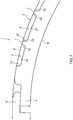
[1] 1 ist eine den schematischen Aufbau eines Dichtrings gemäß einer ersten Ausführungsform der vorliegenden Erfindung zeigende Seitenansicht einer Seite.[ 1 ] 1 Fig. 13 is a side view of one side showing the schematic structure of a seal ring according to a first embodiment of the present invention.
-
[2] 2 ist eine den schematischen Aufbau des Dichtrings gemäß der ersten Ausführungsform der vorliegenden Erfindung zeigende Frontansicht.[ 2 ] 2 Fig. 13 is a front view showing the schematic structure of the seal ring according to the first embodiment of the present invention.
-
[3] 3 ist eine den schematischen Aufbau des Dichtrings gemäß der ersten Ausführungsform der vorliegenden Erfindung zeigende Seitenansicht der anderen Seite.[ 3 ] 3 Fig. 13 is a side view of the other side showing the schematic structure of the seal ring according to the first embodiment of the present invention.
-
[4] 4 ist eine den schematischen Aufbau des Dichtrings gemäß der ersten Ausführungsform der vorliegenden Erfindung zeigende teilweise vergrößerte perspektivische Ansicht.[ 4th ] 4th Fig. 13 is a partially enlarged perspective view showing the schematic structure of the seal ring according to the first embodiment of the present invention.
-
[5] 5 ist ein teilweise vergrößerter Querschnitt des Dichtrings in einem Verwendungszustand, bei dem der Dichtring gemäß der ersten Ausführungsform der vorliegenden Erfindung an einem Gehäuse einer Hydraulikvorrichtung als Befestigungsobjekt und einer Welle befestigt ist, die in eine am Gehäuse als Durchgangsbohrung gebildete Wellenöffnung eingeschoben ist.[ 5 ] 5 Fig. 13 is a partially enlarged cross section of the seal ring in a state of use in which the seal ring according to the first embodiment of the present invention is attached to a housing of a hydraulic device as a fastening object and a shaft inserted into a shaft hole formed on the housing as a through hole.
-
[6] 6 ist ein teilweise vergrößerter Querschnitt des Dichtrings eines anderen Schnittes in einem Verwendungszustand, bei dem der Dichtring gemäß der ersten Ausführungsform der vorliegenden Erfindung an einem Gehäuse einer Hydraulikvorrichtung als Befestigungsobjekt und einer Welle befestigt ist, die in eine am Gehäuse als Durchgangsbohrung gebildete Wellenöffnung eingeschoben ist.[ 6th ] 6th Fig. 13 is a partially enlarged cross section of the seal ring of another section in a state of use in which the seal ring according to the first embodiment of the present invention is attached to a housing of a hydraulic device as a fastening object and a shaft inserted into a shaft hole formed on the housing as a through hole.
-
[7] 7 ist eine vergrößerte Seitenansicht des Dichtrings, die eine Abwandlung des Rippenabschnitts bei dem Dichtring gemäß der ersten Ausführungsform der vorliegenden Erfindung zeigt.[ 7th ] 7th Fig. 13 is an enlarged side view of the seal ring showing a modification of the rib portion in the seal ring according to the first embodiment of the present invention.
-
[8] 8 ist eine einen Teil der Seitenfläche einer Seite des Dichtrings, die den schematischen Aufbau des Dichtrings gemäß einer zweiten Ausführungsform der vorliegenden Erfindung zeigt, vergrößert zeigende teilweise vergrößerte Seitenansicht.[ 8th ] 8th Fig. 13 is a partially enlarged side view showing a part of the side surface of one side of the seal ring showing the schematic structure of the seal ring according to a second embodiment of the present invention.
-
[9] 9 ist eine teilweise vergrößerte Seitenansicht der Seitenfläche einer Seite des Dichtrings, die eine erste Abwandlung der Vertiefungen bei dem Dichtring gemäß der zweiten Ausführungsform der vorliegenden Erfindung zeigt.[ 9 ] 9 Fig. 13 is a partially enlarged side view of the side surface of one side of the seal ring showing a first modification of the recesses in the seal ring according to the second embodiment of the present invention.
-
[10] 10 ist eine teilweise vergrößerte Seitenansicht der Seitenfläche einer Seite des Dichtrings, die eine zweite Abwandlung der Vertiefungen bei dem Dichtring gemäß der zweiten Ausführungsform der vorliegenden Erfindung zeigt.[ 10 ] 10 Fig. 13 is a partially enlarged side view of the side surface of one side of the seal ring showing a second modification of the recesses in the seal ring according to the second embodiment of the present invention.
-
[11] 11 ist eine teilweise vergrößerte Seitenansicht der Seitenfläche einer Seite des Dichtrings, die eine dritte Abwandlung der Vertiefungen bei dem Dichtring gemäß der zweiten Ausführungsform der vorliegenden Erfindung zeigt.[ 11 ] 11 Fig. 13 is a partially enlarged side view of the side surface of one side of the seal ring showing a third modification of the recesses in the seal ring according to the second embodiment of the present invention.
[Formen zur Ausführung der vorliegenden Erfindung][Molds for Carrying Out the Present Invention]
Im Folgenden werden basierend auf den Figuren Ausführungsformen der vorliegenden Erfindung erläutert.
1 ist eine den schematischen Aufbau eines Dichtrings 1 gemäß einer ersten Ausführungsform der vorliegenden Erfindung zeigende Seitenansicht einer Seite. 2 ist eine Frontansicht, die den schematischen Aufbau des Dichtrings 1 zeigt. 3 ist eine den schematischen Aufbau des Dichtrings 1 zeigende Seitenansicht der anderen Seite. 4 ist ferner eine teilweise vergrößerte perspektivische Ansicht, die den schematischen Aufbau des Dichtrings 1 zeigt. Der Dichtring 1 gemäß der vorliegenden Ausführungsform ist eine Dichteinrichtung zum Abdichten eines ringförmigen Zwischenraums zwischen einer Welle und einer Wellenöffnung, in die die Welle eingeschoben wird, und wird bei einem Fahrzeug und einer Universalmaschine zum Abdichten eines Zwischenraumes zwischen einer Welle und einer z. B. an einem Gehäuse gebildeten Wellenöffnung verwendet, in die die Welle eingeschoben wird, wobei diese sich relativ zueinander drehen. Der Dichtring 1 wird in einer auf der Außenumfangsfläche einer Welle gebildeten Nut befestigt und verwendet, um z. B. bei einem Automatikgetriebe oder einem stufenlosen Getriebe die Hydraulik des Betriebsöls zu halten. Das Objekt (Befestigungsobjekt), auf das der Dichtring 1 gemäß der Ausführungsform der vorliegenden Erfindung angewendet wird, ist nicht auf das Vorstehende beschränkt.Embodiments of the present invention are explained below based on the figures.
1 is a schematic structure of a sealing ring 1 side view of a side according to a first embodiment of the present invention. 2 Fig. 13 is a front view showing the schematic structure of the seal ring 1 shows. 3 is a schematic structure of the sealing ring 1 showing side view of the other side. 4th Fig. 13 is also a partially enlarged perspective view showing the schematic structure of the seal ring 1 shows. The sealing ring 1 according to the present embodiment is a sealing device for sealing an annular gap between a shaft and a shaft opening into which the Shaft is inserted, and is used in a vehicle and a universal machine for sealing a gap between a shaft and a z. B. is used on a housing formed shaft opening into which the shaft is inserted, wherein these rotate relative to each other. The sealing ring 1 is fixed in a groove formed on the outer peripheral surface of a shaft and used to e.g. B. to keep the hydraulics of the operating oil in an automatic transmission or a continuously variable transmission. The object (fastening object) to which the sealing ring 1 is applied according to the embodiment of the present invention is not limited to the above.
Wie in 1 gezeigt, ist der Dichtring 1 um eine Achse x ringförmig, und umfasst eine zur Außenumfangsseite weisende, um die Achse x ringförmige Außenumfangsfläche 2 und eine Mehrzahl von in Umfangsrichtung zueinander beabstandet gebildeten, sich von der Außenumfangsfläche 2 zur Innenumfangsseite hin vertiefenden Vertiefungen 3. Die Mehrzahl der Vertiefungen 3 erstreckt sich in der Richtung der Achse x von einer Seitenfläche 4 bis zu einer eine andere Seitenfläche 5 nicht erreichenden Stelle. Die Außenumfangsfläche 2 weist zwischen der anderen Seitenfläche 5 und der die vorstehende andere Seitenfläche 5 nicht erreichenden Stelle eine Kontaktfläche 6 auf, bei der es sich um eine ringförmige Fläche handelt, und die Vertiefungen 3 zwischen den in Umfangsrichtung zueinander benachbarten Vertiefungen 3 weisen Rippenflächen 7 auf, bei denen es sich um Flächen handelt, die in der Richtung der Achse x zwischen der einen Seitenfläche 4 und der die vorstehende andere Seitenfläche 5 nicht erreichenden Stelle verlaufen.As in 1 shown is the sealing ring 1 around an axis x ring-shaped, and comprises one facing the outer circumferential side, around the axis x annular outer peripheral surface 2 and a plurality of circumferentially spaced from the outer circumferential surface 2 on the inner circumference side deepening depressions 3 . The majority of the wells 3 extends in the direction of the axis x from a side face 4th up to a different side surface 5 unreachable point. The outer peripheral surface 2 points between the other side face 5 and that of the above other side surface 5 not reach a contact surface 6th , which is an annular surface, and the depressions 3 between the recesses adjacent to one another in the circumferential direction 3 have rib surfaces 7th on, which are surfaces in the direction of the axis x between the one side surface 4th and that of the above other side surface 5 not reachable point.
Konkret stellt die Außenumfangsfläche 2 eine zur Außenumfangsseite weisende Fläche und eine als Gleitfläche gebildete Fläche dar, bei der im später beschriebenen Verwendungszustand eine Welle an die Innenumfangsfläche einer Wellenöffnung angedrückt wird, in die die Welle eingeschoben wird, und an dieser Innenumfangsfläche gleitet. Die Außenumfangsfläche 2 verläuft an einer zylinderförmigen Fläche oder einer im Wesentlichen zylinderförmigen Fläche mit der Achse x im Zentrum oder im Wesentlichen im Zentrum. Die eine Seitenfläche 4 ist eine Seitenfläche der Seite, auf die im später beschriebenen Verwendungszustand ein unter hohem Druck stehendes Betriebsöl wirkt und die im Folgenden auch als hochdruckseitige-Seitenfläche 4 bezeichnet wird. Die andere Seitenfläche 5 ist eine Seitenfläche der Seite, auf die im später beschriebenen Verwendungszustand ein unter niedrigem Druck stehendes Betriebsöl wirkt, die eine gegen die Nutseitenfläche der in der Welle gebildeten Nut gedrückte Seitenfläche darstellt und im Folgenden auch als niederdruckseitige-Seitenfläche 5 bezeichnet wird.Specifically, the outer peripheral surface represents 2 a surface facing the outer peripheral side and a surface formed as a sliding surface in which, in the state of use described later, a shaft is pressed against the inner peripheral surface of a shaft opening into which the shaft is inserted, and slides on this inner peripheral surface. The outer peripheral surface 2 runs on a cylindrical surface or a substantially cylindrical surface with the axis x in the center or substantially in the center. One side face 4th is a side surface of the side on which a high-pressure operating oil acts in the state of use described later, and which is hereinafter also referred to as the high-pressure side side surface 4th referred to as. The other side face 5 is a side surface of the side on which a low-pressure operating oil acts in the state of use described later, which is a side surface pressed against the groove side surface of the groove formed in the shaft and hereinafter also as a low-pressure side side surface 5 referred to as.
Bei dem Dichtring 1 ist die Form des Querschnitts der Fläche entlang der Achse x, wie in den 1 bis 3 gezeigt, rechteckig oder im Wesentlichen rechteckig, und der Dichtring 1 weist die vorstehend beschriebene Außenumfangsfläche 2, die hochdruckseitige-Seitenfläche 4 und die niederdruckseitige-Seitenfläche 5, sowie eine Innenumfangsfläche 8 auf, bei der es sich um eine zur Innenumfangsseite weisende Fläche handelt. Die hochdruckseitige-Seitenfläche 4 und die niederdruckseitige-Seitenfläche 5 sind z. B. ringförmige Flächen, die sich in einer ebenen Fläche oder einer im Wesentlichen ebenen Fläche orthogonal oder im Wesentlichen orthogonal zu der Achse x erstrecken und voneinander abgewandt sind. Ferner ist die Innenumfangsfläche 8 z. B. eine zylinderförmige Fläche oder eine im Wesentlichen zylinderförmige Fläche mit der Achse x im Zentrum oder im Wesentlichen im Zentrum und von der Außenumfangsfläche 2 abgewandt. Die hochdruckseitige-Seitenfläche 4 und die niederdruckseitige-Seitenfläche 5 erstrecken sich zwischen der Außenumfangsfläche 2 und der Innenumfangsfläche 8.With the sealing ring 1 is the shape of the cross-section of the surface along the axis x as in the 1 to 3 shown rectangular or substantially rectangular, and the sealing ring 1 has the outer peripheral surface described above 2 , the high-pressure side face 4th and the low pressure side side surface 5 , and an inner peripheral surface 8th which is a surface facing the inner peripheral side. The side surface on the high pressure side 4th and the low pressure side side surface 5 are z. B. annular surfaces that are in a flat surface or a substantially flat surface orthogonal or substantially orthogonal to the axis x extend and are facing away from each other. Further is the inner peripheral surface 8th z. B. a cylindrical surface or a substantially cylindrical surface with the axis x in the center or substantially in the center and from the outer peripheral surface 2 turned away. The side surface on the high pressure side 4th and the low pressure side side surface 5 extend between the outer peripheral surface 2 and the inner peripheral surface 8th .
Wie in den 1, 2 gezeigt, sind in dem Abschnitt der Außenumfangsseite des Dichtrings 1 mehrere Vertiefungen 3 in Umfangsrichtung nebeneinander liegend gebildet, bei denen es sich um von der Außenumfangsfläche 2 zur Innenumfangsseite vertiefte Abschnitte handelt. Die Vertiefungen 3 sind z. B. jeweils identisch und um die Achse x in gleichen Winkelabständen oder im Wesentlichen gleichen Winkelabständen gebildet. Die jeweiligen Vertiefungen 3 erstrecken sich in der Richtung der Achse x von der hochdruckseitigen-Seitenfläche 4 bis zu einer die niederdruckseitige-Seitenfläche 5 nicht erreichende Zwischenposition der Breite des Dichtrings 1 in der Richtung der Achse x (Nutseitenflächenposition L (vgl. 2)). Wie in 2 gezeigt, haben die Vertiefungen 3, von der Außenumfangsseite aus radial betrachtet, eine rechteckige oder im Wesentlichen rechteckige Form.As in the 1 , 2 shown are in the portion of the outer peripheral side of the sealing ring 1 several wells 3 formed lying next to one another in the circumferential direction, which are from the outer peripheral surface 2 to the inner peripheral side is recessed sections. The depressions 3 are z. B. each identical and around the axis x formed at equal angular intervals or substantially equal angular intervals. The respective wells 3 extend in the direction of the axis x from the high-pressure side side surface 4th up to the side surface on the low pressure side 5 not reaching intermediate position of the width of the sealing ring 1 in the direction of the axis x (Groove side surface position L. (see. 2 )). As in 2 shown have the depressions 3 , viewed radially from the outer circumference side, a rectangular or substantially rectangular shape.
Konkret sind die Vertiefungen 3, wie in 4 gezeigt, ausgehend von der hochdruckseitigen-Seitenfläche 4 zur hochdruckseitigen-Seitenfläche 4 offen und ferner ausgehend von der Außenumfangsfläche 2 zur Außenumfangsseite offen, und an beiden Enden in Umfangsrichtung und an einem Endabschnitt auf der Seite der niederdruckseitige-Seitenfläche 5 geschlossen. Die Vertiefungen 3 weisen z. B., wie in 4 gezeigt, eine Bodenfläche 31, die eine zur Außenumfangsseite weisende Fläche ist, eine Vorderwandfläche 32 und eine Rückwandfläche 33, die von beiden Umfangsenden der Bodenfläche 31 in Umfangsrichtung zur Außenumfangsseite hin verlaufenden Flächen sind, , sowie eine Querwandfläche 34 auf, die eine vom Ende der Seite der niederdruckseitigen Seitenfläche 5 der Bodenfläche 31 zur Außenumfangsseite hin verlaufende Fläche ist. Die Bodenfläche 31 ist eine gewölbte Fläche, die sich an einer zylinderförmigen Fläche oder einer im Wesentlichen zylinderförmigen Fläche mit der Achse x im Zentrum oder im Wesentlichen im Zentrum erstreckt. Die Bodenfläche 31 kann auch eine ebene Fläche sein. Die Vorderwandfläche 32 und die Rückwandfläche 33 verlaufen von der Achse x auf einer zu der Achse x parallel oder im Wesentlichen parallel verlaufenden ebenen Fläche oder im Wesentlichen ebenen Fläche, wobei die Vorderwandfläche 32 und die Rückwandfläche 33 zwischen der Bodenfläche 31 und der Außenumfangsfläche 2 (Rippenfläche 7) verlaufen. Die Vorderwandfläche 32 ist in dem im später beschriebenen Verwendungszustand in der Drehrichtung des Dichtrings (Dichtring-Drehrichtung (vgl. 1, 4)) auf der Vorderseite positioniert, und die Rückwandfläche 33 ist in der Dichtring-Drehrichtung auf der Rückseite positioniert. Die Querwandfläche 34 verläuft in einer zu der Achse x orthogonalen oder im Wesentlichen orthogonalen ebenen Fläche oder im Wesentlichen ebenen Fläche, wobei die Vorderwandfläche 32 und die Rückwandfläche 33 zwischen der Bodenfläche 31 und der Außenumfangsfläche 2 (Kontaktfläche 6) verläuft. Auf diese Weise sind die Vertiefungen 3 durch die Bodenfläche 31, die Vorderwandfläche 32, die Rückwandfläche 33 und die Querwandfläche 34 begrenzt, und bilden im Inneren einen im Wesentlichen rechteckplattenförmigen Raum.The recesses are specific 3 , as in 4th shown, starting from the high-pressure side side surface 4th to the side face on the high pressure side 4th open and also starting from the outer peripheral surface 2 open to the outer peripheral side, and at both ends in the circumferential direction and at an end portion on the side of the low-pressure side side surface 5 closed. The depressions 3 show z. B., as in 4th shown a floor area 31 , which is a surface facing the outer peripheral side, a front wall surface 32 and a back panel 33 from both peripheral ends of the floor surface 31 in the circumferential direction towards the outer circumferential side are surfaces, as well as a transverse wall surface 34 on the one from the end of the side of the low-pressure side face 5 the floor area 31 to the outer circumferential side running surface is. The floor area 31 is a curved surface that adapts to a cylindrical surface or a substantially cylindrical surface with the axis x extends in the center or substantially in the center. The floor area 31 can also be a flat surface. The front wall surface 32 and the back panel 33 run off the axis x on one to the axis x parallel or substantially parallel flat surface or substantially flat surface, wherein the front wall surface 32 and the back panel 33 between the floor area 31 and the outer peripheral surface 2 (Rib surface 7th ) run. The front wall surface 32 is in the condition of use described later in the direction of rotation of the sealing ring (sealing ring rotation direction (cf. 1 , 4th )) positioned on the front, and the back panel 33 is positioned on the back in the direction of rotation of the sealing ring. The transverse wall surface 34 runs in one to the axis x orthogonal or substantially orthogonal planar surface or substantially planar surface, wherein the front wall surface 32 and the back panel 33 between the floor area 31 and the outer peripheral surface 2 (Contact area 6th ) runs. This is how the pits are 3 through the floor area 31 , the front wall surface 32 , the back panel 33 and the transverse wall surface 34 limited, and form inside a substantially rectangular plate-shaped space.
Zwischen den in Umfangsrichtung zueinander benachbarten Vertiefungen 3 sind Rippenabschnitte 35 gebildet, die von der Bodenfläche 31 bis zur Außenumfangsfläche 2 (Rippenfläche 7) zur Außenumfangsseite vorstehende Abschnitte sind, wobei die Rippenabschnitte 35 parallel oder im Wesentlichen parallel zur Achse x verlaufen, und durch die Vorderwandfläche 32 und die Rückwandfläche 33, die voneinander abgewandt sind, die Rippenfläche 7 sowie die hochdruckseitige-Seitenfläche 4 begrenzt sind. Ferner sind zwischen den jeweiligen Vertiefungen 3 und der niederdruckseitigen-Seitenfläche 5 Kontaktvorsprünge 36 gebildet, die von der Bodenfläche 31 bis zur Außenumfangsfläche 2 (Kontaktfläche 6) zur Außenumfangsseite vorstehende ringförmige Abschnitte sind, wobei die Kontaktvorsprünge 36 durch die niederdruckseitige-Seitenfläche 5, die Querwandfläche 34 und die Kontaktfläche 6 begrenzt sind.Between the recesses adjacent to one another in the circumferential direction 3 are rib sections 35 formed by the floor area 31 up to the outer peripheral surface 2 (Rib surface 7th ) are portions protruding to the outer circumference side, the rib portions 35 parallel or substantially parallel to the axis x run, and through the front panel 32 and the back panel 33 facing away from each other, the rib surface 7th as well as the side surface on the high pressure side 4th are limited. Furthermore, between the respective depressions 3 and the low pressure side side surface 5 Contact protrusions 36 formed by the floor area 31 up to the outer peripheral surface 2 (Contact area 6th ) to the outer circumferential side protruding annular sections, wherein the contact projections 36 through the side face on the low pressure side 5 , the transverse wall surface 34 and the contact area 6th are limited.
Die Außenumfangsfläche 2 weist, wie vorstehend beschrieben, eine einzige Kontaktfläche 6 und eine Mehrzahl von Rippenflächen 7 auf. Wie in 4 gezeigt, ist die Kontaktfläche 6 konkret eine sich in der Richtung der Achse x zwischen der niederdruckseitigen-Seitenfläche 5 und der Nutseitenflächenposition L erstreckende zylinderförmige Fläche oder im Wesentlichen zylinderförmige Fläche mit der Achse x im Zentrum oder im Wesentlichen im Zentrum. Ferner sind die jeweiligen Rippenflächen 7 im Wesentlichen rechteckige Flächen, die auf einer zylinderförmigen Fläche oder einer im Wesentlichen zylinderförmigen Fläche mit der Achse x im Zentrum oder im Wesentlichen im Zentrum parallel oder im Wesentlichen parallel zur Achse x verlaufen. Die Außenumfangsfläche 2 kommt im später beschriebenen Verwendungszustand mit der Innenumfangsfläche der Wellenöffnung in Kontakt und stellt eine an der Innenumfangsfläche gleitende Gleitfläche dar. Das heißt, die Kontaktfläche 6 und die Rippenfläche 7 fungieren im später beschriebenen Verwendungszustand als eine Gleitfläche. Im später beschriebenen Verwendungszustand ist zur Reduzierung des auf den Dichtring 1 wirkenden Gleitwiderstands eine geringe Breite der Kontaktfläche 6 in der Richtung der Achse x bevorzugt.The outer peripheral surface 2 as described above, has a single contact area 6th and a plurality of rib surfaces 7th on. As in 4th shown is the contact area 6th specifically one is in the direction of the axis x between the low-pressure side face 5 and the groove side surface position L. extending cylindrical surface or substantially cylindrical surface with the axis x in the center or essentially in the center. Furthermore, the respective rib surfaces 7th substantially rectangular surfaces which are on a cylindrical surface or a substantially cylindrical surface with the axis x in the center or substantially in the center parallel or substantially parallel to the axis x run away. The outer peripheral surface 2 comes into contact with the inner peripheral surface of the shaft hole in the state of use described later, and constitutes a sliding surface sliding on the inner peripheral surface. That is, the contact surface 6th and the rib surface 7th function as a sliding surface in the state of use described later. In the state of use described later is to reduce the on the sealing ring 1 acting sliding resistance a small width of the contact surface 6th in the direction of the axis x prefers.
Der Dichtring 1 wird aus einem Harzmaterial wie Polyetheretherketon (PEEK), Polyphenylensulfid (PPS) oder Polytetrafluorethylen (PTFE) ausgebildet. Die Umfangslänge der Außenumfangsfläche 2 (Kontaktabschnitt 6) des Dichtrings 1 ist kürzer als die Umfangslänge der Innenumfangsfläche der Wellenöffnung, in die die Welle eingeschoben wird, und weist kein Übermaß gegenüber der Wellenöffnung auf. Daher gelangt die Außenumfangsfläche 2 des Dichtrings 1 in einem Zustand, in dem im Verwendungszustand kein Flüssigkeitsdruck auf den Dichtring 1 ausgeübt ist, in einen von der Innenumfangsfläche der Wellenöffnung beabstandeten Zustand.The sealing ring 1 is formed from a resin material such as polyetheretherketone (PEEK), polyphenylene sulfide (PPS), or polytetrafluoroethylene (PTFE). The circumferential length of the outer peripheral surface 2 (Contact section 6th ) of the sealing ring 1 is shorter than the circumferential length of the inner circumferential surface of the shaft opening into which the shaft is inserted, and has no oversize with respect to the shaft opening. Hence, the outer peripheral surface comes 2 of the sealing ring 1 in a state in which there is no liquid pressure on the sealing ring in the state of use 1 is exerted in a state spaced from the inner peripheral surface of the shaft opening.
Der Dichtring 1 ist ferner nicht endlos, sondern es ist an einer Stelle in Umfangsrichtung, wie in den 1 bis 3 gezeigt, ein Auflageabschnitt 9 vorgesehen. Der Auflageabschnitt 9 hat einen bekannten Aufbau, der auch bei einer Änderung der Umfangslänge des Dichtrings 1 aufgrund einer Wärmeausdehnung oder einer Wärmeschrumpfung des Dichtrings 1 eine stabile Beibehaltung der Abdichtfähigkeit ermöglicht. Als Struktur des Auflageabschnitts 9 gibt es z. B. eine so genannte spezielle Stufenschnittstruktur, bei der dieser von der Seite sowohl der Außenumfangsfläche 2 als auch der beiden Seitenflächen 4, 5 aus betrachtet stufenförmig abgeschnitten ist, sowie eine Geradschnittstruktur, eine Schrägschnittstruktur, eine Stufenschnittstruktur usw. Ferner kann für den Fall, dass als Material des Dichtrings 1 ein wenig elastisches Material (PTFE usw.) verwendet wird, an dem Dichtring 1 der Auflageabschnitt 9 nicht vorgesehen und der Dichtring 1 endlos gebildet werden.The sealing ring 1 is also not endless, but is at one point in the circumferential direction, as in 1 to 3 shown, a support section 9 intended. The support section 9 has a known structure that also changes when the circumferential length of the sealing ring is changed 1 due to thermal expansion or shrinkage of the sealing ring 1 enables stable retention of the sealability. As the structure of the support section 9 is there e.g. B. a so-called special step-cut structure, in which this from the side and the outer peripheral surface 2 as well as the two side surfaces 4th , 5 is cut off in a stepped manner, as well as a straight cut structure, an oblique cut structure, a stepped cut structure, etc. Furthermore, in the event that as the material of the sealing ring 1 a little elastic material (PTFE etc.) is used on the sealing ring 1 the support section 9 not provided and the sealing ring 1 be formed endlessly.
Als Nächstes wird die Wirkungsweise des Dichtrings 1 mit dem vorstehenden Aufbau erläutert.Next is how the sealing ring works 1 with the above structure explained.
5 ist ein teilweise vergrößerter Querschnitt des Dichtrings 1 in einem Verwendungszustand, bei dem der Dichtring 1 an einem Gehäuse 101 einer Hydraulikvorrichtung 100 als Befestigungsobjekt und einer Welle 110 befestigt ist, die in eine an dem Gehäuse 101 als Durchgangsbohrung gebildete Wellenöffnung 102 eingeschoben ist. Die Welle 110 ist relativ zu dem Gehäuse 101 drehbar, und auf der Außenumfangsfläche 111 der Welle 110 ist eine zur Mitte hin vertiefte ringförmige Nut 112 gebildet. Die Nut 112 hat eine rechteckige oder im Wesentlichen rechteckige Querschnittsform und ist durch ebene Seitenflächen 113, 114 und eine Bodenfläche 115 begrenzt. Bei der Hydraulikvorrichtung 100 ist zwischen der Innenumfangsfläche 103 der Wellenöffnung 102 und der Außenumfangsfläche 111 der Welle 110 ein ringförmiger Raum gebildet und an der Welle 110 und dem Gehäuse 101 ist eine nicht dargestellte mit Betriebsöl gefüllte Hydraulikleitung gebildet. Der Dichtring 1 wird in der Nut 112 befestigt und dichtet einen Zwischenraum G zwischen der Welle 110 und der Wellenöffnung 102 ab, um einen Hydraulikverlust des Betriebsöls in der Hydraulikleitung zu verhindern. In 5 ist auf der rechten Seite der Nut 112 der Hydraulikfluss, und die Seitenfläche 113 auf der linken Seite der Nut 112 fungiert als Kontaktseitenfläche, gegen die der Dichtring 1 gedrückt wird, wobei sich auf der rechten Seite (H-Seite) der Nut 112 ein Hochdruck und auf der linken Seite (L-Seite) der Nut 112 ein Niederdruck ergibt. Der Dichtring 1 wird in der Nut 112 derart befestigt, dass die niederdruckseitige-Seitenfläche 5 der Kontaktseitenfläche 113 der Nut 112 gegenüberliegt. 5 Fig. 13 is a partially enlarged cross section of the seal ring 1 in a state of use in which the sealing ring 1 on a housing 101 a hydraulic device 100 as a fastening object and a shaft 110 is attached in a to the housing 101 Shaft opening formed as a through hole 102 is inserted. The wave 110 is relative to the housing 101 rotatable, and on the outer peripheral surface 111 the wave 110 is an annular groove deepened towards the center 112 educated. The groove 112 has a rectangular or substantially rectangular cross-sectional shape and is characterized by flat side surfaces 113 , 114 and a floor area 115 limited. With the hydraulic device 100 is between the inner peripheral surface 103 the shaft opening 102 and the outer peripheral surface 111 the wave 110 an annular space is formed and attached to the shaft 110 and the case 101 a hydraulic line, not shown, filled with operating oil is formed. The sealing ring 1 is in the groove 112 fixes and seals a gap G between the wave 110 and the shaft opening 102 to prevent hydraulic loss of the operating oil in the hydraulic line. In 5 is on the right side of the groove 112 the hydraulic flow, and the side face 113 on the left side of the groove 112 acts as the contact side surface against which the sealing ring 1 is pressed, being on the right-hand side (H-side) of the groove 112 a high pressure and on the left side (L-side) of the groove 112 results in a low pressure. The sealing ring 1 is in the groove 112 attached so that the low-pressure side side face 5 the contact face 113 the groove 112 opposite.
Wird in die Hydraulikleitung Betriebsöl eingeleitet, entsteht in der Hydraulikleitung ein Hochdruck und die Außenumfangfläche 2 des Dichtrings 1 und die niederdruckseitige-Seitenfläche 5 werden jeweils gegen die Innenumfangsfläche 103 der Wellenöffnung 102 und die Kontaktseitenfläche 113 der Nut 112 gedrückt. Hierdurch wird die Hydraulikleitung an dem ringförmigen Zwischenraum G abgedichtet und ein Halten der Hydraulik angestrebt. Dabei bildet sich zwischen den jeweiligen Vertiefungen 3 und der Innenumfangsfläche 103 der Wellenöffnung 102 ein zur Hochdruckseite (H) geöffneter Raum S, und das Hochdruckbetriebsöl dringt in den Raum S ein. Wie in 5 gezeigt, werden dann Kräfte (Pfeil PL in 5) aufgrund der Druckkraft des Hochdruckbetriebsöls auf die Innenumfangsfläche 8 ausgeübt, und ferner werden Kräfte (Pfeil PU in 5) aufgrund der Druckkraft des Hochdruckbetriebsöls auf die Bodenfläche 31 der Vertiefungen 3 ausgeübt. Die Vertiefungen 3 verlaufen von der hochdruckseitigen-Seitenfläche 4 bis zur im Bereich der Breite des Dichtrings 1 liegenden Stelle (Querseitenflächenposition L), wobei ein Großteil der auf die Innenumfangsfläche 8 ausgeübten Kräfte PL durch die auf die Bodenfläche 31 der Vertiefungen 3 ausgeübten Kräfte PU kompensiert wird. Hierdurch werden die auf die hochdruckseitige-Seitenfläche 4 des Dichtrings 1 ausgeübten Kräfte (Pfeil PS in 5) aufgrund der Druckkraft des Hochdruckbetriebsöls größer als die Kräfte (PL-PU), die die Außenumfangsfläche 2 (Kontaktfläche 6 und Rippenfläche 7) an die Innenumfangsfläche 103 der Wellenöffnung 102 drücken. Wenn sich die Welle 110 dreht, dreht sich daher der Dichtring 1 zusammen mit der Welle 110, und die Außenumfangsfläche 2 des Dichtrings 1 gleitet gegenüber der Innenumfangsfläche 103 der Wellenöffnung 102. Ferner bleibt die niederdruckseitige-Seitenfläche 5 des Dichtrings 1 mit der Kontaktfläche 113 der Nut 112 in Kontakt.If operating oil is introduced into the hydraulic line, high pressure and the outer circumferential surface are created in the hydraulic line 2 of the sealing ring 1 and the low pressure side side surface 5 are each against the inner peripheral surface 103 the shaft opening 102 and the contact face 113 the groove 112 pressed. As a result, the hydraulic line is attached to the annular space G sealed and aimed at maintaining the hydraulics. This forms between the respective depressions 3 and the inner peripheral surface 103 the shaft opening 102 a space open to the high pressure side (H) S. , and the high-pressure operating oil enters the room S. one. As in 5 then forces (arrow PL in 5 ) due to the pressing force of the high-pressure operating oil on the inner peripheral surface 8th exerted, and further forces (arrow PU in 5 ) due to the pressing force of the high pressure operating oil on the floor surface 31 of the wells 3 exercised. The depressions 3 run from the high-pressure side side surface 4th up to in the range of the width of the sealing ring 1 lying position (transverse side surface position L. ), with much of the on the inner peripheral surface 8th forces PL exerted by the forces acting on the floor surface 31 of the wells 3 exerted forces PU is compensated. As a result, the side surface on the high-pressure side 4th of the sealing ring 1 forces exerted (arrow PS in 5 ) due to the pressure force of the high-pressure operating oil is greater than the forces (PL-PU) that the outer peripheral surface 2 (Contact area 6th and rib surface 7th ) to the inner peripheral surface 103 the shaft opening 102 to press. When the wave 110 rotates, therefore the sealing ring rotates 1 along with the wave 110 , and the outer peripheral surface 2 of the sealing ring 1 slides against the inner peripheral surface 103 the shaft opening 102 . Furthermore, the side face on the low pressure side remains 5 of the sealing ring 1 with the contact surface 113 the groove 112 in contact.
Auf diese Weise gleitet der Dichtring 1 mit seiner Außenumfangsfläche 2 (Kontaktfläche 6 und Rippenfläche 7) gegenüber der Hydraulikvorrichtung 100 (Innenumfangsfläche 103 der Wellenöffnung 102) als Befestigungsobjekt, ohne dass sich je nach der diametralen Breite des Zwischenraums G zwischen der Wellenöffnung 102 und der Welle 110, einer Exzentrik der Welle 110, usw. bei der Hydraulikvorrichtung 100 als Befestigungsobjekt die Kontaktfläche mit der Kontaktseitenfläche 113 der Nut 112 verändert. Dadurch ändert sich die Abdichtfähigkeit des Dichtrings 1 nicht je nach Aufbau der Hydraulikvorrichtung 100 als Befestigungsobjekt.In this way the sealing ring slides 1 with its outer peripheral surface 2 (Contact area 6th and rib surface 7th ) opposite the hydraulic device 100 (Inner peripheral surface 103 the shaft opening 102 ) as a fastening object, without depending on the diametrical width of the gap G between the shaft opening 102 and the wave 110 , an eccentricity of the shaft 110 , etc. in the hydraulic device 100 the contact surface with the contact side surface as the fastening object 113 the groove 112 changed. This changes the sealing ability of the sealing ring 1 not depending on the structure of the hydraulic device 100 as a fastening object.
Ferner steht der Dichtring 1, wie in 6 gezeigt, im Verwendungszustand in dem Bereich, in dem ein Rippenabschnitt 35 gebildet ist, insgesamt zwischen den beiden Seitenflächen 4, 5 mit der Innenumfangsfläche 103 der Wellenöffnung 102 in Kontakt. Das heißt, auch in dem Bereich, in dem die Vertiefungen 3 gebildet sind, steht die Rippenfläche 7 des Rippenabschnitts 35 mit der Innenumfangsfläche 103 der Wellenöffnung 102 in Kontakt. Daher kann eine Neigung der Kontaktfläche 6 gegenüber der Innenumfangsfläche 103 der Wellenöffnung 102 verhindert und der Kontaktzustand der Kontaktfläche 6 mit der Innenumfangsfläche 103 der Wellenöffnung 102 stabilisiert werden. Ferner kann ebenso eine Neigung der niederdruckseitigen-Seitenfläche 5 gegenüber der Seitenfläche 113 der Nut 112 verhindert und der Kontaktzustand der niederdruckseitigen-Seitenfläche 5 mit der Seitenfläche 113 der Nut 112 stabilisiert werden. Hierdurch kann die Abdichtfähigkeit des Dichtrings 1 stabilisiert werden. Ferner kann hierdurch unter Aufrechterhaltung der Stabilität der Abdichtfähigkeit des Dichtrings 1 die Breite der Kontaktfläche 6 weiter verkleinert werden.The sealing ring is also in place 1 , as in 6th shown, in the state of use in the area where a rib portion 35 is formed, a total of between the two side surfaces 4th , 5 with the inner peripheral surface 103 the shaft opening 102 in contact. That is, even in the area where the depressions 3 are formed, is the rib surface 7th of the rib section 35 with the inner peripheral surface 103 the shaft opening 102 in contact. Therefore, there may be an inclination of the contact surface 6th opposite the inner peripheral surface 103 the shaft opening 102 prevented and the contact state of the contact surface 6th with the inner peripheral surface 103 the shaft opening 102 be stabilized. Furthermore, an inclination of the low-pressure side side surface can also be 5 opposite the side face 113 the groove 112 prevented and the contact state of the low pressure side side face 5 with the side face 113 the groove 112 be stabilized. This can reduce the sealing ability of the sealing ring 1 be stabilized. Furthermore, while maintaining the stability of the sealing ability of the sealing ring 1 the width of the contact area 6th can be further reduced.
Ferner ermöglichen die Vertiefungen 3 eine Reduzierung der Kontaktfläche des Dichtrings 1 mit der Innenumfangsfläche 103 der Wellenöffnung 102 und eine Reduzierung des Gleitwiderstands der Wellenöffnung 102 gegenüber dem Dichtring 1.Furthermore, the recesses allow 3 a reduction in the contact area of the sealing ring 1 with the inner peripheral surface 103 the shaft opening 102 and a reduction in the sliding resistance of the shaft opening 102 opposite the sealing ring 1 .
Da bei dem Dichtring 1 der Gleitwiderstand der Wellenöffnung 102 gegenüber dem Dichtring 1, wie vorstehend beschrieben reduziert werden kann, kann ferner eine Wärmebildung an dem Gleitabschnitt während der Verwendung unterdrückt werden, sodass der Dichtring 1 unter noch höheren PV-Bedingungen verwendet werden kann. Ferner kann der Dichtring 1 auch bei einer weichen Welle 110 verwendet werden.As with the sealing ring 1 the sliding resistance of the shaft opening 102 opposite the sealing ring 1 Further, as described above, heat generation at the sliding portion during use can be suppressed, so that the seal ring 1 can be used under even higher PV conditions. Furthermore, the sealing ring 1 even with a soft wave 110 be used.
Auf diese Weise kann nach dem Dichtring 1 gemäß der ersten Ausführungsform der vorliegenden Erfindung dafür gesorgt werden, dass sich die Abdichtfähigkeit des Dichtrings 1 je nach Struktur des Befestigungsobjekts nicht verändert.In this way, after the sealing ring 1 According to the first embodiment of the present invention, it can be ensured that the sealing ability of the sealing ring 1 not changed depending on the structure of the fastening object.
Wie vorstehend beschrieben, dreht sich der Dichtring 1 im Verwendungszustand zusammen mit der Welle 110, wobei die Außenumfangsfläche 2 gegenüber der Innenumfangsfläche 103 der Wellenöffnung 102 gleitet und sich die Vertiefungen 3 entlang der Innenumfangsfläche 103 der Wellenöffnung 102 bewegen. Daher bewegt sich das in die Vertiefungen 3 eingedrungene Betriebsöl zusammen mit den Vertiefungen 3 entlang der Innenumfangsfläche 103 der Wellenöffnung 102, wobei durch die Rippenabschnitte 35 ein dynamischer Druckeffekt des Betriebsöls entsteht, sodass sich zwischen den Rippenflächen 7 und der Innenumfangsfläche 103 der Wellenöffnung 102 ein Ölfilm bildet. Hierdurch kann der auf den Dichtring 1 wirkende Gleitwiderstand reduziert werden. Unter Berücksichtigung des dynamischen Druckeffekts ist eine in der Drehrichtung des Dichtrings 1 glatte Form der Rippenabschnitte 35 bevorzugt. Beispielsweise kann dadurch, dass die Rippenabschnitte 35 wie bei der in 7 gezeigten Abwandlung eines Rippenabschnitts 35 eine eckenlose Form haben, durch den dynamischen Druckeffekt die Dicke des auf der Rippenfläche 7 gebildeten Betriebsölfilms vergrößert werden. Konkret sind bei den Rippenabschnitten 35 gemäß der Abwandlung die Bodenfläche 31 und die Vorderwandfläche 32 der Vertiefungen 3 durch eine gewölbte Fläche glatt verbunden, die Vorderwandfläche 32 und die Rippenfläche 7 durch eine gewölbte Fläche glatt verbunden, die Rippenfläche 7 und die Rückwandfläche 33 durch eine gewölbte Fläche glatt verbunden, sowie die Rückwandfläche 33 und die Bodenfläche 31 durch eine gewölbte Fläche glatt verbunden. Die Bodenfläche 31 kann mit der Vorderwandfläche 32 und der Rückwandfläche 33 auch durch eine nicht gewölbte Fläche, sondern durch eine ebene Fläche oder eine Mehrzahl von ebenen Flächen, die schräg verläuft, glatt verbunden sein, und ebenso kann die Rippenfläche 7 mit der Vorderwandfläche 32 und der Rückwandfläche 33 durch eine nicht gewölbte Fläche, sondern durch eine ebene Fläche oder eine Mehrzahl von ebenen Flächen, die schräg verläuft, glatt verbunden werden.As described above, the sealing ring rotates 1 when used together with the shaft 110 , where the outer peripheral surface 2 opposite the inner peripheral surface 103 the shaft opening 102 slides and deepens the indentations 3 along the inner peripheral surface 103 the shaft opening 102 move. Hence that moves into the pits 3 penetrated operating oil together with the depressions 3 along the inner peripheral surface 103 the shaft opening 102 , being through the rib sections 35 a dynamic pressure effect of the operating oil is created, so that between the rib surfaces 7th and the inner peripheral surface 103 the shaft opening 102 forms an oil film. This allows the on the sealing ring 1 acting sliding resistance can be reduced. Taking into account the dynamic pressure effect, one is in the direction of rotation of the sealing ring 1 smooth shape of the rib sections 35 prefers. For example, in that the rib sections 35 as with the in 7th shown modification of a rib section 35 have a cornerless shape, due to the dynamic pressure effect, the thickness of the on the rib surface 7th formed operating oil film can be enlarged. Specifically are the rib sections 35 according to the modification the floor area 31 and the front panel 32 of the wells 3 Smoothly connected by a curved surface, the front wall surface 32 and the rib surface 7th Smoothly connected by a curved surface, the rib surface 7th and the back panel 33 Smoothly connected by a curved surface, as well as the rear wall surface 33 and the floor area 31 smoothly connected by a curved surface. The floor area 31 can with the front wall surface 32 and the back panel 33 can also be smoothly connected by a non-curved surface, but by a flat surface or a plurality of flat surfaces running obliquely, and the rib surface may also be connected 7th with the front wall surface 32 and the back panel 33 be smoothly connected by a non-curved surface, but by a flat surface or a plurality of flat surfaces running at an angle.
Als Nächstes wird ein Dichtring 10 gemäß einer zweiten Ausführungsform der vorliegenden Erfindung erläutert. 8 ist eine einen Teil der Seitenfläche einer Seite des Dichtrings 10 vergrößernd zeigende teilweise vergrößerte Seitenansicht, die den schematischen Aufbau des Dichtrings 8 zeigt. Der Dichtring 10 gemäß der zweiten Ausführungsform der vorliegenden Erfindung unterscheidet sich von dem vorstehend beschriebenen Dichtring 1 gemäß der ersten Ausführungsform der vorliegenden Erfindung im Aufbau der Vertiefungen und der Rippenabschnitte. Im Folgenden werden bezüglich des Dichtrings 10 gemäß der zweiten Ausführungsform der vorliegenden Erfindung Strukturen mit gleichen oder gleichartigen Funktionen wie bei dem Dichtring 1 gemäß der ersten Ausführungsform der vorliegenden Erfindung mit den gleichen Bezugszeichen versehen und deren Erläuterung wird ausgelassen, wobei unterschiedliche Strukturen erläutert werden.Next is a sealing ring 10 explained according to a second embodiment of the present invention. 8th is a part of the side surface of one side of the seal ring 10 partially enlarged side view showing the schematic structure of the sealing ring 8th shows. The sealing ring 10 according to the second embodiment of the present invention is different from the sealing ring described above 1 according to the first embodiment of the present invention in the structure of the recesses and the rib portions. In the following, regarding the sealing ring 10 According to the second embodiment of the present invention, structures having the same or similar functions as the sealing ring 1 according to the first embodiment of the present invention are given the same reference numerals and the explanation thereof is omitted, and different structures are explained.
Wie in 8 gezeigt, weist der Dichtring 10 eine Mehrzahl von Vertiefungen 40 auf, die ebenso wie die Vertiefungen 3 des Dichtrings 1 in Umfangsrichtung nebeneinander liegend gebildet ist, wobei zwischen zueinander benachbarten Vertiefungen 40 die Rippenfläche 7 aufweisende Rippenabschnitte 46 gebildet sind. Die Bodenfläche 41 jeder Vertiefung 40 ist von beiden Enden der Vertiefung 40 in Umfangsrichtung absinkend zur Innenumfangsseite vertieft. Konkret ist die Bodenfläche 41 aus einem Bodenabschnitt 42, einem Vorderwandabschnitt 43 und einem Rückwandabschnitt 44 ausgebildet, wobei es sich bei dem Bodenabschnitt 42 um eine zur Innenumfangsseite konvex gekrümmte gewölbte Fläche, und bei dem Vorderwandabschnitt 43 und dem Rückwandabschnitt 44 um zur Außenumfangsseite konvex gekrümmte gewölbte Flächen handelt. Der Vorderwandabschnitt 43 ist am Ende der Innenumfangsseite glatt mit dem Bodenabschnitt 42 verbunden, und ferner ist der Rückwandabschnitt 44 am Ende der Innenumfangsseite glatt auf der dem Vorderwandabschnitt 43 gegenüberliegenden Seite mit dem Bodenabschnitt 42 verbunden. Auf diese Weise ist die Bodenfläche 41 jeder Vertiefung 40 als glatte gewölbte Fläche gebildet, und durch den Vorderwandabschnitt 43, den Bodenabschnitt 42 und den Rückwandabschnitt 44 begrenzt. Ferner ist bei jeder Vertiefung 40 eine Querwandfläche 45 gebildet, die vom Rand der Seite des Vorderwandabschnitts 43, des Bodenabschnitts 42 und der niederdruckseitigen-Seitenfläche 5 des Rückwandabschnitts 44 bis zur Kontaktfläche 6 verläuft und eine zur Achse x orthogonale oder im Wesentlichen orthogonale ebene Fläche oder im Wesentlichen ebene Fläche ist. Durch die Querwandfläche 45, die Kontaktfläche 6 und die niederdruckseitige-Seitenfläche 5 ist ein ringförmiger Kontaktvorsprung 36 begrenzt. Ein Rippenabschnitt 46 ist durch den Vorderwandabschnitt 43 und den Rückwandabschnitt 44, die in Umfangsrichtung voneinander abgewandt sind, sowie die zwischen dem Vorderwandabschnitt 43 und dem Rückwandabschnitt 44 verlaufende Rippenfläche 7 begrenzt.As in 8th shown, the sealing ring 10 a plurality of pits 40 on that as well as the depressions 3 of the sealing ring 1 is formed lying next to one another in the circumferential direction, wherein between mutually adjacent depressions 40 the rib surface 7th having rib sections 46 are formed. The floor area 41 each well 40 is from both ends of the recess 40 recessed in the circumferential direction decreasing to the inner circumferential side. The floor area is concrete 41 from a floor section 42 , a front wall section 43 and a rear wall section 44 formed, it being at the bottom portion 42 around a curved surface convexly curved toward the inner peripheral side, and at the front wall portion 43 and the rear wall section 44 are curved surfaces that are convexly curved towards the outer circumference. The front wall section 43 is smooth with the bottom portion at the end of the inner peripheral side 42 connected, and further is the rear wall portion 44 at the end of the inner peripheral side smoothly on that of the front wall portion 43 opposite side with the bottom section 42 connected. This way is the floor area 41 each well 40 formed as a smooth curved surface, and by the front wall section 43 , the bottom section 42 and the rear wall section 44 limited. Further is at every well 40 a transverse panel 45 formed by the edge of the side of the front wall portion 43 , the bottom section 42 and the low pressure side side surface 5 of the rear wall section 44 up to the contact surface 6th runs and one to the axis x is orthogonal or substantially orthogonal flat surface or substantially flat surface. Through the transverse wall surface 45 , the contact area 6th and the low pressure side side surface 5 is an annular contact protrusion 36 limited. A rib section 46 is through the front wall section 43 and the rear wall section 44 facing away from each other in the circumferential direction, as well as those between the front wall section 43 and the rear wall section 44 running rib surface 7th limited.
Wie vorstehend beschrieben, ist bei dem Dichtring 10 gemäß der zweiten Ausführungsform der vorliegenden Erfindung die Bodenfläche 41 jeder Vertiefung 40 von dem Bodenabschnitt 42 über den Vorderwandabschnitt 43 und den Rückwandabschnitt 44 glatt mit der Rippenfläche 7 verbunden, sodass bei den Vertiefungen 40 der dynamische Druckeffekt des Betriebsöls erhöht werden kann. Daher kann im Verwendungszustand zwischen der Rippenfläche 7 und der Innenumfangsfläche 103 der Wellenöffnung 102 ein dickerer Betriebsölfilm gebildet werden, sodass der auf den Dichtring 10 wirkende Gleitwiderstand weiter reduziert werden kann.As described above, the sealing ring 10 according to the second embodiment of the present invention, the floor surface 41 each well 40 from the bottom section 42 over the front wall section 43 and the rear wall section 44 smooth with the rib surface 7th connected so at the wells 40 the dynamic pressure effect of the operating oil can be increased. Therefore can in the state of use between the rib surface 7th and the inner peripheral surface 103 the shaft opening 102 a thicker operating oil film can be formed, so that the oil on the sealing ring 10 acting sliding resistance can be further reduced.
Auf diese Weise kann nach dem Dichtring 10 gemäß der zweiten Ausführungsform der vorliegenden Erfindung zusätzlich zu den vorstehenden durch den Dichtring 1 gemäß der ersten Ausführungsform der vorliegenden Erfindung bewirkten Wirkungen und Effekte die Wirkung einer weiteren Reduzierung des auf den Dichtring 10 wirkenden Gleitwiderstands bewirkt werden.In this way, after the sealing ring 10 according to the second embodiment of the present invention in addition to the above by the sealing ring 1 According to the first embodiment of the present invention, effects and effects produced the effect of further reducing the on the seal ring 10 acting sliding resistance can be effected.
Als Nächstes wird eine Abwandlung der Vertiefung 40 des vorstehend beschriebenen Dichtrings 10 erläutert.Next is a modification of the recess 40 of the sealing ring described above 10 explained.
9 ist eine teilweise vergrößerte Seitenansicht der Seitenfläche einer Seite des vorstehend beschriebenen Dichtrings 10, die eine erste Abwandlung der Vertiefungen 40 bei dem Dichtring 10 zeigt. Wie in 9 gezeigt, ist die Bodenfläche 41 jeder Vertiefung 40 gemäß der ersten Abwandlung von beiden Enden der Vertiefung 40 V-förmig in Umfangsrichtung absinkend zur Innenumfangsseite vertieft. Konkret weist die Bodenfläche 41 den Bodenabschnitt 42 nicht auf und ist durch den Vorderwandabschnitt 43 und Rückwandabschnitt 44 gebildet, die den Rippenabschnitt 46 begrenzen. Der Vorderwandabschnitt 43 ist eine ebene Fläche oder eine im Wesentlichen ebene Fläche, die ausgehend von einem Ende der Vertiefung 40 in Umfangsrichtung von der Rippenfläche 7 aus versinkend schräg zur Rippenfläche 7 verläuft, und der Rückwandabschnitt 44 ist eine ebene Fläche oder eine im Wesentlichen ebene Fläche, die ausgehend von dem anderen Ende der Vertiefung 40 in Umfangsrichtung von der Rippenfläche 7 aus versinkend schräg zur Rippenfläche 7 verläuft. Der Vorderwandabschnitt 43 und der Rückwandabschnitt 44 sind an den Endabschnitten der Innenumfangsseite verbunden. 9 Fig. 13 is a partially enlarged side view of the side surface of one side of the above-described seal ring 10 , which is a first modification of the wells 40 at the sealing ring 10 shows. As in 9 shown is the floor area 41 each well 40 According to the first modification, deepened from both ends of the recess 40 in a V-shape, decreasing in the circumferential direction towards the inner circumferential side. Specifically, the floor area points 41 the bottom section 42 not up and is through the front wall section 43 and rear wall section 44 formed which the rib portion 46 limit. The front wall section 43 is a flat surface or a substantially flat surface starting from one end of the recess 40 in the circumferential direction from the rib surface 7th from sinking obliquely to the rib surface 7th runs, and the rear wall section 44 is a flat surface or a substantially flat surface starting from the other end of the recess 40 in the circumferential direction from the rib surface 7th from sinking obliquely to the rib surface 7th runs. The front wall section 43 and the rear wall section 44 are connected at the end portions of the inner peripheral side.
10 ist eine teilweise vergrößerte Seitenansicht der Seitenfläche einer Seite des Dichtrings 10, die eine zweite Abwandlung der Vertiefungen 40 bei dem vorstehend beschriebenen Dichtring 10 zeigt. Wie in 10 gezeigt, verlaufen die Vertiefung 40 gemäß der zweiten Abwandlung von einem Ende der Vertiefung 40 in Umfangsrichtung absinkend bis zum anderen Ende der Vertiefung 40 in Umfangsrichtung schräg zur Rippenfläche 7. Konkret verläuft die Bodenfläche 41 vom vorderseitigen Rand der Rippenfläche 7 in Dichtring-Drehrichtung, bei dem es sich um ein rückseitiges Ende der Vertiefung 40 in der Dichtring-Drehrichtung handelt, versinkend schräg zur Rippenfläche 7 in Umfangsrichtung. Die Bodenfläche 41 ist eine ebene Fläche oder eine im Wesentlichen ebene Fläche. Vom rückseitigen Rand der Rippenfläche 7 in Dichtring-Drehrichtung verläuft die Vorderwandfläche 32, bei der es sich um eine radial verlaufende ebene Fläche oder im Wesentlichen ebene Fläche handelt, und bei der Vertiefung 40 verläuft die Bodenfläche 41 bis zum anderen Ende der Vertiefung 40 in Umfangsrichtung (vorderseitiges Ende der Vertiefung 40 in der Dichtring-Drehrichtung) und ist dort mit der Vorderwandfläche 32 verbunden. Der Rippenabschnitt 46 ist durch die Bodenfläche 41 und die Vorderwandfläche 32 begrenzt. 10 Fig. 13 is a partially enlarged side view of the side surface of one side of the seal ring 10 who have favourited a second variation on the wells 40 with the sealing ring described above 10 shows. As in 10 shown, run the depression 40 according to the second modification from one end of the recess 40 descending in the circumferential direction to the other end of the depression 40 in the circumferential direction obliquely to the rib surface 7th . The floor area runs specifically 41 from the front edge of the rib surface 7th in the direction of rotation of the sealing ring, which is a rear end of the recess 40 acts in the direction of rotation of the sealing ring, sinking obliquely to the rib surface 7th in the circumferential direction. The floor area 41 is a flat surface or a substantially flat surface. From the back edge of the rib surface 7th The front wall surface runs in the direction of rotation of the sealing ring 32 , which is a radially extending flat surface or substantially flat surface, and the recess 40 runs the floor area 41 to the other end of the recess 40 in the circumferential direction (front end of the recess 40 in the sealing ring rotation direction) and is there with the front wall surface 32 connected. The rib section 46 is through the floor area 41 and the front panel 32 limited.
11 ist eine teilweise vergrößerte Seitenansicht der Seitenfläche einer Seite des Dichtrings 10, die eine dritte Abwandlung der Vertiefungen 40 bei dem vorstehend beschriebenen Dichtring 10 zeigt. Wie in 11 gezeigt, verlaufen die Vertiefungen 40 gemäß der dritten Abwandlung von einem Ende der Vertiefung 40 in Umfangsrichtung absinkend bis zum anderen Ende der Vertiefung 40 in Umfangsrichtung schräg zur Rippenfläche 7. Konkret verläuft die Bodenfläche 41 vom vorderseitigen Rand der Rippenfläche 7 in Dichtring-Drehrichtung, bei dem es sich um ein rückseitiges Ende der Vertiefung 40 in Dichtring-Drehrichtung handelt, versinkend schräg zur Rippenfläche 7 in Umfangsrichtung. Die Bodenfläche 41 ist eine gewölbte Fläche. Vom rückseitigen Rand der Rippenfläche 7 in Dichtring-Drehrichtung verläuft die Vorderwandfläche 32, bei der es sich um eine radial verlaufende ebene Fläche oder im Wesentlichen ebene Fläche handelt, und bei den Vertiefungen 40 verläuft die Bodenfläche 41 bis zum anderen Ende der Vertiefung 40 in Umfangsrichtung (vorderseitiges Ende der Vertiefung 40 in Dichtring-Drehrichtung), und ist dort mit der Vorderwandfläche 32 verbunden. Die Bodenfläche 41 weist einen Rückwandabschnitt 44, der von der hinteren Rippenfläche 7 in Dichtring-Drehrichtung verläuft, und einen Bodenabschnitt 42 auf, der mit dem Rückwandabschnitt 44 auf der Vorderseite in Dichtring-Drehrichtung verbunden wird. Der Bodenabschnitt 42 ist eine zur Innenumfangsseite vorstehend gekrümmte gewölbte Fläche, und der Rückwandabschnitt 44 ist eine zur Außenumfangsseite vorstehend gekrümmte gewölbte Fläche. Der Rückwandabschnitt 44 ist mit dem Bodenabschnitt 42 glatt verbunden. Der Bodenabschnitt 42 ist auf der Vorderseite in Dichtring-Drehrichtung mit der Vorderwandfläche 32 verbunden. Auf diese Weise ist die Bodenfläche 41 jeder Vertiefung 40 als glatte gewölbte Fläche gebildet, und ist durch den Bodenabschnitt 42 und den Rückwandabschnitt 44 begrenzt. Der Bodenabschnitt 42 kann weiter auf der Innenumfangsseite als der Verbindungsabschnitt mit der Vorderwandfläche 32 vertieft sein, und kann aber auch nicht weiter auf der Innenumfangsseite als der Verbindungsabschnitt mit der Vorderwandfläche 32 vertieft sein. Der Rippenabschnitt 46 ist durch die Vorderwandfläche 32, die Rippenfläche 7 und den Rückwandabschnitt 44 begrenzt. Der Rückwandabschnitt 44 kann auch eine ebene Fläche oder eine im Wesentlichen ebene Fläche sein, die von der Rippenfläche 7 aus versinkend schräg zur Rippenfläche 7 verläuft. 11 Fig. 13 is a partially enlarged side view of the side surface of one side of the seal ring 10 who have favourited a third variation on the wells 40 with the sealing ring described above 10 shows. As in 11 shown, the depressions run 40 according to the third modification from one end of the recess 40 descending in the circumferential direction to the other end of the depression 40 in the circumferential direction obliquely to the rib surface 7th . The floor area runs specifically 41 from the front edge of the rib surface 7th in the direction of rotation of the sealing ring, which is a rear end of the recess 40 acts in the direction of rotation of the sealing ring, sinking obliquely to the rib surface 7th in the circumferential direction. The floor area 41 is a curved surface. From the back edge of the rib surface 7th The front wall surface runs in the direction of rotation of the sealing ring 32 , which is a radially extending flat surface or substantially flat surface, and the depressions 40 runs the floor area 41 to the other end of the recess 40 in the circumferential direction (front end of the recess 40 in the direction of rotation of the sealing ring), and is there with the front wall surface 32 connected. The floor area 41 has a rear wall portion 44 that of the posterior surface of the rib 7th runs in the direction of rotation of the sealing ring, and a bottom section 42 on, the one with the rear wall section 44 is connected on the front in the direction of rotation of the sealing ring. The bottom section 42 is a curved surface protruding toward the inner peripheral side, and the rear wall portion 44 is a curved surface protruding toward the outer peripheral side. The back wall section 44 is with the bottom section 42 smoothly connected. The bottom section 42 is on the front in the sealing ring rotation direction with the front wall surface 32 connected. This way is the floor area 41 each well 40 formed as a smooth curved surface, and is through the bottom portion 42 and the rear wall section 44 limited. The bottom section 42 may be wider on the inner peripheral side than the connecting portion with the front wall surface 32 may be recessed, but it cannot be further on the inner peripheral side than the connecting portion with the front wall surface 32 be absorbed. The rib section 46 is through the front wall surface 32 , the rib surface 7th and the rear wall section 44 limited. The back wall section 44 can also be a flat surface or a substantially flat surface that is supported by the Rib surface 7th from sinking obliquely to the rib surface 7th runs.
Die Vertiefungen 40 gemäß der vorstehend beschriebenen Abwandlung wirken bei dem Dichtring 2 ebenso wie die vorstehend beschriebenen Vertiefungen 40 und bewirken die gleichen Wirkungen.The depressions 40 according to the modification described above act on the sealing ring 2 as well as the wells described above 40 and produce the same effects.
Vorstehend wurden bevorzugte Ausführungsformen der vorliegenden Erfindung erläutert, wobei jedoch die vorliegende Erfindung nicht auf die Dichtringe 1, 10 gemäß den vorstehenden Ausführungsformen beschränkt ist, sondern sie schließt alle vom Grundgedanken und den Patentansprüchen der vorliegenden Erfindung umfasste Aspekte ein. Ferner können die jeweiligen Strukturen zum Bewirken zumindest eines Teils der vorstehend beschriebenen Aufgaben und Wirkungen geeignet wahlweise kombiniert werden. Ferner können z. B. die Form, das Material, die Anordnung, die Größe usw. der jeweiligen Bestandteile bei den vorstehenden Ausführungsformen entsprechend dem konkreten Verwendungsaspekt der vorliegenden Erfindung geeignet verändert werden.Preferred embodiments of the present invention have been explained above, but the present invention does not apply to the sealing rings 1 , 10 is limited according to the above embodiments, but includes all aspects encompassed by the spirit and claims of the present invention. Further, the respective structures for effecting at least a part of the objects and effects described above can be appropriately optionally combined. Furthermore, z. For example, the shape, material, arrangement, size, etc. of the respective constituent parts in the above embodiments can be appropriately changed according to the concrete aspect of use of the present invention.
Die Rippenfläche 7 wurde wie vorstehend beschrieben als Fläche vorgesehen, die auf einer zylinderförmigen Fläche oder einer im Wesentlichen zylinderförmigen Fläche (Außenumfangsfläche 2) verläuft, wobei jedoch die Form der Rippenfläche 7 nicht hierauf beschränkt ist. Die Rippenfläche 7 kann z. B. auch eine zylinderförmige Fläche oder eine im Wesentlichen zylinderförmige Fläche mit einer von der Außenumfangsfläche 2 abweichenden Krümmungsrate sein, auch eine andere gekrümmte Fläche sein und auch eine Kombination aus einer ebenen und einer gekrümmten Fläche sein. Ferner kann die Rippenfläche 7 auch keine Fläche auf der Außenumfangsfläche 2 bilden. Es ist z. B. auch möglich, dass bei der Rippenfläche 7 die Vorderwandfläche 32 und die Rückwandfläche 33 auf der Außenumfangsseite verbunden sind, und die Rippenfläche 7 durch einen Abschnitt auf der Außenumfangsseite der Vorderwandfläche 32 und der Rückwandfläche 33 gebildet ist. Ebenso ist es z. B. möglich, dass bei der Rippenfläche 7 der Vorderwandabschnitt 43 und der Rückwandabschnitt 44 auf der Außenumfangsseite verbunden sind, und die Rippenfläche 7 durch einen Abschnitt auf der Außenumfangsseite des Vorderwandabschnitts 43 und der Rückwandabschnitts 44 gebildet ist. Ferner ist es ebenso z. B. möglich, dass bei der Rippenfläche 7 die Vorderwandfläche 32 oder die Rückwandfläche 33 und der Rückwandabschnitt 44 oder der Vorderwandabschnitt 43 jeweils auf der Außenumfangsseite verbunden sind, und die Rippenfläche 7 durch einen Abschnitt auf der Außenumfangsseite der Vorderwandfläche 32 und des Rückwandabschnitts 44 oder durch einen Abschnitt auf der Außenumfangsseite der Rückwandfläche 33 und des Vorderwandabschnitts 43 gebildet ist.The rib surface 7th was provided as described above as a surface which is on a cylindrical surface or a substantially cylindrical surface (outer peripheral surface 2 ), but with the shape of the rib surface 7th is not limited to this. The rib surface 7th can e.g. B. also a cylindrical surface or a substantially cylindrical surface with one of the outer peripheral surface 2 differing rate of curvature, also be another curved surface and also be a combination of a flat and a curved surface. Furthermore, the rib surface 7th also no area on the outer peripheral surface 2 form. It is Z. B. also possible that the rib surface 7th the front wall surface 32 and the back panel 33 on the outer peripheral side are connected, and the rib face 7th through a portion on the outer peripheral side of the front wall surface 32 and the back panel 33 is formed. It is also z. B. possible that with the rib surface 7th the front wall section 43 and the rear wall section 44 on the outer peripheral side are connected, and the rib face 7th by a portion on the outer peripheral side of the front wall portion 43 and the rear wall section 44 is formed. Furthermore, it is also z. B. possible that with the rib surface 7th the front wall surface 32 or the back panel 33 and the rear wall section 44 or the front wall section 43 are respectively connected on the outer peripheral side, and the rib face 7th through a portion on the outer peripheral side of the front wall surface 32 and the rear wall section 44 or by a portion on the outer peripheral side of the rear panel 33 and the front wall portion 43 is formed.
BezugszeichenlisteList of reference symbols
-
1,101.10
-
DichtringSealing ring
-
22
-
AußenumfangsflächeOuter peripheral surface
-
3,403.40
-
Vertiefungdeepening
-
44th
-
Hochdruckseitige-SeitenflächeHigh pressure side side surface
-
55
-
Niederdruckseitige-SeitenflächeLow pressure side side surface
-
66th
-
KontaktflächeContact area
-
77th
-
RippenflächeRib surface
-
88th
-
InnenumfangsflächeInner peripheral surface
-
99
-
AuflageabschnittSupport section
-
31,4131.41
-
BodenflächeFloor area
-
3232
-
VorderwandflächeFront wall surface
-
3333
-
RückwandflächeRear panel
-
34,4534.45
-
QuerwandflächeTransverse wall surface
-
35,4635.46
-
RippenabschnittRib section
-
3636
-
KontaktvorsprungContact advantage
-
4242
-
BodenabschnittFloor section
-
4343
-
VorderwandabschnittFront wall section
-
4444
-
RückwandabschnittRear wall section
-
100100
-
HydraulikvorrichtungHydraulic device
-
101101
-
Gehäusecasing
-
102102
-
WellenöffnungShaft opening
-
103103
-
InnenumfangsflächeInner peripheral surface
-
110110
-
Wellewave
-
111111
-
AußenumfangsflächeOuter peripheral surface
-
112112
-
NutGroove
-
113,114113.114
-
SeitenflächenSide faces
-
115115
-
BodenflächeFloor area
-
GG
-
ZwischenraumSpace
-
LL.
-
NutseitenflächenpositionGroove side face position
-
SS.
-
Raumroom
-
xx
-
Achseaxis
ZITATE ENTHALTEN IN DER BESCHREIBUNGQUOTES INCLUDED IN THE DESCRIPTION
Diese Liste der vom Anmelder aufgeführten Dokumente wurde automatisiert erzeugt und ist ausschließlich zur besseren Information des Lesers aufgenommen. Die Liste ist nicht Bestandteil der deutschen Patent- bzw. Gebrauchsmusteranmeldung. Das DPMA übernimmt keinerlei Haftung für etwaige Fehler oder Auslassungen.This list of the documents listed by the applicant was generated automatically and is included solely for the better information of the reader. The list is not part of the German patent or utility model application. The DPMA assumes no liability for any errors or omissions.
Zitierte PatentliteraturPatent literature cited
-
WO 2011105513 [0003]WO 2011105513 [0003]
-
WO 2015111707 [0003]WO 2015111707 [0003]