CN101864845B - Prestress steel rod intelligent anchoring system monitoring dynamic state of strengthening engineering preload - Google Patents
Prestress steel rod intelligent anchoring system monitoring dynamic state of strengthening engineering preload Download PDFInfo
- Publication number
- CN101864845B CN101864845B CN201010205238XA CN201010205238A CN101864845B CN 101864845 B CN101864845 B CN 101864845B CN 201010205238X A CN201010205238X A CN 201010205238XA CN 201010205238 A CN201010205238 A CN 201010205238A CN 101864845 B CN101864845 B CN 101864845B
- Authority
- CN
- China
- Prior art keywords
- steel rod
- prestressed
- prestressed steel
- exposed section
- reinforcement
- Prior art date
- Legal status (The legal status is an assumption and is not a legal conclusion. Google has not performed a legal analysis and makes no representation as to the accuracy of the status listed.)
- Expired - Fee Related
Links
- 229910000831 Steel Inorganic materials 0.000 title claims abstract description 175
- 239000010959 steel Substances 0.000 title claims abstract description 175
- 238000012544 monitoring process Methods 0.000 title claims abstract description 20
- 238000004873 anchoring Methods 0.000 title claims abstract description 16
- 230000036316 preload Effects 0.000 title claims description 4
- 238000005728 strengthening Methods 0.000 title 1
- 230000002787 reinforcement Effects 0.000 claims abstract description 48
- 230000001133 acceleration Effects 0.000 claims abstract description 29
- 238000004458 analytical method Methods 0.000 claims abstract description 22
- 238000001228 spectrum Methods 0.000 claims abstract description 8
- 239000000463 material Substances 0.000 claims description 23
- 239000004567 concrete Substances 0.000 claims description 13
- 238000005553 drilling Methods 0.000 claims description 6
- 238000003466 welding Methods 0.000 claims description 5
- 238000001514 detection method Methods 0.000 abstract description 12
- 238000010276 construction Methods 0.000 abstract description 8
- 230000007547 defect Effects 0.000 abstract description 5
- 230000005540 biological transmission Effects 0.000 abstract description 2
- 238000000034 method Methods 0.000 description 13
- 238000004364 calculation method Methods 0.000 description 10
- 238000012360 testing method Methods 0.000 description 10
- 230000008569 process Effects 0.000 description 7
- 210000002435 tendon Anatomy 0.000 description 7
- 238000009434 installation Methods 0.000 description 6
- 238000012423 maintenance Methods 0.000 description 5
- 238000013461 design Methods 0.000 description 4
- 229910001208 Crucible steel Inorganic materials 0.000 description 3
- 238000005452 bending Methods 0.000 description 3
- 238000005336 cracking Methods 0.000 description 3
- 230000000694 effects Effects 0.000 description 3
- 238000005516 engineering process Methods 0.000 description 3
- 238000007689 inspection Methods 0.000 description 3
- 238000005259 measurement Methods 0.000 description 3
- 238000012545 processing Methods 0.000 description 3
- 238000005260 corrosion Methods 0.000 description 2
- 230000001066 destructive effect Effects 0.000 description 2
- 238000010586 diagram Methods 0.000 description 2
- 230000010354 integration Effects 0.000 description 2
- 239000011159 matrix material Substances 0.000 description 2
- 238000012986 modification Methods 0.000 description 2
- 230000004048 modification Effects 0.000 description 2
- 239000011513 prestressed concrete Substances 0.000 description 2
- 238000007586 pull-out test Methods 0.000 description 2
- 238000011160 research Methods 0.000 description 2
- 238000000844 transformation Methods 0.000 description 2
- 230000009466 transformation Effects 0.000 description 2
- 230000009286 beneficial effect Effects 0.000 description 1
- 230000008859 change Effects 0.000 description 1
- 239000003245 coal Substances 0.000 description 1
- 230000007797 corrosion Effects 0.000 description 1
- 238000005034 decoration Methods 0.000 description 1
- 238000006073 displacement reaction Methods 0.000 description 1
- 238000005242 forging Methods 0.000 description 1
- 230000036541 health Effects 0.000 description 1
- 238000010438 heat treatment Methods 0.000 description 1
- 230000006872 improvement Effects 0.000 description 1
- 230000009916 joint effect Effects 0.000 description 1
- 230000007774 longterm Effects 0.000 description 1
- 238000003754 machining Methods 0.000 description 1
- 238000004519 manufacturing process Methods 0.000 description 1
- 239000002184 metal Substances 0.000 description 1
- 238000005457 optimization Methods 0.000 description 1
- 238000011158 quantitative evaluation Methods 0.000 description 1
- 239000011435 rock Substances 0.000 description 1
- 230000035945 sensitivity Effects 0.000 description 1
- 239000002689 soil Substances 0.000 description 1
- 238000010998 test method Methods 0.000 description 1
- 238000012546 transfer Methods 0.000 description 1
- 230000001131 transforming effect Effects 0.000 description 1
Images



Landscapes
- Bridges Or Land Bridges (AREA)
- Testing Of Devices, Machine Parts, Or Other Structures Thereof (AREA)
Abstract
监测加固工程预紧力动态的预应力钢杆智能锚固系统,它包括于选定的加固对象内植入钢杆及托板和螺母,使钢杆预埋段与加固对象结合并经张拉成预应力钢杆,于预应力钢杆外露段顶端处设一加速度传感器及击振器,加速度传感器与智能测力仪连接,并内置信号采集器,信号分析装置,多功能计算程序卡,充电电池和控制主板,使用击振器,使外露段产生振动,操作控制主板,输入长L2并运行智能测力仪将振动电信号转换成固有频率谱,从而获取预应力钢杆传给托板的预紧力,实现加固工程预紧力动态的监测;它克服了现有检测方法使用成本高,且不能满足现场对预紧力施工质量进行大面积检测及锚杆失效等缺陷;它适合需要大面积监测的预应力锚固系统加固工程。
An intelligent anchoring system for prestressed steel rods that monitors the dynamics of the prestressed forces in reinforcement projects. Prestressed steel rod, an acceleration sensor and a vibrator are installed at the top of the exposed section of the prestressed steel rod. The acceleration sensor is connected to an intelligent force measuring instrument, and a built-in signal collector, signal analysis device, multi-function calculation program card, and rechargeable battery And control the main board, use the vibrator to make the exposed section vibrate, operate the control main board, input the length L 2 and run the intelligent dynamometer to convert the vibration electrical signal into a natural frequency spectrum, so as to obtain the transmission of the prestressed steel rod to the supporting plate The pre-tightening force realizes the dynamic monitoring of the pre-tightening force in reinforcement projects; it overcomes the high cost of existing detection methods, and cannot meet the defects of large-scale detection of pre-tightening force construction quality on site and the failure of anchor rods; it is suitable for large-scale Area monitoring of prestressed anchorage systems for reinforcement works.
Description
技术领域 technical field
本发明涉及一种监测加固工程预紧力动态的预应力钢杆智能锚固系统。 The invention relates to an intelligent anchoring system for prestressed steel rods which monitors the dynamics of the pretightening force of a reinforcement project.
背景技术 Background technique
现有预应力加固工程技术得到迅速发展并应用于高速公路、城市大中跨径混凝土连续(刚构)箱梁桥结构体系中。它具有结构刚度大、行车平顺、伸缩缝少、养护费用低、适用于多种跨度等优点。为了减少和控制箱腹板主拉应力,防止腹板混凝土开裂,在箱梁腹板设置竖向预应力筋已经成为设计的重要内容之一。用精扎螺纹钢筋作为混凝土箱梁腹板竖向预应力筋,它具有连接不受焊接约束,锚固方便,施工简单,强度高,松驰性能佳等优点,至目前为止我国已建和在建的单跨跨径超过100m的预应力混凝土连续(刚构)箱梁桥梁中应用精扎螺纹钢筋竖向预应力体系已达数百座之多。它的不足之处是许多混凝土箱梁桥在施工和运营过程中腹板还是存在不同程度的开裂,尤其是大跨度预应力混凝土箱梁桥的腹板比较明显。为了解决这一难题,人们试图采用施加腹板竖向预应力以防止混凝土箱梁桥腹板的开裂,但效果不很理想。究其原因,造成竖向预应力筋张拉力失效的主要因素是第一次初张拉不到位引起的。由于竖向预应力筋短,张拉过程中延伸量相对纵向预应力筋要小得多,且数量众多(100米跨,一般在2000根以上),在张拉后仅靠人工拧紧锚固螺母难以获得设计张拉力,如果拧紧锚固螺母的紧固力度不够,就会出现几乎失效现象,竖向预应力筋就成了摆设。即使通过计算能确定拧紧螺母的扭矩值,采用扭力板手拧紧螺母,或采用二次张拉,但人为因素的影响依然很大。 The existing prestressed reinforcement engineering technology has been rapidly developed and applied to the structural system of expressways and urban large and medium-span concrete continuous (rigid frame) box girder bridges. It has the advantages of high structural rigidity, smooth driving, less expansion joints, low maintenance costs, and is suitable for various spans. In order to reduce and control the main tensile stress of the box web and prevent the web concrete from cracking, it has become one of the important contents of the design to set the vertical prestressed tendons on the box girder web. Using precision-rolled threaded steel bars as the vertical prestressed tendons of the web of concrete box girders has the advantages of not being bound by welding, convenient anchoring, simple construction, high strength, and good relaxation performance. So far, my country has built and is building Hundreds of prestressed concrete continuous (rigid frame) box girder bridges with a single-span span of more than 100m have been applied to the vertical prestressed system of precision-rolled threaded steel bars. Its shortcoming is that the webs of many concrete box girder bridges still have different degrees of cracking during construction and operation, especially the webs of long-span prestressed concrete box girder bridges are more obvious. In order to solve this problem, people try to prevent the cracking of the web of concrete box girder bridge by applying vertical prestress of the web, but the effect is not very satisfactory. The reason is that the main factor causing the tension failure of the vertical prestressed tendons is that the first initial tension is not in place. Due to the short vertical prestressed tendons, the elongation during the tensioning process is much smaller than that of the longitudinal prestressed tendons, and the number is large (100 meters span, generally more than 2000), it is difficult to manually tighten the anchor nuts after tensioning. Obtain the design tension, if the tightening strength of the anchor nut is not enough, it will almost fail, and the vertical prestressed tendon will become a decoration. Even if the torque value of tightening the nut can be determined through calculation, the nut is tightened with a torque wrench, or the secondary tension is used, but the influence of human factors is still very large.
现有预应力加固工程技术应用于桁架桥、轨道梁等高频高强活载钢结构中的高强紧固螺栓与螺母结合的结构,其螺母在长期使用过程中容易松动;目前仅能通过室内试验确定扭矩系数以设定初始扭矩的办法保证初始预紧力,而对于使用过程中的预紧力无法确定,并且对刚刚施工完毕的螺栓也无法做出定量评定;承拉铸钢支座是连接PC轨道梁与墩台的重要结构部件,承拉铸钢支座的上端是浇筑在PC轨道梁体内的,而下端是靠四根长950 mm、直径为36 mm的锚固螺杆固定在墩台上,锚固螺杆的安装力矩为800 Nm。由于承拉铸钢支座安装结构的特殊性,一旦支座被固定到墩台上之后,连接混凝土墩台和支座的锚固螺杆就固定在墩台内部的钢制锚箱中。所以,在日常轨道梁线路的运营安全维护过程中就很难掌握它们在墩台锚箱内安全使用的变化情况,这是很难掌握PC轨道梁结构系统是否处在安全使用范围内的主要原因之一。再者,一方面轻轨建设所使用的锚固螺杆在锻造和机加工及热处理过程中,在加工的各工艺流程中虽然采取了严格的质量检验措施,但锚固螺杆及其他受力构件中存在的微小加工缺陷仍给检验提出了更高的要求,一旦有微小加工缺陷的锚固螺杆及受力构件未曾检出,安全隐患就不能及时发现和排除。另外,自然条件也对金属结构件的耐久性使用产生相应的影响。因此,如何掌握锚固螺杆在锚箱内的疲劳、断裂、松动或腐蚀变化等情况是确保PC轨道梁结构系统安全的关键因素。正是由于锚固螺杆的工作环境处于混凝土和钢制锚箱的屏蔽下,一般的射线检测已不可能,且其受力情况复杂,监测的数量庞大,所以一般的无损监测方法难度大、效率低。依据以前掌握的资料,锚固螺杆在锚箱内的“健康”状况是未知的,这就是严重的安全隐患。仍然使用传统PC轨道梁结构系统运营过程中的定期维护检修技术已满足不了其安全性要求。而目前的检测方法有通过安装传感器、贴应变片、钢杆钻孔声波测距等获得应变来换算预应力及油表控制法和惯用的拉拔试验等。 Existing prestressed reinforcement engineering technology is applied to high-strength fastening bolts and nuts in high-frequency high-strength live-loaded steel structures such as truss bridges and track beams. The nuts are easy to loosen during long-term use; currently only through indoor tests Determine the torque coefficient to set the initial torque to ensure the initial pre-tightening force, but the pre-tightening force during use cannot be determined, and the quantitative evaluation of the bolts that have just been constructed cannot be made; the tensile cast steel support is the connection An important structural component of the PC track beam and the abutment, the upper end of the tensile cast steel support is poured in the PC track beam body, and the lower end is fixed on the abutment by four anchor screws with a length of 950 mm and a diameter of 36 mm , the installation torque of the anchor screw is 800 Nm. Due to the particularity of the installation structure of the tensile cast steel support, once the support is fixed on the abutment, the anchor screw connecting the concrete abutment and the support is fixed in the steel anchor box inside the abutment. Therefore, it is difficult to grasp the changes in the safe use of them in the pier anchor box during the daily operation and safety maintenance of the track beam line. This is the main reason why it is difficult to grasp whether the PC track beam structure system is within the safe use range one. Furthermore, on the one hand, in the process of forging, machining and heat treatment, the anchor screws used in light rail construction have adopted strict quality inspection measures in the processing processes, but there are tiny defects in the anchor screws and other stressed components. Processing defects still put forward higher requirements for inspection. Once the anchor screw and stressed components with minor processing defects have not been detected, potential safety hazards cannot be discovered and eliminated in time. In addition, natural conditions also have a corresponding impact on the durability of metal structural parts. Therefore, how to grasp the fatigue, fracture, loosening or corrosion changes of the anchor screw in the anchor box is a key factor to ensure the safety of the PC track beam structural system. It is precisely because the working environment of the anchor screw is shielded by concrete and steel anchor boxes, general radiographic detection is impossible, and its stress is complicated, and the number of monitoring is huge, so the general non-destructive monitoring method is difficult and inefficient. . According to the previous information, the "health" status of the anchor screw in the anchor box is unknown, which is a serious safety hazard. The regular maintenance and overhaul technology in the operation process of the traditional PC track beam structure system can no longer meet its safety requirements. The current detection methods include converting prestress by obtaining strain by installing sensors, attaching strain gauges, and steel rod drilling sonic distance measurement, oil meter control method, and conventional pull-out test.
前述传感器检测方法,所用传感器数量较多,对于较大工程则成本过高,仅适用于科研;前述贴应变片检测方法,操作麻烦,干扰施工且不方便,不能重复使用,仅适于小范围科研;前述钢杆钻孔声波测距检测方法,需要在钢杆钻孔,并测量初始长,要求端面平整,操作麻烦,准确性不高;还有油表控制法,对损失判断粗糙,其精度偏低且不能长期监测锚杆预应力的大小;惯用的拉拔试验仅能粗糙的估计锚杆承载力,不能起到动态监测的作用,且属于损坏性检测,适应面窄。另外,砼箱梁桥腹板竖向预应力筋张拉力的检测方法,是针对砼箱梁桥特点而采用波纹套管预埋成孔,应用范围窄,其计算模型是用能量法计算,它影响测试精度;其计算程序中仅有竖向预应力锚固系统的计算方程,不适合锚杆、锚索及螺栓等其它紧固构件的预紧力检测;该检测方法的测试装置庞杂,集成度不高,而且现场要配备较多的辅具才能工作。 The aforementioned sensor detection method uses a large number of sensors, and the cost is too high for larger projects, so it is only suitable for scientific research; the aforementioned strain gauge detection method is cumbersome to operate, interferes with construction, is inconvenient, cannot be reused, and is only suitable for small areas Scientific research; the aforementioned steel rod drilling sound wave ranging detection method needs to drill a steel rod and measure the initial length, which requires a flat end face, troublesome operation, and low accuracy; there is also the oil meter control method, which is rough in judging the loss, and its The accuracy is low and the prestress of the bolt cannot be monitored for a long time; the usual pull-out test can only roughly estimate the bearing capacity of the bolt, and cannot play the role of dynamic monitoring, and it is a destructive test with a narrow scope of application. In addition, the detection method of the vertical prestressed tendon tension of the concrete box girder bridge web is based on the characteristics of the concrete box girder bridge and uses corrugated sleeves to pre-embed holes. Affects the test accuracy; its calculation program only has the calculation equation of the vertical prestressed anchorage system, which is not suitable for the pre-tightening force detection of other fastening components such as anchor rods, anchor cables and bolts; It is not high, and more assistive devices must be equipped on site to work.
发明内容 Contents of the invention
针对上述情况,本发明的目的是提供一种监测加固工程预紧力动态的预应力钢杆智能锚固系统,该智能锚固系统结构简单,操作维护方便,它不仅能适应大面积检测要求,且检测成本低,测试精度高,系统适应面广,功能多,适应性强,使用安全可靠,便于普及推广。 In view of the above situation, the object of the present invention is to provide a prestressed steel rod intelligent anchorage system for monitoring the dynamic prestressing force of reinforcement engineering. The intelligent anchorage system has a simple structure and is easy to operate and maintain. The cost is low, the test accuracy is high, the system has wide adaptability, multiple functions, strong adaptability, safe and reliable use, and is convenient for popularization and promotion.
为解决上述任务,监测加固工程预紧力动态的预应力钢杆智能锚固系统,它包括于选定的加固对象内植入钢杆及托板和螺母,使钢杆预埋段与加固对象结合并经张拉成预应力钢杆, 于预应力钢杆外端设置外露段,在外露段顶端处设一加速度传感器及击振器,加速度传感器与智能测力仪连接,该智能测力仪中内置信号采集器,信号分析装置,多功能计算程序卡,充电电池和控制主板,使用击振器,使预应力钢杆外露段产生微幅振动,操作控制主板的主界面,输入预应力钢杆外露段长L2,并运行信号采集器执行信号采集命令,信号采集器拾取预应力钢杆外露段的振动电信号,该振动电信号经信号分析装置转换成预应力钢杆外露段的固有频率谱且由控制主板的主界面显示,在控制主板的主界面中选中固有频率,并将选中的固有频率传输给多功能计算程序卡中相应计算程序,从而获取预应力钢杆传给托板的预紧力,实现对加固工程预紧力动态的监测。 In order to solve the above tasks, an intelligent anchoring system for prestressed steel rods that monitors the dynamic preload force of reinforcement projects includes implanting steel rods, supporting plates and nuts into the selected reinforcement objects, so that the embedded sections of steel rods can be combined with the reinforcement objects. And after being stretched into a prestressed steel rod, an exposed section is set at the outer end of the prestressed steel rod, and an acceleration sensor and a vibrator are installed at the top of the exposed section. The acceleration sensor is connected to an intelligent force measuring instrument. Built-in signal collector, signal analysis device, multi-function calculation program card, rechargeable battery and control board, using a vibrator to make the exposed section of the prestressed steel rod vibrate slightly, operate the main interface of the control board, and input the prestressed steel rod The length of the exposed section is L 2 , and the signal collector is run to execute the signal acquisition command. The signal collector picks up the vibration electrical signal of the exposed section of the prestressed steel rod, and the vibration electrical signal is converted into the natural frequency of the exposed section of the prestressed steel rod by the signal analysis device Spectrum and displayed by the main interface of the control board, select the natural frequency in the main interface of the control board, and transmit the selected natural frequency to the corresponding calculation program in the multi-function calculation program card, so as to obtain the transmission of the prestressed steel rod to the supporting plate Pretightening force, to realize the dynamic monitoring of the pretightening force of the reinforcement project.
为了实现结构优化及精度提高,其进一步措施是。 In order to achieve structural optimization and precision improvement, the further measures are.
钢杆预埋段中的锚固段与加固对象结合的方式是钻孔灌浆锚固。 The anchorage section in the pre-embedded section of the steel rod is combined with the reinforcement object by drilling and grouting anchorage.
钢杆预埋段中的锚固段与加固对象结合的方式是混凝土现浇锚固。 The anchoring section in the embedded section of the steel rod is combined with the reinforcement object by concrete anchoring.
预应力钢杆外露段长即螺母顶面至预应力钢杆顶端处的长L2应大于预应力钢杆直径的4倍。 The length of the exposed section of the prestressed steel rod, that is, the length L2 from the top surface of the nut to the top of the prestressed steel rod, should be greater than 4 times the diameter of the prestressed steel rod.
预应力钢杆预埋段的材料是选用刚性材料制作。 The material of the embedded section of the prestressed steel rod is made of rigid material.
预应力钢杆预埋段的刚性材料为螺纹钢筋。 The rigid material of the embedded section of the prestressed steel rod is threaded steel bar.
预应力钢杆预埋段的材料是选用柔性材料制作。 The material of the embedded section of the prestressed steel rod is made of flexible material.
预应力钢杆预埋段的柔性材料为钢索。 The flexible material of the embedded section of the prestressed steel rod is a steel cable.
多功能计算程序卡内设有供智能测力仪调用的各种螺母与螺纹钢杆组合的计算程序。 The multi-function calculation program card is equipped with calculation programs for the combination of various nuts and threaded steel rods called by the intelligent force measuring instrument.
多功能计算程序卡中相应计算程序方程基于阶梯形固端悬臂梁模型建立,采用解析法求解。 The corresponding calculation program equations in the multi-function calculation program card are established based on the ladder-shaped fixed-end cantilever beam model, and are solved by analytical method.
本发明采用监测加固工程预紧力动态的预应力钢杆智能锚固系统,它包括于选定的加固对象内植入钢杆及托板和螺母,使钢杆预埋段与加固对象结合并经张拉成预应力钢杆, 于预应力钢杆外端设置外露段,在外露段顶端处设一加速度传感器及击振器,加速度传感器与智能测力仪连接,该智能测力仪中内置信号采集器,信号分析装置,多功能计算程序卡,充电电池和控制主板,使用击振器,使预应力钢杆外露段产生微幅振动,操作控制主板的主界面,输入预应力钢杆外露段长L2,并运行信号采集器执行信号采集命令,信号采集器拾取预应力钢杆外露段的振动电信号,该振动电信号经信号分析装置转换成预应力钢杆外露段的固有频率谱且由控制主板的主界面显示,在控制主板的主界面中选中固有频率,并将选中的固有频率传输给多功能计算程序卡中相应计算程序,从而获取预应力钢杆传给托板的预紧力,实现对加固工程预紧力动态的监测的技术解决方案,克服了现有检测方法使用成本高,操作维护不方便,测试精度低,测试装置庞杂、集成度低,应用范围窄,不能满足现场对预紧力施工质量进行大面积检测及因预应力损失过大或张拉不到位而导致锚杆失效等缺陷。 The present invention adopts an intelligent anchoring system for prestressed steel rods that monitors the dynamic prestressing force of the reinforcement project. Stretched into a prestressed steel rod, an exposed section is set at the outer end of the prestressed steel rod, and an acceleration sensor and a vibrator are installed at the top of the exposed section. The acceleration sensor is connected to an intelligent dynamometer, which has a built-in signal Acquisition device, signal analysis device, multi-function calculation program card, rechargeable battery and control board, using a vibrator to make the exposed section of the prestressed steel rod produce slight vibration, operate the main interface of the control board, and input the exposed section of the prestressed steel rod length L 2 , and run the signal collector to execute the signal collection command, the signal collector picks up the vibration electrical signal of the exposed section of the prestressed steel rod, and the vibration electrical signal is converted into the natural frequency spectrum of the exposed section of the prestressed steel rod by the signal analysis device and Displayed by the main interface of the control board, select the natural frequency in the main interface of the control board, and transmit the selected natural frequency to the corresponding calculation program in the multi-function calculation program card, so as to obtain the prestressing force of the prestressed steel rod to the supporting plate It is a technical solution to realize the dynamic monitoring of the pretightening force of the reinforcement project, which overcomes the high cost of use of existing detection methods, inconvenient operation and maintenance, low test accuracy, complex test devices, low integration, narrow application range, and cannot meet the requirements On-site large-scale inspection of the construction quality of the pre-tightening force and defects such as failure of the anchor due to excessive loss of pre-stress or insufficient tension.
本发明相比现有技术所产生的有益效果: Compared with the beneficial effects produced by the prior art, the present invention:
(Ⅰ)预应力螺纹钢筋锚杆张拉力检测仪将信号采集器、信号分析装置、多功能计算程序卡等必要部件集成为一个整体,它简化了设备,能适应大面积检测要求; (I) The prestressed threaded steel anchor bolt tension tester integrates necessary components such as signal collector, signal analysis device, and multi-function calculation program card into a whole, which simplifies the equipment and can meet the requirements of large-scale detection;
(Ⅱ)预应力钢杆外露段长大于预应力钢杆直径的4倍,能将剪切效应对计算方程精度的影响降低到5%以内; (II) The length of the exposed section of the prestressed steel rod is greater than 4 times the diameter of the prestressed steel rod, which can reduce the influence of the shear effect on the accuracy of the calculation equation to less than 5%;
(Ⅲ)钢杆内端与加固对象固联的方式是根据加固工程的不同特点,大大扩展了应用范围; (Ⅲ) The method of fixed connection between the inner end of the steel rod and the reinforcement object is based on the different characteristics of the reinforcement project, which greatly expands the scope of application;
(Ⅳ)选用刚性材料或柔性材料制作预应力钢杆的预埋段,使要求钢杆曲线布置或直线布置的加固工程都能得到有效监测; (Ⅳ) Rigid materials or flexible materials are used to make the pre-embedded section of prestressed steel rods, so that the reinforcement projects that require steel rods to be arranged in curves or straight lines can be effectively monitored;
(Ⅴ)多功能计算程序卡内存储了多种常用螺母与螺纹钢杆组合的计算程序,增加了使用功能,提高了适应性; (Ⅴ) The multi-function calculation program card stores a variety of calculation programs for the combination of commonly used nuts and threaded steel rods, which increases the use function and improves the adaptability;
(Ⅵ)计算程序中的方程基于阶梯形固端悬臂梁模型建立,消除了处于加固对象内的系统边界条件及几何参数对计算精度的影响,采用解析法解算模型,解算结果更精确; (Ⅵ) The equations in the calculation program are established based on the ladder-shaped fixed-end cantilever beam model, which eliminates the influence of the system boundary conditions and geometric parameters in the reinforcement object on the calculation accuracy, and uses the analytical method to solve the model, and the solution results are more accurate;
(Ⅶ)本监测系统是使用测试预紧力的方式监测加固工程动态的,它比使用测试位移的方式更准确,而且使加固工程动态监测不准确的难题得到有效解决; (VII) This monitoring system monitors the dynamics of the reinforcement project by testing the pre-tightening force, which is more accurate than the method of testing the displacement, and effectively solves the problem of inaccurate dynamic monitoring of the reinforcement project;
(Ⅷ)它彻底地解决了预紧力损失过大、张拉不到位导致加固失效及预应力加固工程动态无法监测等难题,对防止预应力加固工程失效、提高加固工程的稳定性和可靠性具有重要的技术、经济效果,商业前景十分可观; (Ⅷ) It completely solves the problems of excessive loss of pre-tightening force, failure of reinforcement caused by insufficient tension, and failure to monitor the dynamics of prestressed reinforcement projects. It has important technical and economic effects, and has a very promising commercial prospect;
(Ⅸ)结构简单,操作维护快捷、方便、安全,可重复安装,集成度高,便于携带,使用成本低,应用范围扩大,测试范围在0~200吨之间,便于普及推广。 (Ⅸ) Simple structure, fast, convenient and safe operation and maintenance, repeatable installation, high integration, easy to carry, low cost of use, expanded application range, and the test range is between 0 and 200 tons, which is convenient for popularization and promotion.
本发明适合需要大面积监测的预应力锚固系统加固工程,如不稳定岩土体边坡、深基坑、挡土墙、煤矿巷道、混凝土箱梁桥,高强螺栓联接钢结构等。 The invention is suitable for reinforcement projects of prestressed anchorage systems requiring large-scale monitoring, such as unstable rock and soil slopes, deep foundation pits, retaining walls, coal mine roadways, concrete box girder bridges, high-strength bolt-connected steel structures, and the like.
下面结合附图和具体实施方式对本发明的测试系统和操作流程作进一步详细的说明。 The testing system and operation process of the present invention will be further described in detail below in conjunction with the accompanying drawings and specific embodiments.
附图说明 Description of drawings
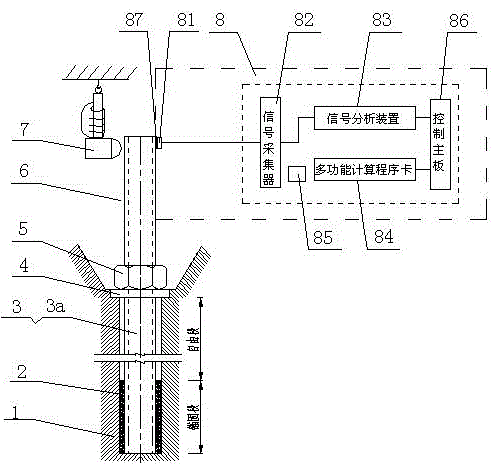
图1为本发明监测加固工程预紧力动态的预应力钢杆智能锚固系统的主视图。 Fig. 1 is the front view of the prestressed steel rod intelligent anchorage system for monitoring the dynamic prestressing force of the reinforcement project according to the present invention.
图2为本发明监测加固工程预紧力动态的预应力钢杆智能锚固系统中预应力钢杆预紧力计算原理图。 Fig. 2 is a schematic diagram of calculating the prestressed force of the prestressed steel pole in the intelligent anchoring system for the prestressed steel pole of the present invention which monitors the dynamics of the prestressed force of the reinforcement project.
图3为本发明监测加固工程预紧力动态的预应力钢杆智能锚固系统中预应力钢杆内端预埋段采用柔性材料制作的结构图。 Fig. 3 is a structural diagram of the embedded section at the inner end of the prestressed steel rod made of flexible materials in the intelligent anchoring system for prestressed steel rods in the intelligent anchoring system for monitoring the dynamic pretension force of the reinforcement project according to the present invention.
图4为本发明监测加固工程预紧力动态的预应力钢杆智能锚固系统预应力钢杆张拉力与螺母长内的横截面抗弯刚度关系曲线图。 Fig. 4 is a graph showing the relationship between the tensile force of the prestressed steel rod and the cross-sectional bending stiffness within the length of the nut in the prestressed steel rod intelligent anchorage system for monitoring the dynamic preload force of the reinforcement project according to the present invention.
图中:1、加固对象, 2、锚固体,3、钢杆,3a、预应力钢杆,4、托板,5、螺母,6、外露段,7、击振器, 8、智能测力仪,81、加速度传感器, 82、信号采集器,83、信号分析装置,84、多功能计算程序卡,85、充电电池,86、控制主板,87、磁力吸座,L-螺母5底面至预应力钢杆3a外露段6顶端面的长,L1-螺母5长,L2-螺母5顶面至预应力钢杆3a外露段6顶端面的长,L3-螺母5底面至加速度传感器81内边缘的长。
In the figure: 1. Reinforcement object, 2. Anchor body, 3. Steel rod, 3a, prestressed steel rod, 4. Support plate, 5. Nut, 6. Exposed section, 7. Vibrator, 8. Intelligent force measurement instrument, 81, acceleration sensor, 82, signal collector, 83, signal analysis device, 84, multi-function calculation program card, 85, rechargeable battery, 86, control main board, 87, magnetic suction seat, L-
具体实施方式 Detailed ways
结合附图,监测加固工程预紧力动态的预应力钢杆智能锚固系统,它包括于选定的加固对象1内根据监测要求在规定位置植入钢杆3及托板4和螺母5,使钢杆3预埋段与加固对象1结合并经张拉成预应力钢杆3a, 钢杆3预埋段包括锚固段和自由段,钢杆3的锚固段与加固对象1结合的方式是钻孔灌浆锚固或混凝土现浇锚固;于预应力钢杆3a外端设置外露段6, 预应力钢杆3a外露段6长即螺母5顶面至预应力钢杆3a顶端面的长L2,L2应大于预应力钢杆3a直径的4倍;钢杆3预埋段是选用刚性材料中的螺纹钢筋制作或选用柔性材料中的钢索制作,当钢杆3预埋段选用柔性材料中的钢索制作时,须将钢索与选用螺纹钢筋等刚性材料制作的预应力钢杆3a外露段6,采用焊接或者扣锁等方式连接固定成整体;在预应力钢杆3a外露段6顶端处设一加速度传感器81及击振器7,加速度传感器81与智能测力仪8连接,该智能测力仪8中内置信号采集器82,信号分析装置83,多功能计算程序卡84,充电电池85和控制主板86,多功能计算程序卡84内设有供智能测力仪8调用的各种螺母5与钢杆3组合的计算程序。多功能计算程序卡84中相应计算程序方程基于阶梯形固端悬臂梁模型建立,采用解析法求解。使用击振器7,使预应力钢杆3a外露段6产生微幅振动,操作控制主板86的主界面,输入预应力钢杆3a外露段6长L2,L2即螺母5顶面至预应力钢杆3a外露段6顶端面的长,并运行信号采集器82执行信号采集命令,信号采集器82拾取预应力钢杆3a外露段6的振动电信号,该振动电信号经信号分析装置83转换成预应力钢杆3a外露段6的固有频率谱且由控制主板86的主界面显示,在控制主板86的主界面中选中固有频率,并将选中的固有频率传输给多功能计算程序卡84中相应计算程序,从而获取预应力钢杆3a传给托板4的预紧力,实现对加固工程预紧力动态的监测。
Combined with the accompanying drawings, the prestressed steel rod intelligent anchoring system for monitoring the dynamic pre-tightening force of the reinforcement project includes implanting
本发明的安装、检测原理。 Installation and detection principle of the present invention.
实施例A。 Example A.
①施工人员按照预应力加固工程的设计图纸对锚固系统进行定位预埋,定出安装位置和倾角,当加固工程要求钢杆3曲线布置时,预应力钢杆3a外露段6是选用刚性材料中的螺纹钢筋制作;钢杆3预埋段是选用柔性材料中的钢索制作,钢索与预应力钢杆3a外露段6在钢杆3预埋段的自由段距托板5的150mm处通过焊接或者扣接等方式连接固定;施工工序为:加固对象1内钻孔或预留安装位置→安装钢杆3→钢杆3底部锚固→钢索与预应力钢杆3a外露段6的焊接或扣接→张拉锁定→防腐保护;预应力钢杆3a外露段6按要求预留4倍钢杆3直径以上的预应力钢杆3a外露段6长L2,即螺母5底面至加速度传感器81内边缘的长。
①Constructors pre-locate and embed the anchorage system according to the design drawings of the prestressed reinforcement project, and determine the installation position and inclination angle. When the reinforcement project requires the
②监测加固工程预紧力动态的预应力钢杆智能锚固系统,它包括钢杆3、托板4和螺母5与加固对象1共同的作用,在托板4和锚固体2之间的自由段受拉,使钢杆3成为预应力钢杆3a;预应力钢杆3a外露段6的符号定义为:L-螺母5底面至预应力钢杆3a外露段6顶端面的长,L1-螺母5长,L2-螺母5顶面至预应力钢杆3a外露段6顶端面的长,L3-螺母5底面至加速度传感器81内边缘的长。
② An intelligent anchoring system for prestressed steel rods that monitors the dynamic pre-tightening force of the reinforcement project. It includes the joint action of the
③监测加固工程预紧力动态的预应力钢杆智能锚固系统,配套的智能测力仪8由外部联接的加速度传感器81及内置的信号采集器82、信号分析装置83、多功能计算程序卡84、充电电池85和控制主板86组成,在预应力钢杆3a外露段6顶端处使用磁力吸座87将加速度传感器81吸附固定,并同时准备击振器7,加速度传感器81与信号采集器82连接,信号采集器82采集加速度传感器81产生的电信号,信号分析装置83与信号采集器82相连用于分析电信号并获得频谱,多功能计算程序卡84中设有预应力钢杆3a预紧力与预应力钢杆3a外露段6的固有频率、物理几何要素有关的方程,这些方程因螺母5和钢杆3的不同而存在差别,方程种类多,测试人员可以根据加固工程中使用的螺母5和钢杆3的类别在多功能计算程序卡84设置的方程库中选取,控制主板86可以启动信号分析装置83和信号采集器82并调用多功能计算程序卡84中的有关方程,操作控制主板86的主界面输入预应力钢杆3a外露段6长L2并运行信号采集器82执行信号采集命令,使用击振器7使预应力钢杆3a外露段6振动,信号采集器82拾取此预应力钢杆3a外露段6的振动电信号,该振动电信号经信号分析装置83转换成预应力钢杆3a外露段6的固有频率谱且由控制主板86的主界面显示,在控制主板86的主界面中选中固有频率,并将选中的固有频率传输给多功能计算程序卡84,从而获取预应力钢杆3a传给托板4的预紧力。
③ An intelligent anchoring system for prestressed steel rods that monitors the dynamic pretension force of the reinforcement project. The supporting intelligent
实施例B。 Example B.
①经施工操作完成了由钢杆3转变为预应力钢杆3a的过程,按要求预应力钢杆3a外露段6的长L应大于预应力钢杆3a直径的4倍,即螺母5底面至预应力钢杆3a外露段6顶端面的长;预应力钢杆3a在竖向预应力锚杆挡土墙中普遍使用直径为 
②预应力钢杆3a外露段6的顶端处通过磁力吸座87固联安装加速度传感器81,加速度传感器81的振动方向应垂直于预应力钢杆3a外露段6轴线,如附图1所示,加速度传感器81选购LC0152型产品,电荷灵敏度为100mv/g,频率测量范围0.7至10000Hz,谐振频率30kHz、分辨率0.0002g,重量17g、安装螺纹为M5,并有配套的磁力吸座87,加速度传感器81和磁力吸座87的总重量为32g,加速度传感器81直径为16mm。
② The top of the exposed
③本实施例可确定螺母5长L1为52mm;螺母5顶面至预应力钢杆3a外露段6顶端面的长L2为152mm;螺母5底面至预应力钢杆3a外露段6顶端面的长L=L1+L2为204mm;螺母5底面至加速度传感器81内边缘的长L3=L1+L2-传感器直径为L3186mm;螺母5长L1和加速度传感器81直径在同一个加固工程中是固定值,对于不同的样本,只要测定螺母5顶面至预应力钢杆3a外露段6顶端面的长L2则整个阶梯形固端悬臂梁模型的几何要素就得到确定,几何要素是求解方程的关键。
3. the present embodiment can determine that the length L1 of the
④加速度传感器81通过屏蔽电缆与智能测力仪8中的信号采集器82相连。
④ The
⑤数据采集器82、信号分析装置83、多功能计算程序卡84与控制主板86之间通过集成电路连接,点击智能测力仪8界面通过控制主板86运行信号采集器82和信号分析装置83及调用多功能计算程序卡84。
5. The
⑥连接加速度传感器81和数据采集器82,操作智能测力仪8界面通过控制主板86运行信号采集器82开始信号采集,同时使用击振器7,该击振器7应能使预应力钢杆3a外露段6产生振动,由人工采用脉冲方式轻微击振预应力钢杆3a外露段6的顶端处,击振的方向应垂直于预应力钢杆3a外露段6轴线,3秒钟后操作智能测力仪8界面通过控制主板86使信号采集器82停止采集并运行信号分析装置83,对智能测力仪8界面显示的固有频谱图进行分析,选取预应力钢杆3a外露段6的一阶振动频率。
6. Connect the
⑦调用多功能计算程序卡84中的方程式进行预应力钢杆3a预紧力计算。
⑦ Call the equation in the multi-function
参见附图2。 See attached drawing 2.
1)计算原理。 1) Calculation principle.
视预应力钢杆3a外露段6即包括螺母5的整个钢杆3外端,即螺母5顶面至预应力钢杆3a外露段6顶端面的长L2为一阶梯形固端悬臂梁模型,不同的预紧力作用下,外套螺母5部分的预应力钢杆3a与螺母5及螺母5与托板4之间的接触程度不同,可以推断,不同的预紧力,预应力钢杆3a外端外套螺母5的部分有不同的抗弯刚度,则悬臂梁相应有不同的固有振动频率,利用固有频率与刚度的关系,通过测试固有频率,识别刚度,从刚度的变化获得张拉力。使用精确解析法来构建刚度与频率的关系,较能量法更稳定准确。
Considering that the exposed
按三段均匀梁列无阻尼动力方程如下: According to the three-segment uniform beam, the undamped dynamic equation is as follows:
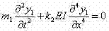

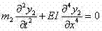
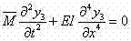
代入12个边界条件,联立12个方程,得其矩阵表达式: Substituting 12 boundary conditions and combining 12 equations, the matrix expression is obtained:

利用摄动法令包含频率和刚度的系数矩阵行列式为零 Use the perturbation rule to make the determinant of the coefficient matrix containing frequency and stiffness zero

式中:


将(5)式求得的




为预应力钢杆3a对托板4的预紧力。
is the pre-tightening force of the
上述实施例中预应力钢杆3a外露段长L2为152mm,所测出的一阶振动频率为540.8Hz,则张拉力为32.5吨。
In the above embodiment, the length L 2 of the exposed section of the
根据本发明基于视包括螺母5和预应力钢杆3a外露段6的整个外端为一阶梯形固端悬臂梁模型的计算原理,上述实施例中钢杆3预埋段是选用刚性材料或柔性材料制作都不影响计算结果,即只要外露段6为刚性材料中的螺纹钢筋制作,则钢杆3预埋段采用螺纹钢筋或钢索制作,都适应于本发明的计算原理。
According to the calculation principle of the present invention based on the entire outer end including the
以上仅仅是本发明的较佳实施例,根据本发明的上述构思,本领域的熟练人员还可对此做出各种修改和变换,然而,基于相同原理的变换和修改均属于本发明的实质。 The above are only preferred embodiments of the present invention, according to the above-mentioned design of the present invention, those skilled in the art can also make various modifications and transformations to this, however, transformations and modifications based on the same principle all belong to the essence of the present invention .
Claims (2)
Priority Applications (1)
| Application Number | Priority Date | Filing Date | Title |
|---|---|---|---|
| CN201010205238XA CN101864845B (en) | 2010-06-22 | 2010-06-22 | Prestress steel rod intelligent anchoring system monitoring dynamic state of strengthening engineering preload |
Applications Claiming Priority (1)
| Application Number | Priority Date | Filing Date | Title |
|---|---|---|---|
| CN201010205238XA CN101864845B (en) | 2010-06-22 | 2010-06-22 | Prestress steel rod intelligent anchoring system monitoring dynamic state of strengthening engineering preload |
Publications (2)
| Publication Number | Publication Date |
|---|---|
| CN101864845A CN101864845A (en) | 2010-10-20 |
| CN101864845B true CN101864845B (en) | 2012-06-06 |
Family
ID=42956753
Family Applications (1)
| Application Number | Title | Priority Date | Filing Date |
|---|---|---|---|
| CN201010205238XA Expired - Fee Related CN101864845B (en) | 2010-06-22 | 2010-06-22 | Prestress steel rod intelligent anchoring system monitoring dynamic state of strengthening engineering preload |
Country Status (1)
| Country | Link |
|---|---|
| CN (1) | CN101864845B (en) |
Families Citing this family (14)
| Publication number | Priority date | Publication date | Assignee | Title |
|---|---|---|---|---|
| CN102839664A (en) * | 2012-08-20 | 2012-12-26 | 长江勘测规划设计研究有限责任公司 | Rock-anchored crane beam with overall-process-stress-adjustable main load-bearing anchor rod and construction method |
| CN106092749A (en) * | 2016-06-03 | 2016-11-09 | 东北大学 | A kind of anchor rod drawing and measure on stress pulse assay device and method |
| CN108333061B (en) * | 2018-01-04 | 2024-01-23 | 中国建筑股份有限公司 | A system and method for measuring stress relaxation |
| CN109060219B (en) * | 2018-06-05 | 2020-01-24 | 广东华交科工程科技有限公司 | Cable force testing method based on unknown shock absorber support stiffness under complex boundary condition |
| CN108868188B (en) * | 2018-08-22 | 2023-12-12 | 天津核海源科技发展有限公司 | Tool for bonding and self-adsorption supporting locking of steel plate under limiting condition |
| CN110132478B (en) * | 2019-05-23 | 2020-09-22 | 湖南科技大学 | System and method for detecting foundation anchor bolt pre-tightening torque of wind driven generator |
| CN111157158B (en) * | 2020-01-06 | 2021-08-10 | 中国建筑第八工程局有限公司 | Detection and analysis method for residual stress of prestressed structure |
| CN111638119B (en) * | 2020-07-23 | 2021-06-25 | 兰州理工大学 | Slurry-soil interface strain testing method for earthen site anchoring system |
| CN113376018A (en) * | 2021-06-22 | 2021-09-10 | 广东和立土木工程有限公司 | Method and system for detecting tension force torque of prestressed finish-rolling threaded steel bar of concrete bridge |
| CN114720039B (en) * | 2022-06-02 | 2022-08-26 | 四川升拓检测技术股份有限公司 | Method for measuring effective prestress under anchor of finish rolling deformed steel bar |
| CN115478569A (en) * | 2022-09-14 | 2022-12-16 | 中冶成都勘察研究总院有限公司 | Prestressed non-destructive testing method based on natural frequency of precision-rolled rebar anti-floating anchor rod |
| CN115524047B (en) * | 2022-10-19 | 2026-03-20 | 长安大学 | Intelligent Detection System and Method for Effective Preload of Cable Clamp Bolts in In-Service Suspension Bridges Based on Pull-out Method |
| CN117900177B (en) * | 2023-11-06 | 2026-01-23 | 国能榆林能源有限责任公司 | System and method for automatically cleaning ejected anchor rod torque nut damping body |
| CN119089555B (en) * | 2024-09-04 | 2025-04-18 | 重庆交通大学 | A batch detection method for three-dimensional posture of embedded rod groups in arch abutments of large-span arch bridges |
Citations (7)
| Publication number | Priority date | Publication date | Assignee | Title |
|---|---|---|---|---|
| EP0429399A3 (en) * | 1989-11-20 | 1991-11-13 | Schlaepfer Messtechnik Ag | Stress measurement in metal-structures |
| DE202006006990U1 (en) * | 2006-04-27 | 2006-07-13 | Pfw Technologies Gmbh | Connecting component with temperature-resistant sensor element |
| EP1693659A1 (en) * | 2005-02-21 | 2006-08-23 | Werner Kluft | Force measuring device inside a fixing screw |
| CN101215822A (en) * | 2008-01-08 | 2008-07-09 | 中交第二公路勘察设计研究院有限公司 | Method and device for anchoring changeable prestressing force of suspension bridge |
| CN101419104A (en) * | 2008-11-28 | 2009-04-29 | 湖南科技大学 | Detecting based on concrete box beam bridge web vertical pre-stress rib stretching force |
| CN101435183A (en) * | 2008-12-05 | 2009-05-20 | 广州大学 | Method and apparatus for actively reinforcing wide-span concrete case beam bridge web |
| CN201335748Y (en) * | 2008-11-28 | 2009-10-28 | 湖南科技大学 | Detecting system based on concrete box girder bridge web-plate vertical pre-stressed reinforcing steel tensioning force |
-
2010
- 2010-06-22 CN CN201010205238XA patent/CN101864845B/en not_active Expired - Fee Related
Patent Citations (7)
| Publication number | Priority date | Publication date | Assignee | Title |
|---|---|---|---|---|
| EP0429399A3 (en) * | 1989-11-20 | 1991-11-13 | Schlaepfer Messtechnik Ag | Stress measurement in metal-structures |
| EP1693659A1 (en) * | 2005-02-21 | 2006-08-23 | Werner Kluft | Force measuring device inside a fixing screw |
| DE202006006990U1 (en) * | 2006-04-27 | 2006-07-13 | Pfw Technologies Gmbh | Connecting component with temperature-resistant sensor element |
| CN101215822A (en) * | 2008-01-08 | 2008-07-09 | 中交第二公路勘察设计研究院有限公司 | Method and device for anchoring changeable prestressing force of suspension bridge |
| CN101419104A (en) * | 2008-11-28 | 2009-04-29 | 湖南科技大学 | Detecting based on concrete box beam bridge web vertical pre-stress rib stretching force |
| CN201335748Y (en) * | 2008-11-28 | 2009-10-28 | 湖南科技大学 | Detecting system based on concrete box girder bridge web-plate vertical pre-stressed reinforcing steel tensioning force |
| CN101435183A (en) * | 2008-12-05 | 2009-05-20 | 广州大学 | Method and apparatus for actively reinforcing wide-span concrete case beam bridge web |
Also Published As
| Publication number | Publication date |
|---|---|
| CN101864845A (en) | 2010-10-20 |
Similar Documents
| Publication | Publication Date | Title |
|---|---|---|
| CN101864845B (en) | Prestress steel rod intelligent anchoring system monitoring dynamic state of strengthening engineering preload | |
| CN101419104B (en) | Testing system based on the tensile force of the vertical prestressed tendon in the web of concrete box girder bridge | |
| CN109406340B (en) | Device and method for testing grouting compactness of sleeve connecting structure by hammering pre-compression | |
| CN201145658Y (en) | Portable Field and Indoor Direct Shear Tester | |
| CN101082564A (en) | Stochastic nondestructive power detecting technology for detecting anchor rod pressure state | |
| CN101672751B (en) | Nondestructive test method for testing tension of prestress anchorage system | |
| CN110132478B (en) | System and method for detecting foundation anchor bolt pre-tightening torque of wind driven generator | |
| CN217424735U (en) | Prestress carbon fiber plate reinforcing system life-cycle health monitoring system | |
| CN101865739B (en) | Pre-tightening force dynamic monitoring system for pre-stressed anchor bar strengthening project | |
| CN107830898B (en) | Corrosion environment monitoring device based on optical fiber sensing and monitoring method thereof | |
| CN107084812B (en) | Detection system and method of vertical prestressing tendon tension force of concrete box girder bridge web | |
| WO2022099926A1 (en) | Fatigue test device for boot-shaped steel column foot for railway sound barrier, and fatigue test method therefor | |
| CN212007614U (en) | Vertical effective prestress detection device based on reverse pulling method | |
| CN111175068B (en) | Method for typical damage simulation device of cable-stayed bridge | |
| CN116593322B (en) | Method for monitoring and evaluating service performance of key tooth glue joint of segmental spliced box girder | |
| CN201335748Y (en) | Detecting system based on concrete box girder bridge web-plate vertical pre-stressed reinforcing steel tensioning force | |
| CN201883611U (en) | Prestress steel pole intelligent anchoring system used for monitoring the pretightening force dynamic of the strengthening engineering | |
| CN112097964B (en) | Device and method for detecting prestress of threaded steel bar based on magnetic flux test | |
| CN112683425A (en) | Method for detecting effective stress of longitudinal prestressed tendon in bridge body | |
| CN110512664B (en) | Hinge type anchor rope frame beam soil slope reinforcement power model device and test method | |
| CN210737631U (en) | Hinge type anchor cable frame beam reinforced soil slope power model device | |
| CN117782376A (en) | A method for detecting the engineering quality of assembled anchor rods or anchor cable frame beams and its application | |
| CN209460091U (en) | A kind of device hammering prepressing type test cartridge connection structure compactness of grouting | |
| Wang | Long-term health monitoring of post-tensioning box girder bridges | |
| Li et al. | Real-time Monitoring and Evaluation Algorithm of Civil Engineering Material Performance Based on Sensor |
Legal Events
| Date | Code | Title | Description |
|---|---|---|---|
| C06 | Publication | ||
| PB01 | Publication | ||
| C10 | Entry into substantive examination | ||
| SE01 | Entry into force of request for substantive examination | ||
| C14 | Grant of patent or utility model | ||
| GR01 | Patent grant | ||
| CF01 | Termination of patent right due to non-payment of annual fee |
Granted publication date: 20120606 |
|
| CF01 | Termination of patent right due to non-payment of annual fee |