CN201335748Y - Detecting system based on concrete box girder bridge web-plate vertical pre-stressed reinforcing steel tensioning force - Google Patents
Detecting system based on concrete box girder bridge web-plate vertical pre-stressed reinforcing steel tensioning force Download PDFInfo
- Publication number
- CN201335748Y CN201335748Y CNU2008201594628U CN200820159462U CN201335748Y CN 201335748 Y CN201335748 Y CN 201335748Y CN U2008201594628 U CNU2008201594628 U CN U2008201594628U CN 200820159462 U CN200820159462 U CN 200820159462U CN 201335748 Y CN201335748 Y CN 201335748Y
- Authority
- CN
- China
- Prior art keywords
- vertical
- concrete box
- prestressed tendon
- vertical prestressed
- box girder
- Prior art date
- Legal status (The legal status is an assumption and is not a legal conclusion. Google has not performed a legal analysis and makes no representation as to the accuracy of the status listed.)
- Expired - Fee Related
Links
Images
Landscapes
- Measurement Of Mechanical Vibrations Or Ultrasonic Waves (AREA)
Abstract
基于混凝土箱梁桥腹板竖向预应力筋张拉力的检测系统,它包括螺纹钢筋、波纹套管及螺母,其下部竖向预埋于混凝土箱梁桥腹板内经张拉成竖向预应力筋,于竖向预应力筋上部设外露段,外露段设加速度传感器及击振器,并与数据采集器、笔记本电脑及电源电连接,用于联接数据采集器的信号分析装置安装运行于笔记本电脑中,击振器得指令使竖向预应力筋外露段振动并经信号分析装置转换成竖向预应力筋外露段的固有频率,并应用计算关系式获取竖向预应力筋两螺母间的张拉力,克服了现有混凝土箱梁桥竖向预应力筋张拉力的检测均不能满足现场对竖向预应力筋张拉力质量进行大面积检测的缺陷;它适合大跨度预应力混凝土箱梁桥腹板竖向预应力筋张拉的检测。

A detection system based on the tensile force of the vertical prestressed tendons of the web of a concrete box girder bridge, which includes threaded steel bars, corrugated sleeves and nuts, the lower part of which is pre-embedded vertically in the web of a concrete box girder bridge and is stretched to form a vertical prestress The exposed section is set on the upper part of the vertical prestressed tendon, and the exposed section is provided with an acceleration sensor and a vibration device, and is electrically connected to the data collector, notebook computer and power supply. The signal analysis device used to connect the data collector is installed and operated on the notebook. In the computer, the vibrator is instructed to vibrate the exposed section of the vertical prestressed tendon, which is converted into the natural frequency of the exposed section of the vertical prestressed tendon by the signal analysis device, and the calculation relation is used to obtain the vibration between the two nuts of the vertical prestressed tendon Tensile force, overcomes the defect that the detection of the tension force of the vertical prestressed tendon of the existing concrete box girder bridge cannot meet the defect of large-scale detection of the quality of the tension force of the vertical prestressed tendon on site; it is suitable for long-span prestressed concrete box girder bridge Detection of web vertical prestressing tendon tension.
Description
技术领域 technical field
本实用新型涉及预应力混凝土构件的预应力钢筋张拉力的检测。尤其是一种基于混凝土箱梁桥腹板竖向预应力筋张拉力的检测系统。The utility model relates to the detection of the tensile force of prestressed steel bars of prestressed concrete components. In particular, it is a detection system based on the tensile force of the vertical prestressed tendon of the web plate of the concrete box girder bridge.
背景技术 Background technique
预应力混凝土连续(刚构)箱梁桥结构体系具有结构刚度大、行车平顺、伸缩缝少、养护费用低、适用于多种跨度等优点,自20世纪70年代以来,已成为高速公路、城市大中跨径混凝土桥梁设计方案的首选。为了减少和控制箱腹板主拉应力,防止腹板混凝土开裂,在箱梁腹板设置竖向预应力筋已经成为设计的重要内容之一。用精扎螺纹钢筋作为混凝土箱梁腹板竖向预应力筋,它具有连接不受焊接约束,锚固方便,施工简单,强度高,松驰性能佳等优点,至目前为止我国已建和在建的单跨跨径超过100m的预应力混凝土连续(刚构)箱梁桥梁中应用精扎螺纹钢筋竖向预应力体系已达数百座之多。它的不足之处是许多混凝土箱梁桥在施工和运营过程中腹板还是存在不同程度的开裂,尤其在大跨度预应力混凝土箱梁桥的腹板比较明显。有关文献披露:施加腹板竖向预应力并没能完全防止混凝土箱梁桥腹板的开裂,其主要原因之一是竖向预应力损失过大或失效。本申请人在进行大跨度预应力混凝土箱梁桥施工监控时,对竖向预应力筋的各项损失进行了全面和长期测试(在底端锚下安装测力传感器),结果表明:造成竖向预应力筋张拉力失效的主要原因是第一次初张拉不到位引起的。由于竖向预应力筋短,张拉过程中延伸量相对纵向预应力筋要小得多,且数量众多(100米跨,一般在2000根以上),在张拉后仅靠人工拧紧锚固螺母难以获得设计张拉力,如果拧紧锚固螺母的紧固力度不够,就会出现几乎失效现象,竖向预应力筋就成了摆设。即使通过计算能确定拧紧螺母的扭矩值,采用扭力板手拧紧螺母,或采用二次张拉,但人为因素的影响依然很大。解决竖向预应力问题最直接、最有效的途径就是提出一种有效的检测方法并制定相应的检测标准(桩基检测发展和完善就是实例)。目前,竖向预应力测量方法有在锚下安装压力传感器、在预应力表面粘贴电阻片测量法、张拉千斤顶油表测试法、预应力筋延伸量测量法,其中张拉千斤顶油表测试法、预应力筋延伸量测量法虽然简单易行,仅适合于张拉时预应力控制且精度较低,压力传感器和电阻片测量法,成本过高,且不能重复使用,虽能得到很好的测试精度,但不能满足现场对竖向预应力质量进行大面积检测的要求,无法推广应用,仅仅限于科学研究。The prestressed concrete continuous (rigid frame) box girder bridge structure system has the advantages of high structural rigidity, smooth driving, less expansion joints, low maintenance costs, and is suitable for various spans. Since the 1970s, it has become The first choice for the design of large and medium-span concrete bridges. In order to reduce and control the main tensile stress of the box web and prevent the web concrete from cracking, it has become one of the important contents of the design to set the vertical prestressed tendons on the box girder web. Using precision-rolled threaded steel bars as the vertical prestressed tendons of the web of concrete box girders has the advantages of not being bound by welding, convenient anchoring, simple construction, high strength, and good relaxation performance. So far, my country has built and is building Hundreds of prestressed concrete continuous (rigid frame) box girder bridges with a single-span span of more than 100m have been applied to the vertical prestressed system of precision-rolled threaded steel bars. Its shortcoming is that the webs of many concrete box girder bridges still have different degrees of cracking during construction and operation, especially in the webs of long-span prestressed concrete box girder bridges. Relevant literature discloses that the application of vertical prestress on the web does not completely prevent the cracking of the web of the concrete box girder bridge, and one of the main reasons is that the loss or failure of the vertical prestress is too large. The applicant carried out a comprehensive and long-term test on the losses of the vertical prestressed tendons when monitoring the construction of a long-span prestressed concrete box girder bridge (load sensors were installed under the bottom anchor), and the results showed that: The main reason for the failure of the tension to the prestressed tendons is that the first initial tension is not in place. Due to the short vertical prestressed tendons, the elongation during the tensioning process is much smaller than that of the longitudinal prestressed tendons, and the number is large (100 meters span, generally more than 2000), it is difficult to manually tighten the anchor nuts after tensioning. Obtain the design tension, if the tightening strength of the anchor nut is not enough, it will almost fail, and the vertical prestressed tendon will become a decoration. Even if the torque value of tightening the nut can be determined through calculation, the nut is tightened with a torque wrench, or the secondary tension is used, but the influence of human factors is still very large. The most direct and effective way to solve the vertical prestressing problem is to propose an effective detection method and formulate corresponding detection standards (the development and improvement of pile foundation detection is an example). At present, the vertical prestress measurement methods include installing pressure sensors under the anchor, pasting resistance sheet measurement methods on the prestressed surface, tension jack oil gauge test methods, and prestressed tendon elongation measurement methods. Among them, the tension jack oil gauge test method 1. Although the measurement method of prestressed tendon elongation is simple and easy, it is only suitable for prestress control during tension and has low precision. The pressure sensor and resistor sheet measurement method are too expensive and cannot be reused. The accuracy of the test, but it cannot meet the requirements of large-area testing of the vertical prestressed quality on site, and cannot be popularized and applied, and is only limited to scientific research.
发明内容 Contents of the invention
针对上述情况,本实用新型的目的提供一种基于混凝土箱梁桥腹板竖向预应力筋张拉力的检测系统,该系统结构简单,它不仅能适应大面积检测要求,而且能适应由螺母、外露螺栓组成的各种紧固构件的检测,检测成本较低,系统适应面广,使用安全可靠,便于普及推广。In view of the above situation, the purpose of this utility model is to provide a detection system based on the tension of the vertical prestressed tendons of the web of the concrete box girder bridge. The detection of various fastening components composed of exposed bolts has low detection cost, wide system adaptability, safe and reliable use, and is easy to popularize and promote.
为解决上述任务,基于混凝土箱梁桥腹板竖向预应力筋张拉力的检测系统,它包括螺纹钢筋、套于螺纹钢筋外的波纹套管及固定波纹套管的锚垫板、螺母,使其下部竖向预埋于混凝土箱梁桥腹板内经张拉成混凝土箱梁桥腹板的竖向预应力筋,于竖向预应力筋上部设置外露段,该外露段设一加速度传感器及击振器,加速度传感器与数据采集器、笔记本电脑及电源电连接,用于联接数据采集器的信号分析装置安装运行于笔记本电脑中,操作笔记本电脑,在信号分析装置界面中点击信号采集命令,击振器得指令动作,击振器使竖向预应力筋外露段振动,此竖向预应力筋外露段的振动信号经信号分析装置转换成竖向预应力筋外露段的固有频率且由信号分析装置界面显示,并应用信号分析装置中竖向预应力筋张拉力与竖向预应力筋外露段固有频率的计算关系式,从而获取竖向预应力筋两螺母之间的张拉力。In order to solve the above tasks, the tension detection system based on the vertical prestressed tendons of the concrete box girder bridge web includes threaded steel bars, corrugated sleeves sleeved outside the threaded steel bars, and anchor pads and nuts for fixing the corrugated sleeves. The lower part is pre-buried vertically in the web of the concrete box girder bridge and stretched to form a vertical prestressed tendon of the web of the concrete box girder bridge. An exposed section is set on the upper part of the vertical prestressed tendon. An acceleration sensor and shock absorber are arranged on the exposed section The vibrator, the acceleration sensor are electrically connected with the data collector, notebook computer and power supply, and the signal analysis device used to connect the data collector is installed and operated in the notebook computer. To operate the notebook computer, click the signal acquisition command in the interface of the signal analysis device, click The vibrator is commanded to act, and the vibrator vibrates the exposed section of the vertical prestressed tendon. The vibration signal of the exposed section of the vertical prestressed tendon is converted into the natural frequency of the exposed section of the vertical prestressed tendon by the signal analysis device and analyzed by the signal. The interface of the device is displayed, and the calculation relationship between the tension force of the vertical prestressed tendon and the natural frequency of the exposed section of the vertical prestressed tendon is applied in the signal analysis device, so as to obtain the tension force between the two nuts of the vertical prestressed tendon.
为了实现结构优化,其进一步措施是:In order to achieve structural optimization, its further measures are:
加速度传感器是经磁力吸座或橡胶泥或石膏泥固联于竖向预应力筋上部外露段顶端处。The acceleration sensor is fixedly connected to the top of the exposed section on the upper part of the vertical prestressed tendon through a magnetic suction seat or rubber mud or gypsum mud.
加速度传感器的振动方向是垂直于竖向预应力筋上部外露段轴线。The vibration direction of the acceleration sensor is perpendicular to the axis of the upper exposed section of the vertical prestressed tendon.
竖向预应力筋上部外露段的长度应大于竖向预应力筋直径的2.5倍。The length of the upper exposed section of the vertical prestressed tendon should be greater than 2.5 times the diameter of the vertical prestressed tendon.
竖向预应力筋上部外露段的长度应大于张拉施工预留长度80mm。The length of the upper exposed section of the vertical prestressed tendon should be 80mm greater than the reserved length for tension construction.
击振器应能使竖向预应力筋上部外露段产生振动,并能用于测试各类振动信息检测系统。The vibrator should be able to vibrate the upper exposed section of the vertical prestressed tendons, and can be used to test various vibration information detection systems.
本实用新型采用包括螺纹钢筋、套于螺纹钢筋外的波纹套管及固定波纹套管的锚垫板、螺母,使其下部竖向预埋于混凝土箱梁桥腹板内经张拉成混凝土箱梁桥腹板的竖向预应力筋,于竖向预应力筋上部设置外露段,该外露段设一加速度传感器及击振器,加速度传感器与数据采集器、笔记本电脑及电源电连接,用于联接数据采集器的信号分析装置安装运行于笔记本电脑中,操作笔记本电脑,击振器使竖向预应力筋外露段振动,振动信号经信号分析装置转换成竖向预应力筋外露段的固有频率,并应用信号分析装置中竖向预应力筋张拉力与竖向预应力筋外露段固有频率的计算关系式,从而获取竖向预应力筋两螺母之间的张拉力的技术解决方案,克服了现有混凝土箱梁桥竖向预应力筋张拉力的检测均不能满足现场对竖向预应力筋张拉力质量进行大面积检测的缺陷。The utility model adopts the threaded steel bar, the corrugated casing sleeve outside the threaded steel bar and the anchor backing plate and the nut fixing the corrugated casing, so that the lower part is vertically pre-buried in the web plate of the concrete box girder bridge and is stretched into a concrete box girder. The vertical prestressed tendon of the bridge web is provided with an exposed section on the upper part of the vertical prestressed tendon. The exposed section is provided with an acceleration sensor and a vibrator. The acceleration sensor is electrically connected with the data collector, a notebook computer and a power supply for connecting The signal analysis device of the data collector is installed and operated in the notebook computer. When the notebook computer is operated, the vibrator vibrates the exposed section of the vertical prestressed tendon, and the vibration signal is converted into the natural frequency of the exposed section of the vertical prestressed tendon by the signal analysis device. And apply the calculation relationship between the tension force of the vertical prestressed tendon and the natural frequency of the exposed section of the vertical prestressed tendon in the signal analysis device, so as to obtain the technical solution of the tension force between the two nuts of the vertical prestressed tendon, which overcomes the existing The detection of the tension of vertical prestressed tendons of concrete box girder bridges cannot meet the defect of large-scale inspection of the quality of vertical prestressed tendons on site.
本实用新型相比现有技术所产生的有益效果:Compared with the beneficial effects produced by the prior art, the utility model:
(I)检测系统结构简单,它不仅能适应大面积检测要求,而且能实现对现有由螺母、外露螺栓组成的各种紧固构件的检测;(1) The detection system is simple in structure, it can not only adapt to the large-area detection requirements, but also can realize the detection of existing various fastening components composed of nuts and exposed bolts;
(II)击振器能应用于各类型号的使竖向预应力筋上部外露段产生振动的测试振动信息的系统。(II) The vibrator can be applied to various types of systems for testing vibration information by vibrating the upper exposed section of the vertical prestressed tendons.
(III)加速度传感器是经磁力吸座或橡胶泥或石膏泥固联于竖向预应力筋上部外露段顶端处的,它与竖向预应力筋的联结或分离均十分方便,提高了测试系统的快速监测能力;(III) The acceleration sensor is fixedly connected to the top of the exposed section of the upper part of the vertical prestressed tendon through a magnetic suction seat or rubber mud or gypsum mud. It is very convenient to connect or separate from the vertical prestressed tendon, which improves the test system. rapid monitoring capabilities;
(IV)它具有快速、重复安装与安全使用功能;(IV) It has fast, repeated installation and safe use functions;
(V)它彻底地解决了竖向预应力损失过大和失效的问题,对防止预应力混凝土箱梁桥腹板开裂、提高此类桥梁的耐久性和可靠性具有重要的技术、经济效果,商业前景十分可观。(V) It completely solves the problem of excessive vertical prestress loss and failure, and has important technical and economic effects on preventing prestressed concrete box girder bridge webs from cracking and improving the durability and reliability of such bridges. Commercial The prospects are very promising.
它适合大跨度预应力混凝土箱梁桥腹板竖向预应力筋张拉的检测。It is suitable for the detection of vertical prestressed tendon tension of the web plate of long-span prestressed concrete box girder bridge.
下面结合附图和具体实施方式对本实用新型的测试系统和操作流程作进一步详细的说明。The test system and operation process of the present utility model will be further described in detail below in conjunction with the accompanying drawings and specific embodiments.
附图说明 Description of drawings
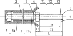
图1为本实用新型基于混凝土箱梁桥腹板竖向预应力筋张拉力的检测系统的主视图。Fig. 1 is the front view of the utility model based on the detection system of the tension force of the vertical prestressed tendon of the concrete box girder bridge web.
图2为本实用新型基于混凝土箱梁桥腹板竖向预应力筋张拉力的检测系统竖向预应力筋张拉力计算原理图。Fig. 2 is a schematic diagram of the calculation principle of the vertical prestressed tendon tension of the detection system based on the vertical prestressed tendon tension of the web plate of the concrete box girder bridge according to the present invention.
图中:1、螺纹钢筋,1a、竖向预应力筋,101、信号分析装置,102、计算关系式,103、磁力吸座,2、波纹套管,3、锚垫板,4、螺母,5、混凝土箱梁桥腹板,51、箱梁桥腹板混凝土,6、外露段,7、加速度传感器,71、磁力吸座,72、橡胶泥,73、石膏泥,8、击振器,9、数据采集器,10、笔记本电脑,L、竖向预应力筋上部外露段总长度,L1、套于竖向预应力筋的螺母厚度,L2、竖向预应力筋外露段长度,L3、螺母顶面至加速度传感器内边缘距离。In the figure: 1, threaded steel bar, 1a, vertical prestressed tendon, 101, signal analysis device, 102, calculation relational formula, 103, magnetic suction seat, 2, corrugated casing, 3, anchor plate, 4, nut, 5. Concrete box girder bridge web, 51. Box girder bridge web concrete, 6. Exposed section, 7. Acceleration sensor, 71. Magnetic suction seat, 72. Rubber clay, 73. Gypsum mud, 8. Vibrator, 9. Data collector, 10. Notebook computer, L. Total length of the upper exposed section of the vertical prestressed tendon, L 1. Thickness of the nut set on the vertical prestressed tendon, L 2. Length of the exposed section of the vertical prestressed tendon, L 3 , the distance from the top surface of the nut to the inner edge of the acceleration sensor.
具体实施方式 Detailed ways
参见附图,基于混凝土箱梁桥腹板竖向预应力筋张拉力的检测系统,它包括螺纹钢筋1、套于螺纹钢筋1外的波纹套管2及固定波纹套管2的锚垫板3、螺母4,使其1下部竖向预埋于混凝土箱梁桥腹板5内经张拉成混凝土箱梁桥腹板5的竖向预应力筋1a,于竖向预应力筋1a上部设置外露段6,为了达到较可靠的测量效果,竖向预应力筋1a上部外露段6的长度应大于竖向预应力筋1a直径的2.5倍;同时,竖向预应力筋1a上部外露段6的长度应大于张拉施工预留长度80mm。竖向预应力筋1a外露段6设一加速度传感器7及击振器8,加速度传感器7是经磁力吸座71或橡胶泥72或石膏泥73固联于竖向预应力筋1a上部外露段6顶端处,本实施方式中主要采用磁力吸座71;为了扩大使用范围,击振器8应能使竖向预应力筋1a上部外露段6产生振动,并能用于测试各类振动信息检测系统;加速度传感器7与数据采集器9、笔记本电脑10及电源103电连接,用于联接数据采集器9的信号分析装置101安装运行于笔记本电脑10中,操作笔记本电脑10,在信号分析装置101界面中点击信号采集命令,击振器8得指令动作,击振器8使竖向预应力筋1a外露段6及加速度传感器7振动,加速度传感器7的振动方向是垂直于竖向预应力筋1a上部外露段6轴线;此竖向预应力筋1a外露段6的振动信号经信号分析装置101转换成竖向预应力筋1a外露段6的固有频率且由信号分析装置101界面显示,并应用信号分析装置101中竖向预应力筋1a张拉力与竖向预应力筋1a外露段6固有频率的计算关系式102,从而获取竖向预应力筋1a两螺母3之间的张拉力。Referring to the accompanying drawings, the detection system based on the tensile force of the vertical prestressed tendon of the web of a concrete box girder bridge includes a threaded steel bar 1, a
本实用新型的安装、检测原理:The installation and detection principle of the utility model:
实施例AExample A
①施工单位按照混凝土箱梁桥设计图纸安装普通钢筋,其中螺纹钢筋1外套波纹套管2,并在螺纹钢筋1的腹板的上下两端位置安装锚垫板3、螺母4,施工时,先按图设置模板,浇灌箱梁桥腹板混凝土51,混凝土达到强度后形成混凝土箱梁桥腹板5,然后,使螺纹钢筋1受张拉力,并拧紧上端的螺母4,通过两处的锚垫板3和螺母4与混凝土箱梁桥腹板5共同作用,使螺纹钢筋1受到张拉力,形成腹板竖向预应力筋1a,竖向预应力筋1a上部按要求设置外露段6,该外露段6的长度是张拉螺纹钢筋1时必须预留的,按照施工规范要求至少应大于张拉施工预留长度80mm,才能确保张拉过程的安全与可靠,本实用新型的竖向预应力筋1a上部按要求设置外露段时应考虑适应其他检测系统的使用。① The construction unit installs ordinary steel bars according to the design drawings of the concrete box girder bridge, in which the threaded steel bars 1 are covered with
②基于混凝土箱梁桥腹板竖向预应力筋张拉的检测系统,它包括螺纹钢筋1在锚垫板3和螺母4与混凝土箱梁桥腹板5共同的作用,在两个螺母3之间的受张拉力,使螺纹钢筋1成为竖向预应力筋1a。② The detection system based on the tension of the vertical prestressed tendon of the concrete box girder bridge web, which includes the joint action of the threaded steel bar 1 on the
实施例BExample B
①经施工操作完成了由螺纹钢筋1转变为竖向预应力筋1a的过程,按要求竖向预应力筋1a上部外露段6的长度应大于竖向预应力筋1a直径的2.5倍,竖向预应力筋1a上部外露段6的长度应大于张拉施工预留长度80mm,竖向预应力筋1a选用目前桥梁上普遍使用的直径为32mm螺纹钢筋1,螺纹型号为M34×3.0,配套螺母4高度55mm,外形为六角形,对边距为55mm,外露段6长度等于116mm。① After the construction operation, the process of transforming the threaded steel bar 1 into the vertical prestressed tendon 1a is completed. According to the requirements, the length of the upper exposed
②外露段6的顶端处通过磁力吸座71或橡胶泥72或石膏泥73固联安装加速度传感器7,加速度传感器7的振动方向应垂直于竖向预应力筋1a上部外露段6轴线,如附图所示,传感器7选购YD-65型产品,电荷灵敏度为414.15,频率测量范围5-1000Hz,并有配套的磁力吸座71,传感器7和磁力吸座71及联结丝杆的总重量为209g。②The top of the exposed
③加速度传感器选购适配的DH-5922数据采集器9,数据采集器9经配套的电荷适调器H5857-1与加速度传感器7用屏蔽电缆相联,电缆两端为插针式,它们通过加速度传感器7的插座与数据采集器9配套的电荷适调器H5857-1的插座相联结。③Acceleration sensor is selected and adapted to the DH-5922 data collector 9, and the data collector 9 is connected with the
④数据采集器9与笔记本电脑10用1394联结方式联接。4. The data collector 9 is connected with the notebook computer 10 in a 1394 connection mode.
⑤接通数据采集器9,使用信号分析装置101运行于笔记本电脑10中且与数据采集器9配套,按照数据采集器9配套的信号分析装置101操作说明输入加速度传感器7的灵敏度系数,点击信号采集界面开始信号采集,使用击振器8,该击振器8应能使竖向预应力筋1a上部外露段6产生振动,并能用于测试各类振动信息检测系统,由人工用手采用脉动方式轻微击振竖向预应力筋1a外露段6的顶端处,击振的方向应垂直于竖向预应力筋1a外露段6轴线,3秒钟后点击信号分析装置101的停止采集界面,按照系数说明书操作信号分析装置101,截取用人工脉动方式轻微击振竖向预应力筋1a外露段6的振动信号,进行频率分析,获取竖向预应力筋1a外露段6的一阶振动频率。⑤Connect the data collector 9, use the signal analysis device 101 to run in the notebook computer 10 and match it with the data collector 9, input the sensitivity coefficient of the
⑥竖向预应力筋1a张拉力计算⑥Calculation of tension force of vertical prestressed tendon 1a
参见附图see attached image
1)计算原理1) Calculation principle
视竖向预应力筋1a上部按要求设置外露段6加外套螺母4部分为一悬臂梁,不同的张拉力外套螺母4部分的竖向预应力筋1a与螺母4的紧密程度不同,同时螺母4与锚垫板3的压紧程度不同,可以推断,不同的张拉力,竖向预应力筋1a上部按要求设置外露段6加外套螺母4部分为一悬臂梁有不同的刚度,则相应有不同的固有频率,利用固有频率与刚度的关系,测定固有频率,推断刚度,从刚度的变化获得张拉力。Depending on the upper part of the vertical prestressed tendon 1a, the exposed
按下列两式计算张拉力:Calculate the tensile force according to the following two formulas:
式中:ω为竖向预应力筋1a外露段6的一阶振动频率In the formula: ω is the first-order vibration frequency of the exposed
其中I为竖向预应力筋1a上部按要求设置的外露段6的抗弯刚度,E为竖向预应力筋1a上部按要求设置的外露段6的弹性模量,m2为竖向预应力筋1a上部按要求设置的外露段6的单位长度的质量,M为加速度传感器7和磁力吸座71的质量。Wherein I is the flexural rigidity of the exposed
将(1)式求得的k2代入下式:Substitute the k2 obtained from formula (1) into the following formula:
T=-6.9507(k2)5+45.113(k2)4-95.719(k2)3+83.531(k2)2-22.688(k2)+1.4945(2)T=-6.9507(k 2 ) 5 +45.113(k 2 ) 4 -95.719(k 2 ) 3 +83.531(k 2 ) 2 -22.688(k 2 )+1.4945(2)
T为竖向预应力筋1a外露段6的张拉力。T is the tensile force of the exposed
上述实施例中竖向预应力筋外露段长度L2为116mm,所测出的一阶频率为753.1Hz,则张拉力为45.63吨。In the above embodiment, the length L 2 of the exposed section of the vertical prestressed tendon is 116 mm, and the measured first-order frequency is 753.1 Hz, so the tensile force is 45.63 tons.
以上仅仅是本实用新型的较佳实施例,根据本实用新型的上述构思,本领域的熟练人员还可对此做出各种修改和变换。例如,竖向预应力筋上部按要求设置外露段,以及外露段经磁力吸座或橡胶泥或石膏泥达到快速安装传感器,且传感器安装在竖向预应力筋不同的位置,将信号分析仪与笔记本电脑部分功能合二为一,并将原理关系式固化在合二为一仪器中,信号采集器与计算机联接等相互连接及结构的修改和变换,计算关系式在不改变原理情况下的修正。然而,类似的这种变换和修改均属于本实用新型的实质。The above are only preferred embodiments of the present utility model, and those skilled in the art can also make various modifications and transformations to this according to the above-mentioned concept of the present utility model. For example, the upper part of the vertical prestressed tendon is provided with an exposed section as required, and the exposed section can be quickly installed with a sensor through a magnetic suction seat or rubber mud or gypsum mud, and the sensor is installed at a different position of the vertical prestressed tendon. Some functions of the notebook computer are combined into one, and the principle relational formula is solidified in the two-in-one instrument, the signal collector and the computer are connected to each other and the structure is modified and transformed, and the calculation relational formula is corrected without changing the principle . However, similar changes and modifications all belong to the essence of the present utility model.
Claims (6)
Priority Applications (1)
| Application Number | Priority Date | Filing Date | Title |
|---|---|---|---|
| CNU2008201594628U CN201335748Y (en) | 2008-11-28 | 2008-11-28 | Detecting system based on concrete box girder bridge web-plate vertical pre-stressed reinforcing steel tensioning force |
Applications Claiming Priority (1)
| Application Number | Priority Date | Filing Date | Title |
|---|---|---|---|
| CNU2008201594628U CN201335748Y (en) | 2008-11-28 | 2008-11-28 | Detecting system based on concrete box girder bridge web-plate vertical pre-stressed reinforcing steel tensioning force |
Publications (1)
| Publication Number | Publication Date |
|---|---|
| CN201335748Y true CN201335748Y (en) | 2009-10-28 |
Family
ID=41287403
Family Applications (1)
| Application Number | Title | Priority Date | Filing Date |
|---|---|---|---|
| CNU2008201594628U Expired - Fee Related CN201335748Y (en) | 2008-11-28 | 2008-11-28 | Detecting system based on concrete box girder bridge web-plate vertical pre-stressed reinforcing steel tensioning force |
Country Status (1)
| Country | Link |
|---|---|
| CN (1) | CN201335748Y (en) |
Cited By (5)
| Publication number | Priority date | Publication date | Assignee | Title |
|---|---|---|---|---|
| CN101864845A (en) * | 2010-06-22 | 2010-10-20 | 湖南科技大学 | Intelligent anchoring system for prestressed steel rods monitoring the dynamics of prestressed force in reinforcement projects |
| CN101865739A (en) * | 2010-06-22 | 2010-10-20 | 湖南科技大学 | Dynamic Monitoring System of Pre-tightening Force in Pre-stressed Anchor Reinforcement Engineering |
| CN107084812A (en) * | 2017-06-14 | 2017-08-22 | 湖南科技大学 | Testing system and method for vertical prestressed tendon tension of concrete box girder bridge web |
| CN108332891A (en) * | 2018-04-17 | 2018-07-27 | 青岛理工大学 | Reinforced concrete corrosion test mold and corrosion process stress monitoring method |
| CN115478569A (en) * | 2022-09-14 | 2022-12-16 | 中冶成都勘察研究总院有限公司 | Prestressed non-destructive testing method based on natural frequency of precision-rolled rebar anti-floating anchor rod |
-
2008
- 2008-11-28 CN CNU2008201594628U patent/CN201335748Y/en not_active Expired - Fee Related
Cited By (8)
| Publication number | Priority date | Publication date | Assignee | Title |
|---|---|---|---|---|
| CN101864845A (en) * | 2010-06-22 | 2010-10-20 | 湖南科技大学 | Intelligent anchoring system for prestressed steel rods monitoring the dynamics of prestressed force in reinforcement projects |
| CN101865739A (en) * | 2010-06-22 | 2010-10-20 | 湖南科技大学 | Dynamic Monitoring System of Pre-tightening Force in Pre-stressed Anchor Reinforcement Engineering |
| CN101864845B (en) * | 2010-06-22 | 2012-06-06 | 湖南科技大学 | Prestress steel rod intelligent anchoring system monitoring dynamic state of strengthening engineering preload |
| CN101865739B (en) * | 2010-06-22 | 2012-07-25 | 湖南科技大学 | Pre-tightening force dynamic monitoring system for pre-stressed anchor bar strengthening project |
| CN107084812A (en) * | 2017-06-14 | 2017-08-22 | 湖南科技大学 | Testing system and method for vertical prestressed tendon tension of concrete box girder bridge web |
| CN108332891A (en) * | 2018-04-17 | 2018-07-27 | 青岛理工大学 | Reinforced concrete corrosion test mold and corrosion process stress monitoring method |
| CN108332891B (en) * | 2018-04-17 | 2024-01-26 | 青岛理工大学 | A test mold for reinforced concrete corrosion and a stress monitoring method for the corrosion process |
| CN115478569A (en) * | 2022-09-14 | 2022-12-16 | 中冶成都勘察研究总院有限公司 | Prestressed non-destructive testing method based on natural frequency of precision-rolled rebar anti-floating anchor rod |
Similar Documents
| Publication | Publication Date | Title |
|---|---|---|
| CN101419104A (en) | Detecting based on concrete box beam bridge web vertical pre-stress rib stretching force | |
| CN101864845B (en) | Prestress steel rod intelligent anchoring system monitoring dynamic state of strengthening engineering preload | |
| US10247718B2 (en) | Non-destructive apparatus, system and method for determining pull-out capacity of anchor bolts | |
| CN107084812B (en) | Detection system and method of vertical prestressing tendon tension force of concrete box girder bridge web | |
| CN201746774U (en) | Cable-stayed bridge cable tower anchorage zone steel bracket with assembled anchoring device | |
| CN111455859A (en) | Construction method for bracket of No. 0 and No. 1 steel bridge with high piers and continuous steel structure | |
| CN110132478B (en) | System and method for detecting foundation anchor bolt pre-tightening torque of wind driven generator | |
| CN201335748Y (en) | Detecting system based on concrete box girder bridge web-plate vertical pre-stressed reinforcing steel tensioning force | |
| CN107238568A (en) | Method of testing and loading device based on corrosion and the armored concrete bond-slip properties of fatigue load coupling influence | |
| CN101806714B (en) | Beam tester of bonding strength of fibre reinforced composite sheet and concrete | |
| CN206832583U (en) | It is a kind of to be used for the experimental rig of anchor pole stretching and shearing in jointed rock mass | |
| CN108760495A (en) | The two-way tension adhesion test device of weak separation muscle material and test method | |
| CN103837279A (en) | Prestress anchoring structure tensioning force detecting system based on single-freedom-degree system | |
| CN102507439A (en) | Testing device and method for directly testing adhesive property between early-age concrete and reinforcing steel bars | |
| CN102914470A (en) | Device and method for testing concrete sample beam stiffness | |
| CN212007614U (en) | Vertical effective prestress detection device based on reverse pulling method | |
| CN103485287A (en) | Prestressed application method in concrete frame box culvert construction | |
| CN111175068B (en) | Method for typical damage simulation device of cable-stayed bridge | |
| CN104020056A (en) | Loading method of concrete creep test under action of bending, shearing and pressing compound stress | |
| CN104034609B (en) | A kind of test method of stress gradient on the impact of beams of concrete Creep Characteristics of studying | |
| CN110512664A (en) | Dynamic model device and test method for strengthening soil slope with hinged anchor cable frame beam | |
| CN216816275U (en) | A system for testing the mechanical performance of composite bridge decks under eccentric loads | |
| CN202330250U (en) | Testing device for directly measuring bonding performance of early-stage concrete and steel bars | |
| CN102750856B (en) | Experiment model for continuous beam | |
| Fehling et al. | Gärtnerplatz–Bridge over River Fulda in Kassel: Multispan Hybrid UHPC‐Steel Bridge |
Legal Events
| Date | Code | Title | Description |
|---|---|---|---|
| C14 | Grant of patent or utility model | ||
| GR01 | Patent grant | ||
| C17 | Cessation of patent right | ||
| CF01 | Termination of patent right due to non-payment of annual fee |
Granted publication date: 20091028 Termination date: 20111128 |