KR20160008169A - Compact robotic wrist - Google Patents
Compact robotic wrist Download PDFInfo
- Publication number
- KR20160008169A KR20160008169A KR1020157029314A KR20157029314A KR20160008169A KR 20160008169 A KR20160008169 A KR 20160008169A KR 1020157029314 A KR1020157029314 A KR 1020157029314A KR 20157029314 A KR20157029314 A KR 20157029314A KR 20160008169 A KR20160008169 A KR 20160008169A
- Authority
- KR
- South Korea
- Prior art keywords
- pulleys
- cable
- tool
- sets
- cables
- Prior art date
- Legal status (The legal status is an assumption and is not a legal conclusion. Google has not performed a legal analysis and makes no representation as to the accuracy of the status listed.)
- Abandoned
Links
Images








Classifications
-
- B—PERFORMING OPERATIONS; TRANSPORTING
- B25—HAND TOOLS; PORTABLE POWER-DRIVEN TOOLS; MANIPULATORS
- B25J—MANIPULATORS; CHAMBERS PROVIDED WITH MANIPULATION DEVICES
- B25J17/00—Joints
- B25J17/02—Wrist joints
-
- A61B19/2203—
-
- A—HUMAN NECESSITIES
- A61—MEDICAL OR VETERINARY SCIENCE; HYGIENE
- A61B—DIAGNOSIS; SURGERY; IDENTIFICATION
- A61B17/00—Surgical instruments, devices or methods
- A61B17/28—Surgical forceps
- A61B17/29—Forceps for use in minimally invasive surgery
-
- A—HUMAN NECESSITIES
- A61—MEDICAL OR VETERINARY SCIENCE; HYGIENE
- A61B—DIAGNOSIS; SURGERY; IDENTIFICATION
- A61B34/00—Computer-aided surgery; Manipulators or robots specially adapted for use in surgery
- A61B34/30—Surgical robots
-
- A—HUMAN NECESSITIES
- A61—MEDICAL OR VETERINARY SCIENCE; HYGIENE
- A61B—DIAGNOSIS; SURGERY; IDENTIFICATION
- A61B34/00—Computer-aided surgery; Manipulators or robots specially adapted for use in surgery
- A61B34/70—Manipulators specially adapted for use in surgery
- A61B34/71—Manipulators operated by drive cable mechanisms
-
- B—PERFORMING OPERATIONS; TRANSPORTING
- B25—HAND TOOLS; PORTABLE POWER-DRIVEN TOOLS; MANIPULATORS
- B25J—MANIPULATORS; CHAMBERS PROVIDED WITH MANIPULATION DEVICES
- B25J15/00—Gripping heads and other end effectors
- B25J15/0028—Gripping heads and other end effectors with movable, e.g. pivoting gripping jaw surfaces
-
- B—PERFORMING OPERATIONS; TRANSPORTING
- B25—HAND TOOLS; PORTABLE POWER-DRIVEN TOOLS; MANIPULATORS
- B25J—MANIPULATORS; CHAMBERS PROVIDED WITH MANIPULATION DEVICES
- B25J15/00—Gripping heads and other end effectors
- B25J15/02—Gripping heads and other end effectors servo-actuated
- B25J15/0253—Gripping heads and other end effectors servo-actuated comprising parallel grippers
- B25J15/0286—Gripping heads and other end effectors servo-actuated comprising parallel grippers actuated by chains, cables or ribbons
-
- A—HUMAN NECESSITIES
- A61—MEDICAL OR VETERINARY SCIENCE; HYGIENE
- A61B—DIAGNOSIS; SURGERY; IDENTIFICATION
- A61B17/00—Surgical instruments, devices or methods
- A61B17/28—Surgical forceps
- A61B17/29—Forceps for use in minimally invasive surgery
- A61B2017/2926—Details of heads or jaws
- A61B2017/2932—Transmission of forces to jaw members
- A61B2017/2938—Independently actuatable jaw members, e.g. two actuating rods
-
- A61B2019/2238—
-
- A61B2019/2242—
-
- A61B2019/2246—
-
- A—HUMAN NECESSITIES
- A61—MEDICAL OR VETERINARY SCIENCE; HYGIENE
- A61B—DIAGNOSIS; SURGERY; IDENTIFICATION
- A61B34/00—Computer-aided surgery; Manipulators or robots specially adapted for use in surgery
- A61B34/30—Surgical robots
- A61B2034/305—Details of wrist mechanisms at distal ends of robotic arms
-
- A—HUMAN NECESSITIES
- A61—MEDICAL OR VETERINARY SCIENCE; HYGIENE
- A61B—DIAGNOSIS; SURGERY; IDENTIFICATION
- A61B34/00—Computer-aided surgery; Manipulators or robots specially adapted for use in surgery
- A61B34/30—Surgical robots
- A61B2034/305—Details of wrist mechanisms at distal ends of robotic arms
- A61B2034/306—Wrists with multiple vertebrae
-
- A—HUMAN NECESSITIES
- A61—MEDICAL OR VETERINARY SCIENCE; HYGIENE
- A61B—DIAGNOSIS; SURGERY; IDENTIFICATION
- A61B34/00—Computer-aided surgery; Manipulators or robots specially adapted for use in surgery
- A61B34/70—Manipulators specially adapted for use in surgery
- A61B34/71—Manipulators operated by drive cable mechanisms
- A61B2034/715—Cable tensioning mechanisms for removing slack
-
- Y—GENERAL TAGGING OF NEW TECHNOLOGICAL DEVELOPMENTS; GENERAL TAGGING OF CROSS-SECTIONAL TECHNOLOGIES SPANNING OVER SEVERAL SECTIONS OF THE IPC; TECHNICAL SUBJECTS COVERED BY FORMER USPC CROSS-REFERENCE ART COLLECTIONS [XRACs] AND DIGESTS
- Y10—TECHNICAL SUBJECTS COVERED BY FORMER USPC
- Y10S—TECHNICAL SUBJECTS COVERED BY FORMER USPC CROSS-REFERENCE ART COLLECTIONS [XRACs] AND DIGESTS
- Y10S901/00—Robots
- Y10S901/27—Arm part
- Y10S901/28—Joint
- Y10S901/29—Wrist
-
- Y—GENERAL TAGGING OF NEW TECHNOLOGICAL DEVELOPMENTS; GENERAL TAGGING OF CROSS-SECTIONAL TECHNOLOGIES SPANNING OVER SEVERAL SECTIONS OF THE IPC; TECHNICAL SUBJECTS COVERED BY FORMER USPC CROSS-REFERENCE ART COLLECTIONS [XRACs] AND DIGESTS
- Y10—TECHNICAL SUBJECTS COVERED BY FORMER USPC
- Y10S—TECHNICAL SUBJECTS COVERED BY FORMER USPC CROSS-REFERENCE ART COLLECTIONS [XRACs] AND DIGESTS
- Y10S901/00—Robots
- Y10S901/30—End effector
- Y10S901/31—Gripping jaw
- Y10S901/36—Actuating means
-
- Y—GENERAL TAGGING OF NEW TECHNOLOGICAL DEVELOPMENTS; GENERAL TAGGING OF CROSS-SECTIONAL TECHNOLOGIES SPANNING OVER SEVERAL SECTIONS OF THE IPC; TECHNICAL SUBJECTS COVERED BY FORMER USPC CROSS-REFERENCE ART COLLECTIONS [XRACs] AND DIGESTS
- Y10—TECHNICAL SUBJECTS COVERED BY FORMER USPC
- Y10S—TECHNICAL SUBJECTS COVERED BY FORMER USPC CROSS-REFERENCE ART COLLECTIONS [XRACs] AND DIGESTS
- Y10S901/00—Robots
- Y10S901/30—End effector
- Y10S901/31—Gripping jaw
- Y10S901/36—Actuating means
- Y10S901/38—Electric motor
Landscapes
- Health & Medical Sciences (AREA)
- Engineering & Computer Science (AREA)
- Surgery (AREA)
- Life Sciences & Earth Sciences (AREA)
- Robotics (AREA)
- Heart & Thoracic Surgery (AREA)
- Nuclear Medicine, Radiotherapy & Molecular Imaging (AREA)
- Biomedical Technology (AREA)
- Medical Informatics (AREA)
- Molecular Biology (AREA)
- Animal Behavior & Ethology (AREA)
- General Health & Medical Sciences (AREA)
- Public Health (AREA)
- Veterinary Medicine (AREA)
- Mechanical Engineering (AREA)
- Ophthalmology & Optometry (AREA)
- Manipulator (AREA)
- Surgical Instruments (AREA)
Abstract
수술용 툴은 툴 샤프트, 엔드 이펙터, 및 엔드 이펙터를 툴 샤프트에 연결하는 리스트를 포함한다. 툴은, 드라이브 메커니즘과 리스트 사이에서 연장하는 2개 이상의 독립적인 케이블들의 4개의 독립적인 케이블 단부들의 독립적인 구동을 통해 리스트 및 엔드 이펙터 중 하나 또는 둘 모두의 요 및 피치 움직임에 영향을 주도록 구성된 드라이브 메커니즘을 포함한다.The surgical tool includes a tool shaft, an end effector, and a list connecting the end effector to the tool shaft. The tool is configured to drive a drive configured to effect yaw and pitch movement of one or both of the list and end effectors through independent drive of four independent cable ends of two or more independent cables extending between the drive mechanism and the list Mechanism.
Description
임의의 우선권 출원들에 대한 참조에 의한 통합Consolidation by reference to any priority applications
본 출원은 2013년 03월 14일자로 출원된 미국 가특허 출원 제61/781092호 및 2013년 03월 15일자로 출원된 미구 가특허 출원 제61/791248호에 대한 U.S.C. §119(e) 하에서의 우선권을 주장하며, 이들의 전부는 그 전체가 본원에 참조로써 통합되며, 본 명세서의 일 부분으로서 간주된다.This application is a continuation-in-part of U.S. Provisional Patent Application No. 61/781092, filed on March 14, 2013, and U.S.C. Patent Application No. 61/791248, filed Mar. 15, 2013, Priority under §119 (e), all of which are incorporated herein by reference in their entirety and are considered a part of this specification.
기술분야Technical field
로봇 엔드 이펙터(end effector)들이 로봇들이 물체들을 조작할 수 있게끔 한다. 본 출원은 로봇 툴(tool)들, 툴들의 엔드 이펙터들, 및 이를 동작시키는 방법에 관한 것이다.Robot end effectors allow robots to manipulate objects. The present application relates to robotics tools, end effectors of tools, and methods of operating them.
로봇들은 산업, 연구, 의료 및 비-의료 목적들을 포함하는 다양한 목적들을 위해 사용된다. 각각의 상이한 유형의 로봇은 그 자체의 고유 특징들의 세트 및 특징들에 더하여 특성들을 가질 수 있으며, 특성들은 대부분의 로봇들 사이에서 공통된다. 대부분의 로봇들의 하나의 공통 특성은 툴들의 사용이다. 로봇들에 의해 제어되는 툴들이 다양한 작업들을 수행하기 위해 사용된다. 로봇에 의해 제어되는 각각의 툴이 수행되어야 할 작업에 대해 특별하게 설계될 수 있다. 전형적으로, 로봇 툴은 가늘고 긴 형상이며, 엔드 이펙터(예를 들어, 그래스퍼(grasper))를 갖는다. Robots are used for a variety of purposes, including industrial, research, medical and non-medical purposes. Each different type of robot can have characteristics in addition to its own set of features and features, and the characteristics are common among most robots. One common characteristic of most robots is the use of tools. Tools controlled by robots are used to perform various tasks. Each tool controlled by the robot can be specially designed for the task to be performed. Typically, the robot tool is elongate in shape and has an end effector (e.g., a grasper).
수술 시스템들에 대하여, 전형적인 상용(on-market) 로봇 시스템들은 케이블들 또는 다른 메커니즘들에 의해 제어되는 직선 강성(rigid) 툴들 또는 가요성 툴들(예를 들어, 만곡된 툴들)을 사용한다. 직선 강성 툴들이 일부 수술 세팅(setting)들에서, 예를 들어, 기관 또는 해부학적 구조가 절개 지점 또는 포트(예를 들어, 툴이 신체 내로 진입하는 위치)와 수술될 조직 사이에 위치할 때 부적당하며, 이는 직선 샤프트가 조직을 액세스하기 위해 기관 또는 해부학적 구조를 둘러 도달할 수 없기 때문이다. 직선 강성 툴들의 다른 결함은 이들이, 때때로 환자에 대한 상처를 제한하기 위해 바람직한, 2 이상의 툴이 단일 수술 절개부 또는 포트를 통해 도입되는 단일 포트 수술로서 지칭되는 것에 적합하지 않다는 것이다. 이러한 단일 포트 수술들에 있어, 봉합과 같은 작업들을 위해 복수의 툴들 사이에 협력적인 상호작용이 요구된다. 협력적으로 상호동작하기 위하여, 툴들이 상이한 각도들로부터 수술 공간 상에서 모여야 할 필요가 있지만, 직선 강성 툴들은 이러한 것에 대해 적합하지 않다.For surgical systems, typical on-market robotic systems use either straight rigid or flexible tools (e.g., curved tools) that are controlled by cables or other mechanisms. When straight stiffness tools are used in some surgical settings, for example when the organs or anatomical structures are located between the incision site or port (e.g., where the tool enters the body) Because the straight shaft can not reach the organs or anatomical structures to access the tissue. Another drawback of straight stiffness tools is that they are not suitable for being referred to as single port surgery where two or more tools are introduced through a single surgical incision or port, which is sometimes desirable to limit the wound on the patient. In these single-port surgeries, cooperative interaction between the plurality of tools is required for operations such as suturing. To interactively cooperate, straight stiffness tools are not suitable for this, although tools need to be gathered in the surgical space from different angles.
만곡된 또는 굽혀진 툴들과 같은 가요성 툴들과 관련하여, 이러한 툴들이 이상에서 논의된 직선 강성 툴들의 액세스 및 조작성 문제들 중 일부를 극복하지만, 결함들을 또한 갖는다. 가요성 툴들의 하나의 단점은 이들이 전형적으로 수술 절차들 동안 굽힘 하중(bending load)들에 저항하기에 충분한 강성이 아니라는 것이다. 일반적으로, 강성을 증가시키기 위하여, 툴들의 만곡된 또는 굽힘 프로파일이 제조사에 의해 또는 굽혀진 툴을 사용하는 사용자에 의해 신체 외부에서 사전-형성되며, 따라서 현장에서(in situ) 수술 기하구조를 적응시키기(accommodate) 위해 신체 내에서 굽혀질 수 없다. 단편화되거나 또는 가요성 샤프트들을 가지며, 예를 들어 케이블들에 의해 제어될 수 있는 다른 가요성 툴들이 이용가능하다. 이러한 가요성 툴들이 또한, 일단 수술 절차 동안 굽혀지면 굽힘 하중들에 저항하기에 충분한 강성을 달성할 수 없는 것과 같은 단점들을 갖는다.With regard to flexible tools such as curved or bent tools, these tools overcome some of the accessibility and manipulability problems of the linear stiffness tools discussed above, but also have deficiencies. One disadvantage of the flexible tools is that they are typically not rigid enough to withstand bending loads during surgical procedures. Generally, to increase stiffness, the curved or bend profile of the tools is pre-formed outside the body by the manufacturer or by a user using a bent tool, thus adapting the surgical geometry in situ Can not be bent in the body to accommodate. Other flexible tools are available that can be fragmented or have flexible shafts, for example, which can be controlled by cables. These flexible tools also have drawbacks such as not being able to achieve sufficient stiffness once they are bent during the surgical procedure to resist bending loads.
직선 강성 툴들 및 만곡되거나 또는 굽혀진 툴들이 또한 비-의료 애플리케이션들에서 사용되며, 상기 비-의료 애플리케이션들에서 사용될 때 이상에서 언급된 동일한 결함들을 갖는다.Linear rigid tools and curved or bent tools are also used in non-medical applications and have the same deficiencies mentioned above when used in non-medical applications.
따라서, 상용 툴들에 대하여 이상에서 언급된 결함들을 처리하는 개선된 로봇 툴들 및 엔드 이펙터들에 대한 필요성이 존재한다. 상용 로봇 툴들과 관련하여, 작업지점의 더 적은 폐색, 복잡한 수술들을 수행하기 위한 향상된 능력, 및 액세스가 제한된 영역들에서 작업하기 위한 향상된 성능을 제공하는 개선된 로봇 툴들에 대한 필요성이 존재한다.Thus, there is a need for improved robotic tools and end effectors that address the above mentioned deficiencies for commercial tools. With respect to commercial robotic tools, there is a need for improved robotic tools that provide less occlusion of work points, improved ability to perform complex surgeries, and improved performance for working in restricted access areas.
본 발명의 일 측면에 따르면, 엔드 이펙터에 연결된 리스트(wrist)를 갖는 툴이 제공된다. 리스트는 독립적인 케이블 단부들을 포함할 수 있다. 4개의 독립적인 케이블 단부들이, 각각의 독립적인 케이블 단부가 독립적으로 드라이브(drive)될 수 있도록 배열될 수 있다. 일 실시예에 있어, 4개의 독립적인 케이블 단부들이 4개의 독립적인 케이블들에 의해 규정(define)된다. 다른 실시예에 있어, 4개의 독립적인 케이블 단부들이 2개의 케이블들에 의해 규정되며, 여기에서 각 케이블의 각 단부가 독립적인 케이블 단부를 규정한다.According to an aspect of the invention, a tool is provided having a wrist connected to an end effector. The list may include independent cable ends. Four independent cable ends can be arranged such that each independent cable end can be driven independently. In one embodiment, four independent cable ends are defined by four independent cables. In another embodiment, four independent cable ends are defined by two cables, wherein each end of each cable defines an independent cable end.
일 실시예에 있어, 툴이 각 케이블 단부를 독립적으로 제어하기 위한 4개의 모터들을 포함하도록 배열될 수 있다.In one embodiment, the tool may be arranged to include four motors for independently controlling each cable end.
본 발명의 일 측면에 따르면, 엔드 이펙터에 연결된 리스트를 갖는 툴은 케이블들 대신에 하나 이상의 꼬임형 스트링(twisted string)들을 가질 수 있다. 단일 스트링이 꼬임형 스트링과 유사하게 거동하도록 배열될 수 있다. 툴이 엔드 이펙터를 드라이브하는 하나 이상의 꼬임형 스트링들을 가질 수 있다.According to an aspect of the invention, a tool having a list connected to an end effector may have one or more twisted strings instead of cables. A single string can be arranged to behave like a twisted string. The tool may have one or more twisted strings that drive the end effector.
리스트 및 엔드 이펙터를 갖는 툴이 풀리(pulley)들의 3개 이상의 세트들을 갖도록 배열될 수 있다. 각각의 케이블이 2개의 직교 방향들에서 풀리들의 3개 이상의 세트들을 둘러 감도록, 각각의 케이블이 배열될 수 있다. 각 케이블의 2개의 측(side)들 사이의 상대적인 장력이 요 운동(yaw motion)을 야기하도록, 각각의 케이블이 배열될 수 있다. 각 케이블의 2개의 측들 사이의 상대적인 장력이 피치 운동(pitch motion)을 야기하도록, 각각의 케이블이 배열될 수 있다.The list and the tool with the end effector can be arranged to have three or more sets of pulleys. Each cable can be arranged such that each cable surrounds three or more sets of pulleys in two orthogonal directions. Each cable can be arranged such that the relative tension between the two sides of each cable results in yaw motion. Each cable can be arranged such that the relative tension between the two sides of each cable causes pitch motion.
리스트 및 엔드 이펙터를 갖는 툴이 풀리들의 3개의 세트들 및 풀리들의 2개의 추가적인 세트들을 갖도록 배열될 수 있다. 각각의 케이블이 2개의 직교 방향들에서 풀리들의 3개의 세트들을 둘러 감도록, 각각의 케이블이 배열될 수 있다. 풀리들의 2개의 추가적인 세트들이 풀리들의 3개의 세트들에 대하여 각도를 가질 수 있다. 풀리들의 2개의 추가적인 세트들이 풀리들의 3개의 세트들 사이에 배열될 수 있다.A list and a tool with an end effector can be arranged to have three sets of pulleys and two additional sets of pulleys. Each cable can be arranged such that each cable surrounds three sets of pulleys in two orthogonal directions. Two additional sets of pulleys may have an angle relative to the three sets of pulleys. Two additional sets of pulleys may be arranged between the three sets of pulleys.
본 발명의 일 측면에 따르면, 풀리들의 3개의 세트들이 제공되며, 풀리들의 3개의 추가적인 세트들이 제공된다. 각각의 케이블이 2개의 직교 방향들에서 풀리들의 3개의 세트들을 둘러 감도록, 각각의 케이블이 배열될 수 있다. 풀리들의 3개의 추가적인 세트들이 풀리들의 3개의 세트들 사이에 배열될 수 있다. 풀리들의 2개의 세트들 및 풀리들의 2개의 추가적인 세트들이 제 1 방향으로 배열되며, 풀리들의 하나의 세트 및 풀리들의 하나의 추가적인 세트가 제 1 방향에 직교하는 방향으로 배열될 수 있다.According to one aspect of the invention, three sets of pulleys are provided, and three additional sets of pulleys are provided. Each cable can be arranged such that each cable surrounds three sets of pulleys in two orthogonal directions. Three additional sets of pulleys may be arranged between the three sets of pulleys. Two sets of pulleys and two additional sets of pulleys are arranged in a first direction and one set of pulleys and one additional set of pulleys can be arranged in a direction orthogonal to the first direction.
본 발명의 일 측면에 따르면, 풀리들의 3개의 세트들이 제공되며, 풀리들의 2개의 추가적인 세트들이 제공된다. 각각의 케이블이 2개의 직교 방향들에서 풀리들의 3개의 세트들을 둘러 감도록, 각각의 케이블이 배열될 수 있다. 풀리들의 2개의 추가적인 세트들이 풀리들의 3개의 세트들 사이에 배열될 수 있다. 풀리들의 2개의 세트들 및 풀리들의 2개의 추가적인 세트들이 제 1 방향으로 배열되며, 풀리들의 하나의 세트가 제 1 방향에 직교하는 방향으로 배열될 수 있다.According to an aspect of the invention, three sets of pulleys are provided, and two additional sets of pulleys are provided. Each cable can be arranged such that each cable surrounds three sets of pulleys in two orthogonal directions. Two additional sets of pulleys may be arranged between the three sets of pulleys. Two sets of pulleys and two additional sets of pulleys are arranged in a first direction and one set of pulleys can be arranged in a direction perpendicular to the first direction.
2개의 케이블 루프들이 3개의 모터들로 제어되도록 툴이 배열될 수 있다. 제 3 모터는 메커니즘을 제어하도록 배열될 수 있다. 메커니즘이 동일한 케이블의 측들 둘 모두에 장력을 인가하도록, 메커니즘이 배열될 수 있다. 메커니즘이 피치 운동을 가능하게 하도록, 메커니즘이 배열될 수 있다. The tool can be arranged so that the two cable loops are controlled by three motors. The third motor may be arranged to control the mechanism. Mechanisms can be arranged so that the mechanism applies tension to both sides of the same cable. Mechanisms can be arranged so that the mechanism enables pitch movement.
메커니즘이 하나의 케이블 상의 장력을 다른 케이블 상의 장력에 대하여 증가시키는 로커(rocker) 부재가 되도록, 툴이 배열될 수 있다. 로커 메커니즘이 하나의 풀리를 원위로 그리고 하나의 풀리를 근위로 이동시킴으로써 2개의 케이블들 중 하나의 케이블 상의 장력을 증가시키고 2개의 케이블들 중 다른 케이블 상의 장력을 이완시키기 위하여, 축에 대하여 회전(예를 들어, 앞뒤로 흔들림)하도록 로커 메커니즘이 배열될 수 있다. The tool can be arranged such that the mechanism is a rocker member that increases the tension on one cable relative to the tension on the other cable. The rocker mechanism is rotated about the axis to increase the tension on one of the two cables and to relax the tension on the other of the two cables by moving one pulley over the circle and one pulley proximally For example, rocking back and forth).
메커니즘이 하나의 케이블 상의 장력을 다른 케이블 상의 장력에 대하여 증가시키는 셔틀 메커니즘이 되도록, 툴이 배열될 수 있다. 셔틀 메커니즘은, 셔틀 풀리들의 배향(orientation)을 이동시킴으로써 하나의 케이블이 이동해야만 하는 거리를 다른 케이블이 이동해야만 하는 거리에 대하여 증가시키기 위하여, 툴 샤프트의 축을 따라 선형적으로 병진(translate)하도록 배열될 수 있다. 셔틀 메커니즘은, 셔틀 메커니즘의 운동이 2개의 케이블들 중 하나에 장력을 인가하고 2개의 케이블들 중 다른 케이블 상의 장력을 이완시키도록 배열될 수 있다.The tool can be arranged such that the mechanism is a shuttle mechanism that increases the tension on one cable with respect to the tension on the other cable. The shuttle mechanism is arranged to translate linearly along the axis of the tool shaft in order to increase the distance over which one cable must travel by moving the orientation of the shuttle pulleys, . The shuttle mechanism may be arranged such that movement of the shuttle mechanism exerts a tension on one of the two cables and relaxes the tension on another of the two cables.
본 발명의 다른 측면에 따르면, 툴은 엔드 이펙터에 연결된 리스트를 갖는다. 리스트는 하나 이상의 척추부(vertebra)를 포함할 수 있으며, 여기에서 각각의 척추부가 하나 이상의 독립적인 케이블들로 제어가능하다. 하나 이상의 케이블들이 요 및 피치에서 굽힘에 영향을 주도록 배열될 수 있다. 툴은 각각의 척추부가 2개 이상의 케이블들로 제어가능하도록 배열될 수 있으며, 여기에서 2개 이상의 케이블들은 요 및 피치에서 굽힘에 영향을 주도록 배열될 수 있다.According to another aspect of the invention, the tool has a list linked to the end effector. The list may include one or more vertebra, wherein each vertebra is controllable by one or more independent cables. One or more cables may be arranged to affect bending in yaw and pitch. The tool may be arranged such that each spine portion is controllable by more than one cable, wherein the two or more cables may be arranged to affect bending in yaw and pitch.
본 발명의 또 다른 측면에 따르면, 하나 이상의 강성 섹션들 및 하나 이상의 가요성 섹션들을 포함하는 툴이 제공된다. 하나 이상의 가요성 섹션들이 제어가능할 수 있으며, 예를 들어, 굽혀진 구성에서 선택적으로 로킹(lock)되고 언로킹(unlock)될 수 있다.According to another aspect of the invention, a tool is provided that includes one or more rigid sections and one or more flexible sections. One or more flexible sections may be controllable and may be selectively locked and unlocked, for example, in a bent configuration.
하나 이상의 강성 섹션들 및 하나 이상의 가요성 섹션들을 갖는 툴은, 하나 이상의 가요성 섹션들이 수동적으로 제어되도록 배열될 수 있다. 하나 이상의 가요성 섹션들이 하나 이상의 척추부에 의해 수동적으로 제어될 수 있다. 일 실시예에 있어, 하나 이상의 가요성 섹션들이, 예를 들어, 툴의 리스트의 근위에 조인트(joint)를 제공하기 위하여 툴의 쉬스(sheath)를 강성화(rigidize)하도록 하나 이상의 척추부에 의해 제어될 수 있다. 조인트 및 리스트는 툴의 원위 단부(예를 들어 툴의 엔드 이펙터)의 운동에 영향을 주기 위한 여유(redundant) 메커니즘들을 제공할 수 있다. 일 실시예에 있어, 조인트의 구성(예를 들어, 위치, 각도)이 조인트의 원위의 리스트의 구동을 제어하는 동일한 메커니즘에 의해 제어될 수 있다. 일 실시예에 있어, 메커니즘은, 저 용융점 고체를 이용하는 것과 같은, 로킹 메커니즘일 수 있다. 다른 실시예에 있어, 메커니즘은 리스트 및 리스트의 근위의 조인트의 움직임에 영향을 주도록 구동되는 케이블들의 세트일 수 있다.A tool having one or more rigid sections and one or more flexible sections may be arranged such that the one or more flexible sections are manually controlled. One or more flexible sections may be passively controlled by one or more vertebrae. In one embodiment, one or more of the flexible sections may be controlled by one or more vertebrae to rigidize the sheath of the tool, for example, to provide a joint to the proximal list of tools. . Joints and lists may provide redundant mechanisms to influence the motion of the distal end of the tool (e.g., the end effector of the tool). In one embodiment, the configuration (e.g., position, angle) of the joint may be controlled by the same mechanism that controls the driving of the distal list of joints. In one embodiment, the mechanism may be a locking mechanism, such as using a low melting point solid. In other embodiments, the mechanism may be a set of cables that are driven to influence the movement of the proximal joint of the list and the list.
하나 이상의 강성 섹션들 및 하나 이상의 가요성 섹션들을 갖는 툴은, 하나 이상의 가요성 섹션들이 능동적으로 제어되도록 배열될 수 있다. 하나 이상의 가요성 섹션들이 하나 이상의 케이블들에 의해 능동적으로 제어될 수 있다. 일 실시예에 있어, 하나 이상의 가요성 섹션들이 2개 이상의 케이블들에 의해 능동적으로 제어될 수 있다.A tool having one or more rigid sections and one or more flexible sections may be arranged such that the one or more flexible sections are actively controlled. One or more flexible sections may be actively controlled by one or more cables. In one embodiment, one or more flexible sections may be actively controlled by two or more cables.
하나 이상의 강성 섹션들 및 하나 이상의 가요성 섹션들을 갖는 툴은, 하나 이상의 가요성 섹션들이 로킹 메커니즘과 선택적으로 로킹되도록 배열될 수 있다. 로킹 메커니즘은 저 용융점 고체를 포함하도록 배열될 수 있다. 일 실시예에 있어, 용융점 고체는 폴리머일 수 있다. 하나 이상의 가요성 섹션들이 쉬스를 포함하도록 배열될 수 있다. 쉬스는, 고체로부터 액체로 변화할 수 있는 상기 저 용융점 고체의 매트릭스와 함침된(impregnated) 필라멘트들을 갖는 전도성 재료의 브레이드(braid)를 포함할 수 있다. 로킹 메커니즘은, 저 용융점 고체가 유연하게 되고 그럼으로써 하나 이상의 가요성 섹션들이 굽혀지도록 구동가능한 활성화 엘러먼트를 포함할 수 있다. 로킹 메커니즘은, 활성화 엘러먼트가 히터 및/또는 히터 와이어를 포함하도록 배열될 수 있다. 다른 실시예들에 있어, 정전 효과 또는 자기 효과에 기반하는 강성화 메커니즘들이 저 용융점 고체들을 사용하는 대신에, 또는 이에 더하여 사용될 수 있다.A tool having one or more rigid sections and one or more flexible sections may be arranged such that the one or more flexible sections are selectively locked with the locking mechanism. The locking mechanism may be arranged to include a low melting point solid. In one embodiment, the melting point solids can be polymers. One or more flexible sections may be arranged to include a sheath. The sheath may comprise a braid of conductive material having a matrix of the low melting point solids that may change from a solid to a liquid and impregnated filaments. The locking mechanism may include an activation element that is flexible so that the low melting point solids are flexible so that one or more of the flexible sections can be deflected. The locking mechanism may be arranged such that the activation element includes a heater and / or a heater wire. In other embodiments, stiction mechanisms based on electrostatic or magnetic effects may be used instead of, or in addition to, the use of low melting point solids.
하나 이상의 강성 섹션들 및 하나 이상의 가요성 섹션들을 갖는 툴은, 하나 이상의 가요성 섹션들이 하나 이상의 센서들을 포함하도록 배열될 수 있다. 하나 이상의 센서들은 하나 이상의 변형(strain) 센서들, 하나 이상의 위치 센서들, 및/또는 하나 이상의 압력 센서들일 수 있다.A tool having one or more rigid sections and one or more flexible sections may be arranged such that the one or more flexible sections comprise one or more sensors. The one or more sensors may be one or more strain sensors, one or more position sensors, and / or one or more pressure sensors.
하나 이상의 강성 섹션들 및 하나 이상의 가요성 섹션들을 갖는 툴은, 하나 이상의 가요성 섹션들이 모니터링되도록 배열될 수 있다. 일 실시예에 있어, 하나 이상의 가요성 섹션들이 주기적 단위(basis)로 모니터링될 수 있다. 일 실시예에 있어, 하나 이상의 가요성 섹션들이 연속적인 단위로 모니터링될 수 있다. 하나 이상의 가요성 섹션들이 하나 이상의 카메라들에 의해 모니터링될 수 있다. 카메라들은 내시경 카메라들일 수 있다. 하나 이상의 카메라들이 이미지들을 생성할 수 있으며, 이미지들이 툴 및/또는 리스트의 굽힘 파라미터들을 획득하기 위해 프로세싱될 수 있다. 굽힘 파라미터들은 추가로 사용자 및/또는 시스템의 제어 시스템에게 툴들의 제어에 관하여 통지할 수 있으며, 그 결과 굽힘들의 위치가 알려지면, 이러한 정보가 툴을 제어하기 위해 제어 시스템의 제어 루프 내로 공급될 수 있다.A tool having one or more rigid sections and one or more flexible sections may be arranged such that one or more flexible sections are monitored. In one embodiment, one or more flexible sections may be monitored on a periodic basis. In one embodiment, one or more of the flexible sections may be monitored in successive units. One or more flexible sections may be monitored by one or more cameras. The cameras may be endoscopic cameras. One or more cameras may generate images, and images may be processed to obtain bending parameters of the tool and / or list. The bending parameters can additionally inform the control system of the user and / or the system about the control of the tools, so that once the position of the bends is known, this information can be fed into the control loop of the control system to control the tool have.
본 발명의 또 다른 측면에 따르면, 툴은 엔드 이펙터에 연결된 리스트를 가지며, 여기에서 하나 이상의 케이블들이 리스트 및 엔드 이펙터를 제어한다. 엔드 이펙터는, 엔드 이펙터를 제어하는 하나 이상의 케이블들이 리스트를 제어하는 하나 이상의 케이블들로부터 독립적이 되도록 배열된다. According to another aspect of the invention, a tool has a list connected to an end effector, wherein one or more cables control the list and end effector. The end effector is arranged such that one or more cables controlling the end effector are independent of one or more cables controlling the list.
리스트는 풀리들의 3개의 세트들을 포함할 수 있다. 풀리들의 제 1 세트는 4개의 풀리들을 포함할 수 있다. 4개의 풀리들은 2개의 풀리들의 2개의 세트들로 배열될 수 있다. 일 실시예에 있어, 4개의 풀리들은, 2개의 풀리들의 제 1 세트가 2개의 풀리들의 제 2 세트에 대해 평행하도록 배열될 수 있다. 풀리들의 제 2 세트는, 폴리들의 제 2 세트가 풀리들의 제 1 세트에 대하여 각도를 갖도록 배열된다. 풀리들의 제 3 세트는, 폴리들의 제 3 세트가 풀리들의 제 1 세트에 직교하도록 배열된다. 풀리들의 제 3 세트는 엔드 이펙터에 연결될 수 있다. The list may include three sets of pulleys. The first set of pulleys may include four pulleys. The four pulleys can be arranged in two sets of two pulleys. In one embodiment, the four pulleys may be arranged so that the first set of two pulleys is parallel to the second set of two pulleys. The second set of pulleys is arranged such that the second set of pulleys has an angle with respect to the first set of pulleys. The third set of pulleys is arranged such that the third set of pulleys is orthogonal to the first set of pulleys. A third set of pulleys may be connected to the end effector.
리스트는 풀리들의 3개의 세트들을 포함할 수 있다. 풀리들의 제 1 세트는 4개의 풀리들을 포함할 수 있다. 4개의 풀리들은 2개의 풀리들의 2개의 세트들로 배열될 수 있다. 4개의 풀리들은 2개의 풀리들의 2개의 세트들로 평행하게 배열될 수 있다. 풀리들의 제 2 세트는, 폴리들의 제 2 세트가 풀리들의 제 1 세트에 대하여 각도를 갖지 않도록 배열된다. 풀리들의 제 3 세트는, 폴리들의 제 3 세트가 풀리들의 제 1 세트에 직교하지 않도록 배열된다. 풀리들의 제 3 세트는, 폴리들의 제 3 세트가 풀리들의 제 2 세트에 직교하지 않도록 배열된다. 풀리들의 제 3 세트는, 케이블이 풀리들의 제 2 세트로부터 풀리들의 제 3 세트로의 직선 경로를 따르고 그럼으로써 케이블과 풀리들 사이의 마찰을 최소화하도록, 배열된다.The list may include three sets of pulleys. The first set of pulleys may include four pulleys. The four pulleys can be arranged in two sets of two pulleys. The four pulleys can be arranged in parallel with two sets of two pulleys. The second set of pulleys is arranged such that the second set of pulleys has no angle with respect to the first set of pulleys. The third set of pulleys is arranged such that the third set of pulleys is not orthogonal to the first set of pulleys. The third set of pulleys is arranged such that the third set of pulleys is not orthogonal to the second set of pulleys. The third set of pulleys is arranged so that the cable follows a straight path from the second set of pulleys to the third set of pulleys, thereby minimizing friction between the cable and the pulleys.
리스트 및 엔드 이펙터를 갖는 툴이 풀리들의 3개의 세트들 및 풀리들의 2개의 추가적인 세트들을 갖도록 배열될 수 있다. 풀리들의 2개의 세트들 및 풀리들의 2개의 추가적인 세트들이 제 1 방향으로 배열될 수 있으며, 풀리들의 하나의 세트가 제 1 방향에 대해 각이 진 다른 방향으로 배열될 수 있다. 풀리들의 2개의 추가적인 세트들이 풀리들의 3개의 세트들 사이에 배열될 수 있다. 풀리들의 제 3 세트는, 2개의 추가적인 세트들로부터의 케이블이 풀리들의 제 3 세트로의 직선 경로를 따르고 그럼으로써 케이블과 풀리들 사이의 마찰을 최소화하도록, 배열된다.A list and a tool with an end effector can be arranged to have three sets of pulleys and two additional sets of pulleys. Two sets of pulleys and two additional sets of pulleys may be arranged in a first direction and one set of pulleys may be arranged in another direction angled with respect to the first direction. Two additional sets of pulleys may be arranged between the three sets of pulleys. The third set of pulleys is arranged such that the cable from the two additional sets follows a straight path to the third set of pulleys, thereby minimizing friction between the cable and the pulleys.
리스트 및 엔드 이펙터를 갖는 툴이 풀리들의 3개의 세트들 및 풀리들의 3개의 추가적인 세트들을 갖도록 배열될 수 있다. 풀리들의 2개의 세트들 및 풀리들의 2개의 추가적인 세트들이 제 1 방향으로 배열되며, 풀리들의 하나의 세트 및 풀리들의 하나의 추가적인 세트가 제 1 방향에 직교하는 방향으로 배열될 수 있다. 풀리들의 3개의 추가적인 세트들이 풀리들의 3개의 세트들 사이에 배열될 수 있다. 제 1 방향으로 배열된 풀리들의 2개의 추가적인 세트들이 회전의 오프셋 중심들을 갖는 풀리들을 가질 수 있다. 제 1 방향으로 배열된 풀리들의 2개의 추가적인 세트들이 상이한 직경들을 갖는 풀리들을 가질 수 있다.A list and a tool with an end effector can be arranged to have three sets of pulleys and three additional sets of pulleys. Two sets of pulleys and two additional sets of pulleys are arranged in a first direction and one set of pulleys and one additional set of pulleys can be arranged in a direction orthogonal to the first direction. Three additional sets of pulleys may be arranged between the three sets of pulleys. Two additional sets of pulleys arranged in a first direction may have pulleys with offset centers of rotation. Two additional sets of pulleys arranged in a first direction may have pulleys having different diameters.
리스트 및 엔드 이펙터를 갖는 툴이 풀리들의 3개의 세트들 및 풀리들의 4개의 추가적인 세트들을 갖도록 배열될 수 있다. 풀리들의 2개의 세트들 및 풀리들의 4개의 추가적인 세트들이 제 1 방향으로 배열되며, 풀리들의 하나의 세트가 제 1 방향에 직교하는 방향으로 배열될 수 있다. 풀리들의 4개의 추가적인 세트들이 풀리들의 3개의 세트들 사이에 배열될 수 있다. 풀리들의 제 1 추가적인 세트들의 회전 중심이 풀리들의 제 2 추가적인 세트의 회전 중심으로부터 오프셋된다. 풀리들의 제 3 추가적인 세트들의 회전 중심이 풀리들의 제 4 추가적인 세트의 회전 중심과 정렬된다.A list and a tool with an end effector can be arranged to have three sets of pulleys and four additional sets of pulleys. Two sets of pulleys and four additional sets of pulleys are arranged in a first direction and one set of pulleys can be arranged in a direction perpendicular to the first direction. Four additional sets of pulleys may be arranged between the three sets of pulleys. The center of rotation of the first additional sets of pulleys is offset from the center of rotation of the second additional set of pulleys. The center of rotation of the third additional sets of pulleys is aligned with the center of rotation of the fourth additional set of pulleys.
일 측면에 따르면, 최소-침습 수술용 툴이 제공된다. 툴은, 툴 샤프트, 엔드 이펙터, 및 툴 샤프트와 엔드 이펙터 사이에 배치된 다중-축 리스트를 포함하며, 리스트는 2개의 직교 방향들로 배열된 풀리들의 3개 이상의 세트들을 포함한다. 툴은, 리스트 및 엔드 이펙터 중 하나 또는 둘 모두의 움직임에 영향을 주도록 구성된 4개의 전기 모터들을 포함하는 드라이브 메커니즘을 더 포함한다. 4개의 전기 모터들 각각은, 풀리들의 3개 이상의 세트들 중 하나 이상을 적어도 부분적으로 둘러 감는 4개의 독립적인 케이블들 중 하나를 독립적으로 제어하도록 구성된다. 모터들은 요 또는 피치 운동에 영향을 주기 위하여 4개의 독립적인 케이블들 사이의 상대적인 장력을 변화시키도록 구성된다.According to one aspect, a tool for minimally invasive surgery is provided. The tool includes a tool shaft, an end effector, and a multi-axis list disposed between the tool shaft and the end effector, the list including three or more sets of pulleys arranged in two orthogonal directions. The tool further includes a drive mechanism including four electric motors configured to affect the motion of one or both of the list and the end effector. Each of the four electric motors is configured to independently control one of four independent cables at least partially surrounding at least one of the three or more sets of pulleys. The motors are configured to change the relative tension between the four independent cables to affect yaw or pitch motion.
다른 측면에 따르면, 최소-침습 수술용 툴이 제공된다. 툴은, 툴 샤프트, 엔드 이펙터, 및 툴 샤프트와 엔드 이펙터 사이에 배치된 다중-축 리스트를 포함하며, 리스트는 2개의 직교 방향들로 배열된 풀리들의 3개 이상의 세트들을 포함한다. 툴은, 리스트 및 엔드 이펙터 중 하나 또는 둘 모두의 움직임에 영향을 주도록 구성된 드라이브 메커니즘을 더 포함한다. 드라이브 메커니즘은, 요 또는 피치 운동에 영향을 주기 위하여 4개의 독립적인 케이블들 사이의 상대적인 장력을 변화시키기 위하여, 풀리들의 3개 이상의 세트들 중 하나 이상을 적어도 부분적으로 둘러 감는 4개의 독립적인 케이블들을 독립적으로 제어하도록 구성된다.According to another aspect, a tool for minimally invasive surgery is provided. The tool includes a tool shaft, an end effector, and a multi-axis list disposed between the tool shaft and the end effector, the list including three or more sets of pulleys arranged in two orthogonal directions. The tool further includes a drive mechanism configured to affect movement of one or both of the list and the end effector. The drive mechanism includes four independent cables that at least partially surround one or more of the three or more sets of pulleys to change the relative tension between the four independent cables to affect yaw or pitch motion And is independently controlled.
다른 측면에 따르면, 최소-침습 수술용 툴이 제공된다. 툴은, 툴 샤프트, 엔드 이펙터, 및 툴 샤프트와 엔드 이펙터 사이에 배치된 다중-축 리스트를 포함하며, 리스트는 2개의 직교 방향들로 배열된 풀리들의 3개 이상의 세트들을 포함한다. 툴은, 리스트 및 엔드 이펙터 중 하나 또는 둘 모두의 움직임에 영향을 주도록 구성된 3개의 전기 모터들을 포함하는 드라이브 메커니즘을 더 포함한다. 드라이브 메커니즘은, 요 또는 피치 운동에 영향을 주기 위하여 각각의 케이블 루프의 2개의 단부들 사이와 2개의 케이블 루프들 사이의 상대적인 장력을 변화시키기 위하여, 풀리들의 3개 이상의 세트들 중 하나 이상을 적어도 부분적으로 둘러 감는 2개의 케이블 루프들을 독립적으로 제어하도록 구성된다. 3개의 모터들 중 하나가 피치 운동에 영향을 주기 위해 동일한 케이블 루프의 2개의 측들을 인장하도록(tension) 구성된 메커니즘에 연결된다.According to another aspect, a tool for minimally invasive surgery is provided. The tool includes a tool shaft, an end effector, and a multi-axis list disposed between the tool shaft and the end effector, the list including three or more sets of pulleys arranged in two orthogonal directions. The tool further includes a drive mechanism including three electric motors configured to affect the motion of one or both of the list and the end effector. The drive mechanism may include one or more of at least three sets of pulleys to vary the relative tension between the two ends of each cable loop and between the two cable loops to affect yaw or pitch motion And is configured to independently control two cable loops that partially wrap. One of the three motors is connected to a mechanism configured to tension the two sides of the same cable loop to affect the pitch motion.
다른 측면에 따르면, 최소-침습 수술용 툴이 제공된다. 툴은, 툴 샤프트, 엔드 이펙터, 및 툴 샤프트와 엔드 이펙터 사이에 배치된 다중-축 리스트를 포함하며, 리스트는 2개의 직교 방향들로 배열된 풀리들의 3개 이상의 세트들을 포함한다. 툴은, 요 또는 피치 운동에 영향을 주기 위하여 4개의 독립적인 케이블들 사이의 상대적인 장력을 변화시키기 위하여, 풀리들의 3개 이상의 세트들 중 하나 이상을 적어도 부분적으로 둘러 감는 4개의 독립적인 케이블들의 독립적인 제어를 통해 리스트 및 엔드 이펙터 중 하나 또는 둘 모두의 움직임에 영향을 주기 위한 수단을 더 포함한다.According to another aspect, a tool for minimally invasive surgery is provided. The tool includes a tool shaft, an end effector, and a multi-axis list disposed between the tool shaft and the end effector, the list including three or more sets of pulleys arranged in two orthogonal directions. The tool may be used to independently adjust the relative tension between the four independent cables to affect the yaw or pitch movement by independently providing four independent cables that at least partially surround one or more of the three or more sets of pulleys And means for influencing the movement of one or both of the list and the end effector via in-control.
도 1a는 리스트 및 엔드 이펙터를 포함하는 툴의 일 실시예의 원위 단부를 예시한다.
도 1b는 도 1a의 툴을 예시한다.
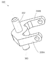
도 2는 도 1a의 요크(yoke)를 예시한다.
도 3a는 도 1a의 툴의 제 1 케이블의 라우팅(routing)을 예시한다.
도 3b는 도 1a의 툴의 제 2 케이블의 라우팅을 예시한다.
도 4a는 툴을 위한 꼬임형 스트링 기반 드라이브 메커니즘의 일 실시예를 개략적으로 예시한다.
도 4b는 꼬임형 스트링 기반 드라이브 메커니즘의 전환 블록의 일 실시예를 개략적으로 예시한다.
도 4c는 꼬임형 스트링 기반 드라이브 메커니즘의 일 실시예를 개략적으로 예시한다.
도 4d는 케이블 기반 드라이브 메커니즘의 일 실시예를 개략적으로 예시한다.
도 5a는 리스트 및 엔드 이펙터를 포함하는 툴의 일 실시예를 예시한다.
도 5b는 도 5a의 툴의 로커 메커니즘을 예시한다.
도 5c는 도 5a의 툴에 대한 제 1 케이블의 케이블 라우팅을 개략적으로 예시한다.
도 5d는 도 5a의 툴에 대한 제 2 케이블의 케이블 라우팅을 개략적으로 예시한다.
도 5e는 로커 메커니즘을 개략적으로 예시한다.
도 6a는 셔틀 메커니즘을 갖는 툴의 원위 부분을 예시한다.
도 6b는 도 6a의 툴에 대한 제 1 케이블의 케이블 라우팅을 개략적으로 예시한다.
도 6c는 도 6a의 툴에 대한 제 2 케이블의 케이블 라우팅을 개략적으로 예시한다.
도 6d는 셔틀 메커니즘을 개략적으로 예시한다.
도 7a는 리스트의 일 실시예를 예시한다.
도 7b는 도 7a의 리스트의 정면도를 예시한다.
도 8a는 가요성 섹션을 갖는 툴의 실시예를 예시한다.
도 8b는 도 8a의 가요성 섹션을 예시한다.
도 8c는 가요성 섹션의 일 실시예를 예시한다.
도 8d는 가요성 섹션의 일 실시예를 예시한다.
도 9a는 가요성 섹션의 일 실시예를 예시한다.
도 9b는 도 9a의 가요성 섹션을 예시한다.
도 9c는 가요성 섹션의 척추부를 예시한다.
도 10은 하이퍼덱스트러스(hyperdexterous) 수술 시스템을 예시한다.
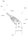
도 11은 하이퍼덱스트러스 수술용 툴에 연결된 하이퍼덱스트러스 수술용 암(arm)을 예시한다.
도 12a는 리스트 및 엔드 이펙터를 포함하는 툴의 일 실시예의 원위 단부를 예시한다.
도 12b는 도 12a의 툴을 예시한다.
도 12c는 도 12a의 툴의 각진 풀리들을 지지하는 각진 웨지(angled wedge)를 예시한다.
도 13a는 도 12a의 툴의 제 1 케이블의 라우팅을 예시한다.
도 13b는 도 12a의 툴의 제 2 케이블의 라우팅을 예시한다.
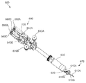
도 14a는 툴의 근위 단부의 일 실시예를 예시한다.
도 14b는 도 14a의 근위 단부에 연결된 커플링 유닛을 예시한다.
도 14c는 도 14b의 커플링 유닛의 원위 단부를 예시한다.
도 14d는 도 14b의 커플링 유닛을 예시한다.
도 14e는 도 14b의 커플링 유닛의 부분도를 예시한다.
도 15는 리스트 및 엔드 이펙터를 포함하는 툴의 일 실시예를 개략적으로 예시한다.
도 16은 리스트 및 엔드 이펙터를 포함하는 툴의 일 실시예를 개략적으로 예시한다.
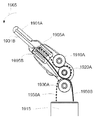
도 17a는 리스트 및 엔드 이펙터를 포함하는 툴의 일 실시예의 원위 부분을 예시한다.
도 17b는 도 17a의 툴을 예시한다.
도 17c는 도 17a의 툴을 예시한다.
도 17d는 도 17a의 툴에 대한 제 1 케이블의 케이블 라우팅을 예시한다.
도 17e는 도 17a의 툴에 대한 제 2 케이블의 케이블 라우팅을 예시한다.
도 18a는 리스트 및 엔드 이펙터를 포함하는 툴의 일 실시예의 원위 단부를 예시한다.
도 18b는 도 18a의 툴을 예시한다.
도 18c는 도 18a의 툴을 예시한다.
도 18d는 도 18a의 툴에 대한 제 1 케이블의 케이블 라우팅을 예시한다.
도 18e는 도 18a의 툴에 대한 제 2 케이블의 케이블 라우팅을 예시한다.Figure 1A illustrates distal end of one embodiment of a tool including a list and an end effector.
Figure IB illustrates the tool of Figure 1A.
Figure 2 illustrates the yoke of Figure 1A.
Figure 3a illustrates the routing of the first cable of the tool of Figure < RTI ID = 0.0 > 1a. ≪ / RTI >
Figure 3b illustrates the routing of the second cable of the tool of Figure 1a.
4A schematically illustrates one embodiment of a twisted string-based drive mechanism for a tool.
Figure 4b schematically illustrates one embodiment of a switch block of a twisted string-based drive mechanism.
Figure 4c schematically illustrates one embodiment of a twisted string-based drive mechanism.
Figure 4d schematically illustrates one embodiment of a cable-based drive mechanism.
5A illustrates an embodiment of a tool including a list and an end effector.
Figure 5b illustrates the rocker mechanism of the tool of Figure 5a.
Figure 5c schematically illustrates cable routing of the first cable to the tool of Figure 5a.
Figure 5d schematically illustrates cable routing of the second cable to the tool of Figure 5a.
Figure 5e schematically illustrates the rocker mechanism.
6A illustrates a distal portion of a tool having a shuttle mechanism.
Figure 6b schematically illustrates cable routing of the first cable to the tool of Figure 6a.
Figure 6c schematically illustrates cable routing of the second cable to the tool of Figure 6a.
Figure 6d schematically illustrates the shuttle mechanism.
Figure 7A illustrates one embodiment of a list.
Figure 7b illustrates a front view of the list of Figure 7a.
Figure 8A illustrates an embodiment of a tool having a flexible section.
Figure 8b illustrates the flexible section of Figure 8a.
Figure 8C illustrates one embodiment of a flexible section.
Figure 8d illustrates one embodiment of a flexible section.
Figure 9A illustrates one embodiment of a flexible section.
Figure 9b illustrates the flexible section of Figure 9a.
Figure 9c illustrates the vertebrae of the flexible section.
Figure 10 illustrates a hyperdexterous surgical system.
11 illustrates an arm for hyperdextrose surgery connected to a tool for hyperdextrose surgery.
12A illustrates the distal end of an embodiment of a tool including a list and an end effector.
Figure 12b illustrates the tool of Figure 12a.
Figure 12C illustrates an angled wedge supporting the angled pulleys of the tool of Figure 12A.
Figure 13A illustrates the routing of the first cable of the tool of Figure 12A.
Figure 13b illustrates the routing of the second cable of the tool of Figure 12a.
14A illustrates one embodiment of the proximal end of the tool.
Figure 14b illustrates a coupling unit connected to the proximal end of Figure 14a.
Figure 14c illustrates the distal end of the coupling unit of Figure 14b.
Figure 14d illustrates the coupling unit of Figure 14b.
Figure 14E illustrates a partial view of the coupling unit of Figure 14B.
15 schematically illustrates one embodiment of a tool including a list and an end effector.
Figure 16 schematically illustrates one embodiment of a tool including a list and an end effector.
17A illustrates a distal portion of one embodiment of a tool including a list and an end effector.
Figure 17B illustrates the tool of Figure 17A.
Figure 17c illustrates the tool of Figure 17a.
Figure 17d illustrates cable routing of the first cable to the tool of Figure 17a.
Figure 17E illustrates cable routing of the second cable to the tool of Figure 17A.
18A illustrates the distal end of one embodiment of a tool including a list and an end effector.
Figure 18b illustrates the tool of Figure 18a.
Figure 18c illustrates the tool of Figure 18a.
Figure 18d illustrates cable routing of the first cable to the tool of Figure 18a.
Figure 18E illustrates cable routing of the second cable to the tool of Figure 18A.
상용 툴들을 뛰어 넘는 다양한 이점들을 갖는 수술용 툴들과 같은 툴들의 실시예들이 이하에서 설명된다. 본원에서 설명되는 툴들의 실시예들 중 적어도 일부는 바람직하게 작업지점의 더 적은 폐색을 제공하며, 그럼으로써 집도의에게 작업지점의 개선된 시각화를 허용한다. 본원에서 설명되는 툴들의 실시예들 중 적어도 일부는, 예를 들어, 툴의 리스트의 직경을 감소시킴으로써 복잡한 수술들을 수행하기 위한 향상된 능력(예를 들어, 툴의 조작자의, 툴을 조작하는 외과의의)을 가능하게 한다. 본원에서 설명되는 툴들의 적어도 일부 실시예들은, 액세스가 제한된 영역들(예를 들어, 더 작은 작업공간)에서 작업할 수 있는 향상된 능력을 제공하며, 이는 툴의 리스트의 직경의 감소에 의해 적어도 부분적으로 가능해질 수 있다. Embodiments of tools, such as surgical tools, having various advantages over commercial tools are described below. At least some of the embodiments of the tools described herein preferably provide less obstruction of the work point, thereby allowing the elevator operator to have an improved visualization of the work point. At least some of the embodiments of the tools described herein may include, for example, an improved ability to perform complex surgeries by reducing the diameter of the list of tools (e.g., an operator of a tool, a surgeon manipulating a tool ). At least some embodiments of the tools described herein provide an enhanced ability to work in restricted areas of access (e.g., smaller workspaces), which is at least partially due to a reduction in the diameter of the list of tools . ≪ / RTI >
이하에서 개시되는 일부 실시예들에 있어, 툴이 리스트를 통해 툴 샤프트에 연결된 엔드 이펙터를 포함할 수 있으며, 여기에서 리스트는 다중-축 운동(예를 들어, 피치 및 요 움직임)을 가능하게 한다. 리스트의 크기는 바람직하게, 툴의 엔드 이펙터의 제어에 영향을 주기 위한 감소된 수의 케이블들을 사용함으로써 최적화될 수 있다. 따라서, 이렇게 최적화된 툴들이 리스트의 이러한 특징에 기인하여, 예를 들어, 최소 침습 수술 절차들에서 사용될 수 있다. 그러나, 이하에서 설명되는 전반적인 리스트가 다수의 비-수술 및 비-의료 애플리케이션들에서 또한 사용될 수 있다는 것이 이해되어야만 한다. In some embodiments described below, a tool may include an end effector coupled to a tool shaft via a list, wherein the list enables multi-axis motion (e.g., pitch and yaw motion) . The size of the list is preferably optimized by using a reduced number of cables to influence the control of the end effector of the tool. Thus, these optimized tools can be used in, for example, minimally invasive surgical procedures due to this feature of the list. It should be understood, however, that the overall list described below may also be used in a number of non-surgical and non-medical applications.
이하에서 설명되는 실시예들 중 몇몇에 있어, 툴의 리스트 및/또는 엔드 이펙터의 운동이 4개의 케이블 단부들을 제어함으로써 제어되며, 이는 몇몇 이점들을 제공한다. 하나의 이점은 툴의 리스트까지 연장하는 케이블들의 수의 감소이며, 이는 리스트의 기계적 어셈블리의 크기 및 복잡도을 최소화하는 것을 가능하게 한다. 다른 이점은, 4개의 케이블 배열이, 프리-텐셔닝(pre-tensioning)에 대한 필요성 없이 그리고 툴 리스트들의 조인트들에서의 결과적인 마찰 없이, 리스트의 각 케이블 상의 장력의 독립적인 제어를 가능하게 한다는 것이다. 각 케이블의 장력의 독립적인 제어는 또한 리스트의 조인트들에서의 가변 컴플라이언스(compliance) 및 외부 하중에 대한 증가된 감도를 가능하게 한다. 케이블들의 장력의 독립적인 제어는, 장력이 재조정될 수 있기 때문에, 툴의 마모에 대한 증가된 강건성을 추가로 허용한다. 또한, 각 케이블의 장력의 독립적인 제어는, 각 케이블이 상이한 양으로 길이를 변화시킬 수 있기 때문에, 꼬임형 스트링들과 같은 비-선형 전달체(transmission)들의 사용을 허용한다. 각 케이블의 독립적인 제어는 추가적으로, 고정된 케이블 루프들을 사용할 때 요구되는 것과 같은 모든 케이블 길이들의 합이 리스트의 운동의 범위에 걸쳐 일정할 것을 요구하지 않는 리스트 설계들을 가능하게 한다. 본원에서 설명되는 툴들의 다른 이점들이 이하에서 제공되는 상세한 설명에 기초하여 당업자들에게 자명해질 것이다.In some of the embodiments described below, the list of tools and / or the motion of the end effector is controlled by controlling the four cable ends, which provides several advantages. One advantage is a reduction in the number of cables extending to the list of tools, which makes it possible to minimize the size and complexity of the mechanical assembly of the list. Another advantage is that the four cable arrangements allow independent control of the tension on each cable of the list without the need for pre-tensioning and without the resulting friction in the joints of the tool lists will be. Independent control of the tension of each cable also allows for variable compliance at the joints of the list and increased sensitivity to external loads. Independent control of the tension of the cables further allows increased robustness to wear of the tool, since the tension can be re-adjusted. Independent control of the tension of each cable also permits the use of non-linear transmissions, such as twisted strings, because each cable can vary in length in different amounts. Independent control of each cable additionally enables list designs that do not require that the sum of all cable lengths as required when using fixed cable loops is constant over the range of movement of the list. Other advantages of the tools described herein will become apparent to those skilled in the art based on the detailed description provided below.
도 1a 내지 도 1b는 근위 단부(미도시) 및 원위 단부(31)을 갖는 툴(30)의 일 실시예를 도시하며, 여기에서 이하에서 설명되는 바와 같은 툴(30)의 케이블 라우팅 및 툴의 리스트의 구성이 바람직하게 툴의 리스트의 크기의 감소를 가능하게 한다. 일부 실시예들에 있어, 리스트의 크기의 감소는 더 간단한 케이블 라우팅에 의해 가능해지며, 이는 리스트의 곡률의 짧아진 반경을 가능하게 하고 툴의 리스트 어셈블리의 복잡도의 감소를 가능하게 한다. 일부 실시예들에 있어, 툴(30)의 리스트의 크기의 감소는 리스트의 직경의 감소를 포함할 수 있다. 1A-1B illustrate an embodiment of a
도 1a에 도시된 바와 같이, 툴(30)의 원위 단부(31)는 툴(30)의 샤프트(30A)에 연결된 요크(360)를 가질 수 있다. 요크(360)는 축(380)(도 2에 도시된 바와 같은)을 따라 연장하는 연장된 차축(axle)(332)을 통해 제 2 요크(330)에 이동가능하게 연결된다. 일 실시예에 있어, 연장된 차축(332)은 착탈가능할 수 있거나 또는 제 2 요크(330)와 일체적으로 형성될 수 있다. 다른 실시예들에 있어, 연장된 차축(332)이 착탈가능하거나 또는 요크(360)와 일체적으로 형성될 수 있으며, 그 결과 차축(332)의 부분들이 요크(360)의 암들에 부착되고, 요크(330)가 차축(332)의 상기 부분들 사이에 삽입될 수 있다. 일 실시예에 있어, 툴(30)은 수술용 툴일 수 있다. 다른 실시예에 있어, 툴(30)은 비-수술용 툴일 수 있다. The
도 1b에 도시된 바와 같이, 제 2 요크(330)의 연장된 차축(332)이, 풀리들(340A, 340B, 350A, 350B)이 연장된 차축(332)의 축(380)을 따라 배열되도록, 풀리들(340A, 340B, 350A, 350B)과 연결된다. 풀리들(340A, 340B, 350A, 350B)은 풀리들(340B, 350B)의 제 1 세트 및 풀리들(340A, 350A)의 제 2 세트로 배열된다. 풀리들(340B, 350B)의 제 1 세트는 요크(330)의 일 측 상에 있으며, 풀리들(340A, 350A)의 제 2 세트는 요크(330)의 다른 측 상에 있다. 풀리들(340A, 350A)은 외부 풀리들이며, 풀리들(340B, 350B)은 내부 풀리들이다. The
용어들 "내부(inner)" 및 "외부(outer)"는 도면들에 도시되는 바와 같은 풀리들의 배향을 나타낸다. 본원에서 사용되는 바와 같은, 플리들의 "세트"는 임의의 수의 풀리들을 포함할 수 있다. 풀리들의 세트가 하나의 풀리를 포함할 수 있다. 풀리들의 세트는 2개 이상의 풀리(예를 들어, 2개, 3개, 4개, 5개, 6개의 풀리들 등)을 포함할 수 있다.The terms "inner" and "outer" refer to the orientation of the pulleys as shown in the figures. As used herein, a "set" of flies can include any number of pulleys. A set of pulleys may include a single pulley. The set of pulleys may include two or more pulleys (e.g., two, three, four, five, six pulleys, etc.).
계속해서 도 1a 내지 도 1b를 참조하면, 제 2 요크(330)가 풀리들의 제 3 세트(320A, 320B)에 연결된다. 풀리들의 제 3 세트(320A, 320B)는 축(380)으로부터 소정의 거리로(예를 들어, 원위로) 이격될 수 있다. 풀리들의 제 3 세트(320A, 320B)는 제 2 요크(330)의 암들(330A, 330B)에 연결되며, 암들(330A, 330B)을 통해 규정된 축(370)을 따라 배열된다. 일 실시예에 있어, 제 2 요크(330)는 축(370)을 따라 연장하는 연장된 차축을 포함할 수 있다. 일 실시예에 있어, 연장된 차축은 착탈가능하게 제 2 요크(330)에 연결될 수 있다. 다른 실시예들에 있어, 연장된 차축이 착탈가능하거나 또는 제 2 요크(330)와 일체적으로 형성될 수 있으며, 그 결과 차축의 부분들이 제 2 요크(330)의 암들에 부착되고, 풀리들(320A, 320B)이 차축의 상기 부분들 사이에 삽입될 수 있다. 일 실시예에 있어, 축(370)이 축(380)에 대하여 각도를 가질 수 있다. 다른 실시예에 있어, 축(370)이 축(380)에 직교할 수 있다. 풀리들(340B, 350B)의 제 1 세트가 풀리들(320A, 320B)의 제 3 세트에 직교할 수 있다. 풀리들(340A, 350A)의 제 2 세트가 또한 풀리들(320A, 320B)의 제 3 세트에 직교할 수 있다.With continued reference to FIGS. 1A-1B, a
그래스퍼(310)의 한 쌍의 조(jaw)들(310A, 310B)이 풀리들(320A, 320B)의 제 3 세트를 통해 제 2 요크(330)에 연결될 수 있으며, 그 결과 조들(310A, 310B)이 축(370)에 대해 회전할 수 있다. 일 실시예에 있어, 조(310A)가 풀리(320A)에 연결된다. 다른 실시예에 있어, 조(310A)가 풀리(320A)와 일체로 형성될 수 있다. 유사하게, 일 실시예에 있어, 조(310B)가 풀리(320B)에 연결된다. 다른 실시예에 있어, 조(310B)가 풀리(320b)와 일체로 형성될 수 있다. 조(310A) 및 풀리(320A)가 축(370)에 대해 회전할 수 있다. 유사하게, 조(310B) 및 풀리(320B)가 축(370)에 대해 회전할 수 있다. 예시된 실시예에 있어, 그래스퍼(310)는 툴(30)의 엔드 이펙터이다. 그러나, 다른 실시예들에 있어, 엔드 이펙터는 수술 절차들(예를 들어, 경피적인 수술 절차들)에서 사용되는 메커니즘들과 같은 다른 적절한 메커니즘들일 수 있다.A pair of
툴(30)은 축(370)에 대하여 다양한 방식들로 조들(310A, 310B) 중 하나 또는 둘 모두를 움직이도록 구동될 수 있다. 예를 들어, 조들(310A, 310B)이 서로에 대하여 열리고 닫힐 수 있다. 조들(310A, 310B)이 또한, 그래스퍼(310)의 요 운동을 제공하기 위해 한 쌍으로써 함께 회전하도록 구동될 수 있다. 추가적으로, 툴(30)은 축(380)에 대하여 조들(310A, 310B)의 다양한 유형들의 운동들에 영향을 미치도록 구동될 수 있다. 예를 들어, 제 2 요크(330), 풀리들(320A, 320B), 및 조들(310A, 310B)이 그래스퍼(310)의 피치 운동을 제공하기 위하여 축(380)에 대하여 회전할 수 있다.The
도 3a 내지 도 3b는 툴(30)의 케이블들의 배향의 일 실시예를 도시한다. 바람직하게는, 이하에서 설명되는 바와 같이, 케이블들의 라우팅이 그래스퍼(310)의 운동이 4개의 독립적인 케이블 단부들 또는 2개의 케이블 루프들의 구동을 통해 제어될 수 있게 하며, 이는 그래스퍼(310)를 제어하는데 사용되는 케이블들의 수가 상용 툴들(전형적으로 6개의 케이블 단부들을 갖는 3개의 케이블 루프들을 사용하는)에 비해 감소될 수 있게 하고, 그럼으로써 바람직하게 툴(30)의 리스트의 크기 및 복잡도가 이상에서 논의된 바와 같이 감소될 수 있게끔 한다. 이러한 유리한 특징(예를 들어, 단지 4개의 독립적인 케이블 단부들 또는 2개의 케이블 루프들만의 구동을 통해 엔드 이펙터의 움직임을 제어하기 위한 능력)이 본 발명의 실시예들에서 설명되는 툴들에 존재한다.Figs. 3A-3B illustrate an embodiment of the orientation of the cables of the
도 3a 내지 도 3b를 참조하면, 풀리들(320A, 320B)의 제 3 세트가 각기 포켓(pocket) 또는 리세스(recess)를 포함할 수 있다. 일 실시예에 있어, 포켓은 비드(315A, 315B)를 적어도 부분적으로 유지하도록 크기가 결정된다. 비드(315B)가 도 3a 내지 도 3b에 도시되어 있지 않지만, 이러한 도면들에 도시된 비드(315A)와 유사할 수 있다. 비드(315A)가 제 1 케이블(390A)에 부착될 수 있으며, 비드(315B)가 제 2 케이블(390B)에 부착될 수 있고, 여기에서 케이블들(390A, 390B) 각각이 2개의 독립적인 케이블 단부들을 갖는다. 비드들(315A, 315B)은, 케이블들(390A, 390B)이 풀리들(320A, 320B)에 대하여 미끄러지거나 또는 슬라이딩하는 것을 금지(예를 들어, 방지)하기 위한 것과 같은 방식으로 케이블들(390A, 390B)에 부착된다. 케이블들(390A, 390B)이 비드들(315A, 315B)에 고정적으로(immovably) 연결된다. 일 실시예에 있어, 비드들(315A, 315B)이 케이블들(390A, 390B)과 일체로 형성될 수 있다. 다른 실시예에 있어, 비드들(315A, 315B)이 케이블들(390A, 390B) 상으로 크림핑(crimp)될 수 있다.Referring to Figures 3A-B, the third set of
도 3a는 도 3a에서 점선들로 도시된 제 1 케이블(390A)의 케이블 라우팅을 도시한다. 제 1 케이블(390A)은 툴(30)의 근위 단부에서 발원(originate)하며, 툴 샤프트(30A)를 통해 연장한다. 제 1 케이블(390A)은 요크(360)의 홀 또는 개구부(30C)(도 1a 참조)를 통해 연장한다. 제 1 케이블(390A)이 풀리들(340B, 350B)의 제 1 세트의 하나의 풀리를 적어도 부분적으로 둘러 감는다. 제 1 케이블(390A)이 풀리들(320A, 320B)의 제 3 세트의 하나의 풀리를 적어도 부분적으로 둘러 감는다. 제 1 케이블(390A)이 풀리들(340A, 350B)의 제 2 세트의 하나의 풀리를 적어도 부분적으로 둘러 감는다. 일부 실시예들에 있어, 도 3a에 도시된 바와 같이, 제 1 케이블(390A)이 풀리(340B), 풀리(320A), 및 풀리(340A)를 적어도 부분적으로 둘러 감는다. 그런 다음, 제 1 케이블(390A)은 요크(360)의 다른 홀 또는 개구부(30B)(도 1a 참조)를 통과하며, 툴 샤프트(30A)를 통해 툴(30)의 근위 단부로 복귀한다.FIG. 3A illustrates cable routing of the
일부 실시예들에 있어, 제 1 케이블(390A)이 풀리(320A)에 연결될 수 있는 2개의 케이블들(390A' 및 390A'')(미도시)로 대체될 수 있다(예를 들어, 여기에서 케이블(390A)이 2개의 별개의 케이블 부분들(390A' 및 390A'')로 대체된다). 케이블(390A')이 풀리들(340B, 350B)의 제 1 세트의 하나의 풀리를 적어도 부분적으로 둘러 감으며, 케이블(390A'')이 풀리들(340A, 350A)의 제 2 세트의 하나의 풀리를 적어도 부분적으로 둘러 감는다. 이러한 실시예에 있어, 케이블들(390A', 390A'')이 풀리들(320A, 320B)의 제 3 세트의 하나의 풀리의 하나의 면만을 가로지른다. 이러한 실시예에 있어, 케이블들(390A', 390A'')의 각각이 풀리(320A)의 일 측만을 가로지른다. 일부 실시예들에 있어, 케이블들(390A', 390A'')이 풀리(320A)에 고정적으로 연결된다(예를 들어, 비드(315A)를 통해). 예를 들어, 이상에서 논의된 바와 같이, 비드(315A)가 케이블들(390A', 390A'')의 각각의 단부 상에 크림핑될 수 있으며, 비드(315A)가 풀리(320A)의 포켓 내에 유지되고, 그럼으로써 케이블들(390A', 390A'')을 풀리(320A)에 고정적으로 연결한다. 풀리(320A)에 부착된 2개의 독립적인 케이블들(390A', 390A'')을 갖는 것 또는 풀리(320A)에 부착된 하나의 케이블(390A)를 갖는 것의 효과가 동일하다.In some embodiments, a
도 3b는 제 2 케이블(390B)을 점선으로 도시한다. 제 2 케이블(390B)은 툴(30)의 근위 단부에서 발원하며, 툴 샤프트(30A)를 통해 연장한다. 제 2 케이블(390B)은 요크(360)의 홀 또는 개구부(30C)(도 1a 참조)를 통해 연장한다. 제 2 케이블(390B)이 풀리들(340B, 350B)의 제 1 세트의 하나의 풀리를 적어도 부분적으로 둘러 감는다. 제 2 케이블(390B)이 풀리들(320A, 320B)의 제 3 세트의 하나의 풀리를 적어도 부분적으로 둘러 감는다. 제 2 케이블(390B)이 풀리들(340A, 350A)의 제 2 세트의 하나의 풀리를 적어도 부분적으로 둘러 감는다. 일부 실시예들에 있어, 도 3b에 도시된 바와 같이, 제 2 케이블(390B)이 풀리(350B), 풀리(320B), 및 풀리(350A)를 적어도 부분적으로 둘러 감는다. 그런 다음, 제 2 케이블(390B)은 요크(360)의 홀 또는 개구부(30B)(도 1a 참조)를 통과하며, 툴 샤프트(30A)를 통해 툴(30)의 근위 단부로 복귀한다.FIG. 3B shows the
일부 실시예들에 있어, 제 2 케이블(390B)이, 케이블들(390A' 및 390A'')에 대해 이상에서 설명된 것과 유사한 방식으로, 풀리(320B)에 연결될 수 있는 2개의 케이블들(390B' 및 390B'')(미도시)로 대체될 수 있다. 따라서, 일부 실시예들에 있어, 4개의 독립적인 케이블들(390A', 390A'', 390B' 및 390B'')이 사용될 수 있다. 예를 들어, 일 실시예에 있어, 케이블(390B')이 풀리들(340B, 350B)의 제 1 세트의 하나의 풀리를 적어도 부분적으로 둘러 감으며, 케이블(390B'')이 풀리들(340A, 350A)의 제 2 세트의 하나의 풀리를 적어도 부분적으로 둘러 감는다. 이러한 실시예에 있어, 케이블들(390B', 390B'')이 풀리들(320A, 320B)의 제 3 세트의 하나의 풀리의 일 측만을 가로지른다. 이러한 실시예에 있어, 케이블들(390A', 390A'')의 각각이 풀리(320B)의 일 측만을 가로지른다. 일부 실시예들에 있어, 케이블들(390B', 390B'')이 풀리(320B)에 고정적으로 연결된다(예를 들어, 비드(315B, 미도시)를 통해). 예를 들어, 이상에서 논의된 바와 같이, 비드(315B)가 케이블들(390B', 390B'')의 각각의 단부 상에 크림핑될 수 있으며, 비드(315B)가 풀리(320B)의 포켓 내에 유지되고, 그럼으로써 케이블들(390B', 390B'')을 풀리(320B)에 고정적으로 연결한다. 풀리(320B)에 부착된 2개의 독립적인 케이블들(390B', 390B'')을 갖는 것 또는 풀리(320B)에 부착된 하나의 케이블(390B)를 갖는 것의 효과가 동일하다. In some embodiments, a
툴(30)은, 풀리들(340A, 340B, 350A, 350B, 320A, 320B) 중 하나 이상에 운동을 부여(impart)하여 조들(310A, 310B) 중 하나 또는 둘 모두 및/또는 요크(330) 상에 운동을 부여함으로써, 그래스핑(예를 들어, 축(370)에 대하여 조들이 독립적으로 회전하는 것), 요(예를 들어, 조들이 축(370)에 대하여 함께 회전하는 것), 및 피치(예를 들어, 조들이 축(380)에 대하여 회전하는 것)와 같은 다양한 방식들로 조들(310A, 310B)을 움직이도록 구동될 수 있다. 툴(30)이 그래스퍼(310)의 움직임에 영향을 주는 2개의 케이블들(390A, 390B)을 갖는 일 실시예에 있어, 각 케이블(390A, 390B)은, 풀리들(320A, 320B)의 제 3 세트 및 조들(310A, 310B)에 운동을 부여하기 위해 독립적으로 제어되거나 또는 인장(tension)될 수 있는 2개의 독립적인 케이블 단부들을 갖는다. 예를 들어, 풀리(320A) 및 조(310A)의 운동이 케이블(390A)의 2개의 케이블 단부들로 제어될 수 있다. 유사하게, 풀리(320B) 및 조(310B)의 운동이 케이블(390B)의 2개의 케이블 단부들로 제어될 수 있다. 도 1 내지 도 3b의 시스템이 4개의 케이블 단부들을 갖는다. 4개의 케이블 단부들이 풀리들(340A, 340B, 350A, 350B, 320A, 320B) 중 하나 이상에 운동을 부여하기 위해 제어될 수 있다. 4개의 케이블 단부들(각 케이블(390A, 390B)에 대한 쌍)이, 이하에서 추가로 설명되는 바와 같이, 툴(30)의 근위 단부(32)에 인접한 모터들(미도시)에 연결될 수 있다. 다른 실시예들에 있어, 4개의 케이블 단부들(각 케이블(390A, 390B)에 대한 한 쌍)이 툴 샤프트(30A)를 따라 임의의 거리에 위치된 모터들에 연결될 수 있다.The
툴(30)이 그래스퍼(310)의 움직임에 영향을 주는 4개의 케이블들(390A', 390A'', 390B', 390B'')을 갖는 다른 실시예에 있어, 각 케이블(390A', 390A'', 390B', 390B'')은, 풀리들(320A, 320B)의 제 3 세트 중 하나 또는 둘 모두 및/또는 요크(330)에 운동을 부여하기 위해 독립적으로 제어되거나 또는 인장될 수 있는 1개의 독립적인 케이블 단부를 갖는다. 독립적인 케이블 단부들이 자유(free) 케이블 단부들(예를 들어, 단부들이 비드(315A, 315B)에 연결되지 않은)로서 간주될 수 있다. 풀리(320A)의 운동이 케이블들(390A', 390A'')의 독립적인 케이블 단부들에 의해 제어될 수 있다. 풀리(320B)의 운동은 케이블들(390B', 390B'')의 독립적인 케이블 단부들에 의해 제어될 수 있다. 도 1 내지 도 3b의 시스템이 4개의 독립적인 케이블 단부들을 갖는다. 4개의 케이블 단부들이 풀리들(340A, 340B, 350A, 350B, 320A, 320B) 중 하나 이상에 운동을 부여하고, 그럼으로써 조들(310A, 310B) 중 하나 또는 둘 모두 및/또는 요크(330)에 운동을 부여하기 위해 제어될 수 있다. 4개의 케이블 단부들(각 케이블(390A', 390A'', 390B', 390B'')에 대한 단부)이 툴(30)의 근위 단부(미도시) 근처에 위치되거나 또는 툴 샤프트(30A)를 따라 임의의 거리에 위치될 수 있다.390A ', 390B ', 390B ' ' ' affecting the movement of the
일부 실시예들에 있어, 축(380)에 대한 요크(330) 및 조들(310A, 310B)의 피치 운동이 하나의 케이블(예를 들어, 390A)의 두 개의 단부들을 인장하고 다른 케이블(예를 들어, 390B)의 두 개의 단부들을 이완시킴으로써 달성된다. 예를 들어, 도 3a 내지 도 3b를 참조하면, 페이퍼(paper)의 평면 밖으로 조들(310A, 310B)를 피치하기 위하여, 케이블(390A)의 단부들 둘 모두가 인장되며, 케이블(390B)의 단부들 둘 모두가 이완된다. 페이퍼의 평면 내로 조들을 피치하기 위하여, 케이블(390A)의 단부들 둘 모두가 이완되며, 케이블(390B)의 단부들 둘 모두가 인장된다.In some embodiments, the pitch movement of the
일부 실시예들에 있어, 축(370)에 대한 그래스퍼(310)의 조들(310A, 310B))의 요 운동이 동일한 방향으로 풀리들(320A, 320B)을 움직임으로써 달성된다. 예를 들어, 도 3a를 참조하면, 조들(310A, 310B)을 상향으로 요(yaw)하기 위하여, 풀리들(320A, 320B) 둘 모두가 반시계 방향으로 이동되어야만 한다. 풀리들(340B, 350B)의 제 1 세트의 하나의 풀리에 연결된 케이블(390A)의 단부가 인장되며, 풀리들(340B, 350B)의 제 1 세트의 하나의 풀리에 연결된 케이블(390B)의 단부가 인장된다. 도 3a에서, 340B에 연결된 케이블(390A)의 단부, 및 350B에 연결된 케이블(390B)의 단부가 인장된다. 케이블들(390A, 390B)의 다른 단부들은 이완된다. 따라서, 조들(310A, 310B)이 축(370)에 대하여 상향으로 회전할 것이다. 조들(310A, 310B)을 하향으로 요하기 위하여, 풀리들(320A, 320B) 둘 모두가 시계 방향으로 이동되어야만 한다. 풀리들(340A, 350A)의 제 2 세트의 하나의 풀리에 연결된 케이블(390A)의 단부 및 풀리들(340A, 350A)의 제 2 세트의 하나의 풀리에 연결된 케이블(390B)의 단부가 인장된다. 도 3a 내지 도 3b에서, 340A에 연결된 케이블(390A)의 단부, 및 350A에 연결된 케이블(390B)의 단부가 인장된다. 케이블들(390A, 390B)의 다른 단부들은 이완된다. 케이블들(390A, 390B)의 인장 및 이완의 이러한 조합이 조들(310A, 310B)이 축(370)에 대하여 하향으로 회전하게끔 할 것이다.In some embodiments, the yaw movement of the
조들(310A, 310B)이, 예를 들어, 그래스핑 액션(action), 릴리즈 액션, 또는 가위질 운동에 영향을 주기 위하여, 서로에 대해 움직여질 수 있다. 조들(310A, 310)을 서로를 향하여 이동시키기 위해, 풀리(320A)가 반시계 방향으로 움직일 수 있고 풀리(320B)가 시계 방향으로 움직일 수 있다. 이러한 운동을 달성하기 위하여, 풀리들(340B, 350B)의 제 1 세트의 하나의 풀리에 연결된 케이블(390A)의 단부 및 풀리들(340A, 350A)의 제 2 세트의 하나의 풀리에 연결된 케이블(390B)의 단부가 인장된다. 도 3a 내지 도 3b에서, 340B에 연결된 케이블(390A)의 단부, 및 350A에 연결된 케이블(390B)의 단부가 인장된다. 케이블들(390A, 390B)의 다른 단부들은 이완된다. 케이블들(390A, 390B)의 인장 및 이완의 이러한 조합이 조들(310A, 310B)이 축(370)에 대하여 서로를 향하여 회전하게끔 할 것이다. The
조들(310A, 310)을 떨어지게 이동시키기 위해, 풀리(320A)가 시계 방향으로 움직일 수 있고 풀리(320B)가 반시계 방향으로 움직일 수 있다. 풀리들(340A, 350A)의 제 2 세트의 하나의 풀리에 연결된 케이블(390A)의 단부 및 풀리들(340B, 350B)의 제 1 세트의 하나의 풀리에 연결된 케이블(390B)의 단부가 인장된다. 도 3a 내지 도 3b에서, 340A에 연결된 케이블(390A)의 단부, 및 350B에 연결된 케이블(390B)의 단부가 인장된다. 케이블들(390A, 390B)의 다른 단부들은 이완된다. 케이블들(390A, 390B)의 인장 및 이완의 이러한 조합이 조들(310A, 310B)이 축(370)에 대하여 서로로부터 멀어지도록 회전하게끔 할 것이다. To move the
각 케이블 단부에 대하여 상이한 양의 장력을 인가함으로써 조들(310A, 310B)이 서로를 향하여 또는 서로로부터 멀어지도록 이동될 수 있다. 장력의 다양한 양들을 인가함으로써, 조들(310A, 310B)이 상이하게 요할 것이며, 이는 그래스핑 또는 릴리즈 액션을 효율적으로 에뮬레이션(emulate)한다. 움직임의 3개의 모드들(피치, 요 및 그래스핑 액션) 모두가 인장 및 이완되는 케이블 단부들을 변화시킴으로써, 및/또는 각 케이블 단부에 인가되는 장력 및 이완의 양을 변화시킴으로써 획득될 수 있다. 특정 라우팅 구성이 도 1a 내지 도 3b에 설명되었지만, 다른 라우팅 구성들이 가능하다. 예를 들어, 케이블(390A)이 이상에서 설명된 바와 같은 외부 풀리(340B) 둘레를 감는 대신 내부 풀리(350B) 둘레를 감을 수 있다. By applying different amounts of tension to each cable end, the
일부 실시예들에 있어, 툴의 리스트 및/또는 엔드 이펙터의 운동이 하나 이상의 꼬임형 스트링들로 영향을 받을 수 있다. 꼬임형 스트링 쌍의 길이가 단축되고 그에 따라 꼬임형 스트링 쌍을 따라 장력을 생성하도록, 꼬임형 스트링 쌍이 2개의 컴포넌트 스트링들을 서로 둘러 꼬는 것의 원리 상에 작용한다. 유사하게, 꼬임형 스트링 상의 컴포넌트 스트링들이 감기지 않을 때, 꼬임형 스트링 쌍의 길이가 각 컴포넌트 스트링의 자연적인 길이에 접근한다. 도 4a 내지 도 4d는, 꼬임형 스트링들 및 케이블들로, 툴(30)과 같은 툴을 제어하는 드라이브 메커니즘들 및 방법들의 실시예들을 도시한다. 도 4a는 툴의 케이블을 제어하기 위한 드라이브 메커니즘(500A)을 개략적으로 도시한다. 시스템은 2개의 케이블들(521, 522)을 포함한다. 각 케이블(521, 522)은 풀리(510A, 510B)와 연관된다. 풀리들(510A, 510B)이 드라이브되는 대상물들이다. 하나의 풀리(510B)가 도시되었지만, 케이블(521)이 복수의 풀리들과 연관될 수 있다. 유사하게, 하나의 풀리(510A)가 도시되었지만, 케이블(522)이 복수의 풀리들과 연관될 수 있다. 각 케이블(521, 522)이 2개의 케이블 단부들을 갖는다. 각 케이블 단부가 전환 블록(530A, 530B, 530C, 530D)에 연결된다. 각 전환 블록(530A, 530B, 530C, 530D)이 꼬임형 스트링 쌍(520A, 520B, 520C, 520D)에 연결된다. 각 꼬임형 스트링 쌍(520A, 520B, 520C, 520D)이 모터(515A, 515B, 515C, 515D)에 연결된다.In some embodiments, the list of tools and / or the motion of the end effector may be influenced by one or more twisted strings. A twisted string pair acts on the principle of twisting the two component strings together to shorten the length of the twisted string pair and thereby generate the tension along the twisted string pair. Similarly, when the component strings on the twisted string are not rolled, the length of the twisted string pair approaches the natural length of each component string. 4A-4D illustrate embodiments of drive mechanisms and methods for controlling a tool, such as
도 4a를 계속해서 참조하면, 각 꼬임형 스트링 쌍(520A, 520B, 520C, 520D)이 축 방향(axial) 모터(515A, 515B, 515C, 515D)에 의해 드라이브된다. 예를 들어, 꼬임형 스트링 쌍(520A)이 축 방향 모터(515A)에 의해 드라이브되며, 꼬임형 스트링 쌍(520B)이 축 방향 모터(515B)에 의해 드라이브된다. Continuing with FIG. 4A, each
전환 블록들(530A, 530B, 530C, 530D)이 꼬임형 스트링 쌍들(520A, 520B, 520C, 520D)과 케이블들(521, 522) 사이의 전환을 제공한다. 도 4a에 도시된 바와 같이, 케이블(521)이 전환 블록들(530B 및 530C) 사이에서 연장한다. 케이블(522)은 전환 블록들(530A 및 530D) 사이에서 연장한다. 꼬임형 스트링 쌍들(520A, 520B, 520C, 520D)은, 그 위에서 꼬임형 스트링 쌍들이 굽혀져야 할 필요가 있는 표면(예를 들어, 풀리들(510A, 510B)의 만곡된 표면)과 접촉할 때 예측할 수 없는 거동을 나타낼 수 있으며, 그 결과 전환 블록들(530A, 530B, 530C, 530D)이 케이블들(521, 522)만이 풀리들(510A, 510B)의 만곡된 표면들과 접촉하도록 꼬임형 스트링 쌍들(520A, 520B, 520C, 520D)과 케이블들(521, 522) 사이의 전환을 제공한다.The conversion blocks 530A, 530B, 530C and 530D provide a transition between the twisted string pairs 520A, 520B, 520C and 520D and the
도 4b는 전환 블록(530A)을 도시한다. 일 실시예에 있어, 4개의 전환 블록들(530A, 530B, 530C 및 530D) 모두가 전환 블록(530A)과 유사한 특징들을 갖는다. 꼬임형 스트링 쌍(520A)이 종료 블록(531A)에 연결된다. 케이블(522)이 또한 종료 블록(531A)에 연결된다. 종료 블록(531A)은 페그(peg)(532A)에 고정적으로 연결된다. 일 실시예에 있어, 종료 블록(531A)이 페그(532A)와 일체로 형성될 수 있다. Figure 4B shows a
페그(532A)가, 꼬임형 스트링 쌍(520A)의 길이가 단축되거나 또는 증가되도록, 화살표(534A)를 따라 베이스 블록(533A) 내의 슬롯(535A) 내에서 슬라이드 할 수 있다. 예시된 실시예에 있어, 페그(532A) 및 슬롯(535A) 둘 모두가 베이스 블록(533A)의 내부 표면들이며, 점선 형태로 도시된다. 페그(532A) 및 슬롯(535A)이 바람직하게 종료 블록(531A)이 꼬임형 스트링 쌍(520A)의 영향에 기인하여 회전하거나 또는 스핀(spin)하는 것을 방지한다. 꼬임형 스트링 쌍(520A)의 길이가 감소될 때, 종료 블록(531A)에 연결된 페그(532A)가 베이스 블록(533A) 내의 슬롯(535A) 내에서 슬라이드하며, 종료 블록(531A)이 결과적으로 케이블(522)을 끌어 당긴다. 케이블(522)이 풀리(510A)를 회전시키기 위하여 이러한 장력을 풀리(510A)로 전달한다.
계속해서 도 4a를 참조하면, 꼬임형 스트링 쌍(520A)이 꼬임형 스트링 쌍(520C)에 대하여 이동된다. 모터(515A)가 모터(515A)에 부착된 꼬임형 스트링 쌍(520A)을 감으며, 그럼으로써 꼬임형 스트링 쌍(520A)의 길이를 단축시킨다. 모터(515C)가 모터(515C)에 부착된 꼬임형 스트링 쌍(520C)을 풀며, 그럼으로써 꼬임형 스트링 쌍(520C)의 길이를 연장한다. 이러한 2개의 액션들이 케이블(522)이 모터(515A)를 향해 끌어 당겨지게끔 하며, 이는 풀리(510A)가 반시계 방향으로 회전하게끔 한다. 풀리(510A)를 시계 방향으로 움직이게 하기 위하여, 모터(515A)가 꼬임형 스트링 쌍(520A)을 풀고 모터(515C)가 꼬임형 스트링 쌍(520C)을 감을 것이다. 모터들(515B, 515D)이 유사한 방식으로 케이블(521) 및 풀리(510B)를 움직일 수 있다. 케이블들(521, 522)이 비드들(315A, 315B)과 유사한 비드에 연결될 수 있으며, 비드가 풀리들(510A, 510B)에 연결될 수 있다(예를 들어, 이상에서 논의된 방식으로, 풀리들(510A, 510B)의 포켓들 내에 유지될 수 있다). 추가적으로, 다른 실시예에 있어, 4개의 케이블들이 풀리들(510A, 510B) 상의 비드들과 전환 블록(530A, 530B, 530C, 530D) 사이에서 연장하도록, 케이블들(521, 522)의 각각이 2개의 독립적인 케이블들로 대체될 수 있다.Continuing with reference to FIG. 4A,
풀리들(510A, 510B)을 드라이브하는 다른 모드에서, 꼬임형 스트링 쌍들 둘 모두가 균등하게 감길 수 있다. 예를 들어, 모터들(515A, 515C)이 꼬임형 스트링 쌍들(520A, 520C) 둘 모두를 감을 수 있으며, 반면 모터들(515B, 515D)이 구동되지 않는다. 이러한 경우에 풀리(510A)가 회전하지 않지만 모터들(515A, 515C)의 방향에서 당김력(pulling force)을 경험할 것이며, 이는 화살표(523)을 따라 페이지 내로의 요 운동을 초래한다. 대신에 모터들(515B, 515D)이 꼬임형 스트링 쌍들(520B, 530D)를 감기 위하여 구동되고 반면 모터들(510A, 515C)이 구동되지 않는 경우, 풀리(510B)가 회전하지 않지만 모터들(515B, 515D)의 방향에서 당김력을 경험할 것이며, 이는 화살표(523)에 반대되는 방향으로 페이지 밖으로의 요 운동을 초래한다. 이상의 설명에 추가로, 요 운동의 양이 꼬임형 스트링 쌍들이 감기는 양에 의해 제어될 수 있다.In other modes of driving the
도 4c는 툴(30)과 같은 툴을 제어하기 위한 드라이브 메커니즘(500B)을 개략적으로 도시한다. 시스템은 풀리(580)와 연관된 케이블(570)을 포함한다. 예시된 실시예에 있어, 케이블(570)이 이하에서 추가로 논의되는 바와 같이 하나 이상의 꼬임형 스트링 쌍들을 규정한다. 오로지 하나의 풀리(580)가 도시되었지만, 케이블이 이상에서 논의된 바와 같이 복수의 풀리들과 연관될 수 있다. 추가적으로, 시스템은 제 2 풀리(미도시)와 연관된 제 2 케이블(미도시)을 포함할 수 있다. 예시된 실시예에 있어, 풀리(580)가 드라이브되는 대상물이다. 이상의 실시예들에서 설명된 바와 같이, 케이블(570)이 2개의 전환 블록들(565A, 565B)에 연결된다.Figure 4c schematically illustrates a
각 전환 블록(565A, 565B)이 꼬임형 스트링 쌍(560A, 560B)에 연결된다. 각 꼬임형 스트링 쌍(560A, 560B)이 루프(555A, 555B)를 형성한다. 각 루프(555A, 555B)가 모터(550A, 550B)에 연결된다. 꼬임형 스트링 쌍(560A)은 자체적으로 이중화된(doubled) 케이블(570)에 의해 규정된다. 다시 말해서, 케이블(570)이 전환 블록(565A)에 연결되며(예를 들어, 전환 블록(530A)과 유사하게, 페그가 전환 블록(565A)의 베이스 블록 상에서 슬라이드할 수 있지만 회전하지는 않도록, 전환 블록(565A)의 페그에 연결되며), 꼬임형 스트링 쌍(560A) 및 루프(555A)를 규정하기 위해 전환 블록(565A)를 지나 연장하고, 다시 전환 블록(565A)에 연결된다. 유사하게, 꼬임형 스트링 쌍(560B)이 자체적으로 이중화된 케이블(570)에 의해 규정된다. 다시 말해서, 케이블(570)이 전환 블록(565B)에 연결되고, 꼬임형 스트링 쌍(560B) 및 루프(555B)를 규정하기 위해 전환 블록(565B)을 지나 연장하며, 다시 전환 블록(565B)에 연결된다.Each switching
모터들(550A 및 550B)이 루프들(555A, 555B)을 감거나 또는 풀 수 있으며, 결과적으로 꼬임형 스트링 쌍(560A, 560B)을 감거나 또는 풀 수 있다. 따라서, 케이블(570)이 전환 블록들(565A, 565B)의 종료 블록의 양 측 둘 모두로부터 연장한다. 케이블(570)이 비드(575)에 부착될 수 있으며, 이는 도 3a의 비드(315A)에 대한 케이블들의 부착과 유사할 수 있다. 드라이브 메커니즘(500B)이 바람직하게 도 4a의 드라이브 메커니즘(500A)에 비해 더 적은 파트들(예를 들어, 하나의 케이블)을 갖는다.
도 4d는 툴(30)과 같은 툴의 케이블을 제어하기 위한 드라이브 메커니즘(500C)을 개략적으로 도시한다. 시스템은 2개의 케이블들(595A, 595B)을 포함한다. 각 케이블(595A, 595B)은 풀리(597A, 597B)와 연관된다. 풀리들(597A, 597B)이 드라이브되는 대상물들이다. 각 케이블(595A, 595B)은 2개의 케이블 단부들을 갖는다. 각 케이블 단부는 모터(590A, 590B, 590C, 590D)에 의해 드라이브된다. 모터들은 높은 토크의 평편 모터들(전기 모터들)일 수 있다. 다른 실시예들에 있어, 다른 유형들의 모터들이 사용될 수 있다. 케이블들(595A, 595B)을 감고 푸는 스풀(spool)들이 도시되지 않는다. Figure 4d schematically shows a
도 5a 내지 도 6d는, 이상에서 설명된 드라이브 메커니즘들을 포함하는, 이상에서 설명된 툴들과 통합될 수 있는 메커니즘들의 실시예를 도시한다. 도 5a는 툴의 다른 실시예를 도시한다. 툴(600)은 원위 단부(670) 및 근위 단부(680)를 포함한다. 원위 단부(670)는 도 1 내지 도 3b에 도시된 툴(30)의 원위 단부(31)와 실질적으로 유사할 수 있다. 명료성을 위하여, 원위 단부(670)를 드라이브하는 케이블들이 도 5a에 도시되지 않는다. 이상에서 설명된 실시예들로와 같이, 4개의 케이블 단부들을 갖는 2개의 케이블 루프들이 툴(600)의 리스트 및/또는 엔드 이펙터의 운동에 영향을 주도록 제어된다. 예시된 실시예에 있어, 툴(600)이 4개의 모터들(660A, 660B, 660C, 660D)을 포함할 수 있다. 그러나, 케이블들을 드라이브하고 4개의 케이블 단부들을 제어하기 위하여 단지 3개의 모터들만이 요구된다. 일 실시예에 있어, 제 4 모터는 그 축에 대하여 툴(600)의 원위 단부(670)의 롤링(roll) 또는 회전을 제공할 수 있다. 일부 실시예들에 있어, 툴(600)이 단지 3개의 모터들만을 포함한다. Figures 5A-6D illustrate an embodiment of mechanisms that may be integrated with the tools described above, including the drive mechanisms described above. 5A shows another embodiment of a tool. The
툴(600)이 4개의 풀리들(630A, 630B, 640A, 640B)을 포함할 수 있다. 풀리들(630A, 630B)이 풀리들(640A, 640B)과 관련하여 원위에 위치될 수 있다. 풀리들(630A, 630B)이 전방 풀리들로 고려될 수 있으며, 풀리들(640A, 640B)이 후방 풀리들로 고려될 수 있다. 전방 풀리들(630A, 630B) 각각이 모터(660A, 660B)에 의해 각기 드라이브된다. 후방 풀리들(640A, 640B)이 로커 메커니즘(650)에 연결된다. The
도 5b는 로커 메커니즘(650)을 도시한다. 로커 메커니즘(650)을 더 명확하게 예시하기 위하여, 모터들(660A, 660B)이 도 5b에 도시되지 않는다. 로커 메커니즘(650)이, 축(668)에 대하여 앞뒤로(시계 및 반시계 방향으로) 흔들릴(rock) 수 있다. 도시된 바와 같이, 풀리들(640A, 640B)의 축들이 로커 메커니즘(650)의 단부들에 연결된다. 일 실시예에 있어, 풀리들(640A, 640B)의 축들에 의해 규정되는 평면(예를 들어, 툴의 길이방향 축을 가로지르는 평면)이 축(668)이 상기 평면 상에 놓이지 않도록(예를 들어, 로커 메커니즘(650) 및 풀리들(640A, 640B)의 축들에 의해 규정되는 평면들이 삼각형을 규정하도록) 축(668)으로부터 축 방향으로 오프셋될 수 있다. 다른 실시예에 있어, 풀리들(640A, 640B)의 축들 및 축(668)이 툴(600)의 길이방향 축을 가로지르는 동일한 평면 상에 존재할 수 있다.FIG. 5B shows the
로커 메커니즘(650)이 반시계 방향으로 회전함에 따라, 풀리(640B)가 툴(600)의 원위 단부(670)를 향해 이동되며, 풀리(640A)가 툴(600)의 근위 단부(680)를 향해 이동된다. 로커 메커니즘(650)이 시계방향으로 회전함에 따라, 풀리(640B)가 툴(600)의 근위 단부(680)를 향해 이동되며, 풀리(640A)가 툴(600)의 원위 단부(670)를 향해 이동된다. 로커 메커니즘(650)의 위치가 모터(예를 들어, 모터(660D))에 의해 결정된다. 모터(660D)는 리드 스크루(lead screw)에 연결될 수 있다. 리드 스크루는 리드 스크루의 길이를 따라 병진(translate)하는 리드 스크루 너트와 연결될 수 있다. 리드 스크루 너트는 푸쉬로드(pushrod)에 연결될 수 있다. 푸쉬로드는 로커 메커니즘(650)에 연결될 수 있다. 모터(660D)가 회전함에 따라, 푸쉬로드가 리드 스크루 위에서 병진하며, 로커 메커니즘(150)의 위치를 변경한다. 로커 메커니즘(150)은 이상에서 논의된 바와 같이 풀리들(640A, 640B)의 위치를 조정하며, 결과적으로 풀리들(640A, 640B))에 연결된 케이블 상에 부여되는 장력을 조정한다.As the
도 5c는 툴(600)의 제 1 케이블(690A)의 라우팅을 예시한다. 원위 섹션(670)에서의 케이블 라우팅은 실질적으로 도 3a 내지 도 3b에 예시된 케이블 라우팅과 유사할 수 있다. 풀리들(615A, 615B)은 풀리들(320A, 320B)과 실질적으로 유사할 수 있다. 풀리들(615A, 615B)는, 도 5a에 도시된 바와 같이, 조들(610A, 610B)에 연결될 수 있다. 풀리(620)는 풀리들(340A, 340B, 350A, 350B)과 유사하다. 도 5c에 도시된 바와 같이, 케이블(690A)의 양 측들 모두가 풀리(620)에 대해 근위의 동일한 방향으로 풀리들(620)을 둘러 감으며, 케이블(690A)의 2개의 측들이 툴 샤프트(605)(도 5a 참조)를 관통해 이동하고, 풀리(640A)를 적어도 부분적으로 둘러 감는다. 풀리(640A)를 빠져 나온 후, 케이블(690A)의 자유 단부들이 스풀(630A)의 대향 측들에 부착된다. 케이블(690A)의 자유 단부들이 대향 방향들로 스풀(630A)을 적어도 부분적으로 둘러 감는다. 스풀(630A)이 모터(예를 들어, 모터(660A))에 의해 구동된다. 스풀(630A)이 회전하는 속도는 모터(660A)에 연결된 기어박스들을 통해 제어될 수 있다. 모터(660A)가 회전함에 따라, 스풀(630A)이 회전하고, 이는 케이블(690A)의 하나의 단부에 장력을 인가하고, 동일한 케이블(690A)의 다른 단부 상의 장력을 이완시킨다. 케이블(690A)이, 도 3a에서 케이블(390A)이 비드(315A)에 연결되는 방식과 유사한 방식으로, 풀리(615A)의 포켓 또는 리세스 내에 유지되는 비드에 연결될 수 있다.5C illustrates the routing of the
스풀(630A)이 회전됨에 따라, 제 1 케이블 단부가 풀리며 제 2 케이블 단부가 스풀(630A)을 둘러 감는다. 이러한 유형의 운동의 효과는, 풀리(620)가 회전하지 않지만 풀리(615A)는 회전할 것이라는 것이며, 이는 풀리(615A)에 부착된 조(610A)가 움직이게끔 할 것이다. 예를 들어, 조(610A)를 상향으로 요하기 위하여, 풀리(615A)가 반시계 방향으로 움직여져야만 한다. 조(610)를 상향으로 요하기 위하여, 케이블 단부를 스풀(630A) 둘레로 감음으로써 상단 케이블 단부가 인장되어야 할 것이다. 조를 하향으로 요하기 위하여, 하단 케이블 단부가 인장되어야만 할 것이다. 로커 메커니즘(650)이 중립 위치에 있을 수 있다(예를 들어, 풀리들(640A, 640B)이 툴(600)의 길이방향 축에 직교하는 평면을 따라 정렬된다). As the
툴(600)은, 그래스핑(예를 들어, 조들이 풀리들(615A, 615B)을 통해 독립적으로 회전함), 요(예를 들어, 조들이 풀리들(615A, 615B)을 통해 함께 회전함), 및 피치(예를 들어, 조들이 풀리(620)에 대하여 회전함)와 같은 다양한 방식들로 조들(610A, 610B)을 움직이도록 구동될 수 있다. 도 5d는 툴(600) 내의 제 2 케이블의 라우팅을 예시한다. 라우팅은 도 5c에서 설명된 라우팅과 유사하다. 케이블(690B)이 풀리(620)를 둘러 감고, 풀리(640B)를 둘러 감으며, 스풀(630)에서 종료한다. 스풀(630B)이 모터(예를 들어, 모터(660B))에 의해 구동된다. 스풀(630B)이 회전함에 따라, 장력이 케이블(690B)의 일 측에 인가되며, 반면 케이블(690B)의 다른 측 상의 장력이 이완된다. 이러한 회전의 효과는 풀리(615B)에 부착된 조(610B)를 움직이는 것이다. The
조들(610A, 610B) 둘 모두를 동시에 상향으로 움직이기 위하여, 스풀들(630A, 630B)이 풀리들(615A, 615B)을 반시계 방향으로 움직이도록 모터들에 의해 드라이브된다. 이러한 운동이 조들(610A, 610B)에 대한 요를 제공할 것이다. 조들(610A, 610B) 둘 모두를 동시에 하향으로 움직이기 위하여, 스풀들(630A, 630B)이 풀리들(615A, 615B)을 시계 방향으로 움직이도록 모터들에 의해 드라이브된다.The
피치를 제공하기 위하여, 로커 메커니즘(650)이 조작되며, 이는 툴(600)의 길이방향 축에 대한 풀리들(640A, 640B)의 위치를 변화시킨다. 도 5e는 시계방향으로 회전된 로커 메커니즘(650)을 도시하며, 이는 풀리(640A)를 툴(600)의 원위 단부(670)를 향해 이동시키고, 풀리(640B)를 툴(600)의 근위 단부(680)를 향해 이동시킨다. 이러한 실시예에 있어, 로커 메커니즘(650)의 위치가 케이블(690B)의 양 측 모두 상의 장력을 증가시킨다. 이러한 장력이 풀리(620)가 시계 방향으로 회전하게끔 하며, 이는 툴(600)의 리스트 및 조들(610A, 610B)이 화살표(695)에 의해 도시된 바와 같은 시계 방향으로 피치하게끔 한다. 풀리(620)를 반대 방향으로 회전시키기 위하여, 로커 메커니즘(650)이 반시계 방향으로 회전되며, 이는 풀리(640A)를 툴(600)의 근위 단부(680)를 향해 이동시키고, 풀리(640B)를 툴(600)의 원위 단부(670)를 향해 이동시킨다. 이는 케이블(690A) 상의 장력을 증가시키고, 이러한 장력이 풀리(620)가 반시계 방향으로 회전하게끔 하며, 이는 툴(600)의 리스트 및 조들(610A, 610B)이 반시계 방향(화살표(695)에 의해 도시된 방향에 반대되는)으로 피치하게끔 한다. 본원에 설명된 바와 같은 리드 스크루 및 푸쉬로드의 구현이 +/- 90°에 이르는 또는 그 이상의(예를 들어, 총 180° 또는 그 이상에 이르는) 피치를 허용할 수 있다. 로커 메커니즘(650)의 사용이 하나의 케이블의 장력을 증가시키는 것(예를 들어, 하나의 케이블이 풀리들(615A, 615B)에 도달하기 위해 이동해야만 하는 거리를 연장하는 것)을 야기하며, 반면 다른 케이블의 장력을 감소 또는 이완시키는 것(예를 들어, 하나의 케이블이 풀리들(615A, 615B)에 도달하기 위해 이동해야만 하는 거리를 단축시키는 것)을 야기한다.In order to provide a pitch, the
도 6a는 툴의 다른 실시예를 도시한다. 툴(700)은 원위 단부(770) 및 근위 단부(780)를 포함한다. 원위 단부(770)는 도 1 내지 도 3b에 도시된 툴(30)의 원위 단부(31)와 실질적으로 유사할 수 있다. 툴(700)은, 그래스핑(예를 들어, 조들이 풀리들(715A, 715B)을 통해 독립적으로 회전함), 요(예를 들어, 조들이 풀리들(715A, 715B)을 통해 함께 회전함), 및 피치(예를 들어, 조들이 풀리(720)에 대하여 회전함)와 같은 다양한 방식들로 조들(710A, 710B)을 움직이도록 구동될 수 있다. 툴(700)은, 도 5b에서 설명된 로커 메커니즘(650) 대신, 조들의 피치 운동을 제공하는 셔틀 메커니즘(730)을 포함한다. 명료성을 위하여, 툴(700)에 대한 케이블 라우팅이 도 6a에 도시되지 않는다. 일 실시예에 있어, 툴(700)은, 툴(700)의 후방 풀리들(풀리들(640A, 640B)과 유사한)을 홀딩하고, 근위 단부에서 케이블 라우팅을 역전시키기(reverse)(예를 들어, 풀리들(630A, 630B)이 풀리들(630A, 630B)을 향한 케이블 라우팅을 역전시키는 방식과 유사한 방식으로) 위한 로커 메커니즘(650)을 또한 포함할 수 있다. 즉, 일 실시예에 있어, 툴(700)의 근위 단부는 툴(600)의 근위 단부와 동일한 구조를 가질 수 있다.6A shows another embodiment of a tool. The
이제 도 6b를 참조하면, 제 1 케이블(760A)에 대한 케이블 라우팅을 갖는 셔틀 메커니즘(730)의 평면도 및 저면도가 도시된다. 예시된 실시예에 있어, 셔틀 메커니즘(730)의 중심 풀리(735)의 차축이 툴 샤프트(705)의 몸체에 고정적으로 연결된다. 셔틀 메커니즘(730)은 툴 샤프트(705)의 길이방향 축을 따라 앞뒤로 선형적으로 슬라이드할 수 있다.6B, a top view and a bottom view of the
도 6b의 평면도를 바라보면, 케이블(760A)이 근위 단부(780)로부터 툴 샤프트 몸체에 진입한다. 케이블(760A)이 중심 풀리(735)를 적어도 부분적으로 둘러 감는다. 케이블(760A)이 다시 근위 단부(780)를 향해 연장하며, 셔틀 풀리(755)를 적어도 부분적으로 둘러 감는다. 그 후 케이블(760A)이 원위 단부(770)를 향해 연장하며, 풀리(720)를 적어도 부분적으로 둘러 감는다. 풀리(720)이 실질적으로 이상에서 설명된 풀리(620)와 유사할 수 있으며, 툴(700)의 리스트로서 기능할 수 있다. 도 6a에 도시된 바와 같이, 풀리(720)가 조들(710A, 710B)에 연결된 요크(790)에 연결된다. 도 6b의 저면도를 바라보면, 케이블(760A)이 풀리(720)를 둘러 감은 후 원위 단부(770)로부터 툴 샤프트 몸체에 진입한다. 케이블(760A)이 다시 근위 단부(780)를 향해 연장하며, 셔틀 풀리(755)를 적어도 부분적으로 둘러 감는다. 케이블(760A)이 근위 단부(780)를 향해 연장한 후, 그 후 케이블(760A)이 원위 단부(770)를 향해 연장하며, 중심 풀리(735)를 적어도 부분적으로 둘러 감는다. 6B, the
이제 도 6c를 참조하면, 제 2 케이블(760B)에 대한 케이블 라우팅을 갖는 셔틀 메커니즘(730)의 평면도 및 저면도가 도시된다. 도 6c의 평면도를 바라보면, 케이블(760B)이 근위 단부(780)로부터 툴 샤프트 몸체(705)에 진입한다. 케이블(760B)이 셔틀 풀리(750)를 적어도 부분적으로 둘러 감는다. 케이블(760A)이 다시 근위 단부(780)를 향해 연장하며, 중심 풀리(735)를 적어도 부분적으로 둘러 감는다. 케이블(760A)이 원위 단부(770)를 향해 연장하며, 풀리(720)를 적어도 부분적으로 둘러 감는다. 도 6a에 도시된 바와 같이, 풀리(720)가 조들(710A, 710B)에 연결된 요크(790)에 연결된다. 도 6c의 저면도를 바라보면, 케이블(760B)이 풀리(720)를 둘러 감은 후 원위 단부(770)로부터 툴 샤프트 몸체(705)에 진입한다. 케이블(760B)이 다시 근위 단부(780)를 향해 연장하며, 중심 풀리(735)를 적어도 부분적으로 둘러 감는다. 케이블(760B)이 근위 단부(780)를 향해 연장한 후, 그 후 케이블(760B)이 원위 단부(770)를 향해 연장하며, 셔틀 풀리(750)를 적어도 부분적으로 둘러 감는다.Referring now to FIG. 6C, a top view and a bottom view of the
툴(700)의 조들(710A, 710B) 및 리스트에 대한 피치를 제공하기 위해, 셔틀 메커니즘(730)이 조정되며, 이는 툴(700)의 길이방향 축을 따라 셔틀 메커니즘(730)의 위치를 변화시킨다. 도 6d는 툴(700)의 원위 단부(770)를 향해 쉬프트된 셔틀 메커니즘(730)을 도시한다. 셔틀 메커니즘(730)의 위치는 모터(예를 들어, 도 5a에 도시된 모터(660D))에 부착된 메커니즘(예를 들어, 푸쉬로드, 리드 스크루, 케이블 전달체(cable transmission))에 의해 조정된다. 도 6d는 툴(700)의 원위 단부(770)를 향해 셔틀 메커니즘(730)을 선형적으로 병진시키는 것의 효과를 도시한다. 도 6d에서 상단의 2개의 도면들이 케이블(760B)의 케이블 라우팅을 예시하며, 하단의 2개의 도면들이 케이블(760A)에 대한 케이블 라우팅을 예시한다. 셔틀 메커니즘(730)의 위치가 케이블(760B)의 양 측 모두 상의 장력을 증가시킨다. 케이블(760B)이 풀리(720)에 도달하기 위해 이동해야만 하는 거리가 증가되었으며(예를 들어, 셔틀 풀리(750)와 중심 풀리(735) 사이의 거리가 증가되었음), 반면 케이블(760A)이 풀리(720)에 도달하기 위해 이동해야만 하는 거리가 감소되었다(예를 들어, 중심 풀리(735)와 셔틀 풀리(755) 사이의 거리가 감소되었음). 결과적으로, 케이블(760B)에 의해 풀리(720) 상에 부여되는 장력이 증가하며, 케이블(760A)에 의해 풀리(720)에 부여되는 장력이 감소한다. 이러한 장력이 풀리(720)를 화살표(765)의 방향인 반시계 방향으로 회전시킨다. 다른 실시예들에 있어, 이상에서 설명된 케이블 라우팅이 설명된 것들에 대한 대안적인 풀리들의 세트들을 사용할 수 있지만, 셔틀 메커니즘(730)의 사용이 하나의 케이블의 장력을 증가시키는 것(예를 들어, 하나의 케이블이 풀리들(715A, 715B)에 도달하기 위해 이동해야만 하는 거리를 연장하는 것)을 야기하며, 반면 다른 케이블의 장력을 감소 또는 이완시키는 것(예를 들어, 하나의 케이블이 풀리들(715A, 715B)에 도달하기 위해 이동해야만 하는 거리를 단축시키는 것)을 야기한다.The
풀리(720)(예를 들어, 리스트 풀리)를 반대 방향으로 회전시키기 위하여, 셔틀 메커니즘(730)이 툴(700)의 근위 단부(780)를 향해 병진된다. 이러한 장력이 풀리(720)를 시계 방향으로 회전시킨다. 셔틀이 근위 단부(780)를 향해 위치하면, 케이블(760A) 상의 장력이 증가하고 리스트(예를 들어, 풀리(720))가 화살표(765)와 반대 방향으로 피치할 것이다. 본원에 설명된 바와 같은 셔틀 메커니즘(730)의 구현이 +/- 90°에 이르는 또는 그 이상의(예를 들어, 총 180° 또는 그 이상에 이르는) 피치를 허용할 수 있다.The
이상에서 설명된 바와 같이, 로커 메커니즘(650) 및 셔틀 메커니즘(730)이 제 1 케이블 상의 장력을 증가시키고 제 2 케이블 상의 장력을 이완시킨다. 로커 메커니즘(650) 및 셔틀 메커니즘(730)이 하나의 풀리(620, 720) 또는 풀리들의 임의의 조합(예를 들어, 도 1a에 도시된 풀리들)의 움직임에 영향을 주기 위하여 사용될 수 있다. As described above, the
도 7a는 툴의 다른 실시예를 도시한다. 툴(1000)은 10개의 풀리들(1010A, 1010B, 1020A, 1020B, 1030A, 1030B, 1040A, 1040B, 1050A, 1050B)을 갖는다. 풀리들(1010A, 1020A)이 제 1 세트로 배열된다. 풀리들(1010B, 1020B)이 제 2 세트로 배열된다. 풀리들(1050A, 1050B)이 제 3 세트로 배열된다. 풀리들의 제 3 세트는 풀리들의 제 1 세트 및/또는 풀리들의 제 2 세트에 대하여 각이 지도록 배열될 수 있다. Figure 7a shows another embodiment of a tool. The
풀리들(1030A, 1040A)이 제 4 세트로 배열된다. 풀리들(1030B, 1040B)이 제 5 세트로 배열된다. 풀리들의 제 3 세트는 풀리들의 제 4 세트 및/또는 풀리들의 제 5 세트에 대하여 각이 지도록 배열될 수 있다. 예시된 실시예에 있어, 풀리들(1010A, 1020A)의 제 1 세트가 풀리들(1030A, 1040A)의 제 4 세트와 직렬일 수 있다. 풀리들(1010B, 1020B)의 제 2 세트가 풀리들(1030B, 1040B)의 제 5 세트와 직렬일 수 있다. 풀리들(1010A, 1020A)의 제 1 세트가 풀리들(1010B, 1020B)의 제 2 세트와 회전 축을 따라 배열될 수 있다. 풀리들(1030A, 1040A)의 제 4 세트가 풀리들(1030B, 1040B)의 제 5 세트와 회전 축을 따라 배열될 수 있다. 풀리들(1010A, 1010B, 1020A, 1020B, 1030A, 1030B, 1040A, 1040B)의 다른 배열들이 가능하다.
도 7b를 참조하면, 풀리들(1050A, 1050B)의 제 3 세트가 회전 축(1060)을 따라 배열될 수 있다. 풀리들(1030A, 1040A)의 제 4 세트 및 풀리들(1030B, 1040B)의 제 5 세트가 회전 축(1070)을 따라 배열될 수 있다. 풀리들(1050A, 1050B)의 제 3 세트의 회전 축(1060)이 풀리들(1030A, 1040A)의 제 4 세트 및 풀리들(1030B, 1040B)의 제 5 세트의 회전 축(1070)에 대하여 각이 질 수 있으며, 그 결과 풀리들(1030B 및 1040A) 상의 홈들이 풀리들(1050A 및 1050B) 상의 홈들과 각기 정렬되고, 그럼으로써 케이블들이 케이블들과 풀리들 사이의 마찰 및 케이블 굽힘을 감소시키기 위하여 풀리들(1030B 및 1040A)과 풀리들(1050A, 1050B) 사이의 직선 경로를 따를 수 있게 한다.Referring to FIG. 7B, a third set of pulleys 1050A, 1050B may be arranged along the axis of
도 7a에 도시된 바와 같이, 풀리들(1010A, 1020A)의 제 1 세트 및 풀리들(1010B, 1020B)의 제 2 세트가 회전 축(1070')을 따라 배열될 수 있다. 풀리들(1050A, 1050B)의 제 3 세트의 회전 축(1060)은 풀리들(1010A, 1020A)의 제 1 세트 및 풀리들(1010B, 1020B)의 제 2 세트의 회전 축(1070')에 대하여 각이 질 수 있다.As shown in FIG. 7A, a first set of pulleys 1010A, 1020A and a second set of pulleys 1010B, 1020B may be arranged along a
제 1 케이블 및 제 2 케이블의 라우팅이 도 7a에 도시된다. 풀리들(1050A, 1050B)이 요크(1055)에 연결된다. 요크(1055)는 요크(1055)의 표면으로부터 연장하는 2개의 부착부들(1055A, 1055B)를 가질 수 있다. 일 실시예에 있어, 툴(1000)의 조들이 부착부들(1055A, 1055B)을 통해 풀리들(1050A, 1050B)에 연결될 수 있다. 케이블 라우팅은 도 1a 내지 도 3b에 대하여 설명된 라우팅과 유사할 수 있다. 도시된 바와 같이, 각 케이블이 풀리들(1030A, 1040A)의 제 4 세트의 하나의 풀리 및 풀리들(1030B, 1040B)의 제 5 세트의 하나의 풀리를 적어도 부분적으로 둘러 감는다. 일부 실시예들에 있어, 풀리들(1030A, 1040A)의 제 4 세트 및 풀리들(1030B, 1040B)의 제 5 세트로의 및 이로부터의 케이블들이 풀리들(1050A, 1050B)의 제 3 세트로의 직선 경로를 따르도록, 풀리들(1050A, 1050B)의 제 3 세트의 각도가 배열된다. 툴(1000)은, 그래스핑(예를 들어, 조들이 풀리들(1050A, 1050B)을 통해 독립적으로 회전함), 요(예를 들어, 조들이 풀리들(1050A, 1050B)을 통해 함께 회전함), 및 피치(예를 들어, 조들이 풀리들(1030A, 1040A, 1030B, 1040B)에 대하여 회전함)와 같은 다양한 방식들로 조들(미도시)을 움직이도록 구동될 수 있다.The routing of the first cable and the second cable is shown in Figure 7a. The
다른 실시예들에 있어, 툴이 강성 부분 및 가요성 부분을 포함할 수 있으며, 여기에서 가요성 부분은 선택적으로 강성으로 만들어지거나 및/또는 제 위치에 로킹될 수 있으며, 그럼으로써 툴의 적어도 일 부분에 대한 굽혀진 구성에 영향을 줄 수 있다. 일부 실시예들에 있어, 선택적으로 강성으로 만들어질 수 있는 상기 가요성 부분이 툴의 리스트의 근위에 배치될 수 있으며, 여기에서 툴의 리스트가 본원의 실시예들에서 개시된 임의의 구성을 가질 수 있다. 따라서, 일부 실시예들에 있어, 툴이, 툴의 엔드 이펙터를 다른 배향들로 위치시키도록 구동될 수 있고 그럼으로써 바람직하게 툴의 원위 단부의 운동의 범위를 증가시키는 다른 조인트를 제공하는 리스트의 근위의 가요성 부분 및 리스트를 가질 수 있다.In other embodiments, the tool may comprise a rigid portion and a flexible portion, wherein the flexible portion may optionally be made rigid and / or locked in place so that at least a portion of the tool It can affect the bent configuration for the part. In some embodiments, the flexible portion, which may optionally be made rigid, may be disposed proximal to the list of tools, wherein the list of tools may have any configuration as disclosed in the embodiments herein have. Thus, in some embodiments, the tool may be actuated to position the end effector of the tool in different orientations, thereby preferably providing a further joint that increases the range of motion of the distal end of the tool. And may have a proximal flexible portion and a list.
도 8a 내지 도 9c는 본원에서 설명된 툴들 내에 통합될 수 있는 가요성 섹션의 실시예들을 도시한다. 도 8a는 툴의 다른 실시예를 도시한다. 툴(1300)은 툴 샤프트(1302)의 일 부분을 따라 굽힘부(bend) 또는 엘보(elbow)를 포함할 수 있다. 툴(1300)은 하나 이상의 강성 섹션들(1310)을 포함할 수 있다. 툴(1300)은 하나 이상의 가요성 섹션들(1305)을 포함할 수 있다. 가요성 섹션(1305)은 크로스-해칭(cross-hatching)으로 도시된 쉬스(1320)를 포함할 수 있다. 툴(1300)은 엔드 이펙터(1340)(예를 들어, 그래스퍼)를 포함할 수 있다. 툴(1300)은, 장애물들을 둘러 희망되는 위치 또는 대상물에 도달하기 위해서와 같이, 비선형적인 구성을 획득하기 위하여 굽혀지거나 또는 달리 조작될 수 있다. 추가로, 툴(1300)은, 가요성 섹션(1305)이 선택적으로 강성으로 만들어지거나 및/또는 제 위치에 로킹될 수 있도록(예를 들어, 상기 굽혀진 구성을 유지하기 위해), 배열될 수 있다. Figures 8A-9C illustrate embodiments of a flexible section that may be incorporated within the tools described herein. 8A shows another embodiment of a tool. The
일부 실시예들에 있어, 수술 애플리케이션들에서 사용될 때, 툴(1300)이 투관침을 통해 삽입될 수 있다. 투관침들이 일반적으로 직선 구성을 가지기 때문에, 툴(1300)은 투관침을 통한 삽입을 위해 길이방향 축(예를 들어, 직선의, 강성의)을 따라 연장하도록 배열될 수 있다. 툴(1300)이 투관침을 벗어나 신체 내로 들어간 후(예를 들어, 툴이 경피적인 수술에 사용될 때) 직선이 아닌 다른 형상을 띠기 위하여 굽혀지거나 또는 조작될 수 있다. 희망되는 형상이 획득되면, 툴(1300)이 굽혀진 형상을 단단하게 유지하기 위하여 제 위치에 로킹될 수 있다. 툴(1300)의 로킹이 사용자가 툴(1300)의 위치의 제어를 상실하는 것을 방지할 수 있다.In some embodiments, when used in surgical applications, the
도 8b는 가요성 섹션(1305)을 더 상세하게 도시한다. 일 실시예에 있어, 가요성 섹션(1305)이 가요성 코어(예를 들어, 브레이드(braid))(1370)를 포함할 수 있다. 가요성 섹션(1305)은 가요성일 수 있는 컨테이너를 포함할 수 있다. 컨테이너(1360)는, 고체 상태 및 액체 상태 둘 모두를 갖는 저-용융점 재료(예를 들어, 왁스, 폴리머)를 포함할 수 있다. 일 실시예에 있어, 가요성 코어(예를 들어, 브레이드)(1370)는 저-용융점 재료의 매트릭스로 함침된 필라멘트들의 전도성 재료를 포함할 수 있다. 고체 상태와 액체 상태 사이의 전환이 낮은 온도(예를 들어, 화씨 150도 미만, 화씨 140도 미만, 화씨 130도 미만, 화씨 120도 미만, 화씨 110 미만, 화씨 100도 미만, 화씨 90도 미만, 등)에서 일어난다. 컨테이너(1360)가 쉬스(1320)에 의해 둘러싸일 수 있다. 화살표(1380)는, 툴(1300)의 근위 단부를 향해 이동하는 가요성 쉬스(1320)를 구동하기 위한 전기 와이어와 같은, 엔드 이펙터를 구동하기 위한 케이블들을 나타낸다.8B shows the
계속해서 도 8a 내지 도 8b를 참조하면, 저-용융점 재료는 활성화 메커니즘에 의해 활성화될 때 유체가 될 수 있다. 저-용융점 재료는 활성화되지 않을 때 고체가 될 수 있다. 활성화 메커니즘은 저 용융점 재료에 열을 인가하는 가열 엘러먼트(1330)를 포함할 수 있다. 일 실시예에 있어, 가열 엘러먼트(1330)는 전류가 가열 엘러먼트를 통과할 때 열을 인가할 수 있다(예를 들어, 가열 엘러먼트가 저항성 히터일 수 있다). 다른 실시예들에 있어, 정전 효과 또는 자기 효과들에 기반하는 다른 강성화 메커니즘들이 저 용융점 고체들을 사용하는 대신에, 또는 이에 더하여 사용될 수 있다.8A-8B, the low-melting point material may become fluid when activated by an activation mechanism. The low-melting point material can be a solid when not activated. The activation mechanism may include a
가열 엘러먼트(1330)가 턴 온될 때, 저-용융점 재료가 유체 상태로 전환되고 가요성이 된다. 툴(1300)이 굽혀지거나 또는 조작될 수 있다. 가열 엘러먼트(1330)가 턴 오프될 때, 저-용융점 재료가 고체 상태로 전환되고 강성이 된다. 툴(1300)이 그 굽혀진 위치를 유지할 수 있다. When the
도 8c는 툴(1300')의 가요성 섹션(1305)의 일 실시예를 도시한다. 이러한 구성이 능동(active) 엘보 구성으로 간주될 수 있다. 툴(1300')이 케이블(1380)을 포함할 수 있다. 케이블(1380)은 하우징(1382)에 의해 봉입(enclosed)될 수 있다. 하우징(1382)은 가요성 섹션(1305)과 함께 굽혀지도록 가요성일 수 있다. 툴(1300')은 하나 이상의 케이블들을 포함할 수 있다. 툴(1300')이 2 이상의 케이블들을 포함할 수 있다. 케이블(1380)이 하나 이상의 강성 섹션들(1310), 하나 이상의 가요성 섹션들(1305), 및/또는 엔드 이펙터(1340)에 부착될 수 있다. 케이블(1380)이 가요성 섹션(1305)의 원위 단부(예를 들어, 원위의 위치(1385))에 연결될 수 있다. 일부 실시예들에 있어, 가열 엘러먼트(1330)가 구동되며 가요성 섹션(1305)이 가단성(malleable)이 된다. 가요성 섹션(1305)의 원위 위치 상으로 끌어 당기는 케이블(1308)을 통해 굽힘부를 형성하기 위해 케이블(1380)이 인장되고 가요성 섹션(1305)이 인장되며, 이는 능동 엘보를 제공한다. 가요성 섹션(1305)의 적절한 또는 희망되는 굽힘이 획득될 때, 활성화 엘러먼트가 비활성화될 수 있다. 가요성 섹션(1305)이 강성이 되며, 굽힘부가 제 위치에 로킹될 것이다. 저-용융점 재료가 경화될 것이며, 가요성 섹션(1305)의 위치를 유지할 것이다.8C illustrates one embodiment of a
도 8d는 툴(1300'')의 가요성 섹션(1305)의 일 실시예를 도시한다. 이러한 구성이 수동 엘보 구성으로 간주될 수 있다. 가요성 섹션(1305)은 하나 이상의 척추부(1391)(예를 들어, 1개, 2개, 3개, 4개, 5개, 6개의 척추부들, 등)를 포함할 수 있다. 척추부들(1391)이 임의의 단면 형상(예를 들어, 원형, 디스크)을 가질 수 있다. 척추부(1391)가 쉬스(1320) 내에 유지되거나 또는 이에 의해 커버된다. 가요성 섹션(1305)은, 도 8b의 브레이드(1370)와 같은, 가요성 코어(예를 들어, 브레이드)를 포함할 수 있다. 도 8b의 툴(1300)과 유사하게, 가요성 섹션(1305)이, 가요성일 수 있는 컨테이너를 포함할 수 있고, 고체 상태 및 액체 상태 둘 모두를 가지며 이상에서 언급된 온도들과 같은 낮은 온도에서 고체 상태와 액체 상태 사이의 전환이 일어날 수 있는 저-용융점 재료(예를 들어, 왁스, 폴리머)를 포함할 수 있다.8D illustrates one embodiment of a
툴(1300'')이 케이블(1392)을 포함할 수 있다. 케이블(1392)은 하우징(미도시)에 의해 봉입될 수 있다. 툴(1300'')은 하나 이상의 케이블들(1392)을 포함할 수 있다. 툴(1300'')은 2 이상의 케이블들(1392)을 포함할 수 있다. 케이블(1392)은 하나 이상의 강성 섹션들(1310), 하나 이상의 가요성 섹션들(1305), 하나 이상의 척추부(1391) 및/또는 엔드 이펙터(1340)에 부착될 수 있다. 케이블(1392)이 도 8d에 도시된 바와 같이 툴(1300'') 내에서 연장할 수 있다. The
일부 실시예들에 있어, 가열 엘러먼트(1330)가 구동되며 가요성 섹션(1305)이 가단성이 된다. 케이블(1392)이 인장되며, 이는 가요성 섹션(1305) 내에 굽힘부를 형성하도록 하나 이상의 척추부(1391)의 배향을 변화시킨다. 가요성 섹션(1305)의 굽힘은 가요성 섹션(1305)의 부분을 형성하는 하나 이상의 척추부들(1391)로부터 비롯된다. 가요성 섹션(1305) 및/또는 가요성 쉬스(1320)가 단순히 하나 이상의 척추부들(1391)의 굽힘부를 따르며, 그럼으로써 수동 엘보를 제공한다. 가요성 섹션(1305)의 적절한 또는 희망되는 굽힘이 획득될 때, 활성화 엘러먼트(1330)가 비활성화될 수 있다. 가요성 섹션(1305)이 강성이 되며, 굽힘부가 제 위치에 로킹될 것이다. 저-용융점 재료가 경화될 것이며, 가요성 섹션(1305)의 위치를 유지할 것이다.In some embodiments, the
도 9a는 툴의 다른 실시예를 도시한다. 툴(1600)이 쉬스(1610)를 포함한다. 쉬스(1610)는 가요성 재료(예를 들어, 주조 실리콘 고무)로부터 형성될 수 있다. 툴(1600)이 하나 이상의 제어 케이블들(1620A, 1620B, 1620C)을 포함할 수 있다. 3개의 제어 케이블들이 도 9a에 도시되었지만, 임의의 수의 제어 케이블들이 사용될 수 있다(예를 들어, 1개, 2개, 3개, 4개, 5개, 6개의 케이블들, 등). 제어 케이블들(1620A, 1620B, 1620C)이 가요성 섹션(1605)의 곡률을 조작하기 위한 메커니즘(미도시)에 연결된다. 3개의 제어 케이블들(1620A, 1620B, 1620C)이 가요성 섹션(1605)을 통해 연장할 수 있고, 가요성 섹션(1605)의 근위 단부를 빠져 나올 수 있다. 툴(1600)이 기구 채널(1630)을 포함할 수 있다. 기구 채널(1630)은 툴(1600)의 길이방향 축을 따라 연장할 수 있다. 기구 채널(1630)은 그런 다음 툴(1600) 전체 또는 툴(1600)의 길이의 일 부분을 따라 연장할 수 있다. 기구 채널(1630)은 엔드 이펙터 및/또는 다른 컴포넌트들(예를 들어, 전기 와이어들, 안전 와이어들)을 조작하기 위한 제어 메커니즘(미도시)을 포함할 수 있다.9A shows another embodiment of a tool. The
일 실시예에 있어, 쉬스(1610)가 툴(1600)의 리스트의 근위에 배치될 수 있으며, 여기에서 리스트가 본원에 개시된 구성들 중 하나(예를 들어, 도 1a 내지 도 3b의 풀리 시스템)를 가질 수 있다. 따라서 쉬스(1610)가 툴(1600)의 원위 단부의 운동의 범위를 증가시키기 위한 추가적인 조인트를 제공할 수 있다. 일부 실시예들에 있어, 쉬스(1610)의 가요성 섹션(1605)의 곡률을 조작하는 제어 케이블들이 또한 툴의 리스트(예를 들어, 도 1a 내지 도 3b의 툴(30)의 원위 단부(31))의 움직임에 영향을 줄 수 있다. In one embodiment, a
도 9b는 쉬스(1610)가 제거된 툴(1600)을 도시한다. 툴(1600)은 하나 이상의 척추부들(1635)(예를 들어, 1개, 2개, 3개, 4개, 5개, 6개의 척추부들, 등)을 포함할 수 있다. 하나 이상의 제어 케이블들(1620A, 1620B, 1620C)이 하나 이상의 척추부들(1635)을 통해 연장할 수 있다. 각 척추부(1635)의 배향이 제어 케이블들(1620A, 1620B, 1620C)에 의해 제어될 수 있다.FIG. 9B shows the
도 9c는 척추부(1635)의 분해도를 도시한다. 척추부(1635)는 하나 이상의 인쇄 회로 보드들(1640A, 1640B)을 포함할 수 있다. 척추부(1635)는 척추부(1635)의 양 측에 배치된 2개의 인쇄 회로 보드들(1640A, 1640B)을 포함할 수 있다. 2개의 인쇄 회로 보드들(1640A, 1640B)이 동일할 수 있다. 2개의 인쇄 회로 보드들(1640A, 1640B)이, 인쇄 회로 보드(1640B) 상에 도시된 바와 같이 인쇄 회로 보드들의 일 측 상에 가열 엘러먼트(1641)를 포함할 수 있다. 2개의 인쇄 회로 보드들(1640A, 1640B)이, 인쇄 회로 보드(1640A) 상에 도시된 바와 같이 인쇄 회로 보드들의 다른 측 상에 컴포넌트들을 포함할 수 있다. 컴포넌트들이 스위치(1655)(예를 들어, 어드레스가능(addressable) 마이크로-스위치)를 포함할 수 있다. 스위치(1655)가 어떤 척추부가 턴 온될지 선택한다. 컴포넌트들은 가열 엘러먼트(1641)를 턴 온 및 턴 오프하기 위한 릴레이 또는 FET(1660)를 포함할 수 있다. 릴레이 또는 FET(1660)는 가열 엘러먼트들(1641)에 대한 전원을 제공한다. 다른 실시예들에 있어, 정전 효과 또는 자기 효과들에 기반하는 다른 강성화 메커니즘들이 저 용융점 고체들을 사용하는 대신에, 또는 이에 더하여 사용될 수 있다. 하나 이상의 전기 와이어들(미도시)이 2개의 인쇄 회로 보드들(1640A, 1640B)을 다양한 기능들(예를 들어, 전력, 데이터 송신)을 위해 다른 컴포넌트들에 연결한다. 스위치(1655) 및 릴레이(1660)가 하나의 컴포넌트로 결합될 수 있다. 스위치(1655) 및/또는 릴레이 또는 FET(1660)가 당업계에서 공지된 엘러먼트를 활성화/비활성화하기 위한 다른 메커니즘으로 대체될 수 있다. 9C shows an exploded view of the
척추부(1635)는 구형 스페이서(spacer) 볼(1646)을 포함할 수 있다. 구형 스페이서 볼(1646)은 볼 시트들(1645A, 1645B)에 유지될 수 있다. 볼 시트들(1645A, 1645B)이 인쇄 회로 보드들(1640A, 1640B)과 연결될 수 있다. 볼 시트들(1645A, 1645B)이 서로 사이에 미리-결정된 거리를 유지할 수 있다. 척추부(1635)는 스페이서(1650)를 포함할 수 있다. 스페이서(1650)는, 고체 상태 및 액체 상태 둘 모두를 갖는 저-용융점 재료(예를 들어, 금속)로부터 형성될 수 있다. 고체 상태와 액체 상태 사이의 전환이 낮은 온도(예를 들어, 화씨 150도 미만, 화씨 140도 미만, 화씨 130도 미만, 화씨 120도 미만, 화씨 110 미만, 화씨 100도 미만, 화씨 90도 미만, 등)에서 일어난다. 실온에서, 스페이서(1650)가 고체일 수 있다. 저-용융점 재료는 컨테이너에 의해 캡슐화될 수 있다(예를 들어, 저-용융점 재료 둘레로 주조된 실리콘). 스페이서(1650)가 2개의 인쇄 회로 보드들(1640A, 1640B) 사이에 위치된다. 구형 스페이서 볼(1646)이 스페이서(1650) 내에 유지된다. The
툴(1600)을 위치시키기 위하여, 데이터 신호가 선택된 척추부의 2개의 인쇄 회로 보드들(1640A, 1640B)로 전달된다. 데이터 신호는 하나의 선택된 척추부(1635) 또는 2 이상의 선택된 척추부(1635)로 전달될 수 있다. 데이터 신호는 선택된 척추부(1635)의 가열 엘러먼트들(1641)의 쌍이 활성화되게끔 한다. 제어 케이블들(1620A, 1620B, 1620C)이 굽힘부를 생성하기 위해 인장될 수 있으며, 및/또는 선택된 척추부(1635) 내의 2개의 인쇄 회로 보드들(1640A, 1640B) 사이에 임의의 각도적 배향이 획득될 수 있다. To position the
데이터 신호는 선택된 척추부(1635)의 가열 엘러먼트들(1641)의 쌍이 비활성화되게끔 할 수 있다. 이는 가열 엘러먼트들(1641)을 턴 오프하며, 이는 저-용융점 재료가 제어 케이블들(1620A, 1620B, 1620C)에 의해 설정된 배향(예를 들어, 위치 및/또는 각도)으로 고체화되게 한다. 일 실시예에 있어, 제어 케이블들(1620A, 1620b, 1620C)이 저-용융점 재료가 고체화될 때까지 선택된 척추부(1635)의 위치 및/또는 각도를 유지할 수 있다. 일부 실시예들에 있어, 냉각제가 고체화를 가속하기 위해 및/또는 저-용융점 재료의 냉각을 위해 기구 채널(1630)을 통해 보내질 수 있다. 선택된 척추부(1635) 및 선택된 척추부(1635)의 그룹들을 활성화하고 이의 각도들을 세팅함으로써, 도 9b에 도시된 바와 같이 복합 커브들이 달성될 수 있다. The data signal may cause the pair of
이제 수술 시스템들을 위해 바람직한 몇몇 개념들이 설명되지만, 이러한 개념들이 또한 비-수술 및 비-의료 애플리케이션들에서 이점들을 제공할 수 있다. 도 10은 수술 절차들(예를 들어, 경피적인 최소 침습 수술 절차들)을 수행하기 위해 사용되는 하이퍼덱스트러스 수술 시스템(5)의 일 실시예를 도시한다. 하이퍼덱스트러스 수술 시스템(5)은 하나 이상의 하이퍼덱스트러스 수술용 암들(10)을 포함할 수 있다. 일부 실시예들에 있어, 수술 절차는 툴을 조작함으로써(예를 들어, 본원에서 설명된 툴들 중 임의의 툴), 예를 들어, 하이퍼덱스트러스 수술용 암(10)에 의해 홀딩되는 툴을 조작함으로써, 수행된다. Although some concepts are now described that are desirable for surgical systems, these concepts may also provide advantages in non-surgical and non-medical applications. 10 shows an embodiment of a hyperdextrose
도 11은 하이퍼덱스트러스 수술용 암(10)의 일 실시예를 도시한다. 하이퍼덱스트러스 수술용 암은 하이퍼덱스트러스 수술용 툴(30')에 연결될 수 있다. 툴이 가변적으로 "하이퍼덱스트러스 수술용 툴" 또는 간단히 "툴"로 지칭될 것이다. 하이퍼덱스트러스 수술용 툴(30')은 원위 단부(31') 및 근위 단부(32')를 포함한다. 일 실시예에 있어, 하이퍼덱스트러스 수술용 툴(30') 및 원위 단부(31')가 도 1a 내지 도 3b의 툴(30) 및 원위 단부(31)와 유사할 수 있다. 사용 시, 원위 단부(31')가 절개부를 통해 환자의 신체 내에 위치될 수 있다(예를 들어, 경피적인 최소 침습 수술 절차에서). 툴(30')의 원위 단부(31')는 엔드 이펙터(예를 들어, 도 1a의 그래스퍼(310)와 같은 그래스퍼)를 포함할 수 있다. 엔드 이펙터는 수행될 수술 절차 또는 작업에 기반하여 선택될 수 있다. 툴(30')의 원위 단부(31')는 리스트를 포함할 수 있으며, 이의 상세내용들이 본원에서 추가로 설명된다. 도 1a의 툴(310)과 같은 툴의 리스트의 개선된 설계에 대한 몇몇 개념들이 이상에서 논의되었다. 수술 시스템들에 대해 바람직한 몇몇 개념들이 이제 설명되지만, 이들이 또한 비-수술 시스템들에 마찬가지로 적용될 수 있다.Fig. 11 shows an embodiment of a hyperdextrose
하이퍼덱스트러스 수술 시스템(5) 및 하이퍼덱스트러스 수술용 암(10)이 공통적으로 소유되며 함께 계류 중인 출원들인, 2014년 3월 13일에 출원된 PCT/US2014/26115호, 2013년 3월 15일에 출원된 미국 가특허 출원 번호 제61/791248호, 2013년 11월 20일에 출원된 미국 가특허 출원 번호 제61/906802호, 2013년 11월 26에 출원된 미국 가특허 출원 번호 제61/908888호, 2013년 12월 12일에 출원된 미국 가특허 출원 번호 제61/915403호, 및 2014년 2월 5일에 출원된 미국 가특허 출원 번호 제61/935966호에 추가적으로 설명되고, 이들의 전부가 이로써 본원에 그 전체가 참조로써 포함되며, 본 명세서의 일 부분으로서 간주되어야 한다.PCT / US2014 / 26115, filed March 13, 2014, filed March 15, 2013, which is commonly owned and co-pending with the Hyperdextruct
도 12a는 툴의 다른 실시예를 도시한다. 툴(400)은 도 1 내지 도 3b에 도시된 툴(30)과 실질적으로 유사할 수 있다. 툴(400)은 툴(400)의 원위 단부(31')에서 리스트(402)를 가질 수 있으며, 여기에서 리스트(402)가 엔드 이펙터(410)를 툴(400)의 샤프트(30A)에 연결한다. 예시된 실시예에 있어, 리스트(402)는 풀리들(440A, 440B, 450A, 450B, 425A, 427A, 425B, 427B, 420A 및 420B)을 포함할 수 있다. 풀리들(440A, 450A)이 제 1 세트로 배열된다. 풀리들(440B, 450B)이 제 2 세트로 배열된다. 풀리들(420A, 420B)이 제 3 세트로 배열된다. 풀리들(425A, 427A)이 제 4 세트로 배열된다. 풀리들(425B, 427B)이 제 5 세트로 배열된다. 풀리들(420A, 420B)의 제 3 세트가 이상에서 도 3a에 대하여 논의된 풀리들(320A, 320B)의 제 3 세트와 실질적으로 유사하며, 각기 엔드 이펙터(410)의 조들(410A, 410B)에 연결된다. 유사하게, 풀리들(440A, 450A)의 제 1 세트 및 풀리들(440B, 450B)의 제 2 세트가, 도 3a에 대하여 이상에서 논의된 풀리들(340B, 350B)의 제 1 세트 및 풀리들(340A, 340B)의 제 2 세트와 실질적으로 유사하다. 툴(400)은, 이것이 2개의 추가적인 풀리들의 세트들, 즉, 풀리들(425A, 427A)의 제 4 세트 및 풀리들(425B, 427B)의 제 5 세트를 포함한다는 점에서 도 3a의 툴(30)과 상이하다.12A shows another embodiment of a tool. The
도 12b에 도시된 바와 같이, 풀리들(425A, 427A)의 제 4 세트 및 풀리들(425B, 427B)의 제 5 세트는 풀리들(440A, 450A)의 제 1 세트 및 풀리들(440B, 450B)의 제 2 세트에 대하여 각이 진다. 풀리(425A)의 회전 축이 풀리(440A)의 회전 축에 대하여 각도를 갖는다. 풀리(427A)의 회전 축이 풀리(450A)의 회전 축에 대하여 각이 진다. 풀리(425B)의 회전 축이 풀리(440B)의 회전 축에 대하여 각이 진다. 풀리(427B)의 회전 축이 풀리(450B)의 회전 축에 대하여 각이 진다. A fourth set of
도 12를 참조하면, 풀리들(425A, 427A)의 제 4 세트가, 서로에 대하여 소정의 각도(예를 들어, 15 도, 30 도, 45 도, 등)로 연장하는 2개의 차축들(452A, 452B)을 포함할 수 있는 각진 웨지(426A)에 의해 소정의 각도로 유지된다. 각진 차축들(452A, 452B)이 그 위에 풀리들(425A, 427A)의 제 4 세트를 지지하며, 그 결과 풀리들(425A, 427A)이 차축들(452A, 452B)에 대하여 회전할 수 있다. 유사한 방식으로, 풀리들(425B, 427B)의 제 5 세트가, 도 12b에 가장 잘 도시된 바와 같이, 각진 웨지(426B)에 의해 소정의 각도로 유지될 수 있다. 각진 웨지(426B)가 각진 에지(426A)와 실질적으로 유사하다. 도 12a 내지 도 12c에 예시되고 이상에서 논의된 바와 같은 리스트(402)의 설계가, 리스트(402)의 풀리들 둘레로 라우팅되는 케이블들의 교차 및 이 사이의 마찰을 감소시키며, 따라서 케이블들의 라우팅을 더 바람직하게 만든다. 리스트(402)의 케이블들의 라우팅이 이하에서 추가로 설명된다.Referring to Figure 12, a fourth set of
툴(400)은, 그래스핑(예를 들어, 조들이 풀리들(420A, 420B)을 통해 독립적으로 회전함), 요(예를 들어, 조들이 풀리들(420A, 420B)을 통해 함께 회전함), 및 피치(예를 들어, 조들이 풀리들(440A, 450A, 440B, 450B)에 대하여 회전함)와 같은 다양한 방식들로 조들(410A, 410B)을 움직이도록 구동될 수 있다. 도 13a는 툴(400)의 리스트(402) 내의 제 1 케이블(490A)의 라우팅을 도시한다. 도 3a에서 예시된 툴(30)과 관련하여 이상에서 설명되는 것과 유사한 방식으로, 제 1 케이블(490A)은 툴(400)의 근위 단부(미도시)에서 발원하며, 툴 샤프트(30A)를 통과해 툴 샤프트(30A) 밖으로(예를 들어, 개구부 또는 홀과 같은, 샤프트(30A)의 단부에 연결된 요크를 통해) 연장한다. 예시된 실시예에 있어, 제 1 케이블(490A)이 풀리들(440A, 450A)의 제 1 세트의 하나의 풀리를 적어도 부분적으로 둘러 감는다. 그런 다음 제 1 케이블(490A)이 풀리들(425A, 427A)의 제 4 세트의 하나의 풀리를 적어도 부분적으로 둘러 감는다. 그런 다음 제 1 케이블(490A)이 풀리들(420A, 420B)의 제 3 세트의 하나의 풀리를 적어도 부분적으로 둘러 감는다. 이상의 실시예들에서 논의된 바와 같이, 제 1 케이블(490A)이, 풀리들(420A, 420B)의 제 3 세트의 하나의 풀리 내에 유지되는 비드에 연결될 수 있다(예를 들어, 도 3a의 비드(315A)와 유사한 비드에 고정적으로 연결될 수 있다). 그런 다음 제 1 케이블(490A)이 풀리들(425B, 427B)의 제 5 세트의 하나의 풀리를 적어도 부분적으로 둘러 감으며, 그 이후 제 1 케이블(490A)이 풀리들(440B, 450B)의 제 2 세트의 하나의 풀리를 적어도 부분적으로 둘러 감는다. 그런 다음 제 1 케이블(490A)은 툴(400)의 근위 단부를 향해 그리고 툴 샤프트를 통해 연장한다. 일부 실시예들에 있어, 도 13a에 도시된 바와 같이, 제 1 케이블(490A)이 풀리들(450A, 427A, 420A, 425B 및 440B)을 적어도 부분적으로 둘러 감는다.
예시된 실시예에 있어, 풀리들(440A, 440B, 425A, 425B)이 외부 풀리들로 간주되며, 풀리들(450A, 450B, 427A, 427B)은 내부 풀리들로 간주된다. 일부 실시예들에 있어, 제 1 케이블(490A)이 2개의 외부 풀리들(예를 들어, 440B, 425B) 및 2개의 내부 풀리들(예를 들어, 450A, 427A)을 둘러 감는다. 도 13a에 도시된 제 1 케이블(490A)은, 제 1 케이블(490A)의 라우팅을 더 명확하게 예시하기 위해 풀리들로부터 약간 변위된다.In the illustrated embodiment, pulleys 440A, 440B, 425A, and 425B are considered external pulleys and pulleys 450A, 450B, 427A, and 427B are considered internal pulleys. In some embodiments, a
도 13b는 툴(400)의 리스트(402) 내의 제 2 케이블(490B)의 라우팅을 도시한다. 제 2 케이블(490B)이 풀리들(440A, 450A)의 제 1 세트의 하나의 풀리를 적어도 부분적으로 둘러 감는다. 그런 다음 제 2 케이블(490B)이 풀리들(425A, 427A)의 제 4 세트의 하나의 풀리를 적어도 부분적으로 둘러 감는다. 그런 다음 제 2 케이블(490B)이 풀리들(420A, 420B)의 제 3 세트의 하나의 풀리를 적어도 부분적으로 둘러 감는다. 이상의 실시예들에서 논의된 바와 같이, 제 2 케이블(490B)이, 풀리들(420A, 420B)의 제 3 세트의 하나의 풀리 내에 유지되는 비드에 연결될 수 있다(예를 들어, 비드(315A)와 유사한 비드에 고정적으로 연결될 수 있다). 그런 다음 제 2 케이블(490B)이 풀리들(425B, 427B)의 제 5 세트의 하나의 풀리를 적어도 부분적으로 둘러 감으며, 그 이후 제 2 케이블(490B)이 풀리들(440B, 450B)의 제 2 세트의 하나의 풀리를 적어도 부분적으로 둘러 감는다. 그런 다음 제 2 케이블(490B)은 툴(400)의 근위 단부를 향해 그리고 툴 샤프트(30A)를 통해 연장한다. 일부 실시예들에 있어, 도 13b에 도시된 바와 같이, 제 2 케이블(490B)이 풀리들(450B, 427B, 420B, 425A 및 440A)을 적어도 부분적으로 둘러 감는다. 13B shows the routing of the
일부 실시예들에 있어, 제 2 케이블(490B)이 2개의 외부 풀리들(예를 들어, 440A, 425A) 및 2개의 내부 풀리들(예를 들어, 450B, 427B)을 적어도 부분적으로 둘러 감는다. 도 13b에 도시된 제 2 케이블(490B)은, 제 2 케이블(490B)의 라우팅을 더 명확하게 예시하기 위해 풀리들로부터 약간 변위된다. In some embodiments, a
도 14a는 본원에서 설명된 툴들 내에 통합될 수 있는 툴의 근위 단부의 일 실시예를 도시한다. 근위 단부는 모터 팩(800)을 포함한다. 예시된 실시예에 있어, 모터 팩(800)은, 이상에서 논의된 바와 같이, 4개의 독립적인 케이블들을 드라이브하는 4개의 모터들(예를 들어, 전기 모터들)을 포함한다. 14A illustrates one embodiment of the proximal end of a tool that may be incorporated within the tools described herein. The proximal end includes a
일부 실시예들에 있어, 4개의 케이블들 각각이 모터 팩(800)의 모터에 의해 독립적으로 제어된다. 바람직하게, 4개의 케이블 각각이 팩(800)의 모터에 의해 제어되는 모터 팩(800)을 갖는 툴은 프리-텐셔닝이 필요하지 않으며, 이는 모터들이 케이블 내의 임의의 느슨한 부분을 제거할 수 있기 때문이다. 프리-텐셔닝은, 케이블들이 케이블-풀리 시스템 내의 풀리들과 상호작용을 할 때 편차(slippage)를 초래할 수 있는 케이블의 탄성 속성들에 기인하여 요구된다. 따라서, 프리-텐셔닝은 상용 툴들의 설계에 의해 또는 다른 방법론들에 의해 보상된다. 도 5a 내지 도 6d에서 설명된 케이블들을 드라이브하는 방법이 케이블들을 드라이브하기 위하여 3개의 모터들만을 요구하지만, 시스템들이 프리-텐셔닝을 요구할 수 있는 케이블 루프들을 사용한다. In some embodiments, each of the four cables is independently controlled by the motor of the
계속해서 도 14a를 참조하면, 모터 팩(800)은 모터 하우징(840)을 포함할 수 있다. 도 14a에서 모터들 중 2개(810A, 810B)만이 보이지만, 모터 팩(800)은 모터 하우징(840) 내에 유지되는 4개의 모터들을 포함할 수 있다. 4개의 모터들(810A, 810B, 810C(미도시), 810D(미도시))이 각기 기어박스들(815A, 815B, 815C(미도시), 815D(미도시))과 연관될 수 있다. 각각의 모터(810A, 810B, 810C, 810D)가 스핀들(spindle)(820)과 같은 스핀들과 연관될 수 있으며, 각각의 스핀들(820)이 메이팅 인터페이스(mating interface)(830)(예를 들어, 사각형 개구부, 육각형 개구부, 슬롯)를 가질 수 있다. 모터들(810A, 810B, 810C, 810D)이 드라이브 유닛들(미도시)에 의한 소프트웨어 제어 하에서 드라이브된다. 모터 팩(840)이 도 11에 도시된 툴(30)의 근위 단부(32)와 같은 툴의 근위 단부에 부착될 수 있거나, 또는 본원에서 설명된 임의의 다른 툴의 근위 단부에 부착될 수 있다. 14A, the
도 14b는 모터 팩(800)에 착탈가능하게 연결될 수 있는 커플링 유닛(900)의 일 실시예를 도시한다. 커플링 유닛(900)은 근위 단부(906) 및 원위 단부(905)를 갖는다. 도 14a에 도시된 모터 팩(800)의 각 스핀들(820)의 메이팅 인터페이스(830)는, 스핀들(910A)와 같은 커플링 유닛(900) 내의 대응하는 스핀들들과 연결되거나 또는 이와 메이팅될 수 있다. 도 14b에 있어, 단지 하나의 스핀들(910A)이 보이지만, 커플링 유닛(900)이 모터 팩(800)의 메이팅 인터페이스들(830)의 각각에 대해 대응하는 스핀들을 가질 수 있다(예를 들어, 도 14c에 도시된 바와 같은, 4개의 스핀들들(910A, 910B, 910C, 910D)). 일 실시예에 있어, 커플링 유닛(900)은 일회용일 수 있다. 다른 실시예에 있어, 커플링 유닛(900), 툴 샤프트, 리스트 및 엔드 이펙터를 포함하는, 모터 팩(800)의 원위의 임의의 컴포넌트가 일회용일 수 있다. 따라서, 툴의 근위 부분 내로 통합될 수 있는 커플링 유닛(900)이 용이하게 분리되고 새로운 커플링 유닛(900)으로 대체되며, 툴 샤프트, 리스트 및 엔드 이펙터와 연관될 수 있기 때문에, 전형적으로 툴의 더 비싼 부분인 모터 팩(800)이 재사용가능할 수 있다. 이러한 설계가 바람직하게 멸균 배리어(sterile barrier)을 제공한다. 다시 말해서, 커플링 유닛(900)을 포함하는, 모터 하우징(840)의 원위의 모든 것이 멸균될 수 있으며, 커플링 유닛(900)이 적어도 부분적으로 멸균 배리어를 제공할 수 있다. 모터 하우징(840), 모터들(810A, 810B, 810C, 810D) 및/또는 모터 팩(800) 내에 위치된 임의의 컴포넌트가 비-멸균형(non-sterile)일 수 있다. 14B shows an embodiment of a
도 14b 내지 도 14d는 커플링 유닛(900)을 추가로 예시한다. 일 실시예에 있어, 스핀들들(910A, 910B, 910C, 910D)이 근위 단부(906)로부터 커플링 유닛(900)을 통해 원위 단부(905)로 연장한다. 커플링 유닛(900)이 4개의 풀리들(940A, 940B, 940C, 940D)을 포함할 수 있다. 도 14c에 도시된 바와 같이, 커플링 유닛(900)이 스핀들(910A, 910B, 910C, 910D) 상에 장착된 4개의 스풀들(945A, 945B, 945C, 945D)을 포함할 수 있다. 풀리들(940A, 940B, 940C, 940D)이 케이블을 스풀들(945A, 945B, 945C, 945D)에 공급할 수 있다. 스풀들(945A, 945B, 945C, 945D)이, 도 12a의 리스트(402) 및 조들(410A, 410B)과 같은 툴의 리스트 및/또는 조들을 드라이브하는 다른 컴포넌트들로 케이블들을 공급할 수 있다. 스풀들(945A, 945B, 945C, 945D)이 또한 케이블들 내의 느슨한 부분을 제거할 수 있다. 도 14d에 가장 잘 도시된 바와 같이, 풀리들(940A, 940B, 940C, 940D)이 요크들(950A, 950B(미도시), 950C(미도시), 950D(미도시))에 장착될 수 있다. Figs. 14b-d further illustrate
이제 도 14d를 참조하면, 단지 요크(950A)만이 도시되지만, 이상에서 논의된 바와 같이 풀리들(940A, 940B, 940C, 940D)의 각각이 요크(950A)와 유사한 요크에 장착될 수 있다. 요크(950A)가 풀리(940A)에 연결될 수 있다. 요크들(950B, 950C 및 950D)이 풀리들(940B, 940C 및 940D)에 연결될 수 있다. 요크들(940A, 940B, 940C, 940D)이 하중 셀(load cell)들(960A, 960B, 960C, 960D)에 연결될 수 있으며, 하중 셀들(960A, 960B, 960C, 960D)이 커플링 유닛(900)에 연결될 수 있다.14D, only
각각의 케이블 단부가 풀리들(940A, 940B, 940C, 940D) 중 하나를 둘러 라우팅되며, 스풀(945A, 945B, 945C, 945D)을 적어도 부분적으로 둘러 감긴다. 스풀(945A, 945B, 945C, 945D) 둘레로 감은 후, 케이블 단부들이 스플(945A, 945B, 945C, 945D)에 고정된다. 일 실시예에 있어, 스플들(945A, 945B, 945C, 945D) 각각이, 도 14e에 가장 잘 도시된 종료 특징부(975A)와 같은 종료 특징부(예를 들어, 노치(notch))를 포함할 수 있다. 도 14e에 단지 하나의 종료 특징부(975A)가 도시되었지만, 스풀들(945A, 945B, 945C, 945D)의 각각이 종료 특징부를 가질 수 있다(예를 들어, 스플들(945B, 945C, 945D)이, 종료 특징부(975A)와 유사한, 미도시된 종료 특징부들(975B, 975C, 975D)을 가질 수 있다). 각각의 케이블 단부가, 케이블 단부가 대응하는 스풀(945A, 945B, 945C, 945D)과 분리되는 것을 방지하기 위하여 종료 특징부(975A, 975B, 975C, 975D) 내에서 유지될 수 있다. 일 실시예에 있어, 케이블 단부가 종료 특징부의 형상에 대응하는 형상을 가질 수 있다.Each cable end is routed around one of the
도 14d를 참조하면, 하중 셀들(960A, 960B, 960C, 960D)이 하나 이상의 센서들을 포함할 수 있다. 예를 들어, 일 실시예에 있어, 각각의 하중 셀(960A, 960B, 960C, 960D)이 힘 센서(970A, 970B, 970C, 970D)를 포함할 수 있다. 힘 센서들(970A, 970B, 970C, 970D)이 케이블의 장력을 측정할 수 있다. 케이블들이 인장될 때, 풀리들(940A, 940B, 940C 및 940D)이 하중 셀들(960A, 960B, 960C, 960D)로 힘을 전달한다. 이러한 힘이 하중 셀들(960A, 960B, 960C, 960D)을 굽힐 수 있으며, 상기 굽힘이 측정되고 장력의 측정치로 변환될 수 있다. 힘 센서들(970A, 970B, 970C, 970D)에 의해 출력되는 측정치들이 툴의 조작자에게 촉각 피드백을 제공할 수 있다. 예를 들어, 힘 센서들에 의해 출력되는 측정치들이, 외과의에게 그 또는 그녀의 툴의 조들(예를 들어, 툴(400)의 조들(410A, 410B))의 파지력의 감각을 주기 위한 촉각 피드백으로 변환될 수 있다. Referring to FIG. 14D, the
도 15는 툴의 다른 실시예를 도시한다. 툴(1200)은 풀리들 대신에 척추부들을 사용하는 리스트(1202)를 포함할 수 있다. 척추부들을 사용하는 상용 툴들이 툴의 리스트의 굽힘을 제어하기 위해 케이블 루프들을 사용한다. 대조적으로, 툴(1200)은 리스트(1202)의 위치를 제어하기 위해 케이블 루프들을 사용하는 대신 독립적인 케이블들을 사용할 수 있다. 툴(1200)의 이러한 배열의 이점들은 케이블의 길이의 정확한 제어 및 프리-텐셔닝이 필요하지 않다는 것을 포함한다. Figure 15 shows another embodiment of a tool. The
툴(1200)의 리스트(1202)가 하나 이상의 척추부(1220A, 1220B, 1220C)를 포함할 수 있다. 3개의 척추부들(1220A, 1220B, 1220C)가 도시되었지만, 툴(1200)이 더 많거나 또는 더 적은 척추부들(예를 들어, 1개, 2개, 3개, 4개, 5개, 6개의 척추부들 등)을 가질 수 있다. 척추부(1220A)가 툴 샤프트(1210)에 연결될 수 있다. 척추부들(1220A, 1220B, 1220C)이 하나 이상의 조인트들(1240)(예를 들어, 볼 및 소켓 조인트)을 통해 툴(1200)의 다른 척추부들 및/또는 다른 컴포넌트들에 연결될 수 있다. 예시된 실시예에 있어, 도 15에 도시된 바와 같이, 척추부들(1220A, 1220B, 1220C)이 툴(1200)의 원위 단부에 연결될 수 있다. 그러나, 다른 실시예에 있어, 하나 이상의 척추부(1220A, 1220B, 1220C)가 툴(1200)의 길이방향 길이를 따라 임의의 위치에 위치될 수 있다. The
계속해서 도 15를 참조하면, 툴(1200)이 툴 샤프트(1210)를 통해 연장할 수 있는 하나 이상의 독립적인 케이블들(1230A, 1230B, 1230C)을 포함할 수 있다. 3개의 케이블들(1230A, 1230B, 1230C)가 도시되었지만, 툴(1200)이 더 많거나 또는 더 적은 케이블들(예를 들어, 1개, 2개, 3개, 4개, 5개, 6개의 케이블들 등)을 가질 수 있다. 일 실시예에 있어, 추가적인 케이블들이 엔드 이펙터(125)를 드라이브하기 위해 사용될 수 있다. 각각의 케이블(1230A, 1230B, 1230C)이 모터(1260A, 1260B, 1260C)에 의해 독립적으로 드라이브된다. 툴(1200) 내에서 케이블 루프들이 사용되지 않기 때문에, 이러한 설계는 이상에서 설명된 이득들을 갖는다(예를 들어, 케이블들의 프리-텐셔닝에 대한 불필요성). 15, the
케이블들(1230A, 1230B, 1230C)이 하나 이상의 척추부(1220A, 1220B, 1220C)를 통해 연장할 수 있다. 예시된 실시예에 있어, 케이블들(1230A, 1230B, 1230C)이 하나 이상의 맞물림 메커니즘(1270)(예를 들어, 척추부의 포켓 내부에 위치되고 케이블 상에 크림핑되는, 도 3a의 비드(315A)와 유사한 비드)을 통해 척추부(1220A, 1220B, 1220C)에 연결될 수 있다. 케이블(1230A, 1230B, 1230C)이 인장될 때, 장력이 맞물림 메커니즘(1270)을 통해 척추부(1220A, 1220B, 1220C)로 전달된다. 툴들의 컴포넌트들(예를 들어, 척추부(1220A, 1220B, 1220C))이 쉬스(미도시)에 의해 커버될 수 있다. 다양한 다른 척추부들 및 케이블 설계들이 가능하다. 각 케이블 단부의 독립적인 제어를 이용하면, 피치 및 요의 임의의 조합으로 엔드 이펙터(1250)을 조작하는 것이 가능하다.
도 16은 툴의 다른 실시예를 도시한다. 툴(1700)은 도 1 내지 도 3b에 도시된 툴(30)과 유사하다. 일부 실시예들에 있어, 조들의 구동을 툴의 리스트로부터 분리하는 것이 유리할 수 있다. 예를 들어, 툴의 리스트의 구동으로부터 엔드 이펙터의 구동을 분리하는 것이 엔드 이펙터로부터 리스트로의(예를 들어, 그래스퍼의 조들로부터 툴의 리스트의 풀리들로의) 하중들의 전달을 억제할 수 있다. 엔드 이펙터에 의한 리스트의 이러한 로딩(loading)이 리스트의 제어를 더 어렵게 만들 수 있거나 및/또는 리스트의 예측할 수 없는 움직임들을 야기할 수 있다.Figure 16 shows another embodiment of a tool. The
툴(1700)이 리스트(1702)를 가질 수 있으며, 하나 이상의 풀리들(1740) 및 하나 이상의 풀리들(1750)를 포함할 수 있다. 풀리들(1740)이 도 3a에 도시된 풀리들(340A, 340B, 350A, 350B)과 실질적으로 유사할 수 있다. 풀리들(1750)은 도 3a에 도시된 풀리들(320A, 320B)과 실질적으로 유사할 수 있다. 명료성을 위하여, 풀리들(1740, 1750)에 대한 케이블 라우팅이 도시되지 않는다.The
풀리들(1740, 1750)을 적어도 부분적으로 둘러 감는 케이블들(미도시)에 더하여, 툴(170)은 엔드 이펙터(1760)(예를 들어, 그래스퍼)의 조들(1760A, 1760B)을 제어하기 위한 하나 이상의 추가적인 케이블들(1730)을 포함할 수 있다. 하나의 케이블(1730)이 도시되지만, 툴(1700)이 임의의 수의 케이블들(예를 들어, 1개, 2개, 3개, 4개, 5개, 6개의 케이블들, 등)을 포함할 수 있다. 케이블(1730)이, 일 실시예에 있어 가요성 쉬스일 수 있는 쉬스(1720) 내에 유지될 수 있다. 예시된 실시예에 있어, 엔드 이펙터(1760)(예를 들어, 조들, 그래스퍼)가 풀리(1750)에 연결된다. 케이블(1730)은 풀리(1750)을 적어도 부분적으로 둘러 감을 수 있으며, 풀리(1750)의 운동을 통해 엔드 이펙터(1760)를 제어할 수 있다. 케이블(1730)이 풀리(1750)를 통한 엔드 이펙터(1760)의 제어를 위한 구동 메커니즘에 연결될 수 있다. 케이블(1730)을 구동하는 구동 메커니즘은 하나 이상의 풀리들(예를 들어, 엔드 이펙터(1760)의 베이스에 인접하여 위치된 풀리들)일 수 있다. 예시된 실시예에 있어, 조들(1760A, 1760B)을 포함하는 엔드 이펙터(1760)가 풀리들(1740)로부터 분리되며, 따라서 엔드 이펙터(1760)가 바람직하게 풀리들(1740)로 하중을 전달하지 않는다. 즉, 엔드 이펙터(1760)의 운동이 풀리들(1740)을 둘러 감는 케이블들에 의해 풀리들(1740) 상에 부여되는 운동에 독립적이다.In addition to the cables (not shown) that at least partially surround the
본원의 실시예들에서 설명된 바와 같이, 툴이 엘보 또는 굽힘부를 가질 수 있다. 툴의 제어를 유지하기 위하여, 사용자(예를 들어, 조작자, 외과의)가 툴의 형상을 아는 것이 중요할 수 있다. 본원에서 설명된 툴들의 가요성 섹션(예를 들어, 가요성 섹션(1305))이 하나 이상의 센서들(예를 들어, 복수의 센서들)에 연결될 수 있으며, 여기에서 센서들이 툴의 형상에 기초하여 데이터를 송신할 수 있다. 일 실시예에 있어, 데이터가 실시간일 수 있다. 데이터는 유선 또는 무선 연결을 통해 송신될 수 있다.As described in the embodiments herein, the tool may have an elbow or a bend. In order to maintain control of the tool, it may be important for the user (e.g., operator, surgeon) to know the shape of the tool. A flexible section (e.g., flexible section 1305) of the tools described herein may be connected to one or more sensors (e.g., a plurality of sensors), wherein sensors are based on the shape of the tool Data can be transmitted. In one embodiment, the data may be real-time. The data may be transmitted over a wired or wireless connection.
하나 이상의 센서들이 다양한 유형들의 센서들(예를 들어, 변형 센서들, 위치 센서들)을 포함할 수 있다. 하나 이상의 센서들이 툴 및/또는 가요성 섹션 상의 임의의 위치에 또는 그 안에 위치될 수 있다(예를 들어, 툴의 길이를 따라 연결되거나, 가요성 코어에 연결되거나, 척추부에 연결되거나). 센서들이 다양한 기술들(예를 들어, 생체적합 글루(glue) 또는 접착제)을 사용하여 툴에 연결될 수 있다.One or more sensors may include various types of sensors (e.g., strain sensors, position sensors). One or more sensors may be located at or at any location on the tool and / or the flexible section (e.g., connected along the length of the tool, connected to the flexible core, or connected to the vertebrae). Sensors may be connected to the tool using a variety of techniques (e.g., biocompatible glue or adhesive).
일부 실시예들에 있어, 가요성 섹션의 형상을 산출하는 간접 방식들이 사용될 수 있다. 예를 들어, 굽힘을 야기하는 케이블들의 장력이 모니터링될 수 있다. 굽힘을 초래하는 원인이 되는 케이블들의 각각의 상대적인 장력이 알려지는 경우, 굽힘이 추정될 수 있다. 가요성 섹션이 굽혀지는 반면 가요성 섹션에 대고 미는 외부 힘들이 존재하지 않는 경우, 굽힘을 초래하는 케이블들 상의 장력의 이러한 모니터링이 굽힘의 형상의 추정을 제공할 수 있다. 추정이 툴의 형상(예를 들어, 굽힘)의 추정을 개선하기 위해 센서들로부터의 데이터와 결합될 수 있다. In some embodiments, indirect methods of calculating the shape of the flexible section may be used. For example, the tension of cables causing bending can be monitored. If the relative tension of each of the cables causing the bending is known, bending can be estimated. This monitoring of the tension on the cables resulting in the bending can provide an estimate of the shape of the bend when the flexible section is bent while there is no external forces pushing against the flexible section. Estimation may be combined with data from the sensors to improve the estimation of the shape of the tool (e.g., bending).
일부 실시예들에 있어, 카메라가 툴의 형상을 모니터링할 수 있다. 카메라는 환자의 체강 내로 삽입된 카메라일 수 있다. 카메라는 사용자를 보조하기 위해 임의의 위치에 위치될 수 있다. 카메라는 툴과 관련된 데이터(예를 들어, 이미지들)를 프로세싱 유닛(예를 들어, 하이퍼덱스트러스 수술 시스템(5))으로 전송할 수 있다. 프로세싱 유닛이 툴의 가요성 섹션을 인식하기 위해 이미지들을 추가로 프로세싱하고 패턴 인식 기술들을 사용할 수 있다. 가요성 섹션이 인식되면, 굽힘의 파라미터들이 이미지에 기반하여 산출될 수 있다. 이러한 파라미터들이 툴의 제어 유지를 담당하는 주 프로세싱 유닛으로 송신될 수 있다. In some embodiments, a camera may monitor the shape of the tool. The camera may be a camera inserted into the body cavity of a patient. The camera can be positioned at any position to assist the user. The camera may transmit data (e.g., images) associated with the tool to a processing unit (e.g., Hyperdextro surgical system 5). The processing unit may further process the images to recognize the flexible section of the tool and use pattern recognition techniques. Once the flexible section is recognized, the parameters of the bend can be calculated based on the image. These parameters may be transmitted to the main processing unit responsible for maintaining control of the tool.
도 17a는 툴의 다른 실시예를 도시한다. 툴(1800)이 리스트(1802)를 가질 수 있으며, 하우징(1811)을 포함할 수 있다. 도 17b 내지 도 17c는 하우징(1811)이 제거된 툴(1800)을 도시한다. 툴(1800)은 한 쌍의 조들(1810A, 1810B)을 갖는 엔드 이펙터(1810)를 포함할 수 있다. 엔드 이펙터들의 다른 실시예들이 사용될 수 있다. 툴(1800)이 도 17b에 도시된 바와 같은 다양한 풀리들을 포함할 수 있다.17A shows another embodiment of a tool. The
풀리들(1845A, 1845B)이 풀리들의 제 1 세트로서 배열된다. 풀리들(1850A, 1850B)이 풀리들의 제 2 세트로서 배열된다. 풀리들(1845A, 1845B)의 제 1 세트 및 풀리들(1850A, 1850B)의 제 2 세트가, 툴 샤프트(미도시)에 연결될 수 있는 요크(1812)에 연결될 수 있다. 툴이 또한 풀리들의 제 3 세트로서 배열된 풀리들(1820A, 1820B, 1815A, 1815B)을 포함할 수 있다. 조들(1810A, 1810B)이 풀리들(1815A, 1815B, 1820A, 1820B)의 제 3 세트에 연결될 수 있다. 예시된 실시예에 있어, 조(1810A)가 풀리들(1815A, 1815B)에 연결되며, 조(1810B)는 풀리들(1820A, 1820B)에 연결된다. The
툴(1800)이 또한 풀리들의 제 4 세트로서 배열된 풀리들(1835A, 1835B)을 포함할 수 있다. 풀리(1835A)의 회전 중심이 풀리(1835B)의 회전 중심으로부터 오프셋될 수 있다. 일 실시예에 있어, 풀리(1835A)가 풀리(1835B)보다 더 작은 직경을 가질 수 있다. 툴(1800)이 또한 풀리들의 제 5 세트로서 배열된 풀리들(1840A, 1840B)을 포함할 수 있다. 풀리(1840A)의 회전 중심이 풀리(1840B)의 회전 중심으로부터 오프셋될 수 있다. 풀리(1840A)가 풀리(1840B)보다 더 작은 직경을 가질 수 있다. 풀리들(1835A, 1840B)이 동일한 회전 축 상에 위치될 수 있다. 풀리들(1835B, 1840A)이 동일한 회전 축 상에 위치될 수 있다. 풀리들(1835A, 1840B)의 회전 중심이 풀리들(1845A, 1845B)의 제 1 세트 및 풀리들(1850A, 1850B)의 제 2 세트의 회전 중심으로부터 오프셋될 수 있다. 풀리들(1835B, 1840A)의 회전 중심이 풀리들(1845A, 1845B)의 제 1 세트 및 풀리들(1850A, 1850B)의 제 2 세트의 회전 중심으로부터 오프셋될 수 있다.The
도 17c를 참조하면, 풀리들(1825A, 1825B)이 풀리들의 제 6 세트로서 배열된다. 풀리들(1830A, 1830B)이 풀리들의 제 7 세트로서 배열된다. 예시된 실시예에 있어, 풀리들(1825A, 1830A)은 외부 풀리들이며, 풀리들(1825B, 1830B)은 내부 풀리들이다. 외부 풀리들(1825A, 1830A)이 내부 풀리들(1825B, 1830B)보다 더 작은 직경일 수 있다. 17C, pulleys 1825A and 1825B are arranged as a sixth set of pulleys. The
풀리들(1825A, 1825B)의 제 6 세트 및 풀리들(1830A, 1830B)의 제 7 세트가 조들(1810A, 1810B)의 쌍 및/또는 풀리들(1820A, 1820B, 1815A, 1815B)의 제 3 세트와 정렬될 수 있다. 일부 실시예들에 있어, 풀리들(1820A, 1820B, 1815B, 1815A)이 풀리들(1825A, 1825B, 1830B, 1830A)과 각기 정렬하며, 그럼으로써 케이블들이 풀리들(1820A, 1820B, 1815B, 1815A)과 풀리들(1825A, 1825B, 1830B, 1830A) 사이에서 각기 직선 경로를 따라 연장하는 것을 허용하고, 그에 따라 바람직하게 케이블들의 굽힘들 및 케이블들과 풀리들 사이의 마찰을 감소시킨다. 이러한 배열의 다른 이점들이 이하에서 설명된다.A sixth set of
풀리들(1815A, 1815B, 1820A, 1820B)의 제 3 세트가 큰 직경(예를 들어, 툴(1800) 내의 다른 풀리들에 대하여)을 가질 수 있다. 일 실시예에 있어, 풀리들(1815A, 1815B, 1820A, 1820B)의 제 3 세트의 직경이 툴 샤프트(미도시)의 직경만큼 큰(예를 들어, 실질적으로 동일한) 직경을 가질 수 있다. 풀리들(1815A, 1815B, 1820A, 1820B)의 제 3 세트가 서로 가깝게 배열될 수 있거나 및/또는 도 1a에 도시된 툴(30)의 풀리들(320A, 320B)보다 툴 샤프트의 중심 축에 더 가깝게 배열될 수 있다. 풀리들(1815A, 1815B, 1820A, 1820B)의 제 3 세트의 배치 및 직경 크기가 바람직하게 케이블들의 신뢰성 및 사용가능 수명을 증가시킬 수 있다(예를 들어, 더 적은 마모). 더 큰 풀리들이 더 큰 직경을 가지기 때문에, 더 큰 풀리들을 가로지르는 케이블들이 덜 굽혀지며 그에 따라 긍정적인 방식으로 신뢰성에 영향을 미친다. 풀리들의 다른 세트들의 배치를 따른 풀리들(1815A, 1815B, 1820A, 1820B)의 제 3 세트의 배치가, 툴(1800)의 하나 이상의 케이블들이 더 적은 그리고 덜 엄격한 턴(turn)들을 경험하는 것을 보장하며, 이는 다시 긍정적인 방식으로 케이블들의 신뢰성 및 사용가능 수명에 영향을 미친다. 케이블들이 더 적은 굽힘들 및 덜 엄격한 턴들을 경험하고, 그럼으로써 조들 상에 더 큰 힘들을 인가할 수 있기 때문에, 풀리들(1815A, 1815B, 1820A, 1820B)의 제 3 세트의 배치 및 직경 크기가 도 1a에 도시된 풀리들(320A, 320B)보다 더 큰 힘을 조들 상에 인가하도록 배열된다. The third set of pulleys 1815A, 1815B, 1820A, 1820B may have a large diameter (e.g., for other pulleys within the tool 1800). In one embodiment, the diameter of the third set of pulleys 1815A, 1815B, 1820A, 1820B can be as large as (e.g., substantially the same) diameter as the diameter of the tool shaft (not shown). The third set of pulleys 1815A, 1815B, 1820A and 1820B may be arranged close to each other and / or the
툴(1800)은, 그래스핑(예를 들어, 조들이 풀리들(1815A, 1815B, 1820A, 1820B)을 통해 독립적으로 회전함), 요(예를 들어, 조들이 풀리들(1815A, 1815B, 1820A, 1820B)을 통해 함께 회전함), 및 피치(예를 들어, 조들이 요크(1812)를 통해 축(1813)에 대하여 회전함)와 같은 다양한 방식들로 조들(1810A, 1810B)을 움직이도록 구동될 수 있다. 도 17d 내지도 17e는 툴(1800)의 제 1 케이블(1855A)의 케이블 라우팅을 도시한다. 다른 실시예들에서 이상에서 논의된 바와 같이, 4개의 케이블들이 요크(1812) 상의 또는 조들(1810A, 1810B) 중 하나 또는 둘 모두 상의 운동에 영향을 주기 위해 독립적으로 제어될 수 있다. 각각의 케이블의 독립적인 제어가 리스트(1802)(도 17a 참조) 및 엔드 이펙터(1810)의 더 정확한 움직임을 제공할 수 있다. 도 17d 내지 도 17e의 케이블 라우팅이 조(1810A)를 제어한다. 툴(1800)은 4개의 케이블 단부들을 갖는 4개의 케이블들(본원에서 설명된 케이블들(390A', 390A", 390B', 390B")과 유사한)을 사용한다.The
도 17d를 참조하면, 제 1 케이블(1855A)이 툴 샤프트(미도시)로부터 발원한다. 제 1 케이블(1855A)이 풀리들(1845A, 1845B)의 제 1 세트의 하나의 풀리를 적어도 부분적으로 둘러 감는다. 그런 다음 제 1 케이블(1855A)이 풀리들(1835A, 1835B)의 제 4 세트의 하나의 풀리를 적어도 부분적으로 둘러 감는다. 그런 다음 제 1 케이블(1855A)이 풀리들(1825A, 1825B)의 제 6 세트의 하나의 풀리를 적어도 부분적으로 둘러 감는다. 그런 다음 제 1 케이블(1855A)이 풀리들(1815A, 1815B, 1820A, 1820B)의 제 3 세트의 하나의 풀리를 적어도 부분적으로 둘러 감는다. 일부 실시예들에 있어, 도 17d에 도시된 바와 같이, 제 1 케이블(1855A)이 풀리들(1845A, 1835A, 1825B, 1820B)을 적어도 부분적으로 둘러 감는다. 케이블(1855A)이 풀리(1820B)에 고정적으로 연결될 수 있다(예를 들어, 도 3a의 비드(315A)와 같은, 풀리의 포켓 내에 유지되는 비드로의 크림핑을 통해). 일부 실시예들에 있어, 제 1 케이블(1855A)이 내부 풀리들(1820B, 1825B) 및 외부 풀리들(1835A, 1845A)을 적어도 부분적으로 둘러 감는다. 17D, a
도 17e를 참조하면, 제 2 케이블(1855B)이 툴 샤프트(미도시)로부터 발원한다. 제 2 케이블(1855B)이 풀리들(1850A, 1850B)의 제 2 세트의 하나의 풀리를 적어도 부분적으로 둘러 감는다. 그런 다음 제 2 케이블(1855B)이 풀리들(1840A, 1840B)의 제 5 세트의 하나의 풀리를 적어도 부분적으로 둘러 감는다. 그런 다음 제 2 케이블(1855B)이 풀리들(1825A, 1825B)의 제 6 세트의 하나의 풀리를 적어도 부분적으로 둘러 감는다. 그런 다음 제 2 케이블(1855B)이 풀리들(1815A, 1815B, 1820A, 1820B)의 제 3 세트의 하나의 풀리를 적어도 부분적으로 둘러 감는다. 일부 실시예들에 있어, 도 17e에 도시된 바와 같이, 제 2 케이블(1855B)이 풀리들(1850B, 1840B, 1825A, 1820A)을 적어도 부분적으로 둘러 감는다. 일부 실시예들에 있어, 제 2 케이블(1855B)이 외부 풀리들(1820A, 1825A) 및 내부 풀리들(1840B, 1850B)을 적어도 부분적으로 둘러 감는다.17E, a second cable 1855B originates from a tool shaft (not shown). A second cable 1855B at least partially surrounds one of the pulleys of the second set of pulleys 1850A, 1850B. A second cable 1855B then at least partially surrounds one pulley of the fifth set of pulleys 1840A, 1840B. A second cable 1855B then at least partially surrounds one of the pulleys of the sixth set of pulleys 1825A, 1825B. A second cable 1855B then at least partially surrounds one of the pulleys of the third set of pulleys 1815A, 1815B, 1820A, 1820B. In some embodiments, a second cable 1855B at least partially surrounds the
도 17d 내지 도 17e를 참조하면, 하나의 케이블만이 구동되거나 또는 인장되는 경우 조가 일 방향으로 회전할 것이며, 다른 케이블이 구동되거나 또는 인장되는 경우 조가 반대 방향으로 회전할 것이다. 추가적으로, 케이블들 상에 위치되는 장력의 양이 조들(1810A, 1810B)의 위치를 제어할 수 있다. 예를 들어, 도 17d에 도시된 케이블(1855A)이 화살표(1860)의 방향으로 인장되며, 케이블(1855B)이 이완된다. 따라서 조(1810A)가 화살표(1862)의 방향으로 움직일 것이다. 대신에 케이블(1855B)이 화살표(1865)의 방향으로 인장되는 경우, 조(1810A)가 화살표(1867)의 방향으로 움직일 것이다. 케이블들 둘 모두가 동시에 인장되는 경우, 풀리들(1815A, 1815B, 1820A, 1820B)의 제 3 세트가 회전하지 않는다. 오히려, 풀리들(1815A, 1815B, 1820A, 1820B)의 제 3 세트가 페이퍼의 평면 내로, 화살표(1870)에 의해 도시된 바와 같은 운동으로 움직인다(즉, 도 17a에 도시된 바와 같이, 요크(1812)의 축(1813)에 대하여). 17D-17E, if only one cable is driven or pulled, the jaw will rotate in one direction, and if the other cable is driven or pulled, the jaw will rotate in the opposite direction. Additionally, the amount of tension placed on the cables can control the position of the
케이블들의 다른 쌍이 케이블들(1855A, 1855B)이 조(1810A)에 연결되는 것과 유사한 방식으로 조(1810B)에 연결될 수 있다. 케이블들(1855A, 1855B)에 대한 이상의 설명과 유사하기 때문에, 조(1810B)에 부착된 케이블들의 상기 다른 세트를 끌어 당기는 동작이 설명되지 않는다. 이상의 설명으로부터, 일 실시예에 있어 조들(1810A, 1810B)의 운동이 어떻게 4개의 독립적인 케이블들로 제어될 수 있는지가 확인될 수 있다. Another pair of cables may be connected to the
도 18a는 툴의 다른 실시예를 도시한다. 툴(1900)은 리스트(1902) 및 2개의 조들(1901A, 1901B)을 포함하는 엔드 이펙터(1901)를 가질 수 있다. 툴(1900)은 툴 샤프트(1915)에 연결된 요크(1910)를 포함할 수 있다. 도 19b는 요크(1910)가 제거된 것을 도시한다. 툴(1900)은 풀리들(1930A, 1930B)의 제 1 세트를 포함할 수 있다. 툴(1900)은 풀리들(1935A, 1935B)의 제 2 세트를 또한 포함할 수 있다. 풀리들(1930A, 1930B)의 제 1 세트의 회전 축이 풀리들(1935A, 1935B)의 제 2 세트의 회전 축과 정렬될 수 있다. 툴(1900)은 풀리들(1905A, 1905B)의 제 3 세트를 포함할 수 있다. 조들(1901A, 1901B)이 풀리들(1905A, 1905B)의 제 3 세트에 연결될 수 있다.18A shows another embodiment of a tool. The
툴(1900)이 풀리들(1920A, 1920B)의 제 4 세트를 포함할 수 있으며, 풀리들(1925A, 1925B)의 제 5 세트를 포함할 수 있다. 풀리들(1920A, 1920B)의 제 4 세트가 툴(1900)의 일 측 상에 위치될 수 있으며, 풀리들(1925A, 1925B)의 제 5 세트가 툴(1900)의 다른 측 상에 위치될 수 있다. 풀리들(1920A, 1920B)의 제 4 세트의 회전 축이 풀리들(1925A, 1925B)의 제 5 세트의 회전 축과 정렬될 수 있다. The
툴(1900)이 풀리들(1910A, 1910B)의 제 6 세트 및 풀리들(1915A, 1915B)의 제 7 세트를 추가적으로 포함할 수 있다. 풀리들(1910A, 1910B)의 제 6 세트가 툴(1900)의 일 측 상에 위치될 수 있으며, 풀리들(1915A, 1915B)의 제 7 세트가 툴(1900)의 다른 측 상에 위치될 수 있다. 풀리들(1910A, 19100B)의 제 6 세트의 회전 중심이 풀리들(1915A, 1915B)의 제 7 세트의 회전 중심으로부터 오프셋되기 때문에, 풀리들의 제 6 및 제 7 세트들은 오프셋된 풀리들이다.
툴(1900)은, 그래스핑(예를 들어, 조들이 풀리들(1905A, 1905B)을 통해 독립적으로 회전함), 요(예를 들어, 조들이 풀리들(1905A, 1905B)을 통해 함께 회전함), 및 피치(예를 들어, 조들이 도 18a의 페이퍼의 평면 내로 도시된 요크(1910)의 축(1913)에 대하여 회전함)와 같은 다양한 방식들로 조들(1905A, 1905B)을 움직이도록 구동될 수 있다. 도 18d는 제 1 케이블(1950A) 및 제 2 케이블(1950B)의 라우팅을 도시한다. 명료성을 위하여, 제 1 케이블(1950A)이 점선으로 도시되며, 제 2 케이블(1950B)이 실선으로 도시된다. 제 1 케이블(1950A)은 툴 샤프트(1915)로부터 발원한다. 제 1 케이블(1950A)이 풀리들(1930A, 1930B)의 제 1 세트의 하나의 풀리를 적어도 부분적으로 둘러 감는다. 그런 다음 제 1 케이블(1950A)이 풀리들(1920A, 1920B)의 제 4 세트의 하나의 풀리를 적어도 부분적으로 둘러 감는다. 그런 다음 제 1 케이블(1950A)이 풀리들(1910A, 1910B)의 제 6 세트의 하나의 풀리를 적어도 부분적으로 둘러 감는다. 그런 다음 제 1 케이블(1950A)이 풀리들(1905A, 1905B)의 제 3 세트의 하나의 풀리를 적어도 부분적으로 둘러 감는다. 일부 실시예들에 있어, 제 1 케이블(1950A)이 풀리(1905A), 외부 풀리(1910A), 외부 풀리(1920A), 및 외부 풀리(1930A)를 적어도 부분적으로 둘러 감는다. 케이블(1950A)이 풀리(1905A)에 고정적으로 연결될 수 있다(예를 들어, 도 3a의 비드(315A)와 같은, 풀리의 포켓 내에 유지되는 비드로의 크림핑을 통해).The
제 2 케이블(1950B)이 또한 툴 샤프트(1915)로부터 발원한다. 제 2 케이블(1950B)이 풀리들(1930A, 1930B)의 제 1 세트의 하나의 풀리를 적어도 부분적으로 둘러 감는다. 그런 다음 제 2 케이블(1950B)이 풀리들(1920A, 1920B)의 제 4 세트의 하나의 풀리를 적어도 부분적으로 둘러 감는다. 그런 다음 제 2 케이블(1950B)이 풀리들(1905A, 1905B)의 제 3 세트의 하나의 풀리를 적어도 부분적으로 둘러 감는다. 일부 실시예들에 있어, 제 2 케이블(1950B)이 풀리(1905B), 내부 풀리(1920B), 및 내부 풀리(1930B)를 적어도 부분적으로 둘러 감는다. 제 2 케이블(1950B)은 풀리들(1910A, 1910B)의 제 6 세트의 하나의 풀리를 둘러 감지 않는다. 케이블(1950B)이 풀리(1905B)에 고정적으로 연결될 수 있다(예를 들어, 도 3a의 비드(315A)와 같은, 풀리의 포켓 내에 유지되는 비드로의 크림핑을 통해). 케이블들(1950A, 1950B)이 툴(1900)의 근위 단부를 향해 연장한다. A
조(1910A)가 풀리(1905A)에 연결되며, 조(1901B)가 풀리(1905B)에 연결된다. 제 1 케이블(1905A)이 풀리(1905A)에 연결되고 조(1901A)를 제어할 수 있다. 제 2 케이블(1905B)이 풀리(1905B)에 연결되고 조(1901B)를 제어할 수 있다. 케이블들(1905C, 1905D)의 다른 쌍이 풀리들의 반대 측을 따라 연장할 수 있으며, 풀리들(1905A 및 1905B)에 연결될 수 있고, 케이블 라우팅은, 케이블들이 풀리들(1915A, 1915B)을 적어도 부분적으로 둘러 감는 것을 제외하면, 도 18d 내지 도 18e에 도시된 것과 동일한 구성을 가질 것이다. 일부 실시예들에 있어, 케이블들(1905A 및 1905C)이 일체형이며 단일 케이블을 형성한다. 일부 실시예들에 있어, 케이블들(1905B 및 1905D)이 일체형이며 단일 케이블을 형성한다. 케이블들(1950A, 1950B)에 대한 이상의 설명과 유사하기 때문에, 케이블들(예를 들어, 1905C, 1905D)의 상기 다른 세트를 끌어 당기는 동작이 설명되지 않는다. A
이상의 설명으로부터, 조들(1901A, 1901B)의 운동이 어떻게 4개의 독립적인 케이블들(예를 들어, 4개의 독립적인 케이블 단부들)로 제어될 수 있는지가 확인될 수 있다. 케이블들(1950A, 1950B, 1950C, 1950D)이 맞물림 메커니즘으로 풀리들(1905A, 1905B)에 연결될 수 있다(예를 들어, 도 3a의 비드(315A)와 같은, 풀리의 포켓 내에 유지되는 비드로의 크림핑을 통해). From the above description it can be seen how the movement of the
예를 들어, 케이블(1950A)이 인장되고, 다른 케이블들이 이완된다. 조(1901A)가 풀리들(1905A, 1905B)의 제 3 세트에 의해 경험하게 되는 장력에 따라 움직일 것이다. 풀리(1905A)의 양 측들 모두가 인장될 때(예를 들어, 2개의 독립적인 케이블들이 존재하는 경우, 케이블들 둘 모두가 동시에 인장될 때), 리스트가 도 18e에 도시된 바와 같은 화살표(1960)의 방향으로 움직인다. 풀리(1905B)의 양 측들 모두가 인장될 때(예를 들어, 2개의 독립적인 케이블들이 존재하는 경우, 케이블들 둘 모두가 동시에 인장될 때), 리스트는 도 18d에 도시된 바와 같은 화살표(1965)의 방향으로 움직인다. 이상의 설명으로부터, 조들(1901A, 1901B)의 운동이 어떻게 4개의 독립적인 케이블들(예를 들어, 4개의 독립적인 케이블 단부들을 갖는 4개의 독립적인 케이블들 또는 4개의 독립적인 케이블 단부들을 갖는 2개의 케이블들)로 제어될 수 있는지가 확인될 수 있다.For example,
특정 실시예들이 본원에서 설명되었지만, 이러한 실시예들이 오로지 예시적으로 제공되었고, 본 발명들의 범위를 제한하도록 의도되지 않는다. 오히려, 본원에서 설명된 신규한 방법들 및 시스템들이 다양한 다른 형태들로 구현될 수 있다. 또한, 본원에서 설명된 방법들 및 시스템들의 다양한 생략들, 대체들, 및 변화들이 본 발명들의 범위로부터 벗어나지 않고 이루어질 수 있다. 첨부된 청구항들 및 그 등가물들이 본 발명들의 범위 및 사상 내에 속하는 것으로서 이러한 형태들 또는 수정예들을 포괄하도록 의도된다. 따라서, 본 발명의 범위가 오로지 첨부된 청구항들을 참조하여 정의된다.Although specific embodiments are described herein, these embodiments are provided by way of illustration only and are not intended to limit the scope of the present invention. Rather, the novel methods and systems described herein may be implemented in various other forms. In addition, various omissions, substitutions, and variations of the methods and systems described herein may be made without departing from the scope of the present invention. The appended claims and their equivalents are intended to cover such forms or modifications as fall within the scope and spirit of the present invention. Accordingly, the scope of the invention is defined solely by reference to the appended claims.
특정 측면들, 실시예들 또는 예들과 함께 설명된 특징들, 재료들, 특성들 또는 그룹들이, 이와 호환이 불가능하지 않는 한 본 명세서에서 다른 어디에서 또는 본 섹션에서 설명되는 임의의 다른 측면, 실시예 또는 예에 적용가능하다는 것이 이해될 것이다. 본 명세서(임의의 첨부된 청구항들, 요약서 및 도면들을 포함하는)에서 설명된 모든 특징들, 및/또는 그렇게 개시된 임의 방법 또는 프로세스의 단계들의 전부가, 이러한 특징들 및/또는 단계들 중 적어도 일부가 상호 배타적인 조합들을 제외하면, 임의의 조합으로 결합될 수 있다. 보호가 이상의 임의의 실시예들의 세부사항들에 한정되지 않는다. 보호는, 본 명세서(임의의 첨부된 청구항들, 요약서 및 도면들을 포함하는)에 개시된 특징들 중 임의의 신규한 하나의 특징 또는 임의의 신규한 특징들의 조합, 또는 그렇게 개시된 임의의 방법 또는 프로세스의 단계들 중 임의의 신규한 단계 또는 임의의 신규한 단계들의 조합까지 확대된다.Features, materials, features, or groups described in connection with the embodiments, examples, or examples are not described herein elsewhere herein or in any other aspect described in this section, It is to be understood that the present invention is applicable to examples or examples. It is intended that all of the features described in this specification (including any accompanying claims, abstract and drawings), and / or any of the steps of any method or process so described, be substituted for at least some of these features and / May be combined in any combination, except for mutually exclusive combinations. Protection is not limited to the details of any of the above embodiments. Protection may be any novel feature or combination of features disclosed in this specification (including any accompanying claims, abstract, and drawings), or any method or process disclosed herein To any novel one of the steps or to any combination of the novel steps.
추가적으로, 본 명세서에서 별개의 구현예들의 맥락에서 설명된 특정 특징들이 또한 단일 구현예로 결합되어 구현될 수 있다. 반대로, 단일 구현예의 맥락에서 설명된 다양한 특징들이 또한 임의의 적절한 서브조합들로 또는 별개의 다수의 구현예들로 구현될 수 있다. 또한, 특징들이 이상에서 특정 조합들로 동작하는 것으로서 설명되었을 수 있지만, 청구된 조합으로부터의 하나 이상의 특징들이 일부 경우들에서 삭제될 수 있으며, 조합이 서브조합 또는 서브조합의 변형으로서 청구될 수 있다.In addition, certain features described herein in the context of separate implementations may also be implemented in combination in a single implementation. Conversely, various features described in the context of a single implementation may also be implemented in any suitable subcombinations or in separate, multiple implementations. Also, while the features may have been described as operating in certain combinations in the above, one or more of the features from the claimed combination may be eliminated in some instances, and the combination may be claimed as a variation of the sub-combination or sub-combination.
또한, 동작들이 특정 순서로 도면들에서 묘사될 수 있거나 또는 명세서 내에서 설명될 수 있지만, 희망되는 결과들을 달성하기 위해, 이러한 동작들이 도시된 특정 순서로 또는 순차인 순서로 수행되거나, 또는 이러한 모든 동작들이 수행되어야만 할 필요는 없다. 묘사되지 않거나 또는 설명되지 않은 다른 동작들이 예시적인 방법들 및 프로세스들에 통합될 수 있다. 예를 들어, 하나 이상의 추가적인 동작들이 설명된 동작들 중 임의의 동작 이전에, 이후에 동시에, 또는 그 사이에 수행될 수 있다. 추가적으로, 동작들이 다른 구현예들에서 재배열되거나 또는 재순서화될 수 있다. 당업자들은, 예시되거나 및/또는 개시된 프로세스들에 취해진 실제 단계들이 일부 실시예들에서 도면들에 도시된 단계들과 상이할 수 있다는 것을 인식할 것이다. 실시예에 따라, 이상에서 설명된 단계들 중 특정 단계들이 제거될 수 있으며, 다른 단계들이 부가될 수 있다. 또한, 이상에서 개시된 특정 실시예들의 특징들 및 속성들이 추가적일 실시예들을 형성하기 위하여 상이한 방식들로 조합될 수 있으며, 이들의 전부가 본 발명의 범위 내에 속한다. 또한, 이상에서 설명된 구현예들에서의 다양한 시스템 컴포넌트들의 분리는 모든 구현예들에서 이러한 분리를 요구하는 것으로서 이해되어서는 안되며, 설명된 컴포넌트들 및 시스템들이 일반적으로 단일 제품 내에 함께 통합될 수 있거나 또는 다수의 제품들로 패키징될 수 있다는 것이 이해되어야만 한다. In addition, although acts may be depicted in the drawings in the specific order or may be described in the specification, it will be understood that, in order to achieve the desired results, such acts may be performed in the specific order shown or in sequential order, Operations do not have to be performed. Other operations not depicted or described may be incorporated into exemplary methods and processes. For example, one or more additional operations may be performed before, during, or after any of the operations described. Additionally, operations may be reordered or reordered in other implementations. Those skilled in the art will recognize that the actual steps taken in the illustrated and / or disclosed processes may differ from those shown in the figures in some embodiments. Depending on the embodiment, certain of the steps described above may be eliminated, and other steps may be added. It is also to be understood that the features and attributes of the specific embodiments disclosed above may be combined in different manners to form additional embodiments, all of which are within the scope of the present invention. It should also be understood that the separation of the various system components in the implementations described above is not to be understood as requiring such separation in all implementations and that the described components and systems may generally be integrated together in a single product Or may be packaged in multiple products.
본 발명의 목적들을 위하여, 특정 측면들, 이점들 및 신규한 특징들이 본원에서 설명된다. 임의의 특정 실시예에 따라 반드시 이러한 이점들 모두가 반드시 달성되는 것을 아닐 수 있다. 따라서, 예를 들어, 본 발명은, 본원에서 고려되거나 또는 제안될 수 있는 것과 같은 다른 이점들을 필수적으로 달성하지는 않으면서, 본원에서 고려된 바와 같은 하나의 이점 또는 이점들의 그룹을 달성하는 방식으로 구현되거나 또는 수행될 수 있다. For the purposes of the present invention, certain aspects, advantages and novel features are set forth herein. All of these advantages may not necessarily be achieved in accordance with any particular embodiment. Thus, for example, the present invention may be embodied in a manner that achieves one advantage or group of advantages as contemplated herein, without necessarily achieving other benefits, such as may be considered or suggested herein Or may be performed.
특별히 달리 언급되거나 또는 사용되는 맥락 내에서 달리 이해되지 않는 한, "할 수"와 같은 조건부 표현은 일반적으로 특정 실시예들이 특정 특징들, 엘러먼트들, 및/또는 단계들을 포함하지만 반면 다른 실시예들을 이들을 포함하지 않는다는 것을 전달하도록 의도된다. 따라서, 이러한 조건부 표현은 일반적으로, 특징들, 엘러먼트들, 및/또는 단계들이 임의의 방식으로 하나 이상의 실시예들에 대해 요구된다는 것 또는 하나 이상의 실시예들이 필수적으로 사용자 입력 또는 프람프팅(prompting)으로 또는 사용자 입력 또는 프람프팅 없이 결정을 위한 로직을 포함한다는 것, 이러한 특징들, 엘러먼트들, 및/또는 단계들이 임의의 특정 실시예에 포함되는지 여부 또는 수행되는지 여부를 암시하도록 의도되지 않는다.Conditional expressions such as "can ", unless the context clearly dictates otherwise within the context otherwise specifically mentioned or used, generally means that certain embodiments include certain features, elements, and / or steps, Are not included. Accordingly, such conditional expressions generally indicate that features, elements, and / or steps are required for one or more embodiments in any manner, or that one or more embodiments are essentially user input or prompting ), Or logic for determination without user input or prompting, and are not intended to imply whether such features, elements, and / or steps are included in, or performed in any particular embodiment .
특별히 달리 언급되거나 또는 사용되는 맥락 내에서 달리 이해되지 않는 한, 구절 "X, Y, 및 Z 중 적어도 하나"와 같은 접속 표현은 일반적으로 아이템, 용어 등이 X, Y, 또는 Z 중에 하나일 수 있다는 것을 전달한다. 따라서, 이러한 접속 표현이 일반적으로, 특정 실시예들이 X 중 적어도 하나, Y 중 적어도 하나, 및 Z 중 적어도 하나의 존재를 요구한다는 것을 나타내도록 의도되지 않는다.Connection expressions, such as at least one of the phrases "X, Y, and Z" generally refer to items, terms, etc., which can be one of X, Y, or Z, unless otherwise specifically understood within the context . Thus, such connection expressions are not generally intended to indicate that certain embodiments require the presence of at least one of X, at least one of Y, and at least one of Z. [
본원에서 사용된 바와 같은 용어들 "대략적으로", "대략", "일반적으로" 및 "실질적으로"와 같은 본원에서 사용되는 정도의 표현은, 계속해서 희망되는 기능을 수행하거나 또는 희망되는 결과를 달성하는 언급된 값, 양, 또는 특성에 가까운 값, 양, 또는 특성을 나타낸다. 예를 들어, 용어들 "대략적으로", "대략", "일반적으로" 및 "실질적으로"는 언급된 양의 10% 작은 범위 내의, 5% 작은 범위 내의, 1% 작은 범위 내의, 0.1% 작은 범위 내의, 및 0.01% 작은 범위 내의 양을 지칭할 수 있다. 다른 예로서, 특정 실시예들에 있어, 용어들 "전반적으로 평행한" 및 "실질적으로 평행한"은, 정확하게 평행한 것으로부터 15 도 이하 만큼, 10 도 이하 만큼, 5 도 이하 만큼, 3도 이하 만큼, 1 도 이하 만큼, 0.1 도 이하 만큼, 또는 달리 벗어나는 값, 양, 또는 특성을 지칭한다.As used herein, terms such as "approximately", "approximately", "generally", and "substantially" are used herein to refer to a feature that continues to perform the desired function, Amount, or characteristic close to the stated value, quantity, or characteristic to be achieved. For example, the terms "approximately "," approximately ", "generally ", and" substantially " Within a range, and within a small range of 0.01%. As another example, in certain embodiments, the terms "generally parallel" and "substantially parallel" refer to an angle of less than 15 degrees, less than 10 degrees, less than 5 degrees, , Less than or equal to 1 degree, less than or equal to 0.1 degree, or otherwise deviating from the reference value.
본 발명의 범위는 본 섹션의 또는 본 명세서의 다른 어느 곳의 선호되는 실시예들의 특정 개시들에 의해 제한되도록 의도되지 않으며, 본 섹션에서 또는 본 명세서의 다른 어느 곳에서 제공되는 바와 같은 또는 장래에 제공되는 바와 같은 청구항들에 의해 정의될 수 있다. 청구항들의 표현은 청구항들에서 이용되는 표현에 기반하여 광범위하게 해석되어야 하며, 본 명세서에서 또는 본원의 심판 동안 설명되는 예들에 한정되지 않아야 하고, 이러한 예들은 비-배타적인 것으로서 해석되어야 한다.The scope of the present invention is not intended to be limited by the specific disclosures of the preferred embodiments of this section or elsewhere herein, and may be provided in this section or elsewhere herein or in the future May be defined by the claims as provided. The expressions of the claims should be interpreted broadly based on the expressions used in the claims, and should not be limited to the examples described herein or during the judgment of the present application, and such examples should be interpreted as being non-exclusive.
Claims (25)
툴 샤프트;
엔드 이펙터(end effector);
상기 툴 샤프트와 상기 엔드 이펙터 사이에 배치된 다중-축 리스트(multi-axial wrist)로서, 상기 리스트는 2개의 직교 방향들로 배열된 풀리(pulley)들의 3개 이상의 세트들을 포함하는, 상기 다중-축 리스트; 및
상기 리스트 및 상기 엔드 이펙터 중 하나 또는 둘 모두의 움직임에 영향을 주도록 구성된 4개의 전기 모터들을 포함하는 드라이브 메커니즘으로서, 상기 4개의 전기 모터들의 각각은 상기 풀리들의 3개 이상의 세트들 중 하나 이상을 적어도 부분적으로 둘러 감는 4개의 독립적인 케이블들 중 하나를 독립적으로 제어하도록 구성되며, 상기 모터들은 요(yaw) 또는 피치(pitch) 운동에 영향을 주기 위하여 상기 4개의 독립적인 케이블들 사이의 상대적인 장력을 변화시키도록 구성되는, 상기 드라이브 메커니즘을 포함하는, 수술용 툴.
As a minimally invasive surgical tool,
Tool shaft;
An end effector;
A multi-axial wrist disposed between the tool shaft and the end effector, the list comprising three or more sets of pulleys arranged in two orthogonal directions, the multi- Axis list; And
A drive mechanism including four electric motors configured to affect movement of one or both of the list and the end effector, wherein each of the four electric motors includes at least one of three or more sets of the pulleys, Wherein the motors are configured to independently control one of four independent cables that are partially wrapped around the cable and that the motors have relative tensions between the four independent cables to affect yaw or pitch motion Wherein the drive mechanism is configured to change the position of the drive mechanism.
상기 풀리들의 3개 이상의 세트들은 2개의 직교 방향들로 배향된 풀리들의 2개의 세트들 및 상기 풀리들의 2개의 세트들 사이에서 각도를 갖는(angled) 풀리들의 제 3 세트를 포함하여, 상기 4개의 독립적인 케이블들 사이의 교차 및 마찰을 감소시키는, 수술용 툴.
The method according to claim 1,
Wherein the three or more sets of pulleys comprise a second set of pulleys oriented in two orthogonal directions and a third set of pulleys angled between the two sets of pulleys, A surgical tool that reduces crossing and friction between independent cables.
상기 4개의 독립적인 케이블들의 상기 독립적인 제어는 상기 엔드 이펙터의 한 쌍의 조(jaw)들의 움직임을 제어하는, 수술용 툴.
The method according to claim 1,
Wherein said independent control of said four independent cables controls movement of a pair of jaws of said end effector.
상기 풀리들의 3개 이상의 세트들은 상기 엔드 이펙터에 부착된 풀리들의 제 1 세트, 및 상기 4개의 독립적인 케이블들 중 하나 이상이 풀리들의 제 2 세트로부터 상기 풀리들의 제 1 세트까지의 직선 경로를 따라 연장하도록 상기 풀리들의 제 1 세트와 정렬되는 상기 풀리들의 제 2 세트를 포함하는, 수술용 툴.
The method according to claim 1,
Wherein at least three sets of pulleys comprise a first set of pulleys attached to the end effector and at least one of the four independent cables extending along a straight path from a second set of pulleys to a first set of pulleys And a second set of the pulleys aligned with the first set of pulleys to extend.
상기 풀리들의 제 1 세트는 상기 툴 샤프트의 중심 축 근처에 배열되며, 상기 풀리들의 제 1 세트는 상기 툴 샤프트의 직경과 실질적으로 동일한 직경을 갖는, 수술용 툴.
The method of claim 4,
Wherein the first set of pulleys is arranged near the center axis of the tool shaft and the first set of pulleys has a diameter substantially equal to the diameter of the tool shaft.
상기 4개의 모터들은 상기 툴 샤프트의 근위 단부에 부착된 커플링 유닛에 착탈가능하게 연결가능한 모터 팩 내에 존재하는, 수술용 툴.
The method according to claim 1,
Wherein the four motors are present in a motor pack detachably connectable to a coupling unit attached to a proximal end of the tool shaft.
상기 커플링 유닛은 멸균 배리어(sterile barrier)를 제공하는, 수술용 툴.
The method of claim 6,
Wherein the coupling unit provides a sterile barrier.
상기 드라이브 메커니즘은 상기 4개의 독립적인 케이블들의 각각의 길이를 변화시키도록 구성된 꼬임형 스트링 전달체(twisted string transmission)를 포함하는, 수술용 툴.
The method according to claim 1,
Wherein the drive mechanism comprises a twisted string transmission configured to vary the length of each of the four independent cables.
툴 샤프트;
엔드 이펙터;
상기 툴 샤프트와 상기 엔드 이펙터 사이에 배치된 다중-축 리스트로서, 상기 리스트는 2개의 직교 방향들로 배열된 풀리들의 3개 이상의 세트들을 포함하는, 상기 다중-축 리스트; 및
상기 리스트 및 상기 엔드 이펙터 중 하나 또는 둘 모두의 움직임에 영향을 주도록 구성된 드라이브 메커니즘으로서, 상기 드라이브 메커니즘은 요 또는 피치 운동에 영향을 주기 위하여 4개의 독립적인 케이블들 사이의 상대적인 장력을 변화시키 위하여 상기 풀리들의 3개 이상의 세트들 중 하나 이상을 적어도 부분적으로 둘러 감는 상기 4개의 독립적인 케이블들을 독립적으로 제어하도록 구성되는, 상기 드라이브 메커니즘을 포함하는, 수술용 툴.
As a minimally invasive surgical tool,
Tool shaft;
End effector;
A multi-axis list arranged between the tool shaft and the end effector, the list comprising three or more sets of pulleys arranged in two orthogonal directions; And
The drive mechanism being configured to affect the movement of one or both of the list and the end effector, the drive mechanism being operable to vary relative tension between four independent cables to affect yaw or pitch movement, Wherein the drive mechanism is configured to independently control the four independent cables at least partially surrounding at least one of the three or more sets of pulleys.
상기 드라이브 메커니즘은 4개의 전기 모터들을 포함하며, 상기 4개의 모터들의 각각은 상기 4개의 독립적인 케이블들 중 하나를 독립적으로 제어하도록 구성되는, 수술용 툴.
The method of claim 9,
Wherein the drive mechanism comprises four electric motors, each of the four motors being configured to independently control one of the four independent cables.
상기 4개의 모터들은 상기 툴 샤프트의 근위 단부에 부착된 커플링 유닛에 착탈가능하게 연결가능한 모터 팩 내에 존재하는, 수술용 툴.
The method of claim 10,
Wherein the four motors are present in a motor pack detachably connectable to a coupling unit attached to a proximal end of the tool shaft.
상기 커플링 유닛은 멸균 배리어를 제공하는, 수술용 툴.
The method of claim 11,
Wherein the coupling unit provides a sterilization barrier.
상기 풀리들의 3개 이상의 세트들은 2개의 직교 방향들로 배향된 풀리들의 2개의 세트들 및 상기 풀리들의 2개의 세트들 사이에서 각도를 갖는 풀리들의 제 3 세트를 포함하여, 상기 4개의 독립적인 케이블들 사이의 교차 및 마찰을 감소시키는, 수술용 툴.
The method of claim 9,
Wherein the three or more sets of pulleys comprise a second set of pulleys oriented in two orthogonal directions and a third set of pulleys having an angle between two sets of pulleys, To reduce cross-over and friction between the first and second surfaces.
상기 4개의 독립적인 케이블들의 상기 독립적인 제어는 상기 엔드 이펙터의 한 쌍의 조들의 움직임을 제어하는, 수술용 툴.
The method of claim 9,
Wherein the independent control of the four independent cables controls movement of a pair of sets of end effectors.
상기 풀리들의 3개 이상의 세트들은 상기 엔드 이펙터에 부착된 풀리들의 제 1 세트, 및 상기 4개의 독립적인 케이블들 중 하나 이상이 풀리들의 제 2 세트로부터 상기 풀리들의 제 1 세트까지의 직선 경로를 따라 연장하도록 상기 풀리들의 제 1 세트와 정렬되는 상기 풀리들의 제 2 세트를 포함하는, 수술용 툴.
The method of claim 9,
Wherein at least three sets of pulleys comprise a first set of pulleys attached to the end effector and at least one of the four independent cables extending along a straight path from a second set of pulleys to a first set of pulleys And a second set of the pulleys aligned with the first set of pulleys to extend.
상기 풀리들의 제 1 세트는 상기 툴 샤프트의 중심 축 근처에 배열되며, 상기 풀리들의 제 1 세트는 상기 툴 샤프트의 직경과 실질적으로 동일한 직경을 갖는, 수술용 툴.
16. The method of claim 15,
Wherein the first set of pulleys is arranged near the center axis of the tool shaft and the first set of pulleys has a diameter substantially equal to the diameter of the tool shaft.
상기 드라이브 메커니즘은 상기 4개의 독립적인 케이블들의 각각의 길이를 변화시키도록 구성된 꼬임형 스트링 전달체를 포함하는, 수술용 툴.
The method of claim 9,
Wherein the drive mechanism comprises a twisted string carrier configured to vary the length of each of the four independent cables.
툴 샤프트;
엔드 이펙터;
상기 툴 샤프트와 상기 엔드 이펙터 사이에 배치된 다중-축 리스트로서, 상기 리스트는 2개의 직교 방향들로 배열된 풀리들의 3개 이상의 세트들을 포함하는, 상기 다중-축 리스트; 및
상기 리스트 및 상기 엔드 이펙터 중 하나 또는 둘 모두의 움직임에 영향을 주도록 구성된 3개의 전기 모터들을 포함하는 드라이브 메커니즘으로서, 상기 드라이브 메커니즘은 요 또는 피치 운동에 영향을 주기 위하여 각 케이블 루프의 2개의 단부들 사이의 그리고 2개의 케이블 루프들 사이의 상대적인 장력을 변화시키기 위해 상기 풀리들의 3개 이상의 세트들 중 하나 이상을 적어도 부분적으로 둘러 감는 2개의 케이블 루프들을 독립적으로 제어하도록 구성되며, 메커니즘에 연결된 상기 3개의 모터들 중 하나는 피치 운동에 영향을 주기 위하여 동일한 케이블 루프의 양 측(side)들을 인장(tension)하도록 구성되는, 상기 드라이브 메커니즘을 포함하는, 수술용 툴.
As a minimally invasive surgical tool,
Tool shaft;
End effector;
A multi-axis list arranged between the tool shaft and the end effector, the list comprising three or more sets of pulleys arranged in two orthogonal directions; And
A drive mechanism including three electric motors configured to effect movement of one or both of the list and the end effector, the drive mechanism comprising two ends of each cable loop for effecting yaw or pitch motion, And to independently control two cable loops that at least partially surround at least one of the three or more sets of pulleys to change the relative tension between the two cable loops, Wherein one of the motors is configured to tension both sides of the same cable loop to affect pitch movement.
상기 메커니즘은, 로커(rocker) 메커니즘의 제 1 단부가 근위로 이동하여 상기 제 1 단부에 연결된 케이블의 일 측 상의 장력을 증가시키고, 상기 로커 메커니즘의 반대되는 제 2 단부가 원위로 이동하여 상기 제 2 단부에 연결된 상기 케이블의 반대 측 상의 장력을 이완시켜서 상기 엔드 이펙터의 상기 피치 운동에 영향을 주도록, 앞뒤로 흔들리도록 구성된 로커 메커니즘인, 수술용 툴.
19. The method of claim 18,
Wherein the mechanism is configured such that a first end of a rocker mechanism moves proximally to increase tension on one side of a cable connected to the first end and an opposite second end of the rocker mechanism moves over a circle, And a rocker mechanism configured to relax the tension on the opposite side of the cable connected to the two ends so as to oscillate back and forth so as to affect the pitch motion of the end effector.
상기 메커니즘은 상기 축 샤프트 내에서 축방향으로 움직이도록 구성된 셔틀(shuttle) 메커니즘이며, 상기 셔틀 메커니즘은 상기 2개의 케이블 루프들 중 하나 상의 장력을 이완시키고 상기 2개의 케이블 루프들 중 다른 하나 상의 장력을 증가시켜서 상기 엔드 이펙터의 상기 피치 운동에 영향을 주도록 구성되는, 수술용 툴.
19. The method of claim 18,
Wherein the mechanism is a shuttle mechanism configured to move axially within the shaft shaft and wherein the shuttle mechanism relaxes the tension on one of the two cable loops and applies a tension on the other of the two cable loops To effect said pitch movement of said end effector.
툴 샤프트;
엔드 이펙터;
상기 툴 샤프트와 상기 엔드 이펙터 사이에 배치된 다중-축 리스트로서, 상기 리스트는 2개의 직교 방향들로 배열된 풀리들의 3개 이상의 세트들을 포함하는, 상기 다중-축 리스트; 및
요 또는 피치 운동에 영향을 주기 위해 4개의 독립적인 케이블들 사이의 상대적인 장력을 변화시키 위한 상기 풀리들의 3개 이상의 세트들 중 하나 이상을 적어도 부분적으로 둘러 감는 상기 4개의 독립적인 케이블들의 독립적인 제어를 통해 상기 리스트 및 상기 엔드 이펙터 중 하나 또는 둘 모두의 움직임에 영향을 주기 위한 수단을 포함하는, 수술용 툴.
As a minimally invasive surgical tool,
Tool shaft;
End effector;
A multi-axis list arranged between the tool shaft and the end effector, the list comprising three or more sets of pulleys arranged in two orthogonal directions; And
Independent control of said four independent cables at least partially surrounding at least one of said three or more sets of said pulleys for varying the relative tension between four independent cables to influence yaw or pitch movement And means for influencing the movement of one or both of the end effector and the list through the end effector.
상기 풀리들의 3개 이상의 세트들은 2개의 직교 방향들로 배향된 풀리들의 2개의 세트들 및 상기 풀리들의 2개의 세트들 사이에서 각도를 갖는 풀리들의 제 3 세트를 포함하여, 상기 4개의 독립적인 케이블들 사이의 교차 및 마찰을 감소시키는, 수술용 툴.
23. The method of claim 21,
Wherein the three or more sets of pulleys comprise a second set of pulleys oriented in two orthogonal directions and a third set of pulleys having an angle between two sets of pulleys, To reduce cross-over and friction between the first and second surfaces.
상기 4개의 독립적인 케이블들의 상기 독립적인 제어는 상기 엔드 이펙터의 한 쌍의 조들의 움직임을 제어하는, 수술용 툴.
23. The method of claim 21,
Wherein the independent control of the four independent cables controls movement of a pair of sets of end effectors.
상기 풀리들의 3개 이상의 세트들은 상기 엔드 이펙터에 부착된 풀리들의 제 1 세트, 및 상기 4개의 독립적인 케이블들 중 하나 이상이 풀리들의 제 2 세트로부터 상기 풀리들의 제 1 세트까지의 직선 경로를 따라 연장하도록 상기 풀리들의 제 1 세트와 정렬되는 상기 풀리들의 제 2 세트를 포함하는, 수술용 툴.
23. The method of claim 21,
Wherein at least three sets of pulleys comprise a first set of pulleys attached to the end effector and at least one of the four independent cables extending along a straight path from a second set of pulleys to a first set of pulleys And a second set of the pulleys aligned with the first set of pulleys to extend.
상기 풀리들의 제 1 세트는 상기 툴 샤프트의 중심 축 근처에 배열되며, 상기 풀리들의 제 1 세트는 상기 툴 샤프트의 직경과 실질적으로 동일한 직경을 갖는, 수술용 툴.27. The method of claim 24,
Wherein the first set of pulleys is arranged near the center axis of the tool shaft and the first set of pulleys has a diameter substantially equal to the diameter of the tool shaft.
Applications Claiming Priority (5)
| Application Number | Priority Date | Filing Date | Title |
|---|---|---|---|
| US201361781092P | 2013-03-14 | 2013-03-14 | |
| US61/781,092 | 2013-03-14 | ||
| US201361791248P | 2013-03-15 | 2013-03-15 | |
| US61/791,248 | 2013-03-15 | ||
| PCT/US2014/026721 WO2014151952A1 (en) | 2013-03-14 | 2014-03-13 | Compact robotic wrist |
Publications (1)
| Publication Number | Publication Date |
|---|---|
| KR20160008169A true KR20160008169A (en) | 2016-01-21 |
Family
ID=51581078
Family Applications (1)
| Application Number | Title | Priority Date | Filing Date |
|---|---|---|---|
| KR1020157029314A Abandoned KR20160008169A (en) | 2013-03-14 | 2014-03-13 | Compact robotic wrist |
Country Status (9)
| Country | Link |
|---|---|
| US (2) | US9889568B2 (en) |
| EP (2) | EP3900641A1 (en) |
| JP (3) | JP6616281B2 (en) |
| KR (1) | KR20160008169A (en) |
| CN (1) | CN105163679B (en) |
| AU (1) | AU2014236718B2 (en) |
| BR (1) | BR112015022187A2 (en) |
| CA (1) | CA2905048A1 (en) |
| WO (1) | WO2014151952A1 (en) |
Cited By (3)
| Publication number | Priority date | Publication date | Assignee | Title |
|---|---|---|---|---|
| KR20220081887A (en) * | 2020-12-09 | 2022-06-16 | 주식회사 리브스메드 | End tool for Surgical instrument and manufacturing method thereof |
| WO2022231337A1 (en) * | 2021-04-28 | 2022-11-03 | 주식회사 리브스메드 | Multi-joint type surgical device |
| WO2023287247A1 (en) * | 2021-07-15 | 2023-01-19 | 주식회사 엔도로보틱스 | Moving device |
Families Citing this family (297)
| Publication number | Priority date | Publication date | Assignee | Title |
|---|---|---|---|---|
| US8496647B2 (en) | 2007-12-18 | 2013-07-30 | Intuitive Surgical Operations, Inc. | Ribbed force sensor |
| US8628518B2 (en) | 2005-12-30 | 2014-01-14 | Intuitive Surgical Operations, Inc. | Wireless force sensor on a distal portion of a surgical instrument and method |
| US8561473B2 (en) | 2007-12-18 | 2013-10-22 | Intuitive Surgical Operations, Inc. | Force sensor temperature compensation |
| US9204923B2 (en) | 2008-07-16 | 2015-12-08 | Intuitive Surgical Operations, Inc. | Medical instrument electronically energized using drive cables |
| US9339342B2 (en) | 2008-09-30 | 2016-05-17 | Intuitive Surgical Operations, Inc. | Instrument interface |
| US9259274B2 (en) | 2008-09-30 | 2016-02-16 | Intuitive Surgical Operations, Inc. | Passive preload and capstan drive for surgical instruments |
| US9339341B2 (en) | 2010-02-08 | 2016-05-17 | Intuitive Surgical Operations, Inc. | Direct pull surgical gripper |
| US8833826B2 (en) * | 2011-03-21 | 2014-09-16 | Sri International | Mobile robotic manipulator system |
| CN106943165B (en) | 2011-11-23 | 2021-08-17 | 利思梅德株式会社 | End devices for surgical instruments |
| US20130317519A1 (en) | 2012-05-25 | 2013-11-28 | Hansen Medical, Inc. | Low friction instrument driver interface for robotic systems |
| US9173713B2 (en) | 2013-03-14 | 2015-11-03 | Hansen Medical, Inc. | Torque-based catheter articulation |
| KR20160008169A (en) | 2013-03-14 | 2016-01-21 | 에스알아이 인터내셔널 | Compact robotic wrist |
| US20140277334A1 (en) | 2013-03-14 | 2014-09-18 | Hansen Medical, Inc. | Active drives for robotic catheter manipulators |
| US9326822B2 (en) | 2013-03-14 | 2016-05-03 | Hansen Medical, Inc. | Active drives for robotic catheter manipulators |
| US11213363B2 (en) | 2013-03-14 | 2022-01-04 | Auris Health, Inc. | Catheter tension sensing |
| US9408669B2 (en) | 2013-03-15 | 2016-08-09 | Hansen Medical, Inc. | Active drive mechanism with finite range of motion |
| US20140276936A1 (en) | 2013-03-15 | 2014-09-18 | Hansen Medical, Inc. | Active drive mechanism for simultaneous rotation and translation |
| JP6396987B2 (en) | 2013-03-15 | 2018-09-26 | エスアールアイ インターナショナルSRI International | Super elaborate surgical system |
| US20140276647A1 (en) | 2013-03-15 | 2014-09-18 | Hansen Medical, Inc. | Vascular remote catheter manipulator |
| KR102731855B1 (en) | 2013-08-15 | 2024-11-20 | 인튜어티브 서지컬 오퍼레이션즈 인코포레이티드 | Preloaded surgical instrument interface |
| US10550918B2 (en) | 2013-08-15 | 2020-02-04 | Intuitive Surgical Operations, Inc. | Lever actuated gimbal plate |
| EP3033029B1 (en) | 2013-08-15 | 2020-07-15 | Intuitive Surgical Operations, Inc. | Reusable surgical instrument with single-use tip and integrated tip cover |
| WO2015023834A1 (en) | 2013-08-15 | 2015-02-19 | Intuitive Surgical Operations, Inc. | Instrument sterile adapter drive features |
| JP6674377B2 (en) | 2013-08-15 | 2020-04-01 | インテュイティブ サージカル オペレーションズ, インコーポレイテッド | Apparatus with proximal and distal driven discs |
| WO2015023853A1 (en) | 2013-08-15 | 2015-02-19 | Intuitive Surgical Operations, Inc. | Robotic instrument driven element |
| US10932868B2 (en) | 2013-08-15 | 2021-03-02 | Intuitive Surgical Operations, Inc. | Variable instrument preload mechanism controller |
| US10076348B2 (en) | 2013-08-15 | 2018-09-18 | Intuitive Surgical Operations, Inc. | Rotary input for lever actuation |
| EP3689284B1 (en) | 2013-10-24 | 2025-02-26 | Auris Health, Inc. | System for robotic-assisted endolumenal surgery |
| US9817019B2 (en) | 2013-11-13 | 2017-11-14 | Intuitive Surgical Operations, Inc. | Integrated fiber bragg grating accelerometer in a surgical instrument |
| EP3834752B1 (en) | 2013-12-11 | 2024-03-13 | Covidien LP | Wrist and jaw assemblies for robotic surgical systems |
| US10219869B2 (en) * | 2014-02-12 | 2019-03-05 | Covidien Lp | Surgical end effectors and pulley assemblies thereof |
| EP2923669B1 (en) | 2014-03-24 | 2017-06-28 | Hansen Medical, Inc. | Systems and devices for catheter driving instinctiveness |
| US9549750B2 (en) | 2014-03-31 | 2017-01-24 | Ethicon Endo-Surgery, Llc | Surgical devices with articulating end effectors and methods of using surgical devices with articulating end effectors |
| DE102014206653A1 (en) * | 2014-04-07 | 2015-10-08 | Richard Wolf Gmbh | Endoscopic instrument |
| US10046140B2 (en) | 2014-04-21 | 2018-08-14 | Hansen Medical, Inc. | Devices, systems, and methods for controlling active drive systems |
| KR101584766B1 (en) | 2014-04-24 | 2016-01-12 | 주식회사 리브스메드 | Surgical instrument |
| US10660718B2 (en) * | 2014-04-28 | 2020-05-26 | Covidien Lp | Surgical assemblies for housing force transmitting members |
| US10569052B2 (en) | 2014-05-15 | 2020-02-25 | Auris Health, Inc. | Anti-buckling mechanisms for catheters |
| US9561083B2 (en) | 2014-07-01 | 2017-02-07 | Auris Surgical Robotics, Inc. | Articulating flexible endoscopic tool with roll capabilities |
| CN106572889B (en) * | 2014-08-13 | 2019-09-06 | 柯惠Lp公司 | Robot-controlled gripping with mechanical advantages |
| EP3179951B1 (en) | 2014-08-15 | 2021-07-14 | Intuitive Surgical Operations, Inc. | A surgical system with variable entry guide configurations |
| EP3200718B1 (en) | 2014-09-30 | 2026-02-18 | Auris Health, Inc. | Configurable robotic surgical system with virtual rail and flexible endoscope |
| US10709467B2 (en) | 2014-10-02 | 2020-07-14 | Livsmed Inc. | Surgical instrument |
| US10314463B2 (en) | 2014-10-24 | 2019-06-11 | Auris Health, Inc. | Automated endoscope calibration |
| WO2016097868A1 (en) | 2014-12-19 | 2016-06-23 | Distalmotion Sa | Reusable surgical instrument for minimally invasive procedures |
| US11039820B2 (en) | 2014-12-19 | 2021-06-22 | Distalmotion Sa | Sterile interface for articulated surgical instruments |
| CA2973235C (en) | 2015-01-09 | 2017-12-12 | Titan Medical Inc. | Alignment difference safety in a master-slave robotic system |
| KR102153407B1 (en) | 2015-02-17 | 2020-09-08 | 주식회사 리브스메드 | Surgical instrument |
| US11344381B2 (en) | 2015-02-17 | 2022-05-31 | Livsmed Inc. | Instrument for surgery |
| US11896336B2 (en) | 2015-02-17 | 2024-02-13 | Livsmed Inc. | Instrument for surgery |
| US20230025762A1 (en) * | 2015-03-17 | 2023-01-26 | Auris Health, Inc. | Medical instrument having translatable spool |
| US20160287279A1 (en) * | 2015-04-01 | 2016-10-06 | Auris Surgical Robotics, Inc. | Microsurgical tool for robotic applications |
| AU2016282591B2 (en) * | 2015-06-23 | 2020-04-23 | Covidien Lp | Surgical end effectors with mechanical advantage |
| US20170014135A1 (en) * | 2015-07-14 | 2017-01-19 | Keith Edward Martin | Surgical tool |
| US10828115B2 (en) | 2015-07-23 | 2020-11-10 | Sri International | Robotic arm and robotic surgical system |
| US10136949B2 (en) | 2015-08-17 | 2018-11-27 | Ethicon Llc | Gathering and analyzing data for robotic surgical systems |
| EP3340897B1 (en) | 2015-08-28 | 2024-10-09 | DistalMotion SA | Surgical instrument with increased actuation force |
| CN113274140B (en) | 2015-09-09 | 2022-09-02 | 奥瑞斯健康公司 | Surgical covering |
| US10111721B2 (en) | 2015-09-25 | 2018-10-30 | Ethicon Llc | Hybrid robotic surgery with mirrored and mimicked motion |
| US10258419B2 (en) | 2015-09-25 | 2019-04-16 | Ethicon Llc | Methods for hybrid robotic laparoscopic surgery |
| US10485616B2 (en) | 2015-09-25 | 2019-11-26 | Ethicon Llc | Hybrid robotic surgery with power assisted motion |
| US10130432B2 (en) | 2015-09-25 | 2018-11-20 | Ethicon Llc | Hybrid robotic surgery with locking mode |
| US10194906B2 (en) | 2015-09-25 | 2019-02-05 | Ethicon Llc | Hybrid robotic surgery with manual and robotic modes |
| ITUB20155057A1 (en) | 2015-10-16 | 2017-04-16 | Medical Microinstruments S R L | Robotic surgery set |
| US12390287B2 (en) | 2015-10-16 | 2025-08-19 | Medical Microinstruments, Inc. | Surgical tool for robotic surgery and robotic surgical assembly |
| ITUB20154977A1 (en) | 2015-10-16 | 2017-04-16 | Medical Microinstruments S R L | Medical instrument and method of manufacture of said medical instrument |
| US9949749B2 (en) | 2015-10-30 | 2018-04-24 | Auris Surgical Robotics, Inc. | Object capture with a basket |
| US10639108B2 (en) | 2015-10-30 | 2020-05-05 | Auris Health, Inc. | Process for percutaneous operations |
| US9955986B2 (en) | 2015-10-30 | 2018-05-01 | Auris Surgical Robotics, Inc. | Basket apparatus |
| US10500739B2 (en) | 2015-11-13 | 2019-12-10 | Ethicon Llc | Robotic surgical system |
| US9888975B2 (en) | 2015-12-04 | 2018-02-13 | Ethicon Endo-Surgery, Llc | Methods, systems, and devices for control of surgical tools in a robotic surgical system |
| GB201521812D0 (en) | 2015-12-10 | 2016-01-27 | Cambridge Medical Robotics Ltd | Driving a surgical instrument articulation |
| GB201521804D0 (en) * | 2015-12-10 | 2016-01-27 | Cambridge Medical Robotics Ltd | Pulley arrangement for articulating a surgical instrument |
| GB2590881B (en) * | 2015-12-10 | 2022-02-16 | Cmr Surgical Ltd | Surgical instrument articulation |
| GB201521807D0 (en) * | 2015-12-10 | 2016-01-27 | Cambridge Medical Robotics Ltd | Surgical instrument shaft spokes |
| GB201521810D0 (en) * | 2015-12-10 | 2016-01-27 | Cambridge Medical Robotics Ltd | Supporting body of a surgical instrument articulation |
| US10130429B1 (en) | 2016-01-06 | 2018-11-20 | Ethicon Llc | Methods, systems, and devices for controlling movement of a robotic surgical system |
| US9949798B2 (en) | 2016-01-06 | 2018-04-24 | Ethicon Endo-Surgery, Llc | Methods, systems, and devices for controlling movement of a robotic surgical system |
| US9931170B2 (en) | 2016-01-06 | 2018-04-03 | Ethicon Endo-Surgery, Llc | Methods, systems, and devices for moving a surgical instrument coupled to a robotic surgical system |
| US9872738B2 (en) | 2016-01-06 | 2018-01-23 | Ethicon Endo-Surgery, Llc | Methods, systems, and devices for control of surgical tools in a robotic surgical system |
| US10154886B2 (en) | 2016-01-06 | 2018-12-18 | Ethicon Llc | Methods, systems, and devices for controlling movement of a robotic surgical system |
| US10219868B2 (en) | 2016-01-06 | 2019-03-05 | Ethicon Llc | Methods, systems, and devices for controlling movement of a robotic surgical system |
| WO2017155931A1 (en) | 2016-03-07 | 2017-09-14 | Ethicon Llc | Robotic bi-polar instruments |
| WO2017156070A1 (en) * | 2016-03-09 | 2017-09-14 | Intuitive Surgical Operations, Inc. | Force transmission mechanism for surgical instrument, and related devices, systems, and methods |
| US10631858B2 (en) * | 2016-03-17 | 2020-04-28 | Intuitive Surgical Operations, Inc. | Stapler with cable-driven advanceable clamping element and distal pulley |
| US10454347B2 (en) | 2016-04-29 | 2019-10-22 | Auris Health, Inc. | Compact height torque sensing articulation axis assembly |
| US10799239B2 (en) * | 2016-05-09 | 2020-10-13 | Covidien Lp | Adapter assembly with pulley system and worm gear drive for interconnecting electromechanical surgical devices and surgical end effectors |
| CA3035415A1 (en) * | 2016-05-23 | 2017-11-30 | Imperial Innovations Limited | Surgical instrument, robotic arm and control system for a robotic arm |
| GB2578513B (en) * | 2016-05-23 | 2020-11-18 | Imperial Innovations Ltd | Surgical instrument |
| EP3463157A4 (en) | 2016-05-26 | 2020-01-22 | Covidien LP | SURGICAL ROBOTIC ASSEMBLIES |
| US10149726B2 (en) | 2016-07-01 | 2018-12-11 | Ethicon Endo-Surgery, Llc | Methods, systems, and devices for initializing a surgical tool |
| WO2018013298A1 (en) | 2016-07-14 | 2018-01-18 | Intuitive Surgical Operations, Inc. | Geared grip actuation for medical instruments |
| US20190231451A1 (en) | 2016-07-14 | 2019-08-01 | Intuitive Surgical Operations, Inc. | Geared roll drive for medical instrument |
| WO2018013313A1 (en) | 2016-07-14 | 2018-01-18 | Intuitive Surgical Operations, Inc. | Multi-cable medical instrument |
| CN119302760A (en) | 2016-07-14 | 2025-01-14 | 直观外科手术操作公司 | Instrument flushing system |
| US11890070B2 (en) | 2016-07-14 | 2024-02-06 | Intuitive Surgical Operations, Inc. | Instrument release |
| US11241559B2 (en) | 2016-08-29 | 2022-02-08 | Auris Health, Inc. | Active drive for guidewire manipulation |
| KR102555546B1 (en) * | 2016-08-31 | 2023-07-19 | 아우리스 헬스, 인코포레이티드 | length-preserving surgical instruments |
| CN106308933B (en) * | 2016-08-31 | 2018-10-16 | 微创(上海)医疗机器人有限公司 | Transmission mechanism and surgical instrument |
| US11020138B2 (en) * | 2016-09-09 | 2021-06-01 | Intuitive Surgical Operations, Inc. | Push-pull surgical instrument end effector actuation using flexible tension member |
| EP3509511B1 (en) * | 2016-09-09 | 2022-11-02 | Intuitive Surgical Operations, Inc. | Wrist architecture |
| EP3512449A4 (en) * | 2016-09-16 | 2020-05-20 | Verb Surgical Inc. | TABLE ADAPTERS FOR MOUNTING ROBOTIC ARMS ON A SURGICAL TABLE |
| US11389360B2 (en) * | 2016-09-16 | 2022-07-19 | Verb Surgical Inc. | Linkage mechanisms for mounting robotic arms to a surgical table |
| US9931025B1 (en) * | 2016-09-30 | 2018-04-03 | Auris Surgical Robotics, Inc. | Automated calibration of endoscopes with pull wires |
| CA3039100A1 (en) * | 2016-10-04 | 2018-04-12 | Imperial Innovations Limited | Coupling for a robotic surgical instrument |
| KR102546565B1 (en) | 2016-10-14 | 2023-06-23 | 인튜어티브 서지컬 오퍼레이션즈 인코포레이티드 | Preload Tensioning System for Surgical Instruments and Related Methods |
| GB2554915B (en) * | 2016-10-14 | 2022-03-02 | Cmr Surgical Ltd | Driving arrangement for articulating a surgical instrument |
| JP6611356B2 (en) * | 2016-10-17 | 2019-11-27 | 国立大学法人山形大学 | Wire-driven 3-DOF joint mechanism |
| JP6748729B2 (en) * | 2016-10-20 | 2020-09-02 | オリンパス株式会社 | Swing mechanism and gripping tool |
| CN109567943B (en) * | 2016-11-01 | 2023-01-10 | 香港生物医学工程有限公司 | Surgical system for performing internal surgery |
| CN115349951A (en) * | 2016-11-21 | 2022-11-18 | 直观外科手术操作公司 | Medical devices with constant cable length |
| US10743948B2 (en) | 2016-12-07 | 2020-08-18 | Ethicon Llc | Surgical tool wrists |
| US10433920B2 (en) | 2016-12-09 | 2019-10-08 | Ethicon Llc | Surgical tool and robotic surgical system interfaces |
| US10149732B2 (en) | 2016-12-09 | 2018-12-11 | Ethicon Llc | Surgical tool and robotic surgical system interfaces |
| US10149727B2 (en) | 2016-12-09 | 2018-12-11 | Ethicon Llc | Surgical tool and robotic surgical system interfaces |
| US10588704B2 (en) | 2016-12-09 | 2020-03-17 | Ethicon Llc | Surgical tool and robotic surgical system interfaces |
| US10143524B2 (en) | 2016-12-16 | 2018-12-04 | Ethicon Llc | Methods and systems for coupling a surgical tool to a tool driver of a robotic surgical system |
| US10813713B2 (en) | 2016-12-16 | 2020-10-27 | Ethicon Llc | Methods and systems for coupling a surgical tool to a tool driver of a robotic surgical system |
| US10251716B2 (en) | 2016-12-19 | 2019-04-09 | Ethicon Llc | Robotic surgical system with selective motion control decoupling |
| US10244926B2 (en) | 2016-12-28 | 2019-04-02 | Auris Health, Inc. | Detecting endolumenal buckling of flexible instruments |
| US10758298B2 (en) | 2017-01-20 | 2020-09-01 | Ethicon Llc | Articulating electrosurgical tools |
| US10357270B2 (en) | 2017-02-02 | 2019-07-23 | Ethicon Llc | Resisting torque in articulating surgical tools |
| US10327854B2 (en) | 2017-02-02 | 2019-06-25 | Ethicon Llc | Robotic surgical system and methods for articulation calibration |
| US10307215B2 (en) | 2017-02-02 | 2019-06-04 | Ethicon Llc | Locking articulating robotic surgical tools |
| US10357321B2 (en) | 2017-02-24 | 2019-07-23 | Intuitive Surgical Operations, Inc. | Splayed cable guide for a medical instrument |
| US11202669B2 (en) | 2017-04-05 | 2021-12-21 | Cilag Gmbh International | Surgical instruments with position-dependent actuator cooperation and impedance |
| US10765442B2 (en) | 2017-04-14 | 2020-09-08 | Ethicon Llc | Surgical devices and methods for biasing an end effector to a closed configuration |
| IT201700042116A1 (en) | 2017-04-14 | 2018-10-14 | Medical Microinstruments Spa | ROBOTIC ASSEMBLY FOR SURGERY |
| IT201700041980A1 (en) | 2017-04-14 | 2018-10-14 | Medical Microinstruments Spa | ROBOTIC ASSEMBLY FOR MICROSURGERY |
| IT201700041991A1 (en) | 2017-04-14 | 2018-10-14 | Medical Microinstruments Spa | ROBOTIC ASSEMBLY FOR MICROSURGERY |
| JP6894752B2 (en) | 2017-05-01 | 2021-06-30 | 株式会社メディカロイド | Medical treatment tools and surgical systems |
| JP6975273B2 (en) * | 2017-05-01 | 2021-12-01 | 株式会社メディカロイド | Surgical systems and medical treatment tools |
| US11058503B2 (en) | 2017-05-11 | 2021-07-13 | Distalmotion Sa | Translational instrument interface for surgical robot and surgical robot systems comprising the same |
| JP2018187744A (en) * | 2017-05-11 | 2018-11-29 | リバーフィールド株式会社 | Wire operating device and method for restraining the wire |
| JP7677608B2 (en) | 2017-05-12 | 2025-05-15 | オーリス ヘルス インコーポレイテッド | Biopsy Device and System |
| GB2563234B (en) * | 2017-06-06 | 2021-12-08 | Cmr Surgical Ltd | Securing an interface element rail of a robotic surgical instrument interface |
| GB2563233B (en) * | 2017-06-06 | 2022-09-14 | Cmr Surgical Ltd | Pulley arrangement and pulley guard for articulating a surgical instrument |
| CA3067459A1 (en) * | 2017-06-26 | 2019-01-03 | The Hospital For Sick Children | Dexterous 4-dof surgical tool for compact articulation |
| JP7130682B2 (en) | 2017-06-28 | 2022-09-05 | オーリス ヘルス インコーポレイテッド | instrument insertion compensation |
| US11026758B2 (en) | 2017-06-28 | 2021-06-08 | Auris Health, Inc. | Medical robotics systems implementing axis constraints during actuation of one or more motorized joints |
| US10426559B2 (en) | 2017-06-30 | 2019-10-01 | Auris Health, Inc. | Systems and methods for medical instrument compression compensation |
| US10363088B2 (en) | 2017-07-05 | 2019-07-30 | Ethicon Llc | Electrosurgical tool including a non-linear resistance material |
| US11033293B2 (en) | 2017-07-19 | 2021-06-15 | Cilag Gmbh International | Ultrasonic transducer to blade acoustic coupling, connections, and configurations |
| US10925630B2 (en) | 2018-06-19 | 2021-02-23 | Ethicon Llc | Surgical devices and systems with rotating end effector assemblies having an ultrasonic blade |
| EP3654856B1 (en) | 2017-07-19 | 2023-12-13 | Cilag GmbH International | Surgical devices and systems with rotating end effector assemblies having an ultrasonic blade |
| US10582945B2 (en) | 2018-03-20 | 2020-03-10 | Ethicon Llc | Surgical devices and systems with rotating end effector assemblies having an ultrasonic blade |
| US10912581B2 (en) | 2017-08-29 | 2021-02-09 | Ethicon Llc | Electrically-powered surgical systems with articulation-compensated ultrasonic energy delivery |
| US10905417B2 (en) | 2017-08-29 | 2021-02-02 | Ethicon Llc | Circular stapler |
| US10905493B2 (en) | 2017-08-29 | 2021-02-02 | Ethicon Llc | Methods, systems, and devices for controlling electrosurgical tools |
| US11160602B2 (en) | 2017-08-29 | 2021-11-02 | Cilag Gmbh International | Control of surgical field irrigation |
| US10881403B2 (en) | 2017-08-29 | 2021-01-05 | Ethicon Llc | Endocutter control system |
| US10925602B2 (en) | 2017-08-29 | 2021-02-23 | Ethicon Llc | Endocutter control system |
| US10925682B2 (en) | 2017-08-29 | 2021-02-23 | Ethicon Llc | Electrically-powered surgical systems employing variable compression during treatment |
| US10856928B2 (en) | 2017-08-29 | 2020-12-08 | Ethicon Llc | Electrically-powered surgical systems |
| US10912567B2 (en) | 2017-08-29 | 2021-02-09 | Ethicon Llc | Circular stapler |
| US10932808B2 (en) | 2017-08-29 | 2021-03-02 | Ethicon Llc | Methods, systems, and devices for controlling electrosurgical tools |
| US10470758B2 (en) | 2017-08-29 | 2019-11-12 | Ethicon Llc | Suturing device |
| US10898219B2 (en) | 2017-08-29 | 2021-01-26 | Ethicon Llc | Electrically-powered surgical systems for cutting and welding solid organs |
| US10548601B2 (en) | 2017-08-29 | 2020-02-04 | Ethicon Llc | Control system for clip applier |
| US10675082B2 (en) | 2017-08-29 | 2020-06-09 | Ethicon Llc | Control of surgical field irrigation by electrosurgical tool |
| US11504126B2 (en) | 2017-08-29 | 2022-11-22 | Cilag Gmbh International | Control system for clip applier |
| US11013528B2 (en) | 2017-08-29 | 2021-05-25 | Ethicon Llc | Electrically-powered surgical systems providing fine clamping control during energy delivery |
| WO2019043522A2 (en) | 2017-08-29 | 2019-03-07 | Ethicon Llc | METHODS, SYSTEMS AND DEVICES FOR CONTROLLING ELECTROSURGERY INSTRUMENTS |
| US10835310B2 (en) | 2017-08-29 | 2020-11-17 | Ethicon Llc | Electrically-powered surgical systems |
| US10888370B2 (en) | 2017-08-29 | 2021-01-12 | Ethicon Llc | Methods, systems, and devices for controlling electrosurgical tools |
| US10485527B2 (en) | 2017-08-29 | 2019-11-26 | Ethicon Llc | Control system for clip applier |
| US10905421B2 (en) | 2017-08-29 | 2021-02-02 | Ethicon Llc | Electrically-powered surgical box staplers |
| US10973600B2 (en) | 2017-09-29 | 2021-04-13 | Ethicon Llc | Power axle wrist for robotic surgical tool |
| US10820898B2 (en) | 2017-10-05 | 2020-11-03 | Ethicon Llc | Surgical tools with occluded blade |
| US11364067B2 (en) | 2017-10-06 | 2022-06-21 | Cilag Gmbh International | Electrical isolation of electrosurgical instruments |
| US10145747B1 (en) | 2017-10-10 | 2018-12-04 | Auris Health, Inc. | Detection of undesirable forces on a surgical robotic arm |
| US10639116B2 (en) | 2017-10-23 | 2020-05-05 | Ethicon Llc | Distally replaceable cable systems in surgical tools |
| US10624708B2 (en) | 2017-10-26 | 2020-04-21 | Ethicon Llc | Auto cable tensioning system |
| US10624709B2 (en) | 2017-10-26 | 2020-04-21 | Ethicon Llc | Robotic surgical tool with manual release lever |
| US10881476B2 (en) | 2017-10-26 | 2021-01-05 | Ethicon Llc | Drive cable capstans for robotic surgical tools |
| US10786320B2 (en) | 2017-10-26 | 2020-09-29 | Ethicon Llc | Cable driven motion systems for robotic surgical tools |
| US10828117B2 (en) | 2017-10-26 | 2020-11-10 | Ethicon Llc | Constant force spring assemblies for robotic surgical tools |
| US11446104B2 (en) | 2017-10-26 | 2022-09-20 | Cilag Gmbh International | Manual release assembly for robotic surgical tool |
| US10704624B2 (en) | 2017-10-26 | 2020-07-07 | Ethicon Llc | Drive cable brake assembly for robotic surgical tool |
| EP3709908B1 (en) * | 2017-11-13 | 2025-06-25 | Vicarious Surgical Inc. | Virtual reality wrist assembly |
| KR102191482B1 (en) | 2017-11-14 | 2020-12-15 | 주식회사 리브스메드 | Roll Joint Member for Surgical instrument |
| US10675107B2 (en) | 2017-11-15 | 2020-06-09 | Intuitive Surgical Operations, Inc. | Surgical instrument end effector with integral FBG |
| US10786316B2 (en) | 2017-11-28 | 2020-09-29 | Ethicon Llc | Robotic surgical tools with latching mechanism |
| CN110831536B (en) | 2017-12-06 | 2021-09-07 | 奥瑞斯健康公司 | System and method for correcting for uncommanded instrument roll |
| MX2020006069A (en) | 2017-12-11 | 2020-11-06 | Auris Health Inc | Systems and methods for instrument based insertion architectures. |
| WO2019118767A1 (en) | 2017-12-14 | 2019-06-20 | Auris Health, Inc. | System and method for estimating instrument location |
| WO2019118336A1 (en) * | 2017-12-14 | 2019-06-20 | Intuitive Surgical Operations, Inc. | Medical tools having tension bands |
| JP7463277B2 (en) | 2018-01-17 | 2024-04-08 | オーリス ヘルス インコーポレイテッド | Surgical robotic system having improved robotic arm |
| AU2019212626B2 (en) | 2018-01-26 | 2024-10-10 | Mako Surgical Corp. | End effectors, systems, and methods for impacting prosthetics guided by surgical robots |
| US11497567B2 (en) | 2018-02-08 | 2022-11-15 | Intuitive Surgical Operations, Inc. | Jointed control platform |
| CN108393922B (en) * | 2018-02-10 | 2021-06-18 | 合肥工业大学 | A robot instrument finger with multiple degrees of freedom and its use |
| US11118661B2 (en) | 2018-02-12 | 2021-09-14 | Intuitive Surgical Operations, Inc. | Instrument transmission converting roll to linear actuation |
| MX2020008464A (en) | 2018-02-13 | 2020-12-07 | Auris Health Inc | SYSTEM AND METHOD TO ACTIVATE A MEDICAL INSTRUMENT. |
| US10695140B2 (en) | 2018-02-15 | 2020-06-30 | Ethicon Llc | Near field communication between a surgical instrument and a robotic surgical system |
| US10702349B2 (en) * | 2018-02-20 | 2020-07-07 | Ethicon Llc | Robotic surgical instrument communication |
| CN108145730B (en) * | 2018-02-28 | 2024-03-12 | 浙江机电职业技术学院 | Multi-angle grabbing mechanical claw and its grabbing method |
| US10856942B2 (en) | 2018-03-02 | 2020-12-08 | Ethicon Llc | System and method for closed-loop surgical tool homing |
| EP3761898B1 (en) * | 2018-03-07 | 2025-11-05 | Intuitive Surgical Operations, Inc. | Low-friction, small profile medical tools having easy-to-assemble components |
| WO2019173266A1 (en) | 2018-03-07 | 2019-09-12 | Intuitive Surgical Operations, Inc. | Low-friction medical tools having roller-assisted tension members |
| WO2019173267A1 (en) | 2018-03-07 | 2019-09-12 | Intuitive Surgical Operations, Inc. | Low-friction, small profile medical tools having easy-to-assemble components |
| US11160601B2 (en) | 2018-03-13 | 2021-11-02 | Cilag Gmbh International | Supplying electrical energy to electrosurgical instruments |
| CN110353807B (en) * | 2018-04-10 | 2022-03-01 | 苏州迈澜医疗科技有限公司 | Traction device and operating device with same |
| US20190314107A1 (en) | 2018-04-17 | 2019-10-17 | Ethicon Llc | Protection Measures for Robotic Electrosurgical Instruments |
| US20190314108A1 (en) | 2018-04-17 | 2019-10-17 | Ethicon Llc | Protection Measures for Robotic Electrosurgical Instruments |
| US11317962B2 (en) | 2018-05-04 | 2022-05-03 | Ethicon Llc | Dual axle robotic end effector |
| KR102456225B1 (en) * | 2018-05-18 | 2022-10-20 | 버브 서지컬 인크. | Systems and methods for robotic wrist control |
| US10166082B1 (en) | 2018-05-18 | 2019-01-01 | Verb Surgical Inc. | System and method for controlling a robotic wrist |
| US11980504B2 (en) | 2018-05-25 | 2024-05-14 | Intuitive Surgical Operations, Inc. | Fiber Bragg grating end effector force sensor |
| US11154316B2 (en) | 2018-06-08 | 2021-10-26 | Livsmed Inc. | Surgical instrument |
| DE102018114659A1 (en) | 2018-06-19 | 2019-12-19 | Logic Endeavor Group GmbH | workcell |
| US10820954B2 (en) | 2018-06-27 | 2020-11-03 | Auris Health, Inc. | Alignment and attachment systems for medical instruments |
| KR102817263B1 (en) * | 2018-06-28 | 2025-06-10 | 아우리스 헬스, 인코포레이티드 | A healthcare system that integrates pool sharing |
| US11259798B2 (en) | 2018-07-16 | 2022-03-01 | Intuitive Surgical Operations, Inc. | Medical devices having tissue grasping surfaces and features for manipulating surgical needles |
| US11612447B2 (en) * | 2018-07-19 | 2023-03-28 | Intuitive Surgical Operations, Inc. | Medical devices having three tool members |
| CN108969034A (en) * | 2018-08-01 | 2018-12-11 | 锐志微创医疗科技(常州)有限公司 | A kind of multiple degrees of freedom Minimally Invasive Surgery instrument |
| CN112566584A (en) * | 2018-08-15 | 2021-03-26 | 奥瑞斯健康公司 | Medical instrument for tissue cauterization |
| JP6741731B2 (en) * | 2018-08-28 | 2020-08-19 | 株式会社メディカロイド | Robot surgical instrument and assembling method thereof |
| US10820947B2 (en) | 2018-09-28 | 2020-11-03 | Auris Health, Inc. | Devices, systems, and methods for manually and robotically driving medical instruments |
| KR102852843B1 (en) | 2018-09-28 | 2025-09-03 | 아우리스 헬스, 인코포레이티드 | System and method for docking medical devices |
| JP7536752B2 (en) | 2018-09-28 | 2024-08-20 | オーリス ヘルス インコーポレイテッド | Systems and methods for endoscope-assisted percutaneous medical procedures - Patents.com |
| EP3880102A1 (en) | 2018-11-15 | 2021-09-22 | Intuitive Surgical Operations, Inc. | Surgical instrument with sensor aligned cable guide |
| WO2020102780A1 (en) | 2018-11-15 | 2020-05-22 | Intuitive Surgical Operations, Inc. | Cable drive limited slip capstan and shaft |
| US11213287B2 (en) | 2018-11-15 | 2022-01-04 | Intuitive Surgical Operations, Inc. | Support apparatus for a medical retractor device |
| CN113015498B (en) | 2018-11-15 | 2025-03-18 | 直观外科手术操作公司 | Decoupling the tool shaft from the cable driven load |
| US11815412B2 (en) | 2018-11-15 | 2023-11-14 | Intuitive Surgical Operations, Inc. | Strain sensor with contoured deflection surface |
| US11291514B2 (en) | 2018-11-15 | 2022-04-05 | Intuitive Surgical Operations, Inc. | Medical devices having multiple blades and methods of use |
| US20220071726A1 (en) * | 2018-12-06 | 2022-03-10 | Covidien Lp | Method of controlling cable driven end effectors |
| CN109452970B (en) * | 2018-12-29 | 2024-03-22 | 黄振宇 | Initial angle adjustable three-dimensional accuse bent mechanical arm |
| US11628028B2 (en) | 2018-12-31 | 2023-04-18 | Asensus Surgical Us, Inc. | Articulating surgical instrument |
| KR102557017B1 (en) * | 2018-12-31 | 2023-07-20 | 한양디지텍 주식회사 | Surgical robot apparatus |
| US20220125540A1 (en) | 2019-02-15 | 2022-04-28 | Covidien Lp | Robotic surgical instrument including high articulation wrist assembly |
| EP3698745B1 (en) | 2019-02-20 | 2024-04-24 | Ethicon LLC | Scissor sleeve assembly protection |
| WO2020197671A1 (en) | 2019-03-22 | 2020-10-01 | Auris Health, Inc. | Systems and methods for aligning inputs on medical instruments |
| CN121041038A (en) | 2019-06-13 | 2025-12-02 | 直观外科手术操作公司 | Medical tools with length-conserving mechanisms for actuating tension bands |
| CN121101759A (en) | 2019-06-25 | 2025-12-12 | 奥瑞斯健康公司 | Medical devices including wrists with hybrid repositioning surfaces |
| US11369386B2 (en) | 2019-06-27 | 2022-06-28 | Auris Health, Inc. | Systems and methods for a medical clip applier |
| US11376082B2 (en) * | 2019-06-27 | 2022-07-05 | Cilag Gmbh International | Robotic surgical system with local sensing of functional parameters based on measurements of multiple physical inputs |
| EP3989863A4 (en) | 2019-06-28 | 2023-10-11 | Auris Health, Inc. | MEDICAL INSTRUMENTS INCLUDING WRISTS WITH HYBRID REORIENTATION SURFACES |
| CN114051403B (en) | 2019-06-28 | 2026-03-17 | 奥瑞斯健康公司 | Patient guide for robotic systems |
| US11896330B2 (en) | 2019-08-15 | 2024-02-13 | Auris Health, Inc. | Robotic medical system having multiple medical instruments |
| US11317976B2 (en) * | 2019-08-23 | 2022-05-03 | Ethicon Llc | Articulable wrist with flexible member and roller supports |
| JP2021041038A (en) * | 2019-09-13 | 2021-03-18 | ソニー株式会社 | Operation tool, surgery support system, and surgery operation unit |
| CN120053088A (en) | 2019-09-17 | 2025-05-30 | 直观外科手术操作公司 | Compact differential coaxial induction sensor |
| EP4034350A1 (en) | 2019-09-26 | 2022-08-03 | Auris Health, Inc. | Systems and methods for collision avoidance using object models |
| EP4034349A1 (en) | 2019-09-26 | 2022-08-03 | Auris Health, Inc. | Systems and methods for collision detection and avoidance |
| US11737845B2 (en) | 2019-09-30 | 2023-08-29 | Auris Inc. | Medical instrument with a capstan |
| US11396034B2 (en) | 2019-09-30 | 2022-07-26 | Milwaukee Electric Tool Corporation | Motor control of a drain cleaning machine |
| US11999033B2 (en) | 2019-10-03 | 2024-06-04 | Milwaukee Electric Tool Corporation | Drain cleaner cable decoupler tool |
| US12185974B2 (en) | 2019-10-17 | 2025-01-07 | Intuitive Surgical Operations, Inc. | Surgical tool with nested shaft tubes |
| JP7068254B2 (en) * | 2019-10-23 | 2022-05-16 | 株式会社メディカロイド | Surgical instruments |
| US11737835B2 (en) | 2019-10-29 | 2023-08-29 | Auris Health, Inc. | Braid-reinforced insulation sheath |
| KR102549614B1 (en) | 2019-10-31 | 2023-06-30 | 주식회사 리브스메드 | End tool hub using Surgical instrument |
| WO2021099888A1 (en) | 2019-11-21 | 2021-05-27 | Auris Health, Inc. | Systems and methods for draping a surgical system |
| KR102153408B1 (en) | 2019-12-09 | 2020-09-08 | 주식회사 리브스메드 | Surgical instruments |
| WO2021130946A1 (en) * | 2019-12-25 | 2021-07-01 | リバーフィールド株式会社 | Surgical tool |
| EP4066756B1 (en) * | 2019-12-25 | 2023-10-11 | RIVERFIELD Inc. | Surgical device |
| CN114901188B (en) | 2019-12-31 | 2026-02-17 | 奥瑞斯健康公司 | Dynamic pulley system |
| EP4084720A4 (en) | 2019-12-31 | 2024-01-17 | Auris Health, Inc. | Alignment techniques for percutaneous access |
| CN114929148B (en) | 2019-12-31 | 2024-05-10 | 奥瑞斯健康公司 | Alignment interface for percutaneous access |
| KR20220123273A (en) | 2019-12-31 | 2022-09-06 | 아우리스 헬스, 인코포레이티드 | Anatomical feature identification and targeting |
| KR20220123269A (en) | 2019-12-31 | 2022-09-06 | 아우리스 헬스, 인코포레이티드 | Advanced basket drive mode |
| JP2020062541A (en) * | 2020-01-30 | 2020-04-23 | 株式会社メディカロイド | Medical instruments and surgical systems |
| US12134115B2 (en) | 2020-02-12 | 2024-11-05 | Milwaukee Electric Tool Corporation | Drain cleaning machine |
| WO2021163468A1 (en) * | 2020-02-13 | 2021-08-19 | Intuitive Surgical Operations, Inc. | Devices and methods for coupling a cable to a medical device |
| JP2021153858A (en) * | 2020-03-27 | 2021-10-07 | 株式会社メディカロイド | Surgical instrument |
| WO2021198801A1 (en) | 2020-03-30 | 2021-10-07 | Auris Health, Inc. | Workspace optimization for robotic surgery |
| US11737663B2 (en) | 2020-03-30 | 2023-08-29 | Auris Health, Inc. | Target anatomical feature localization |
| CN115697236A (en) | 2020-05-04 | 2023-02-03 | 直观外科手术操作公司 | Medical instrument with single input device for driving multiple cables |
| CN111604876A (en) * | 2020-05-07 | 2020-09-01 | 南京航创特种机器人有限公司 | Special hydraulic wrist of industrial robot |
| US12239393B2 (en) | 2020-05-18 | 2025-03-04 | Intuitive Surgical Operations, Inc. | Hard stop that produces a reactive moment upon engagement for cantilever-based force sensing |
| WO2022003485A1 (en) | 2020-06-29 | 2022-01-06 | Auris Health, Inc. | Systems and methods for detecting contact between a link and an external object |
| US11357586B2 (en) | 2020-06-30 | 2022-06-14 | Auris Health, Inc. | Systems and methods for saturated robotic movement |
| WO2022003493A1 (en) | 2020-06-30 | 2022-01-06 | Auris Health, Inc. | Robotic medical system with collision proximity indicators |
| WO2022009756A1 (en) * | 2020-07-09 | 2022-01-13 | ソニーグループ株式会社 | Medical arm device |
| US12023124B2 (en) * | 2020-08-11 | 2024-07-02 | Verb Surgical Inc. | Detection of disengagement in cable driven tool |
| US20220079660A1 (en) * | 2020-09-11 | 2022-03-17 | Covidien Lp | Surgical instruments having an articulating section such as for use in robotic surgical systems |
| US12349997B2 (en) * | 2020-09-30 | 2025-07-08 | Shenzhen Edge Medical Co., Ltd. | Surgical instrument, slave operating device, and surgical robot |
| KR102308205B1 (en) | 2020-10-27 | 2021-10-05 | 주식회사 리브스메드 | Surgical instrument for electrocautery |
| EP4267033A1 (en) | 2020-12-22 | 2023-11-01 | Medical Microinstruments, Inc. | Surgical tool for robotic surgery and robotic surgical assembly |
| CA3203061A1 (en) * | 2020-12-22 | 2022-06-30 | Peter Francis | A tip for a surgical instrument and related methods |
| US12029515B2 (en) * | 2021-01-20 | 2024-07-09 | Cilag Gmbh International | Surgical tools with proximally mounted, cable based actuation systems |
| CN112914683B (en) * | 2021-03-10 | 2022-09-27 | 山东威高手术机器人有限公司 | Multi-degree-of-freedom surgical instrument with independently moving forceps leaves and end effector |
| CN113208732B (en) * | 2021-04-30 | 2025-04-04 | 深圳康诺思腾科技有限公司 | Back-end transmission, medical devices and surgical robots |
| US12257014B2 (en) | 2021-06-22 | 2025-03-25 | Intuitive Surgical Operations, Inc. | Devices and methods for crimp interface for cable tension sensor |
| WO2023276077A1 (en) * | 2021-06-30 | 2023-01-05 | リバーフィールド株式会社 | Surgical instrument |
| US12133707B2 (en) | 2021-08-09 | 2024-11-05 | Verb Surgical Inc. | Evaluation of calibration for surgical tool |
| EP4401666A1 (en) | 2021-09-13 | 2024-07-24 | DistalMotion SA | Instruments for surgical robotic system and interfaces for the same |
| EP4378404A4 (en) * | 2021-09-17 | 2024-11-20 | Livsmed Inc. | END TOOL FOR SURGICAL INSTRUMENT |
| US12514572B2 (en) | 2021-09-22 | 2026-01-06 | Cilag Gmbh International | Separable surgical instrument joints |
| KR102853019B1 (en) | 2021-11-12 | 2025-09-01 | 엘지디스플레이 주식회사 | Large-area display device and large-area display device driving system |
| KR102726839B1 (en) * | 2021-11-29 | 2024-11-07 | 한국과학기술원 | Double-pulley Mechanism with Variable Radius in String Actuator |
| CN116834055A (en) * | 2022-03-24 | 2023-10-03 | 腾讯科技(深圳)有限公司 | Wrist joint of mechanical arm, mechanical arm and robot |
| CN116509551A (en) * | 2022-07-26 | 2023-08-01 | 深圳康诺思腾科技有限公司 | End effector for surgical instrument and surgical instrument |
| US20240293138A1 (en) * | 2023-03-01 | 2024-09-05 | Cilag Gmbh International | Jaw mechanism for end effectors |
| US20250152263A1 (en) * | 2023-11-09 | 2025-05-15 | Cilag Gmbh International | Pulley supports for end effector wrists |
| WO2025235080A1 (en) * | 2024-05-09 | 2025-11-13 | Timeback Incorporated | Cable joint differential for robot |
| CN120814910B (en) * | 2025-09-17 | 2025-12-12 | 苏州康多机器人有限公司 | Transmission mechanism of surgical instrument and driving device of surgical robot |
Family Cites Families (137)
| Publication number | Priority date | Publication date | Assignee | Title |
|---|---|---|---|---|
| US4843921A (en) * | 1988-04-18 | 1989-07-04 | Kremer Stephen R | Twisted cord actuator |
| US5339723A (en) | 1993-09-30 | 1994-08-23 | Ethicon, Inc. | Pressurized fluid actuation system for amplifying operator input force in a surgical instrument |
| US5720742A (en) | 1994-10-11 | 1998-02-24 | Zacharias; Jaime | Controller and actuating system for surgical instrument |
| US5855583A (en) | 1996-02-20 | 1999-01-05 | Computer Motion, Inc. | Method and apparatus for performing minimally invasive cardiac procedures |
| US5807377A (en) * | 1996-05-20 | 1998-09-15 | Intuitive Surgical, Inc. | Force-reflecting surgical instrument and positioning mechanism for performing minimally invasive surgery with enhanced dexterity and sensitivity |
| US5792135A (en) * | 1996-05-20 | 1998-08-11 | Intuitive Surgical, Inc. | Articulated surgical instrument for performing minimally invasive surgery with enhanced dexterity and sensitivity |
| US6084587A (en) | 1996-08-02 | 2000-07-04 | Sensable Technologies, Inc. | Method and apparatus for generating and interfacing with a haptic virtual reality environment |
| US9050119B2 (en) | 2005-12-20 | 2015-06-09 | Intuitive Surgical Operations, Inc. | Cable tensioning in a robotic surgical system |
| US8206406B2 (en) | 1996-12-12 | 2012-06-26 | Intuitive Surgical Operations, Inc. | Disposable sterile surgical adaptor |
| US6331181B1 (en) | 1998-12-08 | 2001-12-18 | Intuitive Surgical, Inc. | Surgical robotic tools, data architecture, and use |
| US7789875B2 (en) | 1998-02-24 | 2010-09-07 | Hansen Medical, Inc. | Surgical instruments |
| EP1079756B1 (en) | 1998-05-28 | 2004-08-04 | Orthosoft, Inc. | Interactive computer-assisted surgical system |
| US6270508B1 (en) | 1998-10-26 | 2001-08-07 | Charles H. Klieman | End effector and instrument for endoscopic and general surgery needle control |
| US6608628B1 (en) | 1998-11-06 | 2003-08-19 | The United States Of America As Represented By The Administrator Of The National Aeronautics And Space Administration (Nasa) | Method and apparatus for virtual interactive medical imaging by multiple remotely-located users |
| US6490490B1 (en) | 1998-11-09 | 2002-12-03 | Olympus Optical Co., Ltd. | Remote operation support system and method |
| JP4101951B2 (en) | 1998-11-10 | 2008-06-18 | オリンパス株式会社 | Surgical microscope |
| US8527094B2 (en) | 1998-11-20 | 2013-09-03 | Intuitive Surgical Operations, Inc. | Multi-user medical robotic system for collaboration or training in minimally invasive surgical procedures |
| US6459926B1 (en) | 1998-11-20 | 2002-10-01 | Intuitive Surgical, Inc. | Repositioning and reorientation of master/slave relationship in minimally invasive telesurgery |
| US6659939B2 (en) | 1998-11-20 | 2003-12-09 | Intuitive Surgical, Inc. | Cooperative minimally invasive telesurgical system |
| US8600551B2 (en) | 1998-11-20 | 2013-12-03 | Intuitive Surgical Operations, Inc. | Medical robotic system with operatively couplable simulator unit for surgeon training |
| US6951535B2 (en) | 2002-01-16 | 2005-10-04 | Intuitive Surgical, Inc. | Tele-medicine system that transmits an entire state of a subsystem |
| US6720988B1 (en) | 1998-12-08 | 2004-04-13 | Intuitive Surgical, Inc. | Stereo imaging system and method for use in telerobotic systems |
| US6522906B1 (en) | 1998-12-08 | 2003-02-18 | Intuitive Surgical, Inc. | Devices and methods for presenting and regulating auxiliary information on an image display of a telesurgical system to assist an operator in performing a surgical procedure |
| US6799065B1 (en) | 1998-12-08 | 2004-09-28 | Intuitive Surgical, Inc. | Image shifting apparatus and method for a telerobotic system |
| US6451027B1 (en) | 1998-12-16 | 2002-09-17 | Intuitive Surgical, Inc. | Devices and methods for moving an image capture device in telesurgical systems |
| US7683926B2 (en) | 1999-02-25 | 2010-03-23 | Visionsense Ltd. | Optical device |
| US8944070B2 (en) | 1999-04-07 | 2015-02-03 | Intuitive Surgical Operations, Inc. | Non-force reflecting method for providing tool force information to a user of a telesurgical system |
| US6594552B1 (en) | 1999-04-07 | 2003-07-15 | Intuitive Surgical, Inc. | Grip strength with tactile feedback for robotic surgery |
| US7594912B2 (en) | 2004-09-30 | 2009-09-29 | Intuitive Surgical, Inc. | Offset remote center manipulator for robotic surgery |
| US8004229B2 (en) | 2005-05-19 | 2011-08-23 | Intuitive Surgical Operations, Inc. | Software center and highly configurable robotic systems for surgery and other uses |
| US9345544B2 (en) | 1999-09-17 | 2016-05-24 | Intuitive Surgical Operations, Inc. | Systems and methods for avoiding collisions between manipulator arms using a null-space |
| JP2001108916A (en) | 1999-10-08 | 2001-04-20 | Olympus Optical Co Ltd | Solid mirror optical system |
| US6379302B1 (en) | 1999-10-28 | 2002-04-30 | Surgical Navigation Technologies Inc. | Navigation information overlay onto ultrasound imagery |
| US6535756B1 (en) | 2000-04-07 | 2003-03-18 | Surgical Navigation Technologies, Inc. | Trajectory storage apparatus and method for surgical navigation system |
| US6582358B2 (en) | 2000-09-12 | 2003-06-24 | Olympus Optical Co., Ltd. | Stereoscopic endoscope system |
| US6995744B1 (en) | 2000-09-28 | 2006-02-07 | Immersion Corporation | Device and assembly for providing linear tactile sensations |
| US7106479B2 (en) | 2000-10-10 | 2006-09-12 | Stryker Corporation | Systems and methods for enhancing the viewing of medical images |
| US6793625B2 (en) | 2000-11-13 | 2004-09-21 | Draeger Medical Systems, Inc. | Method and apparatus for concurrently displaying respective images representing real-time data and non real-time data |
| US6682478B2 (en) | 2001-02-08 | 2004-01-27 | Olympus Optical Co., Ltd. | Endoscope apparatus with an insertion part having a small outer diameter which includes and object optical system |
| JP4610799B2 (en) | 2001-06-25 | 2011-01-12 | オリンパス株式会社 | Stereoscopic observation system and endoscope apparatus |
| US20040243147A1 (en) | 2001-07-03 | 2004-12-02 | Lipow Kenneth I. | Surgical robot and robotic controller |
| US7012203B2 (en) | 2001-09-07 | 2006-03-14 | Carl Zeiss Surgical Gmbh | Foot switch pedal controller for a surgical instrument |
| US6587750B2 (en) | 2001-09-25 | 2003-07-01 | Intuitive Surgical, Inc. | Removable infinite roll master grip handle and touch sensor for robotic surgery |
| US7101334B2 (en) | 2001-10-31 | 2006-09-05 | Olympus Corporation | Optical observation device and 3-D image input optical system therefor |
| US7747311B2 (en) | 2002-03-06 | 2010-06-29 | Mako Surgical Corp. | System and method for interactive haptic positioning of a medical device |
| US7831292B2 (en) | 2002-03-06 | 2010-11-09 | Mako Surgical Corp. | Guidance system and method for surgical procedures with improved feedback |
| US6969385B2 (en) * | 2002-05-01 | 2005-11-29 | Manuel Ricardo Moreyra | Wrist with decoupled motion transmission |
| US6892090B2 (en) | 2002-08-19 | 2005-05-10 | Surgical Navigation Technologies, Inc. | Method and apparatus for virtual endoscopy |
| US7331967B2 (en) | 2002-09-09 | 2008-02-19 | Hansen Medical, Inc. | Surgical instrument coupling mechanism |
| JP3912251B2 (en) | 2002-10-02 | 2007-05-09 | 株式会社日立製作所 | manipulator |
| US6962581B2 (en) | 2002-12-03 | 2005-11-08 | Alcon, Inc. | Foot controller for microsurgical system |
| GB2397234A (en) | 2003-01-20 | 2004-07-21 | Armstrong Healthcare Ltd | A tool holder arrangement |
| JP2004341361A (en) | 2003-05-16 | 2004-12-02 | Olympus Corp | Stereoscopic observation apparatus |
| FR2855292B1 (en) | 2003-05-22 | 2005-12-09 | Inst Nat Rech Inf Automat | DEVICE AND METHOD FOR REAL TIME REASONING OF PATTERNS ON IMAGES, IN PARTICULAR FOR LOCALIZATION GUIDANCE |
| US7883458B2 (en) | 2003-06-27 | 2011-02-08 | Stryker Corporation | System for remotely controlling two or more medical devices |
| US9002518B2 (en) * | 2003-06-30 | 2015-04-07 | Intuitive Surgical Operations, Inc. | Maximum torque driving of robotic surgical tools in robotic surgical systems |
| JP4179946B2 (en) | 2003-08-08 | 2008-11-12 | オリンパス株式会社 | Stereoscopic endoscope device |
| EP1682979A2 (en) | 2003-10-23 | 2006-07-26 | Beckmer Products, Inc. | Foot-operated key pad |
| AU2004285224A1 (en) | 2003-10-28 | 2005-05-12 | The Uab Research Foundation | Electrosurgical control system |
| DE10351199B3 (en) | 2003-11-03 | 2005-06-30 | Erbe Elektromedizin Gmbh | Control device for controlling electromedical devices |
| US7317955B2 (en) | 2003-12-12 | 2008-01-08 | Conmed Corporation | Virtual operating room integration |
| US7379790B2 (en) | 2004-05-04 | 2008-05-27 | Intuitive Surgical, Inc. | Tool memory-based software upgrades for robotic surgery |
| US7979157B2 (en) | 2004-07-23 | 2011-07-12 | Mcmaster University | Multi-purpose robotic operating system and method |
| CA2803828C (en) | 2005-03-31 | 2015-11-24 | Alcon, Inc. | Footswitch operable to control a surgical system |
| US8712115B2 (en) | 2005-04-19 | 2014-04-29 | Siemens Medical Solutions Usa, Inc. | Real-time virtual endoscopy |
| US7789874B2 (en) | 2005-05-03 | 2010-09-07 | Hansen Medical, Inc. | Support assembly for robotic catheter system |
| US8147503B2 (en) | 2007-09-30 | 2012-04-03 | Intuitive Surgical Operations Inc. | Methods of locating and tracking robotic instruments in robotic surgical systems |
| US8398541B2 (en) | 2006-06-06 | 2013-03-19 | Intuitive Surgical Operations, Inc. | Interactive user interfaces for robotic minimally invasive surgical systems |
| US20070005002A1 (en) | 2005-06-30 | 2007-01-04 | Intuitive Surgical Inc. | Robotic surgical instruments for irrigation, aspiration, and blowing |
| EP3395508A1 (en) | 2005-06-30 | 2018-10-31 | Intuitive Surgical Operations Inc. | Indicator for tool state communication in multi-arm robotic telesurgery |
| JP4125311B2 (en) * | 2005-08-30 | 2008-07-30 | 株式会社東芝 | Robots and manipulators |
| EP1763258B1 (en) | 2005-09-09 | 2010-11-03 | Olympus Medical Systems Corp. | Medical stereo observation system |
| US8079950B2 (en) | 2005-09-29 | 2011-12-20 | Intuitive Surgical Operations, Inc. | Autofocus and/or autoscaling in telesurgery |
| US8190238B2 (en) | 2005-12-09 | 2012-05-29 | Hansen Medical, Inc. | Robotic catheter system and methods |
| US8672922B2 (en) | 2005-12-20 | 2014-03-18 | Intuitive Surgical Operations, Inc. | Wireless communication in a robotic surgical system |
| US8628518B2 (en) | 2005-12-30 | 2014-01-14 | Intuitive Surgical Operations, Inc. | Wireless force sensor on a distal portion of a surgical instrument and method |
| US7907166B2 (en) | 2005-12-30 | 2011-03-15 | Intuitive Surgical Operations, Inc. | Stereo telestration for robotic surgery |
| US7840042B2 (en) | 2006-01-20 | 2010-11-23 | 3M Innovative Properties Company | Superposition for visualization of three-dimensional data acquisition |
| EP1815950A1 (en) | 2006-02-03 | 2007-08-08 | The European Atomic Energy Community (EURATOM), represented by the European Commission | Robotic surgical system for performing minimally invasive medical procedures |
| US7747960B2 (en) | 2006-09-06 | 2010-06-29 | Stereotaxis, Inc. | Control for, and method of, operating at least two medical systems |
| JP2008079371A (en) * | 2006-09-19 | 2008-04-03 | Nippon Densan Corp | Twisted string type actuator |
| US8131031B2 (en) | 2006-11-15 | 2012-03-06 | General Electric Company | Systems and methods for inferred patient annotation |
| US7783133B2 (en) | 2006-12-28 | 2010-08-24 | Microvision, Inc. | Rotation compensation and image stabilization system |
| US8965485B2 (en) | 2007-11-01 | 2015-02-24 | University Of Utah Research Foundation | Integrated surgical cutting system |
| US8473031B2 (en) | 2007-12-26 | 2013-06-25 | Intuitive Surgical Operations, Inc. | Medical robotic system with functionality to determine and display a distance indicated by movement of a tool robotically manipulated by an operator |
| JP5154961B2 (en) | 2008-01-29 | 2013-02-27 | テルモ株式会社 | Surgery system |
| US9241768B2 (en) | 2008-03-27 | 2016-01-26 | St. Jude Medical, Atrial Fibrillation Division, Inc. | Intelligent input device controller for a robotic catheter system |
| US8155479B2 (en) | 2008-03-28 | 2012-04-10 | Intuitive Surgical Operations Inc. | Automated panning and digital zooming for robotic surgical systems |
| US7843158B2 (en) | 2008-03-31 | 2010-11-30 | Intuitive Surgical Operations, Inc. | Medical robotic system adapted to inhibit motions resulting in excessive end effector forces |
| US8540748B2 (en) * | 2008-07-07 | 2013-09-24 | Intuitive Surgical Operations, Inc. | Surgical instrument wrist |
| US9204923B2 (en) * | 2008-07-16 | 2015-12-08 | Intuitive Surgical Operations, Inc. | Medical instrument electronically energized using drive cables |
| US8771270B2 (en) * | 2008-07-16 | 2014-07-08 | Intuitive Surgical Operations, Inc. | Bipolar cautery instrument |
| EP2145575A1 (en) | 2008-07-17 | 2010-01-20 | Nederlandse Organisatie voor toegepast-natuurwetenschappelijk Onderzoek TNO | A system, a method and a computer program for inspection of a three-dimensional environment by a user |
| US8332072B1 (en) | 2008-08-22 | 2012-12-11 | Titan Medical Inc. | Robotic hand controller |
| US8126114B2 (en) | 2008-09-12 | 2012-02-28 | Accuray Incorporated | Seven or more degrees of freedom robotic manipulator having at least one redundant joint |
| US9259274B2 (en) * | 2008-09-30 | 2016-02-16 | Intuitive Surgical Operations, Inc. | Passive preload and capstan drive for surgical instruments |
| JP4750175B2 (en) | 2008-11-28 | 2011-08-17 | オリンパスメディカルシステムズ株式会社 | Stereo optical system, and stereo measurement optical apparatus, stereo measurement apparatus, and stereo observation apparatus using the same |
| US8594841B2 (en) | 2008-12-31 | 2013-11-26 | Intuitive Surgical Operations, Inc. | Visual force feedback in a minimally invasive surgical procedure |
| US8602031B2 (en) * | 2009-01-12 | 2013-12-10 | Hansen Medical, Inc. | Modular interfaces and drive actuation through barrier |
| US8523900B2 (en) * | 2009-02-03 | 2013-09-03 | Terumo Kabushiki Kaisha | Medical manipulator |
| JP5320121B2 (en) * | 2009-03-27 | 2013-10-23 | テルモ株式会社 | Medical manipulator |
| US9254572B2 (en) | 2009-02-04 | 2016-02-09 | Ati Industrial Automation, Inc. | Power control of a robotic tool changer |
| US8747288B2 (en) | 2009-02-04 | 2014-06-10 | Ati Industrial Automation, Inc. | Power control of a robotic tool changer |
| US8120301B2 (en) | 2009-03-09 | 2012-02-21 | Intuitive Surgical Operations, Inc. | Ergonomic surgeon control console in robotic surgical systems |
| US8284234B2 (en) | 2009-03-20 | 2012-10-09 | Absolute Imaging LLC | Endoscopic imaging using reflection holographic optical element for autostereoscopic 3-D viewing |
| JP2010220786A (en) * | 2009-03-24 | 2010-10-07 | Waseda Univ | Surgical manipulator and surgical manipulator system |
| DE112010003417A5 (en) | 2009-08-27 | 2012-08-16 | Naviswiss AB | ENDOSCOPE AND METHOD FOR THE USE THEREOF |
| US8504136B1 (en) | 2009-10-06 | 2013-08-06 | University Of South Florida | See-through abdomen display for minimally invasive surgery |
| US8706184B2 (en) | 2009-10-07 | 2014-04-22 | Intuitive Surgical Operations, Inc. | Methods and apparatus for displaying enhanced imaging data on a clinical image |
| US8521331B2 (en) | 2009-11-13 | 2013-08-27 | Intuitive Surgical Operations, Inc. | Patient-side surgeon interface for a minimally invasive, teleoperated surgical instrument |
| US8996173B2 (en) | 2010-09-21 | 2015-03-31 | Intuitive Surgical Operations, Inc. | Method and apparatus for hand gesture control in a minimally invasive surgical system |
| US8935003B2 (en) | 2010-09-21 | 2015-01-13 | Intuitive Surgical Operations | Method and system for hand presence detection in a minimally invasive surgical system |
| US8682489B2 (en) | 2009-11-13 | 2014-03-25 | Intuitive Sugical Operations, Inc. | Method and system for hand control of a teleoperated minimally invasive slave surgical instrument |
| DE102010009065B4 (en) | 2010-02-23 | 2018-05-24 | Deutsches Zentrum für Luft- und Raumfahrt e.V. | Input device for medical minimally invasive robots or medical simulators and medical device with input device |
| WO2011113062A1 (en) | 2010-03-12 | 2011-09-15 | Viking Systems, Inc. | Stereoscopic visualization system |
| WO2011115311A1 (en) * | 2010-03-15 | 2011-09-22 | 주식회사 아덴 | Surgical tool |
| JP5704833B2 (en) | 2010-05-10 | 2015-04-22 | オリンパス株式会社 | Operation input device and manipulator system |
| IT1401438B1 (en) * | 2010-08-04 | 2013-07-26 | Surgica Robotica S P A | ROBOTIC SURGICAL TOOL. |
| DE102010043584A1 (en) | 2010-11-08 | 2012-05-10 | Kuka Laboratories Gmbh | Medical workstation |
| US9161681B2 (en) | 2010-12-06 | 2015-10-20 | Lensvector, Inc. | Motionless adaptive stereoscopic scene capture with tuneable liquid crystal lenses and stereoscopic auto-focusing methods |
| US8918214B2 (en) | 2011-01-19 | 2014-12-23 | Harris Corporation | Telematic interface with directional translation |
| EP2675367B1 (en) | 2011-02-15 | 2018-03-07 | Intuitive Surgical Operations, Inc. | Systems for indicating a clamping prediction |
| KR101181613B1 (en) | 2011-02-21 | 2012-09-10 | 윤상진 | Surgical robot system for performing surgery based on displacement information determined by user designation and control method therefor |
| US9026247B2 (en) | 2011-03-30 | 2015-05-05 | University of Washington through its Center for Communication | Motion and video capture for tracking and evaluating robotic surgery and associated systems and methods |
| US8672838B2 (en) | 2011-08-12 | 2014-03-18 | Intuitive Surgical Operations, Inc. | Image capture unit in a surgical instrument |
| RU2017115669A (en) | 2011-10-28 | 2019-01-28 | Мэджик Лип, Инк. | SYSTEM AND METHOD FOR ADDITIONAL AND VIRTUAL REALITY |
| CA2854829C (en) | 2011-11-15 | 2019-07-02 | Manickam UMASUTHAN | Method of real-time tracking of moving/flexible surfaces |
| KR102105142B1 (en) | 2012-02-15 | 2020-04-27 | 인튜어티브 서지컬 오퍼레이션즈 인코포레이티드 | Switching control of an instrument to an input device upon the instrument entering a display area viewable by an operator of the input device |
| JP6312264B2 (en) | 2012-09-17 | 2018-04-18 | リシンク ロボティクス インコーポレイテッド | Constraints on robot manipulators with redundant degrees of freedom |
| WO2014084408A1 (en) | 2012-11-30 | 2014-06-05 | Olympus Corporation | Operation support system and control method of operation support system |
| CN110279427B (en) | 2012-12-10 | 2024-01-16 | 直观外科手术操作公司 | Collision avoidance during controlled movement of movable arm of image acquisition device and steerable device |
| EP2757528B1 (en) | 2013-01-22 | 2015-06-24 | Pie Medical Imaging BV | Method and apparatus for tracking objects in a target area of a moving organ |
| US9129422B2 (en) | 2013-02-25 | 2015-09-08 | Siemens Aktiengesellschaft | Combined surface reconstruction and registration for laparoscopic surgery |
| KR20160008169A (en) | 2013-03-14 | 2016-01-21 | 에스알아이 인터내셔널 | Compact robotic wrist |
| EP2967211A4 (en) | 2013-03-15 | 2016-10-12 | Sv Tool Corp | ERGONOMICALLY PRODUCTIVE WORKSTATION HAVING A COORDINATED AND HARMONIZED MOVEMENT OF HEADREST, BACKREST, SEAT, RESTORING ELEMENTS, ARMRESTS, SCREEN BRACKET AND WORK TRAYS. ASSISTED STATION CONFIGURATIONS, STAND UP STATION AND INCLINATION |
| JP6396987B2 (en) | 2013-03-15 | 2018-09-26 | エスアールアイ インターナショナルSRI International | Super elaborate surgical system |
| GB2523831B (en) | 2014-03-07 | 2020-09-30 | Cmr Surgical Ltd | Surgical arm |
-
2014
- 2014-03-13 KR KR1020157029314A patent/KR20160008169A/en not_active Abandoned
- 2014-03-13 US US14/388,208 patent/US9889568B2/en active Active
- 2014-03-13 CA CA2905048A patent/CA2905048A1/en not_active Abandoned
- 2014-03-13 BR BR112015022187A patent/BR112015022187A2/en not_active IP Right Cessation
- 2014-03-13 WO PCT/US2014/026721 patent/WO2014151952A1/en not_active Ceased
- 2014-03-13 EP EP21173792.9A patent/EP3900641A1/en not_active Withdrawn
- 2014-03-13 AU AU2014236718A patent/AU2014236718B2/en not_active Ceased
- 2014-03-13 EP EP14767688.6A patent/EP2967623B1/en active Active
- 2014-03-13 JP JP2016502224A patent/JP6616281B2/en active Active
- 2014-03-13 CN CN201480015459.7A patent/CN105163679B/en not_active Expired - Fee Related
-
2015
- 2015-04-02 US US14/677,509 patent/US9884427B2/en active Active
-
2018
- 2018-06-08 JP JP2018109960A patent/JP6664435B2/en active Active
-
2020
- 2020-01-22 JP JP2020008040A patent/JP6927650B2/en active Active
Cited By (9)
| Publication number | Priority date | Publication date | Assignee | Title |
|---|---|---|---|---|
| KR20220081887A (en) * | 2020-12-09 | 2022-06-16 | 주식회사 리브스메드 | End tool for Surgical instrument and manufacturing method thereof |
| US12419660B2 (en) | 2020-12-09 | 2025-09-23 | Livsmed Inc. | End tool for surgical instrument and method of manufacturing the same |
| WO2022231337A1 (en) * | 2021-04-28 | 2022-11-03 | 주식회사 리브스메드 | Multi-joint type surgical device |
| KR20230165743A (en) * | 2021-04-28 | 2023-12-05 | 주식회사 리브스메드 | Multi-joint surgical device |
| KR20240036157A (en) * | 2021-04-28 | 2024-03-19 | 주식회사 리브스메드 | multi-joint type surgical device |
| US12004828B2 (en) | 2021-04-28 | 2024-06-11 | Livsmed Inc. | Multi-joint type surgical device |
| US12251183B2 (en) | 2021-04-28 | 2025-03-18 | Livsmed Inc. | Multi-joint type surgical device |
| WO2023287247A1 (en) * | 2021-07-15 | 2023-01-19 | 주식회사 엔도로보틱스 | Moving device |
| JP2024530069A (en) * | 2021-07-15 | 2024-08-15 | エンドロボティクス カンパニー リミテッド | Mobile Device |
Also Published As
| Publication number | Publication date |
|---|---|
| US20150209965A1 (en) | 2015-07-30 |
| US9889568B2 (en) | 2018-02-13 |
| EP2967623B1 (en) | 2021-07-21 |
| JP2018167045A (en) | 2018-11-01 |
| US9884427B2 (en) | 2018-02-06 |
| JP2020072976A (en) | 2020-05-14 |
| JP6616281B2 (en) | 2019-12-04 |
| EP3900641A1 (en) | 2021-10-27 |
| AU2014236718B2 (en) | 2018-07-05 |
| AU2014236718A1 (en) | 2015-09-17 |
| WO2014151952A1 (en) | 2014-09-25 |
| EP2967623A4 (en) | 2016-04-06 |
| US20150150635A1 (en) | 2015-06-04 |
| BR112015022187A2 (en) | 2017-07-18 |
| CN105163679B (en) | 2018-04-06 |
| EP2967623A1 (en) | 2016-01-20 |
| CN105163679A (en) | 2015-12-16 |
| JP6927650B2 (en) | 2021-09-01 |
| JP2016518160A (en) | 2016-06-23 |
| CA2905048A1 (en) | 2014-09-25 |
| JP6664435B2 (en) | 2020-03-13 |
Similar Documents
| Publication | Publication Date | Title |
|---|---|---|
| JP6927650B2 (en) | Compact robot wrist | |
| US12256911B2 (en) | Operating self-antagonistic drives of medical instruments | |
| KR102912169B1 (en) | Slack Cable Removal Capstan | |
| CN113811257A (en) | Medical Tool with Length Conserving Mechanism for Actuating Tension Bands | |
| CN115426966A (en) | Apparatus and method for coupling a cable to a medical device | |
| EP3418006A1 (en) | Passive preload and capstan drive for surgical instruments | |
| CN117794480A (en) | Surgical instrument cable control and delivery structure | |
| CN111343940A (en) | Medical tool with tension band | |
| CN115697236A (en) | Medical instrument with single input device for driving multiple cables | |
| CN108472025A (en) | Medical devices with smoothly articulated multi-cluster joints | |
| CN116634960A (en) | Surgical instrument with electropolished tungsten cable |
Legal Events
| Date | Code | Title | Description |
|---|---|---|---|
| PA0105 | International application |
Patent event date: 20151014 Patent event code: PA01051R01D Comment text: International Patent Application |
|
| PG1501 | Laying open of application | ||
| A201 | Request for examination | ||
| PA0201 | Request for examination |
Patent event code: PA02012R01D Patent event date: 20190228 Comment text: Request for Examination of Application |
|
| E902 | Notification of reason for refusal | ||
| PE0902 | Notice of grounds for rejection |
Comment text: Notification of reason for refusal Patent event date: 20200827 Patent event code: PE09021S01D |
|
| E701 | Decision to grant or registration of patent right | ||
| PE0701 | Decision of registration |
Patent event code: PE07011S01D Comment text: Decision to Grant Registration Patent event date: 20210205 |
|
| NORF | Unpaid initial registration fee | ||
| PC1904 | Unpaid initial registration fee |