JP2024530069A - Mobile Device - Google Patents
Mobile Device Download PDFInfo
- Publication number
- JP2024530069A JP2024530069A JP2024501542A JP2024501542A JP2024530069A JP 2024530069 A JP2024530069 A JP 2024530069A JP 2024501542 A JP2024501542 A JP 2024501542A JP 2024501542 A JP2024501542 A JP 2024501542A JP 2024530069 A JP2024530069 A JP 2024530069A
- Authority
- JP
- Japan
- Prior art keywords
- tendon
- sheath
- moving
- moving member
- fixed member
- Prior art date
- Legal status (The legal status is an assumption and is not a legal conclusion. Google has not performed a legal analysis and makes no representation as to the accuracy of the status listed.)
- Granted
Links
Images








Classifications
-
- A—HUMAN NECESSITIES
- A61—MEDICAL OR VETERINARY SCIENCE; HYGIENE
- A61B—DIAGNOSIS; SURGERY; IDENTIFICATION
- A61B34/00—Computer-aided surgery; Manipulators or robots specially adapted for use in surgery
- A61B34/70—Manipulators specially adapted for use in surgery
- A61B34/71—Manipulators operated by drive cable mechanisms
-
- A—HUMAN NECESSITIES
- A61—MEDICAL OR VETERINARY SCIENCE; HYGIENE
- A61B—DIAGNOSIS; SURGERY; IDENTIFICATION
- A61B1/00—Instruments for performing medical examinations of the interior of cavities or tubes of the body by visual or photographical inspection, e.g. endoscopes; Illuminating arrangements therefor
- A61B1/00064—Constructional details of the endoscope body
- A61B1/00071—Insertion part of the endoscope body
- A61B1/0008—Insertion part of the endoscope body characterised by distal tip features
- A61B1/00087—Tools
-
- A—HUMAN NECESSITIES
- A61—MEDICAL OR VETERINARY SCIENCE; HYGIENE
- A61B—DIAGNOSIS; SURGERY; IDENTIFICATION
- A61B1/00—Instruments for performing medical examinations of the interior of cavities or tubes of the body by visual or photographical inspection, e.g. endoscopes; Illuminating arrangements therefor
- A61B1/00064—Constructional details of the endoscope body
- A61B1/00071—Insertion part of the endoscope body
- A61B1/0008—Insertion part of the endoscope body characterised by distal tip features
- A61B1/00101—Insertion part of the endoscope body characterised by distal tip features the distal tip features being detachable
-
- A—HUMAN NECESSITIES
- A61—MEDICAL OR VETERINARY SCIENCE; HYGIENE
- A61B—DIAGNOSIS; SURGERY; IDENTIFICATION
- A61B1/00—Instruments for performing medical examinations of the interior of cavities or tubes of the body by visual or photographical inspection, e.g. endoscopes; Illuminating arrangements therefor
- A61B1/00131—Accessories for endoscopes
- A61B1/00133—Drive units for endoscopic tools inserted through or with the endoscope
-
- A—HUMAN NECESSITIES
- A61—MEDICAL OR VETERINARY SCIENCE; HYGIENE
- A61B—DIAGNOSIS; SURGERY; IDENTIFICATION
- A61B1/00—Instruments for performing medical examinations of the interior of cavities or tubes of the body by visual or photographical inspection, e.g. endoscopes; Illuminating arrangements therefor
- A61B1/00131—Accessories for endoscopes
- A61B1/00137—End pieces at either end of the endoscope, e.g. caps, seals or forceps plugs
-
- A—HUMAN NECESSITIES
- A61—MEDICAL OR VETERINARY SCIENCE; HYGIENE
- A61B—DIAGNOSIS; SURGERY; IDENTIFICATION
- A61B1/00—Instruments for performing medical examinations of the interior of cavities or tubes of the body by visual or photographical inspection, e.g. endoscopes; Illuminating arrangements therefor
- A61B1/00131—Accessories for endoscopes
- A61B1/0014—Fastening element for attaching accessories to the outside of an endoscope, e.g. clips, clamps or bands
-
- A—HUMAN NECESSITIES
- A61—MEDICAL OR VETERINARY SCIENCE; HYGIENE
- A61B—DIAGNOSIS; SURGERY; IDENTIFICATION
- A61B34/00—Computer-aided surgery; Manipulators or robots specially adapted for use in surgery
- A61B34/30—Surgical robots
-
- B—PERFORMING OPERATIONS; TRANSPORTING
- B25—HAND TOOLS; PORTABLE POWER-DRIVEN TOOLS; MANIPULATORS
- B25J—MANIPULATORS; CHAMBERS PROVIDED WITH MANIPULATION DEVICES
- B25J9/00—Program-controlled manipulators
- B25J9/10—Program-controlled manipulators characterised by positioning means for manipulator elements
- B25J9/104—Program-controlled manipulators characterised by positioning means for manipulator elements with cables, chains or ribbons
-
- B—PERFORMING OPERATIONS; TRANSPORTING
- B25—HAND TOOLS; PORTABLE POWER-DRIVEN TOOLS; MANIPULATORS
- B25J—MANIPULATORS; CHAMBERS PROVIDED WITH MANIPULATION DEVICES
- B25J9/00—Program-controlled manipulators
- B25J9/16—Program controls
- B25J9/1628—Program controls characterised by the control loop
- B25J9/1641—Program controls characterised by the control loop compensation for backlash, friction, compliance, elasticity in the joints
-
- A—HUMAN NECESSITIES
- A61—MEDICAL OR VETERINARY SCIENCE; HYGIENE
- A61B—DIAGNOSIS; SURGERY; IDENTIFICATION
- A61B1/00—Instruments for performing medical examinations of the interior of cavities or tubes of the body by visual or photographical inspection, e.g. endoscopes; Illuminating arrangements therefor
- A61B1/005—Flexible endoscopes
- A61B1/0051—Flexible endoscopes with controlled bending of insertion part
- A61B1/0057—Constructional details of force transmission elements, e.g. control wires
-
- A—HUMAN NECESSITIES
- A61—MEDICAL OR VETERINARY SCIENCE; HYGIENE
- A61B—DIAGNOSIS; SURGERY; IDENTIFICATION
- A61B17/00—Surgical instruments, devices or methods
- A61B17/00234—Surgical instruments, devices or methods for minimally invasive surgery
- A61B2017/00292—Surgical instruments, devices or methods for minimally invasive surgery mounted on or guided by flexible, e.g. catheter-like, means
- A61B2017/003—Steerable
- A61B2017/00318—Steering mechanisms
- A61B2017/00323—Cables or rods
- A61B2017/00327—Cables or rods with actuating members moving in opposite directions
-
- A—HUMAN NECESSITIES
- A61—MEDICAL OR VETERINARY SCIENCE; HYGIENE
- A61B—DIAGNOSIS; SURGERY; IDENTIFICATION
- A61B17/00—Surgical instruments, devices or methods
- A61B2017/00367—Details of actuation of instruments, e.g. relations between pushing buttons, or the like, and activation of the tool, working tip, or the like
- A61B2017/00398—Details of actuation of instruments, e.g. relations between pushing buttons, or the like, and activation of the tool, working tip, or the like using powered actuators, e.g. stepper motors, solenoids
-
- A—HUMAN NECESSITIES
- A61—MEDICAL OR VETERINARY SCIENCE; HYGIENE
- A61B—DIAGNOSIS; SURGERY; IDENTIFICATION
- A61B34/00—Computer-aided surgery; Manipulators or robots specially adapted for use in surgery
- A61B34/30—Surgical robots
- A61B2034/301—Surgical robots for introducing or steering flexible instruments inserted into the body, e.g. catheters or endoscopes
-
- A—HUMAN NECESSITIES
- A61—MEDICAL OR VETERINARY SCIENCE; HYGIENE
- A61B—DIAGNOSIS; SURGERY; IDENTIFICATION
- A61B34/00—Computer-aided surgery; Manipulators or robots specially adapted for use in surgery
- A61B34/70—Manipulators specially adapted for use in surgery
- A61B34/71—Manipulators operated by drive cable mechanisms
- A61B2034/715—Cable tensioning mechanisms for removing slack
Landscapes
- Health & Medical Sciences (AREA)
- Life Sciences & Earth Sciences (AREA)
- Surgery (AREA)
- Engineering & Computer Science (AREA)
- General Health & Medical Sciences (AREA)
- Veterinary Medicine (AREA)
- Public Health (AREA)
- Animal Behavior & Ethology (AREA)
- Nuclear Medicine, Radiotherapy & Molecular Imaging (AREA)
- Molecular Biology (AREA)
- Biomedical Technology (AREA)
- Heart & Thoracic Surgery (AREA)
- Medical Informatics (AREA)
- Robotics (AREA)
- Biophysics (AREA)
- Radiology & Medical Imaging (AREA)
- Physics & Mathematics (AREA)
- Pathology (AREA)
- Optics & Photonics (AREA)
- Mechanical Engineering (AREA)
- Manipulator (AREA)
- Surgical Instruments (AREA)
Abstract

本発明の一態様による移動装置は、固定部材と、前記固定部材に一側が結合する第1テンドンと、前記固定部材に対して移動できる第1移動部材と、前記第1移動部材に一側が結合し、前記第1テンドンが貫通するように形成される第1シースと、前記第1テンドンの他側および前記第1シースの他側のうちいずれか1つを固定するための第1ホルダーと、前記第1テンドンの他側および前記第1シースの他側のうち他のいずれか1つを移動させるための第1駆動部とを含み、前記第1テンドンと前記第1シースの相対的な移動により、前記第1移動部材が前記固定部材に対して相対的に移動可能に形成されてもよい。
【選択図】図1
A moving device according to one aspect of the present invention includes a fixed member, a first tendon connected at one side to the fixed member, a first moving member capable of moving relative to the fixed member, a first sheath connected at one side to the first moving member and formed so that the first tendon passes through, a first holder for fixing one of the other side of the first tendon and the other side of the first sheath, and a first drive unit for moving the other of the other side of the first tendon and the other side of the first sheath, and the first moving member may be formed to be movable relative to the fixed member due to relative movement of the first tendon and the first sheath.
[Selected Figure] Figure 1
Description
本発明は、移動装置に関し、より具体的には、テンドンおよびシースを用いて所定の部材を移動させることができる移動装置に関する。 The present invention relates to a moving device, and more specifically, to a moving device that can move a specific member using a tendon and a sheath.
手術用ロボットを遠隔で操縦したり内視鏡を操縦するための操縦インターフェースの一方法としてリンク構造にアクチュエータを直接付着する方法がある。 One method of control interface for remotely controlling a surgical robot or an endoscope is to directly attach an actuator to the link structure.
しかしながら、このような方法は、アクチュエータ自らの重さが非常に重いという短所がある。
これを補完するために、アクチュエータは、外部に固定し、柔軟なケーブルを介して力を伝達するケーブル駆動方法が開発されてきた。
However, this method has a drawback in that the actuator itself is very heavy.
To complement this, a cable drive method has been developed in which an actuator is fixed externally and force is transmitted via a flexible cable.
ケーブル駆動方法の一例として、テンドン-シースを用いた技術が開発されてきた。
テンドンとシースは、細くて長い形状からなり、狭い通路を通過して動力を伝達するシステムに設置されて用いられてきた。
特に、テンドンは、細くて長い柔軟な部材である。
テンドンは、圧縮時に座屈が起こりやすいので、一端部が引っ張られる引張によって力を伝達するように構成された。
As an example of a cable drive method, a tendon-sheath technique has been developed.
The tendons and sheaths are long and thin and have been installed and used in systems that transmit power through narrow passages.
In particular, tendons are long, thin flexible members.
The tendons were constructed to transmit force by tension with one end pulled in tension, as tendons would be prone to buckling in compression.
従来、前述のようなテンドンの特性を考慮して回転リンクの外周面にテンドンの一端部を固定した後、他端部をアクチュエータなどで引っ張ることによって、回転リンクを所定の軸を中心に回転運動させるテンドン-シース駆動装置が開発されてきた。 Taking into consideration the above-mentioned tendon characteristics, a tendon-sheath drive device has been developed in which one end of the tendon is fixed to the outer periphery of a rotating link, and the other end is pulled by an actuator or the like to rotate the rotating link around a specified axis.
しかしながら、このような従来のテンドン-シース駆動装置は、一部材を回転軸を中心に回転運動のみさせることができ、一部材を線形運動させることができなかった。
これによって、一部材を線形で運動させることができるテンドン-シースを用いた移動装置の開発が要求されてきた。
However, such a conventional tendon-sheath driver can only rotate a member about an axis of rotation, but cannot linearly move a member.
This has led to the development of a tendon-sheath based movement device that can move a single member in a linear fashion.
本発明は、前述のような点に鑑みてなされたものであって、本発明の目的は、一部材を他の部材に対して相対的に移動させることができる移動装置を提供することにある。 The present invention has been made in consideration of the above-mentioned points, and an object of the present invention is to provide a moving device that can move one member relative to another member.
本発明の他の目的は、一部材を他の部材の内部空間に収容して外部から保護できる移動装置を提供することにある。 Another object of the present invention is to provide a moving device that can house one component within the internal space of another component to protect it from the outside.
本発明の他の目的は、一部材を他の部材に対して相対的に線形移動させることができる移動装置を提供することにある。 Another object of the present invention is to provide a moving device that can move one member linearly relative to another member.
本発明の他の目的は、一部材を他の部材に対して所定の軸を中心に相対的に回転させることができる移動装置を提供することにある。 Another object of the present invention is to provide a moving device that can rotate one member relative to another member around a predetermined axis.
本発明の課題は、以上で言及した課題に制限されず、言及されていない他の課題は、下記の記載から本発明の属する技術分野における通常の技術者に明確に理解される。 The objectives of the present invention are not limited to those mentioned above, and other unmentioned objectives will be clearly understood by those of ordinary skill in the art to which the present invention pertains from the following description.
本発明の一態様によれば、固定部材と、前記固定部材に一側が結合する第1テンドンと、前記固定部材に対して移動できる第1移動部材と、前記第1移動部材に一側が結合し、前記第1テンドンが貫通するように形成される第1シースと、前記第1テンドンの他側および前記第1シースの他側のうちいずれか1つを固定するための第1ホルダーと、前記第1テンドンの他側および前記第1シースの他側のうち他のいずれか1つを移動させるための第1駆動部とを含み、前記第1テンドンと前記第1シースの相対的な移動により、前記第1移動部材が前記固定部材に対して相対的に移動可能に形成される、移動装置が提供される。 According to one aspect of the present invention, a moving device is provided that includes a fixed member, a first tendon connected to the fixed member at one side, a first moving member that can move relative to the fixed member, a first sheath connected to the first moving member at one side and formed so that the first tendon passes through, a first holder for fixing one of the other side of the first tendon and the other side of the first sheath, and a first drive unit for moving the other of the other side of the first tendon and the other side of the first sheath, and in which the first moving member is formed to be movable relative to the fixed member by the relative movement of the first tendon and the first sheath.
この際、前記第1移動部材に一側が結合する第2テンドンと、前記固定部材に一側が結合する第2シースと、前記第2テンドンの他側および前記第2シースの他側のうちいずれか1つを固定するための第2ホルダーと、前記第2テンドンの他側および前記第2シースの他側のうち他のいずれか1つを移動させるための第2駆動部とを含み、前記第2テンドンと前記第2シースの相対的な移動により、前記第1移動部材が前記固定部材に対して相対的に移動可能に形成されてもよい。 In this case, the device may include a second tendon having one side connected to the first moving member, a second sheath having one side connected to the fixed member, a second holder for fixing either the other side of the second tendon or the other side of the second sheath, and a second drive unit for moving either the other side of the second tendon or the other side of the second sheath, and the first moving member may be formed to be movable relative to the fixed member by the relative movement of the second tendon and the second sheath.
この際、前記第1ホルダーは、前記第1シースの他側を固定するように形成され、前記第1駆動部は、前記第1テンドンの他側を移動させることができるように形成されてもよい。 In this case, the first holder may be configured to fix the other side of the first sheath, and the first drive unit may be configured to move the other side of the first tendon.
この際、前記固定部材と前記第1移動部材との間の相対的な移動は、前記第1駆動部が前記第1テンドンの他側を引っ張ると、前記第1テンドンの一側が前記第1シースの一側に引き込まれ、前記第1テンドンの他側が前記第1シースの他側から引き出されるにつれて発生するように形成されてもよい。 In this case, the relative movement between the fixed member and the first movable member may be configured to occur as one side of the first tendon is pulled into one side of the first sheath and the other side of the first tendon is pulled out from the other side of the first sheath when the first driving unit pulls the other side of the first tendon.
この際、前記第1ホルダーは、前記第1テンドンの他側を固定するように形成され、前記第1駆動部は、前記第1シースの他側を移動させることができるように形成されてもよい。 In this case, the first holder may be configured to fix the other side of the first tendon, and the first drive unit may be configured to move the other side of the first sheath.
この際、前記第1テンドンの一側部は、一側が前記固定部材に結合し、他側が第1方向に沿って延びる第1部分および前記第1部分から第2方向に沿って延びる第2部分を含み、前記第1テンドンと前記第1シースの相対的な移動により、前記第1移動部材が前記固定部材に対して前記第1方向と平行な方向に相対的に移動可能に形成されてもよい。 In this case, one side of the first tendon may include a first portion connected to the fixed member on one side and extending along a first direction on the other side, and a second portion extending from the first portion along a second direction, and the first movable member may be configured to be movable relative to the fixed member in a direction parallel to the first direction by relative movement of the first tendon and the first sheath.
この際、前記第1シースの一側部は、端部が前記第1方向と平行な方向に向かうように所定の曲率を有して曲がって配置されてもよい。 In this case, one side of the first sheath may be bent with a predetermined curvature so that the end faces a direction parallel to the first direction.
この際、前記固定部材および前記第1移動部材は、それぞれ円筒形状を有し、かつ同心軸上に配列され、前記第1方向は、前記固定部材の周り方向であり、前記第2方向は、前記固定部材の長さ方向と平行な方向であり、前記第1テンドンと前記第1シースの相対的な移動により前記第1移動部材が前記固定部材に対して前記同心軸を中心に相対的に回転可能に形成されてもよい。 In this case, the fixed member and the first moving member each have a cylindrical shape and are arranged on a concentric axis, the first direction is a circumferential direction of the fixed member, the second direction is a direction parallel to the longitudinal direction of the fixed member, and the first moving member may be formed so as to be rotatable relative to the fixed member around the concentric axis by the relative movement of the first tendon and the first sheath.
この際、前記固定部材に一側が結合する第2テンドンと、前記第1移動部材に一側が結合し、前記第2テンドンが貫通するように形成される第2シースと、前記第2テンドンの他側および前記第2シースの他側のうちいずれか1つを固定するための第2ホルダーと、前記第2テンドンの他側および前記第2シースの他側のうち他のいずれか1つを移動させるための第2駆動部とをさらに含み、前記第2テンドンの一側部は、一側が前記固定部材に結合し、他側が前記第1方向に対向する第3方向に沿って延びる第1部分および前記第1部分から前記第2方向に沿って延びる第2部分を含み、前記第2テンドンと前記第2シースとの間の相対的な移動により前記第1移動部材が前記固定部材に対して前記同心軸を中心に相対的に回転可能に形成されてもよい。 In this case, the device further includes a second tendon having one side connected to the fixed member, a second sheath having one side connected to the first moving member and formed so that the second tendon passes through, a second holder for fixing one of the other side of the second tendon and the other side of the second sheath, and a second drive unit for moving the other of the other side of the second tendon and the other side of the second sheath, and one side of the second tendon includes a first portion connected to the fixed member at one side and extending along a third direction opposite to the first direction at the other side, and a second portion extending from the first portion along the second direction, and the first moving member may be formed to be rotatable relative to the fixed member around the concentric axis due to relative movement between the second tendon and the second sheath.
この際、前記第1移動部材に一側が結合する第3テンドンと、前記固定部材に前記第1方向と平行な方向に前記固定部材に対して相対的に回転可能に結合する第2移動部材と、前記第2移動部材に一側が結合する第3シースと、前記第3テンドンの他側および前記第3シースの他側のうちいずれか1つを固定するための第3ホルダーと、前記第3テンドンの他側および前記第3シースの他側のうち他のいずれか1つを移動させるための第3駆動部とをさらに含み、前記第1テンドンと前記第1シースとの間の相対的な移動により前記第1移動部材および前記第2移動部材が前記固定部材に対して前記同心軸を中心に相対的に回転可能に形成され、前記第3テンドンと前記第3シースとの間の相対的な移動により前記第1移動部材が前記固定部材および前記第2移動部材に対して前記第2方向に相対的に移動可能に形成されてもよい。 In this case, the tendon may further include a third tendon having one side connected to the first moving member, a second moving member connected to the fixed member so as to be rotatable relative to the fixed member in a direction parallel to the first direction, a third sheath having one side connected to the second moving member, a third holder for fixing one of the other side of the third tendon and the other side of the third sheath, and a third drive unit for moving the other of the other side of the third tendon and the other side of the third sheath, and the first moving member and the second moving member may be formed to be rotatable relative to the fixed member about the concentric axis by the relative movement between the first tendon and the first sheath, and the first moving member may be formed to be movable relative to the fixed member and the second moving member in the second direction by the relative movement between the third tendon and the third sheath.
この際、前記第1シースの一側部は、前記第1移動部材が前記第2方向に移動するにつれて前記第1移動部材の外側方向に曲がるように形成される第1部分および前記第1移動部材に結合する第2部分を含んでもよい。 In this case, one side of the first sheath may include a first portion formed to bend outwardly of the first moving member as the first moving member moves in the second direction, and a second portion coupled to the first moving member.
この際、前記第2移動部材には、前記第1移動部材が所定位置に到達したとき、前記第1移動部材と前記第2移動部材との間の相対的な運動を制限する係止部が設けられてもよい。 In this case, the second moving member may be provided with a locking portion that limits the relative movement between the first moving member and the second moving member when the first moving member reaches a predetermined position.
この際、前記第2移動部材は、前記固定部材に回転可能に結合する胴体部および前記胴体部の一側に設けられ、かつ、内部に前記第1移動部材を収容する収容部を含み、前記収容部には、前記第1移動部材が前後方に移動することができるように案内するガイドホールが形成されてもよい。 In this case, the second moving member may include a body portion rotatably connected to the fixed member and a housing portion provided on one side of the body portion and housing the first moving member therein, and the housing portion may be formed with a guide hole for guiding the first moving member so that it can move forward and backward.
この際、前記第1駆動部は、アクチュエータまたは手で操作可能な作動部材を含んでもよい。 In this case, the first drive unit may include an actuator or a manually operable operating member.
この際、前記第1駆動部は、前記第1テンドンの他側および前記第1シースの他側のうち他の1つをガイドするためのガイド部材を含んでもよい。 In this case, the first drive unit may include a guide member for guiding the other of the other side of the first tendon and the other side of the first sheath.
本発明の他の態様によれば、固定部材と、前記固定部材に一側が結合する第1テンドンと、前記固定部材に対して移動できる第1移動部材と、前記第1移動部材に一側が結合し、前記第1テンドンが貫通するように形成される第1シースと、前記第1移動部材に一側が結合する第2テンドンと、前記固定部材に一側が結合し、前記第2テンドンが貫通するように形成される第2シースとを含み、前記第1移動部材が前記固定部材に結合する前記第1テンドンの一側と前記固定部材に結合する前記第2シースの一側との間で前記固定部材に対して相対的に移動可能に形成される、移動装置が提供される。 According to another aspect of the present invention, there is provided a moving device including a fixed member, a first tendon connected to the fixed member at one side, a first moving member movable relative to the fixed member, a first sheath connected to the first moving member at one side and formed so that the first tendon passes through, a second tendon connected to the first moving member at one side, and a second sheath connected to the fixed member at one side and formed so that the second tendon passes through, the first moving member being formed to be movable relative to the fixed member between one side of the first tendon connected to the fixed member and one side of the second sheath connected to the fixed member.
この際、前記第1テンドンと前記第2テンドンは、前記第1移動部材と前記固定部材との間の相対的な移動方向に沿って互いに平行に配置されてもよい。 In this case, the first tendon and the second tendon may be arranged parallel to each other along the relative movement direction between the first moving member and the fixed member.
この際、前記固定部材に結合する前記第1テンドンの一側は、前記第1移動部材の移動方向から見るとき、前記第1移動部材の前方に位置し、前記固定部材に結合する前記第2シースの一側は、前記第1移動部材の移動方向から見るとき、前記第1移動部材の後方に位置してもよい。 In this case, one side of the first tendon connected to the fixed member may be located in front of the first moving member when viewed from the direction of movement of the first moving member, and one side of the second sheath connected to the fixed member may be located behind the first moving member when viewed from the direction of movement of the first moving member.
この際、前記固定部材は、内視鏡装置の先端部に位置固定されてもよい。 In this case, the fixing member may be fixed in position at the tip of the endoscope device.
この際、前記第1移動部材には、内視鏡装置用手術部材が結合してもよい。 In this case, a surgical component for an endoscope device may be coupled to the first moving component.
本発明の一実施形態による移動装置は、固定部材に結合するテンドンと第1移動部材に結合し且つ前記テンドンが貫通するシースとの間の相対的な移動を発生させることによって、固定部材と第1移動部材との間の相対的な移動を発生させることができる。 The moving device according to one embodiment of the present invention can generate relative movement between a fixed member and a first moving member by generating relative movement between a tendon connected to a fixed member and a sheath connected to a first moving member and through which the tendon passes.
また、本発明の実施形態による移動装置は、固定部材または第2移動部材に形成されるガイドホール内側に第1移動部材が収容され、第1移動部材がガイドホール内側で延長方向に沿って相対移動するので、第1移動部材を外部から保護することができる。 In addition, in the moving device according to the embodiment of the present invention, the first moving member is accommodated inside a guide hole formed in the fixed member or the second moving member, and the first moving member moves relatively inside the guide hole along the extension direction, so that the first moving member can be protected from the outside.
また、本発明の実施形態による移動装置は、固定部材または第2移動部材に結合するテンドンが第1移動部材に結合するシースを貫通するように配置され、駆動部がテンドンを後方に引っ張ったり、シースを前方に押し出すことができるので、第1移動部材を固定部材または第2移動部材に対して相対的に前方に移動させることができる。 In addition, in the moving device according to an embodiment of the present invention, the tendon connected to the fixed member or the second moving member is arranged to pass through the sheath connected to the first moving member, and the driving unit can pull the tendon backward or push the sheath forward, so that the first moving member can be moved forward relative to the fixed member or the second moving member.
また、本発明の実施形態による移動装置は、第1移動部材に結合するテンドンが固定部材または第2移動部材に結合するシースを貫通するように配置され、駆動部がテンドンを後方に引っ張ることができるので、第1移動部材を固定部材または第2移動部材に対して相対的に後方に移動させることができる。 In addition, in the moving device according to an embodiment of the present invention, the tendon connected to the first moving member is arranged to pass through a sheath connected to the fixed member or the second moving member, and the driving unit can pull the tendon rearward, so that the first moving member can be moved rearward relative to the fixed member or the second moving member.
また、本発明の実施形態による移動装置は、テンドンの一側が、一端が固定部材に結合し、固定部材の周り方向に延びる第1部分および第1部分から延びて固定部材の長さ方向に延びる第2部分を含み、固定部材に回転可能に結合する第1移動部材の一側に前記テンドンが貫通するシースが結合し、テンドンを引っ張ることができる駆動部を含み、固定部材と第1移動部材との間の相対的な回転を発生させることができる。 In addition, the moving device according to an embodiment of the present invention includes a tendon having one side including a first portion connected to a fixed member at one end and extending in a circumferential direction of the fixed member and a second portion extending from the first portion and in a longitudinal direction of the fixed member, a sheath through which the tendon passes is connected to one side of a first moving member rotatably connected to the fixed member, and a drive unit capable of pulling the tendon is included, thereby generating relative rotation between the fixed member and the first moving member.
また、本発明の実施形態による移動装置は、固定部材に対して相対回転可能に結合する第2移動部材に第1移動部材が相対移動可能に結合し、第1テンドンと第3テンドンがそれぞれ固定部材と第1移動部材に結合し、第1シースと第3シースがそれぞれ第1移動部材と第2移動部材に結合し、第1移動部材と固定部材の相対的な回転と相対的な線形移動を全部発生させることができる。 In addition, the moving device according to an embodiment of the present invention has a first moving member connected to a second moving member that is connected to a fixed member so as to be capable of relative rotation relative to the fixed member, a first tendon and a third tendon connected to the fixed member and the first moving member, respectively, and a first sheath and a third sheath connected to the first moving member and the second moving member, respectively, and is capable of generating both relative rotation and relative linear movement between the first moving member and the fixed member.
本発明の効果が前述した効果に限定されるものではなく、言及されていない効果は、本明細書および添付の図面から本発明の属する技術分野における通常の知識を有する者に明確に理解され得る。 The effects of the present invention are not limited to those described above, and any effects not mentioned can be clearly understood by a person having ordinary skill in the art to which the present invention pertains from this specification and the accompanying drawings.
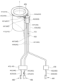
図1は、本発明の第1実施形態による移動装置を概略的に示す図である。 Figure 1 is a schematic diagram of a mobile device according to a first embodiment of the present invention.
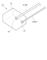
図2は、図1に示された移動装置の一部を示す斜視図である。 Figure 2 is a perspective view showing a portion of the moving device shown in Figure 1.
図3は、図1に示された移動装置の固定部材の斜視図である。 Figure 3 is a perspective view of the fixed member of the moving device shown in Figure 1.
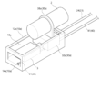
図4および図5は、図1に示された移動装置の第1移動部材を互いに異なる角度から見た斜視図である。 Figures 4 and 5 are perspective views of the first moving member of the moving device shown in Figure 1, viewed from different angles.
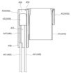
図6および図7は、図1に示された移動装置の作動過程を説明するための図である。 Figures 6 and 7 are diagrams for explaining the operation process of the moving device shown in Figure 1.
図8および図9は、図1に示された固定部材と第1移動部材の変形例を示す図である。 Figures 8 and 9 show modified examples of the fixed member and first movable member shown in Figure 1.
図10~図12は、本発明の第2実施形態による移動装置を概略的に示す図であり、その作動過程を説明するための図である。 Figures 10 to 12 are schematic diagrams showing a moving device according to a second embodiment of the present invention, and are intended to explain its operating process.
図13~図15は、図10に示されたホルダーおよび駆動部の変形例を示す図である。 Figures 13 to 15 show modified examples of the holder and drive unit shown in Figure 10.
図16~図18は、本発明の第3実施形態による移動装置を概略的に示す図であり、その作動過程を説明するための図である。 Figures 16 to 18 are schematic diagrams showing a moving device according to a third embodiment of the present invention, and are intended to explain its operating process.
図19~図22は、図16に示されたホルダーおよび駆動部の変形例を示す図である。 Figures 19 to 22 show modified examples of the holder and drive unit shown in Figure 16.
図23~図26は、本発明の第4実施形態による移動装置を概略的に示す図であり、その作動過程を説明するための図である。 Figures 23 to 26 are schematic diagrams showing a moving device according to a fourth embodiment of the present invention, and are intended to explain its operating process.
図27および図28は、本発明の第5実施形態による移動装置を概略的に示す図である。 Figures 27 and 28 are schematic diagrams illustrating a moving device according to a fifth embodiment of the present invention.
図29は、図27に示された移動装置の分解斜視図である。 Figure 29 is an exploded perspective view of the moving device shown in Figure 27.
図30~図32は、図27に示された移動装置の第1移動部材が固定部材および第2移動部材に対して相対移動する過程を説明するための図である。 Figures 30 to 32 are diagrams for explaining the process by which the first moving member of the moving device shown in Figure 27 moves relative to the fixed member and the second moving member.
図33~図35は、図27に示された移動装置の第1移動部材および第2移動部材が固定部材に対して相対移動する過程を説明するための図である。 Figures 33 to 35 are diagrams for explaining the process by which the first moving member and the second moving member of the moving device shown in Figure 27 move relative to the fixed member.
図36は、図27に示された第1移動部材が作動する方式の一例を説明するための図である。 Figure 36 is a diagram to explain an example of how the first moving member shown in Figure 27 operates.
図37は、図27に示された固定部材、第1移動部材および第2移動部材の断面図である。 Figure 37 is a cross-sectional view of the fixed member, first moving member, and second moving member shown in Figure 27.
以下、添付の図面を参照して本発明の実施形態について本発明の属する技術分野における通常の知識を有する者が容易に実施することができるように詳細に説明する。
本発明は、様々な異なる形態で具現することができ、ここで説明する実施形態に限定されない。
本発明を明確に説明するために図面で説明と関係ない部分を省略し、明細書全体において同一または類似の構成要素に対しては、同じ参照符号を付けた。
DETAILED DESCRIPTION OF THE PREFERRED EMBODIMENTS Hereinafter, preferred embodiments of the present invention will be described in detail with reference to the accompanying drawings so that those skilled in the art can easily carry out the present invention.
As those skilled in the art would realize, the described embodiments may be modified in various different ways, all without departing from the spirit or scope of the present invention.
In order to clearly explain the present invention, parts not related to the description will be omitted in the drawings, and the same reference numerals will be used throughout the specification to refer to the same or similar components.
本明細書および請求範囲に使用された単語と用語は、通常的または辞書的な意味に限定して解釈されず、自分の発明を最善の方法で説明するために発明者が用語と概念を定義できる原則により本発明の技術的思想に符合する意味や概念で解釈すべきである。 The words and terms used in this specification and claims should not be interpreted in a limited manner to their ordinary or dictionary meanings, but should be interpreted in a manner that is consistent with the technical ideas of the present invention, based on the principle that the inventor can define the terms and concepts in order to best describe his or her invention.
本明細書において、「含む」または「有する」などの用語は、明細書上に記載された特徴、数字、段階、動作、構成要素、部品またはこれらを組み合わせたものが存在することを説明しようとするものであり、1つまたはそれ以上の他の特徴や数字、段階、動作、構成要素、部品またはこれらを組み合わせたものの存在または付加可能性をあらかじめ排除しないものと理解すべきである。 In this specification, the terms "comprise" or "have" are intended to describe the presence of features, numbers, steps, operations, components, parts, or combinations thereof described in the specification, and should be understood as not precluding the presence or additional possibility of one or more other features, numbers, steps, operations, components, parts, or combinations thereof.
任意の構成要素が他の構成要素の「前方」、「後方」、「上部」または「下部」にあるというのは、特別な事情がない限り、他の構成要素とすぐに当接して「前方」、「後方」、「上部」または「下部」に配置されるものだけでなく、それらの中間にまた他の構成要素が配置される場合も含む。
また、任意の構成要素が他の構成要素と「連結「されているというのは、特別な事情がない限り、互いに直接連結されることだけでなく、間接的に互いに連結される場合も含む。
When a component is referred to as being "in front,""inrear,""above," or "below" another component, it does not only mean, unless there are special circumstances, that the component is immediately abutted against the other component and is positioned "in front,""inrear,""above," or "below," but also includes cases where other components are positioned between them.
In addition, when any component is "connected" to another component, this includes not only direct connection to each other, but also indirect connection to each other, unless there are special circumstances.
本発明の一実施形態による移動装置は、管形部材の一側に設けられる固定部材と第1移動部材の相対的な移動を発生させるための装置であり、可撓性と所定の引張剛性を有する薄い線形部材であるテンドンと前記テンドンが貫通し且つ可撓性と所定の圧縮剛性を有する管形部材であるシースとの間の相対的な移動を発生させて、前記テンドンまたは前記シースの一側が結合する第1移動部材と固定部材との間の相対的な移動を発生させる移動装置に関する。 The moving device according to one embodiment of the present invention is a device for generating relative movement between a fixed member and a first moving member provided on one side of a tubular member, and relates to a moving device that generates relative movement between a tendon, which is a thin linear member having flexibility and a predetermined tensile stiffness, and a sheath, which is a tubular member through which the tendon passes and has flexibility and a predetermined compressive stiffness, and generates relative movement between the first moving member to which one side of the tendon or the sheath is connected and the fixed member.
この際、管形部材は、長さ方向に延長形成され、一方向に曲がることができる可撓性と柔軟性を有する部材を意味し、固定部材および第1移動部材は、前記管形部材の一側に設置され、所定の機能を行う装置の一部分を意味する。 In this case, the tubular member refers to a member that is elongated in the length direction and has flexibility and can bend in one direction, and the fixed member and the first movable member refer to parts of a device that are installed on one side of the tubular member and perform a specific function.
本実施形態においてテンドンがシースに引き込まれるというのは、テンドンの一端部または一部分がシースの一端部に設けられた開口の内側に入ることを意味し、テンドンがシースから引き出されるというのは、シース内部に収容されたテンドンの一端部または一部分がシースの一端部に設けられた開口から出ることを意味し、駆動部がテンドンまたはシースをリリースするというのは、駆動部がテンドンとシースとの間の相対的な移動が円滑に行われ得るようにテンドンまたはシースの拘束を多少解除することを意味する。 In this embodiment, the tendon being drawn into the sheath means that one end or part of the tendon enters inside an opening provided at one end of the sheath, the tendon being drawn out of the sheath means that one end or part of the tendon contained inside the sheath exits from an opening provided at one end of the sheath, and the driver releasing the tendon or sheath means that the driver releases the tendon or sheath to some extent so that relative movement between the tendon and sheath can be performed smoothly.
例えば、管形部材は、内視鏡からなってもよく、固定部材および第1移動部材は、内視鏡の端部に設けられ、所定の機能、例えば内視鏡を用いた手術や施術を行うためのエンドエフェクターの一部分で構成され得るが、管形部材、固定部材および第1移動部材がこれらに限定されるものではない。 For example, the tubular member may be an endoscope, and the fixed member and the first movable member may be provided at the end of the endoscope and constitute a part of an end effector for performing a specific function, such as surgery or treatment using the endoscope, but the tubular member, fixed member and first movable member are not limited to these.
図1は、本発明の第1実施形態による移動装置を概略的に示す図である。
図2は、図1に示された移動装置の一部を示す斜視図である。
図3は、図1に示された移動装置の固定部材の斜視図である。
図4および図5は、図1に示された移動装置の第1移動部材を互いに異なる角度から見た斜視図である。
FIG. 1 is a schematic diagram of a moving device according to a first embodiment of the present invention.
FIG. 2 is a perspective view showing a portion of the moving device shown in FIG.
3 is a perspective view of a fixed member of the moving device shown in FIG. 1. FIG.
4 and 5 are perspective views of the first moving member of the moving device shown in FIG. 1, as viewed from different angles.
以下、図1~図9を説明するに際して、図1の左側方向を前方と言い、右側方向を後方と規定して説明する。
なお、図2および図3で、固定部材によって透視される構成は、点線で表示された。
In the following description of FIGS. 1 to 9, the left side in FIG. 1 will be defined as the front, and the right side as the rear.
In addition, in Figs. 2 and 3, the configuration seen through the fixing members is shown by dotted lines.
図1を参照すると、本発明の第1実施形態による移動装置1は、固定部材10、第1テンドン20、第2シース23、第1移動部材30、第1シース40、第2テンドン43、第1ホルダー70および第2ホルダー76、第1駆動部80および第2駆動部86を含んでもよい。
Referring to FIG. 1, the moving
図2および図3を参照すると、固定部材10は、直六面体形状を有する胴体12からなってもよく、胴体12の一側および他側、例えば、前方と後方には、それぞれ開口13a、13bが形成されてもよい。
Referring to Figures 2 and 3, the fixing
この際、固定部材10の胴体12の形状は、固定部材10が結合する管形部材の形状に合わせて曲面を含むように屈曲して形成されるなど本発明の技術思想を害しない範囲内で多様に変形または修正されてもよい。
In this case, the shape of the
胴体12の内部には、所定の方向に沿って延長形成され、第1移動部材30が収容されるガイドホール13が形成される。
第1移動部材30は、ガイドホール13内部でガイドホール13の延長方向に沿って固定部材10に対して相対的に移動可能に結合する。
A
The first
この際、本実施形態においてガイドホール13は、胴体12の長さ方向に沿って直線方向に形成されるが、他の実施形態においてガイドホール13の延長方向は、曲線に沿って形成されることもできる。
例えば、第1移動部材30が行う機能または第1移動部材30の一側に設置される所定の部材が行う機能に適合するように、ガイドホール13は、一区間が曲がるように形成されてもよい。
In this embodiment, the
For example, the
また、本実施形態では、第1移動部材30が外部から保護され得るように固定部材10の内部に収容されるが、他の実施形態においてガイドホール13は、固定部材10の外側部に形成されるガイド溝に変形され、第1移動部材30は、固定部材10の外側でガイド溝の延長方向に沿って相対的に移動可能に形成されてもよい。
In addition, in this embodiment, the first moving
固定部材10の一側、例えば、前方の端部には、柔軟な素材からなり、細くて長い形状を有する第1テンドン20が結合する。
このために、固定部材10の前方の端部には、第1テンドン20の一側21が固定される第1テンドン固定部14が形成される。
第1テンドン固定部14は、第1テンドン20が嵌合する結合ホールからなってもよい。
第1テンドン20は、後方に向かって延びるように配置される。
A
For this purpose, a first
The first
The
固定部材10の他側、例えば、後方の端部には、内部にテンドンを収容できる中空形状を有する第2シース23が結合する。
このために、固定部材10の後方の端部には、第2シース23の一側24が結合する第2シース固定部16が形成される。
第2シース固定部16は、第2シース23が嵌合する結合ホールからなってもよい。
A
For this purpose, a second
The second
この際、第1テンドン20および第2シース23が結合することができると、第1テンドン固定部14および第2シース固定部16は、その構造が特に限定されない。
例えば、第1テンドン20は、別途の固定部なしに固定部材10に溶接または接着剤などによって固定されることもできる。
In this case, as long as the
For example, the
図2、図4および図5を参照すると、第1移動部材30は、ガイドホール13に配置される胴体32からなってもよい。
第1移動部材30には、内部にテンドンを収容できる中空形状を有する第1シース40、および柔軟な素材からなり、細くて長い形状を有する第2テンドン43が結合する。
2, 4 and 5, the first moving
The first moving
このために、第1移動部材30には、第1シース40の一側41が結合する第1シース固定部34および第2テンドン43の一側44が結合する第2テンドン固定部35が形成される。
この際、上記で第1テンドン固定部14および第2シース固定部16と関連して説明したように、第1シース固定部34および第2テンドン固定部35は、第1シース40および第2テンドン43が固定され得る場合、その構造が特に限定されるものではない。
For this purpose, the first moving
In this case, as explained above in relation to the first
第1シース40は、固定部材10に結合する第1テンドン20が貫通し且つ後方に向かって延び、第2テンドン43は、固定部材10に結合する第2シース23を貫通して後方に延びる。
The
なお、第1移動部材30がガイドホール13の延長方向に沿って移動するとき、延長方向に垂直な方向に振動したり回転したりしないように、第1移動部材30の長さ方向断面は、ガイドホール13の断面に対応する形状を有することができる。
In addition, when the first moving
この際、第1移動部材30の振動や回転を防止し、第1移動部材30の移動をガイドできるように、第1移動部材30と固定部材10のガイドホール13内壁には、ガイド突起(不図示)およびガイド溝(不図示)が設けられてもよい。
At this time, in order to prevent vibration and rotation of the first moving
なお、第1移動部材30は、第1テンドン20の一側21が結合する第1テンドン固定部14と第2シース23の一側24が結合する第2シース固定部16とのとの間で固定部材10に対して相対的に移動可能に形成されてもよい。
The first
すなわち、第1テンドン固定部14と第2シース固定部16は、第1移動部材30の移動区間を決定する基準になりうる。
これによって、第1テンドン固定部14と第2シース固定部16との間の相対的な位置を調整して、第1移動部材30の移動区間の長さおよび経路を設定することができる。
That is, the first
This makes it possible to adjust the relative position between the first
なお、第1移動部材30が第1テンドン固定部14と第2シース固定部16の間(またはガイドホール13)を外れて固定部材10の外側に逃げないように、固定部材10には、第1移動部材30の相対移動区間を制限できる係止部が設けられてもよい。
例えば、第1移動部材30の長さ方向断面は、開口13a、13bより大きく形成され、開口13a、13bの縁部が前記係止部の機能を行うことができる。
In addition, the fixed
For example, the cross section of the first moving
この際、図2をさらに参照すると、第1テンドン20が後方に引っ張られることにより固定部材10が第1テンドン20と共に後方に移動すると、固定部材10と第1移動部材30のとの間に相対的な移動が発生することができる。
Referring further to FIG. 2, when the
または、第2テンドン43が後方に引っ張られることにより第1移動部材30が第2テンドン43にかかる張力によって後方に移動すると、第1移動部材30と固定部材10のとの間に相対的な移動が発生することができる。
Alternatively, when the
この際、相対的な移動が円滑に発生するために、固定部材10と第1移動部材30との間の相対的な移動方向と固定部材10および第1移動部材30に印加される力の方向(すなわち、テンドンの張力)との間の角度は、できるだけ小さいことが好ましい。
At this time, in order for the relative movement to occur smoothly, it is preferable that the angle between the direction of relative movement between the fixed
このために、第1テンドン20と第2テンドン43は、ガイドホール13の延長方向に沿って互いに平行に配置されてもよい。
また、第2シース23と第1シース40は、後方に向かって延び、かつ互いに平行に配置されてもよい。
For this purpose, the
Alternatively, the
さらに図1を参照すると、第1テンドン20の他側22は、第1駆動部80と結合し、第1駆動部80によって一側、例えば、図1を基準として後方に引っ張られてもよい。
これによって、第1テンドン20の他側22は、第1シース40の他側42から引き出されてもよい。
Still referring to FIG. 1, the
This allows the
第2テンドン43の他側45は、第2駆動部86と結合し、第2駆動部86によって一側、例えば、図1を基準として後方に引っ張られてもよい。
これによって、第2テンドン43の他側45は、第2シース23の他側25から引き出されてもよい。
The
This allows the
この際、第1駆動部80および第2駆動部86は、第1テンドン20および第2テンドン43を引っ張ることができる様々な構成からなってもよい。
例えば、第1駆動部80および第2駆動部86は、アクチュエータまたは手で操作可能な作動部材からなってもよい。
In this case, the
For example,
すなわち、第1駆動部80および第2駆動部86は、それぞれ第1テンドン20および第2テンドン43が巻かれたプリーを回転させるモーターからなってもよい。
または、第1駆動部80および第2駆動部86は、第1テンドン20および第2テンドン43がそれぞれ結合し、リニアアクチュエータによって移動する作動部材からなってもよい。
That is, the
Alternatively, the
第2シース23の他側25は、第2ホルダー76によって固定される。
第2ホルダー76は、第2テンドン43が第2駆動部86によって引っ張られても、第2シース23の他側25が摩擦力によって第2テンドン43と共に後方に移動しないように固定する機能を行う。
これによって、第2シース23と第2テンドン43との間の相対移動が発生することができる。
The
The
This allows relative movement to occur between the
これと同様に、第1シース40の他側42は、第1ホルダー70によって固定される。
第1ホルダー70は、第1テンドン20が第1駆動部80によって引っ張られても、第1シース40の他側42が摩擦力によって第1テンドン20と共に後方に移動しないように固定する機能を行う。
これによって、第1シース40と第1テンドン20との間の相対移動が発生することができる。
Similarly, the
The
This allows relative movement to occur between the
この際、第1ホルダー70および第2ホルダー76は、それぞれ第1シース40および第2シース23が嵌合する固定用フレームからなってもよいが、第1ホルダー70および第2ホルダー76と第1テンドン20および第2テンドン43との間の相対運動を発生させることができると、特に限定されない。
In this case, the
以下、本発明の第1実施形態による移動装置の固定部材と第1移動部材との間に発生する相対的な移動をより詳細に説明する。 The relative movement that occurs between the fixed member and the first moving member of the moving device according to the first embodiment of the present invention will be described in more detail below.
図6および図7は、図1に示された移動装置の作動過程を説明するための図である。 Figures 6 and 7 are diagrams for explaining the operation process of the moving device shown in Figure 1.
図6および図7において固定部材は、内部が見えるように断面が示され、図8および図9で固定部材によって透視される構成は、点線で表示された。 In Figures 6 and 7, the fixing member is shown in cross section so that the inside can be seen, and in Figures 8 and 9, the structure seen through the fixing member is shown by dotted lines.
図6の(a)を参照すると、第1移動部材30は、ガイドホール13の前方の端部側に位置する。
この際、固定部材10に対する第1移動部材30の相対的な位置を第1位置という。
第2駆動部86が第2テンドン43の他側45を後方に引っ張ると、第2テンドン43の他側45は、第2シース23の他側25から引き出され、第2テンドン43の一側44は、第2シース23の一側24に引き込まれ、第2テンドン43と第2シース23との間の相対移動が発生する。
6A, the first moving
At this time, the relative position of the first moving
When the
図6の(b)および図6の(c)を参照すると、第2テンドン43に張力がかかることにより、第1移動部材30に後方に力が印加され、第1移動部材30は、固定部材10に対して相対的に後方に移動する。
Referring to Figures 6(b) and 6(c), tension is applied to the
この際、第1駆動部80は、第1テンドン20の他側22をリリースして、第1テンドン20に所定の自由度を付与する。
これによって、第1テンドン20の他側22が第1シース40内部に多少引き込まれるなど第1テンドン20と第1シース40のとの間に相対的な移動が発生することができ、第1移動部材30は、第1テンドン20や第1シース40によって抵抗を受けることなく、後方に円滑に移動することができる。
At this time, the
This allows relative movement to occur between the
この際、第1移動部材30は、ガイドホール13の後方の端部側に位置するまで固定部材10と相対的に移動することができる。
この際、固定部材10に対する第1移動部材30の相対的な位置を第2位置という。
At this time, the first moving
At this time, the relative position of the first moving
図7の(a)を参照すると、第1移動部材30は、第2位置に位置することができる。
第1駆動部80が第1テンドン20の他側22を後方に引っ張ると、第1テンドン20の他側22は、第1シース40の他側42から引き出され、第1テンドン20の一側21は、第1シース40の一側41に引き込まれ、第1テンドン20と第1シース40との間の相対移動が発生する。
Referring to FIG. 7A, the first moving
When the
図7の(b)および図7の(c)を参照すると、第1テンドン20に張力がかかることにより、固定部材10に後方に力が印加され、固定部材10は、第1移動部材30に対して相対的に後方に移動する。
Referring to Figures 7(b) and 7(c), tension is applied to the
この際、第2駆動部86は、第2テンドン43の他側45をリリースして、第2テンドン43に所定の自由度を付与する。
これによって、第2テンドン43の他側45が第2シース23内部に多少引き込まれるなど第2テンドン43と第2シース23のとの間に相対的な移動が発生することができ、固定部材10が第2テンドン43や第2シース23によって抵抗を受けることなく、後方に円滑に移動することができる。
At this time, the
This allows relative movement to occur between the
なお、前述した相対的な移動を第1移動部材30を基準として説明すると、第1移動部材30は、固定部材10に対して相対的に前方に移動する。
このように、本実施形態によれば、第1移動部材30と固定部材10との間の相対的な線形運動をガイドホール13の延長方向に沿って発生させることができる。
When the above-mentioned relative movement is explained with the first moving
In this manner, according to the present embodiment, the relative linear motion between the first moving
以下、本発明の第1実施形態による移動装置の固定部材と第1移動部材の変形例について説明する。
図8および図9は、図1に示された固定部材と第1移動部材の変形例を示す図である。
Modifications of the fixed member and the first movable member of the moving device according to the first embodiment of the present invention will be described below.
8 and 9 are diagrams showing modified examples of the fixed member and the first moving member shown in FIG.
図8を参照すると、本実施形態の変形例によれば、固定部材10の外側部には、内視鏡装置の先端部2が結合できる内視鏡固定部18が形成されてもよい。
これによって、固定部材10は、内視鏡装置の先端部2に位置固定されてもよい。
Referring to FIG. 8, according to a modification of this embodiment, an
Thereby, the fixing
なお、第1移動部材30の前方側には、内視鏡装置用手術部材3が結合してもよい。
例えば、内視鏡装置用手術部材3は、手術用鉗子または手術用ナイフからなってもよい。
In addition, the
For example, the
この際、固定部材10の前方側開口13bは、内視鏡装置用手術部材3が貫通して通過できるサイズで形成されてもよい。
In this case, the
これによって、第1移動部材30が第2位置に位置した状態で内視鏡装置用手術部材3は、固定部材10のガイドホール13内部に位置し、外部から保護することができる。
また、固定部材10および第1移動部材30が目標位置に到達すると、第1移動部材30が第1位置に位置するように相対移動が発生し、内視鏡装置用手術部材3が固定部材10の外側に突出して所定の機能を行うことができる。
As a result, when the first moving
Furthermore, when the fixed
また、内視鏡装置用手術部材3が固定部材10の内部に収容されているので、固定部材10および第1移動部材30が目標位置に移動する過程で、内視鏡装置用手術部材3によって発生しうる人体内部組織の損傷を防止することができる。
In addition, since the
図9を参照すると、本実施形態のさらに他の変形例によれば、固定部材10aの側部には、ガイドホールと連結される側部開放ホール18aが形成される。
この際、側部開放ホール18aは、第1移動部材30aと固定部材10aとの間の相対的な移動距離に対応して、ガイドホールの延長方向に十分な長さだけ形成されてもよい。
Referring to FIG. 9, according to yet another modification of the present embodiment, a
In this case, the side
第1移動部材30aの胴体32aの側部には、固定部材10aの側部開放ホール18aを貫通して外側に突出する内視鏡固定部38aが形成される。
内視鏡固定部38aには、内視鏡装置の先端部2が結合する。
これによって、第1移動部材30aは、内視鏡装置の先端部2に位置固定されてもよい。
An
The
Thereby, the first moving
第1移動部材30の胴体32aの前方側には、内視鏡装置用手術部材3が結合する。
これによって、内視鏡装置用手術部材3と内視鏡装置の先端部2は、第1移動部材30aと一体に移動することができる。
The
This allows the
これによって、内視鏡装置の先端部2と内視鏡装置用手術部材3は、相互に対して相対的に移動しなくてもよい。
また、第1移動部材30aが第2位置に位置し、内視鏡装置用手術部材3が固定部材10aによって外部から保護することができ、第1移動部材30aが第1位置に位置し、内視鏡装置用手術部材3が固定部材10aの外側に露出してもよい。
This means that the
In addition, the first
以下、本発明の第2実施形態による移動装置について説明する。 The following describes the mobile device according to the second embodiment of the present invention.
図10~図12は、本発明の第2実施形態による移動装置を概略的に示す図であり、その作動過程を説明するための図である。
図13~図15は、図10に示されたホルダーおよび駆動部の変形例を示す図である。
10 to 12 are diagrams illustrating a movement device according to a second embodiment of the present invention, and are diagrams for explaining the operation process thereof.
13 to 15 are diagrams showing modifications of the holder and the drive unit shown in FIG.
以下、図10~図15を説明するに際して、図10の左側方向を前方と規定し、右側方向を後方と規定して説明する。
なお、図10~図13で、固定部材は、内部が見えるように断面が示された。
10 to 15, the left side of FIG. 10 is defined as the front, and the right side of FIG. 10 is defined as the rear.
10 to 13, the fixing member is shown in cross section so that the inside can be seen.
図10を参照すると、本発明の第2実施形態による移動装置101は、固定部材110、第1テンドン120、第2シース123、第1移動部材130、第1シース140、第2テンドン143、第1ホルダー170および第2ホルダー176、第1駆動部180および第2駆動部186を含んでもよい。
Referring to FIG. 10, the moving
この際、第2実施形態による移動装置101において、固定部材110、第1テンドン120、第1移動部材130、第2テンドン143、第1ホルダー170および第2ホルダー176、第1駆動部180および第2駆動部186は、本発明の第1実施形態と同じ構成からなってもよいところ、それに関する詳細な説明を省略する。
In this case, in the moving
すなわち、第1移動部材130は、固定部材110のガイドホール113に相対移動可能に結合し、ガイドホール113に沿って第1位置および第2位置との間を移動することができ、第1移動部材130には、第2テンドン143の一側144が結合し、固定部材110の前方の端部には、第1テンドン120の一側121が結合する第1テンドン固定部114が形成される。
第1テンドン120の他側122は、第1駆動部180によって引っ張られるように第1駆動部180に結合し、第2テンドン143の他側145は、第2駆動部186によって引っ張られるように第2駆動部186に結合する。
第1ホルダー170には、後述する第1シース140の他側142が固定結合して、第1テンドン120が第1駆動部180によって引っ張られると、第1テンドン120の他側122が第1シース140から引き出され、第1テンドン120と第1シース140との間の相対移動が発生する。
第2ホルダー176には、後述する第2シース123の他側125が固定結合して、第2テンドン143が第2駆動部186によって引っ張られると、第2テンドン143の他側145が第2シース123から引き出され、第2テンドン143と第2シース123との間の相対移動が発生する。
That is, the first
The
The
The
以下、第2シース123および第1シース140と本実施形態による移動装置101の作動過程についてより詳細に説明する。
The
図10~図12を参照すると、第1移動部材130には、第1シース140の一側141が結合し、固定部材110の後方の端部には、第2シース123の一側124が結合する。
この際、第1移動部材130が第2位置に位置した状態で、第1シース140は、屈曲して配置されてもよい。
10 to 12, one
At this time, when the first moving
より具体的には、第1シース140は、第1移動部材130が第2位置に位置した状態で外側に屈曲して曲がる屈曲部140aを含んでもよい。
なお、図10では、屈曲部140aが第1シース140の一区間に集中的に形成されるように示されたが、屈曲部140aは、第1シース140の複数の区間に多少小さいサイズをもって分散的に形成されることもできる。
More specifically, the
In addition, although FIG. 10 shows the
図10および図11を参照すると、第1移動部材130が第2位置に位置した状態で第1駆動部180が第1テンドン120の他側122を引っ張ると、第1テンドン120の他側122が第1シース140の他側142から引き出され、第1テンドン120の一側121が第1シース140の一側141に引き込まれ、第1テンドン120と第1シース140との間の相対移動が発生する。
Referring to Figures 10 and 11, when the first moving
第1シース140から第1テンドン120の他側122が引き出されると、第1テンドン120と第1シース140のとの間に相互作用力が発生し、第1テンドン120は、後方に第1シース140を加圧し、この力(圧縮力)は、屈曲部140aに集中的に印加される。
When the
この際、第1シース140に印加された圧縮力および第1ホルダー170の支持力によって、第1シース140の屈曲部140aには、前方に反発力が作用し、屈曲部140aは、反発力によって曲率が減少して広がる。
At this time, a repulsive force acts forward on the
これによって、第1シース140の一側141は、第1移動部材130を前方に押し出し、第1移動部材130は、固定部材110に対して前方に相対的に線形移動する。
As a result, one
なお、第2駆動部186は、第2テンドン143の他側145をリリースして、第2テンドン143に所定の自由度を付与する。
これによって、第2テンドン143の他側145が第2シース123内部に多少引き込まれるなど第2テンドン143と第2シース123のとの間に相対的な移動が発生することができ、第1移動部材130は、第2テンドン143によって抵抗を受けることなく、前方に円滑に移動することができる。
In addition, the
As a result, relative movement can occur between the
図12を参照すると、第1シース140の屈曲部140aが広がるにつれて第1シース140と第2シース123が平行に配置されると、第1移動部材130が第1位置に位置することができる。
この際、第1移動部材130が第1位置に迅速に移動したり完全に移動するためには、第1移動部材130が第1位置に位置した状態でも第1シース140が第1移動部材130に前方に持続的に反発力を印加することができるように構成されることが好ましい。
Referring to FIG. 12, when the
In this case, in order for the first moving
言い換えれば、第1移動部材130が第1位置に位置した状態でも第1シース140が多少屈曲して配置され、第1シース140の屈曲部140aが残存するように構成されることが好ましい。
In other words, it is preferable that the
なお、第2駆動部186が第2テンドン143の他側145を引っ張り、第1駆動部180が第1テンドン120の他側122をリリースすると、第2テンドン143と第2シース123との間の相対移動が発生し、第2テンドン143にかかる張力によって第1移動部材130が固定部材110に対して相対的に後方に移動する。
When the
それと同時に、第1テンドン120の他側122は、第1シース140内部に多少引き込まれ、第1移動部材130が後方に移動するにつれて第1シース140の所定区間には、屈曲部140aがさらに形成される。
At the same time, the
このように、本実施形態によれば、第1シース140に印加された圧縮力および反発力を用いて第1移動部材130と固定部材110との間の相対的な線形移動を発生させることができる。
In this manner, according to this embodiment, relative linear movement between the first
以下、本発明の第2実施形態による移動装置の第1駆動部および第2駆動部の変形例について説明する。 Below, we will explain modified examples of the first drive unit and the second drive unit of the moving device according to the second embodiment of the present invention.
図13を参照すると、本実施形態の変形例による移動装置の第1ホルダー170aおよび第2ホルダー176aと第1駆動部180aおよび第2駆動部186aは、一体に形成されてもよい。
より具体的には、第1ホルダー170aおよび第2ホルダー176aと第1駆動部180aおよび第2駆動部186aは、一側、例えば、図13を基準として上側に位置する第1胴体部182aおよび第1胴体部182aの下側に位置する第2胴体部188aからなってもよい。
13, the first and
More specifically, the
第1胴体部182aの内部には、第1テンドン120の延長方向に形成され、且つ一側が開放された第1ガイド溝183aが形成され、第1ガイド溝183aの内側には、第1作動部材181aが延長方向に移動可能に結合する。
第1作動部材181aには、第1テンドン120の他側122が固定結合する。
第1胴体部182aの前方側には、第1シース140の他側142が固定される第1ホルダー170aが形成される。
A
The
A
第2胴体部188aの内部には、第2テンドン143の延長方向に形成され、且つ一側が開放された第2ガイド溝189aが形成され、第2ガイド溝189aの内側には、第2作動部材187aが延長方向に移動可能に結合する。
第2作動部材187aには、第2テンドン143の他側145が固定結合する。
第2胴体部188aの前方側には、第2シース123の他側125が固定される第2ホルダー部176aが形成される。
A
The
A
これによって、ユーザは、第1作動部材181aおよび第2作動部材187aのうちいずれか1つを後方に移動させ、他のいずれか1つをリリースすることによって、第1移動部材と固定部材の相対的な移動を発生させることができる。
This allows the user to move either the
例えば、第1作動部材181aを後方に移動させて第1テンドン120を後方に引っ張り、第2作動部材187aの拘束を解除して第2テンドン143をリリースすることによって、第1移動部材を固定部材に対して相対的に前方に移動させることができる。
For example, the first movable member can be moved forward relative to the fixed member by moving the
図14を参照すると、本実施形態のさらに他の変形例による移動装置の第1駆動部180aおよび第2駆動部186aは、第1アクチュエータ190aおよび第2アクチュエータ193aをさらに含んでもよい。
この際、第1駆動部180aおよび第2駆動部186aは、第1アクチュエータ190aおよび第2アクチュエータ193a以外の構成は、上記で説明した変形例と同じ構成からなってもよいところ、それに関する説明を省略する。
Referring to FIG. 14, the
In this case, the
第1アクチュエータ190aは、第1作動部材181aに結合する第1結合部材191aおよび第1結合部材191aを前後方に移動させる動力を発生させるための第1動力発生装置192aからなってもよい。
The
第1アクチュエータ190aと同様に、第2アクチュエータ193aは、第2作動部材187aに結合する第2結合部材194aおよび第2結合部材194aを前後方に移動させる動力を発生させるための第2動力発生装置195aからなってもよい。
Similar to the
本変形例によれば、ユーザは、第1アクチュエータ190aおよび第2アクチュエータ193aの作動を制御することによって、第1作動部材181aおよび第2作動部材187aのうちいずれか1つを後方に移動させ、他のいずれか1つをリリースすることができるので、第1移動部材と固定部材の相対的な移動を発生させることができる。
According to this modified example, the user can control the operation of the
図15を参照すると、本実施形態のさらに他の変形例による第1ホルダー170bおよび第2ホルダー176bと第1駆動部180bおよび第2駆動部186bは、一体に形成されてもよい。
より具体的には、第1ホルダー170bおよび第2ホルダー176bと第1駆動部180bおよび第2駆動部186bは、第1テンドン120および第2テンドン143の長さ方向に延長形成される胴体部182bからなってもよい。
15, according to yet another modified example of the present embodiment, a
More specifically, the
胴体部182bの内側には、一側が開放され、且つ延長方向に沿って形成されるガイド溝185bが形成される。
この際、ガイド溝185bは、内部に第1テンドン120および第2テンドン143が平行に通過できるように、第1テンドン120および第2テンドン143の配列方向に十分な幅を有するように形成される。
The
In this case, the
胴体部182bの前方には、第1シース140および第2シース123がそれぞれ結合する第1ホルダー170bおよび第2ホルダー176bが形成される。
A
ガイド溝185bの内壁には、ガイド溝185bの延長方向に形成され、且つ、延長方向に垂直な方向に所定の距離だけ互いに離隔配置される一対の第1ガイド突起183bおよび第2ガイド突起189bが形成される。
A pair of
第1ガイド突起183bには、第1ガイド突起183bに対応する溝が形成された第1作動部材181bが第1ガイド突起183bの延長方向に沿って移動可能に結合する。
A
第2ガイド突起189bには、第2ガイド突起189bに対応するガイド溝が形成された第2作動部材187bが第2ガイド突起189bの延長方向に沿って移動可能に結合する。
第1作動部材181bには、第1テンドン120の他側122が固定結合し、第2作動部材187bには、第2テンドン143の他側145が固定結合する。
A
The
この際、第1作動部材181bには、それぞれガイド溝185bの延長方向と平行な方向にラックギア形状を有する第1ギア部材184bが形成され、第2作動部材187bにも平行な方向にラックギア形状を有する第2ギア部材190bが形成される。
この際、第1ギア部材184bと第2ギア部材190bは、互いに対向するように配置される。
In this case, a
In this case, the
第1作動部材181bと第2作動部材187bとの間には、第1ギア部材184bおよび第2ギア部材190bと同時に外接する第3ギア部材191bが配置される。
第3ギア部材191bの一側には、第3ギア部材191bを一方向に回転させるための外力を印加できる操作部材192bが設けられる。
A
An operating
ユーザが操作部材192bに外力を印加して第3ギア部材191bを一方向に回転させると、第1作動部材181bおよび第2作動部材187bのうちいずれか1つは、後方に移動し、他の1つは、前方に移動し、第1テンドン120および第2テンドン143のうちいずれか1つは、後方に引っ張られ、他のいずれか1つは、前方にリリースされる。
When the user applies an external force to the operating
これによって、本変形例によれば、ユーザは、操作部材192bのみを操作することによって便利に第1移動部材と固定部材との間の相対的な運動を発生させることができる。
As a result, according to this modified example, the user can conveniently generate relative movement between the first movable member and the fixed member by operating only the operating
もちろん、操作部材192bには、アクチュエータから動力を伝達され得る動力伝達部材が設けられ、ユーザは、アクチュエータを制御することによって、第1移動部材と固定部材の相対的な移動を発生させることもできる。
Of course, the operating
以下、本発明の第3実施形態による移動装置について説明する。 The following describes a mobile device according to the third embodiment of the present invention.
図16~図18は、本発明の第3実施形態による移動装置を概略的に示す図であり、その作動過程を説明するための図である。
図19~図22は、図16に示されたホルダーおよび駆動部の変形例を示す図である。
16 to 18 are diagrams illustrating a movement device according to a third embodiment of the present invention, and are diagrams for explaining the operation process thereof.
19 to 22 are diagrams showing modifications of the holder and the drive unit shown in FIG.
以下、図16~図22を説明するに際して、図16の左側方向を前方と規定し、右側方向を後方と規定して説明する。
なお、図16~図18において固定部材は、内部が見えるように断面が示された。
16 to 22, the left side of FIG. 16 is defined as the front, and the right side of FIG. 16 is defined as the rear.
16 to 18, the fixing member is shown in cross section so that the inside can be seen.
図16を参照すると、本発明の第3実施形態による移動装置201は、固定部材210、第1テンドン220、第2シース223、第1移動部材230、第1シース240、第2テンドン243、第1ホルダー270および第2ホルダー276、第1駆動部280および第2駆動部286を含んでもよい。
Referring to FIG. 16, the moving
この際、第3実施形態による移動装置201において、固定部材210、第1テンドン220、第2シース223、第1移動部材230、第1シース240、第2テンドン243、第2ホルダー276および第2駆動部286は、本発明の第1実施形態と同じ構成からなってもよいところ、それに関する詳細な説明を省略する。
In this case, in the moving
すなわち、第1移動部材230は、固定部材210のガイドホール213に相対移動可能に結合し、ガイドホール213に沿って第1位置および第2位置のとの間を移動することができ、第1移動部材230には、第2テンドン243の一側244が結合し、固定部材210の前方の端部には、第1テンドン220の一側221が結合する第1テンドン固定部214が形成される。
第2テンドン243の他側245は、第2駆動部286によって引っ張られるように第2駆動部286に結合する。
第2駆動部286には、後述する第2シース223の他側225が固定結合し、第2テンドン243が第2駆動部286によって引っ張られると、第2テンドン243の他側245が第2シース223から引き出され、第2テンドン243と第2シース223との間の相対移動が発生する。
That is, the first
The
The
以下、第1ホルダー270および第1駆動部280と本実施形態による移動装置201の作動過程についてより詳細に説明する。
The
本実施形態において、第1ホルダー270は、第1テンドン220の他側222を固定し、第1駆動部280は、第1シース240の他側242に隣接するように結合し、第1シース240を移動させるように設けられる。
このために、第1ホルダー270は、相対的に後方に位置し、第1駆動部280は、相対的に前方に位置する。
In this embodiment, the
To this end, the
これによって、第1駆動部280が第1シース240を前方に移動させると、第1ホルダー270によって固定される第1テンドン220の他側222は、第1シース240の他側242から引き出され、第1テンドン220の一側221は、第1シース240の一側241に引き込まれる。
As a result, when the
図16をさらに参照すると、第1移動部材230が第2位置に位置した状態で第1駆動部280が第1シース240を前方に移動させると、第1シース240の一側241が前方に移動する。
Referring further to FIG. 16, when the first moving
この際、第1シース240は、所定の圧縮剛性を有するので、第1シース140は、第1駆動部280によって前方に移動するにつれて第1移動部材230に前方に力を印加することができる。
なお、第2駆動部286は、第2テンドン243をリリースして所定の自由度を付与する。
At this time, since the
In addition, the
図17および図18を参照すると、第1シース240によって前方に力を印加された第1移動部材230は、ガイドホール213に沿って固定部材210に対して相対的に前方に移動する。
この際、第1移動部材230が移動するにつれて所定の自由度を有する第2テンドン243は、他側245が第2シース223内部に引き込まれる。
17 and 18, the first moving
At this time, as the first moving
このように、本実施形態によれば、第1駆動部280が第1移動部材230に固定される第1シース240を直接前方に移動させることによって、第1移動部材230を固定部材210に対して相対的に前方に移動させることができる。
In this manner, according to this embodiment, the
なお、第2駆動部286が第2テンドン243の他側245を後方に引っ張ると、第2テンドン243の他側245が第2シース223の他側225から引き出され、第2テンドン243の一側244が第2シース223の一側224に引き込まれる。
それと同時に、第1駆動部280が第1シース240の他側242をリリースして第1シース240と第1テンドン220との間の相対運動が発生することができるように所定の自由度を付与する。
これによって、第1移動部材230は、固定部材210に対して相対的に後方に移動することができる。
Furthermore, when the
At the same time, the
This allows the first moving
このように、本実施形態による移動装置201によれば、第1駆動部280が第1移動部材230に固定される第1シース240を直接移動させることによって、第1シース240の剛性を用いて第1移動部材230と固定部材210との間の相対的な移動を発生させることができる。
In this way, according to the moving
なお、本実施形態において第1ホルダー270、第2ホルダー276、第1駆動部280、第2駆動部286および第2シース223の長さL1と第1シース240の長さL2の差異は、特に限定されない。
In this embodiment, the difference between the length L1 of the
以下、本発明の第3実施形態の変形例について説明する。 Below, we will explain a variation of the third embodiment of the present invention.
図19を参照すると、本実施形態の変形例による移動装置の第1ホルダー270aおよび第2ホルダー276aと第1駆動部280aおよび第2駆動部286aは、一体に形成されてもよい。
より具体的には、第1ホルダー270aおよび第2ホルダー276aと第1駆動部280aおよび第2駆動部286aは、一側、例えば、図19を基準として上側に位置する第1胴体部282aおよび第1胴体部282aの下側に位置する第2胴体部288aからなってもよい。
19, the first and
More specifically, the
第1胴体部282aの内部には、第1テンドン220の延長方向に形成され、且つ一側が開放された第1ガイド溝283aが形成され、第1ガイド溝283aの内側には、第1作動部材281aが延長方向に移動可能に結合する。
第1作動部材281aには、第1シース240の他側242が固定結合する。
第1胴体部182aの後方側には、第1テンドン220の他側222が固定される第1ホルダー270aが形成される。
A
The
A
第2胴体部288aの内部には、第2テンドン243の延長方向に形成され、且つ一側が開放された第2ガイド溝289aが形成され、第2ガイド溝289aの内側には、第2作動部材287aが延長方向に移動可能に結合する。
第2作動部材287aには、第2テンドン243の他側245が固定結合する。
第2胴体部288aの前方側には、第2シース223の他側225が固定される第2ホルダー276aが形成される。
A
The
A
これによって、ユーザは、第1作動部材281aを前方または後方に移動させ、第2作動部材187aをリリースしたり、第1作動部材281aの移動方向と平行な方向に移動させることによって、第1移動部材と固定部材の相対的な移動を発生させることができる。
This allows the user to move the
例えば、第1作動部材281aを前方に移動させて第1シース240を前方に移動させ、第2作動部材287aの拘束を解除して第2テンドン143をリリースさせたり、第2作動部材287aを前方に移動させることによって、第1移動部材を固定部材に対して相対的に前方に移動させることができる。
For example, the
図20を参照すると、本実施形態のさらに他の変形例において、第1ホルダー270aおよび第2ホルダー276a、第1駆動部280aおよび第2駆動部286aと前述した第1作動部材および第2作動部材は、一体に形成されてもよい。
Referring to FIG. 20, in yet another variation of this embodiment, the
より具体的には、第1ホルダー270bおよび第2ホルダー276bと第1駆動部280bおよび第2駆動部286bは、第1テンドン220および第2テンドン243の長さ方向に延長形成される胴体部282bからなってもよい。
More specifically, the
胴体部282bの内側には、一側が開放され、且つ延長方向に沿って形成されるガイド溝283bが形成される。
この際、ガイド溝283bは、内部に第1テンドン220および第2テンドン243が平行に通過できるように、第1テンドン220および第2テンドン243の配列方向に十分な幅を有するように形成される。
The
In this case, the
胴体部282bの後方側には、第1テンドン220の他側222が固定結合する第1ホルダー270bが形成され、胴体部282bの前方側には、第2シース223の他側225が固定結合する第2ホルダー276bが形成される。
A
ガイド溝283bの内側には、ガイド溝283bの延長方向に沿って移動可能に作動部材281bが結合する。
この際、作動部材281bには、第1シース240の他側242と第2テンドン243の他側245が固定結合する。
An operating
At this time, the
これによって、本変形例によれば、ユーザは、1つの作動部材281bのみを操作することによって、容易に第1移動部材と固定部材との間の相対的な移動を発生させることができる。
例えば、ユーザは、作動部材281bを前方に移動させると、第1シース240は、第1移動部材を前方に押し出して移動させ、第2テンドン243は、前方にリリースされる。
As a result, according to this modified example, the user can easily cause relative movement between the first moving member and the fixed member by operating only one actuating
For example, when the user moves the actuating
図21を参照すると、本実施形態のさらに他の変形例において、第1および第2駆動部280c、286cは、第1アクチュエータ284c、285cおよび第2アクチュエータ290c、291cをさらに含んでもよい。
Referring to FIG. 21, in yet another variation of this embodiment, the first and
この際、本変形例の第1作動部材281cおよび第2作動部材287c、第1胴体部282cおよび第2胴体部288c、第1ガイド溝283cおよび第2ガイド溝289c、第1ホルダー270cおよび第2ホルダー276cは、上記で図19とともに説明した変形例の第1作動部材281aおよび第2作動部材287a(図19参照)、第1胴体部282aおよび第2胴体部288a(図19参照)、第1ガイド溝283aおよび第2ガイド溝289a(図19参照)と同じ構成からなってもよいところ、それに関する説明を省略する。
In this case, the first and
本変形例において、第1アクチュエータ284c、285cは、第1作動部材281cに結合する第1結合部材284cを前後方に移動させる動力を発生させるための第1動力発生装置285cからなってもよい。
In this modified example, the
第1アクチュエータ284c、285cと同様に、第2アクチュエータ290c、291cは、第2作動部材287cに結合する第2結合部材290cを前後方に移動させる動力を発生させるための第2動力発生装置291cからなってもよい。
Similar to the
本変形例によれば、ユーザは、第1アクチュエータ284c、285cおよび第2アクチュエータ290c、291cの作動を制御することによって、第1作動部材281cを移動させ、第2作動部材187aをリリースしたり、第1作動部材281cと平行な方向に移動させることができるので、第1移動部材と固定部材の相対的な移動を発生させることができる。
According to this modified example, the user can control the operation of the
図22を参照すると、本実施形態のさらに他の変形例において、第1ホルダー270dおよび第2ホルダー276dと第1駆動部280dおよび第2駆動部286dは、一体に形成されてもよい。
この際、本変形例の第1アクチュエータ284c、285cおよび第2アクチュエータ290d、291dは、上記で図21と共に説明した変形例の第1アクチュエータ284c、285cおよび第2アクチュエータ290c、291c(図21参照)と同じ構成からなってもよいところ、それに関する説明を省略する。
Referring to FIG. 22, in yet another modification of this embodiment, the
In this case, the
本変形例において、第1駆動部280dは、第1テンドン220の長さ方向に沿って形成される第1胴体部282dからなる。
第1胴体部282dの一側、図22を基準として上側には、第1テンドン220の延長方向に形成される第1ガイド経路283dが位置する。
In this modified example, the
A
第1胴体部282dの上側部には、第1作動部材281dが第1ガイド経路283dに沿って移動可能に結合する。
このために、第1胴体部282dと第1作動部材281dには、それぞれ第1ガイド経路283d方向にガイド突起とガイド溝が形成されてもよい。
第1作動部材281dには、第1シース240の他側242が固定結合する。
A
To this end, the
The
なお、第2駆動部286dは、第2テンドン243の長さ方向に沿って形成される第2胴体部288dからなる。
第2胴体部288dの一側、図22を基準として上側には、第2テンドン243の延長方向に形成される第2ガイド経路289dが位置する。
In addition, the
A
第2胴体部288dの上側部には、第2作動部材287dが第2ガイド経路289dに沿って移動可能に結合する。
このために、第2胴体部288dと第2作動部材287dには、それぞれ第2ガイド経路289d方向にガイド突起とガイド溝が形成されてもよい。
第2作動部材287dには、第2テンドン243の他側245が固定結合する。
A
To this end, the
The
第1胴体部282dの後方側には、第1テンドン220の他側222が固定結合する第1ホルダー270dが形成され、第2胴体部288dの前方側には、第2シース223の他側225が固定結合する第2ホルダー276dが形成される。
A
本変形例によれば、ユーザは、第1アクチュエータ284d、285dおよび第2アクチュエータ290d、291dの作動を制御することによって、第1作動部材281dを移動させ、第2作動部材187dをリリースしたり、第1作動部材281dと平行な方向に移動させることができるので、第1移動部材と固定部材の相対的な移動を発生させることができる。
According to this modified example, the user can control the operation of the
以下、本発明の第4実施形態による移動装置を説明する。 The following describes a mobile device according to the fourth embodiment of the present invention.
図23~図26は、本発明の第4実施形態による移動装置を概略的に示す図であり、その作動過程を説明するための図である。 Figures 23 to 26 are schematic diagrams showing a moving device according to a fourth embodiment of the present invention, and are intended to explain its operating process.
以下、図23~図26を説明するに際して、図23の上側方向を前方と規定し、下側方向を後方と規定し、図24を基準として時計回りおよび反時計回りを規定して説明する。
なお、図24および図26において、固定部材、第1移動部材、第1および第2テンドン第1および第2シース以外の構成を省略された。
23 to 26, the upper direction in FIG. 23 is defined as the front, the lower direction as the rear, and clockwise and counterclockwise directions are defined based on FIG. 24.
In addition, in Figures 24 and 26, components other than the fixed member, the first moving member, the first and second tendons, and the first and second sheaths are omitted.
図23を参照すると、本発明の第3実施形態による移動装置301は、固定部材310、第1テンドン320および第2テンドン323、第1移動部材330、第1シース340および第2シース343、第1ホルダー370および第2ホルダー376、第1駆動部380および第2駆動部386を含んでもよい。
Referring to FIG. 23, the moving
本実施形態において固定部材310の胴体部312は、中心に結合ホール313が形成された円筒形状の部材からなってもよい。
結合ホール313には、管形部材の一部分、例えば内視鏡装置の先端部(不図示)が固定結合することができる。
In this embodiment, the
A portion of a tubular member, for example the tip end of an endoscope device (not shown), can be fixedly coupled to the
固定部材310の外周面には、外側方向に突出し、後述する第1テンドン320の一側321と第2テンドン323の一側324が固定結合するテンドン固定部314が形成される。
The outer peripheral surface of the fixing
固定部材310の外側部には、第1移動部材330の胴体部332が互いに相対的に回転可能に結合する。
この際、第1移動部材330の胴体部332は、円筒形状の部材からなり、固定部材310と中心軸Cを中心に同軸配列されてもよい。
A
In this case, the
第1移動部材330の胴体部332の一側部、例えば、図23を基準として下側部には、外側方向に突出して後述する第1シース340の一側341と第2シース343の一側344が結合するシース固定部334が形成される。
A
なお、第1移動部材330の胴体部332には、固定部材310のテンドン固定部314が貫通するテンドン固定部ガイドホール335が形成される。
この際、テンドン固定部ガイドホール335は、胴体部332の周り方向に沿って形成される。
In addition, a tendon fixing
At this time, the tendon fixing
これによって、第1移動部材330と固定部材310が中心軸Cを中心に相対回転しても、テンドン固定部314がテンドン固定部ガイドホール335に沿ってガイドされるので、第1移動部材330は、テンドン固定部314によって干渉されることなく、相対回転することができる。
As a result, even if the first moving
この際、テンドン固定部ガイドホール335は、一端部が後述する第1シース340の第1部分341aが配置される第1シースガイドホール336と連結される。
第1シース340が配置され得るように、第1シースガイドホール336の一端部、例えば、図23を基準として下端部は、シース固定部334と隣接して位置する。
At this time, one end of the tendon fixing
One end of the first
この際、第1シースガイドホール336は、所定の曲率をもって曲がる経路に沿って形成されてもよい。
より具体的には、第1シースガイドホール336とテンドン固定部ガイドホール335が連結される部分は、胴体部332の周り方向に沿って形成され、第1シースガイドホール336の下端部は、胴体部332の長さ方向に沿って形成され、その間に位置する部分は、所定の曲率をもって曲がるように形成されてもよい。
In this case, the first
More specifically, the portion where the first
テンドン固定部ガイドホール335の他端部は、後述する第2シース343の第1部分344aが配置される第2シースガイドホール337と連結される。
第2シース343が配置され得るように、第2シースガイドホール337の一端部、例えば、図23を基準として下端部は、シース固定部334と隣接して位置する。
The other end of the tendon fixing
One end of the second
この際、第2シースガイドホール337は、所定の曲率をもって曲がる経路に沿って形成されてもよい。
本実施形態において、第2シースガイドホール337とテンドン固定部ガイドホール335が連結される部分は、胴体部332の周り方向に沿って形成され、第2シースガイドホール337の下端部は、胴体部332の長さ方向に沿って形成され、その間に位置する部分は、所定の曲率をもって曲がるように形成されてもよい。
In this case, the second
In this embodiment, the portion where the second
シース固定部334には、第1シース340および第2シース343の一側341、344が固定結合する。
本実施形態において、第1シース340の一側341は、第1シースガイドホール336内側に配置され、所定の曲率をもって曲がる第1部分341aおよび第1部分341aの一端部から第1移動部材330の長さ方向に延長形成される第2部分341bを含んでもよい。
第2シース343の一側344は、第2シースガイドホール337内側に配置され、所定の曲率をもって曲がる第1部分344aおよび第1部分344aの一端部から第1移動部材330の長さ方向に延長形成される第2部分344bを含んでもよい。
To the
In this embodiment, one
One
これによって、第1シース340の一側341および第2シース343の一側344は、内部を貫通する第1テンドン320および第2テンドン323が曲がるにつれて発生しうる摩擦力と抵抗力を最小化し、第1テンドン320および第2テンドン323を第1移動部材330の周り方向にガイドすることができる。
As a result, one
なお、第1シース340の他側342および第2シース343の他側345は、それぞれ第1ホルダー370および第2ホルダー376に固定結合する。
この際、第1ホルダー370および第2ホルダー376は、一体に形成されてもよい。
The
In this case, the first holder 370 and the second holder 376 may be integrally formed.
第1テンドン320は、少なくとも一部が第1シース340の内部に配置されるように第1シース340を貫通する。
第1テンドン320の一側321は、固定部材310のテンドン固定部314に結合する。
The
One
本実施形態において、第1テンドン320の一側321は、一端がテンドン固定部314に固定結合し、第1移動部材330の周り方向に沿って延びる第1部分321aおよび第1部分321aから延び、かつ第1シース340の第1部分341a内側に配置され、所定の曲率をもって曲がる第2部分を含んでもよい。
第1テンドン320の他側322は、第1駆動部380によって引っ張られたりリリースされ得るように第1駆動部380に結合する。
In this embodiment, one
The
なお、第2テンドン323の一側324は、一端がテンドン固定部314に固定結合し、第1移動部材330の周り方向に沿って延びる第1部分324aおよび第1部分324aから延び、かつ第2シース343の第1部分344a内側に配置され、所定の曲率をもって曲がる第2部分を含んでもよい。
第2テンドン323の他側325は、第2駆動部386によって引っ張られたりリリースされ得るように第2駆動部386に結合する。
In addition, one
The
以下、本発明の第4実施形態による移動装置の第1移動部材と固定部材が第1および第2駆動部によって相対的な回転を行う過程を説明する。 The following describes the process by which the first moving member and the fixed member of the moving device according to the fourth embodiment of the present invention are rotated relative to each other by the first and second driving units.
図23~図26を参照すると、第1駆動部380が第1テンドン320の他側322を引っ張ると、第1テンドン320に張力が印加され、第1テンドン320の他側322は、第1シース340の他側342から引き出され、第1テンドン320の一側321は、第1シース340の一側341に引き込まれる相対移動が発生する。
第1テンドン320の他側322が引っ張られることにより、第1テンドン320の一側321は、テンドン固定部314を反時計回りに引っ張る。
23 to 26, when the
As the
これと同時に、第1シース340は、第1テンドン320との相対移動によって第1テンドン320のとの間で相互作用力が発生する。また、所定の圧縮剛性を有する第1シース340は、他側342が第1ホルダー370によって支持されるので、反発力が発生する。
At the same time, an interaction force is generated between the
発生した反発力は、第1シース340の一側341に固定されたシース固定部334を介して第1移動部材330に力を印加する。
この際、第1テンドン320の一側321が周り方向に沿って曲がって配置され、第1シース340の一側341も、端部が周り方向と平行な方向に向かうように曲がって配置されるので、発生した反発力は、第1移動部材330を固定部材310に対して時計回りに相対回転させる。
The generated repulsive force is applied to the first moving
At this time, one
これによって、本実施形態による移動装置301は、第1駆動部380が第1テンドン320の他側322を引っ張ることによって、第1移動部材330を固定部材310に対して時計回りに相対回転させることができる。
As a result, in the moving
それと同時に、第2シース343と第2テンドン323との間の相対移動が外力によって円滑に発生し、第2テンドン323の他側325が第2シース343の他側345に多少引き込まれるように、第2駆動部386は、第2テンドン323の他側325をリリースする。
At the same time, the
これによって、第2テンドン323および第2シース343による抵抗力を最小化することができるので、第1移動部材330が第1テンドン320および第1シース340との間の相対移動によって固定部材310に対して容易に回転することができる。
This minimizes the resistance force from the
なお、第2駆動部386が第2テンドン323の他側325を引っ張り、第1駆動部380が第1テンドン320の他側322をリリースすると、前述した作動過程と類似の作動過程によって、第1移動部材330が固定部材310に対して反時計回りに相対回転することができる。
When the
このように、本実施形態による移動装置301は、第1駆動部380および第2駆動部386のうちいずれか1つが第1テンドン320および第2テンドン323のうちいずれか1つを引っ張り、第1駆動部380および第2駆動部386のうち他のいずれか1つが第1テンドン320および第2テンドン323のうち他のいずれか1つをリリースすることによって、第1移動部材330を固定部材310に対して時計回りにまたは反時計回りに相対回転させることができる。
In this way, the moving
以下、本発明の第5実施形態による移動装置を説明する。 The following describes a mobile device according to the fifth embodiment of the present invention.
図27および図28は、本発明の第5実施形態による移動装置を概略的に示す図である。
図29は、図27に示された移動装置の分解斜視図である。
以下、図27~図37を説明するに際して、図27の上側方向を前方と規定し、下側方向を後方と規定し、上側から見たときを基準として時計回りと反時計回りを規定して説明する。
なお、図28、図30~図36において、第2移動部材は、点線で表示され、第2移動部材によって透視される構成は、実線で表示された。
27 and 28 are diagrams that show a schematic view of a moving device according to a fifth embodiment of the present invention.
29 is an exploded perspective view of the movement device shown in FIG. 27. FIG.
27 to 37, the upper direction in FIG. 27 is defined as the front, the lower direction as the rear, and clockwise and counterclockwise directions are defined based on a view from above.
In addition, in FIG. 28 and FIG. 30 to FIG. 36, the second moving member is shown by a dotted line, and the configuration seen through the second moving member is shown by a solid line.
図27~図29を参照すると、本発明の第5実施形態による移動装置401は、固定部材410、第1テンドン420および第2テンドン423、第1移動部材430、第1シース440および第2シース443、第3テンドン446、第2移動部材450および第3シース460を含んでもよい。
Referring to Figures 27 to 29, the moving
固定部材410は、中心に結合ホール413が形成される円筒形状の部材である胴体部412からなってもよい。
胴体部412の結合ホール413には、管形部材、例えば内視鏡装置の先端部2が固定結合することができる。
固定部材410の外周面には、外側に突出形成され、第1テンドン420および第2テンドン423の一側421、424が固定結合する第1および第2テンドン固定部414が形成される。
The fixing
A tubular member, for example, the
The fixing
より具体的には、第1テンドン420の一側421は、一端が第1および第2テンドン固定部414の一側に結合し、固定部材410の周り方向に延長形成される第1部分421aおよび第1部分421aから固定部材410の胴体部412の長さ方向に延長形成される第2部分421bを含んでもよい。
More specifically, one
この際、第1テンドン420の第1部分421aと第2部分421bが連結される部分は、所定の曲率をもって屈曲して配置される。
これによって、後述する第1駆動部280によって第1テンドン420が引っ張られることにより作用する張力が固定部材410の周り方向に印加される力に円滑に転換することができる。
At this time, the portion where the
As a result, the tension acting when the
これと同様に、第2テンドン423の一側424は、一端が第1および第2テンドン固定部414の一側に結合し、固定部材410の周り方向に延長形成される第1部分424aおよび第1部分424aから固定部材410の胴体部412の長さ方向に延長形成される第2部分424bを含んでもよい。
Similarly, one
この際、第2テンドン423の第1部分424aと第2部分424bが連結される部分は、所定の曲率をもって屈曲して配置される。
これによって、後述する第2駆動部286によって第2テンドン423が引っ張られることにより作用する張力が固定部材410の周り方向に印加される力に円滑に転換することができる。
At this time, the portion where the
As a result, the tension acting when the
第2移動部材450は、円筒形状で形成され、且つ中央部に結合ホール453が形成される胴体部452および胴体部452の外側部に形成される収容部454からなってもよい。
収容部454は、胴体部452の長さ方向(または前後方)に沿って延長形成されてもよい。
収容部454には、後述する第1移動部材430が相対的に移動可能に結合する第1ガイドホール455が形成される。
The second moving
The receiving
The receiving
固定部材410の胴体部412と第2移動部材450の胴体部452は、中心軸Cを中心に同軸配列されてもよい。
この際、第2移動部材450の胴体部452の結合ホール453には、固定部材410が中心軸Cを中心に相対回転が可能であるが、中心軸C方向には相対移動が不可能に結合する。
The
At this time, the fixing
なお、収容部454の第1ガイドホール455は、胴体部452の長さ方向に沿って延長形成される。
この際、第1ガイドホール455の一端部、例えば、図27を基準として後端部には、後述する第3シース460の一側461が固定結合する第3シース固定部458が形成される。
第3シース固定部458は、第3シース460が嵌合する固定ホールからなってもよいが、これに限定されるものではなく、第3シース460の相対移動が制限されるように固定され得る様々な構成からなってもよい。
The
At this time, a third
The third
第1ガイドホール455の他端部、例えば、図27を基準として前端部は、前方に行くほど長さ方向に垂直な断面の面積が増加し、固定部材410の外周部を周り方向に取り囲む第2ガイドホール456が形成されてもよい。
The other end of the
この際、第1ガイドホール455と第2ガイドホール456が連結される部分は、周り方向の一側面と他の側面が互いに遠ざかる方向に傾斜し、且つ多少丸く形成されてもよい。
In this case, the portion where the
固定部材410の外周部を取り囲む第2ガイドホール456の内側には、第1テンドン420の第1部分421a、第2テンドン423の第1部分424a、第1テンドン固定部および第2テンドン固定部414が配置される。
第1ガイドホール455と第2ガイドホール456が連結される部分には、第1テンドン420の第2部分421bと第2テンドン423の第2部分424bが配置される。
The
The
このように、第1テンドン420の一側421および第2テンドン423の一側424は、第1ガイドホール455および第2ガイドホール456によってカイドされることにより、滑らかに屈曲した形状を維持しながら配置されてもよい。
In this manner, one
第1ガイドホール455および第2ガイドホール456には、第1移動部材430が収容部454の延長方向に相対的に移動可能に結合する。しかしながら、第1移動部材430は、第2移動部材450に対して中心軸Cを中心に相対回転が制限されるように結合する。
The first moving
第1移動部材430は、所定長さを有する胴体部432からなってもよい。
第1移動部材の一側部には、第1シース440の一側441が結合する第1シース固定部434および第2シース443の一側444が結合する第2シース固定部435が形成される。
第1移動部材430の一側部には、内視鏡装置用手術部材3が設けられてもよい。
The first moving
A first
A
より具体的には、第1シース固定部434の一側、図27を基準として上側には、所定の自由度をもって曲がる第1シース440の第1部分441aが位置する。
第1シース固定部434には、第1部分441aから延びる第2部分441bが結合する。第1シース440の第1部分441aは、第1シース固定部434によって拘束されずに所定の可変性を有するので、第1移動部材430の外側方向に曲がることができる。
More specifically, a
A
これと同様に、第2シース固定部435の一側、図27を基準として上側には、所定の自由度をもって曲がることができる第2シース443の第1部分444aが位置する。
第2シース固定部435には、第1部分444aから延びる第2部分444bが結合する。
第2シース443の第1部分444aは、第2シース固定部435によって拘束されずに所定の可変性を有するので、第1移動部材430の外側方向に曲がることができる。
Similarly, a
A
The
第1シース440の第1部分441aおよび第2シース443の444aが行う機能に対しては、第1移動部材430と第2移動部材450の相対移動と関連して後述する。
The functions performed by the
第1移動部材430の他側部、例えば、図27を基準として後方部には、第3テンドン446の一側447が固定結合する。
第3テンドン446の少なくとも一部は、第3シース460を貫通し、第3テンドン446の一側447は、第3シース460の一側461から引き出されてもよい。
One
At least a portion of the
第1テンドン420の少なくとも一部は、第1シース440を貫通し、第1テンドン420の一側421は、第1シース440の一側441から引き出されてもよい。
第2テンドン423の少なくとも一部は、第2シース443を貫通し、第2テンドン423の一側424は、第2シース443の一側444から引き出されてもよい。
At least a portion of the
At least a portion of the
すなわち、第1移動部材430の前方には、第1テンドン420の一側421および第2テンドン423の一側424が固定結合する第1テンドン固定部および第2テンドン固定部414が位置し、第1移動部材430の後方には、第3シース460の一側461が固定結合する第3シース固定部458が位置する。
That is, in front of the first moving
なお、第1シース440の他側442、第2シース443の他側445、および第3シース460の他側448は、それぞれ第1、第2および第3ホルダー470、476、478に固定結合し、第1テンドン420の他側422、第2テンドン423の他側425、および第3テンドン446の他側448は、それぞれ第1駆動部480、第2駆動部486および第3駆動部488に結合する。
The
第1駆動部480、第2駆動部486および第3駆動部488が第1テンドン420の他側422、第2テンドン423の他側425、および第3テンドン446の他側448を引っ張ると、第1シース440の他側442、第2シース443の他側445、および第3シース460の他側448は、それぞれ第1、第2および第3ホルダー470、476、478によって固定されているので、第1テンドン420の他側422、第2テンドン423の他側425、および第3テンドン446の他側448が第1シース440の他側442、第2シース443の他側445、および第3シース460の他側448から引き出され、第1テンドン420、第2テンドン423、および第3テンドン446と第1シース440、第2シース443、および第3シース460との間に相対移動が発生することができる。
When the
以下、本発明の第5実施形態による移動装置の固定部材、第1移動部材および第2移動部材が第1~第3ホルダーおよび第1~第3駆動部によって相対的に移動する過程を説明する。 The following describes the process in which the fixed member, the first moving member, and the second moving member of the moving device according to the fifth embodiment of the present invention are moved relatively by the first to third holders and the first to third driving units.
図30~図32は、図27に示された移動装置の第1移動部材が固定部材および第2移動部材に対して相対移動する過程を説明するための図である。
図33~図35は、図27に示された移動装置の第1移動部材および第2移動部材が固定部材に対して相対移動する過程を説明するための図である。
図36は、図27に示された第1移動部材が作動する方式の一例を説明するための図である。
図37は、図27に示された固定部材、第1移動部材および第2移動部材の断面図である。
30 to 32 are diagrams for explaining the process in which the first moving member of the moving device shown in FIG. 27 moves relatively to the fixed member and the second moving member.
33 to 35 are diagrams for explaining the process in which the first moving member and the second moving member of the moving device shown in FIG. 27 move relatively to the fixed member.
FIG. 36 is a diagram for explaining an example of a method for operating the first moving member shown in FIG.
37 is a cross-sectional view of the fixed member, the first moving member, and the second moving member shown in FIG. 27. FIG.
図30~図32を参照すると、本実施形態において第1移動部材430は、固定部材410および第2移動部材450に対して前後方に相対移動することができる。
この際、第1移動部材430の相対移動は、第1テンドン420および第2テンドン423と第1シース440および第2シース443との間の相対的な移動と第3テンドン446と第3シース460との間の相対的な移動によって発生する。
30 to 32, in this embodiment, the first moving
At this time, the relative movement of the first moving
本発明の一実施形態による第1移動部材430の線形的な相対移動は、上記で説明した第1~第3実施形態による移動装置1、101、201(図1、図10、図16参照)のうちいずれか1つと同じ過程からなってもよい。
The linear relative movement of the first
より具体的には、本実施形態において第1移動部材430の線形的な相対移動は、第2実施形態による移動装置101(図10参照)と同じ過程からなってもよい。
すなわち、固定部材410および第2移動部材450は、第2実施形態の固定部材110(図10参照)と同じ機能を行い、第1移動部材430は、第2実施形態の第1移動部材130(図10参照)と同じ機能を行い、第1および第2テンドン420、423は、第2実施形態の第1テンドン120(図10参照)と同じ機能を行い、第1および第2シース440、443は、第2実施形態の第1シース140(図10参照)と同じ機能を行い、第3テンドン446は、第2実施形態の第2テンドン143(図10参照)と同じ機能を行い、第3シース460は、第2実施形態の第2シース123(図10参照)と同じ機能を行い、第1および第2ホルダー470、476は、第2実施形態の第1ホルダー170(図10参照)と同じ機能を行い、第3ホルダー478は、第2実施形態の第2ホルダー176(図10参照)と同じ機能を行い、第1および第2駆動部480、486は、第2実施形態の第1駆動部180(図10参照)と同じ機能を行い、第3駆動部488は、第2実施形態の第2駆動部186(図10参照)と同じ機能を行うように構成されてもよい。
More specifically, in this embodiment, the linear relative movement of the first moving
That is, the fixed
図30を参照すると、第1および第2駆動部480、486がそれぞれ第1および第2テンドン420、423の他側422、425を引っ張ると、第1および第2ホルダー470、476に固定結合した第1および第2シース440、443の他側442、445から第1および第2テンドン420、423の他側422、425が引き出され、第1および第2テンドン420、423と第1および第2シース440、443のとの間に相対的な移動が発生する。
Referring to FIG. 30, when the first and
なお、第3駆動部488は、第3テンドン446の他側448をリリースし、第3テンドン446と第3シース460との間に相対的な移動が起こり得るように所定の自由度を付与する。
The
この際、第1移動部材430が第1ガイドホール455の後方部に位置する場合には、第1および第2シース440、443の第1部分441a、444aは、第1ガイドホール455の延長方向または固定部材410の長さ方向と平行に配置される。
以下、第1移動部材430の前記位置を第2位置という。
In this case, when the first
Hereinafter, this position of the first moving
図31を参照すると、第1および第2テンドン420、423の他側421、424が第1および第2駆動部480、486によって後方に引っ張られると、上記で第2実施形態において説明したように、第1および第2シース440、443は、所定の圧縮剛性をもって第1および第2ホルダー470、476によって支持されるので、第1移動部材430を前方に押し出す反発力を発生させる。
Referring to FIG. 31, when the
このように、本実施形態によれば、第1移動部材430は、第1および第2テンドン420、423と第1および第2シース440、443の相対的な移動によって固定部材410および第2移動部材450に対して前方に線形的な相対移動を行うことができる。
In this manner, according to this embodiment, the first
この際、第3駆動部488は、第3テンドン446の他側448をリリースするので、第3テンドン446の他側448は、第3シース460の内側に引き込まれる。
これによって、第1移動部材430は、第3テンドン446による抵抗力を少なく受けながら前方に移動することができる。
At this time, the
This allows the first moving
図32を参照すると、第1移動部材430が第1ガイドホール455の前方側に到達すると、第1移動部材430が第2移動部材450の収容部454外側に逃げないように、第1移動部材430と第2移動部材450との間の相対的な移動が制限される。
前記作用は、第2移動部材450に設けられる係止部によって行われ得る。
係止部は、図37と共に後述する。
Referring to FIG. 32, when the first
This function can be achieved by a locking portion provided on the second moving
The locking portion will be described later in conjunction with FIG.
なお、第1移動部材430が第1ガイドホール455の前方に移動するにつれて、第1シース440の第1部分441aおよび第2シース443の第1部分444aが第2ガイドホール456の内側に進入すると、第1シース440の第1部分441aおよび第2シース443の第1部分444aは、第1移動部材430の外側に屈曲して曲がる。
As the first moving
この際、第1部分441a、444aは、それぞれ第2ガイドホール456の周り方向の両側部に位置する内側面に沿って所定の曲率をもって曲がるように配置されてもよい。
これによって、第1シース440の第1部分441aおよび第2シース443の第1部分444aは、第1テンドン420および第2テンドン423の間で発生する摩擦力と抵抗力を最小化し、固定部材410の周り方向に延びる第1テンドン420および第2テンドン423をガイドすることができる。
In this case, the
As a result, the
図33~図35を参照すると、本実施形態において第1移動部材430および第2移動部材450は、固定部材410に対して中心軸Cを中心に時計回りまたは反時計回りに相対回転することができる。
この際、第1移動部材430および第2移動部材450の相対回転は、第1テンドン420と第1シース440との間の相対的な移動と第2テンドン423と第2シース443との間の相対的な移動によって発生する。
33 to 35, in this embodiment, the first moving
At this time, the relative rotation of the first moving
本実施形態において、第1移動部材430および第2移動部材450の相対回転は、上記で説明した第4実施形態による移動装置301(図23参照)と同じ過程からなってもよい。
In this embodiment, the relative rotation of the first moving
より具体的には、固定部材410は、第4実施形態の固定部材310(図23参照)と同じ機能を行い、第1移動部材430および第2移動部材450は、第4実施形態の第1移動部材430(図23参照)と同じ機能を行い、第2ガイドホール456は、第4実施形態のテンドン固定部ガイドホール335(図23参照)と同じ機能を行い、第1テンドン固定部および第2テンドン固定部414は、第4実施形態のテンドン固定部314と同じ機能を行い、第1テンドン420および第2テンドン423は、第4実施形態の第1テンドン320および第2テンドン323(図23参照)と同じ機能を行い、第1シース440および第2シース443は、第4実施形態の第1シース340および第2シース343(図23参照)と同じ機能を行い、第1ホルダー470および第2ホルダー476は、第4実施形態の第1ホルダー370および第2ホルダー376と同じ機能を行い、第1駆動部480および第2駆動部486は、第4実施形態の第1駆動部380および第2駆動部386と同じ機能を行うように構成されてもよい。
More specifically, the fixed
図33~図35を参照すると、第1駆動部480が第1テンドン420の他側422を引っ張ると、第1テンドン420に張力が印加され、第1テンドン420の他側422が第1シース440の他側442から引き出される相対移動が発生する。
第1テンドン420の他側422が引っ張られることにより、第1テンドン420の一側421は、テンドン固定部414を反時計回りに引っ張る。
33 to 35, when the
As the
これと同時に、第1シース440は、第1テンドン420との相対移動によって第1テンドン420のとの間で相互作用力が発生する。
また、所定の圧縮剛性を有する第1シース440は、他側442が第1ホルダー470によって支持されるので、前方に反発力を発生させる。
At the same time, an interaction force is generated between the
In addition, the
発生した反発力は、第1シース440の一側441に固定された第1および第2シース固定部434、435を介して第1移動部材430に力を印加する。
この際、第1テンドン420の第1部分421aが周り方向に沿って曲がって配置され、第1シース440の第1部分441aも端部が周り方向と平行な方向に向かうように曲がって配置されるので、発生した反発力は、第1移動部材430および第2移動部材450を固定部材410に対して時計回りに相対回転させる。
The generated repulsive force is applied to the first moving
At this time, the
これによって、本実施形態による移動装置401は、第1駆動部480が第1テンドン420の他側422を引っ張ることによって、第1移動部材430および第2移動部材450を固定部材410に対して時計回りに相対回転させることができる。
As a result, in the moving
それと同時に、第2シース443と第2テンドン423との間の相対移動が外力によって円滑に発生するように、第2駆動部486は、第2テンドン423の他側425をリリースする。
At the same time, the
これによって、第2テンドン423および第2シース443による抵抗力を最小化することができるので、第1移動部材330および第2移動部材450は、第1テンドン420および第1シース440との間の相対移動によって固定部材410に対して容易に回転することができる。
This minimizes the resistance force from the
なお、第2駆動部486が第2テンドン423の他側425を引っ張り、第1駆動部480が第1テンドン420の他側422をリリースすると、前述した作動過程と類似の作動過程によって、第1移動部材430および第2移動部材450が固定部材410に対して反時計回りに相対回転することができる。
When the
このように、本実施形態による移動装置401は、第1駆動部480および第2駆動部486のうちいずれか1つが第1テンドン420および第2テンドン423のうちいずれか1つを引っ張り、第1駆動部480および第2駆動部486のうち他のいずれか1つが第1テンドン420および第2テンドン423のうち他のいずれか1つをリリースすることによって、第1移動部材430および第2移動部材450を固定部材410に対して時計回りまたは反時計回りに相対回転させることができる。
In this way, the moving
上記で説明したように、本実施形態によれば、第1テンドン~第3テンドン420、423、446と第1シース~第3シース440、443、460の相対的な移動を用いて、第1移動部材430を固定部材410に対して線形的に相対移動させたり相対回転させることができる。
As described above, according to this embodiment, the first
なお、本発明の一実施形態による移動装置を使用するユーザは、第1移動部材および第2移動部材が固定部材に対して相対回転する過程で、第1移動部材と第2移動部材の相対的な位置を固定させることができる。 In addition, a user of the moving device according to one embodiment of the present invention can fix the relative positions of the first moving member and the second moving member while the first moving member and the second moving member rotate relative to the fixed member.
図36を参照すると、本実施形態において前記の作動は、第3駆動部488を制御することによって行われ得る。
より具体的には、ユーザは、第1移動部材430の後端部と第1ガイドホール455の後端部との距離L3が一定に維持されるように、第3駆動部488が第3テンドン446の他側448を後方に引っ張ったり、位置固定させたりリリースして、第1移動部材430と第2移動部材450との間の相対的な位置を固定させることができる。
Referring to FIG. 36, in this embodiment, the above-mentioned operation can be performed by controlling the
More specifically, the user can fix the relative position between the first moving
図37を参照すると、第1ガイドホール455および第2ガイドホール456の前方の端部には、内側方向に突出する係止部459が形成されてもよい。
第1ガイドホール455および第2ガイドホール456内で前方に移動する第1移動部材430は、係止部459によって係止することによって、前方移動が制限される。
Referring to FIG. 37, a locking
The first moving
このように、係止部459が第1移動部材430の前方移動を制限して第2移動部材450の収容部454外側に逃げるのを防止することによって、第1移動部材430は、収容部454内側に収容され、外部から保護することができる。
In this way, the locking
また、係止部459は、第1移動部材430が第2移動部材450に対して相対的に前方に線形移動する距離を制限する機能を行うことができる。
すなわち、第1移動部材430の線形移動距離は、収容部454に形成される第3シース固定部458と係止部459との区間に制限される。
In addition, the locking
That is, the linear movement distance of the first moving
本実施形態において係止部459は、第1ガイドホール455および第2ガイドホール456の前方の端部に位置するが、係止部459は、第1ガイドホール455および第2ガイドホール456の中間の部分に位置し、第1移動部材430の線形移動距離が多少短くなるように制限することもできる。
In this embodiment, the locking
本明細書全般にわたって説明した固定部材と第1移動部材または第2移動部材の相対的な機能または相対的な運動は、本発明の技術思想を逸脱しない範囲内で多様に変形または修正されてもよい。 The relative functions or relative movements of the fixed member and the first or second movable member described throughout this specification may be modified or altered in various ways without departing from the technical spirit of the present invention.
例えば、本発明の第2実施形態と関連して図10の参照符号110は、固定部材であり、第1テンドン120および第2シース123が結合し、参照符号130は、第1移動部材であり、第2テンドン143および屈曲部140aが形成された第1シース140が結合し、第1テンドン120が第1駆動部180によって後方に引っ張られると、第1シース140の圧縮力および反発力によって第1移動部材130が固定部材110に対して相対的に前方に移動するように説明したが、他の実施形態では、図10の参照符号110が第1移動部材として機能し、参照符号130が固定部材として機能し、第2駆動部186が第2テンドン143を後方に引っ張ると、第2シース123の圧縮力および反発力によって参照符号110が参照符号130に対して相対的に前方に移動するように構成されることもできる。
この際、第2シース123には、反発力および圧縮力を発生させることができるように所定の屈曲部が形成されることが好ましい。
For example, in relation to the second embodiment of the present invention,
In this case, it is preferable that the
以上、本発明の一実施形態について説明したが、本発明の思想は、本明細書に提示される実施形態に制限されず、本発明の思想を理解する当業者は、同じ思想の範囲内で、構成要素の付加、変更、削除、追加などによって他の実施形態を容易に提案することができるが、これも、本発明の思想範囲内に入るといえる。 Although one embodiment of the present invention has been described above, the concept of the present invention is not limited to the embodiment presented in this specification, and a person skilled in the art who understands the concept of the present invention can easily propose other embodiments by adding, modifying, deleting, or adding components within the scope of the same concept, which can also be said to fall within the scope of the concept of the present invention.
Claims (20)
前記第1テンドンと前記第1シースの相対的な移動により、前記第1移動部材が前記固定部材に対して相対的に移動可能に形成される、移動装置。 a fixed member, a first tendon having one side connected to the fixed member, a first moving member movable relative to the fixed member, a first sheath having one side connected to the first moving member and through which the first tendon passes, a first holder for fixing one of the other side of the first tendon and the other side of the first sheath, and a first drive unit for moving the other one of the other side of the first tendon and the other side of the first sheath,
A moving device in which the first moving member is configured to be movable relative to the fixed member by relative movement of the first tendon and the first sheath.
前記第2テンドンと前記第2シースの相対的な移動により、前記第1移動部材が前記固定部材に対して相対的に移動可能に形成される、請求項1に記載の移動装置。 a second tendon having one side coupled to the first moving member, a second sheath having one side coupled to the fixed member, a second holder for fixing one of the other side of the second tendon and the other side of the second sheath, and a second drive unit for moving the other one of the other side of the second tendon and the other side of the second sheath,
The moving device according to claim 1 , wherein the first moving member is configured to be movable relative to the fixed member by relative movement of the second tendon and the second sheath.
前記第1駆動部は、前記第1テンドンの他側を移動させることができるように形成される、請求項1に記載の移動装置。 The first holder is configured to fix the other side of the first sheath,
The moving device according to claim 1 , wherein the first driving part is configured to move the other side of the first tendon.
前記第1駆動部は、前記第1シースの他側を移動させることができるように形成される、請求項1に記載の移動装置。 The first holder is configured to fix the other side of the first tendon;
The moving device according to claim 1 , wherein the first drive portion is configured to be capable of moving the other side of the first sheath.
前記第1テンドンと前記第1シースの相対的な移動により、前記第1移動部材が前記固定部材に対して前記第1方向と平行な方向に相対的に移動可能に形成される、請求項1に記載の移動装置。 One side of the first tendon includes a first portion connected to the fixing member on one side and extending along a first direction on the other side, and a second portion extending from the first portion along a second direction,
The movement device according to claim 1 , wherein the first moving member is configured to be movable relatively to the fixed member in a direction parallel to the first direction by relative movement of the first tendon and the first sheath.
前記第1方向は、前記固定部材の周り方向であり、
前記第2方向は、前記固定部材の長さ方向と平行な方向であり、
前記第1テンドンと前記第1シースの相対的な移動により前記第1移動部材が前記固定部材に対して相対的に回転可能に形成される、請求項6に記載の移動装置。 The fixing member has a cylindrical shape,
the first direction is a circumferential direction of the fixing member,
the second direction is a direction parallel to a length direction of the fixing member,
The moving device according to claim 6 , wherein the first moving member is configured to be rotatable relative to the fixed member by relative movement of the first tendon and the first sheath.
前記第2テンドンの一側部は、一側が前記固定部材に結合し、他側が前記第1方向に対向する第3方向に沿って延びる第1部分および前記第1部分から前記第2方向に沿って延びる第2部分を含み、
前記第2テンドンと前記第2シースとの間の相対的な移動により前記第1移動部材が前記固定部材に対して相対的に回転可能に形成される、請求項8に記載の移動装置。 a second tendon having one side connected to the fixed member; a second sheath having one side connected to the first moving member and through which the second tendon passes; a second holder for fixing one of the other side of the second tendon and the other side of the second sheath; and a second driving unit for moving the other one of the other side of the second tendon and the other side of the second sheath,
One side of the second tendon includes a first portion having one side connected to the fixing member and another side extending along a third direction opposite to the first direction, and a second portion extending from the first portion along the second direction,
The moving device of claim 8 , wherein the first moving member is configured to be rotatable relative to the fixed member by relative movement between the second tendon and the second sheath.
前記第1テンドンと前記第1シースとの間の相対的な移動により前記第1移動部材および前記第2移動部材が前記固定部材に対して相対的に回転可能に形成され、
前記第3テンドンと前記第3シースとの間の相対的な移動により前記第1移動部材が前記固定部材および前記第2移動部材に対して前記第2方向に相対的に移動可能に形成される、請求項8に記載の移動装置。 a third tendon having one side connected to the first moving member; a second moving member connected to the fixed member so as to be rotatable relative to the fixed member in a direction parallel to the first direction; a third sheath having one side connected to the second moving member; a third holder for fixing one of the other side of the third tendon and the other side of the third sheath; and a third driving unit for moving the other one of the other side of the third tendon and the other side of the third sheath,
The first moving member and the second moving member are formed to be rotatable relative to the fixed member by a relative movement between the first tendon and the first sheath,
The moving device according to claim 8 , wherein the first moving member is configured to be movable relatively in the second direction with respect to the fixed member and the second moving member by relative movement between the third tendon and the third sheath.
前記収容部には、前記第1移動部材が前記第2方向に移動することができるように案内するガイドホールが形成される、請求項10に記載の移動装置。 the second moving member includes a body portion rotatably connected to the fixed member, and a receiving portion provided on one side of the body portion and receiving the first moving member therein;
The moving device of claim 10 , wherein the receiving portion is formed with a guide hole that guides the first moving member to move in the second direction.
前記第1移動部材が前記固定部材に結合する前記第1テンドンの一側と前記固定部材に結合する前記第2シースの一側との間で前記固定部材に対して相対的に移動可能に形成される、移動装置。 a fixed member, a first tendon connected to the fixed member at one side, a first movable member movable relative to the fixed member, a first sheath connected to the first movable member at one side and formed so that the first tendon passes through, a second tendon connected to the first movable member at one side, and a second sheath connected to the fixed member at one side and formed so that the second tendon passes through,
A moving device, wherein the first moving member is formed to be movable relative to the fixed member between one side of the first tendon connected to the fixed member and one side of the second sheath connected to the fixed member.
前記固定部材に結合する前記第2シースの一側は、前記第1移動部材の移動方向から見るとき、前記第1移動部材の後方に位置する、請求項1から請求項16のいずれか一項に記載の移動装置。 One side of the first tendon coupled to the fixed member is located in front of the first moving member when viewed from the moving direction of the first moving member,
The moving device according to claim 1 , wherein one side of the second sheath coupled to the fixed member is located behind the first moving member when viewed from the moving direction of the first moving member.
Priority Applications (1)
| Application Number | Priority Date | Filing Date | Title |
|---|---|---|---|
| JP2025081825A JP2025111843A (en) | 2021-07-15 | 2025-05-15 | Moving device |
Applications Claiming Priority (3)
| Application Number | Priority Date | Filing Date | Title |
|---|---|---|---|
| KR10-2021-0092856 | 2021-07-15 | ||
| KR20210092856 | 2021-07-15 | ||
| PCT/KR2022/010364 WO2023287247A1 (en) | 2021-07-15 | 2022-07-15 | Moving device |
Related Child Applications (1)
| Application Number | Title | Priority Date | Filing Date |
|---|---|---|---|
| JP2025081825A Division JP2025111843A (en) | 2021-07-15 | 2025-05-15 | Moving device |
Publications (2)
| Publication Number | Publication Date |
|---|---|
| JP2024530069A true JP2024530069A (en) | 2024-08-15 |
| JP7687754B2 JP7687754B2 (en) | 2025-06-03 |
Family
ID=84919550
Family Applications (2)
| Application Number | Title | Priority Date | Filing Date |
|---|---|---|---|
| JP2024501542A Active JP7687754B2 (en) | 2021-07-15 | 2022-07-15 | Mobile Device |
| JP2025081825A Pending JP2025111843A (en) | 2021-07-15 | 2025-05-15 | Moving device |
Family Applications After (1)
| Application Number | Title | Priority Date | Filing Date |
|---|---|---|---|
| JP2025081825A Pending JP2025111843A (en) | 2021-07-15 | 2025-05-15 | Moving device |
Country Status (6)
| Country | Link |
|---|---|
| US (1) | US20240374331A1 (en) |
| EP (1) | EP4371518A4 (en) |
| JP (2) | JP7687754B2 (en) |
| KR (1) | KR102813289B1 (en) |
| CN (1) | CN117915851A (en) |
| WO (1) | WO2023287247A1 (en) |
Families Citing this family (2)
| Publication number | Priority date | Publication date | Assignee | Title |
|---|---|---|---|---|
| KR20250135999A (en) * | 2024-03-07 | 2025-09-16 | 주식회사 엔도로보틱스 | Robot arm assembly and apparatus for operating endoscopic robot arm |
| WO2025239658A1 (en) * | 2024-05-14 | 2025-11-20 | 주식회사 엔도로보틱스 | Tendon-sheath driving device |
Citations (7)
| Publication number | Priority date | Publication date | Assignee | Title |
|---|---|---|---|---|
| JP2004160083A (en) * | 2002-11-15 | 2004-06-10 | Aloka Co Ltd | Galvanosurgery apparatus |
| JP2006068893A (en) * | 2004-08-04 | 2006-03-16 | Purex:Kk | Gripping device of fragile product |
| US20100274080A1 (en) * | 2009-04-24 | 2010-10-28 | Kyphon Sarl | Remote Position Control For Surgical Apparatus |
| KR20160008169A (en) * | 2013-03-14 | 2016-01-21 | 에스알아이 인터내셔널 | Compact robotic wrist |
| KR101750628B1 (en) * | 2015-12-14 | 2017-06-26 | 한국과학기술원 | An apparatus for surgery comprising a surgical arm attached to the endoscope and a surgery system comprising thereof |
| KR101829530B1 (en) * | 2016-03-30 | 2018-02-14 | 가톨릭대학교 산학협력단 | Forcep unit for biopsy |
| KR102165413B1 (en) * | 2019-02-27 | 2020-10-14 | 주식회사 엔도로보틱스 | cable power transfer system for driving joint of robot and the method |
Family Cites Families (8)
| Publication number | Priority date | Publication date | Assignee | Title |
|---|---|---|---|---|
| US8162925B2 (en) * | 2003-11-07 | 2012-04-24 | Carnegie Mellon University | Robot for minimally invasive interventions |
| US7351201B2 (en) * | 2003-12-19 | 2008-04-01 | Pentax Corporation | Treatment instrument for endoscope |
| JP4504696B2 (en) * | 2004-02-03 | 2010-07-14 | オリンパス株式会社 | Endoscopic treatment tool, endoscope, and endoscope treatment system |
| US10080482B2 (en) * | 2009-06-30 | 2018-09-25 | Intuitive Surgical Operations, Inc. | Compliant surgical device |
| US20120191107A1 (en) * | 2010-09-17 | 2012-07-26 | Tanner Neal A | Systems and methods for positioning an elongate member inside a body |
| JP6027770B2 (en) | 2011-06-30 | 2016-11-16 | オリンパス株式会社 | Treatment instrument, manipulator, and surgery support system |
| KR101684799B1 (en) * | 2015-09-25 | 2016-12-21 | 고려대학교 산학협력단 | Operation robotarm |
| KR102118124B1 (en) * | 2019-02-27 | 2020-06-02 | 주식회사 엔도로보틱스 | cable driving apparatus for driving joint of robot |
-
2022
- 2022-07-15 WO PCT/KR2022/010364 patent/WO2023287247A1/en not_active Ceased
- 2022-07-15 EP EP22842509.6A patent/EP4371518A4/en active Pending
- 2022-07-15 CN CN202280059664.8A patent/CN117915851A/en active Pending
- 2022-07-15 KR KR1020220087493A patent/KR102813289B1/en active Active
- 2022-07-15 JP JP2024501542A patent/JP7687754B2/en active Active
- 2022-07-15 US US18/579,272 patent/US20240374331A1/en active Pending
-
2025
- 2025-05-15 JP JP2025081825A patent/JP2025111843A/en active Pending
Patent Citations (7)
| Publication number | Priority date | Publication date | Assignee | Title |
|---|---|---|---|---|
| JP2004160083A (en) * | 2002-11-15 | 2004-06-10 | Aloka Co Ltd | Galvanosurgery apparatus |
| JP2006068893A (en) * | 2004-08-04 | 2006-03-16 | Purex:Kk | Gripping device of fragile product |
| US20100274080A1 (en) * | 2009-04-24 | 2010-10-28 | Kyphon Sarl | Remote Position Control For Surgical Apparatus |
| KR20160008169A (en) * | 2013-03-14 | 2016-01-21 | 에스알아이 인터내셔널 | Compact robotic wrist |
| KR101750628B1 (en) * | 2015-12-14 | 2017-06-26 | 한국과학기술원 | An apparatus for surgery comprising a surgical arm attached to the endoscope and a surgery system comprising thereof |
| KR101829530B1 (en) * | 2016-03-30 | 2018-02-14 | 가톨릭대학교 산학협력단 | Forcep unit for biopsy |
| KR102165413B1 (en) * | 2019-02-27 | 2020-10-14 | 주식회사 엔도로보틱스 | cable power transfer system for driving joint of robot and the method |
Also Published As
| Publication number | Publication date |
|---|---|
| CN117915851A (en) | 2024-04-19 |
| KR102813289B1 (en) | 2025-05-27 |
| KR20230012443A (en) | 2023-01-26 |
| WO2023287247A1 (en) | 2023-01-19 |
| JP2025111843A (en) | 2025-07-30 |
| US20240374331A1 (en) | 2024-11-14 |
| EP4371518A1 (en) | 2024-05-22 |
| JP7687754B2 (en) | 2025-06-03 |
| EP4371518A4 (en) | 2025-08-27 |
Similar Documents
| Publication | Publication Date | Title |
|---|---|---|
| JP2025111843A (en) | Moving device | |
| US8347757B2 (en) | Method and apparatus for reducing at least one friction force opposing an axial force exerted through an actuator element | |
| US10772690B2 (en) | Passive preload and capstan drive for surgical instruments | |
| CN110678143B (en) | Robotic Microsurgery Components | |
| KR102571618B1 (en) | Robotic Microsurgery Assembly | |
| KR102210036B1 (en) | Self-antagonistic drive for medical instruments | |
| KR102281120B1 (en) | Endoscope module and modular endoscope device comprising thereof | |
| CA2508866C (en) | Steering mechanism for bi-directional catheter | |
| JP6280848B2 (en) | Medical instruments | |
| JP6653044B2 (en) | Surgical instruments and systems | |
| US20120118098A1 (en) | Instrument positioning/holding devices | |
| US20060111615A1 (en) | Articulating sheath for flexible instruments | |
| KR20120111952A (en) | Compliant surgical device | |
| JP2007519444A (en) | Instruments for precision mechanical or surgical applications | |
| JP2009136566A (en) | Holding cable, observation apparatus and endoscope apparatus having the holding cable | |
| CN112043390B (en) | Surgical instruments, operating equipment and surgical robots | |
| EP3831271B1 (en) | Power transmission mechanism | |
| US4870951A (en) | Endoscope having varying diameter contents in the insertable part | |
| KR102753240B1 (en) | Delivery system for surgical instruments for robotic surgery | |
| JP3279410B2 (en) | Endoscope | |
| JP7782235B2 (en) | Medical Devices | |
| JP4412432B2 (en) | Endoscope control cable | |
| KR20240080406A (en) | Apparatus for driving a member | |
| CN224112755U (en) | Surgical instrument and medical system | |
| RU2828362C2 (en) | Rear transmission device and medical device |
Legal Events
| Date | Code | Title | Description |
|---|---|---|---|
| A621 | Written request for application examination |
Free format text: JAPANESE INTERMEDIATE CODE: A621 Effective date: 20240307 |
|
| A977 | Report on retrieval |
Free format text: JAPANESE INTERMEDIATE CODE: A971007 Effective date: 20241203 |
|
| A131 | Notification of reasons for refusal |
Free format text: JAPANESE INTERMEDIATE CODE: A131 Effective date: 20250107 |
|
| A521 | Request for written amendment filed |
Free format text: JAPANESE INTERMEDIATE CODE: A523 Effective date: 20250326 |
|
| TRDD | Decision of grant or rejection written | ||
| A01 | Written decision to grant a patent or to grant a registration (utility model) |
Free format text: JAPANESE INTERMEDIATE CODE: A01 Effective date: 20250415 |
|
| A61 | First payment of annual fees (during grant procedure) |
Free format text: JAPANESE INTERMEDIATE CODE: A61 Effective date: 20250515 |
|
| R150 | Certificate of patent or registration of utility model |
Ref document number: 7687754 Country of ref document: JP Free format text: JAPANESE INTERMEDIATE CODE: R150 |