JPWO2009035051A1 - Endoscope device - Google Patents
Endoscope device Download PDFInfo
- Publication number
- JPWO2009035051A1 JPWO2009035051A1 JP2009532223A JP2009532223A JPWO2009035051A1 JP WO2009035051 A1 JPWO2009035051 A1 JP WO2009035051A1 JP 2009532223 A JP2009532223 A JP 2009532223A JP 2009532223 A JP2009532223 A JP 2009532223A JP WO2009035051 A1 JPWO2009035051 A1 JP WO2009035051A1
- Authority
- JP
- Japan
- Prior art keywords
- engagement
- bending
- side housing
- engagement member
- insertion portion
- Prior art date
- Legal status (The legal status is an assumption and is not a legal conclusion. Google has not performed a legal analysis and makes no representation as to the accuracy of the status listed.)
- Granted
Links
- 0 *CCC1C=NC=C1 Chemical compound *CCC1C=NC=C1 0.000 description 1
Images




Classifications
-
- G—PHYSICS
- G02—OPTICS
- G02B—OPTICAL ELEMENTS, SYSTEMS OR APPARATUS
- G02B23/00—Telescopes, e.g. binoculars; Periscopes; Instruments for viewing the inside of hollow bodies; Viewfinders; Optical aiming or sighting devices
- G02B23/24—Instruments or systems for viewing the inside of hollow bodies, e.g. fibrescopes
- G02B23/2476—Non-optical details, e.g. housings, mountings, supports
-
- A—HUMAN NECESSITIES
- A61—MEDICAL OR VETERINARY SCIENCE; HYGIENE
- A61B—DIAGNOSIS; SURGERY; IDENTIFICATION
- A61B1/00—Instruments for performing medical examinations of the interior of cavities or tubes of the body by visual or photographical inspection, e.g. endoscopes; Illuminating arrangements therefor
- A61B1/00002—Operational features of endoscopes
- A61B1/00039—Operational features of endoscopes provided with input arrangements for the user
- A61B1/00042—Operational features of endoscopes provided with input arrangements for the user for mechanical operation
-
- A—HUMAN NECESSITIES
- A61—MEDICAL OR VETERINARY SCIENCE; HYGIENE
- A61B—DIAGNOSIS; SURGERY; IDENTIFICATION
- A61B1/00—Instruments for performing medical examinations of the interior of cavities or tubes of the body by visual or photographical inspection, e.g. endoscopes; Illuminating arrangements therefor
- A61B1/00112—Connection or coupling means
- A61B1/00121—Connectors, fasteners and adapters, e.g. on the endoscope handle
- A61B1/00128—Connectors, fasteners and adapters, e.g. on the endoscope handle mechanical, e.g. for tubes or pipes
-
- A—HUMAN NECESSITIES
- A61—MEDICAL OR VETERINARY SCIENCE; HYGIENE
- A61B—DIAGNOSIS; SURGERY; IDENTIFICATION
- A61B1/00—Instruments for performing medical examinations of the interior of cavities or tubes of the body by visual or photographical inspection, e.g. endoscopes; Illuminating arrangements therefor
- A61B1/00147—Holding or positioning arrangements
- A61B1/0016—Holding or positioning arrangements using motor drive units
-
- A—HUMAN NECESSITIES
- A61—MEDICAL OR VETERINARY SCIENCE; HYGIENE
- A61B—DIAGNOSIS; SURGERY; IDENTIFICATION
- A61B1/00—Instruments for performing medical examinations of the interior of cavities or tubes of the body by visual or photographical inspection, e.g. endoscopes; Illuminating arrangements therefor
- A61B1/005—Flexible endoscopes
- A61B1/0051—Flexible endoscopes with controlled bending of insertion part
- A61B1/0052—Constructional details of control elements, e.g. handles
-
- A—HUMAN NECESSITIES
- A61—MEDICAL OR VETERINARY SCIENCE; HYGIENE
- A61B—DIAGNOSIS; SURGERY; IDENTIFICATION
- A61B1/00—Instruments for performing medical examinations of the interior of cavities or tubes of the body by visual or photographical inspection, e.g. endoscopes; Illuminating arrangements therefor
- A61B1/005—Flexible endoscopes
- A61B1/0051—Flexible endoscopes with controlled bending of insertion part
- A61B1/0057—Constructional details of force transmission elements, e.g. control wires
Landscapes
- Health & Medical Sciences (AREA)
- Life Sciences & Earth Sciences (AREA)
- Surgery (AREA)
- Physics & Mathematics (AREA)
- Engineering & Computer Science (AREA)
- Optics & Photonics (AREA)
- Biophysics (AREA)
- Animal Behavior & Ethology (AREA)
- Pathology (AREA)
- Radiology & Medical Imaging (AREA)
- Veterinary Medicine (AREA)
- Biomedical Technology (AREA)
- Heart & Thoracic Surgery (AREA)
- Medical Informatics (AREA)
- Molecular Biology (AREA)
- Nuclear Medicine, Radiotherapy & Molecular Imaging (AREA)
- General Health & Medical Sciences (AREA)
- Public Health (AREA)
- Mechanical Engineering (AREA)
- Astronomy & Astrophysics (AREA)
- General Physics & Mathematics (AREA)
- Instruments For Viewing The Inside Of Hollow Bodies (AREA)
- Endoscopes (AREA)
Abstract
内視鏡の操作部は、湾曲部を有する挿入部2を備えた挿入部側ハウジング(12)と、本体側ハウジング(13)と、湾曲部を操作する操作レバー(14)とを備える。挿入部側ハウジングは、湾曲部を湾曲させるワイヤ(20a〜20d)と、長手方向に進退可能な第一係合部材(19a〜19d)と、コイルスプリング(24a〜24d)を備える。本体側ハウジングは、操作レバーに接続された操作ワイヤ(29a〜29d)と、操作ワイヤに接続され長手方向に進退可能で第一係合部材に係合可能な第二係合部材(27a〜27d)と、コイルスプリング(31a〜31d)を備える。挿入部側ハウジングと本体側ハウジングをスライドさせて連結すると、第一係合部材と第二係合部材が係合し、操作レバーの作動を挿入部の湾曲部に伝達する。本発明によれば、挿入部側ハウジングを本体側ハウジングに位置合わせせずに交換することができる。The operation part of the endoscope includes an insertion part side housing (12) including an insertion part 2 having a bending part, a main body side housing (13), and an operation lever (14) for operating the bending part. The insertion portion side housing includes wires (20a to 20d) that bend the bending portion, first engagement members (19a to 19d) that can advance and retract in the longitudinal direction, and coil springs (24a to 24d). The main body side housing includes an operation wire (29a to 29d) connected to the operation lever, and a second engagement member (27a to 27d) connected to the operation wire and capable of moving forward and backward in the longitudinal direction and engaging the first engagement member. ) And coil springs (31a to 31d). When the insertion portion side housing and the main body side housing are slid and connected, the first engagement member and the second engagement member are engaged to transmit the operation of the operation lever to the bending portion of the insertion portion. According to the present invention, the insertion portion side housing can be replaced without being aligned with the main body side housing.
Description
本発明は、内視鏡やその他の処置具等の挿入部を湾曲作動させるための内視鏡装置に関する。
本願は、2007年9月11日に日本に出願された特願2007−235475号に基づき優先権を主張し、その内容をここに援用する。The present invention relates to an endoscope apparatus for bending an insertion portion such as an endoscope or other treatment tools.
This application claims priority based on Japanese Patent Application No. 2007-235475 for which it applied to Japan on September 11, 2007, and uses the content here.
従来、内視鏡やその他の処置具等の挿入部を交換する装置として、例えば特許文献1と2に記載されたものがある。これらの装置では、2本のワイヤを1組として複数組のワイヤを挿入部の湾曲部に接続し、各組のワイヤを引いたり緩めたりすることで先端側の湾曲部を左右方向や上下方向等に湾曲させている。このような内視鏡等の挿入部を含む先端側部分を接続部で本体側と分離して交換し別の種類の先端側部分を装着することができる。
特許文献1に記載された処置具では、本体側部分との接続部で先端側部分を分離交換可能としている。先端側部分と本体側部分の接続時には、2本のワイヤの接続部分にそれぞれ多数の階段状歯部を設けて互いに噛み合わせている。この場合、かみ合わせ場所が正しくないと以下のような不具合が発生する。
即ち、2本のワイヤの一方または両方が緩んだ状態で歯部を噛み合わせると、挿入部先端側の湾曲部を湾曲させるために操作部を操作しても、ワイヤのたるみのためにすぐに湾曲作動せず、操作性が低下する。また、2本のワイヤに緩みがない緊張状態で歯部の噛み合わせを行った場合でも、アングル操作系がニュートラル位置であっても挿入部先端側の湾曲部が湾曲状態であると、湾曲部の湾曲操作のためのセンター位置がずれてしまったり、さらに湾曲操作を行うと挿入部に過度の湾曲がかかるという不具合があった。2. Description of the Related Art Conventionally, there are devices described in
In the treatment instrument described in Patent Document 1, the tip side portion can be separated and replaced at the connection portion with the main body side portion. At the time of connecting the distal end side portion and the main body side portion, a large number of stepped tooth portions are provided at the connecting portions of the two wires and meshed with each other. In this case, if the meshing location is not correct, the following problems occur.
That is, if one or both of the two wires are loosened and the teeth are meshed, even if the operating part is operated to bend the bending part on the distal end side of the insertion part, the wire will sag immediately. Bending does not work and operability is reduced. In addition, even when the teeth are engaged with each other in a tension state where the two wires are not loosened, even if the angle operation system is in the neutral position, if the bending portion on the distal end side of the insertion portion is in a bending state, the bending portion There is a problem that the center position for the bending operation is shifted, or that the insertion portion is excessively bent when the bending operation is further performed.
特許文献1による処置具では、このような不具合を解消するために、第一の接続連結構造における先端側部分と本体側部分を分離する際に、両者の接続部分である階段状歯部の一方を後端の位置合わせ部材に当接させた状態に保持している。そのため、別の先端側部分と本体側部分を接続部で連結する際に分離前の位置とワイヤのテンションを再現できる。
また、処置具の第二の接続連結構造として、歯部同士を接続した後にワイヤを移動させて遊びを除去してからワイヤのニュートラル位置を検出する方法が提示されている。そのために、ワイヤの位置を検出するセンサを設けることが必要になる。
処置具の第三の接続連結構造として、1つの歯部同士を噛み合わせることでワイヤ同士を接続する構成も開示されているが、この処置具では、一方の歯部を収容したボックス内に他方の歯部を有する部材を挿入してボックス内部で持ち上げることで歯部同士を噛み合わせている。In the treatment tool according to Patent Document 1, in order to eliminate such a problem, when separating the distal end side portion and the main body side portion in the first connection coupling structure, one of the stepped tooth portions that are the connection portions of both is provided. Is held in contact with the alignment member at the rear end. Therefore, the position before separation and the tension of the wire can be reproduced when connecting the other tip side portion and the main body side portion by the connecting portion.
In addition, as a second connection and connection structure of the treatment tool, a method of detecting the neutral position of the wire after moving the wire after connecting the tooth portions to remove play is proposed. Therefore, it is necessary to provide a sensor for detecting the position of the wire.
As a third connection and connection structure of the treatment tool, a configuration in which wires are connected by meshing one tooth portion is also disclosed, but in this treatment tool, the other is placed in a box containing one tooth portion. The teeth portions are engaged with each other by inserting a member having the teeth portions and lifting the inside of the box.
また、特許文献2に記載された内視鏡では、挿入部先端側の湾曲部を湾曲作動させるための湾曲駆動部を分離可能なギアボックスと湾曲牽引機構部とで構成している。湾曲牽引機構部にはワイヤを湾曲するスプロケット及び回転軸を有し、ギアボックス内には回転軸を駆動させるためのモータとエンコーダとを備えている。この構造では着脱時のワイヤの位置がわからないためにエンコーダによってワイヤ位置の検出を行っている。
しかしながら、特許文献1における第一の接続連結構造では、このような構成を内視鏡に採用した場合、内視鏡の先端を湾曲させる為の1組の2本のワイヤは互いに逆方向に移動操作されるために、一方のワイヤは前後方向に移動可能であるが、他方のワイヤは位置合わせ部材に歯部が当接しているためにその位置から後方へは移動できない。そのため、このような接続連結構造を内視鏡に採用することはできない。
また、第二の接続連結構造では、処置具の先端側部分のワイヤの位置を検出するセンサを設けて、接続後にワイヤを1本ずつ動かしてたるみをとってワイヤの正しい位置を検出することが必要なため、構造と調整が複雑であり、製造コストが高くなる。また、第三の接続連結構造では、歯部同士を噛み合い状態に保持する技術は開示されていないため、この構造を内視鏡に採用できるか不明である。
また、特許文献2に記載の内視鏡の構造では、着脱時のワイヤの位置がわからないためにエンコーダによってワイヤ位置の検出を行うようにしているため、外れる側の湾曲牽引機構部の製造コストが高くなるがコスト高になる上に構造が大型化する。However, in the first connection and connection structure in Patent Document 1, when such a configuration is adopted for an endoscope, a pair of two wires for bending the distal end of the endoscope move in directions opposite to each other. In order to be operated, one of the wires can move in the front-rear direction, but the other wire cannot move backward from the position because the tooth portion is in contact with the alignment member. Therefore, such a connection connection structure cannot be adopted for an endoscope.
In the second connection and connection structure, a sensor for detecting the position of the wire on the distal end side portion of the treatment instrument is provided, and after the connection, the wire is moved one by one to detect slack and detect the correct position of the wire. Since it is necessary, the structure and adjustment are complicated, and the manufacturing cost is high. Further, in the third connection and connection structure, since a technique for holding the tooth portions in meshing state is not disclosed, it is unclear whether this structure can be adopted for an endoscope.
Further, in the endoscope structure described in
本発明は、このような実情に鑑みて、位置合わせすることなく湾曲部を有する挿入部を備えた挿入部側ハウジングを容易に着脱交換できるようにした内視鏡装置を提供することを目的とする。 The present invention has been made in view of the above circumstances, and an object thereof is to provide an endoscope apparatus in which an insertion unit side housing including an insertion unit having a curved portion can be easily attached and detached without being aligned. To do.
本発明による内視鏡装置は、湾曲可能な湾曲部を有する挿入部と連通する第一の部分と、第一の部分に着脱可能な第二の部分と、第二の部分側に設けられて湾曲部を湾曲動作させるための駆動部とを備えている。また、第一の部分は、湾曲部に接続されて湾曲部を湾曲動作させる第一牽引部材と、第一牽引部材に接続されて第一牽引部材の長手方向に進退可能な第一係合部材とを備え、第二の部分は、駆動部に接続されている作動部材と、作動部材に接続されて第一牽引部材の長手方向に進退可能で前記第一係合部材に係合可能な第二係合部材とを備えている。そして、第一係合部材と第二係合部材を係合させることで、駆動部の作動を挿入部の湾曲部に伝達する。
本発明によれば、例えば第一係合部材と第二係合部材を相対的にスライドさせて、第一の部分に設けた第一係合部材と第二の部分に設けた第二係合部材とを互いに係合させ、この状態で駆動部を作動させることによって、作動部材から第二係合部材と第一係合部材を介して第一牽引部材に作動を伝達して挿入部の湾曲部を適宜の方向に湾曲させることができる。しかも、第一係合部材と第二係合部材を係合させるに際して両者を予め位置合わせさせておく必要がなく、任意の位置で係合が可能になる。よって、内視鏡装置の挿入部で体腔や機械構造物内部等を観察したり処置等する際に、必要に応じて挿入部を第一の部分と共に交換して、別の第一の部分を第二の部分に容易に装着できる。An endoscope apparatus according to the present invention is provided on a second portion side, a first portion communicating with an insertion portion having a bendable bending portion, a second portion removable from the first portion, and the second portion side. And a drive unit for bending the bending unit. The first portion includes a first traction member that is connected to the bending portion and causes the bending portion to bend, and a first engagement member that is connected to the first traction member and can be advanced and retracted in the longitudinal direction of the first traction member. The second part includes an actuating member connected to the drive unit, and a second part connected to the actuating member and capable of moving forward and backward in the longitudinal direction of the first pulling member and engageable with the first engaging member. And two engaging members. And the action | operation of a drive part is transmitted to the curved part of an insertion part by engaging a 1st engagement member and a 2nd engagement member.
According to the present invention, for example, the first engagement member and the second engagement member are relatively slid, and the first engagement member provided in the first portion and the second engagement provided in the second portion. By engaging the members with each other and operating the drive portion in this state, the operation is transmitted from the operating member to the first traction member via the second engaging member and the first engaging member, and the insertion portion is bent. The part can be curved in an appropriate direction. In addition, when the first engagement member and the second engagement member are engaged, it is not necessary to align the two in advance, and the engagement can be performed at an arbitrary position. Therefore, when observing a body cavity, the inside of a mechanical structure, or the like at the insertion portion of the endoscope apparatus, replace the insertion portion with the first portion as necessary, and replace the other first portion with the first portion. Can easily be attached to the second part.
また、この内視鏡装置において、第一の部分と第二の部分とを位置決め固定する位置決め固定機構を設け、位置決め固定機構により、第一の部分と第二の部分とを位置決め固定することで第一係合部材と第二係合部材を係合させることが好ましい。
位置決め固定機構によって第一の部分と第二の部分とを位置決めすることで第一係合部材と第二係合部材を確実に係合状態に設定できる。
また、この内視鏡装置が、第一牽引部材として1または複数のワイヤを有していてもよい。この場合、ワイヤの数に応じて1または複数方向に挿入部を湾曲できる。
また、この内視鏡装置が、第一牽引部材として相互に反対方向に移動する1組または複数組のワイヤを有していてもよい。
1組または複数組のワイヤを相互移動させることにより挿入部を適宜方向に湾曲できる。Further, in this endoscope apparatus, a positioning fixing mechanism for positioning and fixing the first part and the second part is provided, and the first part and the second part are positioned and fixed by the positioning fixing mechanism. It is preferable to engage the first engagement member and the second engagement member.
By positioning the first part and the second part by the positioning and fixing mechanism, the first engagement member and the second engagement member can be reliably set to the engaged state.
Moreover, this endoscope apparatus may have one or a plurality of wires as the first pulling member. In this case, the insertion portion can be curved in one or more directions depending on the number of wires.
Moreover, this endoscope apparatus may have one set or a plurality of sets of wires that move in opposite directions as the first pulling member.
The insertion portion can be bent in an appropriate direction by moving one or a plurality of sets of wires relative to each other.
また、第一の部分が、第一係合部材を第一牽引部材と反対側に付勢状態で接続する第一付勢部材を備え、第二の部分が、第二係合部材を作動部材と反対側に付勢状態で接続する第二付勢部材を備え、作動部材は第二牽引部材であってもよい。
第一及び第二付勢部材により、第一係合部材や第二係合部材等の可動部品の不要な移動を防止できる。第一の部分と第二の部分の連結に際し、挿入部の湾曲部は互いに反対方向に湾曲可能であるから、1対の第一及び第二係合部材は一方が進出位置にあれば他方は後退位置にある。従って、いずれか一方の後退位置にある第一及び第二係合部材が当接しなくても他方の第一及び第二係合部材が進出位置にあるために互いに当接し、更に第一及び第二付勢部材の付勢力によって位置調整されることで、上述した一方の第一及び第二係合部材も移動して当接する。そのため、これら第一及び第二係合部材を、第一及び第二付勢部材の付勢力による進退位置の調整によって、力のバランスのとれた位置に保持することができる。
作動部材は第二牽引部材であり、駆動部は第二牽引部材が接続された操作レバーであってもよい。
操作レバーを操作することで、第二牽引部材を介して第二係合部材を作動して、これに係合する第一係合部材を連動させ、第一牽引部材を介して挿入部の湾曲部を適宜湾曲させることができる。The first portion includes a first biasing member that connects the first engagement member to the opposite side of the first pulling member in a biased state, and the second portion includes the second engagement member as the operating member. A second urging member connected in an urging state on the opposite side, and the actuating member may be a second traction member.
By the first and second urging members, unnecessary movement of movable parts such as the first engagement member and the second engagement member can be prevented. When the first portion and the second portion are connected, the bending portion of the insertion portion can be bent in the opposite direction to each other. Therefore, if one of the pair of first and second engaging members is in the advanced position, the other is In the retracted position. Therefore, even if the first and second engaging members in either one of the retracted positions do not contact, the other first and second engaging members are in the advanced position, so that they are in contact with each other. By adjusting the position by the urging force of the two urging members, one of the first and second engaging members described above also moves and contacts. Therefore, these first and second engaging members can be held at positions where the forces are balanced by adjusting the advance and retreat positions by the urging forces of the first and second urging members.
The actuating member may be a second pulling member, and the drive unit may be an operation lever to which the second pulling member is connected.
By operating the operation lever, the second engagement member is operated via the second pulling member, the first engagement member engaged with the second engagement member is interlocked, and the bending of the insertion portion is performed via the first pulling member. The part can be appropriately curved.
また、第一の部分が、第二係合部材を作動部材と反対側に付勢状態で接続する第二付勢部材を備え、作動部材が第二牽引部材であってもよい。
挿入部側ハウジングと本体側ハウジングの装着に際し、各第二係合部材が進出位置や後退位置等の任意位置にあっても第一係合部材が当接して係合するときに第一付勢部材によって働く付勢力によって第一係合部材の位置を第二係合部材の位置に基づいて調整することができることで位置決めまたは位置合わせできる。 その際、一部の第二係合部材が後退していることにより第一係合部材と第二係合部材との間に隙間をあけてもよい。
そして、駆動部によって直動駆動機構を連動させて第二係合部材の進退を調整することにより、それぞれの第一係合部材と係合したニュートラル状態に調整でき、更に駆動部を作動させることにより、スクリュー部材を介して第二係合部材と第一係合部材を進退させて第一牽引部材を介して挿入部の湾曲部を適宜位置に湾曲できる。The first portion may include a second urging member that connects the second engagement member to the side opposite to the operation member in an urging state, and the operation member may be the second traction member.
When the insertion portion side housing and the main body side housing are mounted, the first urging force is applied when the first engagement members come into contact with each other even if each second engagement member is in an arbitrary position such as an advanced position or a retracted position. The position of the first engagement member can be adjusted based on the position of the second engagement member by the urging force exerted by the member, whereby positioning or alignment can be performed. In that case, you may open a clearance gap between a 1st engagement member and a 2nd engagement member because a part of 2nd engagement member is retracted.
Then, by adjusting the advancement / retraction of the second engagement member by interlocking the linear drive mechanism with the drive unit, it is possible to adjust to the neutral state engaged with each first engagement member, and to further operate the drive unit Thus, the second engaging member and the first engaging member can be advanced and retracted via the screw member, and the bending portion of the insertion portion can be bent to an appropriate position via the first pulling member.
また、駆動部は直動駆動機構を回転作動させて第二係合部材を連動させるモータであってもよい。
挿入部の湾曲部を湾曲させる際には、モータ駆動によって直動駆動機構を回転させて第二係合部材を進退させ、第一係合部材を係合状態で連動させて第一牽引部材を介して湾曲部を湾曲操作できる。
また、第一係合部材と第二係合部材は互いに係合及び離脱可能な段部をそれぞれ備え、少なくともいずれか一方はガイド溝に沿って摺動可能であることが好ましい。
第一係合部材と第二係合部材が段部同士で係合して第二係合部材の進退を第一係合部材に伝達でき、挿入部の湾曲部は互いに反対方向に湾曲可能であるから、これらのいずれかまたは両方がガイド溝に沿って進退することで係合する1対の第一係合部材と第二係合部材の位置をそれぞれ進退逆方向に調整できる。Further, the drive unit may be a motor that rotates the linear drive mechanism to interlock the second engagement member.
When bending the bending portion of the insertion portion, the linear drive mechanism is rotated by motor driving to advance and retract the second engagement member, and the first engagement member is interlocked in the engaged state to move the first pulling member. The bending portion can be bent through the vias.
Moreover, it is preferable that the first engaging member and the second engaging member are respectively provided with stepped portions that can be engaged with and detached from each other, and at least one of them is slidable along the guide groove.
The first engagement member and the second engagement member engage with each other at the stepped portions, and the advancement and retraction of the second engagement member can be transmitted to the first engagement member, and the bending portions of the insertion portion can be bent in opposite directions. Therefore, the position of a pair of the first engagement member and the second engagement member to be engaged by either or both of them moving forward and backward along the guide groove can be adjusted in the forward and backward directions.
また、第一の部分と第二の部分の一方にガイド部材が設けられ、他方にガイド部材がスライド可能な係止溝が設けられ、ガイド部材と係止溝が係合した状態で、第一係合部材と第二係合部材が係合状態になるように構成することが好ましい。
ガイド部材と係止溝とが相対的にスライドすることで、例えば第一の部分と第二の部分とを相対的にスライドさせて連結すると同時に第一係合部材と第二係合部材を係合状態にすることができる。
また、位置決め固定機構は、第一の部分と第二の部分とを連結した状態で互いに固定するロック部材と、ロック部材によるロックを解除するリリース部材とを備えていてもよい。
位置決め固定機構のロック部材とリリース部材によって第一の部分と第二の部分との連結と解除操作を行うことができる。
なお、ロック部材とリリース部材による装着と解除にガイド部材と係止溝のスライドを連動させるようにしてもよい。In addition, a guide member is provided on one of the first part and the second part, and a locking groove on which the guide member can slide is provided on the other side. It is preferable that the engaging member and the second engaging member are configured to be in an engaged state.
By relatively sliding the guide member and the locking groove, for example, the first portion and the second portion are relatively slid and connected, and at the same time, the first engagement member and the second engagement member are engaged. Can be in a combined state.
Further, the positioning and fixing mechanism may include a lock member that fixes the first portion and the second portion in a connected state, and a release member that releases the lock by the lock member.
The connection and release operation of the first part and the second part can be performed by the lock member and the release member of the positioning and fixing mechanism.
Note that the slide of the guide member and the locking groove may be interlocked with the mounting and release by the lock member and the release member.
本発明は、観察系と照明系を有する挿入部を備えた内視鏡装置において、湾曲可能な湾曲部を有する前記挿入部と連通する第一の部分と、 第一の部分に着脱可能な第二の部分と、第二の部分内に設けられて湾曲部を湾曲動作させるための操作手段とを備える。また、第一の部分は、湾曲部に接続されて湾曲部を湾曲動作させる第一牽引部材と、第一牽引部材に接続されて第一牽引部材の長手方向に進退可能な第一係合部材とを備え、第二の部分は、操作手段に接続されている第二牽引部材と、第二牽引部材に接続されて第二牽引部材の長手方向に進退可能で第一係合部材に係合可能な第二係合部材とを備える。そして、第一の部分と第二の部分を連結して第一係合部材と第二係合部材を係合させることで、操作手段の作動を挿入部の湾曲部に伝達する。
本発明によれば、例えば第一の部分と第二の部分を相対的にスライドさせて第一係合部材と第二係合部材とを互いに係合させ、この状態で操作手段を作動させることによって、第二牽引部材から第二係合部材と第一係合部材を介して第一牽引部材に作動を伝達して挿入部の湾曲部を適宜の方向に湾曲させることができる。しかも、本発明による内視鏡装置の挿入部で体腔や機械構造物内部等を観察したり処置等する際に、必要に応じて挿入部を第一の部分と共に交換して、別の第一の部分を第二の部分に容易に装着できる。しかも、その際、第一係合部材と第二係合部材を予め位置合わせさせておく必要がない。The present invention provides an endoscope apparatus including an insertion portion having an observation system and an illumination system, a first portion communicating with the insertion portion having a bendable bending portion, and a first portion detachable from the first portion. A second portion and an operating means provided in the second portion for bending the bending portion. The first portion includes a first traction member that is connected to the bending portion and causes the bending portion to bend, and a first engagement member that is connected to the first traction member and can be advanced and retracted in the longitudinal direction of the first traction member. The second portion includes a second traction member connected to the operating means, and a second traction member connected to the second traction member and capable of moving forward and backward in the longitudinal direction of the second traction member and engaging the first engagement member. A possible second engagement member. And the action | operation of an operation means is transmitted to the curved part of an insertion part by connecting a 1st part and a 2nd part and engaging a 1st engagement member and a 2nd engagement member.
According to the present invention, for example, the first portion and the second portion are relatively slid to engage the first engagement member and the second engagement member with each other, and the operating means is operated in this state. Thus, the operation can be transmitted from the second traction member to the first traction member via the second engagement member and the first engagement member, and the bending portion of the insertion portion can be bent in an appropriate direction. In addition, when observing or treating a body cavity, the inside of a mechanical structure, or the like with the insertion portion of the endoscope apparatus according to the present invention, the insertion portion is replaced with the first portion as necessary, and another first This part can be easily attached to the second part. In addition, at that time, it is not necessary to align the first engagement member and the second engagement member in advance.
本発明は、観察系と照明系を有する挿入部を備えた内視鏡装置において、湾曲可能な湾曲部を有する挿入部と連通する第一の部分と、第一の部分に着脱可能な第二の部分と、第二の部分側に設けられて湾曲部を湾曲動作させるための駆動源とを備えている。また、第一の部分は、湾曲部に接続されて湾曲部を湾曲動作させる第一牽引部材と、第一牽引部材に接続されていて第一牽引部材の長手方向に進退可能な第一係合部材とを備え、第二の部分は、駆動源に接続されている直動駆動機構と、直動駆動機構に連動してその長手方向に進退可能で第一係合部材に係合可能な第二係合部材とを備えている。そして、第一の部分と第二の部分を連結して第一係合部材と第二係合部材を係合させることで、駆動源の駆動を挿入部の湾曲部に伝達する。
本発明によれば、例えば第一の部分と第二の部分を相対的にスライドさせて第一係合部材と第二係合部材とを互いに係合させ、この状態で駆動源を駆動させることによって、直動駆動機構から第二係合部材と第一係合部材を介して第一牽引部材に作動を伝達して挿入部の湾曲部を適宜の方向に湾曲させることができる。しかも、体腔や機械構造物内部等を観察したり処置等する際に、必要に応じて挿入部を第一の部分と共に交換して、別の第一の部分を第二の部分に容易に装着できる。しかもその際、第一係合部材と第二係合部材を予め位置合わせしておく必要がない。The present invention provides an endoscope apparatus including an insertion portion having an observation system and an illumination system, a first portion communicating with the insertion portion having a bendable bending portion, and a second portion removable from the first portion. And a drive source that is provided on the second part side and causes the bending portion to bend. The first portion is connected to the bending portion to bend the bending portion, and the first engagement is connected to the first pulling member and can be advanced and retracted in the longitudinal direction of the first pulling member. And a second part includes a linear drive mechanism connected to the drive source, and a second part that is movable in the longitudinal direction in conjunction with the linear drive mechanism and engageable with the first engagement member. And two engaging members. And the drive of a drive source is transmitted to the curved part of an insertion part by connecting a 1st part and a 2nd part and engaging a 1st engagement member and a 2nd engagement member.
According to the present invention, for example, the first portion and the second portion are relatively slid to engage the first engagement member and the second engagement member, and the drive source is driven in this state. Thus, the operation can be transmitted from the linear drive mechanism to the first traction member via the second engagement member and the first engagement member, and the bending portion of the insertion portion can be bent in an appropriate direction. Moreover, when observing or treating the inside of a body cavity, mechanical structure, etc., the insertion part can be exchanged with the first part as necessary, and another first part can be easily attached to the second part. it can. In addition, at that time, it is not necessary to align the first engagement member and the second engagement member in advance.
なお、駆動源は駆動源を作動させるための操作手段に接続されていてもよく、本体側ハウジングの外部からリモコン等の操作手段で操作できる。 The drive source may be connected to an operation means for operating the drive source, and can be operated by an operation means such as a remote controller from the outside of the main body side housing.
本発明による内視鏡装置によれば、第一係合部材と第二係合部材とを相対的にスライドさせることで、第一係合部材と第二係合部材を任意の位置で係合させることができる。そのため、第一の部分を着脱交換した際に予め位置合わせすることなく単に相対的にスライドさせることで、容易に駆動部と湾曲部とを所定位置で連動可能状態に設定できる。しかも、第一の部分と第二の部分の構成が簡単で着脱交換が容易であると共に製造コストが低廉である。 According to the endoscope apparatus according to the present invention, the first engagement member and the second engagement member are engaged with each other at an arbitrary position by relatively sliding the first engagement member and the second engagement member. Can be made. Therefore, when the first part is attached and detached and replaced, the drive part and the bending part can be easily set in an interlockable state at a predetermined position by simply sliding relative to each other without being previously aligned. In addition, the configuration of the first part and the second part is simple and easy to attach and detach, and the manufacturing cost is low.
1、50 内視鏡装置2 挿入部3 操作部9 湾曲部12 挿入部側ハウジング(第一の部分)13、52 本体側ハウジング(第二の部分)14 操作レバー16a、16b、16c、16d、26a、26b、26c、26d ガイド溝17 係止溝19a、19b、19c、19d 第一係合部材20a、20b、20c、20d ワイヤ24a、24b、24c、24d コイルスプリング27a、27b、27c、27d、57a、57b、57c、57d 第二係合部材31a、31b、31c、31d コイルスプリング29a、29b、29c、29d 操作ワイヤ34 ガイドピン45 ロックレバー45c ロック爪47 リリースボタン48 カム53 リモコン54 十字キー59a、59b、59c、59d スクリューネジ81、82 ポテンショメータM1 第一モータM2 第二モータ
DESCRIPTION OF SYMBOLS 1, 50
以下、本発明の実施形態について、図面を参照しながら詳細に説明する。
本発明の第一実施形態による内視鏡装置を図1乃至図13により説明する。図1は本第一実施形態による内視鏡装置の全体構成を示す図、図2は操作部を分解した斜視図、図3、図4は挿入部側ハウジングのワイヤ接続構造を示す図、図5,図6は本体側ハウジングのワイヤ接続構造を示す図、図7A及び図7Bは操作レバーの要部斜視図とその分解図、図8A及び図8Bは挿入部側ハウジングと本体側ハウジングのロック構造を示す図、図9及び図10はロック前とロック後の操作部の構造を示す図、図11〜図13は操作レバーの操作状態を示す図である。
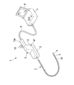
図1に示す内視鏡装置1は、体腔内や機械構造物等に挿入される可撓性で細長の挿入部2と、挿入部2の基端側に設けられていて挿入部2の先端側の湾曲部9を上下左右に湾曲させる操作部3と、内視鏡装置1の電源スイッチや操作手段等を有していてモニタ4を備えたコントローラ5と、操作部3とコントローラ5を接続する可撓性のユニバーサルケーブル6で概略構成されている。Hereinafter, embodiments of the present invention will be described in detail with reference to the drawings.
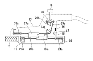
An endoscope apparatus according to a first embodiment of the present invention will be described with reference to FIGS. FIG. 1 is a diagram showing an overall configuration of an endoscope apparatus according to the first embodiment, FIG. 2 is an exploded perspective view of an operation unit, and FIGS. 3 and 4 are diagrams showing a wire connection structure of an insertion unit side housing. 5 and 6 are diagrams showing a wire connection structure of the main body side housing, FIGS. 7A and 7B are perspective views of the main part of the operation lever and exploded views thereof, and FIGS. 8A and 8B are locks of the insertion portion side housing and the main body side housing. FIGS. 9 and 10 are diagrams illustrating the structure of the operation unit before and after locking, and FIGS. 11 to 13 are diagrams illustrating the operation state of the operation lever.
An endoscope apparatus 1 shown in FIG. 1 is provided with a flexible and
内視鏡装置1において、挿入部2は先端側から順に先端部8と、内部に図示しない湾曲駒を連設していて例えば上下左右に湾曲可能な湾曲部9と、柔軟性を有する可撓管10とで構成されている。
操作部3は挿入部側ハウジング(第一の部分)12と本体側ハウジング(第二の部分)13とに分離可能に連結されている(図2参照)。本体側ハウジング13には、その上部開口から操作手段として突出する操作レバー14が保持されていると共に、コントローラ5側に延びる把持部13aが形成されている。駆動部を構成する操作レバー14は例えば前後左右方向に揺動可能であり、これによって後述するワイヤを介して挿入部2の湾曲部9を上下左右方向に湾曲させることができる。
なお、内視鏡装置1は、上述した構成以外に、観察系や照明系の構成も備えているが、本実施形態ではそれらの構成の説明は省略する。In the endoscope apparatus 1, the
The
In addition to the above-described configuration, the endoscope apparatus 1 includes an observation system and an illumination system, but the description of these configurations is omitted in the present embodiment.
次に、操作部3の内部構造について図2乃至図7に基づいて説明する。
図2乃至図4において、操作部3の挿入部側ハウジング12内では長手方向中央部分に複数条、例えば4条のガイド溝16a、16b、16c、16dが形成されたガイド板16が配設され、ガイド板16のガイド溝16a〜16dを挟む両側の枠部16e、16fには本体側ハウジング13と連結するための係止溝17、17が例えば各2条づつ形成されている。係止溝17は縦断面に沿って見た際に垂直部と水平部からなる略L字形状の拡径溝部17aと小幅溝17bとが連通する略四角形状とされている(図8A参照)。
ガイド板16の各ガイド溝16a、16b、16c、16dには、例えば図4に示す二段の階段状段部15Aを上面に形成した略角柱状の第一係合部材19a、19b、19c、19dがそれぞれ前後方向に摺動可能に配設されている。各第一係合部材19a〜19dの内部に設けた貫通孔には第一牽引部材であるアングルワイヤ(以下、単にワイヤという)20a、20b、20c、20dが挿通され、第一係合部材19a〜19dの基端部(コントローラ5側)に固定された口金21によってワイヤ20a〜20dが各第一係合部材19a〜19dに固定されている。Next, the internal structure of the
2 to 4, a
In each
図3において、挿入部2の基端側は挿入部側ハウジング12に連結されており、この連結部で挿入部2内からハウジング12内に延びる4本のアングルコイル22a〜22dはガイド板16の前側即ち挿入部2側に配置された固定板23にそれぞれ口金を介して連結されている。そして、各第一係合部材19a〜19dの前側に延びる各ワイヤ20a〜20dは各アングルコイル22a〜22d内へ延びている。これらのワイヤ20a〜20dは挿入部2内を通過して湾曲部9に配列した湾曲駒の上下左右を通り先端部に固定されている。
ここで、ワイヤ20a〜20dは、例えば各2本のワイヤ20a、20bと20c、20dがそれぞれ組(対)になっており、ワイヤ20a、20bは湾曲部9の先端部(湾曲駒)の上下方向に固定され、ワイヤ20c、20dは湾曲部9の先端部(湾曲駒)の左右方向に固定されている。そのため、ワイヤ20aが引かれるとワイヤ20bが緩んで湾曲駒を介して湾曲部9を上下方向に湾曲させ、ワイヤ20cが引かれるとワイヤ20dが緩んで湾曲部9を左右方向に湾曲させる。
また、第一係合部材20a〜20dの基端側には板状のばね受け25が固定され、ばね受け25には第一付勢部材として例えばコイルスプリング24a〜24dの一端が係止されている。コイルスプリング24a〜24dの他端は第一係合部材19a〜19dの口金21から突出するワイヤ20a〜20dに連結されている。そのため、各第一係止部材19a〜19dはコイルスプリング24a〜24dの付勢力によってワイヤ20a〜20dを牽引した状態で、ガイド溝16a〜16d内に前後方向に摺動可能に保持されている。In FIG. 3, the proximal end side of the
Here, for example, each of the
Further, a plate-
次に本体側ハウジング13の内部構造について図5、図6に基づいて説明する。 本体側ハウジング13においても、挿入部側ハウジング12の内部構造と同様にガイド溝26a〜26dを備えたガイド板26、各ガイド溝26a〜26dに摺動可能に保持された略角柱状の第二係合部材27a〜27d、各第二係合部材27a〜27dの内部に挿通された作動部材または第二牽引部材としての操作ワイヤ29a〜29dを備えている。第二係合部材27a〜27dの表面には二段の階段状段部15Bが形成されている。また、操作ワイヤ29a〜29dは、前端側に固定した口金28を以て各第二係合部材27a〜27dに連結されている。
第二係合部材27a〜27dは挿入部側ハウジング12の第一係合部材19a〜19dの段部15Aと段部15Bにて係合する。段部15A、15Bは段差が少なくとも互いに1つあれば係合できるが、互いに複数設けることで係合状態で生じる回転モーメントを低減できて好ましい。
そして、本体側ハウジング13の前方側即ち挿入部2側に板状のばね受け30が固定され、ばね受け30には第二付勢部材として例えばコイルスプリング31a〜31dの一端が係止され他端は操作ワイヤ29a〜29dに連結されている。これによって、各第二係合部材27a〜27dはコイルスプリング31a〜31dの付勢力によって操作ワイヤ29a〜29dを牽引した状態で、ガイド溝26a〜26d内に前後方向に摺動可能に保持されている。
また、本体側ハウジング13の基端側にはプーリ33a〜33dが、プーリ軸32で回転可能に支持され、各操作ワイヤ29a〜29dは、操作レバー14方向に向きを変えられ、プーリ33a〜33dにそれぞれ巻回されている。Next, the internal structure of the main
The
A plate-
Further, pulleys 33a to 33d are rotatably supported by the
次に操作レバー14による操作ワイヤ29a〜29dの作動機構について図7A及び図7Bに基づいて説明する。
図7A及び図7Bにおいて、操作レバー14は本体側ハウジング13の開口を通してその内部に延伸して、フレーム35で支持されている軸受36によって略十字状に互いに直交するX1−X2方向とY1−Y2方向とに揺動可能とされている。軸受36の下部には固定部40aを介して略十字形状のアーム部37が連結されている。
図7Bに示すように、軸受36は、固定部40aを有する円形軸40と一対の球軸受41,42とで主に構成されている。円形軸40は略円柱形状に形成されており、操作レバー14は円形軸40とアーム部37を貫通している。そして、操作レバー14下部の雄ねじ部にナット38を固着することにより、操作レバー14は円形軸41とアーム部37を同軸に固定している。Next, the operation mechanism of the
7A and 7B, the
As shown in FIG. 7B, the
第1球軸受41と第2球軸受42は半球形状に形成されている。これら第1球軸受41と第2球軸受42の内部には、円形軸40が嵌合配置される円形軸受部41a、42aが形成されている。第1球軸受41及び第2球軸受42には円形軸40に設けられている固定部40aが配置される溝部40Bを構成する第1切り欠き部41b、42b、円形軸41に固定される操作レバー14が配置される溝部40Cを構成する第2切欠部41c,42cがそれぞれ設けられている。さらに、第1球軸受41と第2球軸受42とには、一体化されたとき円柱状の軸部40Dを構成する一対の半円柱部41d、42dが対向する位置に設けられている。
また、アーム部37には、周方向に略90°間隔でX1、X2方向、Y1、Y2方向にそれぞれ延びる4本のアーム部37a、…が突出形成され、各アーム部37aにはワイヤ固定孔37bが穿孔されている。そして、プーリ33a〜33dで巻回されて操作レバー14に向かう操作ワイヤ29a〜29dが各アーム部37aのワイヤ固定孔37bにそれぞれ固定されている。
軸受36は、アーム部材37と操作レバー14とを同軸に取付け固定した円形軸40を、第1球軸受41と第2球軸受42で挟持して構成されている。このため、円形軸40は、溝部40B、40Cの範囲で矢印X1方向及び矢印X2方向に揺動可能である。
また、円形軸40を第1球軸受41及び第2球軸受42で挟持することにより、半円柱部41d、42dが一体になって、同軸をなす軸部40D、40Dが形成される。そして、これら軸部40D、40Dを、フレーム35の所定位置に、回転軸として回動可能に支持される。このため、軸受36は矢印Y1方向及び矢印Y2方向に揺動可能である。The
Further, the
The
Further, by sandwiching the
そのため、操作レバー14を図7Aに示すように直立状態にしたとき、操作ワイヤ29a〜29dのプーリー33a〜33dからアーム部材37に向かう部分は全て所定の弛緩状態になる。この状態で、操作レバー14を図中の矢印X1方向または矢印X2方向、或いは矢印Y1方向又は矢印Y2方向に操作することによって、操作レバー14の傾倒操作とともにアーム部材37が揺動する。
そして、操作レバー14の傾き方向に対応する各アーム部37aの固定孔37bに取り付けられている操作ワイヤ29a〜29dのいずれか、例えば操作ワイヤ29aの張力が弛んでいた状態から引っ張られる状態になると、この操作ワイヤ29aのプーリーに対する抗力が増大し、操作ワイヤ29aとこれを巻回するプーリー33aとの間の抵抗力が増す。一方、対向する操作ワイヤ29bはさらに弛んだ状態になる。Therefore, when the
When one of the
次に、挿入部側ハウジング12と本体側ハウジング13の接続構造を説明する。
図5に示す本体側ハウジング13のガイド板26において、ガイド溝26a〜26dを挟む両側の枠部26e、26fには挿入部側ハウジング12の係止溝17、17と係合するガイドピン34、34が例えば各2個づつ設けられており、ガイド部材を構成する。図8Aに示すように、ガイドピン34は拡径された頭部34aと軸部34bとで構成されている。ガイドピン34の頭部34aは係止溝17の拡径溝部17aには挿入可能であるが小幅溝17bには挿入できない大きさとされている。
そのため、挿入部側ハウジング12と本体側ハウジング13を接続するには、両ハウジング12,13の開口部をずらした状態で対向させてガイドピン34の頭部34aを係止溝17の拡径溝部17aの垂直部に挿入させる。この状態で挿入部側ハウジング12と本体側ハウジング13は互いに段部15Aと段部15Bが離れる方向にずれている。次いで、挿入部側ハウジング12と本体側ハウジング13のいずれかをスライドさせることで、ガイドピン34の頭部34aが係止溝17の略L字形状の拡径溝部17a内の水平部に嵌合して両ハウジング12,13が合致し、接続状態になる。Next, a connection structure between the insertion
In the
Therefore, in order to connect the insertion
次に図8A及び図8Bに基づいて、挿入部側ハウジング12と本体側ハウジング13の位置決め固定機構(ロック構造)を説明する。
図8Aに示す本体側ハウジング13には、プーリ33a〜33dの後方にロック部材としてロックレバー45が設けられている。図8Bにおいて、このロックレバー45は長軸のレバー部45aとこれに略直交する方向に突出するカム軸45bとで構成され、上部に設けた圧縮状態の押しばね46によって下方に付勢されている。レバー部45aは下端面が傾斜面を有するロック爪45cとされている。
本体側ハウジング13の側壁13aを貫通してリリース部材としてリリースボタン47が装着され、このリリースボタン47は先端にリリースカム48が設けられ、リリースカム48の傾斜面状のカム面48aがロックレバー45のカム軸45bを係止している。リリースボタン47の頭部47aは側壁13aの外部に突出しており、頭部47aと側壁13aとの間の軸部47bに戻りばね49が介装されている。リリースボタン47の頭部47aを押すことでカム面48aによってロックレバー45を後退(上昇)させ、頭部47aを引くことで戻りばね49の弾性力でリリースカム48をカム軸45bから後退させる。Next, based on FIG. 8A and FIG. 8B, the positioning fixing mechanism (lock structure) of the insertion
In the main
A
一方、挿入部側ハウジング12においては、ばね受け25の一部にストッパ44が突出して設けられている。そして、挿入部側ハウジング12に対して本体側ハウジング13を接続する際、ロックレバー45は通常では本体側ハウジング13の開口部より下方に突出している。
係止溝17にガイドピン34を挿入した状態で、挿入部側ハウジング12に対して本体側ハウジング13をスライドさせると、ロックレバー45のロック爪45cがストッパ44に当接して押しばね46の付勢力に抗して後退し、ストッパ44を乗り越えて再度降下する。そして、ガイドピン34の頭部34aが係止溝17の拡径溝部17aの水平部の最奥部に到達した状態で、両ハウジング12,13が合致し、ロックレバー45が挿入部側ハウジング12の基端側壁との間でストッパ44に係止し、両ハウジング12,13のズレが防止されたロック状態になる。
ロック状態を解除するには、リリースボタン47を押してロックレバー45をストッパ44から後退させた状態で、ガイドピン34の頭部34aと係止溝17の拡径溝部17a内の水平部との嵌合が解除される方向に、本体側ハウジング13を挿入部側ハウジング12からずらせばよい。On the other hand, in the insertion
When the
To release the lock state, the
本実施形態による内視鏡装置1の操作装置は上述の構成を備えており、次にその作用を説明する。
図1に示す内視鏡装置1によって体腔内や機械構造物の内部を観察、撮像または処置等する場合、操作レバー14をX1、X2、Y1、Y2のいずれかの方向に傾動させることで操作部2の湾曲部9を上下左右のいずれかの方向に湾曲させて任意の方向を向けて観察できる。そして、挿入部2を別の種類のものに交換する場合、図10に示す状態から、リリースボタン47を押すことでロックレバー45を後退させ、ストッパ44との係合を解除させる。
この状態で、挿入部側ハウジング12と本体側ハウジング13とを逆方向に相対的にスライドさせ、本体側ハウジング13のガイドピン34を挿入部側ハウジング12の係止溝17の拡径溝部17aの水平部を移動させる(図9参照)。両ハウジング12、13は水平方向にずれて、ガイドピン34の頭部34aが略L字状の拡径溝部17aの角部に到達した時点で、両ハウジング12、13を互いに離間方向に引き離すことで、ガイドピン34が係止溝17の拡径溝部17の垂直部を移動して分離できる(図8A参照)。The operation device of the endoscope apparatus 1 according to the present embodiment has the above-described configuration, and the operation thereof will be described next.
When the endoscope apparatus 1 shown in FIG. 1 is used to observe, image, or treat a body cavity or the inside of a mechanical structure, the
In this state, the insertion
次に、別の挿入部側ハウジング12を上述の分離工程と逆の工程で本体側ハウジング13と接続させる。具体的には、本体側ハウジング13のガイドピン34を挿入部側ハウジング12の係止溝17の略L字状の拡径溝部17aの垂直部に挿入する(図8A参照)。この時、両ハウジング12,13の開口部同士がずれて当接した状態で、挿入部側ハウジング12の第一係合部材19a〜19dと第二係合部材27a〜27dがガイド溝16a〜16d、26a〜26d内で対向した状態で段部15B,15Aが互いに離間して保持されている。
そして、本体側ハウジング13を挿入部側ハウジング12に対して相対的にスライドさせる。このスライド動作では、ガイドピン34の頭部34aが、挿入部側ハウジング12の係止溝17の拡径溝部17aの水平部を、その延設方向に沿って移動することでガイドされる。これによって、第二係合部材27a〜27dと第一係合部材19a〜19dが段部15B,15Aで当接する。第一及び第二係合部材19a〜19d、27a〜27dはガイド溝16a〜16d、26a〜26dに摺動可能に保持されているため、係合する段部15A、15Bがずれることはない。Next, another insertion
Then, the main
そのため、例えば、アーム部材37の対向するアーム部37a,37aに係止された操作ワイヤ29a及び29b、または操作ワイヤ29c及び29dにおいて一方が緩んだ状態にあり他方が引っ張られた状態にある場合、第二係合部材27a〜27dの一部または全部がスライド方向の前後にずれた位置にあり、これらのずれに従って操作レバー14は傾斜した状態に位置する。
この場合でも、第一係合部材19a〜19d及び第二係合部材27a〜27d同士を互いに当接させることで、操作ワイヤ29a〜29dの緩みや緊張の不均一が解消される。従って、両ハウジング12,13の接続に際して、第一係合部材19a〜19dと第二係合部材27a〜27dについて予め位置調整をしておく必要がない。
このことは、挿入部2の湾曲部9においても同様である。即ち、挿入部側ハウジング12と本体側ハウジング13を接続する際に、湾曲部9が上下左右のいずれかの方向に湾曲していたとしても、本体側ハウジング13のガイドピン34を挿入部側ハウジング12の係止溝17に挿入して第一及び第二係合部材19a〜19d、27a〜27d同士を離間した状態から、スライドさせて互いに当接させることで、ワイヤ20a〜20dの弛みや緊張の不均一が解消される。Therefore, for example, when one of the
Even in this case, the
The same applies to the bending portion 9 of the
次に、挿入部側ハウジング12と本体側ハウジング13が接合した操作部3を用いた内視鏡装置1の操作方法について図11〜図13に基づいて説明する。
上述したように、図11において、操作部3の挿入部側ハウジング12と本体側ハウジング13を連結した状態で、第一及び第二係合部材19a〜19d、27a〜27dが係合して操作レバー14と挿入部2がニュートラルの位置にある。この状態から、図12に示すように、操作レバー14を例えばX1方向に傾動させると、傾動するアーム部材37によって操作ワイヤ29aが引っ張られるためにコイルスプリング31aの付勢力に抗して第二係合部材27aがガイド溝26aに沿って後方にスライドする。そのため、段部15Bで係合する第一係合部材19aが押されてガイド溝16aに沿って後方にスライドしてコイルスプリング24aが圧縮され且つワイヤ20aが引っ張られる。Next, an operation method of the endoscope apparatus 1 using the
As described above, in FIG. 11, the first and
また、操作レバー14及びアーム部材37の傾動によって操作ワイヤ29aと対向する操作ワイヤ29bが弛む。すると、第二係合部材27bがコイルスプリング31bの付勢力で引っ張られて前方へ移動するから第一係合部材19bと離間し、ワイヤ20bへ働く張力も緩む。そのため、上述のように操作レバー14をX1方向に傾動することで、ワイヤ20aが引っ張られることによって挿入部2の先端側の湾曲部9に例えば下方に湾曲する力が付与されると共にワイヤ20bが緩むことによって、湾曲部9は下方に湾曲する。
また、図13に示すように、操作レバー14をX2方向に傾動させると、上述の場合とは逆に操作ワイヤ29bが引っ張られ、操作ワイヤ29aが緩む。これによって第二係合部材27aが第一係合部材19aから離間してワイヤ20aが緩む。これと同時に、第二係合部材27bがコイルスプリング31bの付勢力に抗して第一係合部材19bを押動してワイヤ20bが引っ張られる。これによって挿入部2の先端側の湾曲部9はワイヤ20bが引っ張られると共にワイヤ20aが緩むことで、上方に湾曲する。この際に、ワイヤ20aが遅れて動くことがあり、ワイヤ20aのたるみの原因となり得るが、第二係合部材27aと第一係合部材19aが固定されておらず分離可能であり、無理にワイヤ20aを前方に動かさないので、ワイヤ20aがたるむ不具合が生じない。Further, the
As shown in FIG. 13, when the
このように操作レバー14をX1方向またはX2方向に傾動することで、挿入部2の先端側の湾曲部9を下方または上方へ湾曲できる。同様に、操作レバー14をY1方向またはY2方向に傾動することで、挿入部2の先端側の湾曲部9を左方または右方へ湾曲できる。
By tilting the
上述のように本実施形態による内視鏡装置1の操作装置によれば、一体に連結された挿入部2と挿入部側ハウジング12を本体側ハウジング13に取り付けるだけで別の種類のものに交換して観察や撮像や処置等を実施することができる。
また、ニュートラル位置へのセッティングに際して、挿入部側ハウジング12の係止溝17の拡径溝部17aの垂直部に本体側ハウジング13のガイドピン34を挿入し、両者を互いにずれた位置で対向させた状態から、ガイドピン34を拡径溝部17aの水平部の最奥部にスライドさせた連結状態に移動させるだけで、互いに離間して対向する第一係合部材19a〜19dと第二係合部材27a〜27dを互いに係合させてニュートラル位置にそれぞれを位置調整できる。
そのため、連結前に、操作レバー14がいずれかの方向に傾動した状態であったり挿入部2の湾曲部がいずれかの方向に湾曲した状態であっても、挿入部側ハウジング12と本体側ハウジング13を連結するだけで第一係合部材19a〜19dと第二係合部材27a〜27dの位置ずれを調整してニュートラル状態に位置調整できる。しかも、挿入部2及び挿入部側ハウジング12の交換に際して、操作レバー14と挿入部2のワイヤ20a〜20dを接続する第一及び第二係合部材19a〜19d、27a〜27dをニュートラル位置や特定の位置等に予め位置決めまたは位置合わせしておく必要がなく、単に第一係合部材19a〜19dと第二係合部材27a〜27dを当接させて所要の押圧力を付与するだけでこれら係合部材19a〜19d、27a〜27dの位置ずれを調整してニュートラル状態に位置調整できる。
従って、挿入部側ハウジング12と本体側ハウジング13をスライドさせて連結するだけで操作レバー14と挿入部2の湾曲部9をニュートラル位置にセッティングすることができる。As described above, according to the operation device of the endoscope apparatus 1 according to the present embodiment, the
Further, when setting to the neutral position, the
Therefore, even if the operating
Therefore, the operating
本発明は上述の第一実施形態に限定されることなく本発明の趣旨を逸脱しない範囲で適宜変更可能である。
次に本発明の第二実施形態による内視鏡装置50の操作装置について図14乃至図19に基づいて説明する。なお、上述の実施形態による内視鏡装置1の操作装置と同一または同様な部分、部材には同一の符号を用いて説明を省略する。
図14及び図15は電動湾曲式の内視鏡装置50の要部斜視図であり、本実施形態による電動湾曲式内視鏡装置50では、モータ駆動による電動によって挿入部2の湾曲部9が上下左右方向に湾曲させられるようになっている。図において、挿入部2及び挿入部側ハウジング12は第一実施形態によるものと同一構成である。
モニタ4を備えたコントローラ51には挿入部側ハウジング12を連結接続するための本体側ハウジング52が内蔵されている。すなわち、本実施形態では、コントローラ51と本体側ハウジング52とが一体的に構成されている。また、本体側ハウジング52の近傍には挿入部側ハウジング12を離脱させるためのリリースボタン47が設けられている。リリースボタン47を含む挿入部側ハウジング12と本体側ハウジング52との位置決め固定機構(ロック構造)は操作部3の外部にあるが、上述の第一実施形態によるものと同一である。コントローラ51にはコードを介して操作手段としてリモコン53が設けられ、リモコン53には挿入部2の湾曲部9を上下方向と左右方向に湾曲する操作ボタンが例えば十字キー54として設けられている。十字キー54の4つの端部のいずれかを押すことで湾曲部9を上下左右方向に湾曲操作させることができる。The present invention is not limited to the first embodiment described above, and can be changed as appropriate without departing from the spirit of the present invention.
Next, an operation device of the endoscope apparatus 50 according to the second embodiment of the present invention will be described with reference to FIGS. In addition, the same code | symbol is used for the part and member which are the same as that of the operation apparatus of the endoscope apparatus 1 by the above-mentioned embodiment, or are the same, and description is abbreviate | omitted.
14 and 15 are perspective views of the main part of the electric bending endoscope apparatus 50. In the electric bending endoscope apparatus 50 according to the present embodiment, the bending portion 9 of the
The
本体側ハウジング52の構造について図16乃至図19により説明する。
図16に示す本体側ハウジング52では、挿入部側ハウジング12の内部構造と同様に、その長手方向(図では上下方向)中間部にガイド溝56a〜56dを備えたガイド板56と、各ガイド溝56a〜56dに摺動可能に保持されていて例えば二段の階段状段部15Bを表面に形成した略角柱状の第二係合部材57a〜57dとが設けられている。第二係合部材57a〜57dは各ガイド溝56a〜56d内を上下方向にスライド可能とされている。
第二係合部材57a〜57dは挿入部側ハウジング12の第一係合部材19a〜19dと段部15B,15A同士で係合するもので、段部15A、15Bは少なくとも互いに1つの段差があれば係合できるが、互いに複数設けることで係合面で生じる回転モーメントを低減できて好ましい。The structure of the main
In the main
The second
図17に示すように、各第二係合部材57a〜57dの内部には雌ねじが切られたねじ穴58が第二係合部材57a〜57dの長手方向に貫通して形成され、これら各第二係合部材57a〜57dの各ねじ穴58には直動駆動機構としてスクリュー部材、例えばスクリューネジ59a〜59dが螺合状態で上下に挿通している。これらスクリューネジ59a〜59d等の直動駆動機構は作動部材を構成している。各第二係合部材57a〜57dをそれぞれ螺合するスクリューネジ59a〜59dの上下端部にはそれぞれ上側軸60と下側軸61とがそれぞれ形成されている(図18参照)。図17に示すように、例えば各4本の上側軸60と下側軸61は上部軸受板62と下部軸受板63にそれぞれ設けた貫通孔64、65に回転可能に支持されている。
なお、貫通孔64を有する上部軸受板62と貫通孔65を有する下部軸受板63に代えて各スクリューネジ59a〜59d毎に軸受を設けてもよい。As shown in FIG. 17, a
Instead of the
そして、図17乃至図19に示すように、スクリューネジ59a、59bの下端部には下側軸61の上側に第一平ギヤ67と第二平ギヤ68がそれぞれ固着されており、これら第一平ギヤ67と第二平ギヤ68は互いに噛合している。一方の平ギヤ、例えば第二平ギヤ68にはピニオンギヤ69が噛合されており、このピニオンギヤ69は上下方向移動用の第一モータM1のモータ軸70が同軸に固着されている。なお、これらのギヤ67,68,69を第一連動機構とする。
第一モータM1は正逆回転可能であり、例えば正方向回転によって第二係合部材57aを上方に第二係合部材57bを下方に移動させ、逆方向回転によって第二係合部材57aを下方に第二係合部材57bを上方に移動させるよう第一、第二平ギヤ67,68に回転力を伝達する。
また、スクリューネジ59c、59dの上端部には上側軸60の下側に第三平ギヤ72と第四平ギヤ73がそれぞれ固着されている。そして、例えば第三平ギヤ72には第一連動ギヤ75、第二連動ギヤ76が順次噛合状態で保持され、第四平ギヤ73には第三連動ギヤ77が噛合状態で保持されている。第二連動ギヤ76と第三連動ギヤ77の間にはピニオンギヤ78が噛合状態で保持され、ピニオンギヤ78には左右方向移動用の第二モータM2のモータ軸79が同軸に固着されている。なお、これらのギヤ76,75,72、77、73、78を第二連動機構とする。
第二モータM2も正逆回転可能であり、例えば正方向回転によって第二係合部材57cを左方に第二係合部材57dを右方に移動させ、逆方向回転によって第二係合部材57cを右方に第二係合部材57dを左方に移動させるよう各ギヤ76,75,72、77、73に順次回転力を伝達する。As shown in FIGS. 17 to 19, a first
The first motor M1 can be rotated forward and backward. For example, the
Further, a third
The second motor M2 can also rotate forward and backward. For example, the
また、図19に示すように、第一モータM1は上下方向ポテンショメータ81に電気的に接続されており、このポテンショメータ81では第一モータM1の例えばニュートラル位置を予め記憶しておく。また、第一モータM1の正逆回転による第二係合部材57a、57bのニュートラル位置からの移動位置、即ち湾曲部9のニュートラル位置からの上下方向湾曲角度を計測して記憶しておくこともできる。
同様に、第二モータM2は左右方向ポテンショメータ82に電気的に接続されており、このポテンショメータ82では第二モータM2の例えばニュートラル位置を予め記憶しておく。また、第二モータM2による正逆回転による第二係合部材57c、57dのニュートラル位置からの移動位置、即ち湾曲部9のニュートラル位置からの左右方向湾曲角度を計測して記憶しておくこともできる。
なお、第一、第二モータM1,M2、ポテンショメータ81,82、第一、第二連動機構は駆動部を構成し、第一、第二モータM1,M2は駆動部または駆動源を構成する。第一、第二モータM1,M2は必ずしも本体側ハウジング52内に設けなくてもよく、コントローラ51内に設けていてもよい。
また、図16において、本体側ハウジング52には、ガイド板56におけるガイド溝56a〜56dの両側に枠部56e、56fが設けられ、各一対のガイドピン34,34が植設されている。これらのガイドピン34が挿入部側ハウジング12の係止溝17に嵌合してスライド可能であることは第一実施形態と同様である。
また、本体側ハウジング52において、ガイド板56の上下には上カバー84、下カバー85が設けられており、下カバー85の開口からロックレバー45のロック爪45cが突出している。Further, as shown in FIG. 19, the first motor M1 is electrically connected to a
Similarly, the second motor M2 is electrically connected to the left-
The first and second motors M1 and M2, the
In FIG. 16, the main
In the main
本第二実施形態による電動湾曲式の内視鏡装置50の操作装置は上述の構成を備えており、次にその作用を説明する。
まず、挿入部側ハウジング12を含む挿入部2を他の種類の挿入部2に交換する場合、コントローラ51のリリースボタン47を押すとロックレバー45のロック爪45cが後退して挿入部側ハウジング12のストッパ44との係合が解除される。これと同時に挿入部側ハウジング12を上方にスライドさせると、本体側ハウジング52のガイドピン34に対し挿入部側ハウジング12の係止溝17がスライドし、挿入部側ハウジング12を本体側ハウジング52から外すことができる。
次に装着したい挿入部2を備えた本体側ハウジング12について、係止溝17を本体側ハウジング52のガイドピン34に装着して本体側ハウジング52に沿ってスライドさせることで、ロックレバー45のロック爪45cがストッパ44を乗り越えて係止溝17及びガイドピン34と共にロック状態に装着固定できる。The operation device of the electric bending endoscope device 50 according to the second embodiment has the above-described configuration, and the operation thereof will be described next.
First, when the
Next, with respect to the main
新たな挿入部側ハウジング12を本体側ハウジング52に装着した状態において、コントローラ51に装着された本体側ハウジング52のガイド溝56a〜56d内の適宜位置に保持された第二係合部材57a〜57dはスクリューネジ59a〜59dに螺合しているために、挿入部側ハウジング12の第一係合部材19a〜19dは第二係合部材57a〜57dに当接することで強制的に位置決めされる。この場合の第一係合部材19a〜19dの位置は、コイルスプリング24a〜24dの付勢力によって調整される。
このとき、湾曲部9がいずれかの方向に湾曲していて左右または上下方向の第一係合部材19a〜19dの一組または二組がニュートラル位置にないためにこれらのワイヤに弛みと引っ張りが生じていても、第一係合部材19a〜19dが第二係合部材57a〜57dのいずれかに当接することで位置調整される。
そして、十字キー54を操作することで第一モータM1、第二モータM2を駆動させることによって各第二係合部材57a〜57dをポテンショメータ81,82に記憶されているニュートラル位置に移動させると、第一係合部材19a〜19dもコイルスプリング24a〜24dの付勢力によって張力を調整されながら追従してニュートラル位置に移動させられる。In a state where the new insertion
At this time, since the bending portion 9 is bent in either direction, and one or two sets of the first engaging
Then, by operating the cross key 54 to drive the first motor M1 and the second motor M2, the
次に、図14に示す内視鏡装置50によって体腔内や機械構造物の内部を観察等する場合、リモコン53の十字キー54のいずれかの端部を押すことで上下方向移動用の第一モータM1または左右方向移動用の第二モータM2を駆動させて、挿入部2の湾曲部9を湾曲させる。
例えば、十字キー54によって第二モータM2を正方向回転させると、ピニオンギヤ78の回転を第二、第一連動ギヤ76,75を介して第三平ギヤ72に伝達させ、第三平ギヤ72と一体にスクリューネジ59dを一方向に回転させて第二係合部材57dを上方に移動させる。これと同時に第三連動ギヤ77を介して第四平ギヤ73に回転を伝達させ、第四平ギヤ72と同期してスクリューネジ59cを逆方向に回転させて第二係合部材57cを下方に移動させる。
すると、第二係合部材57c、57dの上下動に連動して、挿入部側ハウジング12の第一係合部材19d、19cが上下動するために、ワイヤ20dが緩みワイヤ20cが引っ張られ、挿入部2の湾曲部9が左方向または右方向に湾曲させられる。十字キー54の他の端部を押圧した場合にも同様な作用によって挿入部2の湾曲部9が適宜の方向に湾曲させられる。Next, when observing the inside of a body cavity or the inside of a mechanical structure with the endoscope apparatus 50 shown in FIG. 14, by pressing any one end of the
For example, when the second motor M2 is rotated in the forward direction by the cross key 54, the rotation of the
Then, in conjunction with the vertical movement of the
本第二実施形態による内視鏡装置50においても、コントローラ51に装着された本体側ハウジング52に対して挿入部側ハウジング12を装着することで、本体側ハウジング52のガイド溝56a〜56d内の適宜位置に保持された第二係合部材57a〜57dに対し、挿入部側ハウジング12の第一係合部材19a〜19dをスライドさせて段部15A、15B同士で当接させる。
本実施形態においては、第一係合部材19a〜19dの停止位置はスクリューネジ59a〜59dに螺合する第二係合部材57a〜57dに当接する位置によって強制的に決められる。そのため、第一モータM1、第二モータM2のニュートラル位置を予め設定しておくことで、挿入部側ハウジング12の交換時に第二係合部材57a〜57dの任意位置に応じた第一係合部材19a〜19dの位置決めを自動的に行え、湾曲部9の真っ直ぐな位置(ニュートラル位置)を自動的に設定できる。Also in the endoscope apparatus 50 according to the second embodiment, the insertion
In the present embodiment, the stop positions of the
上述のように本第二実施形態による内視鏡装置50の操作装置によっても、一体に連結された挿入部2と挿入部側ハウジング12を本体側ハウジング52に取り付けるだけで別の種類のものに交換して観察や撮影等することができる。その際、本体側ハウジング52に設けた第二係合部材57a〜57dが任意の位置にあっても、第二係合部材57a〜57dの位置に応じて第一係合部材19a〜19dの当接位置が決定され、この当接位置に応じた湾曲角度に湾曲部9を湾曲保持できる。そして、各モータM1、M2をニュートラル位置に駆動すれば挿入部2を真っ直ぐなニュートラル位置に自動的に調整できる。
そのため、挿入部側ハウジング12の交換装着時に、第一係合部材19a〜19dと第二係合部材57a〜57dを位置合わせしなくても自動的に位置調整できる。
また、取り外す側である交換部品としての挿入部側ハウジング12にエンコーダを設置する必要が無いので、その構造が簡単となり低価格化にもつながる。As described above, even with the operation device of the endoscope apparatus 50 according to the second embodiment, the
Therefore, the position can be automatically adjusted without aligning the
Moreover, since it is not necessary to install an encoder in the insertion
なお、上述の第一実施形態では、第一及び第二係合部材19a〜19d、27a〜27dはコイルスプリング24a〜24d、31a〜31d等の第一及び第二付勢部材に接続された構成とし、第二実施形態では第一係合部材19a〜19dがコイルスプリング24a〜24dに接続された構成としたが、第一及び第二係合部材19a〜19d、27a〜27dが前後方向に摺動可能に保持される構成であれば、必ずしもコイルスプリング24a〜24d、31a〜31dを設けなくてもよい。この場合でも、第一係合部材19a〜19dと第二係合部材27a〜27dを係合状態に保持することで、上述の各実施形態によるものと同様な操作を行える。
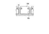
例えば、第一係合部材19a〜19d、第二係合部材27a〜27dを図20A及び図20Bに示すようにガイド溝16a〜16d、26a〜26dから離脱できないように保持されている構成を採用してもよい。或いは第一及び第二係合部材が磁力やコロ等でガイド溝内に摺動可能に保持されていてもよい。In the first embodiment described above, the first and second engaging
For example, the structure which hold | maintains the
また、ワイヤ20a〜20dは第一係合部材19a〜19bと固定されていなくてもよく、ワイヤ20a〜20dと第一係合部材19a〜19bとの間で力を伝達できるように何等かの連動部材が設けられていればよい。操作ワイヤ29a〜29dと第二係合部材27a〜27dとの関係についても同様である。
なお、上述の各実施形態では、ワイヤ20a〜20d及び第一係合部材19a〜19bと、操作ワイヤ29a〜29d及び第二係合部材27a〜27dとを4組設けて挿入部2を上下左右に湾曲操作できるようにしたが、本発明はこのような構成に限定されない。例えば、各1つのワイヤ及び操作ワイヤ、第一及び第二係合部材で構成して1方向にのみ挿入部2を湾曲できるようにしてもよく、或いは2つ以上適宜の複数設けて複数方向に湾曲できるようにしてもよい。また、ワイヤ20a〜20d及び第一係合部材19a〜19b、操作ワイヤ29a〜29d及び第二係合部材27a〜27dについて上下または左右方向の1組のみ設けるようにしてもよく、上下及び左右方向の2組またはそれ以上設けるようにしてもよい。
また、上述の第一の実施形態では、本体側ハウジング13が操作部3に設けられ、上述の第二の実施形態では、本体側ハウジング52がコントローラ51内に一体的に内蔵されている。しかしながら、本発明の「第二の部分」において、内視鏡装置を構成する他の部材と区別された「ハウジング」としての構造は必須ではない。すなわち、本発明の「第二の部分」の具体的な形状、設置部位等は、「第二の部分」として所望の機能を有することが可能であれば、特に限定されない。
また、本発明による挿入部の操作装置は内視鏡に限定されることなく他の処置具等にも適用できる。Further, the
In each of the above-described embodiments, four sets of the
Further, in the first embodiment described above, the main
Moreover, the operating device for the insertion portion according to the present invention is not limited to an endoscope, and can be applied to other treatment tools.
以上説明した通り、本発明によれば、内視鏡やその他の処置具等の挿入部を湾曲作動させるための内視鏡装置において、挿入部を、その位置合わせ等を行なわず容易に交換することが可能となる。 As described above, according to the present invention, in an endoscope apparatus for bending the insertion portion of an endoscope or other treatment instrument, the insertion portion is easily exchanged without performing positioning or the like. It becomes possible.
Claims (14)
第一の部分に着脱可能な第二の部分と、
第二の部分側に設けられて前記湾曲部を湾曲動作させるための駆動部とを備え、
前記第一の部分は、
前記湾曲部に接続されて前記湾曲部を湾曲動作させる第一牽引部材と、
第一牽引部材に接続されて第一牽引部材の長手方向に進退可能な第一係合部材とを備え、
前記第二の部分は、
前記駆動部に接続されている作動部材と、
作動部材に接続されて前記第一牽引部材の長手方向に進退可能で前記第一係合部材に係合可能な第二係合部材とを備え、
前記第一係合部材と前記第二係合部材を係合させることで、前記駆動部の作動を挿入部の湾曲部に伝達する内視鏡装置。A first portion in communication with the insert having a bendable bend;
A second part removable from the first part;
A drive part provided on the second part side for bending the bending part,
The first part is
A first pulling member connected to the bending portion to cause the bending portion to bend;
A first engaging member connected to the first pulling member and capable of moving back and forth in the longitudinal direction of the first pulling member;
The second part is
An actuating member connected to the drive unit;
A second engaging member connected to the operating member and capable of moving forward and backward in the longitudinal direction of the first pulling member and engageable with the first engaging member;
An endoscope apparatus that transmits the operation of the drive unit to the bending portion of the insertion portion by engaging the first engagement member and the second engagement member.
前記位置決め固定機構により、前記第一の部分と前記第二の部分とを位置決め固定することで前記第一係合部材と第二係合部材を係合させる請求項1に記載の内視鏡装置。A positioning and fixing mechanism for positioning and fixing the first part and the second part;
The endoscope apparatus according to claim 1, wherein the first engagement member and the second engagement member are engaged by positioning and fixing the first portion and the second portion by the positioning and fixing mechanism. .
前記第二の部分が、前記第二係合部材を作動部材と反対側に付勢状態で接続する第二付勢部材を備え、前記作動部材は第二牽引部材である請求項1に記載の内視鏡装置。The first portion includes a first biasing member that connects the first engagement member to a side opposite to the first pulling member in a biased state;
The said 2nd part is equipped with the 2nd biasing member which connects the said 2nd engagement member to the opposite side to an operation member in an urging | biasing state, The said operation member is a 2nd traction member. Endoscopic device.
前記作動部材は前記第二係合部材を前記長手方向に進退させる直動駆動機構である請求項1に記載の内視鏡装置。The first portion includes a first biasing member that connects the first engagement member to a side opposite to the first pulling member in a biased state;
The endoscope apparatus according to claim 1, wherein the operating member is a linear drive mechanism that moves the second engagement member forward and backward in the longitudinal direction.
前記ガイド部材と係止溝が係合した状態で、前記第一係合部材と第二係合部材が係合状態になる請求項1に記載の内視鏡装置。A guide member is provided on one of the first part and the second part, and a locking groove on which the guide member can be engaged is provided on the other.
The endoscope apparatus according to claim 1, wherein the first engagement member and the second engagement member are in an engaged state in a state where the guide member and the locking groove are engaged.
湾曲可能な湾曲部を有する前記挿入部と連通する第一の部分と、
第一の部分に着脱可能な第二の部分と、
第二の部分内に設けられて前記湾曲部を湾曲動作させるための操作手段とを備え、
前記第一の部分は、前記湾曲部に接続されて前記湾曲部を湾曲動作させる第一牽引部材と、第一牽引部材に接続されて第一牽引部材の長手方向に進退可能な第一係合部材とを備え、
前記第二の部分は、前記操作手段に接続されている第二牽引部材と、第二牽引部材に接続されて第二牽引部材の長手方向に進退可能で前記第一係合部材に係合可能な第二係合部材とを備え、
前記第一の部分と前記第二の部分を連結して前記第一係合部材と第二係合部材を係合させることで、前記操作手段の作動を挿入部の湾曲部に伝達する内視鏡装置。In an endoscope apparatus provided with an insertion part having an observation system and an illumination system,
A first portion in communication with the insertion portion having a bendable bending portion;
A second part removable from the first part;
An operating means provided in the second portion for bending the bending portion;
The first portion includes a first traction member that is connected to the bending portion and causes the bending portion to bend, and a first engagement that is connected to the first traction member and can be advanced and retracted in the longitudinal direction of the first traction member. With members,
The second portion is connected to the operating means, and is connected to the second pulling member so that the second portion can move forward and backward in the longitudinal direction of the second pulling member and engage with the first engaging member. A second engaging member,
An internal view that transmits the operation of the operation means to the bending portion of the insertion portion by connecting the first portion and the second portion and engaging the first engagement member and the second engagement member. Mirror device.
湾曲可能な湾曲部を有する前記挿入部と連通する第一の部分と、
第一の部分に着脱可能な第二の部分と、
第二の部分側に設けられて前記湾曲部を湾曲動作させるための駆動源とを備え、
前記第一の部分は、前記湾曲部に接続されて湾曲部を湾曲動作させる第一牽引部材と、第一牽引部材に接続されていて第一牽引部材の長手方向に進退可能な第一係合部材とを備え、
前記第二の部分は、前記駆動源に接続されている直動駆動機構と、直動駆動機構に連動してその長手方向に進退可能で前記第一係合部材に係合可能な第二係合部材とを備え、
前記第一の部分と前記第二の部分を連結して前記第一係合部材と第二係合部材を係合させることで、前記駆動源の駆動を挿入部の湾曲部に伝達する内視鏡装置。In an endoscope apparatus provided with an insertion part having an observation system and an illumination system,
A first portion in communication with the insertion portion having a bendable bending portion;
A second part removable from the first part;
A drive source provided on the second part side for bending the bending portion;
The first portion includes a first traction member that is connected to the bending portion and causes the bending portion to bend, and a first engagement that is connected to the first traction member and can be advanced and retracted in the longitudinal direction of the first traction member. With members,
The second portion includes a linear motion drive mechanism connected to the drive source, and a second engagement that is movable in the longitudinal direction in conjunction with the linear motion drive mechanism and engageable with the first engagement member. With a joint member,
An internal view that transmits the drive of the drive source to the bending portion of the insertion portion by connecting the first portion and the second portion and engaging the first engagement member and the second engagement member. Mirror device.
Priority Applications (1)
| Application Number | Priority Date | Filing Date | Title |
|---|---|---|---|
| JP2009532223A JP5160549B2 (en) | 2007-09-11 | 2008-09-11 | Endoscope device |
Applications Claiming Priority (4)
| Application Number | Priority Date | Filing Date | Title |
|---|---|---|---|
| JP2007235475 | 2007-09-11 | ||
| JP2007235475 | 2007-09-11 | ||
| JP2009532223A JP5160549B2 (en) | 2007-09-11 | 2008-09-11 | Endoscope device |
| PCT/JP2008/066454 WO2009035051A1 (en) | 2007-09-11 | 2008-09-11 | Endoscope device |
Publications (2)
| Publication Number | Publication Date |
|---|---|
| JPWO2009035051A1 true JPWO2009035051A1 (en) | 2010-12-24 |
| JP5160549B2 JP5160549B2 (en) | 2013-03-13 |
Family
ID=40452058
Family Applications (1)
| Application Number | Title | Priority Date | Filing Date |
|---|---|---|---|
| JP2009532223A Expired - Fee Related JP5160549B2 (en) | 2007-09-11 | 2008-09-11 | Endoscope device |
Country Status (5)
| Country | Link |
|---|---|
| US (1) | US20100160730A1 (en) |
| EP (1) | EP2189103A4 (en) |
| JP (1) | JP5160549B2 (en) |
| CN (1) | CN101795616A (en) |
| WO (1) | WO2009035051A1 (en) |
Families Citing this family (41)
| Publication number | Priority date | Publication date | Assignee | Title |
|---|---|---|---|---|
| JP5484483B2 (en) * | 2008-12-10 | 2014-05-07 | アンブ・エ/エス | Endoscope bending part control mechanism |
| WO2012027581A2 (en) * | 2010-08-27 | 2012-03-01 | Massachusetts Institute Of Technology | Tip actuated disposable endoscope |
| US9888832B2 (en) * | 2010-09-24 | 2018-02-13 | Blink Device LLC | Endotracheal intubation device |
| TWI457150B (en) * | 2010-10-29 | 2014-10-21 | Univ Nat Cheng Kung | Magnetic navigation control apparatus |
| CN103327874B (en) * | 2011-02-28 | 2016-03-09 | 奥林巴斯株式会社 | Endoscope and armarium |
| ES2606310T3 (en) * | 2011-08-03 | 2017-03-23 | Alcon Research, Ltd. | Articulated ophthalmic surgical probe |
| WO2013018896A1 (en) | 2011-08-03 | 2013-02-07 | オリンパス株式会社 | Wire-pulling mechanism and endoscopic apparatus |
| JP6012950B2 (en) * | 2011-10-14 | 2016-10-25 | オリンパス株式会社 | Bending motion system |
| CN104027061B (en) * | 2012-04-24 | 2016-07-06 | 王东 | Soft endoscope system based on automatically controlled driving instruments |
| JP6137785B2 (en) * | 2012-05-31 | 2017-05-31 | キヤノン株式会社 | Medical instrument and bending deformation device |
| JP6315879B2 (en) | 2012-05-31 | 2018-04-25 | キヤノン株式会社 | Separable medical instrument, operated part of the medical instrument, and operating part of the medical instrument |
| US20140018620A1 (en) * | 2012-07-13 | 2014-01-16 | Fortimedix B.V. | Steerable tube for endoscopic applications |
| DE102012108076A1 (en) | 2012-08-31 | 2014-03-06 | Karl Storz Gmbh & Co. Kg | Shaft for a flexible endoscope or a flexible endoscopic instrument |
| CN104582558B (en) * | 2012-10-22 | 2016-08-31 | 奥林巴斯株式会社 | Endoscope |
| JP5657843B1 (en) * | 2013-02-07 | 2015-01-21 | オリンパスメディカルシステムズ株式会社 | Endoscope operation unit structure |
| CN103315781B (en) * | 2013-07-10 | 2015-03-18 | 上海交通大学 | Endoscope noninvasive surgery system |
| US20170127911A1 (en) * | 2014-03-19 | 2017-05-11 | Endomaster Pte Ltd | Master - slave flexible robotic endoscopy system |
| US10743750B2 (en) | 2014-04-28 | 2020-08-18 | Massachusetts Institute Of Technology | Multi-link modular continuum robotic endoscope system |
| WO2015166877A1 (en) * | 2014-04-28 | 2015-11-05 | オリンパス株式会社 | Operating mechanism for insertion device, and insertion device |
| CN105942958B (en) * | 2016-05-30 | 2018-06-19 | 上海熠达光电科技有限公司 | Endoscope bent angle manipulates rocking bar and endoscope |
| CA3057946A1 (en) * | 2017-03-30 | 2018-10-04 | Shifamed Holdings, Llc | Medical tool positioning devices, systems, and methods of use and manufacture |
| CN107397525B (en) * | 2017-08-29 | 2023-07-18 | 广州瑞派医疗器械有限责任公司 | Electronic cystoscope with rotatable insertion head |
| KR102281120B1 (en) * | 2019-04-10 | 2021-07-26 | 주식회사 이지엔도서지컬 | Endoscope module and modular endoscope device comprising thereof |
| CN110840372A (en) * | 2019-10-15 | 2020-02-28 | 张茹 | Endoscope of easy operation formula |
| US11730349B2 (en) * | 2019-10-25 | 2023-08-22 | Canon U.S.A., Inc. | Steerable medical device with bending sections and improved connector therefor |
| WO2021084577A1 (en) * | 2019-10-28 | 2021-05-06 | オリンパス株式会社 | Endoscope |
| CN110897591B (en) * | 2019-12-31 | 2025-01-07 | 湖南省华芯医疗器械有限公司 | A multi-directional endoscope |
| CA3173336A1 (en) * | 2020-04-08 | 2021-10-14 | Boston Scientific Scimed, Inc. | Locking mechanisms for endoscopic devices |
| CN114391789B (en) * | 2021-01-12 | 2025-01-03 | 常州朗合医疗器械有限公司 | Endoscope handle and drive device |
| GB2606728A (en) | 2021-05-18 | 2022-11-23 | Rolls Royce Plc | A mechanism |
| GB2606727B (en) | 2021-05-18 | 2023-11-08 | Rolls Royce Plc | Actuator |
| US12086544B2 (en) * | 2021-09-17 | 2024-09-10 | Rakuten Mobile, Inc. | Sentiment analysis |
| KR102397647B1 (en) * | 2021-12-08 | 2022-05-16 | 주식회사 메디인테크 | Endoscope having Power Receiving Part |
| KR102459056B1 (en) * | 2021-12-08 | 2022-10-27 | 주식회사 메디인테크 | Power Provider for Medical Device having Response Accuracy |
| KR102434476B1 (en) * | 2021-12-08 | 2022-08-22 | 주식회사 메디인테크 | Endoscope having Tension Controller |
| KR102427943B1 (en) * | 2021-12-08 | 2022-08-03 | 주식회사 메디인테크 | Power Provider for Medical Device |
| KR102427945B1 (en) | 2021-12-08 | 2022-08-03 | 주식회사 메디인테크 | Power Provider for Medical Device having Rear Support |
| KR102443789B1 (en) * | 2021-12-08 | 2022-09-19 | 주식회사 메디인테크 | Endoscope controlled by power receptor |
| KR102496047B1 (en) * | 2021-12-08 | 2023-02-07 | 주식회사 메디인테크 | Endoscope having Power Transmission Part |
| EP4424228A1 (en) * | 2023-03-03 | 2024-09-04 | Cook Medical Technologies LLC | Endoscope handle steering controls |
| CN116327101A (en) * | 2023-04-12 | 2023-06-27 | 上海卓昕医疗科技有限公司 | a bronchoscope |
Family Cites Families (5)
| Publication number | Priority date | Publication date | Assignee | Title |
|---|---|---|---|---|
| US8888688B2 (en) | 2000-04-03 | 2014-11-18 | Intuitive Surgical Operations, Inc. | Connector device for a controllable instrument |
| JP3917894B2 (en) * | 2002-05-17 | 2007-05-23 | オリンパス株式会社 | Traction member operation device |
| JP4323150B2 (en) | 2002-09-30 | 2009-09-02 | オリンパス株式会社 | Electric bending endoscope |
| JP2007000427A (en) * | 2005-06-24 | 2007-01-11 | Olympus Medical Systems Corp | Endoscope |
| JP2007235475A (en) | 2006-02-28 | 2007-09-13 | Murata Mach Ltd | Image reader |
-
2008
- 2008-09-11 EP EP08830584A patent/EP2189103A4/en not_active Withdrawn
- 2008-09-11 JP JP2009532223A patent/JP5160549B2/en not_active Expired - Fee Related
- 2008-09-11 WO PCT/JP2008/066454 patent/WO2009035051A1/en not_active Ceased
- 2008-09-11 CN CN200880106140A patent/CN101795616A/en active Pending
-
2010
- 2010-03-08 US US12/719,195 patent/US20100160730A1/en not_active Abandoned
Also Published As
| Publication number | Publication date |
|---|---|
| EP2189103A1 (en) | 2010-05-26 |
| CN101795616A (en) | 2010-08-04 |
| EP2189103A4 (en) | 2013-01-23 |
| JP5160549B2 (en) | 2013-03-13 |
| WO2009035051A1 (en) | 2009-03-19 |
| US20100160730A1 (en) | 2010-06-24 |
Similar Documents
| Publication | Publication Date | Title |
|---|---|---|
| JP5160549B2 (en) | Endoscope device | |
| JP4350755B2 (en) | Detachable electric bending endoscope | |
| JP4674214B2 (en) | Insertable / detachable electric bending endoscope device | |
| KR102160753B1 (en) | Endoscope device | |
| CN2922781Y (en) | Endoscope | |
| JP4197877B2 (en) | Electric bending endoscope apparatus and calibration method | |
| US8409079B2 (en) | Electric bending operation device and medical treatment system including electric bending operation device | |
| JP6081309B2 (en) | Medical manipulator | |
| JP5047689B2 (en) | Electric bending endoscope | |
| JP7061584B2 (en) | Endoscope | |
| EP2901948A1 (en) | Brake release mechanism and medical manipulator provided with same | |
| US20090287043A1 (en) | Electric medical instrument fitting which is attached to a medical instrument holding device | |
| JP2007000427A (en) | Endoscope | |
| WO2013108776A1 (en) | Insertion device | |
| CN100496376C (en) | endoscope | |
| JP6042678B2 (en) | Brake mechanism and medical manipulator having the same | |
| CN112472006B (en) | Endoscope with chain locking prevention function | |
| JP2011177383A (en) | Operation wire connecting device of endoscope, and endoscope | |
| JP4454956B2 (en) | Endoscope | |
| JP4267017B2 (en) | Endoscope | |
| US20240407866A1 (en) | Continuum robot | |
| JP2013158569A (en) | Endoscope | |
| CN100558287C (en) | Insertion part detachable electric bending endoscope device | |
| CN100577085C (en) | Insertion part detachable electric curved endoscope | |
| US20050033116A1 (en) | Endoscope apparatus |
Legal Events
| Date | Code | Title | Description |
|---|---|---|---|
| A521 | Request for written amendment filed |
Free format text: JAPANESE INTERMEDIATE CODE: A523 Effective date: 20110829 |
|
| A621 | Written request for application examination |
Free format text: JAPANESE INTERMEDIATE CODE: A621 Effective date: 20110829 |
|
| A521 | Request for written amendment filed |
Free format text: JAPANESE INTERMEDIATE CODE: A523 Effective date: 20120316 |
|
| TRDD | Decision of grant or rejection written | ||
| A01 | Written decision to grant a patent or to grant a registration (utility model) |
Free format text: JAPANESE INTERMEDIATE CODE: A01 Effective date: 20121204 |
|
| A61 | First payment of annual fees (during grant procedure) |
Free format text: JAPANESE INTERMEDIATE CODE: A61 Effective date: 20121212 |
|
| R151 | Written notification of patent or utility model registration |
Ref document number: 5160549 Country of ref document: JP Free format text: JAPANESE INTERMEDIATE CODE: R151 |
|
| FPAY | Renewal fee payment (event date is renewal date of database) |
Free format text: PAYMENT UNTIL: 20151221 Year of fee payment: 3 |
|
| S531 | Written request for registration of change of domicile |
Free format text: JAPANESE INTERMEDIATE CODE: R313531 |
|
| R350 | Written notification of registration of transfer |
Free format text: JAPANESE INTERMEDIATE CODE: R350 |
|
| R250 | Receipt of annual fees |
Free format text: JAPANESE INTERMEDIATE CODE: R250 |
|
| R250 | Receipt of annual fees |
Free format text: JAPANESE INTERMEDIATE CODE: R250 |
|
| LAPS | Cancellation because of no payment of annual fees |