CN116327101A - a bronchoscope - Google Patents
a bronchoscope Download PDFInfo
- Publication number
- CN116327101A CN116327101A CN202310386365.1A CN202310386365A CN116327101A CN 116327101 A CN116327101 A CN 116327101A CN 202310386365 A CN202310386365 A CN 202310386365A CN 116327101 A CN116327101 A CN 116327101A
- Authority
- CN
- China
- Prior art keywords
- bending
- channel
- mounting seat
- bronchoscope
- hose
- Prior art date
- Legal status (The legal status is an assumption and is not a legal conclusion. Google has not performed a legal analysis and makes no representation as to the accuracy of the status listed.)
- Pending
Links
Images









Classifications
-
- A—HUMAN NECESSITIES
- A61—MEDICAL OR VETERINARY SCIENCE; HYGIENE
- A61B—DIAGNOSIS; SURGERY; IDENTIFICATION
- A61B1/00—Instruments for performing medical examinations of the interior of cavities or tubes of the body by visual or photographical inspection, e.g. endoscopes; Illuminating arrangements therefor
- A61B1/267—Instruments for performing medical examinations of the interior of cavities or tubes of the body by visual or photographical inspection, e.g. endoscopes; Illuminating arrangements therefor for the respiratory tract, e.g. laryngoscopes, bronchoscopes
-
- A—HUMAN NECESSITIES
- A61—MEDICAL OR VETERINARY SCIENCE; HYGIENE
- A61B—DIAGNOSIS; SURGERY; IDENTIFICATION
- A61B1/00—Instruments for performing medical examinations of the interior of cavities or tubes of the body by visual or photographical inspection, e.g. endoscopes; Illuminating arrangements therefor
- A61B1/005—Flexible endoscopes
- A61B1/0051—Flexible endoscopes with controlled bending of insertion part
- A61B1/0052—Constructional details of control elements, e.g. handles
-
- A—HUMAN NECESSITIES
- A61—MEDICAL OR VETERINARY SCIENCE; HYGIENE
- A61B—DIAGNOSIS; SURGERY; IDENTIFICATION
- A61B1/00—Instruments for performing medical examinations of the interior of cavities or tubes of the body by visual or photographical inspection, e.g. endoscopes; Illuminating arrangements therefor
- A61B1/005—Flexible endoscopes
- A61B1/0051—Flexible endoscopes with controlled bending of insertion part
- A61B1/0055—Constructional details of insertion parts, e.g. vertebral elements
-
- A—HUMAN NECESSITIES
- A61—MEDICAL OR VETERINARY SCIENCE; HYGIENE
- A61B—DIAGNOSIS; SURGERY; IDENTIFICATION
- A61B1/00—Instruments for performing medical examinations of the interior of cavities or tubes of the body by visual or photographical inspection, e.g. endoscopes; Illuminating arrangements therefor
- A61B1/005—Flexible endoscopes
- A61B1/0051—Flexible endoscopes with controlled bending of insertion part
- A61B1/0057—Constructional details of force transmission elements, e.g. control wires
-
- Y—GENERAL TAGGING OF NEW TECHNOLOGICAL DEVELOPMENTS; GENERAL TAGGING OF CROSS-SECTIONAL TECHNOLOGIES SPANNING OVER SEVERAL SECTIONS OF THE IPC; TECHNICAL SUBJECTS COVERED BY FORMER USPC CROSS-REFERENCE ART COLLECTIONS [XRACs] AND DIGESTS
- Y02—TECHNOLOGIES OR APPLICATIONS FOR MITIGATION OR ADAPTATION AGAINST CLIMATE CHANGE
- Y02A—TECHNOLOGIES FOR ADAPTATION TO CLIMATE CHANGE
- Y02A50/00—TECHNOLOGIES FOR ADAPTATION TO CLIMATE CHANGE in human health protection, e.g. against extreme weather
- Y02A50/30—Against vector-borne diseases, e.g. mosquito-borne, fly-borne, tick-borne or waterborne diseases whose impact is exacerbated by climate change
Landscapes
- Health & Medical Sciences (AREA)
- Life Sciences & Earth Sciences (AREA)
- Surgery (AREA)
- Radiology & Medical Imaging (AREA)
- Engineering & Computer Science (AREA)
- Veterinary Medicine (AREA)
- Biophysics (AREA)
- Nuclear Medicine, Radiotherapy & Molecular Imaging (AREA)
- Optics & Photonics (AREA)
- Pathology (AREA)
- Public Health (AREA)
- General Health & Medical Sciences (AREA)
- Physics & Mathematics (AREA)
- Biomedical Technology (AREA)
- Heart & Thoracic Surgery (AREA)
- Medical Informatics (AREA)
- Molecular Biology (AREA)
- Animal Behavior & Ethology (AREA)
- Otolaryngology (AREA)
- Physiology (AREA)
- Pulmonology (AREA)
- Endoscopes (AREA)
Abstract
本发明提供一种支气管镜,包括插入管和调弯器械盒,插入管内设有钳道管和多根调弯丝。调弯器械盒包括安装座和多个控弯部件。安装座内设有安装腔;安装腔内设有内部通道,安装座上设有连通外界和安装腔的安装通道,插入管安装于安装通道内且钳道管与内部通道的一端对接,钳道管和内部通道形成器械通道,内部通道的另一端穿设安装座并于安装座外形成器械通道的入口。多个控弯部件与多根调弯丝一一对应;控弯部件安装于安装腔内且与其转动连接,调弯丝的近端绕设对应控弯部件后与其固定连接。控弯部件的输出端为传动卡爪,传动卡爪伸出安装腔位于安装座外,传动卡爪用于与外部动力端卡盘对接,由外部动力端卡盘驱动实现转动以控制对应调弯丝的收放。
The invention provides a bronchoscope, which comprises an insertion tube and a bending adjustment instrument box. The insertion tube is provided with a forceps tube and a plurality of bending adjustment wires. The bending adjustment instrument box includes a mounting seat and a plurality of bending control parts. There is an installation cavity in the installation seat; an internal channel is provided in the installation cavity, and an installation channel connecting the outside world and the installation cavity is provided on the installation seat. The insertion tube is installed in the installation channel and the clamp tube is docked with one end of the internal channel, and the clamp channel The tube and the internal channel form an instrument channel, and the other end of the internal channel passes through the mounting seat and forms an entrance of the instrument channel outside the mounting seat. A plurality of bending control parts corresponds to a plurality of bending adjustment wires one by one; the bending control parts are installed in the installation cavity and connected to them in rotation, and the proximal ends of the bending adjustment wires are wound around the corresponding bending control parts and then fixedly connected to them. The output end of the bending control part is the transmission claw, which extends out of the installation cavity and is located outside the installation seat. The transmission claw is used to dock with the external power end chuck, and the external power end chuck drives the rotation to control the corresponding bending adjustment. The retraction and release of silk.
Description
技术领域technical field
本发明属于医疗器械技术领域,尤其涉及一种支气管镜。The invention belongs to the technical field of medical instruments, in particular to a bronchoscope.
背景技术Background technique
医疗手术中通常会用到一些需要精确控制的微创机器人,在机器人的执行端会配置一些手术器械,在医疗程序中,这些手术执行器械会通过病人的小切口或自然腔道进入人体,在相关影像及定位装置辅助下准确到达病灶位置,通过控制器械驱动端实现人体内器械远端的各种动作,完成相关手术。Some minimally invasive robots that require precise control are usually used in medical operations. Some surgical instruments are configured at the execution end of the robot. In medical procedures, these surgical instruments enter the human body through small incisions or natural orifices of patients. With the assistance of relevant imaging and positioning devices, it can accurately reach the location of the lesion, and realize various actions of the distal end of the instrument in the human body by controlling the driving end of the instrument, and complete the relevant operation.
现有的标准支气管镜多为手动调弯,最常见的是通过驱动手柄上的拨杆实现镜子末端的调弯,在手术时需要医生手持镜子手柄,拨动拨杆同时旋转镜身才能达到镜子蛇骨末端360度的调弯;另外还有一种在镜身手柄上有一个类似万向球的拨动杆,也可实现镜子蛇骨末端360度的调弯,但以上都为手动控制的支气管镜,要完成相关手术,对医生技能要求很高。Most of the existing standard bronchoscopes are manually adjusted. The most common way is to adjust the end of the mirror by driving the lever on the handle. During the operation, the doctor needs to hold the handle of the mirror and rotate the lever to reach the end of the mirror. 360-degree bending at the end of the snake bone; in addition, there is a toggle lever similar to a universal ball on the handle of the mirror body, which can also realize 360-degree bending at the end of the mirror snake bone, but all of the above are manually controlled bronchi In order to complete related operations, it requires high skills of doctors.
发明内容Contents of the invention
本发明的目的在于提供一种支气管镜,以解决现有技术中需要医生人工操作支气管镜调弯的问题。The purpose of the present invention is to provide a bronchoscope to solve the problem in the prior art that a doctor needs to manually operate the bend of the bronchoscope.
本发明的技术方案为:Technical scheme of the present invention is:
一种支气管镜,包括插入管和调弯器械盒,所述插入管内设有钳道管和用于控制所述插入管弯曲部调弯角度的多根调弯丝;所述调弯器械盒包括:A bronchoscope, comprising an insertion tube and a bending adjustment instrument box, the insertion tube is provided with a clamp channel tube and a plurality of bending adjustment wires for controlling the bending angle of the bending part of the insertion tube; the bending adjustment instrument box includes :
安装座,其内设有安装腔;所述安装腔内设有内部通道,所述安装座上设有连通外界和所述安装腔的安装通道,所述插入管的近端安装于所述安装通道内且所述钳道管的近端与所述内部通道的一端对接,所述钳道管和所述内部通道形成器械通道,所述内部通道的另一端穿设所述安装座并于所述安装座外形成所述器械通道的入口;The mounting seat is provided with a mounting cavity; the mounting cavity is provided with an internal passage, and the mounting seat is provided with an mounting channel communicating with the outside world and the mounting cavity, and the proximal end of the insertion tube is installed on the mounting and the proximal end of the clamp tube is docked with one end of the internal channel, the clamp tube and the internal channel form an instrument channel, and the other end of the internal channel passes through the mounting seat and is connected to the internal channel. The entrance of the instrument channel is formed outside the mounting seat;
多个控弯部件,与多根所述调弯丝一一对应;所述控弯部件安装于所述安装腔内且与所述安装座转动连接,所述调弯丝的近端绕设对应所述控弯部件后与其固定连接;A plurality of bending control parts corresponding to a plurality of bending wires; the bending control parts are installed in the installation cavity and connected to the mounting seat in rotation, and the proximal ends of the bending wires are wound around corresponding The bending control part is then fixedly connected with it;
所述控弯部件的输出端为传动卡爪,所述传动卡爪伸出所述安装腔位于所述安装座外,所述传动卡爪用于与外部动力端卡盘对接,由外部动力端卡盘驱动实现转动以控制对应所述调弯丝的收放。The output end of the bending control part is a transmission claw, and the transmission claw extends out of the installation cavity and is located outside the installation seat. The transmission claw is used for docking with the external power end chuck, and the external power end The chuck is driven to rotate to control the retraction and release of the corresponding bending wire.
在某一实施例提供的支气管镜中,所述插入管内设有四根所述调弯丝,四根所述调弯丝的远端均布于所述插入管对应位置处的周向;In the bronchoscope provided in a certain embodiment, the insertion tube is provided with four bending adjustment wires, and the distal ends of the four bending adjustment wires are evenly distributed in the circumferential direction of the corresponding positions of the insertion tube;
所述安装座上设有四个所述控弯部件,所述内部通道的两侧分别设有两个所述控弯部件。Four bending control components are provided on the mounting base, and two bending control components are respectively provided on both sides of the internal channel.
在某一实施例提供的支气管镜中,位于所述内部通道同一侧的两个所述控弯部件沿所述内部通道的轴向布置,且位于所述内部通道两侧的所述控弯部件对称设置。In the bronchoscope provided in a certain embodiment, the two bending control components located on the same side of the internal channel are arranged along the axial direction of the internal channel, and the bending control components located on both sides of the internal channel Symmetrical setting.
在某一实施例提供的支气管镜中,所述控弯部件包括:In the bronchoscope provided in a certain embodiment, the bending control component includes:
所述传动卡爪,所述传动卡爪上设有连接轴,所述连接轴穿设所述安装座伸入所述安装腔内,且所述连接轴与所述安装座转动连接;The transmission claw, the transmission claw is provided with a connecting shaft, the connecting shaft passes through the mounting seat and extends into the mounting cavity, and the connecting shaft is rotatably connected with the mounting seat;
转盘组件,设于所述安装腔内,且所述转盘组件固定连接于所述连接轴;所述调弯丝绕设于所述转盘组件且所述调弯丝的近端固定连接在所述转盘组件上。The turntable assembly is arranged in the installation cavity, and the turntable assembly is fixedly connected to the connecting shaft; the bend adjustment wire is wound around the turntable assembly and the proximal end of the bend adjustment wire is fixedly connected to the on the turntable assembly.
在某一实施例提供的支气管镜中,所述转盘组件包括:In the bronchoscope provided in a certain embodiment, the turntable assembly includes:
调弯丝转盘,具有抱箍结构,所述抱箍结构通过紧固件抱紧所述连接轴实现与所述连接轴的固定连接;当所述抱箍结构对应的紧固件未使所述抱箍结构抱紧所述连接轴时,所述抱箍结构可绕所述连接轴转动;The bending wire turntable has a hoop structure, and the hoop structure is fixedly connected to the connecting shaft through fasteners to hold the connecting shaft; when the fastener corresponding to the hoop structure does not make the When the hoop structure tightly hugs the connecting shaft, the hoop structure can rotate around the connecting shaft;
限位套,所述限位套套设于所述调弯丝转盘上;所述调弯丝的近端安装有定位球,所述调弯丝转盘和所述限位套上分别设有定位槽,两者配合形成定位腔,所述定位球装配于所述定位腔内实现定位和固定,所述限位套通过紧固件固定在所述调弯丝转盘上。A limit sleeve, the limit sleeve is sleeved on the turntable of the bending wire; a positioning ball is installed on the proximal end of the bend wire, and positioning grooves are respectively arranged on the turntable of the bend wire and the limit sleeve , the two cooperate to form a positioning cavity, the positioning ball is assembled in the positioning cavity to realize positioning and fixing, and the limiting sleeve is fixed on the bending wire turntable through fasteners.
在某一实施例提供的支气管镜中,所述连接轴伸入安装腔的一端的端面设有螺纹孔,所述螺纹孔内螺纹连接有轴端螺栓;In the bronchoscope provided in a certain embodiment, the end surface of the connecting shaft extending into the installation cavity is provided with a threaded hole, and the threaded hole is internally threaded with a shaft end bolt;
所述轴端螺栓的螺帽和所述调弯丝转盘间设有支撑端轴承,所述支撑端轴承的内圈与所述连接轴连接,外圈与所述安装座连接;且所述轴端螺栓上的螺帽与所述调弯丝转盘配合限制所述支撑端轴承的轴向移动。A support end bearing is provided between the nut of the shaft end bolt and the bending wire turntable, the inner ring of the support end bearing is connected to the connecting shaft, and the outer ring is connected to the mounting seat; and the shaft The nuts on the end bolts cooperate with the bending wire turntable to limit the axial movement of the bearing at the support end.
在某一实施例提供的支气管镜中,所述传动卡爪上设有定位轴,所述定位轴的轴线与所述控弯部件和所述安装座的转动轴线重合,所述定位轴用于对接外部动力端卡盘上的中心定位轴孔;In the bronchoscope provided in a certain embodiment, the transmission claw is provided with a positioning shaft, the axis of the positioning shaft coincides with the rotation axis of the bending control component and the mounting seat, and the positioning shaft is used for Butt the central positioning shaft hole on the chuck of the external power end;
所述传动卡爪上至少设有一个限位卡槽,所述限位卡槽用于对接外部动力端卡盘上的定位凸台以传递扭矩带动所述传动卡爪转动。The transmission claw is provided with at least one limiting groove, and the limiting groove is used to connect with the positioning boss on the chuck of the external power end to drive the transmission claw to rotate by transmitting torque.
在某一实施例提供的支气管镜中,所述传动卡爪上设有与所述限位卡槽对应的导向弧面,所述限位卡槽设于所述导向弧面的导向末端位置;所述导向弧面的表面高度向所述导向末端位置逐渐降低以使抵接于所述导向弧面的物体在所述导向弧面的引导滑动至所述导向末端位置。In the bronchoscope provided in a certain embodiment, the transmission claw is provided with a guide arc surface corresponding to the limit card slot, and the limit card slot is set at the guide end position of the guide arc surface; The surface height of the guiding arc surface gradually decreases toward the guiding end position so that the object abutting on the guiding arc surface slides to the guiding end position under the guidance of the guiding arc surface.
在某一实施例提供的支气管镜中,所述传动卡爪上设有两组所述限位卡槽和所述导向弧面,且两组分别对称设于所述定位轴的两侧。In the bronchoscope provided in a certain embodiment, the transmission claw is provided with two sets of the limiting slots and the guide arc surface, and the two sets are symmetrically arranged on both sides of the positioning shaft.
在某一实施例提供的支气管镜中,所述安装座上设有解锁组件,所述解锁组件用于解除外部动力端卡盘和所述传动卡爪对接时安装有外部动力端卡盘的外部动力端安装座和所述安装座的相对位置的锁定。In the bronchoscope provided in a certain embodiment, the mounting base is provided with an unlocking assembly, and the unlocking assembly is used to release the external power end chuck installed with the external power end chuck when docking with the transmission claw. Locking of the relative position of the power end mounting base and the mounting base.
在某一实施例提供的支气管镜中,所述解锁组件包括:In the bronchoscope provided in a certain embodiment, the unlocking component includes:
锁扣盖板,连接在安装座上,所述锁扣盖板上设有锁扣位,用于外部动力端安装座上锁扣卡爪在预紧力作用下的锁定,当外部锁扣卡爪锁定在所述锁扣位上时所述外部动力端安装座和所述安装座的相对位置锁定;The lock cover is connected to the mounting base, and the lock cover is provided with a lock position, which is used for locking the lock claws on the mounting base of the external power end under the action of pre-tightening force. When the pawl is locked on the locking position, the relative position of the external power end mounting seat and the mounting seat is locked;
锁扣推杆,滑动连接于所述安装座,所述锁扣推杆在弹性件的作用下位于滑动行程的始端,所述锁扣推杆受到外力作用克服弹性件的弹性阻力移动至滑动行程末端的过程中推动外部锁扣卡爪克服预紧力的作用离开所述锁扣位。The lock push rod is slidably connected to the mounting seat, the lock push rod is located at the beginning of the sliding stroke under the action of the elastic member, and the lock push rod is subjected to external force to overcome the elastic resistance of the elastic member and move to the sliding stroke During the process of the end, push the outer lock claw to overcome the effect of the pre-tightening force to leave the lock position.
在某一实施例提供的支气管镜中,所述安装座上还设有吸引注射通道,所述吸引注射通道的一端与所述内部通道连通,另一端位于所述安装座外安装吸引阀接口,用于对接吸引注射设备;In the bronchoscope provided in a certain embodiment, the mounting seat is further provided with a suction injection channel, one end of the suction injection channel communicates with the internal channel, and the other end is located outside the mounting seat to install a suction valve interface, For docking suction injection equipment;
所述内部通道上设有器械通道闭合开关,用于封闭其所在位置处的所述内部通道;所述器械通道闭合开关设于所述内部通道上且设于所述吸引注射通道和所述器械通道的入口之间。The internal channel is provided with an instrument channel closing switch, which is used to close the internal channel at its location; the instrument channel closing switch is arranged on the internal channel and is located between the suction injection channel and the instrument between the entrances of the channel.
在某一实施例提供的支气管镜中,所述内部通道包括三通连接件和软管,所述三通连接件的三个通道口分别连通所述钳道管近端、所述吸引注射通道与所述内部通道连通的一端、所述软管的一端,所述软管的另一端伸出所述安装座并安装有入口接头;In the bronchoscope provided in a certain embodiment, the internal channel includes a three-way connector and a flexible pipe, and the three channel openings of the three-way connector communicate with the proximal end of the clamp tube, the suction injection channel, respectively. one end communicating with the internal passage, one end of the hose, the other end of the hose protrudes from the mounting seat and is equipped with an inlet joint;
所述器械通道闭合开关包括阀体和阀芯推杆,所述软管穿过所述阀体上的软管通道,所述软管通道的侧向开有推杆口,所述阀芯推杆滑动连接于所述阀体上,且所述阀芯推杆的一端可通过所述推杆口伸入所述软管通道并将所述软管压紧使得所述软管内通道闭合;所述阀芯推杆的另一端设于所述安装座外。The instrument channel closing switch includes a valve body and a valve core push rod, the hose passes through the hose channel on the valve body, a push rod port is opened on the side of the hose channel, and the valve core pushes The rod is slidably connected to the valve body, and one end of the valve core push rod can extend into the hose passage through the push rod opening and compress the hose so that the inner passage of the hose is closed; The other end of the valve core push rod is arranged outside the mounting seat.
在某一实施例提供的支气管镜中,所述安装座上的多个连通所述安装腔且其内安装有构件的安装座开口,所述安装座开口和其内的所述构件之间设有密封结构,用于实现所述开口和所述构件的密封连接。In the bronchoscope provided in a certain embodiment, a plurality of mounting seat openings on the mounting seat communicate with the mounting cavity and have components installed therein, and a There is a sealing structure for achieving a sealed connection between the opening and the member.
本发明由于采用以上技术方案,使其与现有技术相比具有以下的优点和积极效果:Compared with the prior art, the present invention has the following advantages and positive effects due to the adoption of the above technical scheme:
本发明提供的支气管镜,安装座上的多个控弯部件上对应盘绕有用于控制插入管弯曲部调弯角度的多根调弯丝,通过外部动力端卡盘驱动调弯部件上的传动卡爪,即可收放调弯丝,实现对插入管弯曲部的调弯控制。In the bronchoscope provided by the present invention, the plurality of bending control parts on the mounting base are correspondingly coiled with a plurality of bending adjustment wires for controlling the bending angle of the insertion tube bending part, and the drive card on the bending adjustment part is driven by the external power end chuck The claw can be used to retract and release the bending wire to realize the bending control of the bending part of the insertion tube.
附图说明Description of drawings
通过阅读下文优选实施方式的详细描述,各种其他的优点和益处对于本领域普通技术人员将变得清楚明了。附图仅用于示出优选实施方式的目的,而并不认为是对本发明的限制。Various other advantages and benefits will become apparent to those of ordinary skill in the art upon reading the following detailed description of the preferred embodiment. The drawings are only for the purpose of illustrating a preferred embodiment and are not to be considered as limiting the invention.
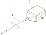
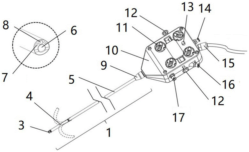
图1为一种支气管镜的外观示意图;Fig. 1 is a schematic diagram of the appearance of a bronchoscope;
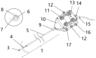
图2为一种支气管镜的结构示意图;;Figure 2 is a schematic structural view of a bronchoscope;
图3为头端部的结构示意图;Fig. 3 is a structural schematic diagram of the head end;
图4至图7为弯曲部结构及位姿检测部件的布局示意图;4 to 7 are schematic layout diagrams of the structure of the bending part and the pose detection components;
图8为插入管的弯曲部调弯示意及内部线路布置的示意图;Fig. 8 is a schematic diagram of the bending adjustment of the bending part of the insertion tube and a schematic diagram of the internal circuit layout;
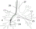
图9为支气管镜实时定位的示意图;Fig. 9 is a schematic diagram of bronchoscope real-time positioning;
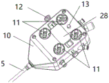
图10为调弯器械盒的传动卡爪一侧外观示意图;Fig. 10 is a schematic diagram of the appearance of one side of the transmission claw of the bending instrument box;
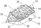
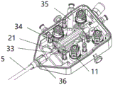
图11和图12为调弯器械盒的内部结构示意图;Figure 11 and Figure 12 are schematic diagrams of the internal structure of the bending instrument box;
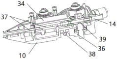
图13为调弯器械盒的竖向剖面图;Fig. 13 is a vertical sectional view of the bending instrument box;
图14为调弯器械盒的水平剖面图;Figure 14 is a horizontal sectional view of the bending instrument box;
图15为解锁组件的结构示意图;Figure 15 is a schematic structural view of the unlocking assembly;
图16为控弯部件处的竖向剖面图;Fig. 16 is a vertical sectional view at the bending control part;
图17为控弯部件的结构示意图;Fig. 17 is a structural schematic diagram of a bending control component;
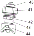
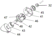
图18为控弯部件的爆炸图;Figure 18 is an exploded view of the bending control part;
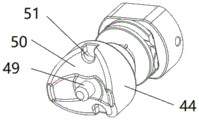
图19为传动卡爪的结构示意图;Figure 19 is a schematic structural view of the transmission claw;
图20为内部通道和器械通道闭合开关的结构示意图;Fig. 20 is a schematic structural view of the closing switch of the internal channel and the instrument channel;
图21为内部通道和器械通道闭合开关的剖面示意图;Fig. 21 is a schematic cross-sectional view of the closing switch of the internal channel and the instrument channel;
图22为器械通道闭合开关的部分结构示意图;Fig. 22 is a partial structural schematic diagram of an instrument channel closing switch;
图23为一种外部动力端的结构示意图;Fig. 23 is a schematic structural diagram of an external power end;
图24为一种外部动力端卡盘的结构示意图;Fig. 24 is a schematic structural view of an external power end chuck;
图25为一种外部锁扣卡爪和锁扣位锁定时的示意图。Fig. 25 is a schematic diagram of an external lock claw and lock position locked.
附图标记说明:Explanation of reference signs:
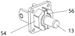
1:插入管;2:调弯器械盒;3:头端部;4:弯曲部;5:主软管;6:插入管器械通道;7:照明部件;8:摄像部件;9:保护套;10:安装座;11:控弯部件;12:解锁按钮;13:阀芯推杆;14:入口接头;15:航空插头;16:吸引阀接口;17:测漏接口;18:蛇骨结构;19:5DOF传感器;20:6DOF传感器;21:调弯丝;22:(四个5DOF传感器的)线缆;23:活检器械;24:病灶位置;25:人体定位传感器;26:支气管镜;27:人体气管及分支结构;28:锁扣盖板;29:立柱支撑板;30:密封圈;31:支撑立柱;32:轴端螺栓;33:钳道管;34:保持架;35:吸引注射通道;36:O型圈;37:器械通道;38:锁扣拉簧;39:软管;40:锁扣推杆;41:限位套;42:调弯丝转盘;43:定位端轴承;44:传动卡爪;45:支撑端轴承;46:张紧螺栓;47:定位槽;48:连接轴;49:定位轴;50:导向弧面;51:限位卡槽;52:调弯丝导向槽;53:钳道管通道口;54:阀体;55:三通连接件;56:定位划片;1: Insertion tube; 2: Bending instrument box; 3: Head end; 4: Curved part; 5: Main hose; 6: Insertion tube instrument channel; 7: Lighting component; 8: Camera component; 9: Protective cover ;10: Mounting seat; 11: Bending control part; 12: Unlock button; 13: Spool push rod; 14: Inlet joint; 15: Aviation plug; 16: Suction valve interface; 17: Leak detection interface; 18: Snake bone Structure; 19: 5DOF sensor; 20: 6DOF sensor; 21: Bending wire; 22: Cable (of four 5DOF sensors); 23: Biopsy instrument; 24: Lesion location; 25: Body positioning sensor; 26: Bronchoscope ;27: Human trachea and branch structure; 28: Lock cover plate; 29: Column support plate; 30: Seal ring; 31: Support column; 32: Shaft end bolt; 33: Clamp tube; 34: Cage; 35 : suction injection channel; 36: O-ring; 37: instrument channel; 38: lock spring; 39: hose; 40: lock push rod; 41: limit sleeve; 42: adjusting wire turntable; 43: Positioning end bearing; 44: transmission claw; 45: support end bearing; 46: tension bolt; 47: positioning slot; 48: connecting shaft; 49: positioning shaft; 50: guide arc surface; 51: limit card slot; 52: Bending wire guide groove; 53: Clamp pipe channel opening; 54: Valve body; 55: Tee connector; 56: Positioning scribe;
57:动力端安装座;58:动力端卡盘;59:锁扣卡爪;60:动力端推杆;61:中心定位轴孔;62:定位凸台。57: Power end mounting seat; 58: Power end chuck; 59: Lock claw; 60: Power end push rod; 61: Center positioning shaft hole; 62: Positioning boss.
具体实施方式Detailed ways
为了更清楚地说明本发明实施例或现有技术中的技术方案,下面将对照附图说明本发明的具体实施方式。显而易见地,下面描述中的附图仅仅是本发明的一些实施例,对于本领域普通技术人员来讲,在不付出创造性劳动的前提下,还可以根据这些附图获得其他的附图,并获得其他的实施方式。In order to more clearly illustrate the embodiments of the present invention or the technical solutions in the prior art, the specific implementation manners of the present invention will be described below with reference to the accompanying drawings. Obviously, the accompanying drawings in the following description are only some embodiments of the present invention, and those skilled in the art can obtain other accompanying drawings based on these drawings and obtain other implementations.
为使图面简洁,各图中只示意性地表示出了与本发明相关的部分,它们并不代表其作为产品的实际结构。另外,以使图面简洁便于理解,在有些图中具有相同结构或功能的部件,仅示意性地绘示了其中的一个,或仅标出了其中的一个。在本文中,“一个”不仅表示“仅此一个”,也可以表示“多于一个”的情形。In order to make the drawing concise, each drawing only schematically shows the parts related to the present invention, and they do not represent the actual structure of the product. In addition, to make the drawings concise and easy to understand, in some drawings, only one of the components having the same structure or function is schematically shown, or only one of them is marked. Herein, "a" not only means "only one", but also means "more than one".
本发明应用于经自然腔道的支气管镜活检手术,通过控制支气管镜26末端弯曲进入复杂的气道定位病灶位置24,完成活检手术。The present invention is applied to the bronchoscopic biopsy operation through the natural cavity, and the biopsy operation is completed by controlling the end of the
参看图1至图21,本实施例提供一种支气管镜26,包括插入管1和调弯器械盒2。插入管1内设有钳道管33和用于控制插入管1的弯曲部4调弯角度的多根调弯丝21,调弯器械盒2包括安装座10和多个控弯部件11。Referring to FIGS. 1 to 21 , this embodiment provides a
安装座10内设有安装腔,安装腔内设有内部通道,安装座10上设有连通外界和安装腔的安装通道,插入管1的近端安装于安装通道内且钳道管33的近端与内部通道的一端对接,钳道管33和内部通道形成器械通道37,内部通道的另一端穿设安装座10并于安装座10外形成器械通道37的入口。Mounting
多个控弯部件11与多根调弯丝21一一对应。控弯部件11安装于安装腔内且与安装座10转动连接,调弯丝21的近端绕设对应控弯部件11后与其固定连接。控弯部件11的输出端为传动卡爪44,传动卡爪44伸出安装腔位于安装座10外,传动卡爪44用于与外部动力端卡盘对接,由外部动力端卡盘驱动实现转动以控制对应调弯丝21的收放。A plurality of bending
现对本实施例的结构进行说明。为便于说明,下文中将靠近手术操作者的一端称为近端或后端,将远离手术操作者的一端称为远端或前端。The structure of this embodiment will now be described. For ease of description, the end close to the operator is referred to as the proximal end or rear end, and the end farther away from the operator is referred to as the distal end or front end.
图1和图2展示了支气管镜26的外观。支气管镜26包括前端的插入管1和后端的调弯器械盒2,插入管1和调弯器械盒2的连接处(此处具体指调弯器械盒2的外侧)设有软胶材质的保护套9对其进行保护。插入管1包括顺序连接的主软管5、弯曲部4和头端部3,头端部3的远端设有照明部件7和摄像部件8,照明部件7用于照亮前方区域,摄像部件8用于前方区域的图像采集。1 and 2 illustrate the appearance of the
头端部3和弯曲部4的近端分别设有位姿检测部件,用于分别检测所在位置处插入管1的姿态并输出,以经外界处理设备处理后模拟得到弯曲部4的实际轮廓,实现弯曲部4调弯的闭环控制;或,头端部3设有位姿检测部件,用于检测所在位置处插入管1的姿态并输出,以经外界处理设备处理后得到插入管1远端的位置及方向信息,实现弯曲部4调弯的开环控制。The proximal ends of the
插入管1上还有与照明部件7、摄像部件8和位姿检测部件互不干涉的插入管器械通道6。Also on the
手术前通过位置标定获取位姿检测部件与位于插入管1远端的插入管器械通道6口轴线的相对位置关系,并应用在手术算法程序中;在手术时,支气管镜26进入病人气道,位姿检测部件可实时反馈自身位置信息并通过相关算法程序显示出支气管内窥镜的位置,这样手术操作者可直观看到支气管内窥镜在病人肺部的实时位置并结合CT图像快速精确定位病灶,进行活检取样等手术。The relative positional relationship between the pose detection component and the axis of the insertion
具体,插入管器械通道6也称钳道,作为活检器械23的工作通道。插入管器械通道6依次穿设主软管5、弯曲部4和头端部3,插入管1上插入管器械通道6周侧的部分为插入管1的管壁部分,照明部件7、摄像部件8、位姿检测部件以及连接位姿检测部件的线缆均设于管壁部分内。Specifically, the insertion
插入管器械通道6的轴线与插入管1的轴线重合或平行。优选在本实施例中,参看图3,插入管器械通道6的轴线与插入管1的轴线平行,也就是在插入管1上偏心设置。在头端部3的远端端面,摄像部件8的中心和插入管器械通道6的中心位于经过头端部3的远端端面中心的直线上。照明部件7设有两个,两个照明部件7沿插入管1的周向设于摄像部件8的两侧。照明部件7可选用LED冷光源,摄像部件8可选用CMOS镜头。在其他实施例中,照明部件7和摄像部件8的数量和位置等,均可根据实际情况进行选择,对此不作具体限制。The axis of the insertion
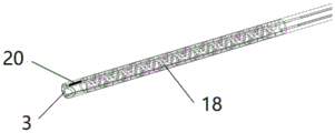
主要参看图4,弯曲部4可采用蛇骨结构18,头端部3和蛇骨根部分别布置位姿检测部件,具体对应图4,位姿检测部件为传感器组件,每组传感器组件包括两个5DOF传感器19,同组中的两个5DOF传感器19绕插入管1轴线对称布置,也就是沿圆周方向对角布置。前端的第一组5DOF传感器19可实时反馈头端部3的位置及方向,后端的第二组5DOF传感器19反馈位置及方向并作为基准参考,两组5DOF传感器19反馈数据组合可模拟出整个弯曲部4的实际轮廓,实现调弯过程的闭环控制。且,安装5DOF传感器19后可保证插入管1外径最小达3.6mm,从而达到更高的手术水准。Referring mainly to Fig. 4, the
当然,在其他实施例中,位姿检测部件的选用设备以及安装位置均可有其他选择,对此不作限制。例如,参看图5,在某一实施例中,位姿检测部件为6DOF传感器20,使用前后两个6DOF传感器20代替前后两组共4个5DOF传感器19的组合方式,可实现同样的功能(一个6DOF传感器20相当于2个对角布置的5DOF传感器19组合)。Certainly, in other embodiments, there may be other options for the selected equipment and the installation location of the pose detection component, which is not limited thereto. For example, referring to Fig. 5, in a certain embodiment, the pose detection component is a
例如,参看图6,在某一实施例中,只在头端部3的圆周方向对角布置两个5DOF传感器19,可反馈支气管镜26远端的位置及方向信息,以开环控制的方式辅助调弯。For example, referring to Fig. 6, in a certain embodiment, only two
例如,参看图7,在某一实施例中,只在头端部3布置一个6DOF传感器20,可反馈支气管镜26远端的位置及方向信息,以开环控制的方式辅助调弯。而在另外的实施例中,位姿检测部件也可以采用光纤形状传感器(光纤形状传感器也可以实现支气管内窥镜的位姿反馈)等,因此,对于位姿检测部件中传感器的种类、多种组合及布置方式、圆周方向上是否均布、与调弯丝21或镜头的夹角大小等,都不作限制。For example, referring to FIG. 7 , in a certain embodiment, only one
请主要参看图8,插入管1的管壁部分内沿周向均布有四根调弯丝21(一般采用钢丝),调弯丝21单独牵引可实现180度的弯曲,四根调弯丝21配合可实现空间内任意方向的180度弯曲,四个5DOF传感器19的线缆22设置在插入管1内壁部分内,然后连接到调弯器械盒2,再连接到外界处理设备。Please mainly refer to Fig. 8, there are four bending wires 21 (generally steel wires) evenly distributed along the circumference in the wall part of the
图9展示了某一手术中的状态。将病人肺部安置在固定磁场内,在人体外表贴附3个人体定位传感器25,用于定位人体气管及分支结构27,手术时支气管镜26从病人口腔穿入气道,在位姿检测部件的定位下可清晰观察到支气管镜26的弯曲部4在气道内的实时位置,结合CT图像控制支气管镜26的头端部3到达病灶位置24,再控制活检器械23进入,当头端部3上的CMOS镜头观察到活检器械23刚好到达远端时,可再次确认头端部3远端位置是否对准病灶,然后进行活检取样,避免了因活检器械23进出等振动造成的活检偏位,进而提高了活检成功率。Figure 9 shows the state of an operation. The patient's lungs are placed in a fixed magnetic field, and three human
以上部分展示了几种插入管1的结构,但本发明中的插入管1不限于以上展示的几种插入管1。The above part shows several structures of the
调弯器械盒2包含安装座10以及设置在安装座10上的控弯部件11、解锁组件、(器械通道37的)入口接头14、阀芯推杆13、吸引阀接口16、测漏接口17、(用于线缆的导出)航空插头15等组成,设计为一种有限次重复灭菌使用的密封型调弯机构。The bending
插入管1内的四根调弯丝21的远端均布于插入管1对应位置处的周向,安装座10上设有四个控弯部件11,内部通道的两侧分别设有两个控弯部件11。位于内部通道同一侧的两个控弯部件11沿内部通道的轴向布置,且位于内部通道两侧的控弯部件11对称设置。当然在其他实施例中,调弯丝21和控弯部件11的数量和位置不作限制。The distal ends of the four
在本实施例中,四根调节丝21环向均布,相互配合使用,可实现支气管镜26远端的空间360度调弯效果。具体为:四根调节丝21均布在圆周方向,可假设为0°、90°、180°、270°,单根调节丝21拉紧可控制弯曲部4沿对应方向打弯(其余三根调节丝21配合进行相对合适的拉伸),当相邻两根调节丝21(例如0°和90°的)同时拉紧相同长度时,弯曲部4理论上会沿45°方向打弯(其余两根调节丝21配合进行相对合适的拉伸);当相邻两根调节丝21(例如0°和90°的)同时拉紧不同长度时,弯曲部4理论上会沿指定的某一方向打弯(其余两根调节丝21配合进行相对合适的拉伸),控制这两根调节丝21的拉伸量即可控制在0~90°范围内打弯,同理控制四根调节丝21的拉伸量即可控制弯曲部4在沿中心轴线的旋转范围内360°打弯。In this embodiment, the four adjusting
图10展示了调弯器械盒2对接外部动力端一侧的外形轮廓,主要部件为四套大锥度导向的控弯部件11,当弯曲部4处于自由状态时,控弯部件11会有角度可控的转动偏差(即控弯部件11允许相对安装座10转动),确保可以顺畅对接动力端,对接时动力端卡盘上的锁扣卡爪会与传动卡爪44咬合固定,解锁时两根手指同时按动左右两侧的(解锁组件中的)解锁按钮12即可轻松分离。Figure 10 shows the profile of the side of the bending
图11和图12展示了安装腔内部结构,主软管5包含钳道管33(内部管道即为组成插入管器械通道6的一部分)、四根调弯丝21、CMOS镜头及位姿检测部件的线缆、外层包皮等。保持架34安装在安装腔内,所有线路铰接在一起并沿着保持架34上的线路导槽到达线缆接口通道,由线缆接口通道伸出并焊接航空插头15(航空插头15位于安装座10外)与设备端对接。在保持架34的上方(图11和图12中的方位)设有立柱支撑板29,立柱支撑板29通过支撑立柱31固定安装于安装腔内。Figures 11 and 12 show the internal structure of the installation cavity. The
主要参看图16至图19,控弯部件11包括上述传动卡爪44和转盘组件。传动卡爪44上设有连接轴48,连接轴48穿设安装座10伸入安装腔内,且在穿设时与安装座10转动连接,进一步在转动连接处可设置定位端轴承43。Referring mainly to FIG. 16 to FIG. 19 , the bending
转盘组件设于安装腔内,且转盘组件固定连接于连接轴48。调弯丝21绕设于转盘组件且调弯丝21的近端固定连接在转盘组件上。具体,转盘组件包括调弯丝转盘42和限位套41。调弯丝转盘42上具有抱箍结构,抱箍结构通过紧固件(可选用张紧螺栓46)抱紧连接轴48实现与连接轴48的固定连接;当张紧螺栓46未使抱箍结构抱紧连接轴48时,抱箍结构可绕连接轴48转动。如此使得可微调调弯丝21松紧度,当调节结束后拧紧张紧螺栓46限制调弯丝转盘42相对连接轴48的转动自由度。The turntable assembly is disposed in the installation cavity, and the turntable assembly is fixedly connected to the connecting
限位套41套设于调弯丝转盘42上。调弯丝21的近端安装有定位球,调弯丝转盘42和限位套41上分别设有定位槽47,两者配合形成定位腔,定位球装配于定位腔内实现定位和固定,限位套41通过紧固件(可以选用紧定螺钉)固定在调弯丝转盘42上。具体,定位球上设有台阶型的内孔,调弯丝21采用钢丝,钢丝的末端先穿过定位球的内孔,之后在钢丝末端安装固定圆柱形铆钉,定位球可通过内孔在钢丝上滑动;在转盘组件上安装定位球时需要钢丝拉紧,定位球滑动到末端,而铆钉卡住定位球内孔上的台阶以阻止定位球脱出,然后定位球放入定位腔内,定位腔的形状限制定位球和铆钉的位置,起到固定钢丝末端的作用。其中,定位腔上会留有容钢丝通过的孔,该孔可设置在调弯丝转盘42的外圆弧面上。The
连接轴48伸入安装腔的一端的端面设有螺纹孔,螺纹孔内螺纹连接有轴端螺栓32。有支撑端轴承45安装在连接轴48上,内圈固定在连接轴48上并抵住调节丝转盘42,外圈固定在立柱支撑板29的轴承位上,并抵住轴端螺栓32的螺帽上。即轴端螺栓32旋紧时将支撑端轴承45压在调节丝转盘42上,轴端螺栓32上的螺帽配合调节丝转盘42限制支撑端轴承45的轴向移动。优选的,在螺帽和支撑端轴承45之间可设置垫片。The end surface of one end of the connecting
传动卡爪44上设有定位轴49,定位轴49的轴线与控弯部件11和安装座10的转动轴线重合,定位轴49用于对接外部动力端卡盘上的中心定位轴孔,用于保证对接精度。传动卡爪44上至少设有一个限位卡槽51,限位卡槽51用于对接外部动力端卡盘上的定位凸台,实现传动卡爪44和外部动力端卡盘的相对位置固定,以传递扭矩、使外部动力端卡盘转动时带动传动卡爪44转动。The
传动卡爪44上还设有与限位卡槽51对应的导向弧面50,限位卡槽51设于导向弧面50的导向末端位置。导向弧面50的表面高度向导向末端位置逐渐降低以使抵接于导向弧面50的物体在导向弧面50的引导滑动至导向末端位置。优选的,传动卡爪44上设有两组限位卡槽51和导向弧面50,且两组分别对称设于定位轴49的两侧。如图19所示,导向弧面50可以为锥形导向弧面。The
如此,在对接动力端卡盘时即使动力端卡盘和传动卡爪44有很大偏差错位,也可实现轻松自由对接(两端卡盘均设置转动极限位,对接允许偏差可覆盖有效行程),不用归零对接。In this way, even if there is a large deviation and misalignment between the power end chuck and the
安装座10上设有解锁组件,解锁组件用于解除当外部动力端卡盘和传动卡爪44的对接时安装有外部动力端卡盘的外部动力端安装座和安装座10的相对位置的锁定。具体,解锁组件包括锁扣盖板28和锁扣推杆40,锁扣盖板28连接在安装座10上,锁扣盖板28上设有锁扣位,用于动力端安装座上锁扣卡爪在预紧力作用下的锁定,当锁扣卡爪锁定在锁扣位上时动力端安装座和安装座10的相对位置锁定。锁扣推杆40滑动连接在安装座10上,锁扣推杆40在弹性件的作用下位于滑动行程的始端,锁扣推杆40在受到外力作用克服弹性件的弹性阻力移动至滑动行程末端的过程中,推动锁扣卡爪克服预紧力的作用离开锁扣位。The mounting
更具体的,参看图15和图25,安装座10上滑动连接有两个锁扣推杆40,两个锁扣推杆40的外侧端(相对安装座10而言的)均安装有解锁按钮12,方便手术操作者推动锁扣推杆40,弹性件可以是锁扣拉簧38,锁扣拉簧38将两个锁扣推杆40相向拉动达到滑动行程的始端。当需要解除安装座10和动力端安装座的相对位置的锁定时,手术操作者的两个手指按住两个解锁按钮12并向中间压缩,两个锁扣推杆40会克服锁扣拉簧38的拉力相向移动,从而使得锁扣推杆40未安装有锁扣弹簧的一端能够将动力端安装座上的锁扣卡爪从锁扣位上推开,从而使得动力端安装座和安装座10分离。More specifically, referring to Fig. 15 and Fig. 25, two
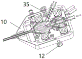
为实现医疗程序中的吸引注射功能,在安装座10上设置吸引注射通道35。吸引注射通道35的主体部分设置在安装腔内,吸引注射通道35的一端与内部通道连通,另一端位于安装座10外安装吸引阀接口16,用于对接吸引注射设备。具体,主要参看图20和21,内部通道包括三通连接件55和软管39,三通连接件55的三个通道口分别连通钳道管33近端、吸引注射通道35与内部通道连通的一端、软管39的一端,而软管39的另一端伸出安装座10并安装有入口接头14。也就是,在器械通道37上分离出一个支路,用作吸引注射通道35。参看图20,三通连接件55上还设有两个调弯丝导向槽52,用于与后端两个控弯部件11对应的两个调弯丝21的导向;三通连接件55上用于与钳道管33连通的通道口为钳道管通道口53。In order to realize the suction injection function in the medical procedure, a
内部通道上还设有器械通道闭合开关,用于封闭其所在位置处的内部通道;器械通道闭合开关设于内部通道上且设于吸引注射通道35和器械通道37的入口之间。具体,器械通道闭合开关包括阀体54和阀芯推杆13,软管39穿过阀体54上的软管通道,软管通道的侧向开有推杆口,阀芯推杆13滑动连接于阀体54上,且阀芯推杆13的一端可通过推杆口伸入软管通道并将软管39压紧使得软管39内通道闭合;阀芯推杆13的另一端设于安装座10外。当活检器械23正常通过时,阀芯推杆13不动作,使软管39内通道保持连通状态,定位划片56安装在阀芯推杆13上,一方面限制阀芯推杆13周向转动,另一方面起到移动导向的作用。当需要吸引注射时,由外部动力端推杆驱动阀芯推杆13向软管39方向推进,使软管39内通道闭合。The internal channel is also provided with an instrument channel closing switch for closing the internal channel at its location; the instrument channel closing switch is arranged on the internal channel and between the entrance of the
安装座10上设有多个连通安装腔且其内安装有构件的安装座开口(如用于控弯部件11穿设的开口、安装通道、锁扣推杆40处的开口等),安装座开口和其内的构件之间设有密封结构,用于实现开口和构件的密封连接,以防止支气管镜26在清洗灭菌时液体进入安装腔,从而使得支气管镜26能够有限次重复灭菌使用。密封结构可以是O型圈36和密封圈30等。如:图12所示的主软管5和安装通道之间的O型圈36;安装座10由两部分扣合组成,两部分在连接时需设置密封圈30;图13中所示的阀芯推杆13和安装座10之间的O型圈36;图16中所示的传动卡爪44和安装座10之间的O型圈36,等等。安装座10上所有的接头件均可设计为细牙螺纹安装,从而达到防水密封效果。Mounting
测漏接口17的作用是检测调弯器械盒2中安装腔的密封性,因为支气管镜26设计为一种可重复灭菌使用的密封型器械,每次清洗完成后需要外部检测设备与测漏接口17接通,用于检测密封是否良好。测漏接口17和吸引阀接口16、入口接头14的安装方式一样,其主体的细牙外螺纹旋在安装座10的侧壁上,使与安装腔连通。The function of the
调弯器械盒2中的主要功能包括四个控弯部件11实现弯曲部4的万向调节功能,其具体的实现方式及细节在其他实施例中可进行变换调整。比如:调节丝转盘42上不设置抱箍结构,和连接轴48之间通过键销等方式进行定位紧固,而调节丝21的末端采用调节螺钉,调节丝21末端伸出调节螺钉的长度可调;解锁组件的弹性件采用锁扣拉簧38将两个锁扣推杆40在不加外力作用下移动至滑动行程始端的结构可替换成弹性件采用压缩弹簧或扭簧的结构等。The main functions in the bending
上面结合附图对本发明的实施方式作了详细说明,但是本发明并不限于上述实施方式。即使对本发明作出各种变化,倘若这些变化属于本发明权利要求及其等同技术的范围之内,则仍落入在本发明的保护范围之中。The embodiments of the present invention have been described in detail above with reference to the accompanying drawings, but the present invention is not limited to the above embodiments. Even if various changes are made to the present invention, if these changes fall within the scope of the claims of the present invention and equivalent technologies, they still fall within the protection scope of the present invention.
Claims (14)
Priority Applications (1)
| Application Number | Priority Date | Filing Date | Title |
|---|---|---|---|
| CN202310386365.1A CN116327101A (en) | 2023-04-12 | 2023-04-12 | a bronchoscope |
Applications Claiming Priority (1)
| Application Number | Priority Date | Filing Date | Title |
|---|---|---|---|
| CN202310386365.1A CN116327101A (en) | 2023-04-12 | 2023-04-12 | a bronchoscope |
Publications (1)
| Publication Number | Publication Date |
|---|---|
| CN116327101A true CN116327101A (en) | 2023-06-27 |
Family
ID=86885734
Family Applications (1)
| Application Number | Title | Priority Date | Filing Date |
|---|---|---|---|
| CN202310386365.1A Pending CN116327101A (en) | 2023-04-12 | 2023-04-12 | a bronchoscope |
Country Status (1)
| Country | Link |
|---|---|
| CN (1) | CN116327101A (en) |
Citations (8)
| Publication number | Priority date | Publication date | Assignee | Title |
|---|---|---|---|---|
| CN1794944A (en) * | 2003-04-01 | 2006-06-28 | 波士顿科技有限公司 | Single use endoscopic imaging system |
| CN101795616A (en) * | 2007-09-11 | 2010-08-04 | 奥林巴斯株式会社 | Endoscope device |
| CN103717147A (en) * | 2011-05-27 | 2014-04-09 | 伊西康内外科公司 | Robotically-controlled endoscopic accessory channel |
| CN109953736A (en) * | 2019-05-06 | 2019-07-02 | 南京法迈特科技发展有限公司 | Disposable full throwing formula endoscope |
| CN209259409U (en) * | 2019-01-03 | 2019-08-16 | 深圳大学 | Automatic winding apparatus is used in a kind of production of amorphous alloy wire |
| CN213335739U (en) * | 2020-09-28 | 2021-06-01 | 江苏鼎翔节能科技有限公司 | Anti-loosening finned tube |
| CN114305295A (en) * | 2020-09-28 | 2022-04-12 | 微创优通医疗科技(嘉兴)有限公司 | Endoscope and endoscope system |
| CN217592823U (en) * | 2022-03-17 | 2022-10-18 | 微创优通医疗科技(嘉兴)有限公司 | Handle bending control locking mechanism, endoscope handle and endoscope system |
-
2023
- 2023-04-12 CN CN202310386365.1A patent/CN116327101A/en active Pending
Patent Citations (8)
| Publication number | Priority date | Publication date | Assignee | Title |
|---|---|---|---|---|
| CN1794944A (en) * | 2003-04-01 | 2006-06-28 | 波士顿科技有限公司 | Single use endoscopic imaging system |
| CN101795616A (en) * | 2007-09-11 | 2010-08-04 | 奥林巴斯株式会社 | Endoscope device |
| CN103717147A (en) * | 2011-05-27 | 2014-04-09 | 伊西康内外科公司 | Robotically-controlled endoscopic accessory channel |
| CN209259409U (en) * | 2019-01-03 | 2019-08-16 | 深圳大学 | Automatic winding apparatus is used in a kind of production of amorphous alloy wire |
| CN109953736A (en) * | 2019-05-06 | 2019-07-02 | 南京法迈特科技发展有限公司 | Disposable full throwing formula endoscope |
| CN213335739U (en) * | 2020-09-28 | 2021-06-01 | 江苏鼎翔节能科技有限公司 | Anti-loosening finned tube |
| CN114305295A (en) * | 2020-09-28 | 2022-04-12 | 微创优通医疗科技(嘉兴)有限公司 | Endoscope and endoscope system |
| CN217592823U (en) * | 2022-03-17 | 2022-10-18 | 微创优通医疗科技(嘉兴)有限公司 | Handle bending control locking mechanism, endoscope handle and endoscope system |
Similar Documents
| Publication | Publication Date | Title |
|---|---|---|
| US8690755B2 (en) | Endoscopic positioning system | |
| JP4398184B2 (en) | Endoscope | |
| US11826022B2 (en) | Endoscope having separable probe | |
| US11696673B2 (en) | Enhanced flexible robotic endoscopy apparatus | |
| US8262677B2 (en) | Ligation tool for endoscope and endoscopic ligation system | |
| CN115715702B (en) | Flexible endoscope operation robot system | |
| US20200297189A1 (en) | Endoscope | |
| EP3626154A1 (en) | Modular endoscope | |
| CN111770715A (en) | Probe device combined with endoscope in a removable manner | |
| US11324394B2 (en) | Endoscope | |
| CN105188506B (en) | Device for endoscopic surgery | |
| WO2012132778A1 (en) | Endoscope insertion assitive device | |
| US20200405143A1 (en) | Laparoscopic insertion tool | |
| CN215128274U (en) | Steering control mechanism, endoscope, and medical examination device | |
| CN115444574B (en) | Flexible instrument driving device, flexible instrument and surgical robot | |
| CN116327101A (en) | a bronchoscope | |
| US20110288371A1 (en) | Endoscope device | |
| CN116327102A (en) | A positionable and navigable electronic bronchoscope and its insertion tube | |
| CN218832879U (en) | Soft endoscope operation device | |
| WO2021097617A1 (en) | Endoscope structure | |
| US20230011670A1 (en) | Rapid exchange endoscope system | |
| JP2840008B2 (en) | Connecting device in endoscope | |
| CN219021531U (en) | Auxiliary robot for digestive endoscopy treatment | |
| CN223473714U (en) | Endoscope guiding device | |
| EP3082563B1 (en) | An enhanced flexible robotic endoscopy apparatus |
Legal Events
| Date | Code | Title | Description |
|---|---|---|---|
| PB01 | Publication | ||
| PB01 | Publication | ||
| SE01 | Entry into force of request for substantive examination | ||
| SE01 | Entry into force of request for substantive examination |