CN112472006B - Endoscope with chain locking prevention function - Google Patents
Endoscope with chain locking prevention function Download PDFInfo
- Publication number
- CN112472006B CN112472006B CN202010914780.6A CN202010914780A CN112472006B CN 112472006 B CN112472006 B CN 112472006B CN 202010914780 A CN202010914780 A CN 202010914780A CN 112472006 B CN112472006 B CN 112472006B
- Authority
- CN
- China
- Prior art keywords
- chain
- connection block
- connection
- block
- coil spring
- Prior art date
- Legal status (The legal status is an assumption and is not a legal conclusion. Google has not performed a legal analysis and makes no representation as to the accuracy of the status listed.)
- Active
Links
- 230000002265 prevention Effects 0.000 title claims description 19
- 238000006243 chemical reaction Methods 0.000 claims abstract description 23
- 238000003780 insertion Methods 0.000 claims description 55
- 230000037431 insertion Effects 0.000 claims description 55
- 238000010168 coupling process Methods 0.000 claims description 19
- 238000005859 coupling reaction Methods 0.000 claims description 19
- 230000008878 coupling Effects 0.000 claims description 18
- 239000002184 metal Substances 0.000 claims description 13
- 238000005286 illumination Methods 0.000 claims description 3
- 238000005452 bending Methods 0.000 description 9
- 238000001356 surgical procedure Methods 0.000 description 4
- 238000002674 endoscopic surgery Methods 0.000 description 3
- 238000003384 imaging method Methods 0.000 description 3
- 230000001965 increasing effect Effects 0.000 description 3
- 238000010586 diagram Methods 0.000 description 2
- 230000000740 bleeding effect Effects 0.000 description 1
- 230000007423 decrease Effects 0.000 description 1
- 230000003247 decreasing effect Effects 0.000 description 1
- 230000000694 effects Effects 0.000 description 1
- 238000005516 engineering process Methods 0.000 description 1
- 230000002708 enhancing effect Effects 0.000 description 1
- 238000002357 laparoscopic surgery Methods 0.000 description 1
- 239000000463 material Substances 0.000 description 1
- 238000012986 modification Methods 0.000 description 1
- 230000004048 modification Effects 0.000 description 1
- 230000000149 penetrating effect Effects 0.000 description 1
- 231100000241 scar Toxicity 0.000 description 1
- 238000000926 separation method Methods 0.000 description 1
- 238000006467 substitution reaction Methods 0.000 description 1
- 238000004804 winding Methods 0.000 description 1
Images




Classifications
-
- A—HUMAN NECESSITIES
- A61—MEDICAL OR VETERINARY SCIENCE; HYGIENE
- A61B—DIAGNOSIS; SURGERY; IDENTIFICATION
- A61B1/00—Instruments for performing medical examinations of the interior of cavities or tubes of the body by visual or photographical inspection, e.g. endoscopes; Illuminating arrangements therefor
- A61B1/005—Flexible endoscopes
- A61B1/0051—Flexible endoscopes with controlled bending of insertion part
- A61B1/0052—Constructional details of control elements, e.g. handles
-
- A—HUMAN NECESSITIES
- A61—MEDICAL OR VETERINARY SCIENCE; HYGIENE
- A61B—DIAGNOSIS; SURGERY; IDENTIFICATION
- A61B1/00—Instruments for performing medical examinations of the interior of cavities or tubes of the body by visual or photographical inspection, e.g. endoscopes; Illuminating arrangements therefor
- A61B1/00002—Operational features of endoscopes
-
- A—HUMAN NECESSITIES
- A61—MEDICAL OR VETERINARY SCIENCE; HYGIENE
- A61B—DIAGNOSIS; SURGERY; IDENTIFICATION
- A61B1/00—Instruments for performing medical examinations of the interior of cavities or tubes of the body by visual or photographical inspection, e.g. endoscopes; Illuminating arrangements therefor
- A61B1/00064—Constructional details of the endoscope body
- A61B1/00066—Proximal part of endoscope body, e.g. handles
-
- A—HUMAN NECESSITIES
- A61—MEDICAL OR VETERINARY SCIENCE; HYGIENE
- A61B—DIAGNOSIS; SURGERY; IDENTIFICATION
- A61B1/00—Instruments for performing medical examinations of the interior of cavities or tubes of the body by visual or photographical inspection, e.g. endoscopes; Illuminating arrangements therefor
- A61B1/00064—Constructional details of the endoscope body
- A61B1/00071—Insertion part of the endoscope body
-
- A—HUMAN NECESSITIES
- A61—MEDICAL OR VETERINARY SCIENCE; HYGIENE
- A61B—DIAGNOSIS; SURGERY; IDENTIFICATION
- A61B1/00—Instruments for performing medical examinations of the interior of cavities or tubes of the body by visual or photographical inspection, e.g. endoscopes; Illuminating arrangements therefor
- A61B1/00064—Constructional details of the endoscope body
- A61B1/00071—Insertion part of the endoscope body
- A61B1/0008—Insertion part of the endoscope body characterised by distal tip features
- A61B1/00101—Insertion part of the endoscope body characterised by distal tip features the distal tip features being detachable
-
- A—HUMAN NECESSITIES
- A61—MEDICAL OR VETERINARY SCIENCE; HYGIENE
- A61B—DIAGNOSIS; SURGERY; IDENTIFICATION
- A61B1/00—Instruments for performing medical examinations of the interior of cavities or tubes of the body by visual or photographical inspection, e.g. endoscopes; Illuminating arrangements therefor
- A61B1/00064—Constructional details of the endoscope body
- A61B1/00105—Constructional details of the endoscope body characterised by modular construction
-
- A—HUMAN NECESSITIES
- A61—MEDICAL OR VETERINARY SCIENCE; HYGIENE
- A61B—DIAGNOSIS; SURGERY; IDENTIFICATION
- A61B1/00—Instruments for performing medical examinations of the interior of cavities or tubes of the body by visual or photographical inspection, e.g. endoscopes; Illuminating arrangements therefor
- A61B1/00112—Connection or coupling means
-
- A—HUMAN NECESSITIES
- A61—MEDICAL OR VETERINARY SCIENCE; HYGIENE
- A61B—DIAGNOSIS; SURGERY; IDENTIFICATION
- A61B1/00—Instruments for performing medical examinations of the interior of cavities or tubes of the body by visual or photographical inspection, e.g. endoscopes; Illuminating arrangements therefor
- A61B1/00112—Connection or coupling means
- A61B1/00121—Connectors, fasteners and adapters, e.g. on the endoscope handle
- A61B1/00128—Connectors, fasteners and adapters, e.g. on the endoscope handle mechanical, e.g. for tubes or pipes
-
- A—HUMAN NECESSITIES
- A61—MEDICAL OR VETERINARY SCIENCE; HYGIENE
- A61B—DIAGNOSIS; SURGERY; IDENTIFICATION
- A61B1/00—Instruments for performing medical examinations of the interior of cavities or tubes of the body by visual or photographical inspection, e.g. endoscopes; Illuminating arrangements therefor
- A61B1/005—Flexible endoscopes
- A61B1/0051—Flexible endoscopes with controlled bending of insertion part
-
- A—HUMAN NECESSITIES
- A61—MEDICAL OR VETERINARY SCIENCE; HYGIENE
- A61B—DIAGNOSIS; SURGERY; IDENTIFICATION
- A61B1/00—Instruments for performing medical examinations of the interior of cavities or tubes of the body by visual or photographical inspection, e.g. endoscopes; Illuminating arrangements therefor
- A61B1/005—Flexible endoscopes
- A61B1/0051—Flexible endoscopes with controlled bending of insertion part
- A61B1/0055—Constructional details of insertion parts, e.g. vertebral elements
-
- A—HUMAN NECESSITIES
- A61—MEDICAL OR VETERINARY SCIENCE; HYGIENE
- A61B—DIAGNOSIS; SURGERY; IDENTIFICATION
- A61B1/00—Instruments for performing medical examinations of the interior of cavities or tubes of the body by visual or photographical inspection, e.g. endoscopes; Illuminating arrangements therefor
- A61B1/005—Flexible endoscopes
- A61B1/0051—Flexible endoscopes with controlled bending of insertion part
- A61B1/0057—Constructional details of force transmission elements, e.g. control wires
-
- A—HUMAN NECESSITIES
- A61—MEDICAL OR VETERINARY SCIENCE; HYGIENE
- A61B—DIAGNOSIS; SURGERY; IDENTIFICATION
- A61B1/00—Instruments for performing medical examinations of the interior of cavities or tubes of the body by visual or photographical inspection, e.g. endoscopes; Illuminating arrangements therefor
- A61B1/04—Instruments for performing medical examinations of the interior of cavities or tubes of the body by visual or photographical inspection, e.g. endoscopes; Illuminating arrangements therefor combined with photographic or television appliances
- A61B1/05—Instruments for performing medical examinations of the interior of cavities or tubes of the body by visual or photographical inspection, e.g. endoscopes; Illuminating arrangements therefor combined with photographic or television appliances characterised by the image sensor, e.g. camera, being in the distal end portion
- A61B1/053—Instruments for performing medical examinations of the interior of cavities or tubes of the body by visual or photographical inspection, e.g. endoscopes; Illuminating arrangements therefor combined with photographic or television appliances characterised by the image sensor, e.g. camera, being in the distal end portion being detachable
-
- A—HUMAN NECESSITIES
- A61—MEDICAL OR VETERINARY SCIENCE; HYGIENE
- A61B—DIAGNOSIS; SURGERY; IDENTIFICATION
- A61B1/00—Instruments for performing medical examinations of the interior of cavities or tubes of the body by visual or photographical inspection, e.g. endoscopes; Illuminating arrangements therefor
- A61B1/06—Instruments for performing medical examinations of the interior of cavities or tubes of the body by visual or photographical inspection, e.g. endoscopes; Illuminating arrangements therefor with illuminating arrangements
- A61B1/0661—Endoscope light sources
- A61B1/0669—Endoscope light sources at proximal end of an endoscope
-
- A—HUMAN NECESSITIES
- A61—MEDICAL OR VETERINARY SCIENCE; HYGIENE
- A61B—DIAGNOSIS; SURGERY; IDENTIFICATION
- A61B1/00—Instruments for performing medical examinations of the interior of cavities or tubes of the body by visual or photographical inspection, e.g. endoscopes; Illuminating arrangements therefor
- A61B1/313—Instruments for performing medical examinations of the interior of cavities or tubes of the body by visual or photographical inspection, e.g. endoscopes; Illuminating arrangements therefor for introducing through surgical openings, e.g. laparoscopes
-
- A—HUMAN NECESSITIES
- A61—MEDICAL OR VETERINARY SCIENCE; HYGIENE
- A61B—DIAGNOSIS; SURGERY; IDENTIFICATION
- A61B2560/00—Constructional details of operational features of apparatus; Accessories for medical measuring apparatus
- A61B2560/04—Constructional details of apparatus
Landscapes
- Health & Medical Sciences (AREA)
- Life Sciences & Earth Sciences (AREA)
- Surgery (AREA)
- Engineering & Computer Science (AREA)
- Biomedical Technology (AREA)
- Molecular Biology (AREA)
- Pathology (AREA)
- Radiology & Medical Imaging (AREA)
- Nuclear Medicine, Radiotherapy & Molecular Imaging (AREA)
- Biophysics (AREA)
- Physics & Mathematics (AREA)
- Heart & Thoracic Surgery (AREA)
- Medical Informatics (AREA)
- Optics & Photonics (AREA)
- Animal Behavior & Ethology (AREA)
- General Health & Medical Sciences (AREA)
- Public Health (AREA)
- Veterinary Medicine (AREA)
- Mechanical Engineering (AREA)
- Endoscopes (AREA)
- Instruments For Viewing The Inside Of Hollow Bodies (AREA)
Abstract
The invention provides an endoscope. The present invention includes a direction conversion module for converting rotational movement of the upper sprocket and the lower sprocket into linear movement of the upper chain and the lower chain by maintaining a linear state of the upper chain and the lower chain which are pulled and pushed when the operation unit rotates, wherein the direction conversion module includes first and second connection blocks, third and fourth connection blocks, a first guide rail of a predetermined length, a second guide rail of a predetermined length, first and second coil springs, and third and fourth coil springs.
Description
Technical Field
The present invention relates to an endoscope, and more particularly, to an endoscope having a chain locking prevention function, in which when an operation portion, in which the distal end of an insertion portion is bent in the up-down direction and the left-right direction, is rotated, the length is wound around a sprocket, and thereby the parallel state of a chain, in which both ends are reciprocally moved in opposite directions, is maintained stably in a straight line at all times, to prevent locking, and thus, rotation can be performed precisely and smoothly.
Background
In general, in an operation using an endoscope, after an endoscope provided with a camera and an operation tool are inserted through a small hole, an affected part of a patient is observed by an image captured by the endoscope in the body and the operation is performed, instead of cutting a human body in a large range.
In particular, since the incision site of the endoscopic surgery performed from the beginning of the laparoscopic surgery is small compared to the open surgery, the scar site is also small, and the amount of bleeding is also small, so that the patient can recover more quickly after the completion of the surgery.
Recently, technology has been developed such that endoscopic surgery can be performed for almost all the surgeries for which open surgery is required, and furthermore, the application of endoscopic surgery to other medical fields has been increasing.
In a conventional general endoscope, an insertion portion to be inserted into a human body and an operation portion to control the insertion portion are integrally formed, and a plurality of pipes and guides penetrating the inside of each portion are built in, and in particular, an imaging device such as a high-priced CCD is provided at the tip of the insertion portion to be inserted into the human body, so that it is difficult to separate the insertion portion from the operation portion only to perform alternation.
(patent document 1) KR10-0673412B1
(patent document 2) KR10-1091999B1
(patent document 3KR10-1783225B1
Patent documents 1 to 3 disclose detachable endoscopes of various forms which are used in connection with each other by combining an insertion portion to be inserted into the body and an operation portion to operate the insertion portion, or which are stored separately from each other, in accordance with a trend of enhancing a sanitary function of the medical endoscope.
In the endoscope disclosed in this patent document, in order to bend the distal end of the insertion portion in the up-down direction and the left-right direction, the direction is switched to the straight direction by a chain, and the chain is wound around a sprocket that rotates by rotation of a rotation handle, whereby a pair of wires are reciprocated in the straight direction by an external force transmitted through both ends of the chain, and one ends of the pair of wires are connected to the inside of the distal end of the insertion portion.
The front end of the insertion portion may be bent in the up-down direction or in the left-right direction by pulling or pushing the pair of wires formed as described above.
On the other hand, as shown in fig. 8, both ends of the chain 26 wound around the sprocket 25 of the rotary operating handles 29a, 29b are connected to the other wires 11, 12 of the insertion portion via the pair of wires 21, 22, respectively, and are arranged side by side, and the rotary operating handles 29a, 29b are provided on the operating portion 20 coupled to the insertion portion 10, whereby pulling and pushing of the chain 26 arranged side by side are performed simultaneously in opposite directions.
However, in the direction conversion section for converting the rotational movement of the sprocket 25 into the linear movement of the chain 26, when the speeds and distances of the chains pulled and pushed in opposite directions are different, the plurality of link members are linked to each other by the pin member in the chain 26, and therefore, the link connection portions between the plurality of link members are not aligned on a straight line but are curved portions that curve inward or outward.
In the course of the above-mentioned locking portion of the chain passing through the internal passage of the narrow direction switching section of the operation portion, noise is generated due to interference with other adjacent components, and because of the above-mentioned bending portion, it is difficult to precisely control the pulling amount or pushing amount of the chain due to the rotation amount of the rotating operation handle, and it is impossible to precisely perform the endoscope operation, on the other hand, in the case that the size of the above-mentioned bending portion becomes more than necessary, operation failure due to constriction is caused, and a fatal problem of losing the function of the endoscope is generated.
Disclosure of Invention
Accordingly, the present invention has been made to solve the above-mentioned problems, and an object of the present invention is to provide an endoscope having a chain locking prevention function, in which an external force such as an elastic supporting force is manually applied to a chain that reciprocates in opposite directions when an operation portion rotates, and thereby the linear state is stably maintained at all times so as to prevent bending or locking of the chain during the reciprocating movement by winding the chain around a sprocket in the middle of the length thereof and arranging the chain side by side.
The technical problems to be solved by the present invention are not limited to the above-mentioned technical problems, and other technical problems not mentioned can be clearly understood by those skilled in the art to which the present invention pertains from the following description.
As a specific means for achieving the above object, a preferred embodiment of the present invention provides an endoscope having a chain locking prevention function, comprising: an insertion part provided with an illumination shooting part at the front end; and an operation unit having an upper chain and a lower chain each having an upper sprocket and a lower sprocket wound around a rotation shaft at a middle portion thereof, and bending a distal end of the insertion unit, wherein the endoscope having a chain locking prevention function includes a direction conversion module for maintaining a linear state of the upper chain and the lower chain pulled and pushed when the operation unit rotates, and converting a rotational motion of the upper sprocket and the lower sprocket into a linear motion of the upper chain and the lower chain, the direction conversion module including: a first connecting block and a second connecting block which are connected with each other and connect the two ends of the upper chain with the respective ends of the first connecting metal wire and the second connecting metal wire of the operation part; a third connecting block and a fourth connecting block which connect both ends of the lower chain with respective ends of a third connecting wire and a fourth connecting wire of the operation part; a first guide rail of a predetermined length disposed between the first connection block and the third connection block, and guiding sliding of the first connection block and the third connection block; a second guide rail of a predetermined length disposed between the second connection block and the fourth connection block, and guiding sliding of the second connection block and the fourth connection block; a first coil spring and a second coil spring, both end portions of which are connected between one end of the first rail and the first connection block and between one end of the second rail and the second connection block, and elastically supporting the first connection block and the second connection block connected to the first connection wire and the second connection wire toward the insertion portion side; and a third coil spring and a fourth coil spring, both end portions of which are connected between one end of the first rail and the third connection block and between one end of the second rail and the fourth connection block, and elastically support the third connection block and the fourth connection block connected to the third connection wire and the fourth connection wire toward the insertion portion side.
In this case, the first, second, third and fourth connection blocks may include locking grooves formed in a manner of being locked with locking members provided at respective one ends of the first, second, third and fourth connection wires.
In this case, the above-described direction conversion module includes: the middle guide plate is connected between the first guide rail and the second guide rail at two ends; an upper guide plate which is assembled while being placed on one side of an intermediate guide plate, and which is positioned between upper chains arranged side by side, the intermediate guide plate being in contact with each side of the first and second connection blocks; and a lower guide plate which is assembled by being placed on the other side surface of the intermediate guide plate and is positioned between the lower chains arranged side by side, wherein the intermediate guide plate is contacted with each side surface of the third connecting block and the fourth connecting block.
In this case, the above-described direction conversion module includes: an upper terminal plate which covers the connection parts of the first connection block and the second connection block with the first connection metal wire and the second connection metal wire, and is assembled with the upper guide plate in a manner that one side surface of the first connection block and one side surface of the second connection block are contacted with the inner surface; and a lower terminal plate which covers the connection parts of the third connection block and the fourth connection block and the third connection metal wire and the fourth connection metal wire, and is assembled with the lower guide plate in a manner that one side surface of the third connection block and one side surface of the fourth connection block are contacted with the inner surface.
In this case, the first coil spring and the second coil spring may be connected in a state of generating elastic restoring force by being extended along the same length so that external forces of the same magnitude can be transmitted to both ends of the upper chain by the first connection block and the second connection block, or the third coil spring and the fourth coil spring may be connected in a state of generating elastic restoring force by being extended along the same length so that external forces of the same magnitude can be transmitted to both ends of the lower chain by the third connection block and the fourth connection block.
In this case, each of both ends of the upper chain and the lower chain may be coupled to each of one ends of the first, second, third, and fourth connection blocks with a chain coupling portion as a medium, the chain coupling portion including: external threads for coupling are provided at both ends of the upper chain and the lower chain to rotate; and a coupling female screw hole formed at one end of the first connection block and the second connection block so as to be screwed with the coupling male screw.
According to the above preferred embodiments of the present invention, the present invention has the following effects.
The present invention has the first coil spring, the second coil spring, the third coil spring and the fourth coil spring which are wound around both ends of the upper chain and the lower chain of the upper chain wheel and the lower chain wheel toward the middle of the length of the elastic support on the side of the insertion part, thereby the upper chain and the lower chain which are pulled and pushed in the straight direction by the selective rotation of the operation part can be maintained in the straight state, therefore, the occurrence of noise and the occurrence of the narrowing accident due to the contact of the bending part which occurs in the middle of the length of the chain which is connected by the plurality of connecting rod components through the pin component connecting rod and other components can be fundamentally prevented, on the other hand, the pulling and pushing of the upper chain and the lower chain of the upper chain wheel and the lower chain wheel can be precisely controlled, thereby the endoscope operation can be precisely and stably executed, and the reliability of the medical device can be improved.
Drawings
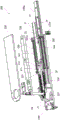
Fig. 1 is an overall perspective view showing an endoscope having a chain locking prevention function according to an embodiment of the present invention.
Fig. 2 is a perspective view showing a second detachable module provided in the operation section of the endoscope having the chain locking prevention function according to the embodiment of the present invention.
Fig. 3 is an overall perspective view showing a direction conversion module provided in an endoscope having a chain locking prevention function according to an embodiment of the present invention.
Fig. 4 is an overall perspective view showing a direction conversion module provided in an endoscope having a chain locking prevention function according to an embodiment of the present invention.
Fig. 5 is a cross-sectional perspective view showing a direction conversion module provided in an endoscope having a chain locking prevention function according to an embodiment of the present invention.
Fig. 6 is an adjusting screw portion showing a connection state between both ends of an upper chain and first and second connection blocks in a direction conversion module of an endoscope having a chain locking prevention function according to an embodiment of the present invention.
Fig. 7a, 7b and 7c are operation state diagrams of a direction conversion module of an endoscope having a chain locking prevention function provided in an embodiment of the present invention.
Fig. 8 is a diagram showing a general endoscope.
Description of the reference numerals
1: endoscope with a lens
21. 22, 23, 24: first, second, third and fourth connection metal lines
Wire (C)
25. 27: upper sprocket and lower sprocket
26. 28: upper chain and lower chain
500: direction conversion module
501. 502, 503, 504: first, second, third and fourth coil springs
511. 512: first connecting block and second connecting block
523. 524: third and fourth connecting blocks
531. 532: first guide rail and second guide rail
533: intermediate guide plate
534. 535: upper guide plate and lower guide plate
Detailed Description
Hereinafter, preferred embodiments of the present invention will be described in detail with reference to the accompanying drawings so that those skilled in the art to which the present invention pertains can easily practice the present invention. However, in the course of describing in detail the structural principles of the preferred embodiment of the present invention, in the event that it is determined that the related well-known functions or structures are not specifically described in detail, the detailed description thereof will be omitted.
Also, throughout the drawings, the same reference numerals are used for portions that perform similar functions and roles.
In addition, throughout the specification, when one portion is "connected" to another portion, this includes a case of "direct connection" and a case of "indirect connection" with other periods interposed therebetween. Further, unless otherwise noted, the term "comprising" one component means that the component further comprises other components, and does not mean that the component is excluded.
As shown in fig. 1, a detachable endoscope 1 according to an embodiment of the present invention includes: an insertion section 10, the distal end of which is inserted into the body when performing an endoscopic operation; an operation unit 20 having a plurality of operation handles; a universal joint 30 electrically connected to the endoscope control and management system; and a detachable unit 1a that mechanically connects the insertion section 10 and the operation section 20 to each other before performing an endoscopic operation, or that separates the insertion section 10 from the operation section 20 after performing an operation.
The insertion portion 10 is formed of a tube of flexible material so as to adjust the direction of insertion into the body, and an illumination imaging portion including a light source for illuminating the body and an image sensor for imaging is provided at the distal end.
The operation unit 20 includes: an upper operation handle 29a for bending the front end of the insertion portion inserted into the body in the up-down direction; and a lower operation handle 29b for bending the tip of the insertion portion inserted into the body in the left-right direction.
An upper sprocket 25 (spline), a lower sprocket 27, and an upper chain 26 and a lower chain 28 are provided in the operation section 20, the upper sprocket 25 and the lower sprocket 27 are provided in the upper operation section handle and the lower operation section handle, respectively, the upper chain 26 and the lower chain 28 are connected to the upper sprocket 25 and the lower sprocket 27, thereby converting selective rotational movement of the upper operation handle and the lower operation handle into linear movement, and each of both ends of the upper chain 26 and the lower chain 28 is disposed in the insertion section with a plurality of connection wires disposed in the operation section as a medium, and is connected to each of the other ends of the plurality of operation wires, one end of which is connected to the inside of the tip of the insertion section.
The upper chain and the lower chain are wound around the upper chain wheel and the lower chain wheel in the middle of the length, and the upper chain wheel and the lower chain wheel rotate by selective rotation based on an upper operation handle and a lower operation handle of a user, so that a pair of the plurality of working wires arranged in the insertion part are converted into linear motion for pulling and pushing, and therefore, the front end of the insertion part bends in the up-down direction or the left-right direction in the body according to the linear motion of the working wires.
An operation switch and an operation button are provided in the operation portion, and an access port for opening and closing the access port and a cover for allowing an operation prop such as an endoscope treatment with a clip to be moved into and out of the insertion portion are provided at a rear end of the insertion portion detachably assembled with a front end of the operation portion by using a detachable unit as a medium when performing an endoscopic operation.
As shown in fig. 1 and 2, the endoscope 1 with a chain locking prevention function according to the preferred embodiment of the present invention includes a direction conversion module 500 for maintaining a linear state of the upper chain 26 and the lower chain 28 which are pulled and pushed when the operation part is rotated, and converting the rotational movement of the upper sprocket 25 and the lower sprocket 27 into the linear movement of the upper chain and the lower chain.
The direction conversion module 500 is applied to the operation unit 20 of the detachable endoscope including a detachable unit that detachably couples the rear end of the insertion unit 10 and the front end of the operation unit 20, but is not limited thereto, and is equally applicable to an integrated endoscope in which the insertion unit and the operation unit are integrally connected to each other and one wire is connected to each other by the connection wire and the operation wire.
The detachable unit includes a first detachable module disposed in the insertion portion and a second detachable module disposed in the operation portion, and when the insertion portion and the operation portion are combined, the operation wire of the first detachable module and the connection wire of the second detachable module are connected to each other.
The first dismounting module comprises: a first working wire and a second working wire which are arranged in parallel in the insertion portion and move in opposite directions so that the tip of the insertion portion is bent in the up-down direction; and third and fourth working wires disposed in parallel with the first and second working wires so as to move the distal end of the insertion portion in the opposite direction so as to bend the distal end in the left-right direction.
The second detachable module 200 includes: a first connecting wire 21 and a second connecting wire 22 connected to both ends of an upper chain wound around the upper sprocket and arranged in parallel; and a third connecting wire 23 and a fourth connecting wire 24 connected to both ends of a lower chain wound around the lower sprocket and arranged in parallel.
The first and second connection wires 21 and 22 are connected to the first and second working wires 11 and 12 arranged in parallel on the upper side of the insertion portion in the drawing to bend the distal end of the insertion portion in the vertical direction, and the third and fourth connection wires 23 and 24 are connected to the third and fourth working wires 13 and 14 arranged in parallel on the lower side of the insertion portion in the drawing to bend the distal end of the insertion portion in the horizontal direction.
The rotation of the upper sprocket and the lower sprocket is performed by a manual rotation operation by a worker who grips an upper operation handle and a lower operation handle provided in the operation unit, but the present invention is not limited thereto, and the rotation may be performed by an additional remote operation unit such as an operation lever that connects a rotation shaft assembled with the upper sprocket and the lower sprocket to a driving unit such as a motor to control the driving unit.
As shown in fig. 3, 4 and 5, the direction conversion module 500 includes: a first connection block 511 and a second connection block 512 which connect both ends of an upper chain 26 wound around the upper sprocket 25 in the middle of a length thereof and arranged side by side with one ends of the first connection wire 21 and the second connection wire 22; and a third connecting block 523 and a fourth connecting block 524, which connect both ends of a lower chain 28, which is wound around the lower sprocket 27 in the middle of the length thereof and is arranged side by side, with one end of each of the third connecting wire 23 and the fourth connecting wire 24.
Locking grooves 511a, 512a, 523a, 524a recessed so as to be locked to locking members 21a, 22a, 23a, 24a are formed in one side surface of the first, second, third, and fourth connection blocks 511, 512, 513, 524, and the locking members 21a, 22a, 23a, 24a are integrally formed with one end of each of the first, second, third, and fourth connection wires.
The locking groove is formed in a groove shape opening outward so that the locking member is inserted and locked, and a wire arrangement groove into which a wire is inserted is formed in each side surface of the first, second, third, and fourth connection blocks 511, 512, 513, and 524 in which the locking groove is formed.
Chain combining parts capable of easily executing the locking connection and unlocking of the locking parts and the locking grooves are arranged between the two ends of the upper chain and the lower chain and the one ends of the first connecting block, the second connecting block, the third connecting block and the fourth connecting block.
As shown in fig. 6, the chain coupling portion includes coupling male screws 505 provided at both ends of the upper chain 26 to rotate, and coupling female screw holes 506 provided at one ends of the first and second connection blocks to be screwed with the coupling male screws.
In a state where the locking grooves 511a, 512a of the first and second connection blocks are configured to lock the locking members 21a, 22a having a substantially T-shape for the first time, the corresponding connection block is pulled toward the chain side by the locking direction rotation of the coupling male screw 505, and the locking members are firmly adhered to the locking grooves for the second time to achieve locking connection so as to prevent the locking members from being separated and separated from the locking grooves.
In contrast, when the coupling male screw is rotated in the loosening direction, the connection block is pushed toward the insertion portion to form a gap between the locking member and the locking groove, and in the loosened state, the locking member is separated from the locking groove to release the locking connection between the connection block and the connection wire, thereby allowing easy separation operation.
That is, the first connecting block 511, the second connecting block 512, the third connecting block 523, and the fourth connecting block 524, the first connecting wire 21, the second connecting wire 22, the third connecting wire 23, and the fourth connecting wire 24 can easily perform the locking connection and the locking release of the locking member and the locking groove by the screw-coupling of the external screw portion for coupling and the internal screw hole for coupling provided at the chain coupling portion between the end portion of the corresponding connecting block and the end portion of the corresponding chain.
The first guide 531 may be disposed between the first connection block 511 and the third connection block 523, and the first guide 531 may be disposed parallel to the upper chain and may contact with one side surface of each of the first connection block and the third connection block formed at an upper-lower interval in the drawing, so that the first guide pulls and pushes the first connection block and the third connection block in opposite directions when the upper operating handle is selectively rotated.
A second rail 532 having a predetermined length is disposed between the second connection block 512 and the fourth connection block 524, and the second rail is disposed in parallel with the lower chain and contacts each side surface of the second connection block and the fourth connection block formed at an upper-lower interval in the drawing, whereby the second rail pulls and pushes the second connection block and the third connection block in opposite directions when the lower operating handle is selectively rotated.
The present invention includes an intermediate guide plate 533 having both ends in contact with the first guide rail 531 and the second guide rail 532, and an upper guide plate 534 disposed and assembled on an upper surface which is a side surface of the intermediate guide plate in contact with each side surface of the first connection block 511 and the second connection block 512, and disposed between the upper chains 26 disposed side by side, and a lower guide plate 535 disposed and assembled on a lower surface which is another side surface of the intermediate guide plate in contact with each side surface of the third connection block 523 and the fourth connection block 524, and disposed between the lower chains 28 disposed side by side.
Thus, the first and second connection blocks and the upper chain are arranged to form guide paths for moving them in opposite directions by the intermediate guide plate 533 provided between the first and second guide rails and the upper and lower guide plates 534 and 535 provided on both sides of the intermediate guide plate, and the third and fourth connection blocks and the lower chain are arranged to form guide paths for moving them in opposite directions.
The direction conversion module 500 includes an upper terminal plate 536, and is assembled to an upper portion of the upper guide plate 534 so as to cover a connection portion between the first connection block 511 and the second connection block 512 and the first connection wire and the second connection wire, and so that one side surface of the first connection block and the second connection block contacts an inner surface of the upper guide plate; and a lower end plate 538 which covers the connection portions of the third connection block 523 and the fourth connection block 524 with the third connection wire 23 and the fourth connection wire 24 and is assembled to the lower portion of the lower guide plate 535 such that one side surface of the third connection block and the fourth connection block contacts the inner surface.
The lower end plate 538 is formed with a mounting rod 538a extending a predetermined length on one side, and the mounting rod 538a is assembled and connected with a second attachment/detachment module provided with the first, second, third, and fourth connection wires, so that a chain cover 537 covering the upper and lower chain wound around the upper and lower sprockets with a length therebetween contacts one ends of first and second guide rails corresponding to the upper and lower sprockets.
On the other hand, the present invention includes a first coil spring 501 and a second coil spring 502 connected to both end portions elongated along both sides to generate elastic restoring force between fixed ends, which are respective ends of the first guide 531 and the second guide 532 corresponding to the first connection wire 21 and the second connection wire 22, and the first connection block 511 and the second connection block 512.
In this case, the first and second connection blocks connected to the first and second connection wires are elastically supported by the first and second coil springs with an external force of a predetermined strength toward the insertion portion side, whereby the linear state of the upper chain wound around the upper sprocket and connected to the first and second connection blocks at both ends thereof can be maintained, and thus, when the operation portion is selectively rotated, pulling and pushing of the upper chain arranged in a linear manner side by side can be smoothly performed without generating a bending portion.
The present invention includes a third coil spring 503 and a fourth coil spring 504 connected to both end portions extending along both sides so as to generate elastic restoring force between the fixed ends of the respective one ends of the first rail 531 and the second rail 532 corresponding to the third connection wire 23 and the fourth connection wire 24 and the third connection block 523 and the fourth connection block 524.
In this case, as in the above, the third connection block and the fourth connection block connected to the third connection wire and the fourth connection wire are elastically supported by the elastic forces of the third coil spring and the fourth coil spring to the insertion portion side with an external force of a predetermined strength, whereby the linear state of the upper chain wound around the lower sprocket and connected to the third connection block and the fourth connection block at both ends thereof can be maintained, and thus, when the operation portion is selectively rotated, pulling and pushing of the lower chain arranged in a linear manner side by side can be smoothly performed without occurrence of a bending portion.
In this case, the fixing ends of the first rail 531 and the second rail 532 include locking pins that lock and fix the respective one ends of the first coil spring 501, the second coil spring 502, the third coil spring 503, and the fourth coil spring 504, and the first rail 531 and the second rail 532 include pin fixing plates 531a and 532a that are assembled to the fixing ends of the one ends of the first rail and the second rail so as to fix the positions of the locking pins.
The first coil spring 501 and the second coil spring 502 transmit the same external force to both ends of the upper chain through the first connection block 511 and the second connection block 512, and the first connection block and the second connection block are connected to the first rail and the second rail in a state of being extended by the same length, so that the linear state of the upper chain is maintained, and the same elastic restoring force is generated.
In the same manner, the third coil spring 503 and the fourth coil spring 504 transmit the same external force to both ends of the lower chain through the third connection block 523 and the fourth connection block 524, and both sides are connected in a state of being extended by the same length between the third connection block and the fourth connection block and the first rail and the second rail, so that the linear state of the lower chain is maintained, thereby generating the same elastic restoring force.
The respective ends of the first coil spring 501 and the second coil spring 502 and the respective ends of the third coil spring 503 and the fourth coil spring 504 may be engaged and connected in a state of being extended by the same length so as to be able to transmit the external force of the same magnitude, but the present invention is not limited thereto, and may be engaged and connected in a state of being extended by different lengths.
Thus, the upper chain wound around the upper sprocket and arranged side by side is elastically supported by the elastic restoring force of the first coil spring and the second coil spring, both ends of which are engaged with the first connecting block and the second connecting block, and the first rail and the second rail, together with the first connecting block and the second connecting block, to the side of the insertion portion with an external force of a predetermined strength, whereby the parallel state of the upper chain arranged side by side and linearly moved in the opposite direction can be stably maintained.
The lower chain wound around the lower sprocket and arranged side by side is elastically supported by an external force of a predetermined strength along with the third and fourth link blocks by elastic restoring forces of the third and fourth coil springs, both ends of which are engaged with the third and fourth link blocks and the first and second guide rails, whereby the upper chain arranged side by side and linearly moved in opposite directions can be stably maintained in a parallel state.
The direction conversion module 500 having the above-described structure rotates one of the upper sprocket and the lower sprocket by rotating one of the upper operating handle and the lower operating handle of the operating portion selectively, and pulls and pushes both ends of one of the upper chain and the lower chain wound around the one of the sprockets in opposite directions.
By pulling and pushing the wire in conjunction with the selective linear movement of the upper chain and the lower chain, the distal end of the insertion portion inserted into the body can be bent in the up-down direction and the left-right direction, and the endoscopic operation can be performed.
As shown in fig. 7a, the first connection block 511 and the second connection block 512 of the direction conversion module 500 are elastically supported to the insertion portion side on the right side in the drawing by an external force caused by elastic restoring forces of the first coil spring 501 and the second coil spring 502 connected in a state of being extended along both sides between the fixed ends of one ends of the first rail and the second rail.
The upper chain 26 wound around the upper sprocket 25 at the middle of the length is arranged side by side with the same length, so that the parallel state and the linear state are maintained, and the first connection block 511 and the second connection block 512 stand by at the same position.
In this initial standby state, as shown in fig. 7b, when the upper sprocket of the rotation shaft rotates in one direction counterclockwise in the drawing by the selective rotation of the operation part, the first connection block 511 pulls the first connection wire together with the first connection block 511 by a predetermined distance, the first connection wire is connected to the first connection block 511, and conversely, the second connection block 512 pushes the second connection wire together with the second connection wire to the insertion part by a predetermined distance corresponding to the pulling distance of the first connection block, and the second connection wire is connected to the second connection block 512.
In this case, the entire length of the first coil spring 501, which is connected between the first connection block 511 and the first guide rail 531 at both ends, increases by a distance corresponding to the distance pulled to both sides and increases the elastic restoring force compared to the initial standby state, whereas the entire length of the second coil spring 502, which is connected between the second connection block 512 and the second guide rail 532, is relatively reduced by a distance corresponding to the pushing distance and decreases the elastic restoring force compared to the initial standby state.
In this case, the elastic restoring forces generated by the first coil spring and the second coil spring are different, but the external force due to the elastic restoring force is maintained in a state of being transmitted to the upper chain wound around the upper sprocket and pushed toward the insertion portion side, whereby the linear state of the upper chain pushed and extended in a long manner can be stably maintained.
In contrast to the above, as shown in fig. 7c, when the upper sprocket of the rotating shaft rotates in the reverse direction and clockwise in the drawing by the selective rotation of the operating portion, the second connection block 512 is pulled toward the operating portion side by a predetermined distance together with the second connection wire, the second connection wire is connected to the second connection block 512, and conversely, the first connection block 511 is pushed toward the insertion portion side by a predetermined distance corresponding to the pulling distance of the second connection wire together with the first connection wire, and the first connection wire is connected to the first connection block 511.
In this case, the entire length of the second coil spring 502, which is connected between the second connection block 512 and the second guide rail 532, is increased by a distance corresponding to the distance pulled to both sides and the elastic restoring force is increased compared to the initial standby state, and conversely, the entire length of the first coil spring 501, which is connected between the first connection block 511 and the first guide rail 531, is relatively decreased by a distance corresponding to the pushing distance and the elastic restoring force is reduced compared to the initial standby state.
In this case, the elastic restoring forces generated by the first coil spring and the second coil spring are different from each other as described above, but the external force due to the elastic restoring force is maintained in a state of being transmitted to the lower chain wound around the lower sprocket and pushed toward the insertion portion side, whereby the linear state of the upper chain pushed and extended long can be stably maintained.
Therefore, since the external force generated by the elastic restoring force of the first coil spring and the second coil spring is transmitted to the upper chain which is pulled and pushed in the opposite direction when the operation portion is selectively rotated, the linear state of the upper chain can be maintained, and thus, the phenomenon that the connecting rod connecting portion of the chain is unnecessarily bent to be narrowed with other members or noise is generated can be prevented, and the pulling and pushing of the upper chain can be smoothly performed.
On the other hand, during the period in which the lower chain wound around the lower sprocket is pulled and pushed in the opposite direction by the lower operating handle of the operating portion, an external force due to the elastic restoring forces of the third coil spring and the fourth coil spring is applied to the lower chain, whereby the side-by-side lower chain is maintained in a straight state as the upper chain, and therefore, a detailed description thereof will be omitted.
The present invention described above is not limited to the embodiments and drawings described above, and various substitutions, modifications and changes can be made by those skilled in the art without departing from the technical spirit of the present invention.
Claims (5)
1. An endoscope having a chain locking prevention function, comprising: an insertion part provided with an illumination shooting part at the front end; and an operation part having an upper chain and a lower chain which are wound around the upper chain and the lower chain of the rotation shaft in the middle of the length thereof, wherein the front end of the insertion part is bent,
the endoscope having the function of preventing chain locking is characterized in that,
comprises a direction conversion module for maintaining the linear state of the upper chain and the lower chain which are pulled and pushed when the operation part rotates, converting the rotation motion of the upper chain wheel and the lower chain wheel into the linear motion of the upper chain and the lower chain,
the direction conversion module includes:
a first connecting block and a second connecting block which are connected with each other and connect the two ends of the upper chain with the respective ends of the first connecting metal wire and the second connecting metal wire of the operation part;
a third connecting block and a fourth connecting block which connect both ends of the lower chain with respective ends of a third connecting wire and a fourth connecting wire of the operation part;
a first guide rail of a predetermined length disposed between the first connection block and the third connection block, and guiding sliding of the first connection block and the third connection block;
a second guide rail of a predetermined length disposed between the second connection block and the fourth connection block, and guiding sliding of the second connection block and the fourth connection block;
a first coil spring and a second coil spring, both end portions of which are connected between one end of the first rail and the first connection block and between one end of the second rail and the second connection block, and elastically supporting the first connection block and the second connection block connected to the first connection wire and the second connection wire toward the insertion portion side; and
a third coil spring and a fourth coil spring, both end portions of which are connected between one end of the first rail and the third connection block and between one end of the second rail and the fourth connection block, and elastically supporting the third connection block and the fourth connection block connected to the third connection wire and the fourth connection wire toward the insertion portion side;
the first, second, third and fourth connecting blocks include locking grooves recessed to be locked with locking members provided at one ends of the first, second, third and fourth connecting wires;
the two ends of the upper chain and the lower chain are combined with one end of the first connecting block, the second connecting block, the third connecting block and the fourth connecting block by taking the chain combination part as a medium,
the chain coupling portion includes:
external threads for coupling are provided at both ends of the upper chain and the lower chain to rotate; and
and an internal thread hole for coupling formed at one end of the first, second, third and fourth connection blocks so as to be screwed with the external thread for coupling.
2. The endoscope with a chain locking prevention function according to claim 1, wherein the direction conversion module comprises:
the middle guide plate is connected between the first guide rail and the second guide rail at two ends;
an upper guide plate which is assembled while being placed on one side of an intermediate guide plate, and which is positioned between upper chains arranged side by side, the intermediate guide plate being in contact with each side of the first and second connection blocks; and
and a lower guide plate which is assembled by being placed on the other side surface of the intermediate guide plate and is positioned between the lower chains arranged side by side, wherein the intermediate guide plate is contacted with each side surface of the third connecting block and the fourth connecting block.
3. The endoscope with a chain locking prevention function according to claim 2, wherein the direction conversion module comprises:
an upper terminal plate which covers the connection parts of the first connection block and the second connection block with the first connection metal wire and the second connection metal wire, and is assembled with the upper guide plate in a manner that one side surface of the first connection block and one side surface of the second connection block are contacted with the inner surface; and
and a lower terminal plate which covers the connection parts of the third connection block and the fourth connection block and the third connection metal wire and the fourth connection metal wire, and is assembled with the lower guide plate in a manner that one side surface of the third connection block and one side surface of the fourth connection block are contacted with the inner surface.
4. The endoscope having a chain locking prevention function according to any one of claims 1 to 3, wherein the first coil spring and the second coil spring are connected in a state of generating elastic restoring force by being extended along both sides in the same length so that external forces of the same magnitude can be transmitted to both ends of the upper chain by the first connection block and the second connection block.
5. The endoscope having a chain locking prevention function according to any one of claims 1 to 3, wherein the third coil spring and the fourth coil spring are connected in a state of generating elastic restoring force by extending along both sides in the same length so that external forces of the same magnitude can be transmitted to both ends of the lower chain by the third connection block and the fourth connection block.
Applications Claiming Priority (2)
| Application Number | Priority Date | Filing Date | Title |
|---|---|---|---|
| KR1020190112949A KR102325265B1 (en) | 2019-09-11 | 2019-09-11 | Endoscope with chain locking function |
| KR10-2019-0112949 | 2019-09-11 |
Publications (2)
| Publication Number | Publication Date |
|---|---|
| CN112472006A CN112472006A (en) | 2021-03-12 |
| CN112472006B true CN112472006B (en) | 2023-06-23 |
Family
ID=74644677
Family Applications (1)
| Application Number | Title | Priority Date | Filing Date |
|---|---|---|---|
| CN202010914780.6A Active CN112472006B (en) | 2019-09-11 | 2020-09-03 | Endoscope with chain locking prevention function |
Country Status (5)
| Country | Link |
|---|---|
| US (1) | US11998174B2 (en) |
| JP (1) | JP6905216B2 (en) |
| KR (1) | KR102325265B1 (en) |
| CN (1) | CN112472006B (en) |
| DE (1) | DE102020211128A1 (en) |
Families Citing this family (5)
| Publication number | Priority date | Publication date | Assignee | Title |
|---|---|---|---|---|
| US11974722B2 (en) * | 2019-10-07 | 2024-05-07 | Boston Scientific Scimed, Inc. | Endoscopic device with interchangeable shaft |
| WO2022178306A1 (en) | 2021-02-19 | 2022-08-25 | Boston Scientific Scimed Inc. | Modular medical devices and methods of using the same |
| CN114366303B (en) * | 2021-12-27 | 2024-03-15 | 北京双翼麒电子有限公司 | Endoscope robot and endoscope operating system |
| KR102770251B1 (en) * | 2022-07-04 | 2025-02-18 | 한국항공대학교산학협력단 | Endoscope motorization robotic system and endoscope motorization driving method using this |
| US12127805B1 (en) * | 2023-04-29 | 2024-10-29 | Syncrobotix, Inc. | Highly maneuverable surgical catheter and drive system |
Citations (1)
| Publication number | Priority date | Publication date | Assignee | Title |
|---|---|---|---|---|
| CN107320057A (en) * | 2017-08-12 | 2017-11-07 | 北京华信佳音医疗科技发展有限责任公司 | A kind of endoscope handle and its application method of use rack-driving |
Family Cites Families (14)
| Publication number | Priority date | Publication date | Assignee | Title |
|---|---|---|---|---|
| US5320021A (en) * | 1993-02-05 | 1994-06-14 | Heintz Farrell E | Universal chain wrench and tools |
| AU2003259483A1 (en) * | 2002-10-11 | 2004-05-04 | Koninklijke Philips Electronics N.V. | Control mechanism for an endoscope |
| JP4875364B2 (en) * | 2006-01-13 | 2012-02-15 | オリンパスメディカルシステムズ株式会社 | Rotating self-propelled endoscope |
| KR100673412B1 (en) * | 2006-07-03 | 2007-01-24 | 주식회사 액츠비전 | Medical endoscope with removable insert |
| KR101091999B1 (en) | 2009-11-30 | 2011-12-08 | 주식회사 인트로메딕 | Insert device for endoscope, handle devices for endoscope, endoscope |
| KR101206014B1 (en) * | 2010-08-10 | 2012-11-28 | 이성용 | Apparatus for adjusting the bending of endoscope tube |
| JP5840033B2 (en) * | 2012-03-02 | 2016-01-06 | オリンパス株式会社 | Endoscope |
| WO2013154048A1 (en) * | 2012-04-12 | 2013-10-17 | オリンパスメディカルシステムズ株式会社 | Endoscope |
| EP2837323B1 (en) * | 2012-10-24 | 2017-01-04 | Olympus Corporation | Bending operation apparatus for endoscope and endoscope including the bending operation apparatus |
| WO2015166877A1 (en) * | 2014-04-28 | 2015-11-05 | オリンパス株式会社 | Operating mechanism for insertion device, and insertion device |
| JP5959765B2 (en) * | 2014-05-15 | 2016-08-02 | オリンパス株式会社 | Endoscope |
| WO2015198649A1 (en) * | 2014-06-24 | 2015-12-30 | オリンパス株式会社 | Bending operation mechanism for endoscope |
| KR101783225B1 (en) | 2016-02-26 | 2017-09-29 | 주식회사 현주인테크 | Wire connecting unit for divisible endoscope having elastic structure |
| JP6407495B2 (en) * | 2016-10-25 | 2018-10-17 | オリンパス株式会社 | Endoscope |
-
2019
- 2019-09-11 KR KR1020190112949A patent/KR102325265B1/en active Active
-
2020
- 2020-08-28 JP JP2020144491A patent/JP6905216B2/en active Active
- 2020-09-03 CN CN202010914780.6A patent/CN112472006B/en active Active
- 2020-09-03 DE DE102020211128.6A patent/DE102020211128A1/en active Pending
- 2020-09-08 US US17/014,340 patent/US11998174B2/en active Active
Patent Citations (1)
| Publication number | Priority date | Publication date | Assignee | Title |
|---|---|---|---|---|
| CN107320057A (en) * | 2017-08-12 | 2017-11-07 | 北京华信佳音医疗科技发展有限责任公司 | A kind of endoscope handle and its application method of use rack-driving |
Also Published As
| Publication number | Publication date |
|---|---|
| DE102020211128A1 (en) | 2021-03-11 |
| US11998174B2 (en) | 2024-06-04 |
| CN112472006A (en) | 2021-03-12 |
| KR102325265B1 (en) | 2021-11-11 |
| US20210068619A1 (en) | 2021-03-11 |
| KR20210031230A (en) | 2021-03-19 |
| JP6905216B2 (en) | 2021-07-21 |
| JP2021041156A (en) | 2021-03-18 |
Similar Documents
| Publication | Publication Date | Title |
|---|---|---|
| CN112472006B (en) | Endoscope with chain locking prevention function | |
| US11642007B2 (en) | Detachable endoscope having wire buffer function | |
| US11642006B2 (en) | Detachable endoscope with adjustable bending angle | |
| CN112472002B (en) | Detachable endoscope | |
| JP4350755B2 (en) | Detachable electric bending endoscope | |
| EP3345552B1 (en) | Natural channel-based microsurgical device | |
| CN112472001B (en) | Detachable endoscope | |
| US20150164305A1 (en) | Endoscope | |
| US20080287738A1 (en) | Motor-driven bending endoscope | |
| US11317785B2 (en) | Endoscope head and endoscope provided therewith | |
| JP2002078675A (en) | Motor operated angle type electronic endoscope system | |
| US20230225587A1 (en) | Detachable endoscope | |
| US9339168B2 (en) | Endoscope operation portion structure | |
| JP4433107B2 (en) | Endoscope angle control wire guide device | |
| CN100577085C (en) | Insertion part detachable electric curved endoscope | |
| JP3092997B2 (en) | Endoscope | |
| CN216135926U (en) | Laparoscope ultrasonic probe | |
| CN116211403A (en) | A drive control element, handle and object extractor of an object extractor | |
| KR20100057945A (en) | An elongate multijoint apparatus and a link comprising the same |
Legal Events
| Date | Code | Title | Description |
|---|---|---|---|
| PB01 | Publication | ||
| PB01 | Publication | ||
| SE01 | Entry into force of request for substantive examination | ||
| SE01 | Entry into force of request for substantive examination | ||
| GR01 | Patent grant | ||
| GR01 | Patent grant |