JP7614485B2 - Laser distance measurement device, object detection system - Google Patents
Laser distance measurement device, object detection system Download PDFInfo
- Publication number
- JP7614485B2 JP7614485B2 JP2020080313A JP2020080313A JP7614485B2 JP 7614485 B2 JP7614485 B2 JP 7614485B2 JP 2020080313 A JP2020080313 A JP 2020080313A JP 2020080313 A JP2020080313 A JP 2020080313A JP 7614485 B2 JP7614485 B2 JP 7614485B2
- Authority
- JP
- Japan
- Prior art keywords
- unit
- laser distance
- person
- target space
- laser
- Prior art date
- Legal status (The legal status is an assumption and is not a legal conclusion. Google has not performed a legal analysis and makes no representation as to the accuracy of the status listed.)
- Active
Links
- 238000005259 measurement Methods 0.000 title claims description 100
- 238000001514 detection method Methods 0.000 title claims description 53
- 238000000034 method Methods 0.000 claims description 56
- 230000008569 process Effects 0.000 claims description 56
- 230000005856 abnormality Effects 0.000 claims description 46
- 230000008859 change Effects 0.000 claims description 6
- 238000010586 diagram Methods 0.000 description 22
- 230000005855 radiation Effects 0.000 description 13
- 238000009434 installation Methods 0.000 description 6
- 230000000694 effects Effects 0.000 description 5
- FFBHFFJDDLITSX-UHFFFAOYSA-N benzyl N-[2-hydroxy-4-(3-oxomorpholin-4-yl)phenyl]carbamate Chemical compound OC1=C(NC(=O)OCC2=CC=CC=C2)C=CC(=C1)N1CCOCC1=O FFBHFFJDDLITSX-UHFFFAOYSA-N 0.000 description 4
- 230000003287 optical effect Effects 0.000 description 4
- 238000004381 surface treatment Methods 0.000 description 4
- 230000006870 function Effects 0.000 description 3
- 230000007257 malfunction Effects 0.000 description 3
- 238000002310 reflectometry Methods 0.000 description 3
- 230000008901 benefit Effects 0.000 description 2
- 239000011248 coating agent Substances 0.000 description 2
- 238000000576 coating method Methods 0.000 description 2
- NIXOWILDQLNWCW-UHFFFAOYSA-N acrylic acid group Chemical group C(C=C)(=O)O NIXOWILDQLNWCW-UHFFFAOYSA-N 0.000 description 1
- 230000001186 cumulative effect Effects 0.000 description 1
- 230000003247 decreasing effect Effects 0.000 description 1
- 239000000428 dust Substances 0.000 description 1
- 230000004907 flux Effects 0.000 description 1
- 239000011521 glass Substances 0.000 description 1
- 239000000463 material Substances 0.000 description 1
- 239000003973 paint Substances 0.000 description 1
Images


Classifications
-
- G—PHYSICS
- G01—MEASURING; TESTING
- G01S—RADIO DIRECTION-FINDING; RADIO NAVIGATION; DETERMINING DISTANCE OR VELOCITY BY USE OF RADIO WAVES; LOCATING OR PRESENCE-DETECTING BY USE OF THE REFLECTION OR RERADIATION OF RADIO WAVES; ANALOGOUS ARRANGEMENTS USING OTHER WAVES
- G01S17/00—Systems using the reflection or reradiation of electromagnetic waves other than radio waves, e.g. lidar systems
- G01S17/02—Systems using the reflection of electromagnetic waves other than radio waves
- G01S17/06—Systems determining position data of a target
- G01S17/08—Systems determining position data of a target for measuring distance only
- G01S17/10—Systems determining position data of a target for measuring distance only using transmission of interrupted, pulse-modulated waves
-
- G—PHYSICS
- G01—MEASURING; TESTING
- G01S—RADIO DIRECTION-FINDING; RADIO NAVIGATION; DETERMINING DISTANCE OR VELOCITY BY USE OF RADIO WAVES; LOCATING OR PRESENCE-DETECTING BY USE OF THE REFLECTION OR RERADIATION OF RADIO WAVES; ANALOGOUS ARRANGEMENTS USING OTHER WAVES
- G01S17/00—Systems using the reflection or reradiation of electromagnetic waves other than radio waves, e.g. lidar systems
- G01S17/02—Systems using the reflection of electromagnetic waves other than radio waves
- G01S17/50—Systems of measurement based on relative movement of target
- G01S17/58—Velocity or trajectory determination systems; Sense-of-movement determination systems
-
- G—PHYSICS
- G01—MEASURING; TESTING
- G01S—RADIO DIRECTION-FINDING; RADIO NAVIGATION; DETERMINING DISTANCE OR VELOCITY BY USE OF RADIO WAVES; LOCATING OR PRESENCE-DETECTING BY USE OF THE REFLECTION OR RERADIATION OF RADIO WAVES; ANALOGOUS ARRANGEMENTS USING OTHER WAVES
- G01S7/00—Details of systems according to groups G01S13/00, G01S15/00, G01S17/00
- G01S7/48—Details of systems according to groups G01S13/00, G01S15/00, G01S17/00 of systems according to group G01S17/00
- G01S7/481—Constructional features, e.g. arrangements of optical elements
- G01S7/4811—Constructional features, e.g. arrangements of optical elements common to transmitter and receiver
- G01S7/4813—Housing arrangements
-
- G—PHYSICS
- G01—MEASURING; TESTING
- G01S—RADIO DIRECTION-FINDING; RADIO NAVIGATION; DETERMINING DISTANCE OR VELOCITY BY USE OF RADIO WAVES; LOCATING OR PRESENCE-DETECTING BY USE OF THE REFLECTION OR RERADIATION OF RADIO WAVES; ANALOGOUS ARRANGEMENTS USING OTHER WAVES
- G01S7/00—Details of systems according to groups G01S13/00, G01S15/00, G01S17/00
- G01S7/48—Details of systems according to groups G01S13/00, G01S15/00, G01S17/00 of systems according to group G01S17/00
- G01S7/481—Constructional features, e.g. arrangements of optical elements
- G01S7/4814—Constructional features, e.g. arrangements of optical elements of transmitters alone
-
- G—PHYSICS
- G01—MEASURING; TESTING
- G01S—RADIO DIRECTION-FINDING; RADIO NAVIGATION; DETERMINING DISTANCE OR VELOCITY BY USE OF RADIO WAVES; LOCATING OR PRESENCE-DETECTING BY USE OF THE REFLECTION OR RERADIATION OF RADIO WAVES; ANALOGOUS ARRANGEMENTS USING OTHER WAVES
- G01S7/00—Details of systems according to groups G01S13/00, G01S15/00, G01S17/00
- G01S7/48—Details of systems according to groups G01S13/00, G01S15/00, G01S17/00 of systems according to group G01S17/00
- G01S7/481—Constructional features, e.g. arrangements of optical elements
- G01S7/4817—Constructional features, e.g. arrangements of optical elements relating to scanning
-
- G—PHYSICS
- G01—MEASURING; TESTING
- G01S—RADIO DIRECTION-FINDING; RADIO NAVIGATION; DETERMINING DISTANCE OR VELOCITY BY USE OF RADIO WAVES; LOCATING OR PRESENCE-DETECTING BY USE OF THE REFLECTION OR RERADIATION OF RADIO WAVES; ANALOGOUS ARRANGEMENTS USING OTHER WAVES
- G01S7/00—Details of systems according to groups G01S13/00, G01S15/00, G01S17/00
- G01S7/48—Details of systems according to groups G01S13/00, G01S15/00, G01S17/00 of systems according to group G01S17/00
- G01S7/497—Means for monitoring or calibrating
Landscapes
- Engineering & Computer Science (AREA)
- Physics & Mathematics (AREA)
- Computer Networks & Wireless Communication (AREA)
- General Physics & Mathematics (AREA)
- Radar, Positioning & Navigation (AREA)
- Remote Sensing (AREA)
- Electromagnetism (AREA)
- Optical Radar Systems And Details Thereof (AREA)
- Measurement Of Optical Distance (AREA)
Description
本発明は、レーザ光を用いて対象空間内に存在する物体までの距離を計測するレーザ距離計測装置に関する。 The present invention relates to a laser distance measurement device that uses laser light to measure the distance to an object present in a target space.
従来、レーザ光に用いて対象空間内に存在する物体までの距離を計測するレーザ距離計測装置が知られている。このようなレーザ距離計測装置は、物体で反射した反射光を受光するまでの時間に基づいて物体までの距離を計測している。そして、例えば、特許文献1では、反射光のレベルに応じた閾値を設けることにより、低反射率の物体を検出できるようにすることが提案されている。
Conventionally, laser distance measurement devices are known that use laser light to measure the distance to an object present in a target space. Such laser distance measurement devices measure the distance to an object based on the time it takes for the reflected light reflected by the object to be received. For example,
しかしながら、レーザ距離計測装置は、その計測原理上、反射光を受光できなかったり反射光のレベルが低すぎてノイズに紛れてしまったりすることによって検出が困難になる物体が、低反射率の物体以外にも想定される。例えば、鏡面のような表面処理が施されている物体は、そもそもの反射率が低いことに加えて、レーザ距離計測装置との位置関係によっては、放射されたレーザ光がレーザ距離計測装置とは別の方向に反射してしまう可能性があり、検出が困難になることが想定される。また、曲面を有する物体も、放射されたレーザ光が走査平面からずれた方向に反射されてしまう可能性があり、検出が困難になることが想定される。 However, due to the measurement principle of the laser distance measuring device, there are other objects besides those with low reflectivity that are difficult to detect because the reflected light cannot be received or the level of reflected light is so low that it is blended into noise. For example, objects that have been treated with a mirror-like surface not only have low reflectivity to begin with, but depending on their position relative to the laser distance measuring device, the emitted laser light may be reflected in a direction different from that of the laser distance measuring device, making detection difficult. In addition, objects with curved surfaces may also have the potential to cause the emitted laser light to be reflected in a direction deviated from the scanning plane, making detection difficult.
そして、このような検出が困難になる物体には、例えば表面にコーティング塗装が施されている車両のように、レーザ距離計測装置の一般的な利用形態において検出対象になり得るものが含まれている。 Objects that are difficult to detect include those that could be detected in typical usage scenarios of laser distance measuring devices, such as vehicles with coating paint on their surfaces.
本発明は、上記した課題に鑑みてなされたものであり、その目的は、検出が困難な物体の検出を可能にするレーザ距離計測装置、物体検出システムを提供することにある。 The present invention was made in consideration of the above-mentioned problems, and its purpose is to provide a laser distance measuring device and object detection system that enables the detection of objects that are difficult to detect.
請求項1に記載した発明では、レーザ距離計測装置は、レーザ光を発生させるレーザ光発生部と、レーザ光発生部が発生させたレーザ光を、対象空間に向けて反射方向を変化させつつ放射する反射部と、反射部を駆動して反射方向を変化させる駆動部と、対象空間に存在する物体によって反射された反射光を受光する受光部と、レーザ光発生部でレーザ光を発生させてから受光部で反射光が受光されるまでの時間に基づいて、対象空間内に存在する物体までの距離および方位を計測する測距部と、測距部の計測結果に基づいて、対象空間内の予め定められた位置に設けられている基準物を検出できるか否かを判定する基準物判定部と、測距部の計測結果に基づいて、対象空間内の予め定められた位置に設けられている基準物を検出できるか否かを判定する基準物判定部と、基準物判定部の判定結果に基づいて基準物との間における物体の有無を判定する物体判定部とを備えている。
In the invention described in
これにより、まず、レーザ距離測定装置は、上記した物体の表面処理や表面形状によって距離の計測が困難な物体であっても、少なくとも物体が存在するか否かを判定することができる。 As a result, first of all, the laser distance measuring device can at least determine whether or not an object exists, even if it is difficult to measure the distance to the object due to the surface treatment or surface shape of the object described above.
さて、レーザ距離計測装置の対象空間としては、例えば一方通行の道路や高速道路への誘導路など移動方向が制限されている場合や、そもそも進入が禁止されている場所なども想定される。その場合、物体までの距離が計測できなかったとしても、侵入者や逆走による例えば車両の侵入の検知することができればよい場合がある。 The target space for a laser distance measuring device may be, for example, a one-way road or a taxiway leading to a highway where the direction of movement is restricted, or a place where entry is prohibited in the first place. In such cases, even if the distance to an object cannot be measured, it may be sufficient to detect an intruder or the intrusion of a vehicle driving in the wrong direction.
そこで、レーザ距離計測装置は、物体判定部の判定結果に基づいて物体の移動方向を判定する移動方向判定部を備え、対象空間内に複数設けられている基準物との間の物体の有無をそれぞれ判定し、物体があると判定された順番に基づいて、物体の移動方向を判定する。これにより、レーザ距離計測装置は、物体の移動方向を判定することができ、例えば進入禁止場所への侵入者や、一方通行の道路や高速道路への誘導路への逆走などを検出することができる。 The laser distance measuring device is provided with a movement direction determining unit that determines the movement direction of an object based on the determination result of the object determining unit, determines the presence or absence of an object between the object and multiple reference objects provided in the target space, and determines the movement direction of the object based on the order in which the presence of the object is determined. This allows the laser distance measuring device to determine the movement direction of an object, and to detect, for example, an intruder entering a no-entry area, or a person driving the wrong way onto a one-way road or a taxiway leading to a highway.
請求項2に記載した発明では、レーザ距離計測装置は、レーザ光を発生させるレーザ光発生部と、レーザ光発生部が発生させたレーザ光を、対象空間に向けて反射方向を変化させつつ放射する反射部と、反射部を駆動して反射方向を変化させる駆動部と、対象空間に存在する物体によって反射された反射光を受光する受光部と、レーザ光発生部でレーザ光を発生させてから受光部で反射光が受光されるまでの時間に基づいて、対象空間内に存在する物体までの距離および方位を計測する測距部と、測距部の計測結果に基づいて、対象空間内の予め定められた位置に設けられている基準物を検出できるか否かを判定する基準物判定部と、基準物判定部の判定結果に基づいて、基準物との間における物体の有無を判定する物体判定部と、を備えている。
In the invention described in
これにより、まず、レーザ距離測定装置は、上記した物体の表面処理や表面形状によって距離の計測が困難な物体であっても、少なくとも物体が存在するか否かを判定することができる。 As a result, first of all, the laser distance measuring device can at least determine whether or not an object exists, even if it is difficult to measure the distance to the object due to the surface treatment or surface shape of the object described above.
さて、レーザ距離計測装置の対象空間としては、例えば踏切のように電車が通る際に進入が禁止されている場所などが想定される。その場合、物体までの距離が計測できなかったとしても、人が存在することが識別できれば、警報を鳴らすなどの安全対策をとることができるようになると考えられる。 The target space for a laser distance measuring device may be, for example, a railroad crossing, where entry is prohibited when a train is passing. In that case, even if the distance to an object cannot be measured, if the presence of a person can be identified, it may be possible to take safety measures, such as sounding an alarm.
そこで、レーザ距離計測装置は、物体判定部の判定結果に基づいて人を識別する人識別部を備え、隣り合うように複数設けられている複数の基準物との間の物体の有無をそれぞれ判定し、物体があると判定された際、隣り合う基準物との間の物体の有無に基づいて物体が人であるか否かを識別する。これにより、人の進入などを検出することができる。 The laser distance measuring device is therefore equipped with a person identification unit that identifies people based on the judgment results of the object judgment unit, and judges the presence or absence of an object between a number of adjacent reference objects. When it is judged that an object is present, it identifies whether the object is a person or not based on the presence or absence of an object between the adjacent reference objects. This makes it possible to detect the intrusion of a person, etc.
請求項3に記載した発明では、レーザ距離計測装置は、レーザ光を発生させるレーザ光発生部と、レーザ光発生部が発生させたレーザ光を、対象空間に向けて反射方向を変化させつつ放射する反射部と、反射部を駆動して反射方向を変化させる駆動部と、対象空間に存在する物体によって反射された反射光を受光する受光部と、レーザ光発生部でレーザ光を発生させてから受光部で反射光が受光されるまでの時間に基づいて、対象空間内に存在する物体までの距離および方位を計測する測距部と、測距部の計測結果に基づいて、対象空間内の予め定められた位置に設けられている基準物を検出できるか否かを判定する基準物判定部と、基準物判定部の判定結果に基づいて、基準物との間における物体の有無を判定する物体判定部とを備えている。
In the invention described in
これにより、まず、レーザ距離測定装置は、上記した物体の表面処理や表面形状によって距離の計測が困難な物体であっても、少なくとも物体が存在するか否かを判定することができる。 As a result, first of all, the laser distance measuring device can at least determine whether or not an object exists, even if it is difficult to measure the distance to the object due to the surface treatment or surface shape of the object described above.
レーザ距離測定装置は屋外に設置されることが想定され、また、基準物も屋外に設置されることが想定される。そのような場合には、レーザ距離測定装置や基準物にゴミや汚れが付着したり、物理的に損傷したり、外力が加えられてレーザ距離測定装置や基準物の向きや位置がずれたりすることが想定される。 It is assumed that the laser distance measuring device will be installed outdoors, and that the reference object will also be installed outdoors. In such cases, it is assumed that the laser distance measuring device or the reference object will become contaminated with dust or dirt, be physically damaged, or be subjected to external forces, causing the orientation or position of the laser distance measuring device or the reference object to shift.
また、その場合には、基準物が検出されなくなることから、物体があると誤判定される恐れがある。さらに、誤判定ではなくても、例えば踏切内での立ち往生している状況も想定される。 In that case, the reference object will not be detected, and there is a risk of the system misjudging the presence of an object. Furthermore, even if there is no misjudgment, there may be a situation where the vehicle is stuck, for example, at a railroad crossing.
そこで、レーザ距離計測装置は、異常の有無を判定する異常判定部を備え、予め定められている異常判定時間を超えて物体があると継続して判定されている場合、異常があると判定する。これにより、誤判定するおそれを抑制することができるとともに、例えば基準物の故障や汚れ、レーザ距離計測装置または基準物の向きがずれた位置ずれなどの異常、あるいは、踏切内での立ち往生などの異常を検出することができる。 The laser distance measuring device is therefore equipped with an abnormality determination unit that determines whether or not there is an abnormality, and if it is determined that an object is continuously present for a period exceeding a predetermined abnormality determination time, it determines that there is an abnormality. This makes it possible to reduce the risk of erroneous determination, and to detect abnormalities such as, for example, a malfunction or dirt on the reference object, a misalignment of the laser distance measuring device or the reference object, or a stall at a railroad crossing.
請求項4に記載した発明では、物体判定部は、隣り合うように少なくとも3つ以上設けられている基準物との間の物体の有無を判定する。これにより、隣り合うように設けられている各基準物との間の物体の有無をそれぞれ判定することによって、例えば中央の基準物についてのみ物体ありと判定され、他の基準物との間に物体なしと判定された場合には、基準物の大きさに基づいて、物体の大きさを判定することができる。
In the invention described in
請求項5に記載した発明では、物体判定部は、隣り合うように設けられていて、少なくとも1つが人の胴体よりも小さくなるように設けられているとともに、隣り合う基準物との間が人の胴体より大きく設けられている複数の基準物との間の物体の有無を判定する。これにより、検出された物体が人であるか否かを判定することができる。これにより、複数の物体が存在することが想定される状況において、複数の人が検出されたのか、人と人以外の物体例えば車両が検出されたのかを判定することができる。
In the invention described in
請求項6に記載した発明では、基準物は対象空間内に隣り合うように所定の間隔で複数設けられており、複数の基準物との間に物体があると判定された際、基準物との間以外における物体の検出結果に基づいて、物体が複数の人であるか、または、人と人以外の物体であるかを識別する。これにより、複数の物体が存在することが想定される状況において、複数の人が検出されたのか、人と人以外の物体例えば車両が検出されたのかを判定することができる。
In the invention described in
請求項7に記載した発明では、物体検出システムは、レーザ光を発生させるレーザ光発生部、レーザ光発生部が発生させたレーザ光を対象空間に向けて反射方向を変化させつつ放射する反射部、反射部を駆動して反射方向を変化させる駆動部、対象空間に存在する物体によって反射した反射光を受光する受光部、およびレーザ光発生部でレーザ光を発生させてから受光部で反射光が受光されるまでの時間に基づいて対象空間内に存在する物体までの距離および方位を計測する測距部を備えるレーザ距離計測装置と、測距部の計測結果に基づいて対象空間内の予め定められた位置に設けられている基準物を検出できるか否かを判定する基準物判定部、および基準物判定部の判定結果に基づいて基準物との間における物体の有無を判定する物体判定部を備える管理装置と、を備え、基準物は、対象空間内に複数設けられており、物体判定部は、複数の基準物との間の物体の有無をそれぞれ判定し、移動方向判定部は、物体があると判定された順番に基づいて、物体の移動方向を判定する。
In the invention described in
このような構成の物体検出システムによっても、物体の表面処理や表面形状によって距離の計測が困難であっても、その物体の有無を検出することが可能となる。したがって、検出が困難な物体の検出が可能になるなど、上記したレーザ距離測定装置と同様の効果を得ることができる。 An object detection system configured in this way can detect the presence or absence of an object even if the object's surface treatment or surface shape makes it difficult to measure the distance. Therefore, it is possible to obtain the same effects as the laser distance measuring device described above, such as making it possible to detect objects that are difficult to detect.
以下、複数の実施形態について図面を参照しながら説明する。また、各実施形態で実質的に共通する部位には同一符号を付すものとする。 Several embodiments will be described below with reference to the drawings. In addition, parts that are substantially common to each embodiment will be given the same reference numerals.
(第1実施形態)
以下、第1実施形態につて説明する。図1に示すように、本実施形態のレーザ距離計測装置1は、筐体2内にレーザ光発生部3、受光部4、制御回路部5などを備えている。このレーザ距離計測装置1は、レーザ光を放射し、対象空間に存在する物体で反射したレーザ光を受光することにより、対象空間に存在する物体までの距離とその物体の方位とを検出する。図1では、放射されたレーザ光を放射光6と称し、反射してきたレーザ光を反射光7と称する。
First Embodiment
A first embodiment will be described below. As shown in Fig. 1, a laser
具体的には、筐体2は、概ね筒状に形成されており、その壁部に、透明なガラス材やアクリル材などで形成されていて放射光6を対象空間に通過させる窓部8が筐体2の周方向に設けられている。レーザ光発生部3は、例えばレーザダイオードで構成されており、パルス状のレーザ光を発生させる。受光部4は、例えばフォトダイオードで構成されており、物体で反射した反射光7を検出して電気信号に変換する。
Specifically, the
レーザ光発生部3の光軸上には、コリメートレンズ9および穴あきミラー10が配置されている。コリメートレンズ9は、レーザ光発生部3で発生したレーザ光を平行光に変換する。穴あきミラー10は、平板状に形成されていて、その中心部に形成されている貫通孔がレーザ光発生部3の光軸上に位置する状態で、光軸に対して所定角度で傾斜するように配置されている。この穴あきミラー10の下側の面は反射面となっていて、受光部4に向けて光を反射させる。
A
穴あきミラー10の下方には、反射部としての回転ミラー11が設けられている。回転ミラー11は、レーザ光発生部3の光軸方向に延びる中心軸を中心として回動し、その中心軸上に焦点位置が設定されている凹面鏡によって、レーザ光を外部に向けて反射する。これにより、レーザ距離計測装置1から放射光6が放射される。また、反射部は、外部からの反射光7を穴あきミラー10の方向に反射する。
A rotating
回転ミラー11は、駆動部12によって回転駆動される。駆動部12は、例えばモータやエンコーダにより構成されており、反射部を回転駆動することにより、放射光6の放射方向を所定ステップごとに変化させる。これにより、レーザ距離計測装置1から対象空間に向けて、平面視にて扇形に放射光6が放射される。このとき、駆動部12は、反射部を1秒間に数回~数十回の速度で回転駆動する。
The rotating
制御回路部5は、図2に示すように、例えばCPU、ROMおよびRAMなどを有するマイクロコンピュータで構成されている制御部20、レーザ光発生部3を駆動するためのLD駆動回路21、駆動部12を駆動するためのモータ駆動回路22、受光部4からの信号を増幅する増幅回路23、各種の信号を出力したり通信したりするための出力回路24を備えている。
As shown in FIG. 2, the
制御部20は、ROMなどに記憶されているプログラムを実行することによりレーザ距離計測装置1の全体を制御する。具体的には、制御部20は、発光指令を生成および出力し、レーザ光発生部3にてレーザ光をパルス状に発生させる。この発光指令には、駆動電圧値を指示する情報が含まれており、LD駆動回路21は、発光指令により定まる駆動電圧値でレーザ光発生部3からレーザ光を発生させる。
The
また、制御部20は、モータ駆動回路22に駆動部12を所定の速度で回転させることを指示するモータ駆動信号を出力する。また、制御部20は、駆動部12のエンコーダの検出値を取得して、反射部つまりは回転ミラー11の回転位置および回転速度を取得する。また、制御部20は、受光部4で受光した反射光7を増幅回路23で増幅された電気信号として取得する。
The
出力回路24は、外部の管理装置25に対して各種のデータや信号を電気信号として出力する。この管理装置25は、いわゆるパソコンやワークステーションで構成されており、ディスプレイなどの表示部26、キーボードやマウスなどの入力部27を備えている。表示部26は、管理者に物体の検出結果や異常の検出結果などを報知する報知部として機能する。
The
制御部20には、司令部30、測距部31、基準物判定部32、物体判定部33、異常判定部34などが設けられている。本実施形態では、これらの各部は、制御部20でプログラムを実行することによってソフトウェアで実現されている。
The
測距部31は、レーザ光発生部3でレーザ光を発生させてから受光部4で反射光7が受光されるまでの時間に基づいて対象空間内に存在する物体までの距離を計測するとともに、回転ミラー11の回転位置に基づいて物体の方位を計測する。なお、検出範囲の外縁から反射光7が反射してくるまでに想定される最大待機内に反射光7が検出されなければ、物体が存在しないと判定される。
The
基準物判定部32は、詳細は後述するが、測距部31の計測結果に基づいて、対象空間内の予め定められた位置に設けられている例えば図3に示す基準物40を検出できるかを判定する。物体判定部33は、詳細は後述するが、基準物判定部32の判定結果に基づいて、基準物40との間における物体の有無を判定する。換言すると、物体判定部33は、レーザ距離計測装置1と基準物40との間に物体が存在するかを判定する。異常判定部34は、詳細は後述するが、予め定められている異常判定時間を超えて物体があると継続して判定されている場合に、異常があると判定する。
The reference
このような構成のレーザ距離計測装置1は、図3に設置状態を平面視にて示すように、放射光6の放射範囲、より厳密に言えば、距離および方位の検出が可能な放射光6の放射範囲である検出範囲(R)内に、物体を検出する対象となる対象空間(S)が入る位置に設置される。本実施形態では、一例として、対象空間として線路の踏切を想定している。つまり、レーザ距離計測装置1は、踏切のような対象空間を移動する人(M)や車両(V)などの物体を検出するために設けられている。
As shown in a plan view of the installation state in Figure 3, the laser
この対象空間には、予め定められた位置に基準物40が設けられている。この基準物40は、レーザ距離計測装置1に向かって放射光6を反射できる状態で、且つ、レーザ距離計測装置1に対する位置関係が固定された状態で設けられている。そのため、レーザ距離計測装置1との間に物体が存在しない場合には、必ずレーザ距離計測装置1によって検出することができる。このような基準物40は、例えば、レーザ距離計測装置1に正対する状態で鏡面を配置したり、入射した光を主として入射方向に反射する再帰反射部材を配置したりすることで実現できる。
A
本実施形態では、基準物40は、レーザ距離計測装置1からみた方位を示す所定の基準角度範囲(α)に、所定の基準距離(L)だけ離間した状態で設けられている。この基準角度範囲は、基本的にはレーザ距離計測装置1の走査角度に対応している。なお、どこを基準とするかによって角度の値が変わるため、本明細書では便宜的にαとしている。
In this embodiment, the
このとき、放射光6は、レーザ距離計測装置1から離間するほど直径が大きくなるのため、1つの走査角度の放射光6で所望の大きさの範囲を検出できる状態であれば、基準角度範囲は1つの走査角度に対応することになる。
At this time, the diameter of the
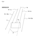
ただし、基準角度範囲は、必ずしも1つの走査角度に対応させる必要はなく、検出したい範囲が多き場合には、例えば図4に示すように、走査角度(N-Δ)、走査角度(N)、走査角度(N+Δ)の複数の走査角度にまたがって設定することができる。そのため、本明細書では、1つの走査角度に対応するものも複数の走査角度に対応するものも総称して、基準角度範囲としている。なお、Nは角度、Δは角度分解能を意味している。つまり、基準角度範囲は、検出対象の大きさに基づいて設定することができる。 However, the reference angle range does not necessarily have to correspond to one scan angle, and when the range to be detected is large, it can be set across multiple scan angles, for example, scan angle (N-Δ), scan angle (N), and scan angle (N+Δ), as shown in FIG. 4. For this reason, in this specification, the reference angle range is used to collectively refer to both those corresponding to one scan angle and those corresponding to multiple scan angles. Note that N means angle, and Δ means angular resolution. In other words, the reference angle range can be set based on the size of the detection target.
その一方で、基準角度範囲は、基準物40の物理的な大きさに基づいて設定することもできる。例えば図4に物理的設定例として示しているように、基準物40の大きさが走査角度(N-Δ~N+Δ)にまたがっている場合には、基準角度範囲を走査角度(N-Δ~N+Δ)に設定することができる。
On the other hand, the reference angle range can also be set based on the physical size of the
あるいは、基準物40の物理的な大きさによらず、論理的に設定することもできる。例えば図5に論理的構成例として示すように、基準物40が物理的に走査角度(N-2Δ~N+2Δ)の大きさである場合、走査角度(N-Δ~N+Δ)の範囲のデータだけを抽出することによって、基準角度範囲を走査角度(N-Δ~N+Δ)に論理的に設定することができる。
Alternatively, it can be set logically regardless of the physical size of the
また、放射光6が放射される範囲やその直径は計算により求めることができるため、検出対象となる物体に合わせた大きさや位置に基準物40を設け、その基準物40を検出できる範囲を基準角度範囲に設定することもできる。
In addition, since the range and diameter of the emitted
次に、上記した構成の作用について説明する。
上記したように、レーザ距離計測装置1は、対象空間に放射さした放射光6の反射光7を受光することにより、物体の距離と方位とを検出する。このとき、例えば図6に検出可能状態として示すように、対象空間に人が存在するような場合には、衣服によって放射光6が散乱し、その一部が反射光7としてレーザ距離計測装置1に向かって反射することにより、人を物体として検出することができる。なお、図6および図8等では、放射光6の経路をわかり易くするために、経路を分けて図示している。
Next, the operation of the above-mentioned configuration will be described.
As described above, the laser
ただし、前述のように、レーザ距離計測装置1は、その計測原理上、反射光7を受光できなかったり反射光7のレベルが低すぎてノイズに紛れてしまったりすることによって検出が困難になる物体が想定される。例えば、図6に検出不可状態その1として示すように、黒い車両やコーティング塗装された車両の場合、その表面が鏡面となって放射光6が他の方向に反射してしまい、検出が困難になるおそれがある。あるいは、図6に検出不可状態その2として示すように、車両の表面が曲面状の場合には、放射光6が走査平面Xからずれた方向に反射してしまい、検出が困難になるおそれがある。
However, as mentioned above, due to the measurement principle of the laser
ところで、想定する対象空間によっては、必ずしも距離の計測が求められない状況も想定される。例えば、侵入者の有無が検知できればよい場合や、本実施形態で想定している踏切であれば踏切を横断している物体の有無を検知できればよい場合などである。なお、距離の計測が不要という意味ではなく、物体の有無を検出することのほうが重要になる状況が想定されるという意味である。 However, depending on the assumed target space, there may be situations where measuring distance is not necessarily required. For example, there may be cases where it is sufficient to detect the presence or absence of an intruder, or, in the case of the railroad crossing assumed in this embodiment, there may be cases where it is sufficient to detect the presence or absence of an object crossing the railroad crossing. Note that this does not mean that measuring distance is unnecessary, but rather that there may be situations where it is more important to detect the presence or absence of an object.
そこで、本実施形態では、物体の有無を検出することを主眼として、レーザ距離測定装置に基準物判定部32と物体判定部33を設け、図7に示す物体検出処理を実行する。なお、図7に示す物体検出処理は制御部20や測距部31なども関与しているため、以下では、説明の簡略化のためにレーザ距離測定装置を主体にして説明する。
Therefore, in this embodiment, the main focus is on detecting the presence or absence of an object, and a reference
レーザ距離測定装置は、図7に示す物体検出処理において、ステップS1において測距を行う。このステップS1の処理は、測距部31によって走査角度ごとに行われる。続いて、レーザ距離測定装置は、ステップS2において、現在の走査角度が基準角度範囲であるかを判定する。レーザ距離測定装置は、基準角度範囲でないと判定した場合には、ステップS2においてNOとなることから、次の走査角度での測距を行う。
In the object detection process shown in FIG. 7, the laser distance measuring device performs distance measurement in step S1. This process of step S1 is performed for each scanning angle by the
一方、レーザ距離測定装置は、基準角度範囲であると判定した場合には、ステップS2においてYESとなることから、ステップS3において基準物40を検出できたかを判定する。このステップS2の処理は、基準物判定部32によって行われる。
On the other hand, if the laser distance measuring device determines that it is within the reference angle range, the result is YES in step S2, and it then determines in step S3 whether the
このとき、レーザ距離計測装置1は、測距部31の計測結果に基づいて、基準角度範囲(α)において所定の基準距離(L)に物体が検出された場合に基準物40が検出できたと判定する。なお、基準角度範囲が複数の走査角度にまたがっている場合には、基準角度範囲に含まれる走査角度における物体の検出結果を記憶しておき、基準角度範囲に含まれる全ての走査角度において物体が検出されたときに基準物40が検出できたと判定される。
At this time, the laser
例えば、図8に判定態様その1として示すように、レーザ距離計測装置1と基準物40との間に他の物体が存在しない場合、放射光6は基準物40で反射することになる。そのため、この場合には、基準角度範囲(α)において所定の基準距離(L)に物体、ここでは基準物40が検出されたことになる。そのため、レーザ距離計測装置1は、基準物40が検出されたことから、つまりは、レーザ距離計測装置1と基準物40との間に他の物体が存在しないことから、ステップS3においてYESとなり、ステップS1に移行して次の走査角度に対して測距を行う。
For example, as shown in FIG. 8 as
これに対して、図8に判定態様その2として示すように基準物40との間に車両が存在している場合には、放射光6が車両によって遮られることになる。この場合、レーザ距離計測装置1は、車両で反射した反射光7が検出できるか否かに関わらず、基準角度範囲(α)において所定の基準距離(L)に物体が検出されることはない。そのため、レーザ距離計測装置1は、基準物40を検出できないと判定する。そして、この状況は、基準物40との間に他の物体が存在していることを示している。
In contrast, when a vehicle is present between the
そのため、レーザ距離計測装置1は、ステップS3においてNOとなった場合には、ステップS4において物体ありと判定し、ステップS5において物体あり信号を例えば管理装置25に対して出力して処理を終了する。なお、物体検出処理の流れを説明するために処理を終了しているが、実際には、信号を出力した後にステップS1に移行して次の測距を行っている。
このような流れでレーザ距離計測装置1は、物体の有無を判定している。
Therefore, if the result in step S3 is NO, the laser
In this manner, the laser
ところで、基準物40は、レーザ距離計測装置1の検出対象となる対象空間に設置されている。そして、その対象空間は屋外であることが想定され、レーザ距離測定装置も、屋外に設置されることが想定される。その場合、基準物40に泥やゴミなどが付着したり、基準物40が損傷したりすると、放射光6が反射されずに物体ありとご認識するおそれがある。
The
そこで、レーザ距離計測装置1は、図9に示す異常判定処理を実行している。なお、この処理は、異常判定部34によって実行されている。ただし、図7に示す物体検出処理と一部共通する処理が含まれているため、図7に示す物体検出処理のステップS3においてNOとなったとき、あるいは、ステップS4において物体検出信号を出力する際に呼び出されるサブルーチンとして実装することもできる。
The laser
レーザ距離計測装置1は、図9に示す異常判定処理のステップS11において測距を実行し、ステップS12において現在の走査角度が基準範囲角度であるかを判定する。レーザ距離計測装置1は、現在の走査角度が基準範囲角度でない場合には、ステップS12においてNOとなることから、ステップS11に移行する。
The laser
一方、レーザ距離計測装置1は、現在の走査角度が基準範囲角度である場合には、ステップS12においてYESとなることから、基準物40を検出できたかを判定する。ここまでの処理は、基本的に図7に示す物体検出処理と共通する態様で実行される。
On the other hand, if the current scanning angle is within the reference range angle, the laser
そして、レーザ距離計測装置1は、基準物40を検出できた場合には、ステップ13においてYESとなることから、ステップS18において経過時間をクリアして処理を終了する。この経過時間は、以下に説明する様に、以前に基準物40を検出できなかったと判定した時点から経過した時間であり、異常の有無の判定に用いられる。つまり、レーザ距離計測装置1は、ステップS18において、基準物40が検出できた場合には異常がないと判定して経過時間をクリアしている。
If the laser
これに対して、レーザ距離計測装置1は、基準物40を検出できなかった場合には、ステップ13においてNOとなることから、ステップS14に移行して、以前に検出できなかったと判定してからの経過時間を取得する。なお、以前の判定時には基準物40が検出できていた場合には、経過時間がクリアされているため、経過時間のカウントが開始されることになる。
In contrast, if the laser
続いて、レーザ距離計測装置1は、ステップS15において、経過時間が予め設定されている異常判定時間を超えたかを判定し、経過時間が異常判定時間を超えていない場合には、ステップS15においてNOとなることから、ステップS11に移行して次の測距を行う。この場合、経過時間はクリアされずに継続してカウントされ、経過時間の累積値が次回以降の判定に用いられる。この異常判定時間は、適宜設定することができるが、本実施形態のように例えば踏切を想定している場合には、踏切を移動すると想定される物体である人や車両の一般的な速度を考慮して例えば1分程度に設定することができる。あるいは、異常判定時間は、例えば5回や10回といった走査回数に要する時間として定義することもできる。
Then, in step S15, the laser
これに対して、レーザ距離計測装置1は、何回かの判定を経て経過時間が異常判定時間を超えた場合には、ステップS15においてYESとなることから、ステップS16において異常と判定し、ステップS17において異常検知信号を出力して処理を終了する。
In contrast, if the elapsed time exceeds the abnormality determination time after several determinations, the laser
この異常としては、例えば、外的な力が加わったことによるレーザ距離計測装置1の向きのずれ、外的な力が加わったことによる基準物40の向きや位置のずれあるいは破損、基準物40にゴミや泥などが付着した状態、レーザ距離計測装置1自体が故障した状態などが考えられる。ただし、物体の有無の判定だけでは異常の原因を特定することは困難であるため、レーザ距離計測装置1は、異常検知信号を出力することによって、異常が検知されたことを報知する。
Such abnormalities may include, for example, a shift in the orientation of the laser
このように、レーザ距離計測装置1は、所定の基準角度範囲に設けられている基準物40を検出できたか否かに基づいて、物体の有無を検出している。
In this way, the laser
以上、説明したレーザ距離計測装置1によれば、次のような効果を得ることができる。
レーザ距離計測装置1は、レーザ光を発生させてから反射光7が受光されるまでの時間に基づいて対象空間内に存在する物体までの距離および方位を計測するとともに、その計測結果に基づいて対象空間内の予め定められた位置に設けられている基準物40の有無を判定する。これにより、レーザ距離計測装置1は、低反射物や物体の表面形状などによって仮に距離の計測ができなかったとしても、基準物40との間に物体が存在するか否かを判定することができる。したがって、検出が困難な物体の検出が可能になる。
According to the laser
The laser
また、レーザ距離計測装置1は、物体が検出できたか否かに基づいて、予め定められている異常判定時間を超えて物体があると継続して判定されている場合には、異常があると判定する。これにより、例えば踏切内での立ち往生の検出や、基準物40の故障や汚れ、あるいはレーザ距離計測装置1または基準物40の向きがずれた位置ずれなどの異常を検出することができる。
In addition, the laser
本実施形態では走査角度ごとに判定する例を示したが、各走査角度における物体の検出結果を記憶しておき、1回の走査が完了した時点で移動方向を判定する構成とすることができる。 In this embodiment, an example is shown in which a judgment is made for each scanning angle, but it is also possible to store the object detection results for each scanning angle and determine the direction of movement when one scan is completed.
(第2実施形態)
以下、第2実施形態につて説明する。本実施形態のレーザ距離計測装置1は、基本的には第1実施形態と共通する構成であり、第1実施形態と同様に、所定の基準角度範囲に設けられている基準物40を検出できたか否かに基づいて物体の有無を検出している。そして、本実施形態では、第1実施形態による物体の検出を拡張した態様で、物体の移動方向を判定する。
Second Embodiment
The second embodiment will be described below. The laser
本実施形態では、対象空間(S)として、図10に矢印にて示すように進行方向が規定されている場所、例えば一方通行の道路や高速道路への誘導路などを想定している。この対象空間には、移動方向を判定するための複数の基準物40が設けられている。本実施形態の場合、基準角度範囲がα1、α2およびα3となる位置に、少なくとも3つの基準物40がそれぞれ設けられている。このとき、α1、α2およびα3は、一方通行の道路や高速道路への逆走による車両の侵入の検知することを想定し、一般的な例えば乗用車のような車両の大きさに基づいて、車両が通過する際に全ての基準物40が同時に覆われる状態が発生する位置に設定されている。
In this embodiment, the target space (S) is assumed to be a place where the direction of travel is specified, such as a one-way road or a taxiway leading to a highway, as shown by the arrow in FIG. 10. In this target space, multiple reference objects 40 are provided to determine the direction of travel. In this embodiment, at least three
ただし、移動方向を判定する場合には、複数つまりは2以上の基準物40を設ければよい。また、基準物40は、それぞれの基準角度範囲に対して1つずつ設けることができるが、第1実施形態で説明したように論理的に複数の基準角度範囲を設定できる大きさのものを1つ設けたり、1つの基準角度範囲を設定可能な大きさのものと複数の基準角度範囲を設定可能な大きさものとを混在させたりすることができる。
However, when determining the direction of movement, it is sufficient to provide multiple reference objects 40, i.e., two or more. Also, one
また、基準物40を複数設ける場合は、各基準物40をコンパクトにできることから、設置が容易になるという利点がある。一方、例えば既設の壁面等に再帰反射テープなどを敷設して基準物40を設ける場合には、設置スペースが不要になるといった利点がある。
In addition, when multiple reference objects 40 are provided, each
そして、レーザ距離計測装置1は、図11に示すように移動方向判定部35を備えている。この移動方向判定部35は、制御部20でプログラムを実行することによってソフトウェアで実現されており、物体判定部33の判定結果に基づいて物体の移動方向を判定する。
The laser
そして、レーザ距離計測装置1は、図12に示す移動方向判定処理を実行する。なお、図12では説明の簡略化のために物体の有無を判定するまでの処理を省略しているが、物体の有無は、図7に示す物体検出処理と同様の流れで判定することができる。そのため、移動方向検出処理は、図7に示す物体検出処理のステップS3においてNOとなったとき、あるいは、ステップS4において物体検出信号を出力する際に呼び出されるサブルーチンとして実装することもできる。
Then, the laser
さて、レーザ距離計測装置1は、ステップS21において物体の有無を判定しており、物体なしと判定した場合には、ステップS21においてNOとなることから、ステップS21の判定を繰り返す。
Now, the laser
一方、レーザ距離計測装置1は、物体ありと判定した場合には、ステップS21においてYESとなることから、ステップS22において物体ありと判定された基準角度範囲と、判定した時刻とを記憶する。例えば、図13に時刻t1として示すように、時刻t1においてα1の位置に物体が検出された場合、レーザ距離計測装置1は、基準角度範囲としてα1、最初に物体が検出された時刻としてt1を例えばRAMにデータとして記憶する。
On the other hand, if the laser
続いて、レーザ距離計測装置1は、ステップS23において、隣り合う位置のデータがあるかを判定する。つまり、レーザ距離計測装置1は、α1に隣り合う基準角度範囲であるα2のデータが記憶されているかを判定する。図13の場合、車両がα1からα2に向かって移動しているため、α2の位置のデータは記憶されていない状態になっている。そのため、レーザ距離計測装置1は、隣り合う位置のデータがないと判定し、ステップS23においてNOとなることから、ステップS21に移行する。
Then, in step S23, the laser
さて、レーザ距離計測装置1は、図13に時刻t2として示すように、時刻t1においてα1の位置に物体が検出された状態で、時刻t2においてα2の位置に物体が検出された場合には、ステップS21においてYESとなることから、ステップS22において基準角度範囲としてα2、最初に検出された時刻としてt2をデータとして記憶する。
Now, as shown as time t2 in FIG. 13, if an object is detected at the position α1 at time t1 and then an object is detected at the position α2 at time t2, the result in step S21 becomes YES, and in step S22, the laser
この場合、レーザ距離計測装置1は、α1のデータが記憶されていることから、ステップS23においてYESとなり、ステップS24において移動判定時間内であるかを判定する。この移動判定時間は、想定される物体の速度に基づいて設定することができ、例えば磁束40km程度で走行している車両が基準物40の前を通るのに要する時間に基づいて設定され、人を検出する場合には人の歩行速度に応じて設定される。
In this case, since the data of α1 is stored, the laser
そして、レーザ距離計測装置1は、ステップS24において、α1の位置で物体が検出された時刻t1とα2の位置で物体が検出された時刻t2と差分が、移動判定時間内であるかを判定する。つまり、レーザ距離計測装置1は、ステップS24では、移動方向の判定を正しく行える状態であるか否かを検証している。
Then, in step S24, the laser
レーザ距離計測装置1は、移動判定時間内でないと判定した場合には、ステップS24においてNOとなることから、ステップS28においてデータをクリアして終了する。なお、ここでは説明の簡略化のために便宜的に処理を終了するとしているが、実際には、データをクリアした後にステップS21に移行して物体があるかの判定を繰り返している。
If the laser
これに対して、レーザ距離計測装置1は、移動判定時間内であると判定した場合には、ステップS24においてYESとなることから、ステップS25において移動方向を判定する。この場合、レーザ距離計測装置1は、α1の位置のデータが記憶されている状態でα2の位置に物体あると判定されたことから、その判定された順番に基づいて、物体がα1からα2への向きに移動していると判定する。
In contrast, if the laser
そして、レーザ距離計測装置1は、ステップS26において、判定した移動方向を示す移動方向信号を出力する。この場合、移動方向信号は、単に移動方向を報知する信号としてもよいが、移動方向から逆走であると判定できた場合には、逆走を報知する逆走信号を出力したり、第1実施形態で説明した異常判定処理と組み合わせて逆走を異常とみなして異常検出信号を出力したり、逆走した方向に設けた警告灯などを作動させることができる。
Then, in step S26, the laser
その後、レーザ距離計測装置1は、ステップS27において記憶しているデータをクリアして終了する。なお、ここでは説明の簡略化のために便宜的に処理を終了するとしているが、実際には、データをクリアした後にステップS21に移行して物体があるかの判定を繰り返す。なお、図13に時刻t3として示すように、時刻3においてα3の位置に物体が検出された場合には、記憶がクリアされていることから、重複して移動方向信号を出力することはない。つまり、移動方向を正しく判定できる状態になる。
Then, the laser
このように、レーザ距離計測装置1は、基準物40が検出できるか否かに基づいて物体の有無を判定し、物体の有無の判定結果に基づいて、検出された物体の移動方向を判定している。
In this way, the laser
以上、説明したレーザ距離計測装置1によれば、次のような効果を得ることができる。
レーザ距離計測装置1は、レーザ光を発生させてから反射光7が受光されるまでの時間に基づいて対象空間内に存在する物体までの距離および方位を計測するとともに、その計測結果に基づいて対象空間内の予め定められた位置に設けられている基準物40の有無を判定し、その判定結果に基づいて予め定められた位置に設けられている基準物40を検出できるか否かを判定し、その判定結果に基づいて物体の移動方向を判定する。
According to the laser
The laser
このとき、レーザ距離計測装置1は、基準物40は対象空間内に複数設けられており、それら複数の基準物40との間の物体の有無をそれぞれ判定し、物体があると判定された順番に基づいて物体の移動方向を判定する。
At this time, the laser
このような構成とすることにより、レーザ距離計測装置1は、まず、検出が困難な物体の検出が可能になるとともに、その物体の移動方向を判定することができるとともに、例えば踏切内での人や車両の進行方向を検出することができ、また、例えば一方通行の道路や高速道路への誘導路への逆走などを検出することができる。
With this configuration, the laser
また、移動方向判定処理と第1実施形態で説明した異常判定処理とを組み合わせることができる。これにより、例えば踏切内での立ち往生などを検出することができる。 The movement direction determination process can also be combined with the abnormality determination process described in the first embodiment. This makes it possible to detect, for example, a vehicle being stuck at a railroad crossing.
また、本実施形態では走査角度ごとに判定する例を示したが、各走査角度における物体の検出結果を記憶しておき、1回の走査が完了した時点で移動方向を判定する構成とすることができる。 In addition, in this embodiment, an example of determining for each scanning angle is shown, but it is also possible to store the object detection results for each scanning angle and determine the direction of movement when one scan is completed.
最初に物体が検出された基準角度範囲と隣り合っていない別の基準角度範囲で物体が検出された場合、物体が複数あると判定することができる。その場合、距離が計測できれば距離に基づいて移動方向を個別に判定することができる。なお、複数の物体が検出された場合には、移動方向の判定や後述する第3実施形態で説明する人の識別を行わない構成とすることができる。 If an object is detected in a different reference angle range that is not adjacent to the reference angle range in which the object was first detected, it can be determined that there are multiple objects. In this case, if the distance can be measured, the direction of movement can be determined individually based on the distance. Note that if multiple objects are detected, the configuration can be such that the direction of movement is not determined and the person is not identified, as described in the third embodiment below.
また、隣り合う状態で少なくとも3つ以上設けられている基準物40との間の物体の有無を判定することにより、例えば中央の基準物40についてのみ物体ありと判定され、他の基準物40との間に物体なしと判定された場合には、基準物40の大きさに基づいて、物体の大きさを判定することができる。
In addition, by determining the presence or absence of an object between at least three or more reference objects 40 that are provided adjacent to each other, if it is determined that an object is present only for the
(第3実施形態)
以下、第3実施形態について説明する。本実施形態のレーザ距離計測装置1は、基本的には第1実施形態と共通する構成であり、第1実施形態と同様に、所定の基準角度範囲に設けられている基準物40を検出できたか否かに基づいて物体の有無を検出している。そして、本実施形態では、第1実施形態による物体の検出を拡張した基本的な識別態様で、また、第2実施形態による移動方向の判定を拡張した応用的な識別態様で、検出された物体が人であるかを識別する。
Third Embodiment
The third embodiment will be described below. The laser
本実施形態では、図14に示すように、対象空間(S)として、人と車両などの人以外の物体とが混在する例えば踏切を想定している。この対象空間には、少なくとも3つ以上の複数の基準物40が設けられている。本実施形態の場合、基準角度範囲がα11、α12およびα13となる位置にそれぞれ基準物40が設けられている。 In this embodiment, as shown in FIG. 14, the target space (S) is assumed to be, for example, a railroad crossing in which people and non-human objects such as vehicles coexist. At least three or more reference objects 40 are provided in this target space. In this embodiment, the reference objects 40 are provided at positions where the reference angle ranges are α11, α12, and α13.
これらの基準物40は、それぞれの基準角度範囲に対して1つずつ設けることができるが、第1実施形態で説明したように論理的に複数の基準角度範囲を設定できる大きさのものを1つ設けたり、1つの基準角度範囲を設定可能な大きさのものと複数の基準角度範囲を設定可能な大きさものとを混在させたりすることができる。 One of these reference objects 40 can be provided for each reference angle range, but as described in the first embodiment, it is possible to provide one that is large enough to logically set multiple reference angle ranges, or to mix one that is large enough to set one reference angle range with one that is large enough to set multiple reference angle ranges.
また、基準物40は、レーザ距離計測装置1から見た状態において、所定の大きさおよび間隔となるように設けられている。なお、レーザ距離計測装置1から見た状態においてとは、レーザ距離計測装置1から見た見かけ上の大きさは距離に応じて変わることから、基準物40が設置されている位置において、以下に述べるそれぞれの幅が確保される状態を意味している。
The reference objects 40 are also set to have a predetermined size and spacing when viewed from the laser
具体的には、図15に人識別状態として示すように、α11の位置に対応する基準物40は、その幅がW1となるように設けられ、α12の位置に対応する基準物40は、その幅がW2となるように設けられ、α13の位置に対応する基準物40は、その幅がW3となるように設けられている。このとき、中央の基準物40の幅W2は、一般的な人の例えば胴体の幅程度、つまりは、人を識別するために例えば40cm程度の大きさとなるように設けられている。他の基準物40の幅はとくに限定する必要はないものの、本実施形態ではW1およびW3は、W2よりも小さい幅にしている。
Specifically, as shown in FIG. 15 as a person identification state, the
また、基準物40は、他の基準物40との間の幅がそれぞれW11、W12となるように設けられている。このとき、幅W11および幅W12は、幅W2よりも大きく形成されている。換言すると、複数の基準物40が人によって同時に覆われることがない幅が設定されている。 The reference objects 40 are also set so that the widths between them and other reference objects 40 are W11 and W12, respectively. At this time, widths W11 and W12 are formed larger than width W2. In other words, a width is set so that multiple reference objects 40 are not covered by people at the same time.
以下、人を識別するための大きさに形成されていて、両隣の基準物40との間が同時に覆われることがない幅となっている基準物40を、便宜的に識別用の基準物40と称する。
Hereinafter, for the sake of convenience, a
また、基準物40は、α11の位置の基準物40からα13の位置の基準物40までの幅がWとなるように設けられている。これは、図5に車両識別状態として示すように車両の識別をも可能とするためである。そのため、幅Wは、一般的な車両の全長よりも短くなるように、換言すると、全ての基準物40が同時に車両によっておおわれる状態が発生するように設けられている。
The reference objects 40 are also arranged so that the width from the
そして、レーザ距離計測装置1は、図16に示すように、人識別部36を備えている。この人識別部36は、制御部20でプログラムを実行することによってソフトウェアで実現されており、物体があると判定された際、隣り合う基準物40との間の物体の有無に基づいて、物体が人であるか否かを識別する。
The laser
<基本的な識別態様の例>
以下、基本的な識別態様の例について説明する。基本的な識別態様の例では、レーザ距離計測装置1は、図17に示す人識別処理その1を実行する。なお、図17では説明の簡略化のために物体の有無を判定するまでの処理を省略しているが、物体の有無は、図7に示す物体検出処理と同様の流れで判定することができる。そのため、人識別処理その1は、図7に示す物体検出処理のステップS3においてNOとなったとき、あるいは、ステップS4において物体検出信号を出力する際に呼び出されるサブルーチンとして実装することもできる。
<Examples of basic identification patterns>
An example of a basic identification mode will be described below. In the example of the basic identification mode, the laser
レーザ距離計測装置1は、ステップS31において物体ありと判定した場合には、ステップS31においてYESとなることから、ステップS32において、識別用の基準物40との間であるかを判定する。レーザ距離計測装置1は、物体ありと判定されたのが識別用の基準物40との間ではない場合には、ステップS32においてNOとなることから、ステップS31に移行して判定を繰り返す。
If the laser
一方、レーザ距離計測装置1は、物体ありと判定されたのが識別用の基準物40との間である場合には、ステップS32においてYESとなることから、ステップS33において、隣り合う他の基準物40との間に物体が検出されているかを判定する。これは、図15に示したように、識別用の基準物40との間に物体が検出されたとしても、隣り合う基準物40との間にも物体が検出されている場合には、人ではないと考えられるためである。
On the other hand, if the laser
そのため、レーザ距離計測装置1は、隣り合う他の基準物40との間に物体が検出されていると判定した場合には、ステップS33においてYESとなることから、ステップS34において検出された物体が人ではないと判定して終了する。なお、ここでは説明の簡略化のために便宜的に処理を終了するとしているが、実際にはステップS31に移行して物体があるかの判定を繰り返す。
Therefore, if the laser
一方、レーザ距離計測装置1は、隣り合う他の基準物40との間に物体が検出されていないと判定した場合には、ステップS33においてNOとなることから、ステップS35において検出された物体が人であると判定し、ステップS36において人を識別したことを示す人識別信号を出力して終了する。なお、ここでは説明の簡略化のために便宜的に処理を終了するとしているが、実際にはステップS31に移行して物体があるかの判定を繰り返す。
On the other hand, if the laser
このように、レーザ距離計測装置1は、物体があると判定された際、隣り合う他の基準物40との間の物体の有無に基づいて、物体が人であるか否かを識別している。
In this way, when the laser
<応用的な識別態様の例>
以下、応用的な識別態様の例について説明する。応用的な識別態様の例では、レーザ距離計測装置1は、図18に示す人識別処理その2を実行する。この応用的な識別態様の例では、複数回の走査が行われた状態で実行されるものである。なお、図18では説明の簡略化のために物体の有無を判定するまでの処理を省略しているが、物体の有無は、図7に示す物体検出処理と同様の流れで判定することができる。そのため、人識別処理その2は、図7に示す物体検出処理のステップS3においてNOとなったとき、あるいは、ステップS4において物体検出信号を出力する際に呼び出されるサブルーチンとして実装することもできる。
<Examples of applied identification modes>
An example of an applied identification mode will be described below. In the example of the applied identification mode, the laser
レーザ距離計測装置1は、ステップS41において、物体があるかを判定しており、物体がないと判定した場合には、ステップS41においてNOとなることから判定を繰り返す。一方、レーザ距離計測装置1は、物体がありと判定した場合には、ステップS41においてYESとなることから、ステップS42において、全ての基準角度範囲のデータがあるかを判定する。このデータは、物体ありと判定された基準角度範囲と最初に判定された時刻である。
In step S41, the laser
より詳細には、レーザ距離計測装置1は、ステップS42では、現時点から所定の移動判定時間だけ遡った期間内に、本実施形態であればα11の位置、α12の位置、およびα13の位置のデータが記憶されているかを判定している。以下、現時点から移動判定時間だけ遡った期間を、便宜的に判定期間と称する。また、移動判定時間は、第2実施形態で説明したように予め設定されている。
More specifically, in step S42, the laser
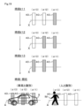
例えば図19に示すように、ある時刻t11において基準角度範囲がα11の位置に物体があると判定され、α12の位置とα13の位置では物体なしと判定されたとする。なお、図19では、判定期間内に物体ありと判定された基準角度範囲に設けられている基準物40に斜線のハッチングを付している。
For example, as shown in FIG. 19, assume that at a certain time t11, it is determined that an object is present at the reference angle range position α11, and that no object is present at positions α12 and α13. Note that in FIG. 19, the
この場合、レーザ距離計測装置1は、データが記憶されていない基準角度範囲があることから、ステップS42においてNOとなり、ステップS41に移行して物体の判定を繰り返す。その後、図19に示す時刻t12においてα12の位置で物体ありと判定されたとしても、α13の位置では物体なしと判定されているため、物体の判定が繰り返される。
In this case, since there is a reference angle range for which no data is stored, the laser
そして、時刻t13においてα12の位置で物体ありと判定されたとすると、レーザ距離計測装置1は、全ての基準角度範囲のデータが記憶されていることから、ステップS42においてYESとなり、各基準角度範囲で物体が検出された時刻に基づいて、その物体の移動方向を判定する。換言すると、レーザ距離計測装置1は、ステップS43において、検出された物体が移動体であることを検証している。
If it is determined that an object is present at position α12 at time t13, the laser
この場合、時系列では時刻t11にα11の位置、時刻t12にα12の位置、時刻t13にα13の位置で物体ありと判定されていることから、レーザ距離計測装置1は、α11からα13への図示左方の向きに物体が移動したと判定する。そして、レーザ距離計測装置1は、ステップS44において、現在時刻つまりは時刻t13において、全ての基準物40との間に物体があるかを判定する。
In this case, since it is determined in the time series that an object is present at position α11 at time t11, at position α12 at time t12, and at position α13 at time t13, the laser
このとき、各基準物40は、上記したように人を識別可能な大きさと間隔で設けられている。また、各基準物40は、上記したように車両を識別可能な大きさと間隔で設けられている。そのため、図19に時刻現在として示しているように、現在時刻で全ての基準物40との間に物体ありと判定されている場合には、その物体は車両であると判定することができる。また、現在時刻で1つの基準物40との間に物体ありと判定されている場合には、その物体は人であると判定することができる。なお、図19では、現在時刻で物体ありと判定されている基準物40に横線のハッチングを付している。
At this time, as described above, each
このため、レーザ距離計測装置1は、全ての基準物40との間に物体があると判定した場合には、ステップS44においてYESとなることから、ステップS45において物体が車両であると判定し、ステップS46において車両を識別したことを示す車両識別信号を出力する。
Therefore, if the laser
一方、レーザ距離計測装置1は、1つの基準物40との間に物体があると判定した場合には、ステップS44においてNOとなることから、ステップS47において物体が人であると判定し、ステップS48において人を識別したことを示す人識別信号を出力する。
On the other hand, if the laser
このように、レーザ距離計測装置1は、物体があると判定された際、隣り合う他の基準物40との間の物体の有無に基づいて、物体が人であるか車両であるかを識別している。
以上説明したレーザ距離計測装置1によれば、次のような効果を得ることができる。
In this way, when the laser
According to the laser
レーザ距離計測装置1は、レーザ光を発生させてから反射光7が受光されるまでの時間に基づいて対象空間内に存在する物体までの距離および方位を計測するとともに、その計測結果に基づいて対象空間内の予め定められた位置に設けられている基準物40の有無を判定し、その判定結果に基づいて予め定められた位置に設けられている基準物40を検出できるか否かを判定し、その判定結果に基づいて、複数の基準物40との間の物体の有無をそれぞれ判定し、隣り合う基準物40との間の物体の有無に基づいて、物体が人であるか否かを識別する。
The laser
これにより、レーザ距離計測装置1は、まず、検出が困難な物体の検出が可能になるとともに、その物体の移動方向を判定することができるとともに、例えば進入が禁止されている範囲への人や車両の侵入などを検出することができる。
As a result, the laser
また、レーザ距離計測装置1は、隣り合う状態で少なくとも3つ以上設けられている基準物40との間の物体の有無を判定する。これにより、例えば中央の基準物40についてのみ物体ありと判定され、他の基準物40との間に物体なしと判定された場合には、基準物40の大きさに基づいて、物体の大きさを判定することができる。
The laser
また、レーザ距離測定装置は、隣り合う状態で設けられ、少なくとも1つが人の胴体よりも小さくなるように設けられているとともに、隣り合う基準物40との間が人の胴体より大きく設けられている複数の基準物40との間の物体の有無を判定する。これにより、検出された物体が人であるか否かを判定することができる。 The laser distance measuring device determines the presence or absence of an object between a plurality of reference objects 40 that are arranged side by side, at least one of which is smaller than a human torso, and the distance between adjacent reference objects 40 is larger than a human torso. This makes it possible to determine whether the detected object is a human or not.
また、人識別処理その1や人識別処理その2は、第1実施形態で説明した異常判定処理と組み合わせることができる。例えば人や車両を識別できた状態で、人や車両が異常判定時間を経過しても移動していない場合には、立ち往生であるとして異常ここでは危険を報知するために異常検出信号を出力することができる。
Furthermore, the
また、実施形態では基準物40を設置する際の幅Wとして車両を識別できる大きさに設定する例を示したが、自転車や自動二輪車を識別できる大きさに設定することができる。これにより、車両ほどの大きさではない自転車や自動二輪などを識別することができる。また、対象空間に、人を識別するための基準物40、車両を識別するための基準物40、自転車や自動二輪車を識別するための基準物40を個別に設ける構成とすることができる。
In the embodiment, the width W of the
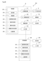
(その他の実施形態)
各実施形態ではレーザ距離計測装置1に各判定部や識別部を設ける構成を例示したが、例えば図20に示すように、基準物判定部32、物体判定部33、異常判定部34、移動方向判定部35、人識別部36は、その全部あるいは一部を管理装置25に設ける構成、あるいは、レーザ距離計測装置1との双方に設ける構成とすることができる。
Other Embodiments
In each embodiment, a configuration has been illustrated in which each judgment unit and identification unit is provided in the laser
このようなレーザ距離計測装置1と管理装置25とにより構成される物体検出システム50によっても、検出が困難な物体の検出を可能になるなど、各実施形態で説明したレーザ距離計測装置1と同様の効果を得ることができる。また、管理装置25のアプリケーションソフトウェアとして実装することにより、既設のレーザ距離計測装置1に対しても実施形態で説明した各機能を容易に適用することができる。
The
実施形態では基準角度範囲を固定値とする例を示したが、物体との距離が検出できた場合には、物体までの距離に応じて基準角度範囲を変更する構成とすることができる。例えば、検出された物体までの距離が相対的に遠ければ基準角度範囲に含める走査角度を増やし、距離が相対的に近ければ基準角度範囲に含める走査角度を減らすことができる。これにより、レーザ距離計測装置1から見た場合の相対的な大きさが距離によって変化する状況において、物体の検出や識別の精度を向上させることができる。
In the embodiment, an example was shown in which the reference angle range was a fixed value, but if the distance to an object can be detected, the reference angle range can be changed according to the distance to the object. For example, if the distance to the detected object is relatively far, the scanning angle included in the reference angle range can be increased, and if the distance is relatively close, the scanning angle included in the reference angle range can be decreased. This makes it possible to improve the accuracy of object detection and identification in a situation in which the relative size as seen from the laser
基準角度範囲以外のデータを参照する構成とすることができる。すなわち、基準物40が対象空間内に隣り合うように所定の間隔で複数設けられており、それら複数の基準物40との間に物体があると判定された際、基準物40との間以外における物体の検出結果に基づいて、物体が複数の人であるか、または、人と人以外の物体であるかを識別する構成とすることができる。この識別は、物体判定部33または人識別部36により行うことができる。
It is possible to configure the system to refer to data outside the reference angle range. In other words, a plurality of reference objects 40 are provided adjacent to each other at a predetermined interval in the target space, and when it is determined that an object exists between the plurality of reference objects 40, it is possible to configure the system to identify whether the object is a plurality of people, or a person or an object other than a person, based on the detection result of the object other than between the reference objects 40. This identification can be performed by the
例えば、人は、衣服でレーザ光が散乱することから、対象区間内であれば基準角度範囲外であっても検出することができる。そのため、基準角度範囲外で検出された物体の移動軌跡を記憶しておき、複数人が同時期に基準角度範囲に進入した場合には、移動軌跡のデータを加味して、移動方向の判定や人であるか否かの識別を行う構成とすることができる。これにより、複数の物体が存在することが想定される状況において、複数の人が検出されたのか、人と人以外の物体例えば車両が検出されたのかを判定することができる。 For example, because laser light is scattered by clothing, people can be detected even if they are outside the reference angle range as long as they are within the target section. For this reason, the movement trajectory of an object detected outside the reference angle range can be stored, and if multiple people enter the reference angle range at the same time, the movement trajectory data can be taken into account to determine the direction of movement and identify whether or not they are people. In this way, in a situation where the presence of multiple objects is expected, it can be determined whether multiple people have been detected, or whether a person or an object other than a person, such as a vehicle, has been detected.
図面中、1はレーザ距離計測装置、3はレーザ光発生部、4は受光部、11は回転ミラー(反射部)、12は駆動部、31は測距部、32は基準物判定部、33は物体判定部、34は異常判定部、35は移動方向判定部、36は人識別部、40は基準物、50は物体検出システムを示す。 In the drawing, 1 is a laser distance measuring device, 3 is a laser light generating unit, 4 is a light receiving unit, 11 is a rotating mirror (reflecting unit), 12 is a driving unit, 31 is a distance measuring unit, 32 is a reference object determining unit, 33 is an object determining unit, 34 is an abnormality determining unit, 35 is a movement direction determining unit, 36 is a person identifying unit, 40 is a reference object, and 50 is an object detection system.
Claims (7)
前記レーザ光発生部が発生させたレーザ光を、対象空間に向けて反射方向を変化させつつ放射する反射部と、
前記反射部を駆動して前記反射方向を変化させる駆動部と、
前記対象空間に存在する物体によって反射された反射光を受光する受光部と、
前記レーザ光発生部でレーザ光を発生させてから前記受光部で反射光が受光されるまでの時間に基づいて、前記対象空間内に存在する物体までの距離および方位を計測する測距部と、
前記測距部の計測結果に基づいて、前記対象空間内の予め定められた位置に設けられている基準物を検出できるか否かを判定する基準物判定部と、
前記基準物判定部の判定結果に基づいて、前記基準物との間における物体の有無を判定する物体判定部と、
人を識別する人識別部と、を備え、
前記基準物は、前記対象空間の基準角度範囲の内に隣り合うように複数設けられており、
前記物体判定部は、複数の前記基準物との間の物体の有無をそれぞれ判定し、
前記人識別部は、前記物体判定部の判定結果に基づいて物体があると判定された際、隣り合う前記基準物との間の物体の有無に基づいて、物体が人であるか否かを識別する第1処理と、前記対象空間の前記基準角度範囲の外で人に当たって散乱した反射光を前記受光部で受光することによって、物体が人であるか否かを識別する第2処理とを実行するレーザ距離計測装置。 a laser light generating unit that generates a laser light;
A reflector that radiates the laser light generated by the laser light generating unit toward a target space while changing the reflection direction;
a driving unit that drives the reflecting unit to change the reflection direction;
A light receiving unit that receives light reflected by an object present in the target space;
a distance measuring unit that measures a distance and a direction to an object present in the target space based on a time from when the laser light generating unit generates a laser light to when the reflected light is received by the light receiving unit;
a reference object determination unit that determines whether or not a reference object provided at a predetermined position in the target space can be detected based on a measurement result of the distance measurement unit;
an object determination unit that determines the presence or absence of an object between the reference object and the object based on a determination result of the reference object determination unit;
A person identification unit that identifies a person ,
The reference objects are provided adjacent to each other within a reference angle range of the target space,
the object determination unit determines the presence or absence of an object between the plurality of reference objects,
The human identification unit of the laser distance measurement device performs a first process of identifying whether or not the object is a person based on the presence or absence of the object between the adjacent reference objects when it is determined that an object is present based on the judgment result of the object judgment unit, and a second process of identifying whether or not the object is a person by receiving reflected light that hits a person and is scattered outside the reference angle range of the target space with the light receiving unit .
前記移動方向判定部は、物体があると判定された順番に基づいて、物体の移動方向を判定する請求項1記載のレーザ距離計測装置。 a moving direction determining unit that determines a moving direction of an object based on a determination result of the object determining unit,
The laser distance measurement device according to claim 1 , wherein the movement direction determination unit determines the movement direction of the object based on the order in which the presence of the object is determined .
前記異常判定部は、予め定められている異常判定時間を超えて物体があると継続して判定されている場合、異常があると判定する請求項1または2記載のレーザ距離計測装置。 an abnormality determination unit that determines whether or not there is an abnormality based on a determination result of the object determination unit;
3. The laser distance measurement device according to claim 1, wherein the abnormality determination unit determines that an abnormality has occurred when it is determined that an object is continuously present for a period exceeding a predetermined abnormality determination time.
前記物体判定部は、複数の基準物との間に物体があると判定された際、前記測距部による前記基準物との間以外の物体の検出結果に基づいて、物体が複数の人であるか、または、人と人以外の物体であるかを識別する請求項1から5のいずれか一項記載のレーザ距離計測装置。 A plurality of the reference objects are provided adjacent to each other at a predetermined interval in the target space,
A laser distance measurement device as described in any one of claims 1 to 5, wherein when it is determined that an object exists between multiple reference objects, the object determination unit identifies whether the object is multiple people, or a person or an object other than a person, based on the detection result of an object other than between the reference object and the object by the distance measurement unit.
前記測距部の計測結果に基づいて前記対象空間内の予め定められた位置に設けられている基準物を検出できるか否かを判定する基準物判定部、前記基準物判定部の判定結果に基づいて前記基準物との間における物体の有無を判定する物体判定部、および、人を識別する人識別部を備える管理装置と、を備え、
前記基準物は、前記対象空間内の基準角度範囲の内に隣り合うように複数設けられており、
前記物体判定部は、複数の前記基準物との間の物体の有無をそれぞれ判定し、
前記人識別部は、前記物体判定部の判定結果に基づいて物体があると判定された際、隣り合う前記基準物との間の物体の有無に基づいて、物体が人であるか否かを識別する第1処理と、前記対象空間の前記基準角度範囲の外で人に当たって散乱した反射光を前記受光部で受光することによって、物体が人であるか否かを識別する第2処理とを実行する物体検出システム。 a laser distance measurement device including: a laser light generating unit that generates laser light; a reflecting unit that radiates the laser light generated by the laser light generating unit toward a target space while changing the reflection direction; a driving unit that drives the reflecting unit to change the reflection direction; a light receiving unit that receives reflected light reflected by an object present in the target space; and a distance measuring unit that measures a distance and a direction to an object present in the target space based on the time from when the laser light generating unit generates laser light to when the reflected light is received by the light receiving unit;
a management device including a reference object determination unit that determines whether or not a reference object provided at a predetermined position in the target space can be detected based on a measurement result of the distance measurement unit, an object determination unit that determines the presence or absence of an object between the reference object and the reference object based on a determination result of the reference object determination unit, and a person identification unit that identifies a person ;
The reference objects are provided adjacent to each other within a reference angle range in the target space,
the object determination unit determines the presence or absence of an object between the plurality of reference objects,
When it is determined that an object is present based on the determination result of the object determination unit , the human identification unit executes a first process of identifying whether or not the object is a person based on the presence or absence of an object between the adjacent reference objects, and a second process of identifying whether or not the object is a person by receiving reflected light that hits a person and is scattered outside the reference angle range of the target space with the light receiving unit .
Priority Applications (3)
| Application Number | Priority Date | Filing Date | Title |
|---|---|---|---|
| JP2020080313A JP7614485B2 (en) | 2020-04-30 | 2020-04-30 | Laser distance measurement device, object detection system |
| US17/245,897 US20210341608A1 (en) | 2020-04-30 | 2021-04-30 | Laser distance measuring device and object detection system |
| EP21171521.4A EP3904903A3 (en) | 2020-04-30 | 2021-04-30 | Laser distance measuring device and object detection system |
Applications Claiming Priority (1)
| Application Number | Priority Date | Filing Date | Title |
|---|---|---|---|
| JP2020080313A JP7614485B2 (en) | 2020-04-30 | 2020-04-30 | Laser distance measurement device, object detection system |
Publications (2)
| Publication Number | Publication Date |
|---|---|
| JP2021173726A JP2021173726A (en) | 2021-11-01 |
| JP7614485B2 true JP7614485B2 (en) | 2025-01-16 |
Family
ID=75746456
Family Applications (1)
| Application Number | Title | Priority Date | Filing Date |
|---|---|---|---|
| JP2020080313A Active JP7614485B2 (en) | 2020-04-30 | 2020-04-30 | Laser distance measurement device, object detection system |
Country Status (3)
| Country | Link |
|---|---|
| US (1) | US20210341608A1 (en) |
| EP (1) | EP3904903A3 (en) |
| JP (1) | JP7614485B2 (en) |
Families Citing this family (1)
| Publication number | Priority date | Publication date | Assignee | Title |
|---|---|---|---|---|
| JP7614485B2 (en) * | 2020-04-30 | 2025-01-16 | 株式会社デンソーウェーブ | Laser distance measurement device, object detection system |
Citations (4)
| Publication number | Priority date | Publication date | Assignee | Title |
|---|---|---|---|---|
| JP2000046961A (en) | 1998-07-31 | 2000-02-18 | Pub Works Res Inst Ministry Of Constr | Object detection device and method using reflector |
| JP2002228744A (en) | 2000-12-01 | 2002-08-14 | Omron Corp | Intruding object detection method and intruding object detection system |
| JP2014115214A (en) | 2012-12-11 | 2014-06-26 | Sogo Keibi Hosho Co Ltd | Intrusion detection system and intrusion detection method |
| JP2017009315A (en) | 2015-06-17 | 2017-01-12 | 株式会社デンソーウェーブ | Area monitoring system and monitoring device |
Family Cites Families (10)
| Publication number | Priority date | Publication date | Assignee | Title |
|---|---|---|---|---|
| JP5076070B2 (en) * | 2007-10-26 | 2012-11-21 | オプテックス株式会社 | Object detection device, object detection method, and object detection program |
| DE102009016146A1 (en) * | 2009-04-03 | 2010-10-07 | I.L.E.E. Ag Industrial Laser And Electronic Engineering | Device for monitoring a surveillance area for the presence of one or more objects |
| JP6508072B2 (en) * | 2016-01-26 | 2019-05-08 | 株式会社デンソー | Notification control apparatus and notification control method |
| US9908464B2 (en) * | 2016-04-10 | 2018-03-06 | Toyota Motor Engineering & Manufacturing North America, Inc. | Apprising a driver of confidence in operation of a vehicle |
| JP6860656B2 (en) * | 2016-05-18 | 2021-04-21 | オキーフェ, ジェームスO’KEEFEE, James | Dynamic stead LIDAR adapted to the shape of the vehicle |
| US11439508B2 (en) * | 2016-11-30 | 2022-09-13 | Fited, Inc. | 3D modeling systems and methods |
| KR102340356B1 (en) * | 2017-04-25 | 2021-12-16 | 주식회사 만도모빌리티솔루션즈 | Auto parking contol apparatus and auto parking contol mathod |
| US11351988B2 (en) * | 2018-07-26 | 2022-06-07 | Byton North America Corporation | Use of sound with assisted or autonomous driving |
| US10730514B2 (en) * | 2018-09-12 | 2020-08-04 | Toyota Motor Engineering & Manufacturing North America, Inc. | Systems and methods for extending detachable automobile sensor capabilities for collision avoidance |
| JP7614485B2 (en) * | 2020-04-30 | 2025-01-16 | 株式会社デンソーウェーブ | Laser distance measurement device, object detection system |
-
2020
- 2020-04-30 JP JP2020080313A patent/JP7614485B2/en active Active
-
2021
- 2021-04-30 US US17/245,897 patent/US20210341608A1/en active Pending
- 2021-04-30 EP EP21171521.4A patent/EP3904903A3/en active Pending
Patent Citations (4)
| Publication number | Priority date | Publication date | Assignee | Title |
|---|---|---|---|---|
| JP2000046961A (en) | 1998-07-31 | 2000-02-18 | Pub Works Res Inst Ministry Of Constr | Object detection device and method using reflector |
| JP2002228744A (en) | 2000-12-01 | 2002-08-14 | Omron Corp | Intruding object detection method and intruding object detection system |
| JP2014115214A (en) | 2012-12-11 | 2014-06-26 | Sogo Keibi Hosho Co Ltd | Intrusion detection system and intrusion detection method |
| JP2017009315A (en) | 2015-06-17 | 2017-01-12 | 株式会社デンソーウェーブ | Area monitoring system and monitoring device |
Also Published As
| Publication number | Publication date |
|---|---|
| EP3904903A2 (en) | 2021-11-03 |
| JP2021173726A (en) | 2021-11-01 |
| EP3904903A3 (en) | 2022-01-19 |
| US20210341608A1 (en) | 2021-11-04 |
Similar Documents
| Publication | Publication Date | Title |
|---|---|---|
| JP2598347B2 (en) | Collision avoidance system | |
| US7504986B2 (en) | Blind spot sensor system | |
| EP2053424B1 (en) | Target detecting device, target detecting method, and target detecting program | |
| JP2022003344A (en) | 3D rider sensor | |
| WO1998016801A1 (en) | Intelligent vehicle highway multi-lane sensor | |
| JP6530251B2 (en) | Area monitoring system | |
| CN114729997A (en) | Retroreflector detection and avoidance in LIDAR devices | |
| JPH10213650A (en) | Object detection device | |
| JP7614485B2 (en) | Laser distance measurement device, object detection system | |
| KR102789399B1 (en) | Object detection device | |
| JP7542735B2 (en) | Method and apparatus for determining false positives of a lidar sensor | |
| JP4791147B2 (en) | Object detection unit, object detection apparatus, moving object detection apparatus for crossing road, and program | |
| JP3714040B2 (en) | Axle detection device | |
| JP4584065B2 (en) | Elevator passenger detection device | |
| JP7005994B2 (en) | Distance measuring device and distance measuring method | |
| US7932835B2 (en) | Vehicle zone detection system and method | |
| JPH10105869A (en) | Vehicle type identification device | |
| EP3364229B1 (en) | Optical-scanning-type object detection device | |
| JP2002074579A (en) | Axle detection device | |
| JPH06289138A (en) | Obstacle detecting device | |
| JP6598517B2 (en) | Reverse running vehicle detection system using light waves | |
| JPS61204714A (en) | Guidance for unmanned carrying car and reader for information detecting optical reflecting tape | |
| JP5995485B2 (en) | Lane detection device | |
| JPH10288666A (en) | Vehicle identification device and inter-vehicle distance measurement device | |
| US11822008B2 (en) | Motor vehicle having an outer surface, and method for operating a motor vehicle |
Legal Events
| Date | Code | Title | Description |
|---|---|---|---|
| A621 | Written request for application examination |
Free format text: JAPANESE INTERMEDIATE CODE: A621 Effective date: 20230217 |
|
| A977 | Report on retrieval |
Free format text: JAPANESE INTERMEDIATE CODE: A971007 Effective date: 20231227 |
|
| A131 | Notification of reasons for refusal |
Free format text: JAPANESE INTERMEDIATE CODE: A131 Effective date: 20240116 |
|
| A601 | Written request for extension of time |
Free format text: JAPANESE INTERMEDIATE CODE: A601 Effective date: 20240301 |
|
| A521 | Request for written amendment filed |
Free format text: JAPANESE INTERMEDIATE CODE: A523 Effective date: 20240424 |
|
| A02 | Decision of refusal |
Free format text: JAPANESE INTERMEDIATE CODE: A02 Effective date: 20240730 |
|
| A521 | Request for written amendment filed |
Free format text: JAPANESE INTERMEDIATE CODE: A523 Effective date: 20241016 |
|
| A911 | Transfer to examiner for re-examination before appeal (zenchi) |
Free format text: JAPANESE INTERMEDIATE CODE: A911 Effective date: 20241024 |
|
| TRDD | Decision of grant or rejection written | ||
| A01 | Written decision to grant a patent or to grant a registration (utility model) |
Free format text: JAPANESE INTERMEDIATE CODE: A01 Effective date: 20241126 |
|
| A61 | First payment of annual fees (during grant procedure) |
Free format text: JAPANESE INTERMEDIATE CODE: A61 Effective date: 20241209 |
|
| R150 | Certificate of patent or registration of utility model |
Ref document number: 7614485 Country of ref document: JP Free format text: JAPANESE INTERMEDIATE CODE: R150 |