JP3714040B2 - Axle detection device - Google Patents
Axle detection device Download PDFInfo
- Publication number
- JP3714040B2 JP3714040B2 JP18806299A JP18806299A JP3714040B2 JP 3714040 B2 JP3714040 B2 JP 3714040B2 JP 18806299 A JP18806299 A JP 18806299A JP 18806299 A JP18806299 A JP 18806299A JP 3714040 B2 JP3714040 B2 JP 3714040B2
- Authority
- JP
- Japan
- Prior art keywords
- vehicle
- tire
- detection device
- light
- axle
- Prior art date
- Legal status (The legal status is an assumption and is not a legal conclusion. Google has not performed a legal analysis and makes no representation as to the accuracy of the status listed.)
- Expired - Lifetime
Links
Images


Landscapes
- Measurement Of Optical Distance (AREA)
- Traffic Control Systems (AREA)
Description
【0001】
【発明の属する技術分野】
本発明は、有料道路、有料駐車場等の料金収受装置における通過車両の車軸検出装置に関する。
【0002】
【従来の技術】
有料道路や有料駐車場等においては、通過車両の車種判別のために通過車両の車軸数(あるいは、タイヤ数)を数える必要がある。車両の車軸を検出し軸数を数える車軸検出装置としては、例えば踏み板方式によるものと、光走査方式によるものとがある。
【0003】
踏み板方式の車軸検出装置では、図1に示すように、路面1に踏み板2が埋め込まれており、車両3が踏み板2上を通過する時にタイヤ4で踏み板2が押圧されることを機械的に検知することにより、車両3の車軸数を検知するようになっている。
【0004】
しかし、このような踏み板方式の車軸検出装置では、車両3が踏み板2を乗り越えたときの押圧力を機械的接点により検知しているので、踏み板2の摩耗や機械的接点の寿命により車軸検出装置の保守点検や部品交換作業がたびたび必要となる。その場合、踏み板方式では、路面1を掘り起こして車軸検出装置を道路から取りだし、保守点検作業等が終了した後、再び道路に車軸検出装置を埋め込まなければならないので、踏み板方式の車軸検出装置の保守点検に伴って道路の舗装工事が必要となり、路面舗装したコンクリートが固まるまでは有料道路の車線を閉鎖しておく必要があった。また、都市内高速道路などの高架道路では、道路の厚みを確保できないため、踏み板方式の車軸検出装置は設置することができない。
【0005】
これに対し、光走査方式の車軸検出装置5は、図2に示すように路側6に設置されるので、設置工事中も車両3の通行の妨げになることがない。この光走査方式の車軸検出装置5では、レーザーダイオード(LD)7でパルス発光したレーザー光をコリメートレンズ9によってコリメート化した後、ポリゴンミラー10によってレーザー光を道路横断方向に沿って走査させ、路面1及び通過車両3にレーザー光を照射する。路面1又は車両3からの反射光は、受光レンズ11を通して1次元位置検出素子(1次元PSD)のような受光素子12で受光され、三角測距の原理に基づいて車軸検出装置5から対象物までの距離を測定し、各走査方向における距離情報から対象物が路面1か、車体8か、タイヤ4かを判別している。
【0006】
【発明が解決しようとする課題】
上記のような光走査方式の車軸検出装置5では、図3に示すように、通過車両3のタイヤ4上をレーザー光(パルス光)が走査されることによりタイヤ4が検知される。従って、タイヤ4の検知精度を高くするためには、通過車両3のタイヤ4上におけるレーザー光の照射回数(照射点)が多いことが望ましい。
【0007】
しかし、車両3の走行速度が速くなると、通過車両3の上を走査されるレーザー光の走査線密度が小さくなるので、タイヤ4上を走査される走査線本数も少なくなり、タイヤ4を検出するのが困難になる。
【0008】
そのため、高速走行する車両3のタイヤ4を検知するには、例えばポリゴンミラー10の回転数を大きくして単位時間当たりの走査回数を増加させる必要がある。ところが、レーザー光はパルス発光していて図4に示すように飛び飛びに照射されるので、ポリゴンミラー10の回転を速くして単位時間当たりの走査回数を増加させると、レーザー光の走査速度が大きくなり、1走査におけるレーザー光の発光回数が減少し、図4に示すレーザー光の照射点の間隔Δhが広くなる。逆に、1走査におけるレーザー光の照射点の間隔Δhを狭くしようとすると、単位時間あたりの走査回数を減少させざるを得なくなる。従って、いずれにしても、タイヤ4の検出精度を高くすることが困難であり、特に高速で通過する車両3に対応させることが難しい。
【0009】
単位時間当たりの走査回数を増加させ、かつ1走査におけるレーザー光の発光回数も減少させないようにしようとすれば、レーザーダイオードのパルス発光周期を短くする必要があるが、レーザーダイオードの発光周期を短くするとレーザーダイオードの寿命が短くなり、また安全性確保の面からもレーザーダイオードの発光周期を短くするのには制約がある。
【0010】
また、光走査方式の車軸検出装置では、排気ガスでレーザー光が反射されるので、排気ガスで反射されたレーザー光を受光素子で受光すると、排気ガスを車両のタイヤと誤検知してしまい、車両の車軸数を読み間違える問題があった。
【0011】
本発明は上述の技術的問題点を解決するためになされたものであり、その目的とするところは、光走査方式の車軸検出装置における車軸検出精度を向上させることにある。特に、高速で通過する車両の車軸検出精度を向上させ、あるいは排気ガスによる誤検知を防止することによって車両の車軸検出精度を向上させることにある。
【0012】
【課題を解決するための手段とその作用】
請求項1に記載の車軸検出装置は、検知領域に向けてパルス光を走査させる光走査手段と、前記パルス光の走査方向を検知する走査方向検知手段と、前記光走査手段によって走査され、照射点で反射された光を受光する受光手段と、前記受光手段における受光信号に基づいて、各パルス光の照射点までの距離を演算する距離演算手段と、前記走査方向検知手段によって得られた走査方向に関する情報と、前記距離演算手段によって得られた照射点までの距離情報に基づいてタイヤの有無を検知するタイヤ検知手段とからなる車軸検出装置において、検知領域内で光走査手段から最も遠い領域を走行すると想定された車両のタイヤ上において、前記パルス光の1パルス周期毎に照射点の移動する距離が、タイヤ断面の高さよりも十分小さくなるようにし、且つ前記検知領域内で前記光走査手段から最も遠い領域を走行すると想定された車両のタイヤまでの距離をD、光走査によってタイヤとして識別可能なタイヤ部分の最小長さをA、前記車両のタイヤ上において前記パルス光の1パルス周期毎に照射点の移動する距離をΔh、前記光走査手段によるパルス光の走査角度をθ t 、検知領域を通過する車両の最大速度想定値をV、前記パルス光の1パルス周期時間をΔtとするとき、前記距離Dが
D<(A×△h)/(V×θ t ×Δt)
を満たすようにしたことを特徴としている。
【0013】
この車軸検出装置では、装置から最も遠くにあってタイヤの検出条件の悪い状態でタイヤに照射されるパルス光の回数がタイヤ検知に充分であるようにしているので、検知領域全体でタイヤを検知することができ、タイヤないし車軸の検知精度を良好にすることができる。
【0015】
また、上記の式を満たす条件下では、装置から遠い側を速度Vで通過する車両のタイヤにも少なくとも1本の走査線を走らせることができるので、確実にタイヤもしくは車軸を検出することができ、車軸検出精度を良好にすることができる。
【0016】
請求項2に記載の車軸検出装置は、検知領域に向けてパルス光を走査させ、その反射光に基づいて各照射点までの距離を求め、当該照射点までの距離情報と各パルス光の走査方向とから検知領域におけるタイヤの有無を検知するタイヤ検知手段と、前記パルス光の走査面と同一平面上もしくはその近傍に設置され、検知領域にもしくはその近傍における車両の有無を検出する車両検知手段と、を有する車軸検出装置において、前記タイヤ検出手段は、路面上の一定高さ以上の物体の有無を検知する機能を備え、タイヤ検出手段における当該物体有無検知機能による検知結果と前記車両検知手段の検知結果とに基づき、車両検知手段の異常を検出するようにしたことを特徴としている。
【0017】
この車軸検出装置は、タイヤ検知手段と同じ検知位置で、車両検知手段により車両の有無を検知できるようにしているので、排気ガスとタイヤとを判別することができ、排気ガスによって車軸を誤検知する恐れが無くなる。
【0021】
また、タイヤ検出手段によって車両検知手段の異常を検出できるようにしたので、安価なコストで車軸検出装置の信頼性を向上させることができる。
【0024】
【発明の実施の形態】
(第1の実施形態)
図5は本発明の一実施形態による車軸検出装置21を道路脇の路側23に設置したようすを示す概略斜視図である。図6はこの車軸検出装置21の構成を示すブロック図である。また、図7は通過車両24の車軸を検出しているようすを示す概略図である。まず、この車軸検出装置21の全体的構成を主として図6により説明する。
【0025】
この車軸検出装置21の投光部は、レーザーダイオード(LD)のような発光素子25、コリメート用の投光レンズ26、発光素子駆動回路(LDドライバ)27から構成されている。光走査部は、ポリゴンミラー28、ポリゴンミラー駆動回路29(ポリゴンミラー28のモータを制御するモータドライバ)とから構成されている。コントローラ30から発光素子駆動回路27へ駆動指令が出力されると、発光素子駆動回路27によって発光素子25が所定の発光周期でパルス発光し、発光素子25で発光したパルス光は投光レンズ26でコリメートされた後、反射ミラー31にあけられた小孔32を通ってポリゴンミラー28の反射鏡面に入射する。ポリゴンミラー28は、ポリゴンミラー駆動回路29によって所定の回転速度で回転させられているので、ポリゴンミラー28の外周面に設けられた反射鏡面にパルス光が入射すると、パルス光は設定角度内で走査され、走査されたパルス光は車軸検出装置21の照射窓33を通して路面22へ向けて投射される。この車軸検出装置21は、図5に示すように、有料道路の料金徴収所等において、道路の横断方向に沿ってパルス光を走査するようにして、路側23に設置される。
【0026】
車軸検出装置21から出射されるパルス光の走査方向は、走査方向検知部によって検知される。走査方向検知部は、ポリゴンミラー28に設けられたエンコーダ34によって構成されており、エンコーダ34によってポリゴンミラー28の回転角度を検出することによってパルス光の走査方向を検知し、その検出信号をコントローラ30及びタイヤ検知回路35に与えている。
【0027】
受光部は、1次元位置検出素子(PSD)のような受光素子36、受光レンズ37、光学フィルタ38、電流/電圧変換回路(I/V)39、ノイズ低減用の増幅回路40から構成される。上記のようにして路面側へ投射されたパルス光が路面22や通過車両24等の対象物によって反射されると、図7に示すように、反射したパルス光は再び照射窓33を通して車軸検出装置21内に入射し、ポリゴンミラー28で反射された後、反射ミラー31でも反射され、受光レンズ37及び光学フィルタ38を通過して受光素子36で受光される。受光素子36がパルス光を受光して受光素子36に受光電流が流れると、その受光電流は電流/電圧変換回路39で電圧信号に変換されるとともに増幅回路40で増幅される。
【0028】
距離演算部は、発光素子25の駆動をモニタするモニタ回路41、スタート信号発生回路42、ストップ信号発生回路43、時間差/電圧変換回路44、アナログ/デジタル変換回路(A/D)45、デジタル処理回路46から構成されている。
【0029】
上記のようにコントローラ30からの駆動指令によって発光素子駆動回路27が発光素子25を駆動させると、各パルス発光毎に発生する発光素子駆動回路27の駆動電流がモニタ回路41によってモニタされる。スタート信号発生回路42は、モニタ回路41から受け取るモニター信号に基づき、発光素子25がパルス発光する度にスタート信号を発生する。スタート信号発生回路42で発生したスタート信号は、時間差/電圧変換回路44に入力される。
【0030】
一方、受光素子36がパルス光を受光すると、増幅回路40で増幅された電圧信号に基づきストップ信号発生回路43でストップ信号が生成され、各パルス光を受光する毎にストップ信号がストップ信号発生回路43から時間差/電圧変換回路44に与えられるようになっている。
【0031】
時間差/電圧変換回路44では、同一パルス光のスタート信号とストップ信号との時間差を検出し、当該時間差に応じた電圧信号を出力する。時間差/電圧変換回路44から出力された電圧信号は、A/D変換回路45でデジタル信号に変換された後、デジタル処理回路46へ送られる。デジタル処理回路46は、三角測距の原理に基づいて該信号により車軸検出装置21から路面22または車両24などの反射位置までの距離を演算する。このように、パルス光を出射してから受光するまでの時間を測定する事により、車軸検出装置21から反射位置までの距離を測定するようにすれば、距離演算を高速かつ簡易に行え、車軸検出装置21を小型化、低コスト化することができる。
【0032】
タイヤ検知部は、タイヤ検知回路35から構成される。タイヤ検知回路35においては、デジタル処理回路46で得られる反射位置までの距離情報と、エンコーダ34(走査方向検知部)からの検知信号に基づいて算出される投光方向のデータとを用い、反射位置の分布(プロファイル)を演算し、この分布よりタイヤ48を判別し、その判別結果を入出力回路47に与える。入出力回路47は、タイヤ48の検出をもって通過車両24の車軸を検出したものとし、この判別結果を外部装置とやりとりする。
【0033】
具体的には、タイヤ検知回路35におけるタイヤ48の検出原理は、通過車両24のうち路面22に接している部分をタイヤ48と判断するものである。図8(a)(b)(c)は、車軸検出装置21で検出したパルス光の反射位置の、道路横断方向に沿った分布(プロファイル)を示している。図8(a)の場合には、路面22に垂直で、かつ路面22に接触しているデータが存在しているから、車両24のタイヤ位置であると判断される。図8(b)の場合には、路面22から一定高さ以上のデータが存在していないから、路面22であると判断される。図8(c)の場合には、路面22と垂直なデータが存在するが、路面22に垂直なデータは路面22から不連続に出現しているので、車体49におけるデータであると判断される。しかして、このような反射位置の分布に関する図8(a)(b)(c)のようなデータの変化を時間的に監視する事により、通過車両24のタイヤ数、すなわち車両24の軸数を検出する事ができる。
【0034】
さらに、本発明の車軸検出装置21は、上記のような車軸検出のための構成を有する装置において、車軸検出精度を向上させたものである。すなわち、もっともタイヤ48の検出が難しい状況で通過車両24の検出が可能なように設定することにより、通過車両24のタイヤ48を確実に検出できるようにし、車軸検出精度を向上させている。このための構成を以下に具体的に説明する。
【0035】
いま、もっともタイヤ48の検出が困難な状況を考えると、車軸検出装置21からもっとも離れた位置を車両24が高速で通過する場合である。すなわち、図9のように車両24が車軸検出装置21の設置側と反対側の端を通過する場合には、タイヤ48上における反射位置の分布がもっとも粗くなる。そこで、図9に示すように、道路幅をLとし、この道路の路側23に設置された車軸検出装置21からもっとも離れた位置を車体幅Wの車両24が車速V[m/sec]で通過するとする。このとき、車軸検出装置21の投光部からタイヤ48までの距離をD[m]とし(D>L−W)、車軸検出装置21から投射されるパルス光の発光間隔角度(1パルス周期時間内の投光方向の角度変化量)をΔθ[rad]とすると、車軸検出装置21から投射されたパルス光のタイヤ48上における反射位置の間隔Δh[m]は、図9から分かるように、近似的に、
Δh=D・Δθ …▲1▼
と表すことができる。
【0036】
タイヤ48の検出精度を高くするためには、図10に示すように、このパルス光の反射位置の間隔Δhをタイヤ48の断面高さH(ホイール50の外側にあるタイヤ48の外周半径から内周半径を引いたもの)よりも十分に小さくしておけばよい。すなわち、
Δh<H …▲2▼
とすればよい。特に、タイヤ48上における反射位置(パルス光の照射点)がM点以上必要であれば、
Δh<(H/M)
あるいは、
D<{H/(MΔθ)} …▲3▼
とすればよい。
【0037】
また、車軸検出装置21によるタイヤ48の検出は、前記のように車両24のうち路面22と接触している部分を検出することでタイヤ48があると判定するものである。そこで、走行している車両24のタイヤ48を判定するために必要なパルス光走査回数をN回とすると、速度V[m/sec]で通過する車両24のタイヤ48を検出するための条件は、タイヤ48が路面22に接触している部分(以下、タイヤ接触部分という)に含まれる走査線がN本以上存在する事である。
【0038】
図11に示すように、タイヤ接触部分の長さをAとすると、タイヤ接触部分がパルス光の走査位置を通過する時間はA/V[sec]であるから、車軸検出装置21により走査されるパルス光の1走査所要時間をT[sec]とすれば、速度V[m/sec]で通過する車両24のタイヤ接触部分には、図11のようにパルス光が(A/V)/T=A/(VT)回走査されることになる。これがN回以上であれば、タイヤ48を判定する事ができるから、速度V[m/sec]で通過する車両24のタイヤ48を判定できるための条件は、次の▲4▼式で表される。
NVT<A …▲4▼
【0039】
さらに、パルス光の1パルス周期時間(パルス光発光時間間隔)をΔt、パルス光の1走査における投光方向の角度変化(パルス光の走査範囲)をθtとすると、前記パルス光の1走査所要時間T、パルス光の発光間隔角度Δθとの間には、 T=(θt/Δθ)Δtの関係がある。ここに、前記▲1▼式を用いると、この関係は、次の▲5▼式のように書くことができる。
T=(D・θt・Δt)/Δh …▲5▼
この▲5▼式を前記▲4▼式に代入して整理すると、つぎの▲6▼式が得られる。
D<(A・Δh)/(N・V・θt・Δt) …▲6▼
特に、タイヤ48を検出するには、タイヤ48上を最低1走査できればよいので、N=1とすると、この▲6▼式は、次の▲7▼式で表わされる。
D<(A・Δh)/(V・θt・Δt) …▲7▼
【0040】
従って、車軸検出装置21に近い側の道路端を通過する車両24のタイヤ位置から、車軸検出装置21から遠い側の道路端を通過する車両24のタイヤ48まで、パルス光が走査されるように走査範囲θtを決めた上で、有料道路の料金徴収所を通過する車両24の上限速度Vを想定し、前記▲2▼式又は▲3▼式と、前記▲5▼式を満たすように距離Dを決定し、その位置に車軸検出装置21を設置すれば、高速で車軸検出装置21から遠い側の端を通過する車両24のタイヤ48も精度よく検知する事ができ、車軸検出装置21のタイヤ検知性能を向上させることができる。
【0041】
また、この構成として距離Dを短くすれば、必然的に車軸検出装置21の投光部を低い位置に設けることになるので、パルス光が車両運転者の目に入射しない高さとなり、運転者に安心感を与え、運転者の安全性を保つことができる。
【0042】
(第2の実施形態)
上記のような構成の車軸検出装置21によれば、タイヤ48ないし車軸の検出精度を向上させることができる。しかし、予測以上の高速で車両24が通過した場合や悪天候、車軸検出装置21の照射窓33の汚れ等の原因により、タイヤ48の検出を行えない場合やタイヤ48の判別が不明確な場合が起こりうる。例えば、図12(a)に示すように、路面22のデータ〔図8(b)〕とタイヤ48のデータ〔図8(a)〕との中間のデータであって、いずれとも判別しがたい場合、図12(b)に示すように、タイヤ48の位置となるデータのばらつきが大きく、いずれとも判別しがたい場合などである。このような場合、タイヤ48の有無を示す信号のうちいずれか一方を必ず出力するようにしていると、却って誤検知に基づく料金請求等の誤処理を引き起こすおそれがある。
【0043】
このような問題に対処するには、タイヤ48(又は、車軸)の有無を示す信号だけでなく、タイヤ48の有無判別が不明であることを伝える信号を外部装置へ出力できるようにすればよい。この判別不明の信号は、タイヤ48の有無を示す信号と同じ信号線から出力してもよく、異なる信号線から出力するようにしてもよい。車軸検出装置が、タイヤ有無の判別不明であるとの信号を出力した場合には、その軸数から車両24の種類を判別することはできないが、その上位システム(例えば、有料道路の料金徴収システム)は別途センサで検出されている車両24の長さ、車高等のデータに基づき、普通車、トラック、トレーラー等の車種を判別し、料金を算出することができる。
【0044】
また、車軸の軸数のオーバーカウントが問題となる用途の場合であれば、判別不明時にはタイヤ無しと判断するようにし、車軸のミスカウントが問題となる用途の場合であれば、判別不明時にはタイヤ有りと判断するようにしてもよい。
【0045】
(第3の実施形態)
図13は本発明のさらに別な実施形態による車軸検出装置の光学系を示す概略図である。この車軸検出装置は、受光素子36及び受光レンズ37等からなる受光部と発光素子25及び投光レンズ26等からなる投光部とを平行に配置し、受光部の受光視野の中心軸が投光部から投射されるパルス光の光軸と平行となるようにしている。
【0046】
受光視野は受光レンズの焦点距離と受光素子のサイズによって決まり、従来のような構造の光走査方式の車軸検出装置でも、受光レンズの焦点距離を短くすることにより受光視野を拡大できる。しかし、反射光の受光量を大きくするためにはレンズ径をも大きくする必要があり、受光レンズの焦点距離を短くすることは困難である。そのため、従来の車軸検出装置では、図14に示すように、受光視野を広くするためには、受光素子11及び受光レンズ12からなる複数の受光部を必要としていた。
【0047】
これに対し、この実施形態のような構成の車軸検出装置によれば、受光部を複数設けることなく、検知領域を広げることができ、車軸検出装置の小型化と低コスト化が可能になる。
【0048】
(第4の実施形態)
図15は本発明のさらに別な実施形態による車軸検出装置の光学系を示す概略図である。この実施形態にあっては、ポリゴンミラー28の外周面に、回転軸に対する傾きの異なる複数の反射鏡面28a,28bを設けている。このようなポリゴンミラー28によれば、傾きの異なる反射鏡面28a,28bで走査された光の出射方向は、光走査方向と直交する方向へずれるので、図16に示す車軸検出装置50のように、複数本の走査線に沿ってパルス光を走査させることができる。
【0049】
従って、通過車両24のタイヤ48に対しては、図16に示すように、複数本の走査線に沿ってパルス光を走査させることができ、各走査位置におけるタイヤ48の有無の時間的変化に基づいて車両24が停止中であるか、前進中であるか、後退中であるかを判別することができる。具体的にいえば、車両24が前進しているときには、後方の走査線S2でタイヤ有りを検知し、次に前方の走査線S1がタイヤ有りとなる。そして、後方の走査線S2がタイヤ無しとなり、ついで前方の走査線S1がタイヤ無しとなったところで車両24が検知領域を通過したと判断する。車両24が後進しているときには、前進の場合と逆順となり、前方の走査線S1でタイヤ有りを検知し、次に後方の走査線S2がタイヤ有りとなる。従って、前後の走査線S1,S2の検知タイミングの違いによって車両24が前進しているか、後進しているかを判別することができる。
【0050】
こうして、後進を判別することができれば、後進によってタイヤ48が車軸検出装置50の検知範囲を通過したとき、これをカウントすることによって軸数を間違えることが無くなる。また、いったん後進した後に前進した時、同じタイヤ48を再度カウントすることも防止できる。
【0051】
また、複数本の走査線に沿ってパルス光を走査させる方法としては、図17に示すように、発光素子25及び投光レンズ26等からなる投光部を複数系統設けてもよい。
【0052】
(第5の実施形態)
光走査方式の車軸検出装置においては、図18に示すように、走査されたパルス光が路面近くで車両24の排気ガス52によって反射され、その反射光を受光することでタイヤ48又は車軸と誤検知することがある。
【0053】
図19は本発明のさらに別な実施形態による車軸検出装置61の構成を示す概略図であって、排気ガス52による誤検知を防止するようにしたものである。この実施形態にあっては、投光器63と受光器64とからなる透過型の光電センサのような車両検出装置を備えており、道路を挟んで一方の路側23に投光器63を設置し、投光器63と対向させて他方の路側23に受光器64を設置している。投光器63及び受光器64は、通過する車両24の排気用マフラーの位置に比較して充分に高く、かつ車両24の高さよりも低い位置に設置されており、投光器63から出射される投光ビームが車軸検出装置本体62(車両検出装置以外の構成部分であって、例えば図6のような構成部分)から走査されるパルス光とほぼ同じ鉛直面内に含まれるように設置されている。例えば図19に示す例では、車軸検出装置本体62の箱体の上に投光器63を設置し、支柱65の上に受光器64を設置してあり、タイヤ検知用のパルス光の上方で、投光器63から投光ビームが出射されている。従って、この車両検出装置によれば、車両24の排気ガス52を検知することなく、車両24の有無を検知することができる。
【0054】
車両検出装置においては、車両24が通過していないときは、投光器63から出射した投光ビームは受光器64に入射し、受光器64の受光量がしきい値以上となって、車両無し信号(off)を出力する。車両24が通過しているときは、投光器63から出射された投光ビームは車両24に遮断され、受光量はしきい値以下のままで、車両有り信号(on)を出力する。一方、車軸検出装置本体62は、タイヤ48を検知すると車軸有り信号(on)を出力し、タイヤ48を検知していないときには車軸無し信号(off)を出力する。車軸検出装置本体62のタイヤ検知回路35は、車両検出装置の出力と車軸検出装置本体62の出力との論理積(on=1、off=0とした論理積)をとり、その結果を車軸検知出力として最終的に外部装置へ出力する。
【0055】
すなわち、この実施形態においては、図20に示すように示すように、車軸検出装置本体62がタイヤ48の有無を検知し(S1)、車両検出装置が車両24の有無を検知すると(S2)、車軸検出装置本体62がタイヤ48を検知して車軸有り信号(on)を出力し、かつ車両検出装置が車両24を検知して車両有り信号(on)を出力した場合に限って最終的な車軸検知出力を車軸有り(on)として外部へ出力し(S3、S4)、それ以外では車軸検知出力を車軸無し(off)として外部へ出力する(S3、S5)。
【0056】
このような判定方法によれば、車軸検出装置本体62がタイヤ48を検知している場合には、車軸検出装置本体62が車軸有り信号(on)を出力し、車両検出装置が車両有り信号(on)を出力するので、車軸検知出力は車軸有り(on)となる。
【0057】
これに対し、図18に示すように、車軸検出装置本体62が排気ガス52を検知している場合には、車軸検出装置本体62が車軸有り信号(on)を出力するが、車両検出装置が車両無し信号(off)を出力するので、車軸検知出力は車軸無し(off)となり、誤検知が防止される。
【0058】
もちろん、車両24が通過していない場合や、車両24が通過していてもタイヤ48が検出されていない時には、車軸検知出力は車軸無し(off)となる。
【0059】
よって、このような実施形態によれば、タイヤ48の検知精度を向上させることができると共に排気ガス52によるタイヤ48の誤検知を無くすことができ、また車軸検出装置61に車両検知機能を付加することができる。
【0060】
なお、車両検出装置としては、光電センサのような光学式のセンサ以外にも超音波、ミリ波を用いたセンサも考えられる。しかし、超音波やミリ波を用いたセンサは指向性が広いので、車両が車両検出装置の前面を通過し終えた直後も車両を検知してしまう。このため、車両の後方で排出された排気ガスが車軸検出装置本体の検知領域内に存在する場合、車軸検出装置は排気ガスを誤検知し、かつ、車両検出装置である超音波、ミリ波を用いたセンサも通過後の車両を検知してしまう。よって、排気ガスの誤検知を除去するためには、光電センサのような光学式のセンサを用いる必要がある。
【0061】
(第6の実施形態)
図21は排気ガスによる誤検知を防止することができる別な実施形態の車軸検出装置の構成を示す概略図である。この実施形態では、透過型の車両検出装置に代え、回帰反射型の光学センサのような車両検出装置を備えている。車両検出装置は、投光器と受光器を内蔵した車両検出装置本体67と回帰反射板68からなり、車両検出装置本体67は車軸検出装置本体62の箱体の上など、車両24の上部を検出できる位置に設置され、回帰反射板68は反対側の路側23で支柱65の上に設置されている。この車両検出装置においては、車両24が通過していないときは、車両検出装置本体67内の投光器から出射した投光ビームは回帰反射板68で回帰反射されて元の方向へ戻り、車両検出装置本体67内の受光器で受光され、受光器の受光量がしきい値以上となって車両検出装置本体67は車両無し信号(off)を出力する。車両24が通過しているときは、車両検出装置本体67内の投光器から出射された投光ビームは車両24に遮断され、受光器の受光量はしきい値以下となり、車両有り信号(on)を出力する。そして、車軸検出装置本体62の車軸有り信号(on)又は車軸無し信号(off)と論理積をとって最終的に車軸検出出力を外部へ出力する。よって、この実施形態でも、排気ガスによるタイヤ48の誤検知を防止することができる。
【0062】
第5の実施形態のように、車両検出装置として透過型のものを用いると、投光器側の路側と受光器側の路側との双方で配線工事が必要となるが、この実施形態のように回帰反射型の車両検出装置を用いれば、車両検出装置本体67の反対側には回帰反射板68を設置するだけでよく、車両検出装置の投光器及び受光器は車軸検出装置本体62と同じ側の路側23にあるので、配線工事を一方の路側23のみで行なうことができ、配線作業の省力化と省配線を図ることができる。
【0063】
(第7の実施形態)
図22は本発明のさらに別な実施形態による車軸検出装置69の構成を示す概略図である。この実施形態では、排気ガスに妨げられることなく車両24を検出できる高さにおいて、光電センサ等の車両検出装置本体67a,67b,67cが複数設置されている。図22では回帰反射型の車両検出装置を示しているが、透過型であってもよい。複数の車両検出装置本体67a,67b,67cは、車両24の通過方向に沿って並べ、水平に設置されている。
【0064】
いま、3個の車両検出装置本体67a,67b,67cが設置されているとすると、車両24が検知領域に進入したきた場合、車両検出装置本体67a,67b,67cが順に車両24を検知する。車両検出装置本体67a,67bの検知時間差t12を計測し、また車両検出装置本体67b,67cの検知時間差t23を計測し、その時間差t12とt23の平均値をt ave〔例えば、(t12+t23)/2〕とする。各々の車両検出装置本体67a,67b,67cは等しい間隔Bで設置されているとすると、車両24の通過速度をB/t aveとして求めることができる。そして、この車両通過速度B/t aveが所定速度、例えば30km/h以上のときには、車軸の検出精度を高くする。例えば、車軸検出装置本体62で2本のパルス光を走査させたり、車軸検出装置本体62における投光部の発光パルス周期を短くしたりして車軸検出精度を高める。よって、この実施形態によれば、排気ガスによる誤検知を防止すると共に、車両24の通過速度に応じた検知精度でタイヤ48を検知させることができる。
【0065】
また、この実施形態では、車軸検出装置69を路側23の凹部70に埋め込むようにしており、それによって車軸検出装置本体62の投光部の位置を低くしている。
【0066】
(第8の実施形態)
図23は本発明のさらに別な実施形態による車軸検出装置71の構成を示すブロック図である。ここに示す車軸検出装置本体62の構成は、図6に示した車軸検出装置と同じものである。車両検出装置は、回帰反射型のものであって、投光器72、受光器73、制御判定処理回路74及び入出力回路75から構成されている。車軸検出装置本体62の入出力回路47と車両検出装置本体67の入出力回路75とは双方向通信可能となっており、車両検出装置本体67の出力信号は、入出力回路47を経由して車軸検出装置本体62のコントローラ30へ送られる。
【0067】
車軸検出装置本体62のコントローラ30は、車両検出装置本体67からの出力により検知領域に車両24の進入があるか否かを監視している。そして、コントローラ30は、車両検出装置本体67の出力が車両有りのときのみ、発光素子駆動回路27を駆動させて発光素子25をパルス発光させる。
【0068】
このような構成により、車軸検出装置本体62は、車両24が検知領域に進入したときにのみ発光素子25を発光させてタイヤ48の検知動作を行なうことができ、レーザーダイオードのような発光素子25の寿命を長持ちさせることができ、また省電力化を図ることができる。
【0069】
(第9の実施形態)
有料道路の料金徴収所等においては、車軸検出装置76が車両検知用センサ77と並べて設置されることが多い。図24に示すものは、このような設置状況の車軸検出装置76であって、車軸検出装置76の横に回帰反射型の車両検知用センサ77が設置されており、車両検知用センサ77と対向させて他方の路側23に上下に長い回帰反射板78が設置されている。車両検知用センサ77は、検知用ビームを出射して上下に鉛直走査しており、上下方向にわたって車両検知を行なっている。
【0070】
車軸検出装置76は、回帰反射型の車両検出装置本体67の投光部及び受光部を内蔵しているが、専用の回帰反射板を備えていない。車両検出装置からは、車両検知用センサ77の回帰反射板78に向けて投光ビームを出射しており、回帰反射板78で反射した投光ビームを受光している。
【0071】
このような実施形態によれば、車両検知用センサ77の回帰反射板78を利用しており、専用の回帰反射板を必要としないので、車両検出装置の回帰反射板を設置する必要がなく、施工を簡略化できると共にコストも安価になる。
【0072】
(第10の実施形態)
例えば図19の実施形態のように、車両検出装置を普通乗用車の車体の高さ当たりに設定した場合には、車種(例えば、スポーツカータイプの車両)によっては車体に投光ビームが当たらず、車両を検知できない恐れがある。
【0073】
図25は本発明のさらに別な実施形態による車軸検出装置79の構成を示す概略図であって、車高の低い車両24も確実に検知できるように考慮したものである。この実施形態にあっては、車両24の通過する路面22よりも上で、通過車両24の車体49の底面よりも低い位置で車両検知用の投光ビームを投射するようにしたことを特徴としている。例えば、一方の路側23に設けた凹部に車両検出装置本体67を埋め込むようにして納め、車両検出装置本体67と対向させて他方の路側23の側面に回帰反射板68を設置している。
【0074】
この車両検出装置79にあっては、通過車両24が存在しない時には、車両検出装置本体67の投光部から出射された投光ビームは、回帰反射板68で反射された後に車両検出装置本体67の受光器で受光され、その時の受光量がしきい値以上であれば車両無しと判断し、車両無し信号(off)を出力する。これに対し、車両24が通過しているときには、投光ビームはタイヤ48で遮光されるので、その瞬間には受光量がしきい値以下となり、これをもって車両検出とし、車両有り信号(on)を出力する。
【0075】
しかも、この車両検出装置では、車両24のタイヤ48によって完全に遮断されると、受光部における受光量が減少して車軸有り(on)と出力されるが、排気ガスを透過することによって投光ビームが減衰し、受光部における受光量が減少しても車軸無し(off)と出力されるよう、受光素子36における受光量のしきい値を設定している。排気ガスの位置ではタイヤ48は存在しないから、この実施形態においても、車両検出装置本体67の出力と車軸検出装置本体62の出力との論理積をとって車軸の有無を最終的に判断することにより、排気ガスによってタイヤ48を誤検知するのを防止することができる。また、車両24の種類にかかわらず、確実に車両24を検知することができ、車軸の検知精度がより向上する。
【0076】
なお、この実施形態においても、透過型光電センサ等の透過型の車両検出装置を用いても同様な効果が得られる。
【0077】
(第11の実施形態)
第10の実施形態のような車軸検出装置では、車両検出装置の前方の路面に枯葉などのゴミが積もった場合、車両検出装置は、車両有りの信号を出力し続ける。この場合でも、車両検出装置本体の出力と車軸検出装置本体の出力との論理積をとってから最終判断すれば、排気ガス以外のものについては車軸を誤検知する恐れはない。しかし、第10の実施形態では、車両検出装置の前方に枯葉などが積もっていた場合には、排気ガスをタイヤと誤検知する恐れが残る。
【0078】
図26に示す車軸検出装置80は、このような誤検知の恐れを除去しようとするものであって、車両検出装置本体67よりも高い位置に投光部81と受光部を有する車軸検出装置本体62に、路面22上の物体の有無を判別する機能を持たせたものである。すなわち、車軸検出装置80は、各々の走査角において路面22までの距離(すなわち、路面22のプロファイル)を記憶している。なんらかの物体が路面22上に存在するときには、必ず車軸検出装置本体62が記憶している路面22までの距離よりもより距離が短くなるので、検出した距離と記憶している路面22との距離の差が設定値以上になったときには、路面22に物体が存在すると判定することができる。
【0079】
しかして、この車軸検出装置によれば、車両検出装置80が車両以外の物体を検知している時、車軸検出装置本体62で路面22上に物体を認めることができれば、路面22の枯葉やゴミで車両検出装置80の投光ビームか遮光されていると判断されるので、例えば路面22の清掃を促す信号を出力する。これに対し、車両検出装置80が何等かの物体を検知しているにもかかわらず、車軸検出装置本体62が路面22上に物体を認めることができない場合には、車両検出装置の異常であると判断されるので、車軸検出装置80は、上位システムへ異常を伝える信号を出力する。
【0080】
(第12の実施形態)
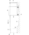
図27は本発明のさらに別な実施形態による車軸検出装置82の構成を示す概略図である。これは車軸検出装置本体62に車両検出装置の機能を併せ持たせたものである。すなわち、この車軸検出装置82は、車軸検出装置本体62と受光器83とから構成されている。受光器83は、車軸検出装置本体62と反対側の路側23において、車両24を検知できる高さ(すなわち、通過車両の車体底面よりも高く、車高よりも低い位置)で支柱84上に設置されている。車軸検出装置本体62の投光部81は、受光器83とほぼ同じ高さに設けられており、投光部81は、最も近くを通過する車両24のタイヤ位置から受光器83へ向けてほぼ水平にパルス光を出射する高さまで、大きな走査角度でパルス光を走査する。
【0081】
しかして、パルス光が路面22に向けて照射されている走査範囲では、車軸検出装置本体62はタイヤ48を検出しており、パルス光を受光器83に向けてほぼ水平に出射している場合には、通過車両24を検出している。すなわち、車両24が通過していない場合には、受光器83は車軸検出装置本体62からほぼ水平にパルス光が出射されたときに、しきい値以上の受光量となり、車両無し信号(off)を出力する。あるいは、車両通過中であれば、受光器83はしきい値以上の受光量となることがないので、車両有り信号(on)を出力する。また、車軸検出装置本体62内の受光部はタイヤ48を検出した時に車軸有り信号(on)を出力する。受光器83の出力と車軸検出装置本体62の出力とは論理積をとって最終的にタイヤを検出したか否かを判断することにより、排気ガスによる誤検知が防止される。すなわち、検知領域内で排気ガスが排出された場合、車軸検出装置本体62は、検知領域内の排気ガスを車軸と誤検知し、車軸有りの信号(on)を出力する。しかし、排気ガスは、車両後方にて排出されるので、このとき受光器83の出力は車両無し(off)となり、その論理積は最終的に車軸を検出していない(off)という出力になり、誤検知が回避される。
【0082】
このような車軸検出装置によれば、車軸検出装置本体62の投光部81が車両検出装置の投光器を兼ねるので、構成が簡単になり、コストも安価にすることができる。なお、この実施形態でも車両検知方式は、回帰反射型としてもよい。
【0083】
(第13の実施形態)
図28は本発明のさらに別な実施形態による車軸検出装置85の構成を示す概略図である。この実施形態も、第12の実施形態と同様、車軸検出装置本体62の投光部81が車両検出装置本体の投光器を兼ねるようにしたものである。この実施形態では、車軸検出装置本体62で走査されるパルス光のうち、路面22に向けて走査されたパルス光をタイヤ検出用に使用し、車軸検出装置本体62から下方へ出射されたパルス光を車両検出用に使用している。つまり、車軸検出装置本体62から下方へ出射されたパルス光を路側23の上面よりも低い位置に設置された反射鏡86で反射させることにより、路面22と平行に出射させ、他方の路側23内に設置された受光器87で受光させるようにしてあり、車両が通過していると、このパルス光が車両24のタイヤ48で遮断され、受光器87で受光されなくなるので、車両有り信号(on)を出力するようにしたものである。
【0084】
この車軸検出装置85でも、受光器87の出力と車軸検出装置本体62の出力との論理積をとることにより、最終的にタイヤ48を検出したか否かを判断され、排気ガスによる誤検知が防止される。また、車両検出用の投光器を別途必要としないので、構成を簡単にすることができる。
【図面の簡単な説明】
【図1】従来の踏み板方式の車軸検出装置を示す概略図である。
【図2】従来の光走査方式の車軸検出装置を示す概略図である。
【図3】同上の車軸検出装置においてタイヤにレーザー光を走査してタイヤを検知する様子を説明する図である。
【図4】タイヤに沿って走査されるレーザー光の照射点を示す図である。
【図5】本発明の一実施形態による車軸検出装置の概略斜視図である。
【図6】同上の車軸検出装置の構成を示すブロック図である。
【図7】同上の車軸検出装置が車両のタイヤに向けてパルス光を出射している様子を示す図である。
【図8】(a)(b)(c)は、タイヤと路面と車体とを判別する原理を説明する図である。
【図9】同上の車軸検出装置の設置位置を決めるために用いる物理量の定義を示す図である。
【図10】タイヤ上におけるパルス光の照射点を示す図である。
【図11】高速で通過する車両と走査線との関係を説明するための図である。
【図12】(a)(b)は、タイヤを判別することが困難なデータを示す図である。
【図13】本発明のさらに別な実施形態による車軸検出装置の光学系を示す概略図である。
【図14】従来例の問題点を説明する図である。
【図15】本発明のさらに別な実施形態による車軸検出装置の光学系を示す概略図である。
【図16】同上の車軸検出装置を用いて車両のタイヤを検出する様子を示す斜視図である。
【図17】複数系統の走査線を得る別な方法を示す概略図である。
【図18】排気ガスでパルス光が反射されてタイヤと誤検知する様子を説明する図である。
【図19】本発明のさらに別な実施形態による車軸検知装置の構成を示す概略図である。
【図20】同上の実施形態における車軸有無判断のためのアルゴリズムを示す図である。
【図21】本発明のさらに別な実施形態による車軸検知装置の構成を示す概略図である。
【図22】本発明のさらに別な実施形態による車軸検知装置の構成を示す斜視図である。
【図23】本発明のさらに別な実施形態による車軸検知装置の構成を示すブロック図である。
【図24】本発明のさらに別な実施形態による車軸検知装置の構成を示す斜視図である。
【図25】本発明のさらに別な実施形態による車軸検知装置の構成を示す概略図である。
【図26】本発明のさらに別な実施形態による車軸検知装置の構成を示す概略図である。
【図27】本発明のさらに別な実施形態による車軸検知装置の構成を示す概略図である。
【図28】本発明のさらに別な実施形態による車軸検知装置の構成を示す概略図である。
【符号の説明】
22 路面 23 路側
24 車両 25 発光素子
26 投光レンズ 28 ポリゴンミラー
30 コントローラ 36 受光素子
37 受光レンズ 48 タイヤ
52 排気ガス 62 車軸検出装置本体
63 車両検出装置の投光器 64 車両検出装置の受光器
67 車両検出装置本体 68 回帰反射板[0001]
BACKGROUND OF THE INVENTION
The present invention relates to an axle detection device for passing vehicles in toll collection devices such as toll roads and toll parking lots.
[0002]
[Prior art]
In toll roads, toll parking lots, etc., it is necessary to count the number of axles (or the number of tires) of passing vehicles in order to determine the type of passing vehicle. As an axle detection device that detects the axle of a vehicle and counts the number of axles, there are, for example, a stepping plate type and an optical scanning type.
[0003]
In the tread plate type axle detection device, as shown in FIG. 1, the
[0004]
However, in such a tread plate type axle detection device, since the pressing force when the
[0005]
In contrast, the optical scanning type
[0006]
[Problems to be solved by the invention]
In the above-described optical scanning type
[0007]
However, when the traveling speed of the
[0008]
Therefore, in order to detect the
[0009]
If it is attempted to increase the number of scans per unit time and not to decrease the number of times of laser light emission per scan, it is necessary to shorten the pulse emission period of the laser diode, but shorten the emission period of the laser diode. As a result, the life of the laser diode is shortened, and there are restrictions on shortening the light emission period of the laser diode from the viewpoint of ensuring safety.
[0010]
Further, in the optical scanning type axle detection device, since the laser light is reflected by the exhaust gas, when the laser light reflected by the exhaust gas is received by the light receiving element, the exhaust gas is erroneously detected as a vehicle tire, There was a problem of misreading the number of axles of the vehicle.
[0011]
The present invention has been made to solve the above-described technical problems, and an object of the present invention is to improve axle detection accuracy in an optical scanning type axle detection apparatus. In particular, it is to improve the axle detection accuracy of a vehicle by improving the axle detection accuracy of a vehicle passing at high speed or by preventing erroneous detection due to exhaust gas.
[0012]
[Means for solving the problems and their functions]
The axle detection device according to
D <(A × Δh) / (V × θ t × Δt)
MeetIt is characterized by doing so.
[0013]
This axle detection device detects the tire in the entire detection area because the farthest distance from the device and the number of pulsed lights irradiated to the tire in a bad tire detection condition is sufficient for tire detection. It is possible to improve the detection accuracy of the tire or the axle.
[0015]
Also,Under the conditions satisfying the above equation, at least one scan line can be run even on the tire of the vehicle passing at a speed V on the side far from the device, so that the tire or axle can be reliably detected, Axle detection accuracy can be improved.
[0016]
Claim2The axle detection device described in (1) scans the pulsed light toward the detection area, obtains the distance to each irradiation point based on the reflected light, and calculates the distance information to the irradiation point and the scanning direction of each pulsed light. Tire detection means for detecting the presence or absence of tires in the detection area; and vehicle detection means for detecting the presence or absence of vehicles in or near the detection area, which are installed on or in the same plane as the scanning surface of the pulsed light. HaveIn the axle detection device, the tire detection unit has a function of detecting the presence or absence of an object having a certain height or more on the road surface, and the detection result by the object detection function in the tire detection unit and the detection result of the vehicle detection unit Based on the above, the abnormality of the vehicle detection means was detected.It is characterized by that.
[0017]
This axle detection device enables the vehicle detection means to detect the presence or absence of a vehicle at the same detection position as the tire detection means, so it can distinguish between exhaust gas and tire, and misdetects the axle by exhaust gas No fear of doing.
[0021]
AlsoSince the abnormality of the vehicle detection means can be detected by the tire detection means, the reliability of the axle detection device can be improved at a low cost.
[0024]
DETAILED DESCRIPTION OF THE INVENTION
(First embodiment)
FIG. 5 is a schematic perspective view showing the
[0025]
The light projecting section of the
[0026]
The scanning direction of the pulsed light emitted from the
[0027]
The light receiving unit includes a
[0028]
The distance calculation unit includes a
[0029]
As described above, when the light emitting
[0030]
On the other hand, when the
[0031]
The time difference /
[0032]
The tire detection unit includes a
[0033]
Specifically, the detection principle of the
[0034]
Furthermore, the
[0035]
Considering the situation where the
Δh = D · Δθ (1)
It can be expressed as.
[0036]
In order to increase the detection accuracy of the
Δh <H… ▲ 2 ▼
And it is sufficient. In particular, if the reflection position (irradiation point of pulsed light) on the
Δh <(H / M)
Or
D <{H / (MΔθ)} (3)
And it is sufficient.
[0037]
Further, the detection of the
[0038]
As shown in FIG. 11, when the length of the tire contact portion is A, the time that the tire contact portion passes through the scanning position of the pulsed light is A / V [sec], and therefore the
NVT <A… ▲ 4 ▼
[0039]
Further, if one pulse cycle time (pulse light emission time interval) of the pulsed light is Δt, and the angle change in the light projection direction (scanning range of the pulsed light) in one scan of the pulsed light is θt, one scan of the pulsed light is required. There is a relationship of T = (θt / Δθ) Δt between the time T and the emission interval angle Δθ of the pulsed light. Here, using the above equation (1), this relationship can be written as the following equation (5).
T = (D · θt · Δt) / Δh (5)
Substituting this formula (5) into the formula (4) and rearranging it gives the following formula (6).
D <(A · Δh) / (N · V · θt · Δt) (6)
In particular, in order to detect the
D <(A · Δh) / (V · θt · Δt) (7)
[0040]
Accordingly, the pulse light is scanned from the tire position of the
[0041]
In addition, if the distance D is shortened in this configuration, the light projecting portion of the
[0042]
(Second Embodiment)
According to the
[0043]
In order to cope with such a problem, not only a signal indicating the presence / absence of the tire 48 (or the axle) but also a signal indicating that the determination of the presence / absence of the
[0044]
Also, if there is an application in which overcounting of the number of axles is a problem, it is determined that there is no tire when the identification is unknown, and if it is an application where axle miscounting is a problem, the tire is used when the identification is unknown. You may make it judge that there exists.
[0045]
(Third embodiment)
FIG. 13 is a schematic view showing an optical system of an axle detection device according to still another embodiment of the present invention. In this axle detection device, a light receiving part composed of a
[0046]
The light receiving field is determined by the focal length of the light receiving lens and the size of the light receiving element, and the light receiving field can be enlarged by shortening the focal length of the light receiving lens even in the conventional optical scanning type axle detection device having the structure. However, in order to increase the amount of reflected light received, it is necessary to increase the lens diameter, and it is difficult to shorten the focal length of the light receiving lens. For this reason, in the conventional axle detection device, as shown in FIG. 14, a plurality of light receiving portions including the
[0047]
On the other hand, according to the axle detection device having the configuration as in this embodiment, the detection area can be expanded without providing a plurality of light receiving portions, and the axle detection device can be reduced in size and cost.
[0048]
(Fourth embodiment)
FIG. 15 is a schematic view showing an optical system of an axle detection device according to still another embodiment of the present invention. In this embodiment, a plurality of reflecting mirror surfaces 28 a and 28 b having different inclinations with respect to the rotation axis are provided on the outer peripheral surface of the
[0049]
Therefore, the
[0050]
Thus, if reverse can be determined, when the
[0051]
In addition, as a method of scanning pulsed light along a plurality of scanning lines, a plurality of light projecting units including a
[0052]
(Fifth embodiment)
In the optical scanning type axle detection device, as shown in FIG. 18, the scanned pulsed light is reflected by the
[0053]
FIG. 19 is a schematic diagram showing the configuration of an
[0054]
In the vehicle detection device, when the
[0055]
That is, in this embodiment, as shown in FIG. 20, when the axle detection device
[0056]
According to such a determination method, when the axle detection device
[0057]
On the other hand, as shown in FIG. 18, when the axle detection device
[0058]
Of course, when the
[0059]
Therefore, according to such an embodiment, the detection accuracy of the
[0060]
In addition, as a vehicle detection apparatus, the sensor using an ultrasonic wave and a millimeter wave other than the optical sensor like a photoelectric sensor is also considered. However, since sensors using ultrasonic waves and millimeter waves have wide directivity, the vehicle is detected immediately after the vehicle has passed through the front surface of the vehicle detection device. For this reason, when the exhaust gas exhausted behind the vehicle exists in the detection region of the axle detection device main body, the axle detection device erroneously detects the exhaust gas, and the ultrasonic and millimeter waves that are the vehicle detection device are detected. The sensor used also detects the vehicle after passing. Therefore, in order to eliminate erroneous detection of exhaust gas, it is necessary to use an optical sensor such as a photoelectric sensor.
[0061]
(Sixth embodiment)
FIG. 21 is a schematic diagram showing a configuration of an axle detection device according to another embodiment that can prevent erroneous detection due to exhaust gas. In this embodiment, a vehicle detection device such as a retroreflective optical sensor is provided instead of the transmission type vehicle detection device. The vehicle detection device includes a vehicle detection device
[0062]
If a transmissive type is used as the vehicle detection device as in the fifth embodiment, wiring work is required on both the projector-side roadside and the receiver-side roadside. If a reflection type vehicle detection device is used, it is only necessary to install a
[0063]
(Seventh embodiment)
FIG. 22 is a schematic diagram showing the configuration of an
[0064]
Now, assuming that three vehicle detection device
[0065]
In this embodiment, the
[0066]
(Eighth embodiment)
FIG. 23 is a block diagram showing a configuration of an
[0067]
The
[0068]
With this configuration, the axle detection device
[0069]
(Ninth embodiment)
An
[0070]
The
[0071]
According to such an embodiment, since the
[0072]
(Tenth embodiment)
For example, as in the embodiment of FIG. 19, when the vehicle detection device is set per height of a normal passenger car body, the light beam does not hit the vehicle body depending on the vehicle type (for example, a sports car type vehicle) The vehicle may not be detected.
[0073]
FIG. 25 is a schematic diagram showing a configuration of an
[0074]
In this
[0075]
Moreover, in this vehicle detection device, when the
[0076]
In this embodiment, the same effect can be obtained by using a transmission type vehicle detection device such as a transmission type photoelectric sensor.
[0077]
(Eleventh embodiment)
In the axle detection device as in the tenth embodiment, when garbage such as dead leaves accumulates on the road surface in front of the vehicle detection device, the vehicle detection device continues to output a vehicle presence signal. Even in this case, if the final determination is made after taking the logical product of the output of the vehicle detection device main body and the output of the axle detection device main body, there is no possibility of erroneously detecting the axle for anything other than the exhaust gas. However, in the tenth embodiment, when dead leaves or the like are accumulated in front of the vehicle detection device, there is a possibility that the exhaust gas is erroneously detected as a tire.
[0078]
The
[0079]
Thus, according to this axle detection device, when the
[0080]
(Twelfth embodiment)
FIG. 27 is a schematic diagram showing a configuration of an
[0081]
Thus, in the scanning range in which the pulsed light is emitted toward the
[0082]
According to such an axle detection device, the
[0083]
(13th Embodiment)
FIG. 28 is a schematic diagram showing the configuration of an
[0084]
Also in this
[Brief description of the drawings]
FIG. 1 is a schematic view showing a conventional tread plate type axle detection device.
FIG. 2 is a schematic view showing a conventional optical scanning type axle detection device;
FIG. 3 is a diagram for explaining a state in which the tire is detected by scanning the tire with laser light in the axle detection device same as above.
FIG. 4 is a diagram showing irradiation points of laser light scanned along a tire.
FIG. 5 is a schematic perspective view of an axle detection device according to an embodiment of the present invention.
FIG. 6 is a block diagram showing the configuration of the axle detection device of the above.
FIG. 7 is a diagram showing a state in which the axle detection device according to the embodiment emits pulsed light toward a vehicle tire.
FIGS. 8A, 8B, and 8C are diagrams for explaining the principle of discriminating a tire, a road surface, and a vehicle body.
FIG. 9 is a diagram showing the definition of physical quantities used to determine the installation position of the axle detection device of the above.
FIG. 10 is a diagram showing an irradiation point of pulsed light on a tire.
FIG. 11 is a diagram for explaining the relationship between a vehicle passing at high speed and a scanning line;
FIGS. 12A and 12B are diagrams showing data that makes it difficult to discriminate tires.
FIG. 13 is a schematic view showing an optical system of an axle detection device according to still another embodiment of the present invention.
FIG. 14 is a diagram illustrating a problem of a conventional example.
FIG. 15 is a schematic view showing an optical system of an axle detection device according to still another embodiment of the present invention.
FIG. 16 is a perspective view showing how a vehicle tire is detected using the axle detection device same as above.
FIG. 17 is a schematic diagram showing another method for obtaining a plurality of scanning lines.
FIG. 18 is a diagram illustrating a state in which pulsed light is reflected by exhaust gas and erroneously detected as a tire.
FIG. 19 is a schematic view showing a configuration of an axle detection device according to still another embodiment of the present invention.
FIG. 20 is a diagram showing an algorithm for determining whether or not there is an axle in the embodiment.
FIG. 21 is a schematic view showing a configuration of an axle detection device according to still another embodiment of the present invention.
FIG. 22 is a perspective view showing a configuration of an axle detection device according to still another embodiment of the present invention.
FIG. 23 is a block diagram showing a configuration of an axle detection device according to still another embodiment of the present invention.
FIG. 24 is a perspective view showing a configuration of an axle detection device according to still another embodiment of the present invention.
FIG. 25 is a schematic view showing a configuration of an axle detection device according to still another embodiment of the present invention.
FIG. 26 is a schematic view showing a configuration of an axle detection device according to still another embodiment of the present invention.
FIG. 27 is a schematic diagram showing the configuration of an axle detection device according to still another embodiment of the present invention.
FIG. 28 is a schematic diagram showing the configuration of an axle detection device according to still another embodiment of the present invention.
[Explanation of symbols]
24
26
30
37
52
63 Projector of
67 Vehicle
Claims (2)
前記パルス光の走査方向を検知する走査方向検知手段と、
前記光走査手段によって走査され、照射点で反射された光を受光する受光手段と、
前記受光手段における受光信号に基づいて、各パルス光の照射点までの距離を演算する距離演算手段と、
前記走査方向検知手段によって得られた走査方向に関する情報と、前記距離演算手段によって得られた照射点までの距離情報に基づいてタイヤの有無を検知するタイヤ検知手段とからなる車軸検出装置において、
検知領域内で光走査手段から最も遠い領域を走行すると想定された車両のタイヤ上において、前記パルス光の1パルス周期毎に照射点の移動する距離が、タイヤ断面の高さよりも十分小さくなるようにし、
且つ前記検知領域内で前記光走査手段から最も遠い領域を走行すると想定された車両のタイヤまでの距離をD、光走査によってタイヤとして識別可能なタイヤ部分の最小長さをA、前記車両のタイヤ上において前記パルス光の1パルス周期毎に照射点の移動する距離をΔh、前記光走査手段によるパルス光の走査角度をθ t 、検知領域を通過する車両の最大速度想定値をV、前記パルス光の1パルス周期時間をΔtとするとき、
前記距離Dが
D<(A×△h)/(V×θ t ×Δt)
を満たすようにしたことを特徴とする車軸検出装置。Optical scanning means for scanning the pulsed light toward the detection region;
A scanning direction detecting means for detecting a scanning direction of the pulsed light;
A light receiving means for receiving the light scanned by the light scanning means and reflected at the irradiation point;
Based on the light reception signal in the light receiving means, distance calculating means for calculating the distance to the irradiation point of each pulsed light,
In an axle detection device comprising information related to the scanning direction obtained by the scanning direction detection means and tire detection means for detecting the presence or absence of a tire based on distance information to the irradiation point obtained by the distance calculation means,
On the tire of the vehicle assumed to travel the farthest area from the optical scanning means in the detection area, the distance that the irradiation point moves for each pulse period of the pulsed light is sufficiently smaller than the height of the tire cross section. West,
In addition, the distance to the tire of the vehicle assumed to travel in the region farthest from the optical scanning means within the detection region is D, the minimum length of the tire portion that can be identified as a tire by optical scanning is A, and the tire of the vehicle In the above, the distance that the irradiation point moves for each pulse period of the pulsed light is Δh, the scanning angle of the pulsed light by the optical scanning means is θ t , the maximum estimated speed of the vehicle passing through the detection region is V, and the pulse When one pulse period time of light is Δt,
The distance D is
D <(A × Δh) / (V × θ t × Δt)
An axle detection device characterized by satisfying the above.
前記パルス光の走査面と同一平面上もしくはその近傍に設置され、検知領域もしくはその近傍における車両の有無を検出する車両検知手段と、
を有する車軸検出装置において、
前記タイヤ検出手段は、路面上の一定高さ以上の物体の有無を検知する機能を備え、タイヤ検出手段における当該物体有無検知機能による検知結果と前記車両検知手段の検知結果とに基づき、車両検知手段の異常を検出するようにしたことを特徴とする車軸検出装置。Pulse light is scanned toward the detection area, the distance to each irradiation point is obtained based on the reflected light, and the presence or absence of a tire in the detection area is detected from the distance information to the irradiation point and the scanning direction of each pulse light. Tire detecting means for
Is placed on or near the scanning surface flush with said pulsed light, the detection area also is properly and vehicle detection means for detecting the presence of the vehicle in the vicinity thereof,
In an axle detection device having
The tire detection means has a function of detecting the presence or absence of an object of a certain height or higher on the road surface, and vehicle detection based on a detection result by the object detection function in the tire detection means and a detection result of the vehicle detection means. An axle detection device characterized by detecting an abnormality of the means .
Priority Applications (1)
| Application Number | Priority Date | Filing Date | Title |
|---|---|---|---|
| JP18806299A JP3714040B2 (en) | 1999-05-27 | 1999-05-27 | Axle detection device |
Applications Claiming Priority (1)
| Application Number | Priority Date | Filing Date | Title |
|---|---|---|---|
| JP18806299A JP3714040B2 (en) | 1999-05-27 | 1999-05-27 | Axle detection device |
Publications (2)
| Publication Number | Publication Date |
|---|---|
| JP2000339586A JP2000339586A (en) | 2000-12-08 |
| JP3714040B2 true JP3714040B2 (en) | 2005-11-09 |
Family
ID=16217041
Family Applications (1)
| Application Number | Title | Priority Date | Filing Date |
|---|---|---|---|
| JP18806299A Expired - Lifetime JP3714040B2 (en) | 1999-05-27 | 1999-05-27 | Axle detection device |
Country Status (1)
| Country | Link |
|---|---|
| JP (1) | JP3714040B2 (en) |
Families Citing this family (11)
| Publication number | Priority date | Publication date | Assignee | Title |
|---|---|---|---|---|
| JP3755402B2 (en) * | 2000-12-14 | 2006-03-15 | オムロン株式会社 | Axle detection device |
| JP4036119B2 (en) * | 2003-03-12 | 2008-01-23 | オムロン株式会社 | Vehicle detection device and vehicle detection method |
| PL2306428T3 (en) | 2009-10-01 | 2012-04-30 | Kapsch Trafficcom Ag | Device and method for determining the direction, speed and/or distance of vehicles |
| PT2306425E (en) | 2009-10-01 | 2011-11-10 | Kapsch Trafficcom Ag | Device and method for detecting wheel axles |
| JP5558077B2 (en) * | 2009-10-30 | 2014-07-23 | 三菱電機株式会社 | Vehicle detection device and toll charge system |
| JP5701162B2 (en) * | 2011-06-20 | 2015-04-15 | 住友重機械工業株式会社 | Mechanical parking lot |
| JP5911681B2 (en) * | 2011-08-22 | 2016-04-27 | 株式会社東芝 | Moving rotator detection device |
| JP5936649B2 (en) * | 2014-06-04 | 2016-06-22 | 三菱電機株式会社 | Vehicle detection device and toll charge system |
| JP2017040546A (en) * | 2015-08-19 | 2017-02-23 | 株式会社デンソー | Object detection device |
| JP7696259B2 (en) * | 2021-09-03 | 2025-06-20 | 三菱重工機械システム株式会社 | Axle Detection System |
| JP7641866B2 (en) * | 2021-09-10 | 2025-03-07 | 三菱重工機械システム株式会社 | Vehicle detector, vehicle detection method, and program |
-
1999
- 1999-05-27 JP JP18806299A patent/JP3714040B2/en not_active Expired - Lifetime
Also Published As
| Publication number | Publication date |
|---|---|
| JP2000339586A (en) | 2000-12-08 |
Similar Documents
| Publication | Publication Date | Title |
|---|---|---|
| KR100459478B1 (en) | Vehicle detection apparatus and method using laser sensor | |
| JP3714040B2 (en) | Axle detection device | |
| KR101328016B1 (en) | Collision avoidance apparatus for car based on laser sensor and ultrasonic sensor and collision avoidance apparatus thereof | |
| JP3240839B2 (en) | Vehicle width measuring device | |
| KR20190061094A (en) | Improved laser rangefinder sensor | |
| AU2008229875A1 (en) | Method for detecting and documenting traffic violations at a traffic light | |
| JP2009516838A (en) | Detecting device for tire depth and shape, vehicle speed and ground clearance during running | |
| JP3196732B2 (en) | Inter-vehicle distance detection device | |
| JP4036119B2 (en) | Vehicle detection device and vehicle detection method | |
| JP4791147B2 (en) | Object detection unit, object detection apparatus, moving object detection apparatus for crossing road, and program | |
| JP4301703B2 (en) | Laser reflective vehicle detector | |
| KR20200111008A (en) | Vehicle detection system using distance sensor and method of the same | |
| JP3498527B2 (en) | Vehicle type identification device and speed measurement device | |
| US7932835B2 (en) | Vehicle zone detection system and method | |
| JPH09178857A (en) | Device for measuring the distance between vehicles | |
| JP3606032B2 (en) | Axle detection device and passage fee calculation device | |
| JP3653862B2 (en) | Vehicle curve diameter estimation device and target preceding vehicle detection device | |
| EP1256015B1 (en) | Motor vehicle trajectory measurement | |
| JP3804418B2 (en) | Axle detection device | |
| JP5404466B2 (en) | Parking lot entrance warning device | |
| JP3351184B2 (en) | Axis number detection device and vehicle width detection device | |
| KR102287958B1 (en) | System and method for remote sensing visible ligth transmittance of car window | |
| US7432490B2 (en) | Method and apparatus for detecting an object in a motor vehicle environment | |
| JP7614485B2 (en) | Laser distance measurement device, object detection system | |
| KR101900371B1 (en) | System and Method for Car Detecting by Using Pulsed Laser Sensor |
Legal Events
| Date | Code | Title | Description |
|---|---|---|---|
| A977 | Report on retrieval |
Free format text: JAPANESE INTERMEDIATE CODE: A971007 Effective date: 20041222 |
|
| A131 | Notification of reasons for refusal |
Free format text: JAPANESE INTERMEDIATE CODE: A131 Effective date: 20050125 |
|
| A521 | Written amendment |
Free format text: JAPANESE INTERMEDIATE CODE: A523 Effective date: 20050323 |
|
| TRDD | Decision of grant or rejection written | ||
| A01 | Written decision to grant a patent or to grant a registration (utility model) |
Free format text: JAPANESE INTERMEDIATE CODE: A01 Effective date: 20050802 |
|
| A61 | First payment of annual fees (during grant procedure) |
Free format text: JAPANESE INTERMEDIATE CODE: A61 Effective date: 20050815 |
|
| R150 | Certificate of patent or registration of utility model |
Free format text: JAPANESE INTERMEDIATE CODE: R150 |
|
| FPAY | Renewal fee payment (event date is renewal date of database) |
Free format text: PAYMENT UNTIL: 20080902 Year of fee payment: 3 |
|
| FPAY | Renewal fee payment (event date is renewal date of database) |
Free format text: PAYMENT UNTIL: 20090902 Year of fee payment: 4 |
|
| FPAY | Renewal fee payment (event date is renewal date of database) |
Free format text: PAYMENT UNTIL: 20090902 Year of fee payment: 4 |
|
| FPAY | Renewal fee payment (event date is renewal date of database) |
Free format text: PAYMENT UNTIL: 20100902 Year of fee payment: 5 |
|
| FPAY | Renewal fee payment (event date is renewal date of database) |
Free format text: PAYMENT UNTIL: 20100902 Year of fee payment: 5 |
|
| FPAY | Renewal fee payment (event date is renewal date of database) |
Free format text: PAYMENT UNTIL: 20110902 Year of fee payment: 6 |
|
| FPAY | Renewal fee payment (event date is renewal date of database) |
Free format text: PAYMENT UNTIL: 20110902 Year of fee payment: 6 |
|
| FPAY | Renewal fee payment (event date is renewal date of database) |
Free format text: PAYMENT UNTIL: 20120902 Year of fee payment: 7 |
|
| FPAY | Renewal fee payment (event date is renewal date of database) |
Free format text: PAYMENT UNTIL: 20130902 Year of fee payment: 8 |
|
| EXPY | Cancellation because of completion of term |