JP7542735B2 - Method and apparatus for determining false positives of a lidar sensor - Google Patents
Method and apparatus for determining false positives of a lidar sensor Download PDFInfo
- Publication number
- JP7542735B2 JP7542735B2 JP2023518140A JP2023518140A JP7542735B2 JP 7542735 B2 JP7542735 B2 JP 7542735B2 JP 2023518140 A JP2023518140 A JP 2023518140A JP 2023518140 A JP2023518140 A JP 2023518140A JP 7542735 B2 JP7542735 B2 JP 7542735B2
- Authority
- JP
- Japan
- Prior art keywords
- lidar sensor
- reflection
- retroreflected
- clusters
- false positives
- Prior art date
- Legal status (The legal status is an assumption and is not a legal conclusion. Google has not performed a legal analysis and makes no representation as to the accuracy of the status listed.)
- Active
Links
Images


Classifications
-
- G—PHYSICS
- G01—MEASURING; TESTING
- G01S—RADIO DIRECTION-FINDING; RADIO NAVIGATION; DETERMINING DISTANCE OR VELOCITY BY USE OF RADIO WAVES; LOCATING OR PRESENCE-DETECTING BY USE OF THE REFLECTION OR RERADIATION OF RADIO WAVES; ANALOGOUS ARRANGEMENTS USING OTHER WAVES
- G01S7/00—Details of systems according to groups G01S13/00, G01S15/00, G01S17/00
- G01S7/48—Details of systems according to groups G01S13/00, G01S15/00, G01S17/00 of systems according to group G01S17/00
- G01S7/4802—Details of systems according to groups G01S13/00, G01S15/00, G01S17/00 of systems according to group G01S17/00 using analysis of echo signal for target characterisation; Target signature; Target cross-section
-
- G—PHYSICS
- G01—MEASURING; TESTING
- G01S—RADIO DIRECTION-FINDING; RADIO NAVIGATION; DETERMINING DISTANCE OR VELOCITY BY USE OF RADIO WAVES; LOCATING OR PRESENCE-DETECTING BY USE OF THE REFLECTION OR RERADIATION OF RADIO WAVES; ANALOGOUS ARRANGEMENTS USING OTHER WAVES
- G01S17/00—Systems using the reflection or reradiation of electromagnetic waves other than radio waves, e.g. lidar systems
- G01S17/02—Systems using the reflection of electromagnetic waves other than radio waves
- G01S17/06—Systems determining position data of a target
- G01S17/42—Simultaneous measurement of distance and other co-ordinates
-
- G—PHYSICS
- G01—MEASURING; TESTING
- G01S—RADIO DIRECTION-FINDING; RADIO NAVIGATION; DETERMINING DISTANCE OR VELOCITY BY USE OF RADIO WAVES; LOCATING OR PRESENCE-DETECTING BY USE OF THE REFLECTION OR RERADIATION OF RADIO WAVES; ANALOGOUS ARRANGEMENTS USING OTHER WAVES
- G01S17/00—Systems using the reflection or reradiation of electromagnetic waves other than radio waves, e.g. lidar systems
- G01S17/88—Lidar systems specially adapted for specific applications
- G01S17/93—Lidar systems specially adapted for specific applications for anti-collision purposes
- G01S17/931—Lidar systems specially adapted for specific applications for anti-collision purposes of land vehicles
-
- G—PHYSICS
- G01—MEASURING; TESTING
- G01S—RADIO DIRECTION-FINDING; RADIO NAVIGATION; DETERMINING DISTANCE OR VELOCITY BY USE OF RADIO WAVES; LOCATING OR PRESENCE-DETECTING BY USE OF THE REFLECTION OR RERADIATION OF RADIO WAVES; ANALOGOUS ARRANGEMENTS USING OTHER WAVES
- G01S7/00—Details of systems according to groups G01S13/00, G01S15/00, G01S17/00
- G01S7/48—Details of systems according to groups G01S13/00, G01S15/00, G01S17/00 of systems according to group G01S17/00
- G01S7/483—Details of pulse systems
- G01S7/486—Receivers
- G01S7/487—Extracting wanted echo signals, e.g. pulse detection
- G01S7/4876—Extracting wanted echo signals, e.g. pulse detection by removing unwanted signals
-
- B—PERFORMING OPERATIONS; TRANSPORTING
- B60—VEHICLES IN GENERAL
- B60W—CONJOINT CONTROL OF VEHICLE SUB-UNITS OF DIFFERENT TYPE OR DIFFERENT FUNCTION; CONTROL SYSTEMS SPECIALLY ADAPTED FOR HYBRID VEHICLES; ROAD VEHICLE DRIVE CONTROL SYSTEMS FOR PURPOSES NOT RELATED TO THE CONTROL OF A PARTICULAR SUB-UNIT
- B60W2420/00—Indexing codes relating to the type of sensors based on the principle of their operation
- B60W2420/40—Photo, light or radio wave sensitive means, e.g. infrared sensors
- B60W2420/408—Radar; Laser, e.g. lidar
Landscapes
- Engineering & Computer Science (AREA)
- Physics & Mathematics (AREA)
- Computer Networks & Wireless Communication (AREA)
- General Physics & Mathematics (AREA)
- Radar, Positioning & Navigation (AREA)
- Remote Sensing (AREA)
- Electromagnetism (AREA)
- Optical Radar Systems And Details Thereof (AREA)
Description
本発明は、車両周辺のスキャンプロセス時にライダーセンサの誤検知を判定するための方法に関する。 The present invention relates to a method for determining false positives of a lidar sensor during a scanning process around a vehicle.
本発明は、更に、車両周辺のスキャンプロセス時にライダーセンサの誤検知を判定するための装置に関する。 The present invention further relates to an apparatus for determining false positives of a lidar sensor during a scanning process of the vehicle's surroundings.
独国特許公開第199 47 593(A1)号によれば、車両に搭載される車両用レーダ装置が公知である。レーダ装置は、車両が走行する路面と平行なレーダビームで走査範囲を走査するためのレーダビーム走査装置を有する。更に、レーダ装置は、反射された波に基づいて被検知対象物画像を作成するために、反射されたレーダビームの波を受信するための対象物検知装置を有し、対象物検知装置は、作成された被検知対象物画像がゴーストエコーであるか否かを判定するためのゴーストエコー判定装置を含む。 From German Patent Publication No. 199 47 593 (A1), a radar device for vehicles mounted on a vehicle is known. The radar device has a radar beam scanning device for scanning a scanning range with a radar beam parallel to the road surface on which the vehicle is traveling. Furthermore, the radar device has an object detection device for receiving reflected radar beam waves in order to create an image of the detected object based on the reflected waves, and the object detection device includes a ghost echo determination device for determining whether the created image of the detected object is a ghost echo or not.
本発明の目的は、ライダーセンサの誤検知を判定するための新規方法及び新規装置を提供することである。 The object of the present invention is to provide a new method and a new device for determining false detection of a lidar sensor.
上記の目的は、本発明により、請求項1に記載の特徴を有する方法及び請求項7に記載の特徴を有する装置によって解決される。
The above object is solved according to the present invention by a method having the features of
本発明の有利な実施形態は、従属請求項の主題である。 Advantageous embodiments of the invention are the subject matter of the dependent claims.
車両周辺のスキャンプロセス時にライダーセンサの誤検知を判定するための方法において、本発明によれば、前記ライダーセンサのスキャン範囲内で前記ライダーセンサに向けて再帰反射される各レーザパルスについて、前記レーザパルスが異なる距離で複数回再帰反射されたか否かをチェックする。更に、複数回再帰反射されたレーザパルスのうちの第1の反射をクラスタ化する。生成されたクラスタからの反射の距離を評価することによって、前記レーザパルスが少なくともほぼ均一な反射面で反射されていることが判明したとき、それぞれの前記第1の反射に続く更なる反射を誤検知として標示する。 In a method for determining false positives of a lidar sensor during a scanning process around a vehicle, according to the present invention, for each laser pulse that is retroreflected towards the lidar sensor within the scanning range of the lidar sensor, it is checked whether the laser pulse is retroreflected multiple times at different distances. Furthermore, a first reflection of the multiple retroreflected laser pulses is clustered. When the distance of the reflections from the generated cluster is evaluated to determine that the laser pulse is reflected from an at least approximately uniform reflective surface, further reflections following each of the first reflections are marked as false positives.
本方法により、車両周辺のスキャンプロセス時に、ライダーのゴーストターゲット又はゴーストエコーとも称される誤検知の判定が、信頼性のある方法で実現可能である。これにより、実際の交通状況で、例えば別の車両のウインドウガラスといった反射材料から生じるライダーの重大な制約を回避することができる。したがって、運転者支援システム、また特に自動化された、とりわけ高度に自動化された又は自律走行する車両の運転者支援システムにおける運転の信頼性を高めることができる。 The method allows reliable determination of false positives, also called ghost targets or ghost echoes, of the lidar during the scanning process around the vehicle. This avoids a significant limitation of the lidar in real traffic situations, which arises from reflective materials, for example the window glass of another vehicle. This thus increases the reliability of operation in driver assistance systems, and in particular in driver assistance systems of automated, in particular highly automated or autonomous vehicles.
本方法の考えられる実施形態では、追加的に、前記クラスタの前記更なる反射が前記第1の反射よりも大きい距離で起きた場合にのみ、前記更なる反射を誤検知として標示する。これによって、誤検知の判定の信頼性が更に高まる。 A possible embodiment of the method additionally includes marking the further reflection of the cluster as a false positive only if the further reflection occurs at a greater distance than the first reflection. This further increases the reliability of the false positive determination.
本方法の更に考えられる実施形態では、前記クラスタの前記表面の決定時、平面状の表面、すなわち平坦な表面を有するクラスタと、湾曲した表面を有するクラスタと、正確に1つの空間方向に延在するクラスタと、3つの空間方向に延在するクラスタと、を区別する。この区別に基づいてクラスタを分類することができ、このクラスタに誤検知が存在し得るか否かを分類に基づいて簡単な方法で決定可能になる。 In a further possible embodiment of the method, when determining the surfaces of the clusters, a distinction is made between clusters with planar, i.e. flat, surfaces, clusters with curved surfaces, clusters that extend in exactly one spatial direction and clusters that extend in three spatial directions. Based on this distinction, the clusters can be classified and based on the classification it is possible to determine in a simple way whether there may be a false positive in this cluster.
本方法の更に考えられる実施形態では、平面状の表面を有するクラスタ及び少し湾曲した表面を有するクラスタのみを、ほぼ均一な反射面と見做す。 In a further possible embodiment of the method, only clusters with planar surfaces and clusters with slightly curved surfaces are considered to be approximately uniformly reflective.
本方法の更に考えられる実施形態では、正確に1つの空間方向に延在するクラスタを、対象物の縁部を表すクラスタと見做す。 In a further possible embodiment of the method, clusters that extend in exactly one spatial direction are considered to represent the edge of an object.
本方法の更に考えられる実施形態では、3つの空間方向に延在するクラスタを、粉塵及び/又は霧及び/又は微粒子構造物を表すクラスタと見做す。 In a further possible embodiment of the method, clusters extending in three spatial directions are considered to be clusters representing dust and/or mist and/or particulate structures.
車両周辺のスキャンプロセス時にライダーセンサの誤検知を判定するための装置は、本発明によれば、
―前記ライダーセンサのスキャン範囲内で前記ライダーセンサに向けて再帰反射される各レーザパルスについて、前記レーザパルスが異なる距離で複数回再帰反射されたか否かをチェックし、
―複数回再帰反射されたレーザパルスのうちの第1の反射をクラスタ化し、
―生成されたクラスタからの反射の距離を評価することによって、前記レーザパルスが少なくともほぼ均一な反射面で反射されたことが判明したとき、それぞれの前記第1の反射に続く更なる反射を誤検知として標示するように形成された評価ユニットを備えている。
According to the present invention, an apparatus for determining a false positive of a lidar sensor during a scanning process of a vehicle surroundings comprises:
- for each laser pulse that is retroreflected towards the LIDAR sensor within a scan range of the LIDAR sensor , checking whether the laser pulse is retroreflected multiple times at different distances;
- clustering the first reflections of multiple retroreflected laser pulses;
- an evaluation unit configured to indicate, by evaluating the distance of the reflections from the generated cluster, further reflections following each said first reflection as false positives when it is found that the laser pulse has been reflected from an at least approximately uniform reflecting surface.
本装置によって、車両周辺のスキャンプロセス時に、ライダーセンサの誤検知の判定が、信頼性のある方法で可能となる。これにより、実際の交通状況で、例えば別の車両のウインドウガラスといった反射材料から生じるライダーの重大な制約を回避することができる。したがって、運転者支援システム、また特に自動化された、とりわけ高度に自動化された又は自律走行する車両の運転者支援システムにおける運転の信頼性を高めることができる。 The device enables a reliable determination of false positives of the lidar sensor during the scanning process around the vehicle. This makes it possible to avoid significant limitations of the lidar in real traffic situations, which arise from reflective materials, e.g. the window glass of another vehicle. This therefore makes it possible to increase the reliability of operation in driver assistance systems, and in particular in driver assistance systems of automated, in particular highly automated or autonomous vehicles.
以下、図面を参照して、本発明の例示的な実施形態をより詳細に説明する。 An exemplary embodiment of the present invention will now be described in more detail with reference to the drawings.
互いに対応する部分は、全ての図面において同一の符号が付けられている。 Corresponding parts are given the same reference numbers in all drawings.
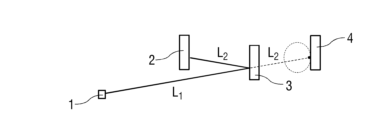
図1には、ライダーセンサ1、対象物2、及び対象物2からの拡散反射時におけるレーザビームL 1
の光路が示されている。
FIG. 1 shows a
ライダーセンサ1により、車両5を取り囲む交通状況を精確に三次元で理解することが可能であるため、ライダーセンサ1は、図4に詳しく示されているように、車両周辺の検出において車両5及びその運転者支援システム、例えば、自動化された、特に高度に自動化された又は自律走行する車両5にとって極めて重要である。ただし、このような安全上重要なシナリオにおける適用のために、図11に示されたライダーセンサの誤検知又は距離の誤測定を判定することが決定的に重要である。このような誤検知の検知に失敗することは、車両5の縦方向及び/又は横方向の誘導において危険な自動介入につながるおそれがあり、その結果、危険な状況、例えば不適切な緊急制動が引き起こされるおそれがある。
The
ライダーセンサ1は、一般に極めて低い誤検知率、すなわち低いノイズレベルを特徴とする。ほとんどの対象材料では、入射レーザビームL1、L2が拡散して、すなわち考えられる全ての方向に反射される。これは、光の一部が直接ライダーセンサ1に再帰反射されることを意味し、これによって精確な距離測定が可能となる。
The
ただし、高反射性の表面では鏡面反射が優勢である。これは、図2に詳しく示されており、図2には、ライダーセンサ1、2つの対象物2、3、及び一方の対象物からの鏡のような反射時及び他方の対象物からの拡散反射時におけるレーザビームL1、L2の光路が示されている。
However, for highly reflective surfaces, specular reflection dominates, and this is shown in more detail in Figure 2, which shows a
ここで、レーザビームL1は、ライダーセンサ1から離れるように偏向され、レーザビームL2として、例えば対象物2といった、鏡に非類似である別の反射性の表面に当たる場合がある。その場合、ライダーセンサ1は、対象物3の表面までのレーザビームL1の距離ではなく、両方のレーザビームL1、L2のジグザグ経路の合計長さを測定する。
Here, laser beam L1 may be deflected away from LIDAR
ライダーセンサ1は、その場合、レーザビームL2が偏向したことを示す情報を有しないので、直線に沿った距離測定が推定される。これにより、レーザビームL1に沿った初期送出方向に沿って誤検知が生じ、その結果、図3に示されたゴースト対象物4の検知をもたらす。
The
これは根本的な問題であって、無視された場合には重大なエラーを引き起こすおそれがある。実際の交通状況では、鏡のような高反射性の表面が、別の車両6(図4に示されている)のウインドウガラス7の形態で出現することがよくある。鏡のような高反射性の表面は、完全に鏡面反射しない場合であっても、入射レーザビームL
1 の少なくとも一部を偏向させる。その後、偏向したレーザビームL
2 が高反射性の二次対象物2、例えば交通標識8に当たると、その結果生じる間接経路は、例えば車両のウインドウガラスでの拡散反射によって形成された直接経路よりも優勢になり得る。
This is a fundamental problem, which, if ignored, can lead to significant errors. In real traffic situations, a highly reflective surface, such as a mirror, often appears in the form of a
このような状況は、図4に例示されている。図4には、ライダーセンサ1を有する車両5と、車両5の前方に存在する更なる車両6として形成された対象物3と、交通標識8として形成された更なる対象物2と、ゴースト対象物4と、からなる交通シナリオが示されている。
Such a situation is illustrated in Fig. 4, which shows a traffic scenario consisting of a vehicle 5 with a
ここで、このようなゴースト対象物4は、車両5の前方の路面FB上に現れる。正確な位置は両方の車両5、6間の相対的距離と一次ターゲット及び二次ターゲット、例えばウインドウガラス7及び交通標識8の間の距離とに依存するので、このような誤検知は、長時間にわたって一定になり得るが、異常なダイナミクスを有することもある。この種の反射作用が認識されない場合、車両5の運転者支援システム又は自動走行用のシステムがゴースト対象物4に反応し、車両5の縦方向及び/又は横方向の制御において誤った介入、例えば、緊急制動又は回避操作を引き起こす危険性がある。
Now, such a
このような反射作用の検知及びそれに続くゴースト対象物の高い信頼性での検知を可能にするため、車両周辺のスキャンプロセス時におけるライダーセンサ1の誤検知の判定が企図されており、以下の図5~図11に基づいてこれを説明する。
To enable reliable detection of such reflections and subsequent ghost objects, a determination of false positives of the
ここで、図5には、対象物2とライダーセンサ1との間に存在する対象物3に、ライダーセンサ1を使用して射出されたレーザビームL1が部分的にのみ当たったときの、ライダーセンサ1及び2つの対象物2、3が示されている。この場合、2つの反射されたレーザパルスR1、R2が発生する。
5 shows a
図6には、ライダーセンサ1、対象物2、及び粉塵及び/又は霧によってライダーセンサ1と対象物2との間に形成された更なる対象物3が示されている。粉塵及び/又は霧により、2つの反射されたレーザパルスR1、R2が同様に発生する。
6 shows a
図7には、ライダーセンサ1、部分透過性対象物3、例えば車両6のウインドウガラス7、2つの非透過性対象物2、9が示されている。
Figure 7 shows a
このような部分透過性対象物3、例えばガラスウインドウは、3つの異なる距離測定を引き起こす場合がある。ここで、反射されたレーザパルスR1によって示されているように、不具合のある、場合によっては汚れたウインドウガラス7の直接的な拡散反射が例えば生じ得る。
Such a partially
また、反射されたレーザパルスR2、R2’によって示されたゴースト反射を引き起こす可能性のある、ガラス表面上の鏡面反射も生じ得る。特に、反射されたレーザパルスR2は、元のビーム方向に沿う誤検知のレーザパルスR2’として伝達される。 There may also be specular reflections on the glass surface that can cause ghost reflections shown by the reflected laser pulses R2 , R2 '. In particular, the reflected laser pulse R2 is transmitted as a false positive laser pulse R2 ' along the original beam direction.
更に、ガラスを通る透過と背景対象物として形成された対象物2での拡散反射とにより、反射されたレーザパルスR3が生じ得る。
Furthermore, a reflected laser pulse R3 may result from transmission through the glass and diffuse reflection at the
詳しくは図示されていない実施形態では、反射されたレーザパルスR2の長さが、反射されたレーザパルスR3の長さを超える場合もある。ただし、反射されたレーザパルスR1によって示された直接的な拡散反射は、常に、最短距離で受光された第1の反射である。 In embodiments not specifically shown, the length of reflected laser pulse R2 may exceed the length of reflected laser pulse R3 , although the direct diffuse reflection exhibited by reflected laser pulse R1 is always the first reflection received at the shortest distance.
詳しくは図示されていない例示的な実施形態では、他のビーム経路も考えられ、例えば背景対象物として形成された対象物2に当たった後のウインドウガラス7の背面からの反射が挙げられるが、これはより高次かつ著しくより弱い。
In an exemplary embodiment not shown in detail, other beam paths are also possible, for example reflection from the rear surface of the
例えば反射されたレーザパルスR2’などの誤検知を認識するためには、最初に、図5及び図6に示されたシナリオを互いに区別する必要がある。このような区別は、図7に示されたシナリオにおいて全てのレーザビームがウインドウガラス7で反射されたレーザパルスR1のように弱い直接反射を引き起こすわけではないという事実から、困難である。
In order to recognize a false positive, such as the reflected laser pulse R2 ', it is first necessary to distinguish the scenarios shown in Figures 5 and 6 from each other. Such a distinction is made difficult by the fact that in the scenario shown in Figure 7, not all laser beams cause a direct reflection as weak as the laser pulse R1 reflected by the
図8は、より複雑な状況に基づいてこの困難性を詳しく示している。この場合、図8には、ライダーセンサ1、部分透過性対象物3、3つの非透過性対象物2、9、10、及び反射されたレーザパルスR1~R4の光路が示されている。
Figure 8 illustrates this difficulty in more detail based on a more complex situation, showing a
透過性対象物3、例えば車両6のウインドウガラス7での直接的な拡散反射は、対象物3の表面上で少数の第1の反射を招き、ここで第1の反射は正方形で図示されている。
Direct diffuse reflection at a
一部のレーザビームでは対象物3での鏡面反射が優勢であり、それ以外のレーザビームでは対象物3での透過性経路が優勢であるので、対象物2及び9での反射が生成される。これにより、第1の反射が対象物2及び9で最初に発生するように、対象物3を通過するレーザビームの経路が生じる場合がある。
For some laser beams, specular reflection at
更に、レーザビームの第2の反射は三角形で、第3の反射は円で図示されている。 Furthermore, the second reflection of the laser beam is illustrated as a triangle and the third reflection as a circle.
測定における誤検知を判定するために、ライダーセンサ1を使用して実行される完全なスキャンプロセスを、第2の反射、場合によってはより高次の反射を伴う測定について走査することが企図されている。
To determine false positives in the measurements, it is contemplated that the complete scanning process performed using the
続いて、隣接する点をまとめるために、ユークリッド距離による単純なクラスタリングアルゴリズムが、図9~図11に正方形で示されている全ての第1の反射に対して適用される。 A simple clustering algorithm based on Euclidean distance is then applied to all first reflections, shown as squares in Figures 9-11, to group adjacent points.
こうして形成された拡張型クラスタC1、C2ごとに主成分分析が実行されることで、分類された3つの固有値λ1≧λ2≧λ3が得られる。クラスタC1、C2は、図9~図11に詳しく示されている。 By performing principal component analysis on each of the expanded clusters C1 and C2 thus formed, three classified eigenvalues λ1 ≧ λ2 ≧ λ3 are obtained. Clusters C1 and C2 are shown in detail in Figures 9 to 11.
λ1、λ2≫λ3となる平面状のクラスタC1、C2、及び少し湾曲した表面を有するクラスタC1、C2は、反射性の表面の候補として標示される。それに対して、一方向にのみ延在する(λ1≫λ2、λ3)クラスタC1、C2は、高確率で対象物縁部から生じるものであるため、標示されない。全ての方向に延在する(λ1≒λ2≒λ3)クラスタC1、C2は、高確率で霧及び/又は粉塵及び/又は超微粒子構造物、例えば、木々又は植物から生じるものであり、同様に標示されない。 Planar clusters C1, C2 with λ1, λ2 >> λ3 and clusters C1, C2 with slightly curved surfaces are marked as candidates for reflective surfaces. In contrast, clusters C1, C2 that extend in only one direction (λ1 >> λ2, λ3) are not marked, since they most likely originate from object edges. Clusters C1, C2 that extend in all directions (λ1 ≈ λ2 ≈ λ3) are also not marked, since they most likely originate from fog and/or dust and/or ultrafine structures, e.g. trees or plants.
以下の2つの条件を満足する測定は、誤検知の反射又は誤検知Eとして標示される。 Any measurement that meets the following two conditions will be marked as a false positive reflection or false positive E.
1.標示されたクラスタC1、C2によって広がる空間(第1の反射の破線の囲みによって図9~図11に示されている)を通過するレーザビームに沿った測定から反射が生じている。 1. The reflections arise from measurements along the laser beam passing through the space spanned by the labeled clusters C1, C2 (shown in Figures 9-11 by the dashed box of the first reflection).
2.反射までの距離は、標示されたクラスタC1までの距離よりも大きい、すなわち、反射はライダーセンサから見てクラスタC1、C2の後方にある。 2. The distance to the reflection is greater than the distance to the labeled cluster C1, i.e., the reflection is behind clusters C1 and C2 as seen by the lidar sensor.
図9は、ライダーセンサ1、2つの対象物2、3、及び反射されたレーザパルスR1、R2の光路を示している。ここで、レーザビームは、対象物2の縁部で一部が反射され、残りの部分が更なる対象物で反射される。その場合、対象物2の縁部での反射が第1の反射となり、更なる対象物3での反射が第2の反射となる。第2の反射に伴って拡張された部位はないので、第1の反射の領域における一つのクラスタC1のみが標示される。更なる反射が続かない残りの反射(×印で図示されている)は、標示されない。
9 shows the lidar sensor 1 , the two
図10には、ライダーセンサ1、2つの対象物2、9、並びに粉塵及び/又は霧によってライダーセンサ1と対象物2、9との間に形成された更なる対象物3が示されている。更なる反射(三角形で図示されている)が続く全ての反射(正方形で図示されている)は、一つのクラスタC1にまとめられる。
In FIG. 10, a
図11には、ライダーセンサ1並びに3つの対象物2、3及び9が示されており、対象物3は、透過性をもつ、例えば車両6のウインドウガラス7として形成されている。更なる反射(三角形で図示されている)が続く全ての反射(正方形で図示されている)は、クラスタC1、C2にまとめられる。この場合、クラスタC2は、平面状の表面を有することから標示される。クラスタC2によって広がる空間を通過する全てのレーザビームについて、該当する反射が誤検知Eとして標示される。
In FIG. 11, a
Claims (7)
―前記ライダーセンサ(1)のスキャン範囲内で前記ライダーセンサ(1)に向けて複数の方向から再帰反射される、特定の対象物に向けられた複数のレーザパルスの各々について、前記レーザパルスが異なる距離で複数回再帰反射されたか否かをチェックし、
―前記複数の方向から前記複数回再帰反射された複数のレーザパルスの各々において最短の距離で再帰反射された第1の反射を、前記複数回再帰反射された前記複数のレーザパルスにわたってクラスタ化し、
―前記第1の反射の前記クラスタ化により生成されたクラスタ(C1、C2)からの反射の距離を評価することによって、前記レーザパルスの前記第1の反射が、少なくともほぼ均一な反射面でなされていることが判明したとき、前記反射面によって形成されたそれぞれの前記第1の反射に続く更なる反射を誤検知(E)として標示する
ことを特徴とする、ライダーセンサの誤検知を判定するための方法。 1. A method for determining false positives (E) of a lidar sensor (1) during a scanning process of a vehicle's surroundings, comprising:
- for each of a plurality of laser pulses directed at a particular object that are retroreflected from a plurality of directions towards the LIDAR sensor (1) within a scanning range of the LIDAR sensor (1), checking whether the laser pulse is retroreflected multiple times at different distances;
- clustering a first reflection that is retroreflected at a shortest distance for each of the plurality of laser pulses retroreflected multiple times from the plurality of directions across the plurality of laser pulses retroreflected multiple times;
- A method for determining false positives of a lidar sensor, characterized in that when it is found that the first reflection of the laser pulse is made by an at least approximately uniform reflective surface by evaluating the distance of the reflection from a cluster (C1, C2) generated by the clustering of the first reflection, further reflections following each of the first reflections formed by the reflective surface are marked as false positives (E).
ことを特徴とする、請求項1に記載のライダーセンサの誤検知を判定するための方法。 2. The method for determining false positives of a LIDAR sensor according to claim 1, further characterized in that the further reflections of the cluster (C1, C2) are marked as false positives (E) only if they occur at a greater distance than the first reflection.
―平面状の表面を有するクラスタ(C1、C2)と、
―湾曲した表面を有するクラスタ(C1、C2)と、
―正確に1つの空間方向に延在するクラスタ(C1、C2)と、
―3つの空間方向に延在するクラスタ(C1、C2)と、
を区別する
ことを特徴とする、請求項1又は2に記載のライダーセンサの誤検知を判定するための方法。 When determining the reflecting surfaces of the clusters (C1, C2),
- clusters (C1, C2) with planar surfaces,
- a cluster (C1, C2) with a curved surface,
a cluster (C1, C2) extending in exactly one spatial direction,
- a cluster (C1, C2) extending in three spatial directions,
The method for determining false detection of a lidar sensor according to claim 1 or 2, characterized in that:
ことを特徴とする、請求項3に記載のライダーセンサの誤検知を判定するための方法。 4. A method for determining false detections of a lidar sensor as described in claim 3, characterized in that only clusters (C1, B2) having planar surfaces and clusters (C1, C2) having slightly curved surfaces are considered to be approximately uniform reflective surfaces.
ことを特徴とする、請求項3又は4に記載のライダーセンサの誤検知を判定するための方法。 5. A method for determining false positives of a lidar sensor according to claim 3 or 4, characterized in that a cluster (C1, C2) that extends in exactly one spatial direction is considered to be a cluster (C1, C2) that represents an edge of the particular object (2, 3, 9, 10).
ことを特徴とする、請求項3から5のいずれか一項に記載のライダーセンサの誤検知を判定するための方法。 6. A method for determining false positives of a lidar sensor according to claim 3, characterized in that clusters (C1, C2) extending in three spatial directions are considered as clusters (C1, C2) representative of dust and/or mist and/or particulate structures.
―前記ライダーセンサ(1)のスキャン範囲内で前記ライダーセンサ(1)に向けて複数の方向から再帰反射される、特定の対象物に向けられた複数のレーザパルスの各々について、前記レーザパルスが異なる距離で複数回再帰反射されたか否かをチェックし、
―前記複数の方向から前記複数回再帰反射された複数のレーザパルスの各々において最短の距離で再帰反射された第1の反射を、前記複数回再帰反射された前記複数のレーザパルスにわたってクラスタ化し、
―前記第1の反射の前記クラスタ化により生成されたクラスタ(C1、C2)からの反射の距離を評価することによって、前記レーザパルスの前記第1の反射が、少なくともほぼ均一な反射面でなされていることが判明したとき、前記反射面によって形成されたそれぞれの前記第1の反射に続く更なる反射を誤検知(E)として標示するように形成された評価ユニット
を備えることを特徴とする、ライダーセンサの誤検知を判定するための装置。 1. An apparatus for determining false positives (E) of a lidar sensor (1) during a scanning process of a vehicle's surroundings, comprising:
- for each of a plurality of laser pulses directed at a particular object that are retroreflected from a plurality of directions towards the LIDAR sensor (1) within a scanning range of the LIDAR sensor (1), checking whether the laser pulse is retroreflected multiple times at different distances;
- clustering a first reflection that is retroreflected at a shortest distance for each of the plurality of laser pulses retroreflected multiple times from the plurality of directions across the plurality of laser pulses retroreflected multiple times;
- A device for determining false detections of a lidar sensor, characterized in that it comprises an evaluation unit configured to indicate, when it is found that the first reflection of the laser pulse has been made by an at least approximately uniform reflective surface by evaluating the distance of the reflection from the clusters (C1, C2) generated by the clustering of the first reflections, a further reflection subsequent to each of the first reflections formed by the reflective surface as a false detection (E).
Applications Claiming Priority (3)
| Application Number | Priority Date | Filing Date | Title |
|---|---|---|---|
| DE102020005755.1A DE102020005755A1 (en) | 2020-09-21 | 2020-09-21 | Method and device for determining false-positive detections of a lidar sensor |
| DE102020005755.1 | 2020-09-21 | ||
| PCT/EP2021/070888 WO2022058076A1 (en) | 2020-09-21 | 2021-07-26 | Method and device for determining false-positive detections of a lidar sensor |
Publications (2)
| Publication Number | Publication Date |
|---|---|
| JP2023541696A JP2023541696A (en) | 2023-10-03 |
| JP7542735B2 true JP7542735B2 (en) | 2024-08-30 |
Family
ID=77168273
Family Applications (1)
| Application Number | Title | Priority Date | Filing Date |
|---|---|---|---|
| JP2023518140A Active JP7542735B2 (en) | 2020-09-21 | 2021-07-26 | Method and apparatus for determining false positives of a lidar sensor |
Country Status (7)
| Country | Link |
|---|---|
| US (1) | US20230366994A1 (en) |
| EP (1) | EP4214537B1 (en) |
| JP (1) | JP7542735B2 (en) |
| KR (1) | KR102925465B1 (en) |
| CN (1) | CN116113846A (en) |
| DE (1) | DE102020005755A1 (en) |
| WO (1) | WO2022058076A1 (en) |
Families Citing this family (3)
| Publication number | Priority date | Publication date | Assignee | Title |
|---|---|---|---|---|
| US20230408656A1 (en) * | 2022-06-18 | 2023-12-21 | Gm Cruise Holdings Llc | Detecting phantom objects in ranging sensor data |
| US12585015B1 (en) * | 2022-09-01 | 2026-03-24 | Zoox, Inc. | Sensor fusion for detecting false-positive observations |
| WO2026079649A1 (en) * | 2024-10-10 | 2026-04-16 | 엘지이노텍 주식회사 | Test chart for measuring field of view of lidar device and system including same |
Citations (7)
| Publication number | Priority date | Publication date | Assignee | Title |
|---|---|---|---|---|
| JP2006177858A (en) | 2004-12-24 | 2006-07-06 | Mitsubishi Electric Corp | Method for determining pseudo target by multipath of radar apparatus and radar monitoring apparatus using this determination method |
| JP2009042177A (en) | 2007-08-10 | 2009-02-26 | Honda Motor Co Ltd | Object detection device |
| JP2009075117A (en) | 2007-02-16 | 2009-04-09 | Mitsubishi Electric Corp | Road feature measurement device, feature identification device, road feature measurement method, road feature measurement program, measurement device, measurement method, measurement program, measurement position data, measurement terminal device, measurement server device, drawing device, drawing method, Drawing program and drawing data |
| JP2014119285A (en) | 2012-12-13 | 2014-06-30 | Toyota Motor Corp | Object detection apparatus |
| US20170023473A1 (en) | 2015-07-21 | 2017-01-26 | Airbus Ds Electronics And Border Security Gmbh | Method for segmenting the data of a 3d sensor produced in the presence of aerosol clouds for increasing the situational awareness and the location detection of obstacles |
| JP2018066679A (en) | 2016-10-20 | 2018-04-26 | 株式会社デンソー | Position recognition device |
| JP2019015706A (en) | 2017-07-11 | 2019-01-31 | ソニーセミコンダクタソリューションズ株式会社 | Imaging device and monitoring device |
Family Cites Families (10)
| Publication number | Priority date | Publication date | Assignee | Title |
|---|---|---|---|---|
| JP2000147115A (en) | 1998-11-04 | 2000-05-26 | Toyota Motor Corp | Automotive radar equipment |
| JP4999592B2 (en) * | 2007-07-31 | 2012-08-15 | 三菱電機株式会社 | Radar equipment |
| US9453941B2 (en) * | 2014-12-22 | 2016-09-27 | GM Global Technology Operations LLC | Road surface reflectivity detection by lidar sensor |
| US9354318B1 (en) * | 2015-03-05 | 2016-05-31 | Horizon Hobby, LLC | Optical spread spectrum detection and ranging |
| US10629072B2 (en) * | 2016-10-20 | 2020-04-21 | Ford Global Technologies, Llc | LIDAR and vision vehicle sensing |
| US10605924B2 (en) * | 2017-08-02 | 2020-03-31 | GM Global Technology Operations LLC | Method and apparatus cross segment detection in a lidar system |
| JP6845166B2 (en) | 2018-01-18 | 2021-03-17 | 株式会社Soken | Vehicle radar system |
| DE102018125715A1 (en) | 2018-10-17 | 2020-04-23 | Valeo Schalter Und Sensoren Gmbh | Method for detecting at least particle compositions in a monitoring area with an optical detection device and detection device |
| US11500075B2 (en) * | 2019-02-01 | 2022-11-15 | Zoox, Inc. | Identifying and/or removing ghost detections from lidar sensor output |
| US11150348B2 (en) * | 2019-10-02 | 2021-10-19 | Cepton Technologies, Inc. | Techniques for detecting cross-talk interferences in lidar imaging sensors |
-
2020
- 2020-09-21 DE DE102020005755.1A patent/DE102020005755A1/en active Pending
-
2021
- 2021-07-26 US US18/027,175 patent/US20230366994A1/en active Pending
- 2021-07-26 JP JP2023518140A patent/JP7542735B2/en active Active
- 2021-07-26 CN CN202180062180.4A patent/CN116113846A/en active Pending
- 2021-07-26 WO PCT/EP2021/070888 patent/WO2022058076A1/en not_active Ceased
- 2021-07-26 EP EP21749206.5A patent/EP4214537B1/en active Active
- 2021-07-26 KR KR1020237009210A patent/KR102925465B1/en active Active
Patent Citations (7)
| Publication number | Priority date | Publication date | Assignee | Title |
|---|---|---|---|---|
| JP2006177858A (en) | 2004-12-24 | 2006-07-06 | Mitsubishi Electric Corp | Method for determining pseudo target by multipath of radar apparatus and radar monitoring apparatus using this determination method |
| JP2009075117A (en) | 2007-02-16 | 2009-04-09 | Mitsubishi Electric Corp | Road feature measurement device, feature identification device, road feature measurement method, road feature measurement program, measurement device, measurement method, measurement program, measurement position data, measurement terminal device, measurement server device, drawing device, drawing method, Drawing program and drawing data |
| JP2009042177A (en) | 2007-08-10 | 2009-02-26 | Honda Motor Co Ltd | Object detection device |
| JP2014119285A (en) | 2012-12-13 | 2014-06-30 | Toyota Motor Corp | Object detection apparatus |
| US20170023473A1 (en) | 2015-07-21 | 2017-01-26 | Airbus Ds Electronics And Border Security Gmbh | Method for segmenting the data of a 3d sensor produced in the presence of aerosol clouds for increasing the situational awareness and the location detection of obstacles |
| JP2018066679A (en) | 2016-10-20 | 2018-04-26 | 株式会社デンソー | Position recognition device |
| JP2019015706A (en) | 2017-07-11 | 2019-01-31 | ソニーセミコンダクタソリューションズ株式会社 | Imaging device and monitoring device |
Also Published As
| Publication number | Publication date |
|---|---|
| CN116113846A (en) | 2023-05-12 |
| DE102020005755A1 (en) | 2022-03-24 |
| KR20230050453A (en) | 2023-04-14 |
| US20230366994A1 (en) | 2023-11-16 |
| KR102925465B1 (en) | 2026-02-09 |
| EP4214537B1 (en) | 2026-02-25 |
| WO2022058076A1 (en) | 2022-03-24 |
| EP4214537A1 (en) | 2023-07-26 |
| JP2023541696A (en) | 2023-10-03 |
| EP4214537C0 (en) | 2026-02-25 |
Similar Documents
| Publication | Publication Date | Title |
|---|---|---|
| JP7542735B2 (en) | Method and apparatus for determining false positives of a lidar sensor | |
| CN112612009B (en) | Method for a radar system for a vehicle and system for use in a vehicle | |
| EP3396408B1 (en) | Lidar and camera data fusion for automated vehicle | |
| CN107667047B (en) | Method, driver assistance system and motor vehicle for classifying elongated stationary objects in the lateral surroundings of a motor vehicle | |
| CN108140323B (en) | Method and apparatus for improved data fusion for environmental detection in motor vehicles | |
| JP7521120B2 (en) | Method and apparatus for identifying blooming candidates in lidar measurements | |
| US20200200871A1 (en) | Locating and/or classifying objects based on radar data, with improved reliability at different distances | |
| CN111301437A (en) | Method of determining the presence of misalignment of at least one sensor within a sensor combination | |
| KR20230113343A (en) | Active sensor systems and object detection | |
| JP3341186B2 (en) | Object discriminating apparatus and method, and vehicle equipped with object discriminating apparatus | |
| JP4584065B2 (en) | Elevator passenger detection device | |
| KR102186681B1 (en) | Automotive detection devices, driver assistance systems, vehicles and detection methods | |
| CN118226407A (en) | Method for detecting defocus of a lidar sensor and lidar sensor | |
| US11402492B2 (en) | Surroundings detection system for motor vehicles | |
| CN115877383A (en) | Method for radar-assisted monitoring of a rear space | |
| CN116209914A (en) | Method and computing device for detecting road users in a vehicle environment by detecting interference based on radar sensor measurements | |
| CN121336123A (en) | Identification of light scattering artifacts in lidar | |
| JP7385422B2 (en) | Distance sensors, inspection methods, and reflectors | |
| US20250355098A1 (en) | Method for detecting degradation of a lidar sensor | |
| JP7819393B2 (en) | Information processing device, method, program, and storage medium | |
| US12487354B2 (en) | Content capture of an environment of a vehicle using a priori confidence levels | |
| US20240103177A1 (en) | Using glancing angle distance to segment lidar imagery | |
| Carlin et al. | Evaluation of cost effective sensor combinations for a vehicle precrash detection system | |
| US20240210539A1 (en) | Method and Device for Recognizing a Decalibration of a Lidar System | |
| US20240248176A1 (en) | Method and Device for Recognizing a Blockage of a Lidar System, and Vehicle |
Legal Events
| Date | Code | Title | Description |
|---|---|---|---|
| A621 | Written request for application examination |
Free format text: JAPANESE INTERMEDIATE CODE: A621 Effective date: 20230320 |
|
| A131 | Notification of reasons for refusal |
Free format text: JAPANESE INTERMEDIATE CODE: A131 Effective date: 20231114 |
|
| A521 | Request for written amendment filed |
Free format text: JAPANESE INTERMEDIATE CODE: A523 Effective date: 20240214 |
|
| A131 | Notification of reasons for refusal |
Free format text: JAPANESE INTERMEDIATE CODE: A131 Effective date: 20240416 |
|
| A521 | Request for written amendment filed |
Free format text: JAPANESE INTERMEDIATE CODE: A523 Effective date: 20240701 |
|
| TRDD | Decision of grant or rejection written | ||
| A01 | Written decision to grant a patent or to grant a registration (utility model) |
Free format text: JAPANESE INTERMEDIATE CODE: A01 Effective date: 20240730 |
|
| A61 | First payment of annual fees (during grant procedure) |
Free format text: JAPANESE INTERMEDIATE CODE: A61 Effective date: 20240820 |
|
| R150 | Certificate of patent or registration of utility model |
Ref document number: 7542735 Country of ref document: JP Free format text: JAPANESE INTERMEDIATE CODE: R150 |