JP2024524840A - Omnidirectional multi-unit abutment system for screw-mounted dental prostheses - Google Patents
Omnidirectional multi-unit abutment system for screw-mounted dental prostheses Download PDFInfo
- Publication number
- JP2024524840A JP2024524840A JP2023573053A JP2023573053A JP2024524840A JP 2024524840 A JP2024524840 A JP 2024524840A JP 2023573053 A JP2023573053 A JP 2023573053A JP 2023573053 A JP2023573053 A JP 2023573053A JP 2024524840 A JP2024524840 A JP 2024524840A
- Authority
- JP
- Japan
- Prior art keywords
- abutment
- base
- screw
- implant
- locking screw
- Prior art date
- Legal status (The legal status is an assumption and is not a legal conclusion. Google has not performed a legal analysis and makes no representation as to the accuracy of the status listed.)
- Granted
Links
Images


Classifications
-
- A—HUMAN NECESSITIES
- A61—MEDICAL OR VETERINARY SCIENCE; HYGIENE
- A61C—DENTISTRY; APPARATUS OR METHODS FOR ORAL OR DENTAL HYGIENE
- A61C8/00—Means to be fixed to the jaw-bone for consolidating natural teeth or for fixing dental prostheses thereon; Dental implants; Implanting tools
- A61C8/0048—Connecting the upper structure to the implant, e.g. bridging bars
- A61C8/005—Connecting devices for joining an upper structure with an implant member, e.g. spacers
- A61C8/0062—Catch or snap type connection
-
- A—HUMAN NECESSITIES
- A61—MEDICAL OR VETERINARY SCIENCE; HYGIENE
- A61C—DENTISTRY; APPARATUS OR METHODS FOR ORAL OR DENTAL HYGIENE
- A61C13/00—Dental prostheses; Making same
- A61C13/01—Palates or other bases or supports for the artificial teeth; Making same
- A61C13/02—Palates or other bases or supports for the artificial teeth; Making same made by galvanoplastic methods or by plating; Surface treatment; Enamelling; Perfuming; Making antiseptic
-
- A—HUMAN NECESSITIES
- A61—MEDICAL OR VETERINARY SCIENCE; HYGIENE
- A61C—DENTISTRY; APPARATUS OR METHODS FOR ORAL OR DENTAL HYGIENE
- A61C8/00—Means to be fixed to the jaw-bone for consolidating natural teeth or for fixing dental prostheses thereon; Dental implants; Implanting tools
- A61C8/0018—Means to be fixed to the jaw-bone for consolidating natural teeth or for fixing dental prostheses thereon; Dental implants; Implanting tools characterised by the shape
- A61C8/0022—Self-screwing
-
- A—HUMAN NECESSITIES
- A61—MEDICAL OR VETERINARY SCIENCE; HYGIENE
- A61C—DENTISTRY; APPARATUS OR METHODS FOR ORAL OR DENTAL HYGIENE
- A61C8/00—Means to be fixed to the jaw-bone for consolidating natural teeth or for fixing dental prostheses thereon; Dental implants; Implanting tools
- A61C8/0048—Connecting the upper structure to the implant, e.g. bridging bars
- A61C8/005—Connecting devices for joining an upper structure with an implant member, e.g. spacers
- A61C8/0053—Connecting devices for joining an upper structure with an implant member, e.g. spacers with angular adjustment means, e.g. ball and socket joint
-
- A—HUMAN NECESSITIES
- A61—MEDICAL OR VETERINARY SCIENCE; HYGIENE
- A61C—DENTISTRY; APPARATUS OR METHODS FOR ORAL OR DENTAL HYGIENE
- A61C8/00—Means to be fixed to the jaw-bone for consolidating natural teeth or for fixing dental prostheses thereon; Dental implants; Implanting tools
- A61C8/0048—Connecting the upper structure to the implant, e.g. bridging bars
- A61C8/005—Connecting devices for joining an upper structure with an implant member, e.g. spacers
- A61C8/0066—Connecting devices for joining an upper structure with an implant member, e.g. spacers with positioning means
-
- A—HUMAN NECESSITIES
- A61—MEDICAL OR VETERINARY SCIENCE; HYGIENE
- A61C—DENTISTRY; APPARATUS OR METHODS FOR ORAL OR DENTAL HYGIENE
- A61C8/00—Means to be fixed to the jaw-bone for consolidating natural teeth or for fixing dental prostheses thereon; Dental implants; Implanting tools
- A61C8/0048—Connecting the upper structure to the implant, e.g. bridging bars
- A61C8/005—Connecting devices for joining an upper structure with an implant member, e.g. spacers
- A61C8/0068—Connecting devices for joining an upper structure with an implant member, e.g. spacers with an additional screw
-
- A—HUMAN NECESSITIES
- A61—MEDICAL OR VETERINARY SCIENCE; HYGIENE
- A61C—DENTISTRY; APPARATUS OR METHODS FOR ORAL OR DENTAL HYGIENE
- A61C8/00—Means to be fixed to the jaw-bone for consolidating natural teeth or for fixing dental prostheses thereon; Dental implants; Implanting tools
- A61C8/0048—Connecting the upper structure to the implant, e.g. bridging bars
- A61C8/0075—Implant heads specially designed for receiving an upper structure
Landscapes
- Health & Medical Sciences (AREA)
- Oral & Maxillofacial Surgery (AREA)
- Dentistry (AREA)
- Epidemiology (AREA)
- Life Sciences & Earth Sciences (AREA)
- Animal Behavior & Ethology (AREA)
- General Health & Medical Sciences (AREA)
- Public Health (AREA)
- Veterinary Medicine (AREA)
- Orthopedic Medicine & Surgery (AREA)
- Dental Prosthetics (AREA)
- Dental Tools And Instruments Or Auxiliary Dental Instruments (AREA)
Abstract

【課題】 歯科インプラントとスクリュ装着補綴物とをコーピングにより整合させるマルチユニットアバットメントが開示される。
【解決手段】 マルチユニットアバットメントは、インプラントへの装着の為のねじベースポストとボール部分とを有する。スイベルシェルがボールを囲繞して、ロックスクリュにより所定位置に固定され得る。ボールの駆動特徴により、ロックスクリュを貫通するツールが、マルチユニットアセンブリが線形構成の状態でインプラントへベースポストを押し込むことができる。そしてスイベルシェルが所望の傾斜及び方位角度で配置される。スイベルシェルは、コーピングの為の係合面を有する。補綴物がインプラントアバットメントに配置された時に、ロックスクリュはコーピングの開口部からアクセス可能なままである。スイベルシャフトをボールに把持する為の多様な実施形態が開示される。インプラントへの補綴物の受動的整合を改良する為の方法が記載される。
【選択図】 図23
A multi-unit abutment for mating a dental implant with a screw-mounted prosthesis by means of a coping is disclosed.
SOLUTION: The multi-unit abutment has a threaded base post and a ball portion for attachment to the implant. A swivel shell surrounds the ball and may be locked in place by a locking screw. A driving feature in the ball allows a tool passing through the locking screw to drive the base post into the implant with the multi-unit assembly in a linear configuration. The swivel shell is then positioned at the desired inclination and azimuth angle. The swivel shell has an engagement surface for a coping. When a prosthesis is placed on the implant abutment, the locking screw remains accessible through an opening in the coping. Various embodiments are disclosed for gripping the swivel shaft to the ball. A method is described for improving passive alignment of a prosthesis to an implant.
[Selection diagram] Figure 23
Description
(関連出願の相互参照)
本開示は、2021年6月3日出願の米国仮特許出願番号第63/196227号の優先権を主張し、同出願は参照によりその全体が本明細書に援用される。
CROSS-REFERENCE TO RELATED APPLICATIONS
This disclosure claims priority to U.S. Provisional Patent Application No. 63/196,227, filed June 3, 2021, which is incorporated by reference in its entirety.
本発明は、スクリュ装着式歯科補綴物の為の全方向マルチユニットアバットメントシステムに関する。 The present invention relates to an omnidirectional multi-unit abutment system for screw-mounted dental prostheses.
一以上の天然歯の代わりになるように歯科補綴物を歯科インプラントに装着する為の多様なシステムが導入されている。将来的な修正又は交換の必要を簡易化する為に、構成要素の直接的な接着とは対照的に、機械的システムを使用してインプラントと補綴物との間に可逆的な装着を設けることが望ましい。これらのシステムは、患者による許容可能な使用の為に適切な整合及び保持を提供する特徴を含み得る。歯科補綴物と患者の顎骨に埋設される一以上のインプラントと軟組織及び残存の天然歯との間に適切な位置合わせを設けるように、(コーピングとも呼ばれる)チタンベース及び分離可能アバットメントのような中間的構成要素が採用されることが多い。スクリュ、ボール・ソケット接合部、スナップオンマウント、セメント、或いは他の機械的手段により、これらの中間的要素が相互に装着され得る。 A variety of systems have been introduced for attaching a dental prosthesis to a dental implant to replace one or more natural teeth. To simplify future revision or replacement needs, it is desirable to provide a reversible attachment between the implant and the prosthesis using a mechanical system, as opposed to direct bonding of the components. These systems may include features that provide proper alignment and retention for acceptable use by the patient. Intermediate components such as titanium bases (also called copings) and separable abutments are often employed to provide proper alignment between the dental prosthesis and one or more implants that are placed in the patient's jawbone, the soft tissues, and the remaining natural teeth. These intermediate elements may be attached to one another by screws, ball-and-socket joints, snap-on mounts, cement, or other mechanical means.
スクリュ装着式システムの簡易性により、製作コストの他にもスナップオンシステムに対して幾つかの利点が得られる。コーピングとアバットメントとの間の取付圧力は、スクリュを締結するようにスクリュに印加されるトルクを通して容易に制御される。嵌合したスクリュねじのこの軸方向張力制御及び自己整合の特性により、嵌合力と構成要素の相対的配向においてより高い確実性が得られる。スクリュが破損した場合でも、周囲の構成要素に損傷を与えずに部材を除去する技術は周知である。各コーピングが個別に緩められ得るので、スクリュは除去についての独立性という利点も有する。スクリュ除去後に補綴物を傾斜させて一つのコーピングを脱嵌合させても、別のコーピングを再嵌合させることはできない。 The simplicity of the screw-mounted system offers several advantages over snap-on systems besides the cost of manufacture. The mounting pressure between the coping and the abutment is easily controlled through the torque applied to the screw to tighten it. This axial tension control and self-aligning nature of the mated screw threads provides greater certainty in mating forces and relative orientation of the components. In the event of screw failure, techniques are known to remove the member without damaging the surrounding components. The screws also have the advantage of independence for removal since each coping can be loosened individually. Tipping the prosthesis to disengage one coping after screw removal does not allow the other coping to be re-engaged.
単歯クラウン装着の事例で、チタンベースとアバットメント面とは好ましくは、アバットメント及びコーピング面の係合において方位軸線での回転対称性を取り除く特徴を含む。これらの単一マウントシステムには回転ロック特徴も含まれ得る。多数のアバットメントへの装着の為の多数のコーピングを補綴物が備える時には、この回転固定は概ね必要とされない。例えば、複数の界面箇所の為の30度テーパ状係合面は完全な位置合わせを行なうのに充分である。この形態は、便宜上、本開示の図面に示されているが、限定的であることを意味していない。 In the case of single-tooth crown attachment, the titanium base and abutment surfaces preferably include features that eliminate rotational symmetry about the azimuthal axis in the engagement of the abutment and coping surfaces. These single mount systems may also include a rotation lock feature. This rotational fixation is generally not required when the prosthesis includes multiple copings for attachment to multiple abutments. For example, a 30 degree tapered engagement surface for multiple interface locations is sufficient to provide perfect alignment. This configuration is shown in the drawings of this disclosure for convenience, but is not meant to be limiting.
全てのインプラント装着式補綴物の目標は、補綴物への、或いはインプラントのオッセオインテグレーションプロセスへの応力を回避するようにインプラントへの補綴物上部構造のパッシブフィットを設けることである。これらの応力は、最初の装填中に問題を引き起こし得るか、もっと後になって問題が発覚し得る。ミスフィットは、単一インプラント及び複数インプラントの治療において機械的と生理学的の両方の問題につながり得る。機械的問題は、補綴物保持部及びアバットメントスクリュの緩みと、スクリュを含む構成要素の破折を含み得る。生理学的問題点は、不快感、進行性のマージナルボーンロス、細菌感染、微生物歯垢蓄積、そしてインプラントの緩みを含み得る。 The goal of all implant-mounted prostheses is to provide a passive fit of the prosthetic superstructure to the implant to avoid stresses on the prosthesis or on the osseointegration process of the implant. These stresses can cause problems during initial loading or may become problematic at a later time. Misfit can lead to both mechanical and physiological problems in single and multiple implant treatments. Mechanical problems can include loosening of the prosthetic retention and abutment screws and fracture of components including the screws. Physiological problems can include discomfort, progressive marginal bone loss, bacterial infection, microbial plaque accumulation, and implant loosening.
最初にパッシブフィットを設けるか、或いは後で変更に適応するように構成要素を再調整又は再加工できることは、補綴物の良好な機能性及び存続にとって重要である。補綴物を製造する際の公差の蓄積と不整合及び歪みの導入故に、パッシブフィットの達成が依然として課題である。直接的なピックアップ印象処置の使用は有益であるが、やはり改良が必要とされる。パッシブフィット課題の評価は、非特許文献1により提供されている。 Providing a passive fit initially or being able to realign or rework components to accommodate changes later is important for good function and longevity of the prosthesis. Achieving a passive fit remains a challenge due to tolerance build-up and the introduction of misalignments and distortions when manufacturing the prosthesis. The use of direct pick-up impression procedures has been beneficial but still requires improvement. An evaluation of passive fit challenges is provided by "Passive Fit Impression Techniques for Implants," in Proceedings of the National Academy of Dentistry, 1999.
評判が高まっている無歯患者用の治療オプションは、無歯顎への4から8本のインプラントの設置と補綴物アーチの取付とを伴う。経粘膜アバットメントはインプラントに締結され、無期限に所定箇所に残ると想定される。配設されるインプラントの全ての軸線を互いに平行にすることが望ましいが、下部骨構造により、この理想的な相互配向から角度を成してインプラントを装填するという結果を生じることが多い。「マルチユニットアバットメント」は、フルアーチ補綴物である単一の補綴物による無歯顎の復元に使用される特定タイプの経粘膜アバットメントについてよく使われる記述語である。 An increasingly popular treatment option for edentulous patients involves the placement of four to eight implants in the edentulous jaw and attachment of a prosthetic arch. The transmucosal abutments are fastened to the implants and are intended to remain in place indefinitely. Although it is desirable to have all of the axes of the placed implants parallel to one another, the underlying bone structure often results in the implants being loaded at an angle from this ideal mutual orientation. "Multi-unit abutment" is a commonly used descriptive term for a particular type of transmucosal abutment used to restore an edentulous jaw with a single prosthetic full-arch prosthesis.
(一般に「MUA」と称される)マルチユニットアバットメントは、0度、17度、そして30度の角度補正のオプションを伴ってインプラントの発散角度を向上させるかなり容易な手法である。概して、0度のMUAは、インプラントの線形軸線と一致してアバットメントが配置されるので配置が容易である。17及び30度のMUAは一般的に、2004年にパウロ・マオロ博士(Dr Paolo Maolo)により広められた後部インプラントの遠心角度を補うようにこれらのアバットメントが一般に配置される顎の後部など、狭い空間内での作業が困難である比較的長い「スクリュアクセス」インジケータを含む。 Multi-unit abutments (commonly referred to as "MUAs") are a fairly easy way to improve the divergence angle of implants with options for 0, 17, and 30 degree angulation corrections. Generally, 0 degree MUAs are easier to place as the abutment is placed in line with the linear axis of the implant. 17 and 30 degree MUAs typically include a relatively long "screw access" indicator that makes it difficult to work in tight spaces such as the back of the jaw where these abutments are typically placed to compensate for the distal angulation of posterior implants popularized by Dr Paolo Maolo in 2004.
無歯アーチの復元の為の代替的なアバットメント設計は幾つかあった。大抵のインプラント会社は、ノーベルバイオケア(Nobel Biocare)により採用されているMUA幾何学形状に落ち着いているが、この幾何学形状の弱点を改良する幾つかの試みが行われている。例えば、デンツプライ(Dentsply)のインプラントであるアストラ(Astra)EVシステムは、マルチユニットアバットメントでの補綴スクリュの対象範囲の不足を向上させる「マルチベース(mulTi base)」アバットメントを使用している。ネオス(Neoss)は、MUAの標準的な雄型接続と対照的に雌型接続を使用することにより「アバットメントの高さを縮小する」MUAの一態様を使用している。これらの改良設計の利点とは無関係に、各設計では、特定の角度補正及び高さを持つ特定ストックを臨床医が注文する必要がある。在庫管理の複雑性の一例は、インプラントシステムにおいて、複数のインプラント/アバットメント接続(例えば狭いプラットフォームと通常のプラットフォーム)とMUAまでの複数の高さ(例えば1.5mm、2.5mm、3.5mm、4.5mm等)と共に、異なる角度又は傾斜角度(例えば0度、17度、及び30度)がインプラントシステムで供与される時である。フルアーチインプラント固定による即時荷重処置の準備に充分なストックの維持は、三つの傾斜角度オプションにプラットフォームオプションの数を掛けて、設置が予想されるインプラントの量(パオロマオロのプロトコルによれば最小で四つ)について妥当な組織高さの数を掛けることを必要とする。 There have been several alternative abutment designs for restoring edentulous arches. Most implant companies have settled on the MUA geometry adopted by Nobel Biocare, but some attempts have been made to improve upon the weaknesses of this geometry. For example, the Dentsply Astra EV system of implants uses a "mulTi base" abutment that improves upon the lack of prosthetic screw coverage in multi-unit abutments. Neoss uses a version of the MUA that "reduces the height of the abutment" by using a female connection as opposed to the standard male connection of the MUA. Regardless of the benefits of these improved designs, each design requires the clinician to order a specific stock with a specific angulation correction and height. One example of the complexity of inventory management is when an implant system offers different angles or inclination angles (e.g., 0 degrees, 17 degrees, and 30 degrees) with multiple implant/abutment connections (e.g., narrow and regular platforms) and multiple heights to the MUA (e.g., 1.5 mm, 2.5 mm, 3.5 mm, 4.5 mm, etc.). Maintaining sufficient stock to prepare for immediate loading procedures with full-arch implant fixation requires multiplying the three inclination angle options by the number of platform options and multiplying by the number of tissue heights appropriate for the amount of implants expected to be placed (minimum four according to the Paolo Maoro protocol).
その結果としての在庫方程式は以下の通りである。
3(度数オプション)×2(プラットフォーム接続)×2(多様な組織高さ)×4(インプラント)=48(マルチユニットアバットメント)
マルチユニットアバットメントシステムが独自のインプラント、チタンベース、補綴締結具も必要とする時には、この在庫問題が大きくなる。開業医が多様な患者状況での多様な納入システムを好む時、或いは診療所の多様な開業医が多様な納入提供物を好む時に、この在庫管理の複雑性は更に悪化する。
The resulting inventory equation is:
3 (power options) x 2 (platform connections) x 2 (variable tissue heights) x 4 (implants) = 48 (multi-unit abutments)
This inventory problem is magnified when multi-unit abutment systems also require unique implants, titanium bases, and prosthetic fasteners. This inventory management complexity is further exacerbated when practitioners prefer different delivery systems for different patient situations, or when different practitioners in a clinic prefer different delivery offerings.
在庫管理の複雑性に加えて、「角度補正」の離散的性質の限定(例えば0,17,30の三つの特定角度への限定)と、方位角度と称され得る長手軸線でのインプラントの内部接続への限定もある。多くの事例で、内部六角形は、一つの位置から次の位置まで60度の変化を含む6個の方位角位置に可能性を限定する。幾つかの事例で、0度は傾斜角度補正としては小さ過ぎるが、17度は過度である。同じことが17から30にも当てはまる。或いは17度は適当な傾斜補正であるが、内部六角形の6個の位置に限定されるが故に、必要とされる17度の補正は、必要とされる補正にとって理想的である方位角方向には適用できない。同じことが30度補正にも当てはまる。フルアーチインプラント治療について新人の臨床医は、マルチユニットアバットメントの選択及び配置に苦労する。処置時間は長くなり、患者の病的状態を悪化させ得る。 In addition to the inventory complexity, there are limitations to the discrete nature of the "angle correction" (e.g., limited to three specific angles: 0, 17, and 30) and to the internal connection of the implant at the longitudinal axis, which may be referred to as the azimuth angle. In many cases, the internal hexagon limits the possibilities to six azimuth positions, which includes a 60 degree change from one position to the next. In some cases, 0 degrees is too little for an inclination correction, while 17 degrees is too much. The same is true for 17 to 30. Alternatively, 17 degrees is an appropriate inclination correction, but because of the limitation to the six positions of the internal hexagon, the required 17 degree correction cannot be applied in the azimuth direction that is ideal for the required correction. The same is true for a 30 degree correction. For full arch implant treatment, new clinicians have difficulty selecting and placing multi-unit abutments. Treatment times are increased and patient morbidity can increase.
傾斜インプラントが直線アバットメントよりもオッセオインテグレーションの不足を生じやすいかどうかについては不確実性が見られるが、全てのインプラントが天然歯よりも高い機械的応力及び歪みを骨構造に付与するのは確かである。天然歯は、骨に埋設されるインプラントよりもそのソケットにおいて大きい規模程度で移動し得る。この天然の緩衝材は、骨から歯に印加される力の規模及び方向範囲の緩和に役立つ。スクリュの緩みは、スクリュ接合部の屈曲と、最初の表面マイクロラフネスにより接合部品が最初は分離されたままであるが高い点は徐々に摩耗するという沈降効果と関連している。補綴物上部構造の要素間での最初の機械的ミスフィットによるマイクロギャップは探針による検出には小さ過ぎるが、咀嚼プロセスにおいて多様な方向から多様な規模で発生する機械的な力を集中させるのに充分なほど大きい。全体的な歯科補綴物上部構造装填の内部空洞に侵入してここで成長し得る細菌と比較しても、これらのマイクロギャップはやはり大きい。 Although there is uncertainty as to whether tilted implants are more prone to osseointegration failure than straight abutments, it is certain that all implants impose higher mechanical stresses and strains on bone structure than natural teeth. Natural teeth can move in their sockets to a greater extent than implants embedded in bone. This natural buffer helps to mitigate the magnitude and range of directions of forces applied from the bone to the tooth. Screw loosening is associated with bending of the screw joint and a subsidence effect in which the joint parts initially remain separated due to initial surface micro-roughness, but the high points gradually wear away. The microgaps due to the initial mechanical misfit between the elements of the prosthetic superstructure are too small to be detected by a probe, but are large enough to concentrate the mechanical forces that occur in the chewing process from various directions and at various magnitudes. These microgaps are still large compared to the bacteria that can invade and grow in the internal cavities of the entire dental prosthetic superstructure loading.
広い変数範囲、適用の詳細、そして現場での測定の困難さ故に、長期にわたる良好な状態の為の許容パッシブフィット閾値は存在しない。フィットの品質は、類似物により歯科技工所で、そして患者への装填時に検査されるが、これは厳密な科学的方法ではない。例えば、フィットについての「ワンスクリュ検査」は、補綴物の一端部で1本のスクリュのみを締結してから反対端部でのリフトを求めることを伴う。その変形である「スクリュ抵抗検査」は、スクリュを順に挿入及び嵌着させてから、例えば10Ncmのトルクを達成するのに180度より多く回す必要があるかどうかを確認することを伴う。規定のゴー・ノーゴー検査基準の不合格は、補綴物が再加工又は交換される必要があることを意味する。代替物を製作するのに同じプロセスが使用されるので、この代替物が適切に整合されるとの確実性はない。 Due to the wide range of variables, the specifics of the application, and the difficulty of measuring in the field, there is no acceptable passive fit threshold for long-term success. The quality of the fit is checked in the dental laboratory and when loaded into the patient by analogy, but this is not an exact scientific method. For example, the "one-screw test" for fit involves tightening only one screw at one end of the prosthesis and then looking for lift at the opposite end. A variant of this, the "screw resistance test", involves inserting and seating the screws in sequence and then checking whether more than 180 degrees are required to achieve a torque of, for example, 10 Ncm. Failure of the prescribed go-no-go test criteria means that the prosthesis needs to be reworked or replaced. Since the same process is used to fabricate the replacement, there is no certainty that this replacement will be properly matched.
マルチユニットアバットメント全てが最初にインプラント及び補綴物と完璧に整合及び固着された場合でも、時間と共に変化が生じることがある。例えば、補綴物が変形するか、骨構造が変化するか、おそらくはより高い可能性で締結具が緩むか破損することがあり得る。多くの先行技術システムにおいて、配向を調整しようとするには補綴物が完全に除去され、マルチユニットアバットメント締結具が再締結され、構成要素を交換するか、おそらくは完全に新しい補綴物を製作してフィットさせなければならない。整合を向上させる為の非効率的な試行錯誤フィッティングサイクルは、患者と歯科開業医の両方にとって厄介なものである。幾つかの中から単一の不具合マルチユニットアバットメントを交換し、既存の補綴物とこれを適切に整合させることは、最初の装填時整合よりもはるかに困難であり得る。補綴物が所定箇所にある状態でマルチユニットアバットメント配向の配向に調整を行なう手法が必要とされる。 Even if all of the multi-unit abutments are initially perfectly aligned and secured to the implant and prosthesis, changes may occur over time. For example, the prosthesis may deform, the bone structure may change, or perhaps more likely, the fasteners may loosen or break. In many prior art systems, to adjust the orientation, the prosthesis must be completely removed, the multi-unit abutment fasteners refastened, and the components replaced or perhaps an entirely new prosthesis must be fabricated and fitted. The inefficient trial-and-error fitting cycles to improve alignment are frustrating for both the patient and the dental practitioner. Replacing a single faulty multi-unit abutment out of several and properly aligning it with the existing prosthesis can be much more difficult than initial loading alignment. A method is needed to make adjustments to the orientation of the multi-unit abutment orientation while the prosthesis is in place.
幾つかの市販のシステムは、患者の口腔への装填中にマルチユニットアバットメント要素の現場での連続組立を必要とする。これは、患者が誤って構成要素を飲み込む可能性を高める。幾つかのシステムは複数ツールの採用を必要とし、これも処置の複雑性及び時間を拡張し得る。 Some commercially available systems require on-site sequential assembly of the multi-unit abutment elements during loading into the patient's mouth. This increases the likelihood that the patient will accidentally swallow a component. Some systems require the employment of multiple tools, which can also extend the complexity and time of the procedure.
市場で入手可能な現在のマルチユニットアバットメントについての上記の課題及び制限のうち一以上に対処する為に、本明細書では新規のマルチユニットアバットメント実施形態が開示される。これらのユニットは、一般診療で一般的に見られるインプラント角度差を補正するのに充分な連続配向範囲にわたって配置可能であるという意味で、全方向性のものとして設計されている。上の考察は構造的な理由に基づいていたが、単に審美的な理由で、例えば単歯クラウンのスクリュアクセス孔を再配向するには、傾斜インプラントも好ましいこともある。在庫管理、設置処理、角度補正及び柔軟性についてのオプション、パッシブフィットの改良、そして角度補正の制限或いは単一のインプラントクラウン及び複数のインプラント補綴物の為の既存のマルチユニットアバットメントシステムに関する他の問題点の解消について利点を有する全方向マルチユニットアバットメントの実施形態が提示される。 To address one or more of the above challenges and limitations of current multi-unit abutments available on the market, novel multi-unit abutment embodiments are disclosed herein. These units are designed to be omnidirectional, meaning that they can be positioned over a continuous range of orientations sufficient to correct implant angulations commonly found in general practice. While the above considerations were based on structural reasons, tilted implants may also be preferred for purely aesthetic reasons, e.g., to reorient the screw access hole of a single-tooth crown. Omnidirectional multi-unit abutment embodiments are presented that offer advantages in terms of inventory management, placement process, options for angulation and flexibility, improved passive fit, and elimination of angulation limitations or other issues with existing multi-unit abutment systems for single implant crowns and multiple implant prostheses.
本発明の幾つかの実施形態は、インプラントに対するユーザ選択の回転及び傾斜角度でのチタンベースの嵌着を可能にする歯科インプラントのスクリュ装着の為のマルチユニットアバットメントを含む。この嵌着配向は、補綴物へのチタンベースの接着に先立って固定され、幾つかの実施形態では、チタンベースのその他の箇所がアバットメントに保持された状態で補綴物保持スクリュを除去することにより調整又は締結され得る。このようにして、調整可能アバットメントの最終的な相対的配向は、補綴物でのチタンベースの固定位置により直接の影響を受ける。これは、アバットメントの初期位置に対する補綴物の製作ステップでの配置エラーの蓄積から結果的に生じる不整合を補正又は軽減し得る。 Some embodiments of the present invention include a multi-unit abutment for screwing onto a dental implant that allows for the titanium base to be fitted at a user-selected rotational and inclination angle relative to the implant. This fitting orientation is fixed prior to bonding of the titanium base to the prosthesis, and in some embodiments can be adjusted or tightened by removing the prosthesis retaining screw while the rest of the titanium base is retained by the abutment. In this way, the final relative orientation of the adjustable abutment is directly influenced by the fixed position of the titanium base in the prosthesis. This can correct or mitigate misalignments resulting from accumulation of placement errors during the fabrication steps of the prosthesis relative to the initial position of the abutment.
本発明の幾つかの実施形態は、患者の口腔の外側で組み立てられて、インプラントへの装着の為の線形配置構成で駆動ツールに取り付けられ、インプラントの軸線と整合していないチタンベースとの界面を成すアバットメント部分を再配向し、そしてこの配向を固定するマルチユニットアバットメントを含む。続いて、補綴スクリュによりチタンベースがマルチユニットアバットメントに装着され得る。 Some embodiments of the invention include a multi-unit abutment that is assembled outside the patient's mouth and attached to a driving tool in a linear configuration for attachment to an implant, reorienting and fixing the orientation of portions of the abutment that interface with the titanium base that are not aligned with the axis of the implant. The titanium base can then be attached to the multi-unit abutment by a prosthetic screw.
本発明の幾つかの実施形態では、単一の駆動ツールによりマルチユニットアバットメントをインプラントへねじ込んでアバットメント表面の配向をロックすることができる。他の実施形態では、これらのプロセスに異なる駆動ツールを使用する。 In some embodiments of the invention, a single driving tool can be used to screw the multi-unit abutment into the implant and lock the orientation of the abutment surfaces. In other embodiments, different driving tools are used for these processes.
本発明の幾つかの実施形態は、相対的な傾斜又は回転を可能にするが互いから分離されないように拘束されるボール部分及びスイベル部分を含む。幾つかの実施形態では、ボール部分の両側に圧力を印加することによりボール及びスイベルの相対的配向が固定され得る。本発明の幾つかの実施形態は、スイベル部分に装着されてボールの両側に圧力を印加するロックスクリュを含む。幾つかの実施形態では、ロックスクリュの開口部に駆動ツールを貫通させることにより、マルチユニットアバットメントがインプラントに装填され得る。本発明の幾つかの実施形態において、ロックスクリュは補綴スクリュの為のねじを含む。幾つかの実施形態では、補綴物に固定されたチタンベースからロックスクリュにアクセスできる。 Some embodiments of the invention include a ball portion and a swivel portion that allow relative tilt or rotation but are constrained from separating from one another. In some embodiments, the relative orientation of the ball and swivel can be fixed by applying pressure to both sides of the ball portion. Some embodiments of the invention include a locking screw that is attached to the swivel portion and applies pressure to both sides of the ball. In some embodiments, a multi-unit abutment can be loaded into the implant by passing a driving tool through an opening in the locking screw. In some embodiments of the invention, the locking screw includes threads for a prosthetic screw. In some embodiments, the locking screw is accessible through a titanium base that is secured to the prosthesis.
一実施形態では、補綴スクリュによるインプラントへの歯科補綴物の整合及び装着の為のシステムが記載され、補綴スクリュはヘッドとねじシャフトとを具備し、このシステムは、
長手軸線を有するアバットメントベースであって、
ボール部分とアバットメントベース駆動界面とを具備する近位端部と、
インプラントへの装着の為のスクリュねじを具備する遠位端部と、
を具備するアバットメントベースと、
内面と外面とを有するスイベルシェルであって、遠位端部に近接するスイベル開口部と近位端部のねじ開口部とを含むスイベルシェルと、
長手軸線を有するロックスクリュであって、
スイベルシェルのねじ開口部との適合性を持つ外ねじを備える部分と、
補綴スクリュシャフトと嵌合するサイズを持つ内ねじを備える部分と、
ロックスクリュ駆動界面であって、ロックスクリュの回転により、アバットメントベースの長手軸線と平行ではない配向にロックスクリュの長手軸線の配向を固定することが可能である、ロックスクリュ駆動界面と、
を具備するロックスクリュと、
を具備する。
In one embodiment, a system for aligning and mounting a dental prosthesis to an implant by means of a prosthetic screw is described, the prosthetic screw having a head and a threaded shaft, the system comprising:
An abutment base having a longitudinal axis,
a proximal end having a ball portion and an abutment base drive interface;
a distal end having a screw thread for attachment to an implant;
An abutment base comprising:
a swivel shell having an inner surface and an outer surface, the swivel shell including a swivel opening proximate a distal end and a threaded opening at a proximal end;
A lock screw having a longitudinal axis,
a portion having external threads that are compatible with a threaded opening in the swivel shell;
a portion having an internal thread sized to mate with the prosthetic screw shaft;
a locking screw drive interface, the locking screw being capable of fixing an orientation of a longitudinal axis of the locking screw in an orientation that is not parallel to the longitudinal axis of the abutment base by rotation of the locking screw;
A lock screw comprising:
Equipped with:
一実施形態では、
スイベル開口部に延在するアバットメントベーススクリュねじによりスイベルシェルの内側にボール部分が緩く拘束された状態でアバットメントベースの周りでロックスクリュをスイベルシェルに装着して、マルチユニットアバットメントアセンブリを形成することと、
アバットメントベース駆動界面と嵌合するようにアバットメント駆動ツールチップをロックスクリュへ挿入することと、
アバットメントベース駆動ツールとマルチユニットアバットメントアセンブリとをインプラントに載置することと、
アバットメントベース駆動ツールを回転させてアバットメントベースを第1トルクでインプラントに装着することと、
アバットメントベース駆動ツールをアバットメントベース駆動界面から脱嵌合させることと、
スイベルシェルを異なる配向に移動させることと、
ロックスクリュ駆動ツールを回転させてインプラント軸線に対するスイベルシェル軸線の配向を第2トルクに固定することと、
チタンベースを具備する補綴物をインプラントアバットメントシステムに載置することと、
補綴スクリュにより補綴物をインプラントアバットメントに装着することと、
を包含する方法で全方向マルチユニットアバットメントがどのように使用され得るかが記載される。
In one embodiment,
attaching the locking screw to the swivel shell about the abutment base with the ball portion loosely captured inside the swivel shell by the abutment base screw thread extending into the swivel opening to form a multi-unit abutment assembly;
Inserting an abutment driving tool tip into the locking screw so as to mate with the abutment base driving interface;
placing the abutment base driving tool and the multi-unit abutment assembly on the implant;
rotating the abutment base driving tool to attach the abutment base to the implant with a first torque;
disengaging the abutment base driving tool from the abutment base driving interface;
moving the swivel shell to different orientations;
Rotating the locking screw driving tool to fix the orientation of the swivel shell axis relative to the implant axis at a second torque;
placing a prosthesis having a titanium base on the implant abutment system;
Attaching a prosthesis to the implant abutment by a prosthetic screw;
It is described how omnidirectional multi-unit abutments can be used in a manner that includes:
幾つかの実施形態には、マルチユニットインプラントアバットメントを使用したインプラントへの歯科補綴物の整合及び装着の為のシステムが記載され、マルチユニットインプラントアバットメントは、
ボール・シェルアセンブリであって、
インプラントへのスクリュ装着の為のアバットメント駆動界面を具備するベースであって、ボールを有する第1端部と長手軸線を持つねじポストを備える第2端部とを具備するベースであり、歯科インプラントへ所定トルクでねじ込まれるようにねじポストが設計される、ベースと、
内面と外面とを有するシェル部分であって、開口部を備える第1端部を有するシェル部分であり、第2端部がロックスクリュを有し、開口部に延在するベースポストのねじ部分によりシェル部分の内側にボールが把持される、シェル部分と、
を具備するボール・シェルアセンブリと、
近位端部の開口部と、シェル部分の外部に既定の位置で取り付けられるように設計された遠位端部の界面とを具備するチタンベースと、
アバットメント駆動界面とロックスクリュとを嵌合させるように設計された一以上の駆動ツールであって、少なくとも一つの駆動ツールが、チタンベース開口部から挿入されてロックスクリュと嵌合することが可能であり、ロックスクリュの締結によりシェルの配向を固定するようにボールに圧力を印加する、一以上の駆動ツールと、
を具備する。
In some embodiments, a system is described for aligning and attaching a dental prosthesis to an implant using a multi-unit implant abutment, the multi-unit implant abutment comprising:
1. A ball and shell assembly comprising:
a base having an abutment driving interface for screw attachment to an implant, the base having a first end having a ball and a second end having a threaded post with a longitudinal axis, the threaded post being designed to be screwed into the dental implant with a predetermined torque;
a shell portion having an inner surface and an outer surface, the shell portion having a first end with an opening and a second end having a locking screw, the ball being captured inside the shell portion by a threaded portion of the base post that extends into the opening;
a ball and shell assembly comprising:
a titanium base having an opening at a proximal end and an interface at a distal end designed to be attached at a predetermined location to the exterior of the shell portion;
one or more drive tools designed to engage the abutment drive interface with the locking screw, at least one of which can be inserted through an opening in the titanium base to engage the locking screw and apply pressure to the ball to fix the orientation of the shell upon tightening of the locking screw;
Equipped with:
本開示を目的として、歯科補綴物は、一以上のインプラントアバットメントに着脱され得る一以上の歯科コーピング又はチタンベースを取り入れたものとして広く定義される。歯科業界では多様なチタンベース設計が知られており、ここに開示されるシステム及び方法は、ピックアップコーピング、仮シリンダ、インサート、そして印象コーピングを含む多くの市販タイプのチタンベースによる加工に適応し得る。これらのチタンベースに対する適合性を持つ界面を有するインプラントアバットメントが、歯科業界では知られている。機械的界面は同じであるので、本開示を目的として、インプラントアバットメントは、アバットメント類似物を含む総称と考えられる。患者の顎に装填されるチタンベース及びインプラントによるアバットメント整合システム及びプロセスの説明は、歯科技工所でチタンベース及びインプラント類似物と共に使用され得る同等の発明概念も記すものと考えられるべきである。一般の幾何学形状は、円錐形インプラントアバットメントに嵌着する円錐形チタンベースを包含する。このシステム形態は以下の図及び考察で使用されるが、発明概念は他のタイプのチタンベース及びアバットメントにも適用され得る。 For purposes of this disclosure, a dental prosthesis is broadly defined as incorporating one or more dental copings or titanium bases that can be attached to one or more implant abutments. A variety of titanium base designs are known in the dental industry, and the systems and methods disclosed herein can be adapted for machining with many commercially available types of titanium bases, including pick-up copings, temporary cylinders, inserts, and impression copings. Implant abutments with compatible interfaces to these titanium bases are known in the dental industry. Because the mechanical interfaces are the same, for purposes of this disclosure, implant abutments are considered generic, including abutment analogs. The description of the abutment alignment system and process with a titanium base and implants that are loaded into a patient's jaw should also be considered to describe equivalent inventive concepts that can be used with titanium bases and implant analogs in a dental laboratory. A common geometry includes a conical titanium base that fits onto a conical implant abutment. This system configuration is used in the following figures and discussion, but the inventive concepts may be applied to other types of titanium bases and abutments.
本明細書で開示される発明概念は、多様なタイプの歯科補綴物に使用され得る。歯科補綴物は、歯科補綴物の作製及び検査を補助するように歯科技工所で使用される何らかの形態の印象であり得る。歯科補綴物は、印象から作られた物理的なモデル、新たに製作された歯科補綴物、或いはスクリュ装着の為に改変された既存の補綴物を使用して、歯科技工所で製作されるものでもあり得る。歯科補綴物は、クラウンなど単歯器具或いは複歯ブリッジ又は義歯を含むものと定義される。分離可能な界面を設けて、患者の顎又は歯肉に装着される適当なアバットメントと共に配向されるように、これらの補綴物はチタンベースを取り入れ得る。名称は複数インプラントを含む用途を含意しているが、単歯補綴物の為のインプラントに取り付けるようにマルチユニットアバットメントが個別に使用されてもよい。その結果、本明細書では、単一インプラントの用途であれ複数インプラントの用途であれ、そしていかなる形態の歯科補綴物にも、マルチユニットアバットメントの語は使用される。本明細書で開示される発明概念での使用の為のマルチユニットアバットメントは、チタンベースを備える補綴物をアバットメントに、そしてアバットメントをインプラントに取り付ける為のスクリュねじを含む。インプラントの雌ねじと係合するマルチユニットアバットメントの一般的な雄ねじが概念には記されているが、これは開示の利便性の為である。機能上の必要性により明白に記述又は制限されていなくても、インプラントの雄ねじと嵌合するマルチユニットアバットメントの雌ねじを有するシステムにも幾つかの発明概念が適用され得る。これらは発明概念の簡易な変形と考えられる。アバットメント装着にインプラントの一般的な雌ねじを好むことの一つの利点は、標準化及び実装柔軟性である。同じ理由から、雄ねじと市販のチタンベースとを備える補綴スクリュが好まれるが、開示される発明概念から幾つかの利点を得るためには必要ではない。これらのタイプの変形は、本開示の範囲内にあると考えられる。 The inventive concepts disclosed herein may be used in various types of dental prostheses. A dental prosthesis may be any form of impression used in a dental laboratory to aid in the creation and testing of a dental prosthesis. A dental prosthesis may also be fabricated in a dental laboratory using a physical model made from an impression, a newly fabricated dental prosthesis, or an existing prosthesis modified for screw attachment. A dental prosthesis is defined to include a single-tooth appliance such as a crown or a multi-tooth bridge or denture. These prostheses may incorporate a titanium base to provide a separable interface and be oriented with a suitable abutment that is attached to the patient's jaw or gums. Although the name implies an application involving multiple implants, multi-unit abutments may be used separately to attach to implants for single-tooth prostheses. As a result, the term multi-unit abutment is used herein for both single-implant and multiple-implant applications and for any form of dental prosthesis. Multi-unit abutments for use in the inventive concepts disclosed herein include a screw thread for attaching a prosthesis with a titanium base to the abutment and the abutment to an implant. Although the concepts are shown with a general external thread of the multi-unit abutment that engages with the internal thread of the implant, this is for convenience of disclosure. Some inventive concepts may also be applied to systems with internal threads of the multi-unit abutment that mate with the external thread of the implant, even if not expressly described or limited by functional necessity. These are considered simple variations of the inventive concepts. One advantage of preferring the general internal thread of the implant for abutment attachment is standardization and implementation flexibility. For the same reason, prosthetic screws with external threads and a commercially available titanium base are preferred, but are not necessary to obtain some of the benefits from the disclosed inventive concepts. These types of variations are considered to be within the scope of this disclosure.
本明細書に開示のシステム及び方法は、上下両方の顎でのインプラントの装着の為の補綴物に使用され得る。その結果、下顎用に下向きの配向を持つシステム部分は上顎用には上向きの配向となり、その逆も然りである。利便性の為、単一の顎配向に限定される発明概念の実施形態の開示は反対の顎配向の為の実施形態を開示していると考えられる。臨床医の視点に言及する時に、近位部分は遠位部分よりも臨床医に近い。上部のような語は底部の語と反対であり、近位は遠位と反対であり、その実際の相対的配向は使用の状況により判断されるだろう。組織側の語は、咬合又は凸面の反対にある補綴物の側を指すのに凹面と互換的に使用される。 The systems and methods disclosed herein may be used with prostheses for placement of implants in both the upper and lower jaws. As a result, system portions having a downward orientation for the lower jaw will have an upward orientation for the upper jaw and vice versa. For convenience, disclosure of embodiments of the inventive concepts limited to a single jaw orientation will be considered to disclose embodiments for the opposite jaw orientation. When referring to the clinician's viewpoint, the proximal portion is closer to the clinician than the distal portion. Terms such as top are opposite to the term bottom, and proximal is opposite to distal, with the actual relative orientations as will be determined by the context of use. The term tissue side is used interchangeably with concave to refer to the side of the prosthesis that is opposite to the occlusal or convex side.
進歩性を備える開示のシステムは、スクリュ装着式補綴物及びアバットメントに適用可能であり、有益である。スクリュ装着の主な利点は、可変締結トルクと可逆性である。スクリュ装着について言及する時の永久的、半永久的、確定的、最終的の語は、本開示において互換的に使用される。確定的に装着される従来のスクリュは、スクリュにアクセスして、装着に使用されたのと反対の方向にこれを回転させることにより、やはり除去され得る。本開示のスクリュ装着補綴物を目的として、通常使用では頻繁な装着及び除去が予想されないという点で、装着は半永久的、永久的、又は確定的である。対照的に、予定のプロセス期間或いは他の予想間隔については仮スクリュ装着が適用される。参照により全体が本明細書に援用される同じ所有者による米国特許第11,311,354号に開示されている仮スクリュを使用するリフトオフプロセスにより、歯科補綴物におけるチタンベースの配置が効果的に実施される。しかしながら、本開示の発明概念の有用性は、引用特許に開示されているシステム又は方法の使用に依存しない。 The disclosed inventive system is applicable and beneficial to screw-mounted prostheses and abutments. The main advantages of screw mounting are variable tightening torque and reversibility. The terms permanent, semi-permanent, definitive, and final when referring to screw mounting are used interchangeably in this disclosure. A conventional screw that is definitively mounted can still be removed by accessing the screw and rotating it in the opposite direction to that used for mounting. For the purposes of the screw-mounted prostheses of the present disclosure, mounting is semi-permanent, permanent, or definitive in that frequent mounting and removal is not expected in normal use. In contrast, provisional screw mounting is applied for the planned process period or other expected intervals. The placement of a titanium base in a dental prosthesis is effectively performed by a lift-off process using provisional screws as disclosed in commonly owned U.S. Pat. No. 11,311,354, which is incorporated herein by reference in its entirety. However, the usefulness of the inventive concepts of the present disclosure does not depend on the use of the systems or methods disclosed in the cited patents.
インプラントへのアバットメントのスクリュ装着も実施形態に記載されている。しかしながら、開示される概念の幾つかは、スナップオン又は磁気システムなどインプラントへの歯科構成要素のスクリュ装着を利用しない他のシステムにも容易に適応化され得る。これらの修正は、本開示に記載される発明概念の自明な変形と考えられる。 Screw attachment of the abutment to the implant is also described in the embodiments. However, some of the concepts disclosed may be readily adapted to other systems that do not utilize screw attachment of the dental component to the implant, such as snap-on or magnetic systems. These modifications are considered obvious variations of the inventive concepts described in this disclosure.
半永久的又は確定的なスクリュの除去は、問題又は改良の機会を概ね動機とする。除去用のツールを適用する為のスクリュへのアクセスは、審美的理由から追加されるスクリュの被覆材料の除去を必要とする。幾つかの実施形態では、半永久的又は確定的なスクリュが所定箇所にない状態でマルチユニットアバットメントに補綴物が配置される時に、マルチユニットアバットメントの配向の調整が行われる。これは、最初に装填された時、或いは長時間にわたってシステムが使用された後のインプラントへの補綴物のパッシブフィットを改良することであり得る。インプラントアバットメントは概して、最初にチタンベースを補綴物に配置するのに使用されるが、続く処理中に、或いは時間と共に、個々の整合エラーが必然的に蓄積する。チタンベースセットへのマルチユニットアバットメントの整合の微調整に補綴物のチタンベースセットが使用される以下に開示の装置及び方法は、全体的なパッシブフィットを向上させる。 Removal of the semi-permanent or definitive screw is generally motivated by a problem or opportunity for improvement. Access to the screw to apply a removal tool requires removal of the screw's coating material, which is added for aesthetic reasons. In some embodiments, when a prosthesis is placed on the multi-unit abutment without the semi-permanent or definitive screw in place, adjustments are made to the orientation of the multi-unit abutment. This can be to improve the passive fit of the prosthesis to the implant when it is first loaded or after the system has been in use for an extended period of time. Although implant abutments are generally used to initially place the titanium base on the prosthesis, individual alignment errors inevitably accumulate during subsequent processing or over time. The apparatus and method disclosed below, in which the titanium base set of the prosthesis is used to fine-tune the alignment of the multi-unit abutment to the titanium base set, improves the overall passive fit.
本明細書に開示される要素は、軸線又は長手軸線を有するものとしての特性を持ち得る。鉛筆のような長い円筒物の事例では、鉛筆の筆記端部から消しゴム端部まで円筒体の中心に長手軸線が延びるのは明らかである。長手軸線は慣例的に、降順の寸法規模で長さ、幅、及び厚さを特性とする物体の長さ又は最長寸法に沿ったものと考えられる。鉛筆に代わって、ねじボルトについて考える場合に、軸線又は長手軸線も、ねじの嵌合端部からボルトのヘッドの中心まで中心を通ると考えられ得る。この事例の回転軸線と長手軸線とは、太く短いボルトについても同じである。本開示において、スクリュねじを備える物体の軸線又は長手軸線は、ねじの回転軸線と同じである。幅は、この回転軸線と垂直に測定される。故に、内ねじを備える慣例的なナットは、中心開口部の中央に、つまり嵌合時に整合ボルトの軸線が配設されるところに、長手軸線を有すると考えられる。ひいては、ボルトとナットとの間に把持されるねじを備えていないワッシャも、長手軸線、或いは単純に、開口部の中心にあってワッシャ平面に垂直である軸線を有するとも考えられるだろう。本開示を目的として、構成要素の線形アセンブリは、ほぼ同一線上の配置構成であるアセンブリの構成要素軸線を設けることの結果である。故に、ワッシャ及びナットを備えるボルトを具備するアセンブリは、ワッシャ開口部がボルトのねじ区分の幅より大きいことでボルト及びナットの共有軸線の周りでワッシャの軸線が移動できる場合でも、線形アセンブリである。外ねじは、ねじの根元で測定される小径と、ねじの頂点で測定される大径とを有するものとしての特性を概ね持つ。内ねじは、頂点の小径と根元の大径とを有するものとしての特性を概ね持つ。他に明記されなければ、ボルトステムの外ねじの幅は大径又はボルト軸線からの最大偏差、すなわちキャリパで測定されるものであると定義される。ナットの内ねじの幅は、内ねじの小径或いはナット軸線からの最小偏差、すなわちピン又はプラグゲージで測定されるものであると定義される。 The elements disclosed herein may be characterized as having an axis or longitudinal axis. In the case of a long cylindrical object such as a pencil, it is clear that the longitudinal axis runs through the center of the cylinder from the writing end of the pencil to the eraser end. The longitudinal axis is conventionally considered to be along the length or longest dimension of the object, characterized by length, width, and thickness in descending dimensional scale. If instead of a pencil, we consider a screw bolt, the axis or longitudinal axis may also be considered to run through the center from the mating end of the screw to the center of the head of the bolt. The rotation axis and longitudinal axis in this case are the same for a thick and short bolt. In this disclosure, the axis or longitudinal axis of an object with a screw thread is the same as the rotation axis of the screw. The width is measured perpendicular to this rotation axis. Thus, a conventional nut with an internal thread is considered to have a longitudinal axis in the center of the central opening, i.e., where the axis of the matching bolt is located when mated. Thus, a washer without threads that is gripped between a bolt and a nut may also be considered to have a longitudinal axis, or simply an axis that is centered in the opening and perpendicular to the washer plane. For purposes of this disclosure, a linear assembly of components is the result of having the component axes of the assembly in a generally collinear arrangement. Thus, an assembly that includes a bolt with a washer and a nut is a linear assembly even if the washer opening is larger than the width of the threaded section of the bolt, thereby allowing the axis of the washer to move around the shared axis of the bolt and the nut. An external thread is generally characterized as having a minor diameter measured at the root of the threads and a major diameter measured at the apex of the threads. An internal thread is generally characterized as having a minor diameter at the apex and a major diameter at the root. Unless otherwise specified, the width of the external thread of a bolt stem is defined as the major diameter or maximum deviation from the bolt axis, i.e., measured in calipers. The width of the internal thread of a nut is defined as the minor diameter of the internal thread or the smallest deviation from the nut axis, i.e., as measured with a pin or plug gauge.
本開示では、相対回転により締結される幾つかのねじ要素は、雌と雄の両方のねじを有する要素のように、ナット状であると考えられ得る幾つかの特性と、スクリュ状である他の特性とを有し得る。スクリュの語は、発明概念を考察する際にこれらのねじ要素について本開示で総称的に使用される。しかしながら、スクリュの外ねじは雄型であると考えられ、内ねじは雌型であると考えられるだろう。 In this disclosure, some threaded elements that are fastened by relative rotation may have some characteristics that may be considered nut-like, such as elements that have both female and male threads, and other characteristics that are screw-like. The term screw is used collectively in this disclosure for these threaded elements when discussing the inventive concepts. However, the external threads of the screw will be considered to be male and the internal threads will be considered to be female.
本開示を目的として、ボールの語は、球体の幾つかの幾何学的属性を含む機械的構造を意味する。これは、ボールの表面の幾つかの部分のみが本質的に球形の表面を有するのに対して他の部分は球形面から大きく逸脱することを可能にする、より総称的な語である。配向柔軟性と、おそらくは旋回によりボールに対する位置に再配置及びロックされ得る構造とボールとの間の接触面の密閉とについて、球形面は好ましい。シェルは、ボールを少なくとも部分的に囲繞するものである。ボールの外部とシェルの内部との間の接触面は、好ましくは、固定プロセスを開始する時の摩擦グリップの強化の為、或いは生物学的汚染からアセンブリの内部を塞ぐ密閉面を設ける為の、ほぼ同じ直径の球形面セグメントである。インプラントの軸線について30度の角度、そしていずれかの軸線での回転角度での制限を伴わずに補綴スクリュ及びチタンベースの軸線を配置する柔軟性を有することが好ましいが、インプラント、ボール、シェル、又はチタンベースの係合要素は、この全方向の角度柔軟性を制限するように設計されてもよい。このような制限的修正は当該技術で周知であり、ここに開示される幾つかの発明概念と共に使用され得る。 For purposes of this disclosure, the term ball refers to a mechanical structure that includes some of the geometric attributes of a sphere. This is a more generic term that allows only some portions of the ball's surface to have an essentially spherical surface while other portions deviate significantly from a spherical surface. A spherical surface is preferred for orientation flexibility and sealing of the interface between the ball and the structure that can be repositioned and locked into position relative to the ball, possibly by pivoting. A shell at least partially surrounds the ball. The interface between the exterior of the ball and the interior of the shell is preferably a spherical surface segment of approximately the same diameter for enhanced frictional grip when initiating the fixation process or to provide a sealing surface that seals the interior of the assembly from biological contamination. Although it is preferred to have flexibility to position the axes of the prosthetic screw and titanium base at an angle of 30 degrees about the axis of the implant and without any restriction in the rotational angle about either axis, the engaging elements of the implant, ball, shell, or titanium base may be designed to limit this full angular flexibility. Such limiting modifications are known in the art and may be used with some of the inventive concepts disclosed herein.
ねじ要素を所望のトルクで固着すること、或いは他の幾つかの要素組み合わせよりも高いか低いトルクで幾つかの要素を締結することは、歯科補綴学ではよく見られる。例えば、三つの要素が順にねじ込まれる場合に、最初の二つの装着に影響せずに第3要素が装着又は除去されるように最初の二つが高いトルクで組み立てられることが好ましいというのはよく見られる。幾つかの事例で、トルクはトルクレンチで定量化され、所望する機能を行なうのに充分なトルクであるのはいつかを判断するのに開業医の経験が時には使用される。本開示を目的として、これらのトルクは定量的と定性的のいずれで評価されるかが既定されると考えられる。定量的な最小トルク値又は許容範囲が不可欠なものとして指定される場合には、ツールによる、或いは部品に食い込まれた指示構造による測定が予想される。幾つかの実施形態では、犠牲要素の制御不良を通してインプラント嵌着部又は補綴物への構造的または生物学的応力を起こす過剰トルクを防止することが望ましい。この制御下での機械的故障は、意図的な脆弱構造と、均一構造に固有の故障特性の特性評価の両方から結果的に生じ得る。 It is common in dental prosthetics to fasten threaded elements with a desired torque, or to fasten some elements with a higher or lower torque than some other element combinations. For example, it is common that when three elements are threaded in sequence, it is preferable for the first two to be assembled with a higher torque so that the third element can be installed or removed without affecting the installation of the first two. In some cases, the torque is quantified with a torque wrench, and the practitioner's experience is sometimes used to determine when the torque is sufficient to perform the desired function. For the purposes of this disclosure, it is considered to be specified whether these torques are evaluated quantitatively or qualitatively. If a quantitative minimum torque value or tolerance is specified as essential, measurement with a tool or with a support structure cut into the part is expected. In some embodiments, it is desirable to prevent over-torque that causes structural or biological stresses to the implant attachment or prosthesis through poor control of sacrificial elements. This controlled mechanical failure can result from both intentionally weak structures and characterization of failure characteristics inherent to homogeneous structures.
本出願の明細書及び請求項における他の語は、使用される箇所の文脈的な文言により定性化される、広く受け入れられた一般の意味を使用して解釈されるべきである。“a”又は“an”は、本明細書で使用される際に、一又は一より多いと定義される。“plurality(複数の)”の語は、本明細書で使用される際に、二又は二より多いと定義される。“another(別の)”の語は、本明細書で使用される際に、少なくとも第二の、或いはそれ以上と定義される。“including(含む)”及び/又は“having(有する)“の語は、本明細書で使用される際に、具備する(つまり開放言語)と定義される。“coupled(結合される)”の語は、本明細書で使用される際に、必ずしも直接的にではなく、必ずしも機械的にではないが、接続されると定義される。“about(約)”及び“essentially(本質的に)”の語は、±10パーセントを意味する。本書を通じて“one embodiment(一実施形態)”、“certain embodiments(或る実施形態)”、“an embodiment(実施形態)”、或いは類似の語への言及は、その実施形態に関連して記載された特定の特徴、構造、又は特性が本発明の少なくとも一つの実施形態に含まれることを意味する。故に、本明細書を通じて様々な箇所でのこのような語句の出現は、必ずしも全てが同じ実施形態に言及しているわけではない。更に、特定の特徴、構造、又は特性は、一以上の実施形態において適当な形で制限なく組み合わされ得る。“or(又は)”の語は、本明細書で使用される際に、包括的と解釈されるかいずれか一つ又はいずれかの組み合わせとして解釈される。それ故、「A、B、又はC」は、以下のいずれかを意味する。「A」、「B」、「C」、「A及びB」、「A及びC」、「B及びC」、「A、B、及びC」。この定義の例外は、要素、機能、ステップ、又は作用の組み合わせが、元来、何らかの点で相互排他的である時である。 Other terms in the specification and claims of this application should be interpreted using their commonly accepted and ordinary meanings as qualified by the contextual language of the place where they are used. "A" or "an," as used herein, is defined as one or more than one. The term "plurality," as used herein, is defined as two or more than two. The term "another," as used herein, is defined as at least a second or more. The terms "including" and/or "having," as used herein, are defined as comprising (i.e., open language). The term "coupled," as used herein, is defined as connected, although not necessarily directly, and not necessarily mechanically. The terms "about" and "essentially" mean ±10 percent. Reference throughout this specification to "one embodiment," "certain embodiments," "an embodiment," or similar terms means that a particular feature, structure, or characteristic described in connection with that embodiment is included in at least one embodiment of the invention. Thus, the appearances of such phrases in various places throughout this specification are not necessarily all referring to the same embodiment. Furthermore, particular features, structures, or characteristics may be combined in any suitable manner in one or more embodiments without limitation. The term "or," as used herein, is to be construed as inclusive or any one or any combination. Thus, "A, B, or C" means any of the following: "A," "B," "C," "A and B," "A and C," "B and C," "A, B, and C." An exception to this definition is when a combination of elements, functions, steps, or acts is mutually exclusive in some respect by nature.
図面は、本発明の或る利便的な実施形態を図示することを目的とし、その限定とは考えられない。動作の現在分詞に先行する“means(手段)”の語は、一以上の実施形態、つまり一以上の方法、デバイス、又は所望の機能を達成する為の装置が設けられて、これら或いは本明細書の開示を考慮したその同等物から当業者が選択する望ましい機能を指し、“means”の語の使用は限定を意図していない。本発明の他の目的、特徴、実施形態、及び/又は、利点は、以下の図面と併せると以下の明細書から明白になるだろう。 The drawings are intended to illustrate certain convenient embodiments of the invention and are not to be considered limiting. The term "means" preceding the present participle of an action refers to one or more embodiments, i.e., one or more methods, devices, or apparatus for achieving a desired function, as selected by one of ordinary skill in the art from these or equivalents in light of the disclosure herein, and the use of the term "means" is not intended to be limiting. Other objects, features, embodiments, and/or advantages of the invention will become apparent from the following specification taken in conjunction with the following drawings.
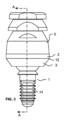
スクリュ装着式全方向マルチユニットアバットメントの利点を提供する為のオプションを例示するように、本開示には複数の実施形態が含まれる。図1及び2は、四つの部品、つまりアバットメントベース1、スイベルマウント2、スイベルベース3、そしてロックスクリュ4を具備する全方向マルチユニットアバットメント100の一実施形態の分解図を示している。図1及び図2の分解図には、代表的なチタンベース5と補綴スクリュ6も示されている。この全方向マルチユニットアバットメントアセンブリ100は、貴金属及び非貴金属と合金、セラミック、及び高強度エンジニアリングポリマー(例えば、PEEK、PEI)を含めて、インプラントアバットメントシステムの為のチタン又は他の適当な材料、或いは上述の材料の組み合わせから作られ得る。不要な生体成長又は事前癒合を防止するように、部品の表面又はその間の空間には処理、コーティング、又はゲルが追加され得る。図3は、補綴スクリュ6を除いた図1及び2の要素を線形配向で示す。図4は、図3の長手断面指示線A‐Aに沿った図3のアセンブリの内部特徴を示している。図4では例示を目的としてチタンベース5の存在が示されていることに注意していただきたい。チタンベース5は最終的に補綴物(不図示)に保持され、図6に示されている補綴スクリュ6を使用して全方向マルチユニットアバットメントに装着される。補綴スクリュ6は永久的なスクリュであるか、同じ所有者による米国特許11,311,354号と継続性により関連性を持つ他の出願とに記載されているタイプの一時的な締結具であってよい。図6は、線形構成における図1及び2のアセンブリの斜視図である。図5は、約30度傾斜した実施形態の側面図である。図7~9は、インプラントへの本実施形態の装填及び調整の多様な段階を示す。
To illustrate the options for providing the benefits of a screw-mounted omnidirectional multi-unit abutment, multiple embodiments are included in the present disclosure. Figures 1 and 2 show an exploded view of one embodiment of an omnidirectional
アバットメントベース1は、直径およそ3.25mmであってアバットメントベース駆動特徴10を近位端部に備えるボール又は球形部分13を含む。図示されているように、駆動特徴は、ボール部分13の上部で長手軸線を中心とするT5サイズのヘクサロビュラ内部(トルクス)駆動特徴ソケットであり得る。他のタイプの駆動ツールが使用されてもよい。アバットメントベース1の遠位端部は、患者の顎骨に固着されたインプラント16の雌ねじへの装着の為のねじ部分14である。全方向マルチユニットアバットメントの発明概念は多様なアバットメントとの界面に適応化され得るので、インプラント16と下顎又は上顎骨へのその装着部は本開示では概略的に記載される。雌ねじを備える図7に図示の汎用インプラント16は非常によく見られる設計であるが、アバットメントベース装着部14と嵌着部21とは他のインプラントに順応するように適応化され得る。
The
スイベルベース3は、開口部19と、アバットメントベース1のボール部分13の湾曲と本質的に適合するサイズ及び形状を持つ内部湾曲部分15とを含む。図示されているスイベルマウント2は、ロックスクリュ4の外ねじ9への装着の為の内ねじ20を含む。スイベルマウント2は、補綴スクリュにより全方向マルチユニットアバットメント100に取り付けられた時にチタンベース5を支持及び配向する為のチタンベース嵌着特徴22も含む。スイベルマウントは、レンチなどのツールを装着してチタンベース5の組立を補助するか、その方位配向(不図示)を制限するのに使用され得る嵌合特徴11を任意で含み得る。チタンベースとインプラントアバットメントとの整合的嵌合特徴によりチタンベースの配向を制限することは、単歯クラウンに有用な一般的技術である。本明細書の全方向マルチユニットアバットメント100の実施形態は、非円筒形の対称的なチタンベースの方位配向を固定することにより、詳細には記載されない整合アバットメント取付面により単歯補綴物に容易に適応し得る。
The
アバットメントベース1のボール部分13は、アバットメントベーススクリュねじ部分14がスイベルベース開口部19に延在する状態でボール部分13の周りにスイベルシェルを構成するスイベルベース3とスイベルマウント2との間に把持され得る。この挿入プロセスの為に、開口部19はアバットメント嵌着突部21より大きくなければならない。スイベルベース3とスイベルマウント2とは、ボール13の周りへの配置の後で例えばレーザによる連続溶接又はスポット溶接により界面接合部12で接合されてベースアセンブリ101を形成することが好ましい。この接合技術では、短距離にわたって肉薄シェルの強固なアセンブリが設けられるが、ボール部分13をシェル内に把持するのに他の接合技術が使用されてもよい。図4の断面図に示されているように、組立済みのスイベルベース3及びスイベルマウント2の内部湾曲15と開口部19との機械的設計は、接合後にアバットメントベースのボール部分13がスイベルシェルから脱落するのを防止するように設計され得る。アバットメント嵌着突部21における開口部19の相対的なサイズ及び形状とアバットメントベース1のサイズ及び形状は、可能な傾斜範囲を決定する。概して、スイベルベース開口部19とスイベルマウントの内ねじ20の小径又は幅の両方がボール13の幅より小さい場合には、ロックスクリュ4無しでボール13がシェル内に把持される。
The
図示されているロックスクリュ4は、スイベルマウント2の内ねじ20と嵌合する外ねじ9を有する。これらのねじは、例えば、m3×0.35サイズであり得る。ロックスクリュ4はまた、補綴スクリュ6を装着する為の内ねじ7と、ロックスクリュ4をスイベルマウント2に締結するツール装着部の為の内部駆動特徴8とを有する。代替的な補綴スクリュサイズは、m1.4×0.3ねじ、m1.6×0.35、UNF1‐72等を含む。駆動特徴8は、トルクスT5又はT6、0.035”から0.050”の六角又は四角ドライバ、或いは類似サイズの直線又は星型ドライバを含む一般的な歯科ドライバを収容するソケットであり得る。図示されているように、内ねじ7と駆動特徴8とは、ロックスクリュの長手軸線に沿って部分的重複部を有する。これは設計上の選択である。完全な軸方向重複あるいは軸方向重複無しは、他の設計オプションである。
The locking
スイベルベース3は、ロックスクリュ4が締結された時に球形ボール特徴13のセグメントと嵌合するように構成されている。示されている図及び断面は、図5及び8に示されているようにスイベルベース及びマウントが30度円錐体内のどこかに配置及び回転される実施形態を例示している。許容される調整の傾斜規模及び配向は設計上の選択であるが、30度の傾斜は大抵の臨床用途において概ね充分である。この実施形態に示されているように、スイベルベース開口部19とスイベルマウント2のねじ20の開口部とは、ボール部分13の直径より小さい。この事例で、アバットメントベース13のボール部分は、スイベルベース3とスイベルマウント2とが相互に装着された時にこれら二つの部品により緩く把持され得る。すなわち、図示されている実施形態でボール部分13を把持するシェルを設けるようにロックスクリュ4がスイベルマウント2に装着される必要はない。これは設計上のオプションであって、本開示の発明概念による恩恵を受ける為の要件ではない。
The
チタンベース5を含めたこの全方向マルチユニットアバットメント実施形態の図4の断面図は、要素間の好ましい幾何学的関係の利点の幾つかを例示するのに使用され得る。示されているように、スイベルベース3とスイベルマウント2とロックスクリュ4とにより形成されるシェルの動作範囲の全体でボール部分13は球形である。開口部に近接したスイベルベース3と、アバットメント嵌着部21の近くのアバットメントベース1の表面61との干渉による傾斜範囲制限は、図5及び図9に角度bと記されている。スイベルマウント2の内部湾曲は、ボール部分13のものと本質的に同じである。ロックスクリュ4は、接触エリアでボール13と同じ湾曲を本質的に有する。スイベルマウント2の内部湾曲15は、好ましくはボール13の湾曲より若干大きい。その結果、ロックスクリュ4が締結される時に、ボール部分13は、スイベルベース3の内部湾曲15、そしてロックスクリュ4の対応の内部湾曲と接触している。スイベルマウント2の内部湾曲が大きいので、ロックスクリュ4が充分に締結された時にはボールと接触しない。こうして、全方向マルチユニットアバットメントアセンブリの内部への生物学的汚染の侵入の阻止を助けるように、ボールに対するスイベルベースの一貫した連続的円形密閉が設けられる。図4の線形構成で、ロックスクリュ4はボール部分13との同等の円形密閉を設ける。図9の最大傾斜状態で図示されているように、ボールに対するスイベルベース3の連続密閉が維持される。しかしながら、アバットメント駆動特徴10があるので、ボール13に対するロックスクリュ4の密閉は連続的ではない。しかしながら、チタンベース5と補綴スクリュ6とが全方向マルチユニットアバットメントに適用される時には、アバットメント駆動特徴10が効果的に密閉される。
The cross-sectional view of FIG. 4 of this omnidirectional multi-unit abutment embodiment including the
ボール13に対する中空ロックスクリュ4の比較的大きなリング状接触は、中実のセットスクリュの集中的な接触よりも広いエリアにわたってクランプ力を分配する。ボール13に対するスイベルベースの接触・整合湾曲15を拡大すると、部品がチタン製である時にスイベルベース3又はスイベルマウント4を保持することなく25Ncm超でのロックスクリュ4の締結を可能にするのに充分な摩擦把持が得られると判断されている。比較的広い接触エリアは、集中的な中実セットスクリュと比較してクランプによるボール13の歪みも最小化し、こうしてボール13の幾何学形状の歪みによる干渉を伴わずに傾斜又は方位角度の再配置を容易にする。またロックスクリュ4の比較的大きな外径により、補綴スクリュ6のねじの幅に匹敵する駆動ツールサイズを持つロックスクリュ4にトルクを印加する為の機械的強度に充分な厚さが内ねじ7と外ねじ9との間に設けられる。
The relatively large ring-like contact of the
比較的大きなロックスクリュ4では、充分な数のロックスクリュねじ8がスイベルマウントの内ねじ20と嵌合してボール13への安定したクランプ力が得られる。スイベルマウント2とスイベルベース3との間の接合部12にもねじ(不図示)が使用され得るが、図4に示されている相対的サイズと同等の強度を与えるのに充分な壁厚と嵌合ねじ奥行とを有するように全方向マルチユニットアバットメントの直径を増加させる必要があるだろう。しかしながら、ロックスクリュ4の過剰トルクを防止することが望ましい場合には、閾値トルクに達した時に分離を起こすようにスイベルマウント2とスイベルベース3との間のスクリュねじの限定的な嵌合が使用され得る。トルク制限についての他のオプションは、上に記載された好適な溶接接合部強度の調整、スイベルマウントでの開口部19のサイズの増加、及び/又は、低いトルク抵抗を有する意図的に薄い壁区分を開口部19に近接したスイベルベースに取り入れることを含む。設計による意図的な不具合は全方向マルチユニットアバットメントの損失という結果を生じる可能性があるが、補綴物又はインプラント保持の将来的な不具合を生じる過剰応力についてこれは好ましい。
For a relatively
中空型のロックスクリュ4と図4に示されている駆動幾何学形状とは、歯科システムの装填及び維持における利点を提供する。スイベルベース3がスイベルマウント2に装着されてベースアセンブリ101を形成した後に、スイベルマウント2とスイベルベース3とにより形成されたシェル部分によりインプラントベースのボール部分13が把持される。ロックスクリュ4がスイベルマウント2へ差し込まれ、これを固着するのに充分だがボール部分13とは接触しないように回転されると、全方向マルチユニットアバットメントアセンブリ100が形成される。全方向マルチユニットアバットメントアセンブリの上部と図3及び4に示されているように共通軸線で整合された部品とに、チタンベース5が任意で設置される。アバットメントベース1とスイベルベース3とスイベルマウント2とロックスクリュ4との装填及び配向の間には、チタンベース5が所定箇所にある必要はない。こうして整合されると、チタンベース5とロックスクリュ4とに駆動ツール17が挿入されて、図7に図示されているようにアバットメントベース1の駆動特徴10と嵌合する。アバットメントベース駆動界面10と嵌合する為にロックスクリュ4を貫通した後に駆動ツール17をわずかに回転させる必要があり得ることに注意していただきたい。好ましくは駆動ツール17とアバットメントベース駆動特徴10との嵌合フィットは、図7に示されているように、全方向マルチユニットアバットメント100を駆動ツール17に残して全方向マルチユニットアバットメントアセンブリをインプラント16に載置するのに充分な摩擦を有する。弛緩方向でのロックスクリュ4のわずかなトルク付与は、この保持を助ける。駆動ツール17が回転されると、アバットメントベースねじ14がインプラント16と嵌合し、全方向マルチユニットアバットメントアセンブリがねじ込まれて、インプラント16に対するアバットメント嵌着部21の所望の嵌着が達成される。駆動ツールはアバットメントベース1とロックスクリュ4の両方と嵌合するので、これらの部品は同時に回転する。ロックスクリュ4の位置はアバットメントベース1に関して変化していないので、スイベルベース3とロックスクリュ4との間にボール部分13が挟持されていない。駆動ツール17からの回転力は、アバットメントベースねじ14をインプラント16へ更に深く押し込む。
The
インプラントと接触するアバットメントベースの嵌着部分21は、一定角度のアバットメントの嵌着幾何学形状と適合するように修正され得る。駆動特徴10は、インプラント16へのアバットメントベース1のねじ部分14の固着を可能にする。インプラントへのアバットメントベース1の締結は、アバットメント嵌着部21での所望の嵌着圧力が得られるまで進行し得る。代表的なトルク値は約30Ncmであるが、この値は採用されるインプラントシステムに依存し、これより高くても低くてもよい。補綴物の即時装填の為に、トルク値は、インプラントを顎骨へ装填するのに使用されるトルク値より小さくすべきである。
The abutment base's
図8に示されているように、アバットメントベース1がインプラント16に固着されると、図7の線形構成はもう必要とされない。補綴装着に望ましいチタンベース5を受容する為のスイベルマウント2の傾斜及び方位角度は、ロックスクリュ4へ挿入される駆動ツール18の動きにより選択され得る。駆動ツール18の回転により、ロックスクリュ4とスイベルベース3とがボール部分13をクランプし、全方向マルチユニットアバットメント100の角度をロックする。ロックスクリュ4が締結されている間にロックスクリュ及びスイベルベースが回転するのを防ぐように、嵌合特徴11が含まれ得る。小孔又はスプラインなど他の嵌合特徴も、この目的の為の回転防止又は方位角選択特徴として使用され得る。単歯補綴物の事例では、チタンベースの回転固定特徴と嵌合するスイベルマウント2の選択特徴により、チタンベースの方位角度が選択されて、ロックスクリュ4を締結する間、保持される。回転防止特徴と嵌合して18と類似した駆動ツールを含む同軸の二部ツールが、アバットメントベース1のボール部分13の位置にスイベルマウント2及びロックスクリュ4を配向及び締結するのに使用され得る。図5の配置構成に含まれるチタンベース5を設けることは、方位角選択に便利であり得る。
8, once the
一時的と最終的の両方の補綴物において、ロックスクリュ4の駆動特徴7は好ましくはチタンベース5からアクセス可能である。こうして、時間と共に緩んだ場合にロックスクリュ4を適切な配向に移動させて再びトルク付与し、パッシブフィットを向上させるように微調整を行ない、複数の全方向マルチユニットアバットメント100のうち一つの全方向マルチユニットアバットメント100を交換して再び整合させることができる。図7aの挿入図に示されている駆動ツール寸法d1と図8aの挿入図に示されている駆動ツール寸法d2との比較から、図8に示されている駆動ツール18は図7の駆動ツール17より大きい。これは必須ではない。二つの異なるサイズ、例えばアバットメントベース1を駆動する為のT5ドライバ17とロックスクリュ4を固着する為のT6ドライバ18とを使用することの利点は、アバットメントベースを駆動する間にロックスクリュ4に追加の間隙が生じることである。アバットメントベース1を駆動するのに使用されるトルクがロックスクリュ4に使用されるトルクより高くなるように選択され得るので、駆動ツール17を備える第1トルクレンチと駆動ツール18を備える第2トルクレンチとは、所望のトルクが確実に得られるのを助ける。言うまでもなく、図7に示されているように組立済みの全方向マルチユニットアバットメント100をインプラント16に装填する為に、駆動ツール17のサイズ及び形状はロックスクリュ4を貫通するものでなければならない。示されているロックスクリュ内部駆動界面8はロックスクリュ4の遠位側までは延在しないので、図8の駆動ツール18がロックスクリュ4を貫通することが妨げられる。これは設計上の選択である。
In both the temporary and final prostheses, the
一部の開業医は、所望の所定トルクがインプラントベース1及びロックスクリュ4に印加されるのはいつかを判断するのに、客観的な校正済みツールの代わりに、経験による身体感覚を使用することを選び得る。アバットメントベース駆動界面10とロックスクリュ駆動界面8とが同じサイズ及び形状である場合には、駆動ツール17及び18に一つのツールが使用され得る。この事例では、図7のようにアバットメントベース1をインプラント16へ押し込んだ後に、ロックスクリュ4を回転させることによりアバットメントベースを再配置して全方向マルチユニットアバットメント100の位置をロックする前に、アバットメントベース駆動界面10と脱嵌合させるのに充分なだけ駆動ツール17が抜出されるだけでよい。校正による異なるトルクが望ましい場合には、同じ駆動ツールチップサイズに二つの異なるレンチが使用されるだろう。一部の開業医は、両方のトルク付与プロセスステップの為に全方向マルチユニットアバットメントへ駆動チップが挿入されたままにし、トルクレンチセットを異なる値に切り替えることを選び得る。駆動ツール17の回転軸線は駆動ツール18と概ね異なっているので、アバットメントベース1とロックスクリュ4とに同じトルク規模を使用することは許容可能である。二つの異なるトルク設定の間で切り替える為の押しボタン又は他のセレクタを有するトルクレンチが有用であり得る。自動選択は、例えば、ばね装填シースを高トルク機構と嵌合させるのに駆動ツールチップの軸線に沿った力を必要とすることにより、アバットメントベース駆動界面10と嵌合するのに、ロックスクリュ駆動界面8と比較して深い駆動ツール奥行の差が必要とされることに基づき得る。この事例では、所望であれば、滑動は生じ得るが低トルク設定で嵌合したままでもよい。
Some practitioners may prefer to use an experienced physical feel instead of an objective calibrated tool to determine when the desired predetermined torque is applied to the
図9は、チタンベース5を保持する補綴スクリュ6を含む全方向マルチユニットアバットメントアセンブリ100の断面図を示す。リフトオフプロセスによる補綴物へのチタンベース5の配置を容易にするように、引用された米国特許第11,311,354号に記載のような分離式締結具(不図示)で補綴スクリュ6が置き換えられてもよい。チタンベース5が補綴物に組み込まれた後でも、補綴スクリュ6を除去することによりロックスクリュ駆動界面8へのアクセスが可能であることに注意していただきたい。これは図9から図8へ構成を本質的に変化させる。この利点は、他の実施形態が提示された後により詳しく記載される。
Figure 9 shows a cross-sectional view of an omnidirectional
図1から図9に示されている実施形態の変形が、図10から図13に示されている。実用的設計の観点から見て、従来のアバットメント直径や嵌着高さ(第一実施形態におけるチタンベース5の嵌着面22とインプラント嵌着面21との間の距離)の制限、そして他の寸法制限を考えると、全方向マルチユニットアバットメント設計は、アバットメントベース30とボール又は球形特徴31とが最初は別々の構成要素である実施形態も含み得る。図1~9の実施形態において、ボールは直径がおよそ3mmである。およそ2.5mmの公称嵌着高さが図に示されている。
Variations on the embodiment shown in Figures 1-9 are shown in Figures 10-13. From a practical design standpoint, given the limitations of conventional abutment diameter and fit height (the distance between the
図10~13に図示されている第二実施形態は、図1~9に示されている全方向マルチユニットアバットメントアセンブリ100と同じインプラント16及びチタンベース5と共に作用するようにほぼ同じ寸法で示されている。アバットメント嵌着部42とチタンベースシート41との間の嵌着高さも同等である。主な相違は、二部アバットメントベース30の部分の間にスイベル32が把持されることである。図12のアバットメントベース30は、ステム部分34に装着される独立したボール部分31を具備する。例えば、必要なアバットメント直径にスイベルベースが干渉なくフィットしない事例では、個別部品31は有用であり得る。結果的に、図10から図13の実施形態は、アバットメントベースステム部分34の係合ポスト特徴35に装着される遠位取付孔46を含む駆動界面45を備えるボール31を含む。ボール31をスイベル32へ挿入した後に、圧入、熱収縮、レーザ溶接、接着剤、又はこれらの組み合わせなど、いずれかの形態の機械的嵌合により、ボール31がベースステム部分34に組み付けられる。例えば、ボール31は、ポスト34へ軽く圧入されて、界面35において小径のレーザ溶接が行われ得る。この方法は、ボールをベースに確実に接合する一方で、機械的な精密作業を最小化し、係合接合部35に隅肉を設け、この接合部を液体侵入から密閉する。
The second embodiment shown in Figures 10-13 is shown with approximately the same dimensions to work with the
図示されている実施形態において、スイベル32の内ねじ38の小径は、スイベルマウント32の内ねじ40へボール31が挿入されるのに充分なほど大きい。駆動界面45は、組立の為にボールを配向するのに使用され得る。スイベル32を把持してロックスクリュ33を装填及び締結した後に、ボール31は密閉面47でスイベル32と接触する。およそ17.5度の嵌着/干渉面が図12~13に図示されている。ロックスクリュ33も、界面48でボール31と接触する。表面性状、隆起部、リブのように、ボール31に対する係合面48,47のロック能力を高めるのに、様々な表面仕上げ及び機械的特徴が採用され得る。スイベル32をボールに把持するこのアプローチが、スイベル32がボール31から落下するのを防止することに注意していただきたい。スイベル32は、図1~9の第一実施形態のスイベルベース3と同様にボールの遠位面と接触するが、前出のスイベルマウント2のチタンベース嵌着部22により提供されるものと類似した既定の配向でチタンベース5を支持するチタンベース嵌着部41も設けられる。
In the illustrated embodiment, the minor diameter of the internal threads 38 of the
ロックスクリュ33は、第一実施形態のロックスクリュ4と類似している。これは、補綴スクリュねじ36と駆動ソケット特徴37と嵌着面48と外ねじ39とを内含する。ボール部分31の近位端部は、上に記載されたロックスクリュ4と類似したロックスクリュ33からアクセスされ得る駆動ソケット特徴45を含む。駆動特徴37を使用してロックスクリュ33が締結される時に、スイベル32はボール31の嵌着面47と嵌合し、こうしてロックスクリュ33により、インプラント軸線から30度まで離れた理想的な全方向配向と所望の方位角度でスイベル32を固定することができる。やはり、全方向マルチユニットアバットメントの装填及び配向の間に、チタンベース5が存在する必要はない。補綴スクリュねじ36及び駆動特徴45,37,44のサイズの適切な選択を通して、アバットメントベース30をインプラント(不図示)に締結するステップ、ロックスクリュ33によりスイベル32の配向をロックするステップ、そして補綴スクリュ44を締結するステップの三つのステップに単一の駆動ツールを利用することが可能である。例えば、駆動界面37,44,45がT5ソケット特性を有する場合には、ねじ36を備えるM1.6×0.35の補綴スクリュ43には一般的な単一のT5駆動ツールが使用され得る。言うまでもなく、この事例で、アバットメントベース駆動ソケット特徴45と嵌合する為に、ロックスクリュ駆動界面37はロックスクリュ33(不図示)に延在する必要はない。T5ドライバの為に除去されたM1.6補綴スクリュねじの部分は、補綴ねじを適切に保持する為の適正なねじ一体性を提供すると判断されている。他の標準及びカスタムのねじ及び駆動幾何学形状の組み合わせが単一の駆動ツールの使用を可能にするのに使用されてもよい。
The locking
ボール31をアバットメントベース30に組み付けることにより、インプラント嵌着箇所42におけるアバットメントベース20の幅は第一実施形態より大きくなり得る。第一実施形態において、アバットメントベース1のねじ端部14は、ボール部分13と接触するようにスイベルベース開口部19へ挿入された。スイベルマウント2をスイベルベース3に接合することにより、ボール部分13が把持された。この実施形態でスイベルベース3及びスイベルマウント2の特性を単体のスイベル32に融合することにより、スイベル32開口部の遠位端部の開口部によりアバットメントベースの遠位端部のサイズは制限を受けない。図10~13の実施形態では、スイベル32へ挿入されるボールがアバットメントベース30に接合され得るように、ロックスクリュ外ねじ39の小径はボール31の直径より大きくなければならない。図12と図4との比較は、こうしてスイベル32とロックスクリュ33との間のねじと嵌合する為の奥行が短くなる結果となることを示している。
By assembling the
ボール特徴を備えるアバットメントベースにスイベルシェル構成要素を把持する為の別のアプローチが、図14~16に示されている。この実施形態において、アバットメントベースアセンブリ101は、スイベル32と、テーパステム50を備えるボールとから製作され、ボールは、近位端部に駆動特徴45を、遠位端部にテーパ状ステム51を備えるボール特徴13を有する。テーパ状ステム51は、近位端部にテーパ状ソケット53を、遠位端部にアバットメントベーススクリュねじ14を有するベース52に接合される。テーパステム50を備えるボールの最大幅の部分は、ボール13の直径である。テーパ状ステム51をテーパ状ソケット53へ挿入する前にテーパ状ステム51をスイベル32の近位側へ挿入することにより、スイベル32が把持される。
Another approach to gripping a swivel shell component to an abutment base with a ball feature is shown in Figs. 14-16. In this embodiment, an
図15及び16は、アバットメントベースアセンブリ101を示す。上記のように、テーパ状ステム51とベース52とは多様な技術で接合され得る。しかしながら、界面63に溶接を含めることが好ましい。図16と図14の比較は、テーパ状ステム50を備えるボールのボール部分13がアバットメントベースボール31と比較して改良された構造安定性を有し得ることを示す。部品のサイズが小さいことと、所定位置にロックされた時に部品のスムーズな旋回動作及びタイトな密閉が望ましいことを考慮すると、これは重要であり得る。
Figures 15 and 16 show the
図14に示されているロックスクリュ49は、近位端部に近い外面に六角駆動特徴64を含むことにより前出実施形態のロックスクリュ4及び33と異なっている。この六角駆動特徴64は、間違った装填の除去を助けるように設けられている。例えば、補綴スクリュステム25がロックスクリュ4内で折れた場合には、全方向マルチユニットアバットメントを装填するのに使用される駆動ツール18が挿入されないようにロックスクリュ駆動界面8が塞がれ得る。破損ステム25の除去の代替案として、ロックスクリュ49を除去するように六角特徴64にレンチ(不図示)が適用され得る。言うまでもなく、全方向マルチユニットアバットメントにおいてチタンベース5が所定位置にある状態で、これらの六角特徴64は概ねアクセス可能でない。その結果、全方向マルチユニットアバットメント配向の整合及びロックを補助してパッシブフィットを向上させる為に補綴物に埋設されたチタンベースを使用するには、ロックスクリュ駆動界面37が好ましい。必要であれば、チタンベース5により被覆されていないので、塞がれたロックナット49の除去を補助するようにスイベル32の側面の平坦部11にレンチが適用されてもよい。
The locking
図17は、ロックスクリュ49の上面図である。外縁部にはロックスクリュ外ねじ39が設けられ、中心にはトルクス型として示されているロックスクリュ内部駆動界面8が設けられている。スクリュ内ねじ7の大径66(点線)及び小径円弧65が示されている。小径65は連続円ではなく、ロックスクリュ内部駆動界面8がロックスクリュ内ねじ7と軸方向に重複することによる一連の不連続円弧セグメントである。ロックスクリュ49がロックスクリュ内部駆動界面8とロックスクリュ49全体に延在する内ねじ7とを有することに注意していただきたい。言い換えると、充分に長い補綴スクリュねじ25と駆動ツール18の両方がロックスクリュ49の厚みを貫通できるように、ロックスクリュ49の厚さにわたって本質的に完全な軸方向重複が見られる。駆動ツール18が全方向マルチユニットアバットメント100の配向をロックするトルクを印加するのに利用可能であるロックスクリュ49の材料の量は、スクリュ内ねじ7の大径86及び小径65により囲まれた体積から、駆動ツール18(不図示)の為のロックスクリュ駆動界面8のソケットを設けるように除去された材料を引いたものに相当する。駆動ツール界面8のサイズ及び形状は、補綴ねじ6を保持する為の残りの内ねじ7の強度と、内ねじ7を損傷させる前に配向を固定する為のロックスクリュ49への最大トルク印加とを変化させるように修正され得る。
17 is a top view of the locking
図18は、代替的なロックスクリュ内部駆動界面54を備えるロックスクリュ49の上面図である。この駆動ツール界面49は、前に例示されたトルクス駆動ツール界面の6ローブに代わって4ローブを有する。より少ないローブとより顕著なローブ移行部とを有することの結果として図17と比較して多くの内ねじが保持されることを示すには、図17との視覚的比較で充分である。その結果、内ねじ7とロックスクリュ駆動界面54との軸方向重複の結果生じる機械的強度の低下を補うのに利用可能な材料及び幾何学的なトレードオフのオプションが設けられ、こうして全方向マルチユニットアバットメント100の最終的な整合及びロックが所定箇所において補綴物とともに行われ得る。
18 is a top view of a locking
図19は、図18のロックスクリュ49の為の4ローブ駆動チップ62と、整合する4ローブ駆動界面60を備えるアバットメントベース59とを示す。明瞭化の為、全方向マルチユニットアバットメント100の他の部品は示されていない。駆動チップ62はロックスクリュ49を貫通するサイズであるので、アバットメントベース59をインプラント16(不図示)へ押し込むのに使用され得る。駆動チップはチタンベース開口部23(不図示)を貫通するサイズであるので、ロックスクリュ49を回転させて、チタンベース5(不図示)が埋設されている補綴物(不図示)における全方向マルチユニットアバットメントの位置を固定することもできる。
Figure 19 shows a four-
図20は、スイベル32を把持するように組み立てられる二部アバットメントベース55の別の実施形態を示す。この実施形態では、ボール部分13とアバットメントベーススクリュねじ14とがアバットメントベースステム56に含まれる。アバットメントボールベースステムの遠位端部がスイベル32へ、そして使用されるアバットメント16の界面要件と適合する中空スリーブ57へ挿入される。スリーブ57は、ボール部分13の直径より大きい最大幅を有する。その結果、スリーブ57がアバットメントベースステム56に接合された時に、スイベル32が把持される。上述した様々な接合作業のいずれも使用され得るが、図22に示されているような界面58での溶接を含むことが好ましい。やはり図22に示されているのは、上記の組立プロセスの為の二つの重要寸法である。スイベル32の貫通開口部の最小直径「d」は、ボール部分の下方にあるアバットメントベースステム56の最大幅「c」より大きくなければならない。この実施形態と前出のものとの類似性故に、他の部品及び特性は記載されない。
20 shows another embodiment of a two-
ボールの多様な形態の雄ピン、アバットメントベースの雌ソケット、ボール又はアバットメントのねじポストなど、装着されたアバットメント接続アセンブリでスイベルをボールに把持する他の多くの方法が可能である。発明概念を具現化して最大の配向柔軟性を提供するように本質的に球形のボールが図示されているが、配向を意図的に制限するのに他の形状が使用されてもよい。例示された発明概念のうち一以上をやはり使用する係合界面が、提示されていない実施形態で目的を果たすように調整されてもよい。 Many other ways of gripping the swivel to the ball with the abutment connection assembly attached are possible, such as male pins of various configurations on the ball, female sockets on the abutment base, threaded posts on the ball or abutment. Although an essentially spherical ball is shown to embody the inventive concepts and provide maximum orientation flexibility, other shapes may be used to purposefully limit orientation. Engagement interfaces that also use one or more of the illustrated inventive concepts may be tailored to serve purposes in embodiments not shown.
図23は、第一実施形態の装填済み全方向マルチユニットアバットメント100の適用環境の断面を示す。インプラント16は、70として概略的に示されている患者の骨及び軟組織に装填されている。アバットメントベース1は、所望のトルクレベルまでインプラント16にねじ込まれている。この事例で、スイベルマウント4は、図8に匹敵する本質的にその最大能力まで傾斜している。チタンベース5は補綴物68に埋設されている。補綴物の咬合面72は概略的に72として示されている。チタンベース5はスイベルマウント4に嵌着しているが、ロックスクリュ界面8が補綴スクリュアクセス孔69を通って駆動ツール71にアクセス可能となるように補綴スクリュ6は除去されている。4ローブ駆動ツール71が図示されているが、第一実施形態について既に記載されているようにアバットメントベース1をインプラント16へ押し込むには、これより小さい駆動ツール(不図示)が必要とされるだろう。第一実施形態で述べられたように、補綴物が所定位置にある状態で全方向マルチユニットアバットメント配向に変更を加えることができると有益である。これをより詳細に記すのに図23が使用される。
23 shows a cross-section of the application environment of the loaded omnidirectional
図23には一つのインプラントのみが示されているが、複数のインプラントと係合する複数のチタンベースを補綴物が含むと、現場調整の利点が大きくなる。インプラント取付の為の補綴物の製作又は修正の間に、チタンベース位置の不確実性が蓄積され得る。これらのシフトの性質がランダムであるが故に、チタンベースの配向及び位置が互いに、そしてチタンベースを補綴物とともに配向するのに最初に使用されたアバットメントセットの位置から外れることがある。チタンベースが最初に完璧に配置された場合でも、患者の顎又は補綴物の形状は時間と共に変化し得る。図23に示されているように、補綴スクリュ6の除去により、ロックスクリュ4にアクセスして駆動ツール71で緩めることができる。咬合側72から補綴物68に再嵌着力を印加すると、埋設されたチタンベース5がチタンベース嵌着部22に押圧されることにより、全方向マルチユニットアバットメントの配向が訂正される。補綴物68への再嵌着力を維持しながら駆動ツール71でロックスクリュ4を締結すると、この配向がロックされる。そしてチタンベース5と補綴物68とを所定位置に固着させるように、補綴スクリュ6が再挿入及びトルク付与され得る。時間と共に緩んだかどうかを確認する為にロックスクリュ4へのトルクを点検することが望ましい場合には、補綴物68に埋設されたチタンベース5を通してこれが行われ得る。
Although only one implant is shown in FIG. 23, the advantages of on-site adjustment are greater when the prosthesis includes multiple titanium bases that engage multiple implants. During fabrication or modification of the prosthesis for implant attachment, uncertainty in the titanium base position can accumulate. Due to the random nature of these shifts, the orientation and position of the titanium bases can shift from each other and from the position of the abutment set that was originally used to orient the titanium base with the prosthesis. Even if the titanium base was initially perfectly positioned, the shape of the patient's jaw or the prosthesis can change over time. As shown in FIG. 23, removal of the
同様に、セット内の一つの全方向マルチユニットアバットメント100が壊れるか交換の必要がある場合には、補綴スクリュ6全てを除去した後に、チタンベース5が埋設された補綴物68が除去され得る。図8及び図7に示されている角度設定及びインプラント装着のプロセスを逆転させると、壊れた全方向マルチユニットアバットメントアセンブリ100が除去される。新しい全方向マルチユニットアバットメント100をインプラント16に装着するように図7のプロセスを反復すると、アバットメントベース1がインプラント16に固着される結果となるが、スイベルベース3とスイベルマウント2とロックスクリュ4とから成るシェルは緩められる。重力で移動しないように全方向マルチユニットアバットメントの配向を保持するにはロックスクリュ4への最小圧力で充分であるが、配向を変えるのに必要なのは最小の力の印加のみである。チタンベース5を補綴物68に嵌合させるのに充分なスイベルマウント4の大まかな配置と咬合側72から補綴物への手による圧力の印加とにより、新しく装填された全方向マルチユニットアバットメントが再配向されて、補綴物に既に装填されているチタンベースと整合される。そして図23に示されているように、チタンベース5の開口部23からロックスクリュ4が適切な位置へ締結され得る。ロックスクリュ6を締結する前に、新しく装填された全方向マルチユニットアバットメント100への整合圧力を維持するのに最初の全方向マルチユニットアバットメント100の補綴スクリュ6が使用されるかどうかは、任意である。
Similarly, if one omnidirectional
ロックスクリュ駆動界面8はチタンベース5及び補綴物68を通ってアクセス可能であるので、最初の装填時のパッシブフィットを向上させるように全方向マルチユニットアバットメントの配向を微調整するのに、ワンスクリュ・パッシブフィット検査手順の変形が使用されてもよい。補綴物68に装填されたチタンベース5の開口部23を通して全方向マルチユニットアバットメント100を再配向する能力を活用する為の多様なオプションが見られる。一つのアプローチでは、補綴スクリュ6の全てが除去される。補綴物68は所定箇所に残っているが、全方向マルチユニットアバットメントロックスクリュ4の全てが緩められ、そして幾らかの摩擦抵抗が設けられるが旋回滑動は防止するように指で締結される。指による適切な締結の為の実際のトルク値は、全方向マルチユニットアバットメントの構造及び表面仕上げに依存するが、概ね数Ncmより小さい。次に、補綴スクリュ6の全てが再装填され、推奨値までトルク付与される。このようにして、全方向マルチユニットアバットメントの各々の配向が補綴物68に一層密接に適合する。次に、単一の補綴スクリュ6が、その位置の全方向マルチユニットアバットメントのロックスクリュ4にアクセスする為に除去される。所定値までロックスクリュ4にトルク付与される。補綴スクリュ6が再挿入されて所定値までトルク付与される。これは、全方向マルチユニットアバットメントロックスクリュ4の全てが締結されて補綴スクリュ6の全てが締結されるまで反復される。
Since the locking
上記の微調整プロセスは、最初のパッシブフィットのレベルの詳細に応じて修正され得る。例えば、全方向マルチユニットアバットメントロックスクリュ4の幾つかのみを、他は最初の補綴物フィッティングでの係止点に固定されたままで、緩めることが望ましいこともある。これは、良好な咬合又は他の理由からパッシブフィットについていくらか妥協する必要があることの結果として生じ得る。或いは慣例的なワンスクリュ又はスクリュ抵抗検査の結果から、全方向マルチユニットアバットメントの部分集合のみの配向調整、或いは異なる調整順序が示唆され得る。いずれにしても、補綴物を所定箇所に置いたままで全方向マルチユニットアバットメントを配向及び固定する能力から、これらのパッシブフィットの改良が直接的に得られる。 The fine-tuning process described above may be modified depending on the specifics of the initial passive fit level. For example, it may be desirable to loosen only some of the omnidirectional multi-unit abutment locking screws 4 while others remain fixed at their anchoring points in the initial prosthesis fitting. This may result from the need to compromise somewhat on passive fit for good occlusion or other reasons. Alternatively, the results of a routine one-screw or screw resistance test may suggest alignment adjustment of only a subset of the omnidirectional multi-unit abutments, or a different alignment sequence. In any case, these passive fit improvements flow directly from the ability to orient and secure the omnidirectional multi-unit abutments while the prosthesis is in place.
全方向マルチユニットアバットメント100の上記実施形態が、既に品質保証されて商業的に成功しているチタンベース5及びねじインプラント16との適合性を持つように適応化されることが好ましい。このインプラントが従来の直線状アバットメントと共に上記実施形態で同じ患者に使用され得るので、広く利用可能なインプラントのねじ形成及び嵌着は在庫方程式を向上させる。それほど重要ではないが、広く利用可能なスクリュ装着式チタンベース5との適合性も利点として見なされる。しかしながら、上記実施形態の進歩性を備える特徴は、パッシブフィット改良又は装填効率及び上に記載の修理の為に発明概念を採用する新設計のインプラントに一体化されるか、これと作用するように適応化され得る。これらの発明概念は、スクリュ装着式でない補綴物と作用するように適応化されてもよい。これらの適応化は除外されるものではなく、本明細書に開示され、これらに適用されると広く解釈され得る請求の範囲に含まれる。米国特許第11,311,354号は、リフトオフプロセスにおける仮締結具を使用した補綴物への組み込みの為にチタンベースをアバットメントと整合させる為の多様なアプローチを含む。同一所有者による特許に図示されている仮締結具の基本設計は、上に記載の全方向マルチユニットアバットメント及びチタンベースと共に採用され得る。
It is preferred that the above embodiment of the omnidirectional
様々な実施形態は、発明を限定するのでなく開示された発明概念を例示する為に記載されている。発明概念を使用する更なる実施形態を作り出す為の一以上の実施形態の進歩性を備える要素と周知の材料、構成要素、及び歯学技術との組み合わせは、本開示の一部であると考えられる。 The various embodiments are described to illustrate the disclosed inventive concepts and not to limit the invention. Combinations of elements comprising the inventive step of one or more of the embodiments with well-known materials, components, and dental techniques to create further embodiments that use the inventive concepts are considered part of this disclosure.
1 アバットメントベース
2 スイベルマウント
3 スイベルベース
4 ロックスクリュ
5 チタンベース
6 補綴スクリュ
7 内ねじ
8 内部駆動特徴
9 外ねじ
10 アバットメントベース駆動特徴
11 嵌合特徴
12 界面接合部
13 ボール部分
14 ベース装着部
15 内部湾曲
16 インプラント
17 駆動ツール
19 ベース開口部
20 内ねじ
21 アバットメント嵌着突部
22 チタンベース嵌着特徴
23 チタンベース開口部
25 補綴スクリュステム
30 アバットメントベース
31 ボール
32 スイベル
33 ロックスクリュ
34 ステム部分
35 界面
36 補綴スクリュねじ
37 駆動ソケット特徴
39 外ねじ
40 内ねじ
41 チタンベース装着部
42 インプラント嵌着箇所
43 補綴スクリュ
44 駆動界面
45 駆動界面
46 遠位取付孔
47 嵌着面
48 嵌着面
49 ロックスクリュ
50 テーパステム
51 テーパ状ステム
52 ベース
53 テーパ状ソケット
54 内部駆動界面
55 二部アバットメントベース
56 アバットメントベースステム
57 中空スリーブ
58 界面
59 アバットメントベース
60 4ローブ駆動界面
61 アバットメントベース表面
62 4ローブ駆動チップ
63 界面
64 六角駆動特徴
65 小径
66 大径
68 補綴物
69 補綴スクリュアクセス孔
70 骨及び軟組織
71 4ローブ駆動ツール
72 咬合面
100 全方向マルチユニットアバットメント
101 ベースアセンブリ
1
Claims (20)
長手軸線を有するアバットメントベースであって、
ボール部分とアバットメントベース駆動界面とを具備する近位端部と、
前記インプラントへの装着の為のスクリュねじを具備する遠位端部と、
を具備するアバットメントベースと、
内面と外面とを有するスイベルシェルであって、前記遠位端部に近接するスイベル開口部と、前記近位端部のねじ開口部とを含むスイベルシェルと、
長手軸線を有するロックスクリュであって、
前記スイベルシェルの前記ねじ開口部との適合性を持つ外ねじを備える部分と、
前記補綴ねじシャフトと嵌合するサイズの内ねじを備える部分と、
ロックスクリュ駆動界面と、
を具備するロックスクリュと、
を具備し、
前記ロックスクリュの回転により、前記アバットメントベースの前記長手軸線と平行でない配向に前記ロックスクリュの前記長手軸線の配向を固定することが可能である、
システム。 A system for aligning and mounting a dental prosthesis to an implant by means of a prosthetic screw, the prosthetic screw having a head and a threaded shaft,
An abutment base having a longitudinal axis,
a proximal end having a ball portion and an abutment base drive interface;
a distal end having a screw thread for attachment to the implant;
An abutment base comprising:
a swivel shell having an inner surface and an outer surface, the swivel shell including a swivel opening proximate the distal end and a threaded opening at the proximal end;
A lock screw having a longitudinal axis,
a portion having external threads that are compatible with the threaded opening of the swivel shell;
a portion having internal threads sized to mate with said prosthetic screw shaft;
a lock screw drive interface;
A lock screw comprising:
Equipped with
Rotation of the locking screw can fix the orientation of the longitudinal axis of the locking screw in an orientation that is not parallel to the longitudinal axis of the abutment base.
system.
前記ボール部分が前記スイベルシェルの内側に緩く拘束されて前記アバットメントベーススクリュねじが前記スイベル開口部に延在する状態で前記アバットメントベースの周りの前記スイベルシェルに前記ロックスクリュを装着して、マルチユニットアバットメントアセンブリを形成することと、
前記アバットメントベース駆動界面と嵌合するように前記アバットメント駆動ツールチップを前記ロックスクリュへ挿入することと、
前記アバットメントベース駆動ツールとマルチユニットアバットメントアセンブリとを前記インプラントに載置することと、
前記アバットメントベース駆動ツールを回転させて前記アバットメントベースを第1トルクで前記インプラントに装着することと、
前記アバットメントベース駆動ツールを前記アバットメントベース駆動界面から脱嵌合させることと、
前記スイベルシェルを異なる配向に移動させることと、
前記ロックスクリュ駆動ツールを回転させて前記インプラント軸線に対する前記スイベルシェル軸線の配向を第2トルクに固定することと、
チタンベースを具備する補綴物を前記インプラントアバットメントシステムに載置することと、
補綴スクリュにより前記補綴物を前記インプラントアバットメントに装着することと、
を包含する方法。 13. A method for aligning and mounting a dental prosthesis to an implant by means of a prosthetic screw using the system of claim 1, comprising:
installing the locking screw into the swivel shell about the abutment base with the ball portion loosely constrained inside the swivel shell and the abutment base screw threads extending into the swivel opening to form a multi-unit abutment assembly;
inserting the abutment driving tool tip into the locking screw so as to mate with the abutment base driving interface;
placing the abutment base driving tool and multi-unit abutment assembly onto the implant;
rotating the abutment base driving tool to attach the abutment base to the implant with a first torque;
disengaging the abutment base driving tool from the abutment base driving interface;
moving the swivel shell to different orientations;
rotating the locking screw driving tool to fix the orientation of the swivel shell axis relative to the implant axis at a second torque;
placing a prosthesis having a titanium base on the implant abutment system;
Attaching the prosthesis to the implant abutment with a prosthetic screw;
The method includes:
軸線と第1ポスト端部と第2ポスト端部とを有するポストであって、前記ロックスクリュへのスクリュ装着の為に前記第1ポスト端部がねじ形成される、ポストと、
キャップであって、前記第2ポスト端部に装着されるキャップと、
を具備し、
前記キャップに回転力を印加して前記第1ポスト端部を前記ロックスクリュにねじ込むことにより前記チタンベースを前記スイベルシェルに保持するように前記仮整合締結具が構成され、前記第1ポスト端部と反対向きの解除力を通して前記キャップが前記ポストから分離可能である、
請求項12の方法。 The titanium base is assembled to the prosthesis using a lift-off process with temporary fasteners, the temporary fasteners being
a post having an axis and a first post end and a second post end, the first post end being threaded for screw attachment to the lock screw;
a cap attached to the second post end;
Equipped with
the provisional alignment fastener is configured to hold the titanium base to the swivel shell by applying a rotational force to the cap to thread the first post end onto the locking screw, and the cap is separable from the post through a release force directed against the first post end.
13. The method of claim 12.
ボール・シェルアセンブリであって、
前記インプラントへのスクリュ装着の為のアバットメント駆動界面を具備するベースであって、ボールを有する第1端部と、長手軸線を持つねじポストを備える第2端部とを具備するベースであり、歯科インプラントに所定のトルクでねじ込まれるように前記ねじポストが設計される、ベースと、
内面と外面とを有するシェル部分であって、開口部を備える第1端部を有するシェル部分であり、第2端部がロックスクリュを有し、前記ベースポストの前記ねじ部分が前記開口部に延在する状態で前記ボールが前記シェル部分の内側に把持される、シェル部分と、
を具備するボール・シェルアセンブリと、
チタンベースであって、近位端部の開口部と、既定の位置で前記シェル部分の外側に取り付けられるように設計された遠位端部の界面とを具備するチタンベースと、
前記アバットメント駆動界面と前記ロックスクリュとを嵌合させるように設計された一以上の駆動ツールであって、少なくとも一つの駆動ツールが、前記ロックスクリュと嵌合するように前記チタンベース開口部への挿入が可能であり、前記ロックスクリュの締結により前記ボールに圧力が印加されて前記シェルの配向が固定される、一以上の駆動ツールと、
を具備する、
システム。 1. A system for aligning and attaching a dental prosthesis to an implant using a multi-unit implant abutment, the multi-unit implant abutment comprising:
1. A ball and shell assembly comprising:
a base having an abutment driving interface for screw attachment to the implant, the base having a first end having a ball and a second end having a threaded post with a longitudinal axis, the threaded post being designed to be screwed into the dental implant with a predetermined torque;
a shell portion having an inner surface and an outer surface, the shell portion having a first end with an opening and a second end having a locking screw, the ball being captured inside the shell portion with the threaded portion of the base post extending into the opening;
a ball and shell assembly comprising:
a titanium base having an opening at a proximal end and an interface at a distal end designed to be attached to the outside of the shell portion at a predetermined location;
one or more drive tools designed to mate with the abutment drive interface and the locking screw, at least one drive tool being insertable into the titanium base opening to mate with the locking screw, and tightening the locking screw applies pressure to the ball to fix the orientation of the shell;
Equipped with
system.
前記チタンベース開口部より大きい幅を持つヘッド部分と、
前記チタンベース開口部より小さい幅を持つねじシャフト部分と、
を具備し、
前記ロックスクリュが、前記補綴スクリュのねじを受容する為のねじを含む、
システム。 16. The system for aligning and attaching a dental prosthesis to an implant using a multi-unit implant abutment according to claim 15, further comprising a prosthetic screw, the prosthetic screw comprising:
a head portion having a width greater than the titanium base opening;
a threaded shaft portion having a width smaller than the titanium base opening;
Equipped with
the locking screw includes threads for receiving threads of the prosthetic screw;
system.
前記補綴スクリュシャフトと嵌合する為の内ねじと、
前記ロックスクリュを締結する為のツールを受容する為の駆動界面と、
を具備する長手開口部を前記ロックスクリュが具備する、
システム。 20. A system for aligning and attaching a dental prosthesis to an implant using the multi-unit implant abutment of claim 17, comprising:
an internal thread for mating with the prosthetic screw shaft;
a drive interface for receiving a tool for tightening the lock screw;
the lock screw having a longitudinal opening comprising
system.
Applications Claiming Priority (3)
| Application Number | Priority Date | Filing Date | Title |
|---|---|---|---|
| US202163196227P | 2021-06-03 | 2021-06-03 | |
| US63/196,227 | 2021-06-03 | ||
| PCT/US2022/032234 WO2022256699A1 (en) | 2021-06-03 | 2022-06-03 | Omnidirectional multi-unit abutment system for screw-attached dental prostheses |
Publications (2)
| Publication Number | Publication Date |
|---|---|
| JP2024524840A true JP2024524840A (en) | 2024-07-09 |
| JP7630017B2 JP7630017B2 (en) | 2025-02-14 |
Family
ID=84285674
Family Applications (1)
| Application Number | Title | Priority Date | Filing Date |
|---|---|---|---|
| JP2023573053A Active JP7630017B2 (en) | 2021-06-03 | 2022-06-03 | Omnidirectional multi-unit abutment system for screw-mounted dental prostheses |
Country Status (9)
| Country | Link |
|---|---|
| US (2) | US12023220B2 (en) |
| EP (1) | EP4312872B1 (en) |
| JP (1) | JP7630017B2 (en) |
| KR (1) | KR102673153B1 (en) |
| CN (1) | CN117500453B (en) |
| AU (1) | AU2022286486B2 (en) |
| CA (1) | CA3215615C (en) |
| IL (1) | IL309005B2 (en) |
| WO (1) | WO2022256699A1 (en) |
Families Citing this family (9)
| Publication number | Priority date | Publication date | Assignee | Title |
|---|---|---|---|---|
| US12303352B2 (en) | 2021-06-03 | 2025-05-20 | Full Arch Solutions, Llc | Omni-directional multi-unit abutment dental systems |
| KR102673153B1 (en) | 2021-06-03 | 2024-06-05 | 풀 아치 솔루션즈, 엘엘씨 | Omnidirectional multi-unit abutment system for screw-mounted dental prostheses |
| KR102363645B1 (en) * | 2021-07-26 | 2022-02-15 | 장천석 | Abutments for implants with connector to reduce the diameter of the screw hole |
| US20240164873A1 (en) * | 2022-11-20 | 2024-05-23 | Jeremy Lane Thompson | Adjustable-angle multi-unit abutment |
| EP4431054B1 (en) * | 2023-03-15 | 2026-04-22 | Talladium España, S.L. | Internal transepthelial abutment |
| WO2024211923A2 (en) * | 2023-04-07 | 2024-10-10 | Thompson Jeremy Lane | Adjustable-angle multi-unit abutment |
| EP4709317A2 (en) * | 2023-06-22 | 2026-03-18 | Full Arch Solutions, LLC | Self-aligning multi-unit abutment system for dental prostheses |
| WO2025191306A1 (en) * | 2024-03-13 | 2025-09-18 | Khoury Nikola | A tibase for a multi unit abutment |
| SE2450361A1 (en) * | 2024-04-05 | 2025-10-06 | Bmc Dental Ab | A fastening system |
Citations (7)
| Publication number | Priority date | Publication date | Assignee | Title |
|---|---|---|---|---|
| AT375012B (en) * | 1982-09-20 | 1984-06-25 | Buermoos Dentalwerk | DENTAL IMPLANT IMPLANT |
| JPS648963A (en) * | 1987-03-16 | 1989-01-12 | Vent Plant Corp | Embedding screw type dental implant |
| JP2551779B2 (en) * | 1986-09-04 | 1996-11-06 | ベントープラント コーポレーション インク | Improved implantable screw dental implant |
| DE19653229A1 (en) * | 1996-12-20 | 1998-06-25 | Manfred Stroppe | Implant and insert for human jaw or tooth |
| EP2647347A1 (en) * | 2012-04-02 | 2013-10-09 | Terrats Mecanizados S.L. | Prosthetic attachment |
| JP2014516731A (en) * | 2011-06-08 | 2014-07-17 | ゼスト、アイピー、ホールディングス、リミテッド、ライアビリティー、カンパニー | Fixed removable dental attachment device, combination and method of using the device and combination |
| US20200107914A1 (en) * | 2018-10-09 | 2020-04-09 | Brandon Dale Kofford | Screw-attached Pick-up Dental Coping System and Methods |
Family Cites Families (60)
| Publication number | Priority date | Publication date | Assignee | Title |
|---|---|---|---|---|
| SE328961B (en) | 1970-03-25 | 1970-09-28 | Aga Ab | |
| US4070122A (en) | 1976-09-13 | 1978-01-24 | Tecumseh Products Company | Ball and socket joint and method of making |
| DE3531389A1 (en) | 1985-09-03 | 1987-03-05 | Kirsch Axel | ENOSSAL IMPLANT |
| US4932868A (en) | 1986-09-04 | 1990-06-12 | Vent-Plant Corporation | Submergible screw-type dental implant and method of utilization |
| US4832601A (en) | 1987-12-04 | 1989-05-23 | Hall Surgical | Adjustable support for a prosthetic tooth and method |
| US4988297A (en) | 1988-03-01 | 1991-01-29 | Implant Innovations, Inc. | Alignment corrector for dental implants |
| US4907969A (en) | 1988-04-14 | 1990-03-13 | Ward Whitley S | Universal dental prosthesis retention system |
| FR2655534B1 (en) | 1989-12-12 | 1997-10-24 | Patrick Peltier | DENTAL IMPLANT. |
| SE466935B (en) | 1990-09-04 | 1992-05-04 | Oscar Wilje | DEVICE FOR ANCHORING OF PROSTHESIS |
| US5133662A (en) | 1991-09-03 | 1992-07-28 | Metcalfe Edwin R | Tooth implant device |
| GB9124417D0 (en) | 1991-11-16 | 1992-01-08 | Rosa Michael F | Universal joint for dental abutment implant |
| DE9202656U1 (en) | 1992-02-29 | 1992-04-23 | ZL Microdent-Attachment GmbH, 5805 Breckerfeld | Implant construction |
| DE4224785C2 (en) | 1992-07-27 | 1997-04-30 | Imz Fertigung Vertrieb | Endosseous dental implant for a fixed denture and insertion tool |
| US5302125A (en) | 1992-10-22 | 1994-04-12 | Kownacki Charles D | Dental prosthetic implant |
| US5873721A (en) * | 1993-12-23 | 1999-02-23 | Adt Advanced Dental Technologies, Ltd. | Implant abutment systems, devices, and techniques |
| US5417570A (en) | 1994-01-03 | 1995-05-23 | Zest Anchors, Inc. | Dental anchor assembly |
| US5599185A (en) | 1994-09-28 | 1997-02-04 | Greenberg Surgical Technologies, Llc | Dental implant healing abutment |
| FR2727307B3 (en) | 1994-11-25 | 1996-12-20 | Claude Segura | CONNECTING DEVICE FOR DENTAL PROSTHESIS ADAPTABLE ON NATURAL OR ARTIFICIAL ROOTS |
| US6287115B1 (en) | 1998-11-17 | 2001-09-11 | L. Paul Lustig | Dental implant and tool and method for effecting a dental restoration using the same |
| DE19959366A1 (en) | 1999-12-09 | 2001-06-13 | Stefan Wintermantel | Implant structure for enossal (in-bone) tooth implant is connectable to implant by screw and comprises post together with connecting part applicable to implant basal to post |
| DE10133932B4 (en) | 2001-06-16 | 2007-12-20 | Kaun, Jürgen | dental implant |
| KR100428934B1 (en) * | 2001-10-11 | 2004-04-29 | 주식회사 덴티움 | Impression coping for implant operation |
| US6843653B2 (en) | 2002-06-04 | 2005-01-18 | Joseph Carlton | Dental implant |
| US6981871B2 (en) | 2002-07-05 | 2006-01-03 | Zest Anchors, Inc. | Dental attachment assembly and method |
| EP1547543A1 (en) | 2003-12-23 | 2005-06-29 | Steffen Dr. Heitland | Abutment for dental implants |
| US7214063B2 (en) | 2004-07-29 | 2007-05-08 | Yechiel Cohen | Implant system particularly useful for fixing dental prostheses to bone |
| US20080261174A1 (en) | 2007-04-23 | 2008-10-23 | Gittleman Neal B | Expanding Ball Lock Oral Prosthesis Alignment Apparatus |
| EP2417928B2 (en) | 2007-09-17 | 2019-03-06 | Straumann Holding AG | Connecting assembly between a dental implant and an abutment |
| US20100151420A1 (en) * | 2008-12-11 | 2010-06-17 | Ranck Roger S | Fixtures for dental implants |
| US20100291507A1 (en) | 2009-05-13 | 2010-11-18 | Custom Spine, Inc. | Polyaxial Dental Implant |
| US8142193B2 (en) * | 2009-06-25 | 2012-03-27 | Bar Shalom Eliezer | Compound angular joint for connecting an abutment to a dental implant in a predefined angle |
| EP2696800B1 (en) | 2011-04-15 | 2019-03-27 | Jbsg Management LLC | Polyaxial dental implant system |
| ITUD20110065A1 (en) | 2011-04-27 | 2012-10-28 | 2 Al S A S Di Amadio Alessandra & C | DENTAL DEVICE FOR THE POSITIONING OF A DENTAL PROSTHESIS |
| KR101570279B1 (en) | 2011-05-16 | 2015-11-18 | 헤레우스 쿨제르 노르딕 아베 | Dental superstructure and method for manufacturing the same |
| DE102011086711A1 (en) | 2011-11-21 | 2013-05-23 | Promedia A. Ahnfeldt Gmbh | Anchoring device for securing orthodontic wires or orthodontic appliances for orthodontic corrective treatments |
| KR200471489Y1 (en) | 2012-04-04 | 2014-02-28 | 왕제원 | Freely adjust the angle and position adjustable attachment for fixing dentures |
| GB2506634A (en) * | 2012-10-04 | 2014-04-09 | William Duncan Robertson | A joint consolidator |
| BR102012029369A2 (en) | 2012-11-19 | 2014-09-23 | Esteban Xam-Mar Mangrane | IMPROVEMENTS INTRODUCED IN DYNAMIC PILLAR ASSEMBLY |
| US9452029B2 (en) | 2012-12-11 | 2016-09-27 | Zest Ip Holdings Llc | Fixed hybrid dental attachment device and methods of using same |
| JP6346903B2 (en) | 2013-01-07 | 2018-06-20 | エルスナー、エドヴィンELSNER, Edvin | Dental device fixation unit elastically fixed in the implant and / or dental device fixation unit fixed in the implant allowing optional angular position adjustment |
| WO2015040250A1 (en) | 2013-09-23 | 2015-03-26 | Esteban Xam-Mar Mangrane | Interface element for dental prostheses |
| KR101386560B1 (en) * | 2013-11-21 | 2014-04-17 | 김윤자 | Dental implant |
| US9687320B2 (en) | 2014-02-17 | 2017-06-27 | Sterngold Dental, Llc | Dental device for anchoring a denture to an implant |
| KR101407224B1 (en) | 2014-03-06 | 2014-06-17 | 왕제원 | A attachment for fixing dentures |
| US9033709B1 (en) | 2014-06-06 | 2015-05-19 | Zest Ip Holdings, Llc | Dental attachment assembly cap and method of use |
| US9931181B2 (en) | 2014-07-22 | 2018-04-03 | Zest Ip Holdings, Llc | Fixed hybrid dental attachment assembly and methods of use |
| US9827074B2 (en) | 2014-07-22 | 2017-11-28 | Zest Ip Holdings, Llc | Fixed hybrid dental attachment device and methods of use |
| WO2016139671A1 (en) | 2015-03-04 | 2016-09-09 | Alintech Ltd. | Dental implant and abutment |
| US9320577B1 (en) | 2015-03-27 | 2016-04-26 | King Saud University | Joint assembly for dental implant abutment |
| HU231077B1 (en) | 2015-04-21 | 2020-06-29 | Elsner Global Llc | Assembly to fasten a dental structure to a dental implant |
| IL244461A (en) | 2016-03-06 | 2017-06-29 | Jacobsen Hagay | Adaptor for adjustably mounting a structure onto a biological base |
| KR101911081B1 (en) | 2016-12-07 | 2018-10-23 | 박지훈 | Dental Implant |
| CN107280790B (en) | 2017-07-20 | 2019-11-12 | 西安康拓医疗技术有限公司 | An angle-adjustable impression-taking column for implant restoration |
| DE102019203222A1 (en) | 2018-05-07 | 2019-11-07 | Epiphanostics GmbH | Implant abutment for an endosseous dental implant |
| WO2020100106A2 (en) | 2018-11-15 | 2020-05-22 | Gasparon Ugo | Dental implant |
| KR101966407B1 (en) | 2018-11-21 | 2019-04-05 | 주식회사 하이니스 | Abutment assembly |
| KR102034995B1 (en) | 2019-06-19 | 2019-10-21 | 김성민 | Abutment for Implant and Method for making the same |
| EP3831335B1 (en) | 2019-12-02 | 2023-06-07 | Terrats Medical, S.L. | A dental implantology assembly |
| IT202000023839A1 (en) | 2020-10-09 | 2022-04-09 | Ugo Gasparon | DENTAL IMPLANT |
| KR102673153B1 (en) | 2021-06-03 | 2024-06-05 | 풀 아치 솔루션즈, 엘엘씨 | Omnidirectional multi-unit abutment system for screw-mounted dental prostheses |
-
2022
- 2022-06-03 KR KR1020237045214A patent/KR102673153B1/en active Active
- 2022-06-03 IL IL309005A patent/IL309005B2/en unknown
- 2022-06-03 CA CA3215615A patent/CA3215615C/en active Active
- 2022-06-03 US US18/548,553 patent/US12023220B2/en active Active
- 2022-06-03 CN CN202280039807.9A patent/CN117500453B/en active Active
- 2022-06-03 WO PCT/US2022/032234 patent/WO2022256699A1/en not_active Ceased
- 2022-06-03 AU AU2022286486A patent/AU2022286486B2/en active Active
- 2022-06-03 JP JP2023573053A patent/JP7630017B2/en active Active
- 2022-06-03 US US17/832,143 patent/US12178680B2/en active Active
- 2022-06-03 EP EP22816962.9A patent/EP4312872B1/en active Active
Patent Citations (7)
| Publication number | Priority date | Publication date | Assignee | Title |
|---|---|---|---|---|
| AT375012B (en) * | 1982-09-20 | 1984-06-25 | Buermoos Dentalwerk | DENTAL IMPLANT IMPLANT |
| JP2551779B2 (en) * | 1986-09-04 | 1996-11-06 | ベントープラント コーポレーション インク | Improved implantable screw dental implant |
| JPS648963A (en) * | 1987-03-16 | 1989-01-12 | Vent Plant Corp | Embedding screw type dental implant |
| DE19653229A1 (en) * | 1996-12-20 | 1998-06-25 | Manfred Stroppe | Implant and insert for human jaw or tooth |
| JP2014516731A (en) * | 2011-06-08 | 2014-07-17 | ゼスト、アイピー、ホールディングス、リミテッド、ライアビリティー、カンパニー | Fixed removable dental attachment device, combination and method of using the device and combination |
| EP2647347A1 (en) * | 2012-04-02 | 2013-10-09 | Terrats Mecanizados S.L. | Prosthetic attachment |
| US20200107914A1 (en) * | 2018-10-09 | 2020-04-09 | Brandon Dale Kofford | Screw-attached Pick-up Dental Coping System and Methods |
Also Published As
| Publication number | Publication date |
|---|---|
| US12023220B2 (en) | 2024-07-02 |
| IL309005B2 (en) | 2025-07-01 |
| KR102673153B1 (en) | 2024-06-05 |
| WO2022256699A1 (en) | 2022-12-08 |
| KR20240008380A (en) | 2024-01-18 |
| IL309005A (en) | 2024-01-01 |
| US12178680B2 (en) | 2024-12-31 |
| CA3215615C (en) | 2025-01-21 |
| EP4312872A4 (en) | 2024-02-14 |
| JP7630017B2 (en) | 2025-02-14 |
| CA3215615A1 (en) | 2022-12-08 |
| US20220387144A1 (en) | 2022-12-08 |
| BR112023024391A2 (en) | 2024-02-15 |
| CN117500453A (en) | 2024-02-02 |
| IL309005B1 (en) | 2025-03-01 |
| AU2022286486B2 (en) | 2023-11-09 |
| US20240090982A1 (en) | 2024-03-21 |
| EP4312872A1 (en) | 2024-02-07 |
| EP4312872B1 (en) | 2024-12-25 |
| CN117500453B (en) | 2025-03-25 |
Similar Documents
| Publication | Publication Date | Title |
|---|---|---|
| JP7630017B2 (en) | Omnidirectional multi-unit abutment system for screw-mounted dental prostheses | |
| US12251291B2 (en) | Screwless dental implant connection | |
| JP6014654B2 (en) | Multiaxial dental implant system | |
| US11877909B2 (en) | Dental implant set | |
| US9549793B2 (en) | Dental implant system | |
| US20020110783A1 (en) | Dental implant and tool and method for effecting a dental restoration using the same | |
| US12303352B2 (en) | Omni-directional multi-unit abutment dental systems | |
| BR112023024391B1 (en) | SYSTEM AND METHOD FOR ALIGNING AND FIXING A DENTAL PROSTHESIS TO AN IMPLANT WITH A PROSTHETIC SCREW | |
| KR20260029351A (en) | Self-aligning multi-unit abutment system for dental prosthetics | |
| TWI834836B (en) | Tool assembly for mounting a dental abutment | |
| EP3372190A1 (en) | Unit comprising a dental implant and prosthetic components, including a transepithelial sleeve with an anti-rotational upper connection |
Legal Events
| Date | Code | Title | Description |
|---|---|---|---|
| A621 | Written request for application examination |
Free format text: JAPANESE INTERMEDIATE CODE: A621 Effective date: 20231124 |
|
| A871 | Explanation of circumstances concerning accelerated examination |
Free format text: JAPANESE INTERMEDIATE CODE: A871 Effective date: 20231124 |
|
| A131 | Notification of reasons for refusal |
Free format text: JAPANESE INTERMEDIATE CODE: A131 Effective date: 20240625 |
|
| A521 | Request for written amendment filed |
Free format text: JAPANESE INTERMEDIATE CODE: A523 Effective date: 20240919 |
|
| A131 | Notification of reasons for refusal |
Free format text: JAPANESE INTERMEDIATE CODE: A131 Effective date: 20241105 |
|
| A521 | Request for written amendment filed |
Free format text: JAPANESE INTERMEDIATE CODE: A523 Effective date: 20241227 |
|
| TRDD | Decision of grant or rejection written | ||
| A01 | Written decision to grant a patent or to grant a registration (utility model) |
Free format text: JAPANESE INTERMEDIATE CODE: A01 Effective date: 20250121 |
|
| A61 | First payment of annual fees (during grant procedure) |
Free format text: JAPANESE INTERMEDIATE CODE: A61 Effective date: 20250203 |
|
| R150 | Certificate of patent or registration of utility model |
Ref document number: 7630017 Country of ref document: JP Free format text: JAPANESE INTERMEDIATE CODE: R150 |