KR20240008380A - Omnidirectional multi-unit abutment system for screw-mounted dental prostheses - Google Patents
Omnidirectional multi-unit abutment system for screw-mounted dental prostheses Download PDFInfo
- Publication number
- KR20240008380A KR20240008380A KR1020237045214A KR20237045214A KR20240008380A KR 20240008380 A KR20240008380 A KR 20240008380A KR 1020237045214 A KR1020237045214 A KR 1020237045214A KR 20237045214 A KR20237045214 A KR 20237045214A KR 20240008380 A KR20240008380 A KR 20240008380A
- Authority
- KR
- South Korea
- Prior art keywords
- abutment
- base
- locking screw
- implant
- screw
- Prior art date
- Legal status (The legal status is an assumption and is not a legal conclusion. Google has not performed a legal analysis and makes no representation as to the accuracy of the status listed.)
- Granted
Links
- 239000007943 implant Substances 0.000 claims abstract description 140
- 238000000034 method Methods 0.000 claims abstract description 47
- 239000004053 dental implant Substances 0.000 claims abstract description 5
- 230000008569 process Effects 0.000 claims description 17
- 230000010485 coping Effects 0.000 abstract description 13
- 230000013011 mating Effects 0.000 abstract description 11
- 239000010936 titanium Substances 0.000 description 94
- 230000008901 benefit Effects 0.000 description 16
- 238000013461 design Methods 0.000 description 15
- 238000012937 correction Methods 0.000 description 10
- 238000009434 installation Methods 0.000 description 9
- 210000001847 jaw Anatomy 0.000 description 8
- 239000000463 material Substances 0.000 description 7
- 210000000988 bone and bone Anatomy 0.000 description 6
- 230000008859 change Effects 0.000 description 6
- 238000012986 modification Methods 0.000 description 6
- 230000004048 modification Effects 0.000 description 6
- 238000012360 testing method Methods 0.000 description 6
- 238000004519 manufacturing process Methods 0.000 description 5
- 238000003466 welding Methods 0.000 description 5
- 238000013459 approach Methods 0.000 description 4
- 230000006870 function Effects 0.000 description 4
- 230000006872 improvement Effects 0.000 description 4
- 230000033001 locomotion Effects 0.000 description 3
- 230000014759 maintenance of location Effects 0.000 description 3
- 238000003825 pressing Methods 0.000 description 3
- 230000000717 retained effect Effects 0.000 description 3
- 238000007789 sealing Methods 0.000 description 3
- 210000001519 tissue Anatomy 0.000 description 3
- 210000000332 tooth crown Anatomy 0.000 description 3
- 238000011282 treatment Methods 0.000 description 3
- RTAQQCXQSZGOHL-UHFFFAOYSA-N Titanium Chemical compound [Ti] RTAQQCXQSZGOHL-UHFFFAOYSA-N 0.000 description 2
- 230000009471 action Effects 0.000 description 2
- 238000011109 contamination Methods 0.000 description 2
- 238000003780 insertion Methods 0.000 description 2
- 230000037431 insertion Effects 0.000 description 2
- 238000005304 joining Methods 0.000 description 2
- 230000007774 longterm Effects 0.000 description 2
- 238000012423 maintenance Methods 0.000 description 2
- 210000000214 mouth Anatomy 0.000 description 2
- 238000010883 osseointegration Methods 0.000 description 2
- 238000012552 review Methods 0.000 description 2
- 210000004872 soft tissue Anatomy 0.000 description 2
- 229910052719 titanium Inorganic materials 0.000 description 2
- 241000894006 Bacteria Species 0.000 description 1
- 208000035143 Bacterial infection Diseases 0.000 description 1
- 241001661918 Bartonia Species 0.000 description 1
- 206010065687 Bone loss Diseases 0.000 description 1
- 208000002354 Edentulous Jaw Diseases 0.000 description 1
- 239000004696 Poly ether ether ketone Substances 0.000 description 1
- 239000006096 absorbing agent Substances 0.000 description 1
- 238000009825 accumulation Methods 0.000 description 1
- 230000006978 adaptation Effects 0.000 description 1
- 239000000853 adhesive Substances 0.000 description 1
- 230000001070 adhesive effect Effects 0.000 description 1
- 229910045601 alloy Inorganic materials 0.000 description 1
- 239000000956 alloy Substances 0.000 description 1
- 230000003466 anti-cipated effect Effects 0.000 description 1
- 208000022362 bacterial infectious disease Diseases 0.000 description 1
- 238000005452 bending Methods 0.000 description 1
- 230000009286 beneficial effect Effects 0.000 description 1
- JUPQTSLXMOCDHR-UHFFFAOYSA-N benzene-1,4-diol;bis(4-fluorophenyl)methanone Chemical compound OC1=CC=C(O)C=C1.C1=CC(F)=CC=C1C(=O)C1=CC=C(F)C=C1 JUPQTSLXMOCDHR-UHFFFAOYSA-N 0.000 description 1
- 230000015556 catabolic process Effects 0.000 description 1
- 239000004568 cement Substances 0.000 description 1
- 239000000919 ceramic Substances 0.000 description 1
- 238000012512 characterization method Methods 0.000 description 1
- 238000000576 coating method Methods 0.000 description 1
- 239000012141 concentrate Substances 0.000 description 1
- 230000003247 decreasing effect Effects 0.000 description 1
- 238000006731 degradation reaction Methods 0.000 description 1
- 230000001419 dependent effect Effects 0.000 description 1
- 239000003814 drug Substances 0.000 description 1
- 230000000694 effects Effects 0.000 description 1
- 230000008030 elimination Effects 0.000 description 1
- 238000003379 elimination reaction Methods 0.000 description 1
- 239000012634 fragment Substances 0.000 description 1
- 239000000499 gel Substances 0.000 description 1
- 210000004195 gingiva Anatomy 0.000 description 1
- 230000005484 gravity Effects 0.000 description 1
- 210000003128 head Anatomy 0.000 description 1
- 230000035876 healing Effects 0.000 description 1
- 230000010354 integration Effects 0.000 description 1
- 239000007788 liquid Substances 0.000 description 1
- 210000004373 mandible Anatomy 0.000 description 1
- 230000018984 mastication Effects 0.000 description 1
- 238000010077 mastication Methods 0.000 description 1
- 210000002050 maxilla Anatomy 0.000 description 1
- 238000005259 measurement Methods 0.000 description 1
- 230000007246 mechanism Effects 0.000 description 1
- 230000000813 microbial effect Effects 0.000 description 1
- 210000003205 muscle Anatomy 0.000 description 1
- 229920002530 polyetherether ketone Polymers 0.000 description 1
- 229920000642 polymer Polymers 0.000 description 1
- 239000010970 precious metal Substances 0.000 description 1
- 238000002360 preparation method Methods 0.000 description 1
- 238000012545 processing Methods 0.000 description 1
- 230000000750 progressive effect Effects 0.000 description 1
- 230000002035 prolonged effect Effects 0.000 description 1
- 230000008439 repair process Effects 0.000 description 1
- 230000002441 reversible effect Effects 0.000 description 1
- 239000000523 sample Substances 0.000 description 1
- 238000000926 separation method Methods 0.000 description 1
- 230000035939 shock Effects 0.000 description 1
- 230000004083 survival effect Effects 0.000 description 1
- 230000007704 transition Effects 0.000 description 1
- VLCQZHSMCYCDJL-UHFFFAOYSA-N tribenuron methyl Chemical compound COC(=O)C1=CC=CC=C1S(=O)(=O)NC(=O)N(C)C1=NC(C)=NC(OC)=N1 VLCQZHSMCYCDJL-UHFFFAOYSA-N 0.000 description 1
- 230000000007 visual effect Effects 0.000 description 1
Images


Classifications
-
- A—HUMAN NECESSITIES
- A61—MEDICAL OR VETERINARY SCIENCE; HYGIENE
- A61C—DENTISTRY; APPARATUS OR METHODS FOR ORAL OR DENTAL HYGIENE
- A61C8/00—Means to be fixed to the jaw-bone for consolidating natural teeth or for fixing dental prostheses thereon; Dental implants; Implanting tools
- A61C8/0048—Connecting the upper structure to the implant, e.g. bridging bars
- A61C8/005—Connecting devices for joining an upper structure with an implant member, e.g. spacers
- A61C8/0053—Connecting devices for joining an upper structure with an implant member, e.g. spacers with angular adjustment means, e.g. ball and socket joint
-
- A—HUMAN NECESSITIES
- A61—MEDICAL OR VETERINARY SCIENCE; HYGIENE
- A61C—DENTISTRY; APPARATUS OR METHODS FOR ORAL OR DENTAL HYGIENE
- A61C8/00—Means to be fixed to the jaw-bone for consolidating natural teeth or for fixing dental prostheses thereon; Dental implants; Implanting tools
- A61C8/0048—Connecting the upper structure to the implant, e.g. bridging bars
- A61C8/005—Connecting devices for joining an upper structure with an implant member, e.g. spacers
- A61C8/0062—Catch or snap type connection
-
- A—HUMAN NECESSITIES
- A61—MEDICAL OR VETERINARY SCIENCE; HYGIENE
- A61C—DENTISTRY; APPARATUS OR METHODS FOR ORAL OR DENTAL HYGIENE
- A61C13/00—Dental prostheses; Making same
- A61C13/01—Palates or other bases or supports for the artificial teeth; Making same
- A61C13/02—Palates or other bases or supports for the artificial teeth; Making same made by galvanoplastic methods or by plating; Surface treatment; Enamelling; Perfuming; Making antiseptic
-
- A—HUMAN NECESSITIES
- A61—MEDICAL OR VETERINARY SCIENCE; HYGIENE
- A61C—DENTISTRY; APPARATUS OR METHODS FOR ORAL OR DENTAL HYGIENE
- A61C8/00—Means to be fixed to the jaw-bone for consolidating natural teeth or for fixing dental prostheses thereon; Dental implants; Implanting tools
- A61C8/0018—Means to be fixed to the jaw-bone for consolidating natural teeth or for fixing dental prostheses thereon; Dental implants; Implanting tools characterised by the shape
- A61C8/0022—Self-screwing
-
- A—HUMAN NECESSITIES
- A61—MEDICAL OR VETERINARY SCIENCE; HYGIENE
- A61C—DENTISTRY; APPARATUS OR METHODS FOR ORAL OR DENTAL HYGIENE
- A61C8/00—Means to be fixed to the jaw-bone for consolidating natural teeth or for fixing dental prostheses thereon; Dental implants; Implanting tools
- A61C8/0048—Connecting the upper structure to the implant, e.g. bridging bars
- A61C8/005—Connecting devices for joining an upper structure with an implant member, e.g. spacers
- A61C8/0066—Connecting devices for joining an upper structure with an implant member, e.g. spacers with positioning means
-
- A—HUMAN NECESSITIES
- A61—MEDICAL OR VETERINARY SCIENCE; HYGIENE
- A61C—DENTISTRY; APPARATUS OR METHODS FOR ORAL OR DENTAL HYGIENE
- A61C8/00—Means to be fixed to the jaw-bone for consolidating natural teeth or for fixing dental prostheses thereon; Dental implants; Implanting tools
- A61C8/0048—Connecting the upper structure to the implant, e.g. bridging bars
- A61C8/005—Connecting devices for joining an upper structure with an implant member, e.g. spacers
- A61C8/0068—Connecting devices for joining an upper structure with an implant member, e.g. spacers with an additional screw
-
- A—HUMAN NECESSITIES
- A61—MEDICAL OR VETERINARY SCIENCE; HYGIENE
- A61C—DENTISTRY; APPARATUS OR METHODS FOR ORAL OR DENTAL HYGIENE
- A61C8/00—Means to be fixed to the jaw-bone for consolidating natural teeth or for fixing dental prostheses thereon; Dental implants; Implanting tools
- A61C8/0048—Connecting the upper structure to the implant, e.g. bridging bars
- A61C8/0075—Implant heads specially designed for receiving an upper structure
Landscapes
- Health & Medical Sciences (AREA)
- Oral & Maxillofacial Surgery (AREA)
- Dentistry (AREA)
- Epidemiology (AREA)
- Life Sciences & Earth Sciences (AREA)
- Animal Behavior & Ethology (AREA)
- General Health & Medical Sciences (AREA)
- Public Health (AREA)
- Veterinary Medicine (AREA)
- Orthopedic Medicine & Surgery (AREA)
- Dental Prosthetics (AREA)
- Dental Tools And Instruments Or Auxiliary Dental Instruments (AREA)
Abstract
코핑을 이용하여 치과 임플란트와 나사 부착형 보철물을 정렬하는 다중 유닛 어버트먼트가 개시된다. 다중 유닛 어버트먼트는 임플란트와 볼 부분에 부착하기 위한 나사형 베이스 포스트를 갖는다. 스위블 쉘이 볼을 둘러싸고 있으며 로킹 나사를 이용하여 제위치에 고정될 수 있다. 볼의 구동 피처는 로킹 나사를 통과하는 도구가 베이스 포스트를 선형 구성의 다중 유닛 조립체를 갖는 임플란트 내로 구동하게 한다. 그 후, 스위블 쉘은 원하는 틸트 및 방위각으로 위치 설정되고 고정된다. 스위블 쉘은 코핑용 정합 표면을 갖는다. 보철물이 임플란트 어버트먼트 상에 위치 설정될 때 로킹 나사는 코핑의 구멍을 통해 접근 가능하게 유지된다. 볼에 스위블 쉘을 포획하기 위한 다양한 실시예가 개시되어 있다. 임플란트에 대한 보철물의 수동 정렬을 개선하는 방법이 설명된다.A multi-unit abutment that aligns a dental implant and a screw-attached prosthesis using coping is disclosed. The multi-unit abutment has a threaded base post for attachment to the implant and buccal portion. A swivel shell surrounds the ball and can be held in place using a locking screw. The drive feature of the ball allows a tool passing through the locking screw to drive the base post into the implant having a multi-unit assembly in a linear configuration. The swivel shell is then positioned and fixed at the desired tilt and azimuth. The swivel shell has a mating surface for coping. The locking screw remains accessible through a hole in the coping when the prosthesis is positioned on the implant abutment. Various embodiments are disclosed for capturing a swivel shell in a ball. A method for improving manual alignment of a prosthesis to an implant is described.
Description
관련 출원에 대한 참조REFERENCES TO RELATED APPLICATIONS
본 개시내용은 2021년 6월 3일자로 출원된 미국 가특허 출원 제63/196227호에 대한 우선권을 주장하며, 이 출원은 그 전문이 본 명세서에 참조로 포함된다.This disclosure claims priority to U.S. Provisional Patent Application No. 63/196227, filed June 3, 2021, which is incorporated herein by reference in its entirety.
하나 이상의 자연 치아를 교체하기 위해 치과 보철물을 치과 임플란트에 부착하기 위한 다양한 시스템이 도입되었다. 향후 수정 또는 교체 요구를 단순화하기 위해, 이들 구성요소를 함께 직접 접합하는 것과 달리 기계적 시스템을 사용하여 임플란트와 보철물 사이에 가역적 부착을 갖는 것이 바람직하다. 이들 시스템은 환자에 의한 허용 가능한 사용을 위해 적절한 정렬과 유지를 모두 제공하는 피처를 포함할 수 있다. Ti 베이스(코핑이라고도 명명됨) 및 분리 가능한 어버트먼트와 같은 중간 구성요소는 치과 보철물, 환자의 턱뼈에 매립된 하나 이상의 임플란트, 및 연조직과 임의의 나머지 자연 치아 사이의 적절한 레지스트레이션을 제공하도록 채용되는 경우가 많다. 이들 중간 요소는 나사, 볼-앤드-소켓 조인트, 스냅온 장착부, 시멘트 또는 기타 기계적 수단을 이용하여 상호 부착될 수 있다.Various systems have been introduced for attaching dental prostheses to dental implants to replace one or more natural teeth. To simplify future revision or replacement needs, it is desirable to have a reversible attachment between the implant and prosthesis using a mechanical system as opposed to directly bonding these components together. These systems may include features that provide both proper alignment and retention for acceptable use by the patient. Intermediate components, such as Ti bases (also named copings) and removable abutments, are employed to provide adequate registration between the dental prosthesis, one or more implants embedded in the patient's jawbone, and the soft tissue and any remaining natural teeth. There are many cases. These intermediate elements may be attached to each other using screws, ball-and-socket joints, snap-on mountings, cement, or other mechanical means.
나사 부착형 시스템의 단순성은 제조 비용 외에도 스냅온 시스템에 비교하여 몇 가지 이점을 제공한다. 코핑과 어버트먼트 사이의 장착 압력은 나사를 조이기 위해 인가되는 토크를 통해 쉽게 제어된다. 이러한 축방향 장력 제어 및 맞물린 나사부의 자가 정렬 특성은 구성요소의 맞물림력 및 상대적 배향에 있어 더 큰 확실성을 제공한다. 나사가 부러지더라도, 주변 구성요소에 손상을 주지 않고 단편을 제거하는 기술이 알려져 있다. 나사는 또한 각각의 코핑을 개별적으로 풀 수 있기 때문에 제거 시 독립성의 이점을 갖는다. 나사 제거 후 보철물을 틸트시켜 하나의 코핑을 맞물림 해제하면 다른 코핑이 다시 맞물릴 수 없다.The simplicity of screw-on systems offers several advantages over snap-on systems, in addition to manufacturing costs. The mounting pressure between the coping and the abutment is easily controlled through the torque applied to tighten the screw. This axial tension control and self-aligning nature of the mating threads provides greater certainty in the engagement force and relative orientation of the components. Even if a screw breaks, techniques are known to remove the fragments without damaging the surrounding components. Screws also have the advantage of independence in removal since each coping can be unscrewed individually. If one coping is disengaged by tilting the prosthesis after removing the screw, the other coping cannot be engaged again.
단일 치아 크라운 부착의 경우, Ti 베이스와 어버트먼트 표면은 바람직하게는 어버트먼트와 코핑 표면의 정합 시 방위각 축을 중심으로 한 회전 대칭성을 제거하는 피처를 포함한다. 이들 단일 장착부 시스템에는 회전 로킹 피처가 포함될 수도 있다. 보철물이 다수의 어버트먼트에 부착하기 위한 다수의 코핑을 포함하는 경우, 일반적으로 이러한 회전 고정이 필요하지 않다. 예를 들어, 다수의 계면 위치에 대해 30도 테이퍼진 정합 표면은 완전한 레지스트레이션을 제공하는 데 충분하다. 이 형태는 편의상 본 개시내용의 도면에 예시되어 있지만, 제한하도록 의도되지 않는다.For single tooth crown attachment, the Ti base and abutment surface preferably include features that eliminate rotational symmetry about the azimuthal axis in registration of the abutment and coping surfaces. These single mount systems may also include rotational locking features. If the prosthesis includes multiple copings for attachment to multiple abutments, such rotational fixation is generally not necessary. For example, a 30 degree tapered mating surface for multiple interface locations is sufficient to provide complete registration. This configuration is illustrated in the drawings of this disclosure for convenience, but is not intended to be limiting.
모든 임플란트 부착 보철물의 목표는 보철물 또는 임플란트의 골유착 프로세스에 대한 응력을 피하기 위해 임플란트에 대한 보철물 상부 구조의 수동적 적합(passive fit)을 갖는 것이다. 이들 응력은 초기 로딩 중에 문제를 유발하거나 훨씬 나중에 문제가 발생할 수 있다. 부적합은 단일 임플란트 및 다중 임플란트 치료에서 기계적 및 생물학적 문제를 모두 초래할 수 있다. 기계적 문제는 보철물 유지 및 어버트먼트 나사의 풀림 및 나사를 포함한 구성요소의 파괴를 포함할 수 있다. 생물학적 문제는 불편함, 진행성 변연골 손실, 박테리아 감염, 미생물 플라크 축적, 및 임플란트 풀림을 포함할 수 있다.The goal of all implant-attached prostheses is to have a passive fit of the prosthesis superstructure to the implant to avoid stress on the osseointegration process of the prosthesis or implant. These stresses can cause problems during initial loading, or they can occur much later. Misfit can lead to both mechanical and biological problems in single-implant and multi-implant treatments. Mechanical problems may include prosthesis retention and abutment screw loosening and failure of components including the screw. Biological problems may include discomfort, progressive marginal bone loss, bacterial infection, microbial plaque build-up, and implant loosening.
초기에 수동적 적합을 갖거나 나중에 변화에 적응하기 위해 구성요소를 재조절하거나 재작업할 수 있는 것은 성공적인 보철물 기능과 생존을 위해 중요하다. 보철물을 제조할 때 공차가 축적되고 오정렬 및 왜곡이 도입되기 때문에 수동적 적합을 달성하는 것은 여전히 어려운 일이다. 직접 픽업 인상 시술을 사용하는 것은 유익하지만, 여전히 개선이 필요하다. 수동적 적합 문제에 대한 검토는 Buzayan, M. M., & Yunus, N. B. (2014) "Passive Fit in Screw Retained Multi-unit Implant Prosthesis Understanding and Achieving: A Review of the Literature" Journal of Indian Prosthodontic Society, 14(1), 16-23 (https://doi.org/10.1007/s13191-013-0343-x.)에 의해 제공되었다.Having a passive fit initially or being able to readjust or rework components to adapt to changes later is important for successful prosthetic function and survival. Achieving a passive fit remains difficult when manufacturing prosthetics because tolerances accumulate and misalignments and distortions are introduced. Although the use of direct pick impression procedures is beneficial, improvements are still needed. For a review of passive fit issues, see Buzayan, M. M., & Yunus, N. B. (2014) “Passive Fit in Screw Retained Multi-unit Implant Prosthesis Understanding and Achieving: A Review of the Literature” Journal of Indian Prosthodontic Society, 14(1); Provided by 16-23 (https://doi.org/10.1007/s13191-013-0343-x.).
최근 인기를 얻고 있는 무치악 환자를 위한 치료 옵션은 무치악에 4~8개의 임플란트를 식립하고 보철물 아치를 장착하는 것을 수반한다. 경점막 어버트먼트는 임플란트에 고정되며 제자리에 무기한 유지하도록 의도된다. 모든 임플란트의 축이 서로 평행하게 위치되는 것이 바람직하지만, 하위 뼈 구조로 인해 이러한 이상적인 상호 배향으로부터 각지게 임플란트를 식립하게 되는 경우가 많다. "다중 유닛 어버트먼트(multi-unit abutment)"는 단일 보철물, 즉 전체 아치 보철물을 이용하여 무치악의 수복에 사용되는 특정 유형의 경점막 어버트먼트를 설명하는 데 널리 사용되는 용어이다.A treatment option for edentulous patients that has recently become popular involves placing four to eight implants in the edentulous jaw and fitting a prosthetic arch. Transmucosal abutments are secured to the implant and are intended to remain in place indefinitely. Although it is desirable for the axes of all implants to be positioned parallel to each other, underlying bone structures often result in implants being placed at an angle from this ideal mutual orientation. “Multi-unit abutment” is a term widely used to describe a specific type of transmucosal abutment used for the restoration of edentulous teeth using a single prosthesis, i.e. a full arch prosthesis.
다중 유닛 어버트먼트(일반적으로 "MUA"라고 지칭됨)는 0도, 17도, 및 30도 각도 교정 옵션을 이용하여 임플란트의 발산 각도를 개선하는 매우 쉬운 방법이다. 일반적으로, 0도 MUA는 어버트먼트가 임플란트의 선형 축과 일직선으로 위치 설정되기 때문에 위치 설정이 더 쉽다. 17도 및 30도 MUA는 통상적으로 2004년 Paolo Maolo 박사가 대중화한 후방 임플란트의 원위 각도를 보상하기 위해 이들 어버트먼트가 일반적으로 위치 설정되는 턱 후방과 같은 타이트한 공간에서 비교적 길고 작업하기 어려운 "나사 접근" 인디케이터를 포함한다.Multi-unit abutments (commonly referred to as “MUA”) are a very easy way to improve the divergence angle of an implant with 0-, 17-, and 30-degree angle correction options. In general, 0 degree MUA is easier to position because the abutment is positioned in line with the linear axis of the implant. 17-degree and 30-degree MUAs are typically relatively long and difficult-to-work "screws" in tight spaces, such as the posterior jaw, where these abutments are typically positioned to compensate for the distal angle of posterior implants, popularized by Dr. Paolo Maolo in 2004. Includes an "access" indicator.
무치악 아치의 수복을 위한 몇 가지 대안적인 어버트먼트 설계가 있다. 대부분의 임플란트 회사는 Nobel Biocare가 채택한 MUA 기하형상에 안주하고 있지만, 해당 기하형상의 약점을 개선하려는 일부 시도가 있었다. 예를 들어, Dentsply Implants Astra EV 시스템은 다중 유닛 어버트먼트에서 보철 나사의 커버리지 부족을 개선하는 "멀티 베이스" 어버트먼트를 사용한다. Neoss는 MUA의 표준 수형 연결부가 아닌 암형 연결부를 사용하여 "어버트먼트의 높이를 감소시키는" MUA 버전을 사용한다. 이러한 개선된 설계의 이점에도 불구하고, 각각의 설계에서 임상의는 특정 각도 교정 및 높이의 특정 스톡을 주문해야 한다. 재고 관리의 복잡성에 대한 예는 임플란트 시스템이 다중 임플란트/어버트먼트 연결부(예를 들어, 좁은 플랫폼 및 일반 플랫폼)와 MUA에 대한 다중 높이(예를 들어, 1.5 mm, 2.5 mm, 3.5 mm, 4.5 mm 등) 뿐만 아니라 다양한 각도 또는 틸트 각도(예를 들어, 0도, 17도, 30도)를 제공하는 경우를 들 수 있다. 전체 아치 임플란트에 대해 잘 준비될 수 있게 충분한 스톡을 유지하기 위해서는, 고정된 즉시 로드 절차에서 세 가지 틸트 각도 옵션에 플랫폼 옵션의 개수를 승산하고 식립될 것으로 예상되는 임플란트 양(Paolo Maolo의 프로토콜에 따르면 최소 4개)에 대한 합리적인 조직 높이의 개수를 승산해야 할 수 있다.There are several alternative abutment designs for the restoration of edentulous arches. Although most implant companies have settled on the MUA geometry adopted by Nobel Biocare, some attempts have been made to improve its weaknesses. For example, the Dentsply Implants Astra EV system uses a “multi-base” abutment that improves the lack of coverage of prosthetic screws in multi-unit abutments. Neoss uses a version of MUA that “reduces the height of the abutment” by using a female connection rather than the standard male connection of the MUA. Despite the benefits of these improved designs, each design requires the clinician to order a specific stock with a specific angle correction and height. An example of the complexity of inventory management is when an implant system has multiple implant/abutment connections (e.g. narrow and regular platforms) and multiple heights for MUA (e.g. 1.5 mm, 2.5 mm, 3.5 mm, 4.5 mm, mm, etc.) as well as various angles or tilt angles (e.g., 0 degrees, 17 degrees, 30 degrees). To maintain sufficient stock to ensure good preparation for full-arch implants, in a fixed immediate load procedure, multiply the three tilt angle options by the number of platform options and calculate the expected implant volume to be placed (according to Paolo Maolo's protocol). You may need to multiply the number of reasonable tissue heights by at least 4).
결과적인 재고 수학식은 다음과 같다:The resulting inventory equation is:
3(각도 옵션) x 2(플랫폼 연결부) x 2(다양한 조직 높이) x 4(임플란트) = 48(다중 유닛 어버트먼트).3 (angle options) x 2 (platform connections) x 2 (various tissue heights) x 4 (implants) = 48 (multi-unit abutments).
이러한 재고 문제는 다중 유닛 어버트먼트 시스템에 또한 고유한 임플란트, Ti 베이스 및 보철 체결구가 필요한 경우 증가된다. 이러한 재고 관리의 복잡성은 의사가 다양한 환자 상황에서 상이한 공급업체 시스템을 선호하는 경우, 또는 실무에 종사하는 다양한 의사가 상이한 공급업체 제품을 선호하는 경우에 더욱 악화된다.These inventory issues are increased when multi-unit abutment systems also require unique implants, Ti bases, and prosthetic fasteners. This complexity of inventory management is further compounded when physicians may prefer different vendor systems for different patient situations, or when different physicians in a practice may prefer different vendor products.
재고 관리의 복잡성 외에도, "각도 교정"의 불연속적 특성(예를 들어, 0, 17 및 30의 세 가지 특정 각도로 제한됨)과 방위각이라고 지칭될 수 있는 임플란트의 길이방향 축에 대한 내부 연결에 한계가 있다. 대부분의 경우, 내부 육각형은 한 위치에서 다음 위치까지 60도 변동이 있는 6개의 방위각 위치로 가능성을 제한한다. 일부 경우에, 0도는 틸트 각도 교정이 너무 적지만, 17도는 과도하다. 17 내지 30도 마찬가지다. 또는, 17도가 적절한 틸트 교정일 수 있지만, 내부 육각형의 6개 위치 제한으로 인해, 필요한 17도의 교정을 요구되는 교정의 이상적인 방위각 방향으로 적용할 수 없다. 30도 교정에도 마찬가지이다. 전체 아치 임플란트 치료를 시작하는 초보 임상의는 다중 유닛 어버트먼트의 선택 및 위치 설정에 어려움을 겪는다. 시술 시간이 연장되어 환자의 이환율이 증가될 수 있다.In addition to the complexity of inventory management, the discrete nature of the “angle correction” (e.g. limited to three specific angles: 0, 17, and 30) and limitations on the internal connection to the longitudinal axis of the implant, which can be referred to as azimuth. There is. In most cases, the inner hexagon limits the possibilities to six azimuthal positions with a 60 degree variation from one position to the next. In some cases, 0 degrees is too little tilt angle correction, but 17 degrees is excessive. The same goes for
경사진 임플란트가 직선형 어버트먼트보다 골유착 손실에 더 민감한 지의 여부에 대한 불확실성이 있지만, 모든 임플란트는 자연 치아보다 뼈 구조에 더 높은 기계적 응력과 스트레인을 가한다. 자연 치아는 뼈에 매립된 임플란트보다 소켓에서 훨씬 더 많이 움직일 수 있다. 이 자연 충격 흡수 장치는 뼈로부터 치아에 인가되는 힘의 크기와 방향 범위를 완화하는 데 도움이 된다. 나사 풀림은 나사 조인트의 굽힘 및 초기 표면 미세 거칠기로 인해 결합된 부품이 초기에 분리된 상태로 유지되지만, 높은 지점이 점진적으로 마모되는 침강 효과와 관련이 있다. 보철물 상부 구조의 요소 사이의 초기 기계적 부적합으로 인한 미세 간격은 탐색기로 검출하기에는 너무 작을 수 있지만, 저작 과정에서는 상이한 방향에서 오는 기계적 힘을 상이한 크기로 집중시킬 만큼 충분히 클 수 있다. 이러한 미세 간격은 전체 치과 보철물 상부 구조 설치의 내부 공동에 침투하여 성장할 수 있는 박테리아에 비교하여 여전히 클 수 있다.Although there is uncertainty as to whether inclined implants are more susceptible to loss of osseointegration than straight abutments, all implants impose higher mechanical stresses and strains on the bone structure than natural teeth. Natural teeth can move much more in their sockets than implants embedded in bone. These natural shock absorbers help mitigate the magnitude and direction of forces applied from the bone to the teeth. Screw loosening is associated with a settling effect, where the mated parts initially remain separated due to bending and initial surface micro-roughness of the threaded joint, but the high spots gradually wear away. Microgaps due to initial mechanical misfit between elements of the prosthetic superstructure may be too small to be detected by a probe, but during mastication they may be large enough to concentrate mechanical forces coming from different directions into different magnitudes. These microscopic gaps can still be large compared to bacteria that can penetrate and grow in the internal cavities of the entire dental prosthesis superstructure installation.
다양한 변수, 적용 특성 및 현장 측정의 어려움으로 인해, 장기적인 성공을 위해 허용되는 수동적 적합 임계값은 없다. 적합 품질은 치과 기공소에서 아날로그 장치를 이용하여 환자에게 설치할 때 테스트할 수 있지만, 이는 정확한 과학은 아니다. 예를 들어, 적합에 대한 "나사 1개 테스트"에는 보철물의 일 단부에서 나사 하나만 조인 다음 반대쪽 단부에서 리프트를 찾는 것이 수반된다. 이것의 "나사 저항 테스트" 변형에는 나사를 순서대로 삽입 및 안착한 다음, 10 Ncm의 토크를 달성하기 위해 180도 초과 회전해야 하는 나사가 있는 지 확인하는 작업이 수반된다. 규정된 go-no go 테스트 기준에 실패하면 보철물을 재작업하거나 교체해야 함을 의미한다. 교체품을 제조하는 데에도 동일한 프로세스가 사용되므로, 이 교체품이 적절하게 정렬될 것이라는 확실성은 없다.Due to the variety of variables, application characteristics, and difficulties in field measurements, there is no passive compliance threshold acceptable for long-term success. Quality of fit can be tested in a dental laboratory when installed on a patient using an analog device, but it is not an exact science. For example, the “one screw test” for fit involves tightening just one screw on one end of the prosthesis and then looking for lift on the opposite end. A "screw resistance test" variation of this involves inserting and seating screws in sequence and then checking to see if any of the screws require more than 180 degrees of rotation to achieve a torque of 10 Ncm. Failure to meet the prescribed go-no go test criteria means that the prosthesis must be reworked or replaced. Because the same process is used to manufacture replacement parts, there is no certainty that these replacement parts will be properly aligned.
모든 다중 유닛 어버트먼트가 초기에 임플란트 및 보철물과 완벽하게 정렬되고 고정되더라도, 시간 경과에 따라 변화가 발생할 수 있다. 예를 들어, 보철물이 변형될 수 있거나, 뼈 구조가 변경될 수 있거나, 체결구가 느슨해지거나 파손될 가능성이 더 높다. 많은 종래 기술 시스템에서, 배향을 조절하거나, 다중 유닛 어버트먼트 체결구를 다시 조이거나, 구성요소를 교체하거나, 심지어 완전히 새로운 보철물을 제조하고 맞추기 위해 보철물을 완전히 제거해야 한다. 정렬을 개선하기 위한 비효율적인 시행 착오 피팅 사이클은 환자와 치과 의사 모두에게 좌절감을 준다. 여러 개의 어버트먼트 중 실패한 하나의 다중 유닛 어버트먼트를 교체하고 기존 보철물과 적절하게 정렬하는 것은 초기 설치 정렬보다 훨씬 더 어려울 수 있다. 보철물이 제자리에 있는 동안 다중 유닛 어버트먼트 배향의 배향에 대한 조절을 제공하는 방법에 대한 요구가 존재한다.Although all multi-unit abutments are initially perfectly aligned and secured to the implant and prosthesis, changes can occur over time. For example, it is more likely that the prosthesis may become deformed, the bone structure may change, or the fasteners may become loose or break. In many prior art systems, the prosthesis must be completely removed to adjust orientation, re-tighten multi-unit abutment fasteners, replace components, or even fabricate and fit an entirely new prosthesis. Ineffective trial-and-error fitting cycles to improve alignment are frustrating for both patients and dentists. Replacing a single failed multi-unit abutment among multiple abutments and properly aligning it with an existing prosthesis can be much more difficult than initially installed alignment. A need exists for a method of providing control over the orientation of a multi-unit abutment orientation while the prosthesis is in place.
일부 상용 시스템에서는 환자의 구강에 설치하는 동안 다중 유닛 어버트먼트 요소를 현장에서 순차적으로 조립해야 한다. 이로 인해, 환자가 우발적으로 구성요소를 삼킬 가능성이 증가된다. 일부 시스템에서는 다수의 도구를 채용해야 하며, 이는 또한 절차 복잡성과 시간을 연장시킬 수 있다.Some commercial systems require multi-unit abutment elements to be assembled sequentially in the field during installation in the patient's mouth. This increases the likelihood that the patient will accidentally swallow the component. Some systems require the employment of multiple tools, which can also increase process complexity and time.
현재 상업적으로 이용 가능한 다중 유닛 어버트먼트의 상기 과제와 한계 중 하나 이상을 해결하기 위해, 새로운 다중 유닛 어버트먼트 실시예가 본 명세서에 개시된다. 이들 유닛은 일반적인 실무에서 통상적으로 발견되는 임플란트 각도 차이를 교정하기에 충분한 연속 배향 범위에 걸쳐 위치 설정될 수 있다는 의미에서 전방향으로 지정된다. 위의 설명은 구조적인 이유에 근거한 것이지만, 예를 들어 단일 치아 크라운의 나사 접근 구멍을 재배향시키기 위한 단순히 미적인 이유로 경사진 임플란트가 선호될 수도 있다. 재고 관리, 식립 절차, 각도 교정 및 가요성 옵션, 수동적 적합 개선, 단일 임플란트 크라운 및 다중 임플란트 보철물을 위한 기존 다중 유닛 어버트먼트 시스템의 각도 교정 제한 또는 기타 문제를 제거하는 데 이점이 있는 전방향 다중 유닛 어버트먼트의 실시예가 제공된다.To address one or more of the above challenges and limitations of currently commercially available multi-unit abutments, novel multi-unit abutment embodiments are disclosed herein. These units are omnidirectional in the sense that they can be positioned over a continuous range of orientations sufficient to correct for implant angle differences typically found in general practice. Although the above explanation is based on structural reasons, inclined implants may also be preferred simply for aesthetic reasons, for example to reorient the screw access holes of a single tooth crown. Omnidirectional multiplexing offers advantages in inventory control, placement procedures, angular correction and flexibility options, improved passive fit, and elimination of angular correction limitations or other issues with traditional multi-unit abutment systems for single-implant crowns and multi-implant prostheses. Embodiments of unit abutments are provided.
본 발명의 몇몇 실시예는 임플란트에 대해 사용자 선택한 회전 및 틸트 각도로 Ti 베이스를 안착시키는 치과 임플란트에 나사 부착을 위한 다중 유닛 어버트먼트를 포함한다. 이러한 안착 배향은 Ti 베이스를 보철물에 접합하기 전에 고정될 수 있으며, 몇몇 실시예에서는 Ti 베이스가 어버트먼트 상에 달리 유지되어 있는 동안 보철물 유지 나사를 제거함으로써 조절되거나 조여질 수 있다. 이러한 방식으로, 조절 가능한 어버트먼트의 최종 상대 배향은 보철물 내 Ti 베이스의 고정 위치에 의해 직접적으로 영향을 받을 수 있다. 이는 어버트먼트의 초기 위치에 대해 보철물을 제조하는 단계에서 위치 오류가 누적된 것에 기인한 오정렬을 교정하거나 감소시킬 수 있다.Some embodiments of the present invention include a multi-unit abutment for screw attachment to a dental implant that seats a Ti base at a user-selected rotation and tilt angle relative to the implant. This seating orientation can be fixed prior to bonding the Ti base to the prosthesis, and in some embodiments can be adjusted or tightened by removing the prosthesis retaining screw while the Ti base is otherwise retained on the abutment. In this way, the final relative orientation of the adjustable abutment can be directly influenced by the fixed position of the Ti base within the prosthesis. This can correct or reduce misalignment due to accumulation of position errors during the manufacturing process of the prosthesis relative to the initial position of the abutment.
본 발명의 몇몇 실시예는 환자의 구강 외부에 조립되고, 임플란트에 부착하기 위해 선형 배열로 구동 도구 상에 장착되며, 임플란트의 축과 정렬되지 않은 Ti 베이스와 접경하는 어버트먼트 부분을 재배향시킨 다음, 배향을 고정하는 다중 유닛 어버트먼트를 포함한다. 그 후, 보철 나사를 이용하여 Ti 베이스를 다중 유닛 어버트먼트에 부착할 수 있다.Some embodiments of the invention are assembled outside the patient's oral cavity, mounted on a drive tool in a linear arrangement for attachment to an implant, and reoriented the portion of the abutment that abuts the Ti base that is not aligned with the axis of the implant. Next, it includes a multi-unit abutment that secures the orientation. The Ti base can then be attached to the multi-unit abutment using prosthetic screws.
본 발명의 몇몇 실시예에서는 단일 구동 도구로 다중 유닛 어버트먼트를 임플란트에 나사 결합하고 어버트먼트 표면의 배향을 로킹할 수 있다. 다른 실시예에서는 이들 프로세스에 대해 상이한 구동 도구를 사용한다.In some embodiments of the invention, a single drive tool can screw a multi-unit abutment to an implant and lock the orientation of the abutment surface. Different embodiments use different driving tools for these processes.
본 발명의 몇몇 실시예는 상대적 틸트 또는 회전이 가능하지만 서로 분리되지 않도록 구속되는 볼 부분과 스위블 부분을 포함한다. 몇몇 실시예에서는 볼 부분의 반대쪽에 압력을 인가하여 볼과 스위블 부분의 상대적인 배향을 고정할 수 있다. 본 발명의 몇몇 실시예는 볼의 반대쪽에 압력을 인가하기 위해 스위블 부분에 부착된 로킹 나사를 포함한다. 몇몇 실시예에서, 다중 유닛 어버트먼트는 로킹 나사의 구멍을 통해 구동 도구를 통과시킴으로써 임플란트에 설치될 수 있다. 본 발명의 몇몇 실시예에서, 로킹 나사는 보철 나사용 나사부를 포함한다. 몇몇 실시예에서, 로킹 나사는 보철물에 고정된 Ti 베이스를 통해 접근될 수 있다.Some embodiments of the invention include a ball portion and a swivel portion that are capable of relative tilt or rotation but are constrained so as not to separate from each other. In some embodiments, the relative orientation of the ball and swivel portion may be fixed by applying pressure to opposite sides of the ball portion. Some embodiments of the invention include a locking screw attached to the swivel portion to apply pressure to the opposite side of the ball. In some embodiments, a multi-unit abutment can be installed on the implant by passing a drive tool through the hole in the locking screw. In some embodiments of the invention, the locking screw includes a threaded portion for a prosthetic screw. In some embodiments, the locking screw may be accessed through a Ti base secured to the prosthesis.
일 실시예는 보철 나사를 이용하여 치과 보철물을 임플란트에 정렬하고 부착하기 위한 시스템을 설명하고, 보철 나사는 헤드와 나사형 샤프트를 포함하고, 시스템은:One embodiment describes a system for aligning and attaching a dental prosthesis to an implant using a prosthetic screw, the prosthetic screw comprising a head and a threaded shaft, the system comprising:
길이방향 축을 갖는 어버트먼트 베이스로서, 어버트먼트 베이스는,An abutment base having a longitudinal axis, the abutment base comprising:
볼 부분과 어버트먼트 베이스 구동 계면을 포함하는 근위 단부; 및 a proximal end comprising the buccal portion and the abutment base driving interface; and
임플란트에 부착하기 위한 나사부를 포함하는 원위 단부를 포함하는, 어버트먼트 베이스; 및 an abutment base comprising a distal end including a threaded portion for attachment to an implant; and
내부 표면과 외부 표면을 갖는 스위블 쉘로서, 원위 단부에 근접한 스위블 구멍과 근위 단부에 있는 나사형 구멍을 포함하는, 스위블 쉘; 및a swivel shell having an interior surface and an exterior surface, the swivel shell comprising a swivel hole proximate a distal end and a threaded hole at a proximal end; and
길이방향 축을 갖는 로킹 나사를 포함하고, 로킹 나사는,a locking screw having a longitudinal axis, the locking screw comprising:
스위블 쉘의 나사형 구멍과 양립 가능한 외부 나사부를 갖는 부분; 및 a portion having an external thread compatible with the threaded hole of the swivel shell; and
보철 나사 샤프트와 맞물리도록 크기 설정된 내부 나사부를 갖는 부분; 및 a portion having an internally threaded portion sized to engage a prosthetic screw shaft; and
로킹 나사 구동 계면을 포함하고; 및 로킹 나사를 회전시키면 로킹 나사의 길이방향 축의 배향을 어버트먼트 베이스의 길이방향 축에 평행하지 않은 배향으로 고정시킬 수 있다. comprising a locking screw drive interface; And by rotating the locking screw, the orientation of the longitudinal axis of the locking screw can be fixed to an orientation that is not parallel to the longitudinal axis of the abutment base.
일 실시예는 다음 단계를 포함하는 방법에서 전방향 다중 유닛 어버트먼트가 어떻게 사용될 수 있는 지를 설명한다:One embodiment describes how an omnidirectional multi-unit abutment may be used in a method comprising the following steps:
스위블 구멍을 통해 연장되는 어버트먼트 베이스 나사부를 이용하여 볼 부분이 스위블 쉘 내부에 느슨하게 구속된 상태에서 어버트먼트 베이스 둘레의 스위블 쉘에 로킹 나사를 부착하여 다중 유닛 어버트먼트 조립체를 형성하는 단계;Forming a multi-unit abutment assembly by attaching a locking screw to the swivel shell around the abutment base with the ball portion loosely restrained inside the swivel shell using the abutment base thread extending through the swivel hole. ;
로킹 나사를 통해 어버트먼트 구동 도구 팁을 삽입하여 어버트먼트 베이스 구동 계면과 맞물리게 하는 단계;Inserting the abutment drive tool tip through the locking screw to engage the abutment base drive interface;
어버트먼트 베이스 구동 도구와 다중 유닛 어버트먼트 조립체를 임플란트에 제공하는 단계;Providing an abutment base drive tool and a multi-unit abutment assembly to the implant;
어버트먼트 베이스를 임플란트에 부착하기 위해 어버트먼트 베이스 구동 도구를 제1 토크로 회전시키는 단계;rotating the abutment base drive tool with a first torque to attach the abutment base to the implant;
어버트먼트 베이스 구동 계면으로부터 어버트먼트 베이스 구동 도구를 맞물림 해제하는 단계;disengaging the abutment base drive tool from the abutment base drive interface;
스위블 쉘을 상이한 배향으로 이동시키는 단계;moving the swivel shell to different orientations;
임플란트 축에 대한 스위블 쉘 축의 배향을 고정하기 위해 로킹 나사 구동 도구를 제2 토크로 회전시키는 단계;rotating the locking screw drive tool with a second torque to fix the orientation of the swivel shell axis with respect to the implant axis;
Ti 베이스를 포함하는 보철물을 임플란트 어버트먼트 시스템에 제공하는 단계; 및Providing a prosthesis including a Ti base to an implant abutment system; and
보철 나사를 이용하여 임플란트 어버트먼트에 보철물을 부착하는 단계.Step of attaching the prosthesis to the implant abutment using prosthetic screws.
일부 실시예는 다중 유닛 임플란트 어버트먼트를 사용하여 치과 보철물을 임플란트에 정렬하고 부착하기 위한 시스템을 설명하며, 다중 유닛 임플란트 어버트먼트는:Some embodiments describe a system for aligning and attaching a dental prosthesis to an implant using a multi-unit implant abutment, wherein the multi-unit implant abutment:
볼 및 쉘 조립체로서,A ball and shell assembly, comprising:
임플란트에 나사 부착을 위한 어버트먼트 구동 계면을 포함하는 베이스로서, 베이스는 볼을 갖는 제1 단부와 길이방향 축을 갖는 나사형 포스트를 갖는 제2 단부를 포함하고; 나사형 포스트는 미리 결정된 토크로 치과 임플란트에 나사 결합되도록 설계되는, 베이스; 1. A base comprising an abutment driving interface for screw attachment to an implant, the base comprising a first end having a ball and a second end having a threaded post having a longitudinal axis; The threaded post includes a base designed to be screwed to the dental implant with a predetermined torque;
내부 표면과 외부 표면을 갖는 쉘 부분을 포함하고; 쉘 부분은 구멍을 갖는 제1 단부를 갖고, 제2 단부는 로킹 나사를 가지며; 볼은 베이스 포스트의 나사 부분이 구멍을 통해 연장되는 상태에서 쉘 부분 내부에 포획되는, 볼 및 쉘 조립체; comprising a shell portion having an inner surface and an outer surface; The shell portion has a first end with a hole and a second end with a locking screw; A ball and shell assembly, wherein the ball is captured within the shell portion with the threaded portion of the base post extending through the hole;
알려진 위치에서 쉘 부분의 외부에 장착되도록 설계된 근위 단부의 구멍과 원위 단부의 계면을 포함하는, Ti 베이스; 및a Ti base, including an interface at the distal end and a hole at the proximal end designed to be mounted externally to the shell portion at a known location; and
어버트먼트 구동 계면과 로킹 나사를 맞물리게 하도록 설계된 하나 이상의 구동 도구를 포함하고; 적어도 하나의 구동 도구는 Ti 베이스 구멍을 통해 삽입되어 로킹 나사와 맞물릴 수 있으며; 로킹 나사를 조이면 볼에 압력이 인가되어 쉘의 배향이 고정된다.comprising at least one drive tool designed to engage the abutment drive interface and the locking screw; At least one drive tool can be inserted through the Ti base hole and engage the locking screw; Tightening the locking screw applies pressure to the ball and fixes the shell's orientation.
본 개시내용의 목적을 위해, 치과 보철물은 하나 이상의 임플란트 어버트먼트에 장착 및 제거될 수 있는 하나 이상의 치과 코핑 또는 Ti 베이스를 통합하는 임의의 것으로 광범위하게 정의된다. 다양한 Ti 베이스 설계가 치과 산업에 알려져 있으며, 본 명세서에 개시된 시스템과 방법은 픽업 코핑, 임시 실린더, 인서트 및 인상 코핑을 비롯하여 상업적으로 이용 가능한 많은 유형의 Ti 베이스와 함께 작동하도록 구성될 수 있다. 이러한 Ti 베이스와 양립 가능한 계면을 갖는 임플란트 어버트먼트가 치과 산업에 알려져 있다. 기계적 계면이 동일하기 때문에, 본 개시내용의 목적을 위해, 임플란트 어버트먼트는 어버트먼트 유사체를 포함하는 일반적인 용어로 고려된다. 환자의 턱에 설치된 Ti 베이스와 임플란트를 이용한 어버트먼트 정렬 시스템 및 프로세스 방법에 대한 설명은 또한 치과 기공소에서 Ti 베이스 및 임플란트 유사체와 함께 사용될 수 있는 동등한 독창적인 개념을 설명하는 것으로 고려되어야 한다. 일반적인 기하형상은 원추형 임플란트 어버트먼트에 안착된 원추형 Ti 베이스를 포함한다. 이러한 형태의 시스템이 아래의 도면과 설명에서 사용되었지만, 독창적인 개념은 다른 유형의 Ti 베이스 및 어버트먼트에도 적용될 수 있다.For the purposes of this disclosure, a dental prosthesis is broadly defined as anything incorporating one or more dental copings or Ti bases that can be mounted and removed on one or more implant abutments. A variety of Ti base designs are known in the dental industry, and the systems and methods disclosed herein can be configured to work with many types of Ti bases that are commercially available, including pick copings, temporary cylinders, inserts, and impression copings. Implant abutments having an interface compatible with such a Ti base are known in the dental industry. Because the mechanical interface is the same, for the purposes of this disclosure, implant abutment is considered a generic term that includes abutment analogs. The description of the abutment alignment system and process method using a Ti base and implant installed in the patient's jaw should also be considered to describe an equally ingenious concept that can be used with Ti base and implant analogues in dental laboratories. The typical geometry includes a conical Ti base seated on a conical implant abutment. Although this type of system is used in the drawings and descriptions below, the original concept can be applied to other types of Ti bases and abutments.
본 명세서에 개시된 독창적인 개념은 다양한 유형의 치과 보철물과 함께 사용될 수 있다. 치과 보철물은 치과 보철물 생성 및 테스트를 돕기 위해 치과 기공소에서 사용되는 임의의 형태의 인상일 수 있다. 치과 보철물은 또한 인상으로부터 제조된 물리적 모델을 사용하여 치과 기공소에서 제조된 것, 새로 제조된 치과 보철물, 또는 나사 부착을 위해 변환되는 기존의 보철물일 수 있다. 치과 보철물은 크라운과 같은 단일 치아 기기, 임의의 다중 치아 브리지 또는 의치를 포함하는 것으로 정의된다. 이들 보철물은 환자의 턱 또는 치은에 부착된 적절한 어버트먼트에 배향을 제공하기 위해 분리 가능한 계면을 제공하도록 Ti 베이스를 통합할 수 있다. 명칭이 다수의 임플란트에 적용할 수 있음을 암시하지만, 단일 치아 보철물용 임플란트에 장착하기 위해 다중 유닛 어버트먼트를 개별적으로 사용할 수도 있다. 결과적으로, 다중 유닛 어버트먼트라는 용어는 단일 임플란트 또는 다중 임플란트 적용 여부 및 임의의 형태의 치과 보철물에 대해 본 명세서에 사용될 것이다. 본 명세서에 개시된 독창적인 개념과 함께 사용하기 위한 다중 유닛 어버트먼트는 Ti 베이스를 갖는 보철물을 어버트먼트 상에 장착하고 어버트먼트를 임플란트에 장착하기 위한 나사부를 포함한다. 개념은 임플란트의 암나사와 정합하는 다중 유닛 어버트먼트의 통상적인 수나사를 설명하지만, 이는 개시의 편의를 위한 것이다. 기능적 필요성에 의해 명시적으로 언급되거나 제한되지 않는 한, 일부 독창적인 개념은 임플란트의 수나사와 나사를 맞물리는 다중 유닛 어버트먼트에 암나사를 갖는 시스템에 적용될 수 있다. 이는 독창적인 개념의 간단한 변형으로 고려된다. 어버트먼트 부착을 위해 임플란트의 통상적인 암나사부를 선호하는 것의 한 가지 이점은 표준화와 구현 유연성이다. 동일한 이유로, 수나사부 및 상업적으로 이용 가능한 Ti 베이스를 갖는 보철 나사가 바람직하지만, 개시된 독창적인 개념으로부터 일부 이점을 획득하기 위해 필요하지 않을 수도 있다. 이들 유형의 변형은 본 개시내용의 범위 내에 있는 것으로 고려된다.The inventive concepts disclosed herein can be used with various types of dental prosthetics. A dental prosthesis can be any type of impression used in a dental laboratory to assist in creating and testing dental prostheses. The dental prosthesis may also be one manufactured in a dental laboratory using a physical model made from an impression, a newly manufactured dental prosthesis, or an existing prosthesis converted for screw attachment. Dental prosthetics are defined to include single tooth appliances such as crowns, any multi-tooth bridges, or dentures. These prostheses may incorporate a Ti base to provide a removable interface to provide orientation for an appropriate abutment attached to the patient's jaw or gingiva. Although the name implies applicability to multiple implants, multi-unit abutments can also be used individually for mounting on implants for single-tooth prosthetics. Consequently, the term multi-unit abutment will be used herein for any type of dental prosthesis, whether single implant or multi-implant application. A multi-unit abutment for use with the inventive concept disclosed herein includes a threaded portion for mounting a prosthesis with a Ti base onto the abutment and mounting the abutment to the implant. The concept describes the conventional external thread of a multi-unit abutment mating with the female thread of an implant, but this is for convenience of disclosure. Unless explicitly stated or limited by functional necessity, some ingenious concepts can be applied to systems with female threads in multi-unit abutments that engage the male threads of the implant. This is considered a simple modification of the original concept. One advantage of preferring the conventional female threads of the implant for abutment attachment is standardization and implementation flexibility. For the same reason, prosthetic screws with external threads and commercially available Ti bases are preferred, but may not be necessary to obtain some of the benefits from the disclosed inventive concept. These types of modifications are considered to be within the scope of this disclosure.
본 명세서에 개시된 시스템과 방법은 위턱과 아래턱 모두의 임플란트에 부착하기 위한 보철물과 함께 사용될 수 있다. 결과적으로, 아래턱에 대해 하향 배향되는 시스템 부분은 위턱에 대해 상향 배향되고 그 반대도 마찬가지이다. 편의상, 단일 턱 배향에 제한된 독창적인 개념의 실시예의 개시는 반대쪽 턱 배향에 대한 실시예를 개시하는 것으로 고려된다. 임상의의 관점에서 볼 때, 근위 부분은 원위 부분보다 임상의에게 더 가깝다. 상단과 같은 용어는 하단이라는 용어의 반대이고, 근위는 원위의 반대이지만, 실제 상대적 배향은 그 사용 문맥에 따라 결정된다. 조직측이라는 용어는 교합 또는 카메오 표면 반대쪽에 있는 보철물의 측면을 나타내기 위해 음각과 상호 교환 가능하게 사용된다.The systems and methods disclosed herein can be used with prosthetics for attachment to implants in both the upper and lower jaw. As a result, the part of the system that is oriented downward with respect to the lower jaw is oriented upward with respect to the upper jaw and vice versa. For convenience, the disclosure of embodiments of the inventive concept limited to a single jaw orientation is considered to be a disclosure of embodiments for opposing jaw orientations. From the clinician's perspective, the proximal portion is closer to the clinician than the distal portion. Terms such as top are the opposite of bottom, and proximal is the opposite of distal, but the actual relative orientation is determined by the context of its use. The term tissue side is used interchangeably with intaglio to refer to the side of the prosthesis opposite the occlusal or cameo surface.
개시된 독창적인 시스템은 나사 부착형 보철물 및 어버트먼트에 유리하게 적용 가능하다. 나사 부착의 주요 이점은 가변적인 조임 토크와 가역성이다. 나사 부착을 언급할 때 영구, 반영구, 확정 및 최종이라는 용어는 본 개시내용에서 상호 교환 가능하게 사용된다. 확실하게 부착된 종래의 나사는 나사에 접근하여 부착에 사용된 반대 방향으로 회전시켜 여전히 제거될 수 있다. 본 개시내용에 대한 나사 부착형 보철물의 목적을 위해, 부착은 빈번한 부착 및 제거가 정상적인 사용을 위해 예상되지 않는다는 의미에서 반영구적, 영구적 또는 확정적이다. 이와 달리, 임시 나사 부착은 계획된 프로세스 지속 기간 또는 기타 예상 간격 동안 적용된다. 치과 보철물에서 Ti 베이스의 위치설정은 전문이 본 명세서에 참조로 포함된 공동 소유의 미국 특허 제11,311,354호에 개시된 임시 나사를 사용하는 리프트 오프 프로세스로 효과적으로 수행될 수 있다. 그러나, 본 개시내용에서 독창적인 개념의 유용성은 참조 특허에 개시된 시스템 또는 방법의 사용에 의존하지 않는다.The disclosed ingenious system is advantageously applicable to screw-attached prostheses and abutments. The main advantages of screw attachment are variable tightening torque and reversibility. The terms permanent, semi-permanent, definitive and final are used interchangeably in this disclosure when referring to screw attachment. Conventional screws that are securely attached can still be removed by accessing the screw and rotating it in the opposite direction used for attachment. For the purposes of screw-attached prostheses for this disclosure, the attachment is semi-permanent, permanent, or definitive in the sense that frequent attachment and removal is not expected for normal use. In contrast, temporary screw attachments are applied for the planned duration of the process or other anticipated intervals. Positioning of the Ti base in a dental prosthesis can be effectively accomplished with a lift-off process using temporary screws as disclosed in commonly owned U.S. Pat. No. 11,311,354, which is incorporated herein by reference in its entirety. However, the usefulness of the inventive concepts in this disclosure does not depend on the use of the systems or methods disclosed in the referenced patents.
임플란트에 대한 어버트먼트의 나사 부착도 실시예에서 설명된다. 그러나, 개시된 개념 중 일부는 스냅온 또는 자기 시스템과 같은 임플란트에 대한 치과 구성요소의 나사 부착을 이용하지 않는 다른 시스템에 쉽게 적용될 수 있다. 이러한 수정은 본 개시내용에 설명된 독창적인 개념의 명백한 변형인 것으로 고려된다.The screw attachment of the abutment to the implant is also illustrated in the examples. However, some of the disclosed concepts can be easily applied to other systems that do not utilize screw attachment of dental components to the implant, such as snap-on or magnetic systems. Such modifications are considered to be obvious variations of the original concept described in this disclosure.
반영구적 또는 최종 나사의 제거는 일반적으로 문제나 개선 기회에 의해 동기가 부여된다. 제거용 도구를 적용하기 위해 나사에 접근하려면 미적인 이유로 추가된 나사를 덮고 있는 재료를 제거해야 할 수도 있다. 몇몇 실시예에서는 반영구적 또는 최종 나사를 제자리에 배치하지 않고 보철물이 다중 유닛 어버트먼트에 위치 설정될 때 다중 유닛 어버트먼트의 배향을 조절하는 방법을 제공한다. 이는 초기 설치 시 또는 시스템을 장기간 사용한 후에 임플란트에 대한 보철물의 수동적 적합을 개선시킬 수 있다. 임플란트 어버트먼트는 일반적으로 초기에 보철물에 Ti 베이스를 위치 설정하는 데 사용되지만, 개별 정렬 오류는 후속 처리 과정이나 시간 경과에 따라 반드시 누적될 것이다. 아래에 개시된 장치 및 방법은 보철물의 Ti 베이스 세트가 Ti 베이스 세트에 대한 다중 유닛 어버트먼트의 정렬을 미세 조절하는 데 사용되도록 허용하여 전체 수동적 적합을 개선시킨다.Removal of semi-permanent or definitive screws is usually motivated by a problem or opportunity for improvement. Accessing the screw to apply a removal tool may require removing material covering the screw that was added for aesthetic reasons. Some embodiments provide a method of adjusting the orientation of a multi-unit abutment when a prosthesis is positioned on the multi-unit abutment without placing semi-permanent or final screws in place. This can improve the passive fit of the prosthesis to the implant during initial installation or after long-term use of the system. Implant abutments are typically used to initially position the Ti base in the prosthesis, but individual alignment errors will inevitably accumulate during subsequent processing and over time. The devices and methods disclosed below allow the Ti base set of a prosthesis to be used to fine-tune the alignment of multi-unit abutments with respect to the Ti base set, thereby improving overall passive fit.
본 명세서에 개시된 요소는 축 또는 길이방향 축을 갖는 것을 특징으로 할 수 있다. 펜슬과 같은 긴 원통형 물체의 경우, 길이방향 축은 분명히 펜슬의 기입 단부로부터 지우개 끝까지 실린더의 중심을 통과한다. 길이방향 축은 전통적으로 치수 크기가 감소하는 길이, 폭 및 두께를 특징으로 하는 물체의 길이 또는 가장 긴 치수를 따르는 것으로 고려된다. 펜슬 대신에, 나사 볼트를 고려하는 경우, 축 또는 길이방향 축은 나사부의 맞물림 단부로부터 볼트 헤드 중심을 통과하는 중심을 통과하는 것으로 고려될 수 있다. 이 경우 회전축과 길이방향 축은 스터비 볼트의 경우에도 동일하다. 본 개시내용에서, 나사부를 갖는 물체의 축 또는 길이방향 축은 나사부의 회전축과 동일할 것이다. 폭은 이 회전축에 직교하여 측정된다. 따라서, 내부 나사부가 있는 전통적인 너트는 중심 구멍의 중간을 통과하는 길이방향 축을 갖는 것으로 고려되고, 즉, 일치하는 볼트의 축은 맞물릴 때 위치된다. 확장하면, 볼트와 너트 사이에 포획된 나사부가 없는 와셔도 길이방향 축을 갖거나 단순히 구멍에 센터링되고 와셔 평면에 직교하는 축을 갖는 것으로 고려된다. 본 개시내용의 목적을 위해, 구성요소의 선형 조립체는 대략 동일 선상 배열로 조립체의 구성요소 축을 가짐으로써 초래된다. 따라서, 와셔와 너트가 있는 볼트를 포함하는 조립체는 와셔 구멍이 볼트의 나사 섹션의 폭보다 크기 때문에 와셔 축이 볼트와 너트의 공유 축 둘레로 이동할 수 있더라도 선형 조립체가 된다. 외부 나사부는 일반적으로 나사부 루트에서 측정된 작은 직경과 나사부 꼭대기에서 측정된 큰 직경을 갖는 것을 특징으로 한다. 내부 나사부는 일반적으로 꼭대기에 작은 직경이 있고 루트에 큰 직경이 있는 것을 특징으로 한다. 달리 특정되지 않는 한, 볼트 스템의 외부 나사부의 폭은 볼트 축으로부터의 주요 직경 또는 최대 편차, 즉, 캘리퍼로 측정되는 폭으로 정의된다. 너트의 내부 나사부의 폭은 내부 나사부의 작은 직경 또는 너트 축으로부터의 최소 편차, 즉, 핀 또는 플러그 게이지로 측정될 수 있는 폭으로 정의된다.Elements disclosed herein may be characterized as having an axial or longitudinal axis. In the case of a long cylindrical object such as a pencil, the longitudinal axis obviously passes through the center of the cylinder from the writing end of the pencil to the eraser end. The longitudinal axis is traditionally considered to follow the length or longest dimension of an object, characterized by length, width and thickness of decreasing dimensional size. Instead of a pencil, when considering a threaded bolt, the axis or longitudinal axis may be considered to pass from the engaging end of the threaded portion through the center of the bolt head. In this case, the rotation axis and longitudinal axis are the same for stubby bolts. In the present disclosure, the axis or longitudinal axis of the object having the thread will be equal to the axis of rotation of the thread. The width is measured perpendicular to this axis of rotation. Accordingly, a traditional nut with an internal thread is considered to have a longitudinal axis passing through the middle of the central hole, i.e. the axis of the corresponding bolt is positioned when engaged. By extension, a washer without a threaded portion captured between the bolt and nut is also considered to have a longitudinal axis, or simply to have an axis centered in the hole and perpendicular to the washer plane. For the purposes of this disclosure, a linear assembly of components results from having the component axes of the assembly in approximately collinear arrangement. Accordingly, an assembly comprising a bolt with a washer and a nut is a linear assembly even though the washer axis may move about the shared axis of the bolt and nut because the washer hole is larger than the width of the threaded section of the bolt. The external thread is generally characterized by a small diameter measured at the root of the thread and a large diameter measured at the top of the thread. Internal threads are generally characterized by a small diameter at the top and a large diameter at the root. Unless otherwise specified, the width of the external thread of the bolt stem is defined as the major diameter or maximum deviation from the bolt axis, i.e. the width as measured with a caliper. The width of the internal thread of a nut is defined as the smallest diameter of the internal thread or the minimum deviation from the nut axis, i.e. the width that can be measured with a pin or plug gauge.
본 개시내용에서, 상대 회전에 의해 조이는 일부 나사형 요소는 너트형으로 고려될 수 있는 일부 특성을 가질 수 있고, 암나사부 및 수나사부를 모두 갖는 요소와 같은 나사형인 다른 특성을 가질 수 있다. 나사라는 용어는 본 개시내용에서 독창적인 개념을 설명할 때 이들 나사형 요소에 대해 일반적으로 사용될 것이다. 그러나, 나사의 외부 나사부는 수나사로 고려되고 내부 나사부는 암나사로 고려된다.In the present disclosure, some thread-like elements that tighten by relative rotation may have some properties that allow them to be considered nut-like, and may have other properties that are thread-like, such as elements that have both internal and external threads. The term screw will be used generically for these screw-like elements when describing the inventive concept in this disclosure. However, the external thread part of the screw is considered a male thread and the internal thread part is considered a female thread.
본 개시내용의 목적을 위해, 용어 볼은 구체의 일부 기하학적 속성을 포함하는 기계적 구조를 의미한다. 이는 본질적으로 구형 표면을 갖는 볼 표면의 일부 부분만을 허용하는 반면 다른 부분은 구형 표면을 갖는 것으로부터 상당히 벗어날 수 있다는 보다 일반적인 용어이다. 구형 표면은 볼과 구조 사이의 접촉 표면의 일부 배향 유연성과 밀봉을 위해 바람직하며, 회전에 의해 볼에 대해 재배치되고 제자리에 로킹될 수 있다. 쉘은 볼을 적어도 부분적으로 둘러싸는 것이다. 볼 외부와 쉘 내부 사이의 접촉 표면은 바람직하게는 고정 프로세스를 시작할 때 마찰 그립을 증가시키거나 생물학적 오염으로부터 조립체 내부를 차단하기 위한 밀봉 표면을 제공하기 위해 대략 동일한 직경의 구형 표면 세그먼트이다. 보철 나사의 축과 Ti 베이스의 축을 임플란트의 축에 대해 30도 각도로 그리고 어느 축을 중심으로 임의의 회전 각도로든 제한 없이 위치 설정하는 가요성을 갖는 것이 바람직할 수 있지만, 임플란트의 정합 요소인 볼, 쉘 또는 Ti 베이스는 이러한 전방향 각도 가요성을 제한하도록 설계될 수 있다. 이러한 제한적인 수정은 해당 분야에 알려져 있으며 본 명세서에 개시된 일부 독창적인 개념과 함께 사용될 수 있다.For the purposes of this disclosure, the term ball means a mechanical structure that contains some of the geometric properties of a sphere. This is a more general term that allows only some portions of the ball surface to have an essentially spherical surface, while other portions may deviate significantly from having a spherical surface. A spherical surface is desirable for some orientation flexibility and sealing of the contact surface between the ball and the structure, and can be repositioned relative to the ball by rotation and locked in place. The shell is something that at least partially surrounds the ball. The contact surfaces between the outside of the ball and the inside of the shell are preferably spherical surface segments of approximately the same diameter to increase frictional grip when starting the fastening process or to provide a sealing surface to insulate the interior of the assembly from biological contamination. Although it may be desirable to have the flexibility to position the axis of the prosthetic screw and the axis of the Ti base at an angle of 30 degrees to the axis of the implant and at any rotation angle about any axis without limitation, the mating elements of the implant, such as the ball, The shell or Ti base can be designed to limit this omnidirectional angular flexibility. These limited modifications are known in the art and may be used in conjunction with some of the inventive concepts disclosed herein.
나사형 요소를 원하는 토크로 고정하거나 일부 요소를 일부 다른 요소 조합보다 더 높거나 낮은 토크로 고정하는 것은 보철학에서 일반적이다. 예를 들어, 3개의 요소가 순서대로 함께 나사 결합된 경우, 처음 두 요소의 부착에 영향을 주지 않고 제3 요소를 부착되거나 제거될 수 있도록 처음 두 요소를 더 높은 토크로 조립하는 것이 일반적이다. 일부 경우에, 토크 렌치를 사용하여 토크를 정량화하고 때로는 의사의 경험을 사용하여 토크가 원하는 대로 기능하기에 충분한 시기를 결정한다. 본 개시내용의 목적을 위해, 이들 토크는 정량적 방식으로 평가되든 정성적 방식으로 평가되든 미리 정해진 것으로 고려될 것이다. 정량적 최소 토크 값이나 허용 범위가 필수로 특정된 경우, 도구를 사용하거나 부품에 내장된 일부 표시 구조를 사용하여 측정해야 한다. 몇몇 실시예에서, 희생 요소의 제어된 실패를 통해 임플란트 안착 또는 보철물에 구조적 또는 생물학적 응력을 유발할 수 있는 과도한 토크를 방지하는 것이 바람직할 수 있다. 이러한 제어된 기계적 고장은 의도적으로 약화된 구조 또는 균일한 구조의 고유한 고장 특성의 특성화로 인해 초래될 수 있다.It is common in prosthodontics to clamp threaded elements to a desired torque or to clamp some elements to higher or lower torques than some other combinations of elements. For example, when three elements are screwed together in sequence, it is common to assemble the first two elements with a higher torque so that the third element can be attached or removed without affecting the attachment of the first two elements. In some cases, torque wrenches are used to quantify torque, and sometimes the practitioner's experience is used to determine when torque is sufficient to function as desired. For the purposes of this disclosure, these torques will be considered predetermined whether evaluated in a quantitative or qualitative manner. If a quantitative minimum torque value or acceptable range is specified as essential, it must be measured using a tool or some marking structure built into the part. In some embodiments, it may be desirable to prevent excessive torque that could cause structural or biological stresses in the implant seating or prosthesis through controlled failure of the sacrificial element. Such controlled mechanical failure may result from intentionally weakened structures or characterization of the inherent failure characteristics of uniform structures.
본 출원의 명세서 및 청구범위에 있는 다른 용어는 해당 용어가 사용되는 임의의 문맥 언어에 의해 한정되는 일반적으로 허용되는 공통 의미를 사용하여 해석되어야 한다. 본 명세서에 사용될 때, 단수 표현 용어는 하나 또는 하나 초과로서 정의된다. 본 명세서에 사용될 때, 용어 "복수"는 2개 또는 2개 초과로서 정의된다. 본 명세서에 사용될 때, 용어 "다른"은 적어도 제2 또는 그 이상으로서 정의된다. 본 명세서에 사용될 때, 용어 "포함하는" 및/또는 "갖는"은 구비하는(즉, 개방 언어)으로서 정의된다. 본 명세서에서 사용될 때, 용어 "결합된"은, 반드시 직접적이고 반드시 기계적인 것은 아니지만, 연결된 것으로 정의된다. "약" 및 "본질적으로"라는 용어는 ±10%를 의미한다. 본 문서 전반에 걸쳐 "일 실시예", "특정 실시예" 및 "실시예" 또는 유사한 용어에 대한 언급은 실시예와 관련하여 설명된 특정한 특징, 구조 또는 특성이 본 발명의 적어도 하나의 실시예에 포함된다는 것을 의미한다. 따라서, 본 명세서 전반에 걸쳐 이러한 문구의 또는 다양한 위치에서의 출현은 반드시 모두 동일한 실시예를 지칭하는 것은 아니다. 더욱이, 특정 피처, 구조 또는 특성은 제한 없이 하나 이상의 실시예에서 임의의 적절한 방식으로 조합될 수 있다. 본 명세서에 사용될 때 "또는"이라는 용어는 어느 하나 또는 임의의 조합을 포함하거나 의미하는 것으로 해석되어야 한다. 따라서, "A, B 또는 C"는 다음 중 하나를 의미한다. "A; B; C; A와 B; A와 C; B와 C; A, B 및 C". 이 정의에 대한 예외는 요소, 기능, 단계 또는 행위의 조합이 어떤 방식으로든 본질적으로 상호 배타적인 경우에만 발생한다.Other terms in the specification and claims of this application should be construed using their generally accepted common meanings as defined by the language of any context in which the terms are used. As used herein, singular terms are defined as one or more than one. As used herein, the term “plural” is defined as two or more than two. As used herein, the term “other” is defined as at least second or higher. As used herein, the terms “comprising” and/or “having” are defined as comprising (i.e., open language). As used herein, the term “coupled” is defined as connected, although not necessarily directly and necessarily mechanically. The terms “about” and “essentially” mean ±10%. References throughout this document to “one embodiment,” “particular embodiment,” and “embodiment” or similar terms mean that a particular feature, structure, or characteristic described in connection with the embodiment is an embodiment of the invention. means included in. Accordingly, the appearances of such phrases or in various locations throughout this specification are not necessarily all referring to the same embodiment. Moreover, specific features, structures or characteristics may be combined in any suitable way in one or more embodiments without limitation. As used herein, the term “or” should be construed to include or mean either one or any combination. Accordingly, “A, B or C” means either: "A; B; C; A and B; A and C; B and C; A, B and C". Exceptions to this definition arise only when combinations of elements, functions, steps or actions are in some way inherently mutually exclusive.
도면에 포함된 도면은 본 발명의 특정 편리한 실시예를 예시하기 위한 것이며 이에 제한되는 것으로 고려되어서는 안 된다. 동작의 본 분사 앞에 오는 "수단"이라는 용어는 하나 이상의 실시예, 즉 원하는 기능을 달성하기 위한 하나 이상의 방법, 디바이스 또는 장치가 있고 당업자가 본 개시내용의 관점에서 이들 또는 이와 동등한 것 중에서 선택할 수 있는 원하는 기능을 나타내며, "수단"이라는 용어의 사용은 제한적인 것으로 의도되지 않는다. 본 발명의 다른 목적, 특징, 실시예 및/또는 이점은 다음 도면과 함께 취한 다음 명세서로부터 명백해질 것이다.The drawings included in the drawings are intended to illustrate certain convenient embodiments of the invention and should not be considered limiting. The term “means” preceding the main participle of an action means that there is one or more embodiments, that is, one or more methods, devices or apparatus for achieving the desired function and that a person skilled in the art may select from these or their equivalents in light of the present disclosure. Indicative of the desired functionality, the use of the term “means” is not intended to be limiting. Other objects, features, embodiments and/or advantages of the present invention will become apparent from the following description taken in conjunction with the following drawings.
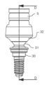
도 1은 Ti 베이스와 보철 나사를 갖는 전방향 다중 유닛 어버트먼트 조립체의 제1 실시예의 하단 분해 등각 투영도이다.
도 2는 Ti 베이스와 보철 나사를 갖는 전방향 다중 유닛 어버트먼트 조립체의 제1 실시예의 상단 분해 등각 투영도이다.
도 3은 보철 나사 없이 구성요소의 길이방향 축이 정렬된 도 1 및 도 2의 조립된 시스템의 측면도이다.
도 4는 길이방향 축을 통해 취한 도 3의 조립된 시스템의 측단면도이다.
도 5는 스위블 쉘과 Ti 베이스를 재배향한 후에 도 4의 조립체의 측면도이다.
도 6은 도 1 및 도 2의 전방향 다중 유닛 어버트먼트의 상단 등각 조립도이다.
도 7은 임플란트에 부착하는 동안 도 3 및 도 4의 조립체의 측단면도이다. 삽화 도 7a는 임플란트 구동 도구의 상대적 스케일링을 포함한다.
도 8은 도 5에서와 같이 스위블 쉘과 Ti 베이스를 재배향한 후에 도 3 및 도 4의 조립체의 측단면도로서 로킹 나사를 이용하여 배향을 고정하는 것을 보여준다. 삽화 도 8a는 로킹 나사 구동 도구의 상대적 스케일링을 포함한다.
도 9는 보철 나사를 이용하여 Ti 베이스를 고정한 후에 도 8의 조립체의 측단면도이다.
도 10은 선형 구성의 전방향 다중 유닛 어버트먼트와 Ti 베이스의 제2 실시예의 하단 조립 등각 투영도이다.
도 11은 도 10의 실시예의 측면도이다.
도 12는 길이방향 축을 따른 도 11의 실시예의 단면도이다.
도 13은 보철 나사가 추가된 후에 도 11의 실시예의 단면도이다.
도 14는 Ti 베이스와 보철 나사를 갖는 전방향 다중 유닛 어버트먼트의 제3 실시예의 상단 분해 등각 투영도이다.
도 15는 선형 조립 구성으로 도 14의 실시예의 상단 등각 투영도이다.
도 16은 길이방향 축을 따른 도 14의 실시예의 단면도이다.
도 17은 육각형 내부(Torx) 구동 피처를 갖는 도 14의 실시예에 대한 로킹 나사의 개략적인 상단 평면도이다.
도 18은 4-로브 내부 구동 피처를 갖는 도 14의 실시예에 대한 로킹 나사의 개략적인 상단 평면도이다.
도 19는 도 14의 실시예에 대한 로킹 나사와 어버트먼트 베이스를 갖는 4-로브 드라이버 팁의 상단 분해 등각 투영도이다.
도 20은 전방향 어버트먼트의 제4 실시예에 대한 슬리브와 스위블 장착부가 있는 2-부분 어버트먼트 베이스 스템의 상단 분해 등각 투영도이다.
도 21은 도 20의 슬리브와 스위블 장착부가 있는 조립된 2-부분 어버트먼트 베이스 스템의 상단 등각 투영도이다.
도 22는 길이방향 축을 따라 도 21의 슬리브와 스위블 장착부가 있는 조립된 2-부분 어버트먼트 베이스 스템의 단면도이다.
도 23은 보철물과 임플란트를 포함하는 전방향 다중 유닛 어버트먼트의 대표적인 실시예의 적용 환경의 단면도이다.1 is a bottom exploded isometric view of a first embodiment of an omnidirectional multi-unit abutment assembly with a Ti base and prosthetic screws.
Figure 2 is a top exploded isometric view of a first embodiment of an omnidirectional multi-unit abutment assembly with a Ti base and prosthetic screws.
Figure 3 is a side view of the assembled system of Figures 1 and 2 without prosthetic screws and with the longitudinal axes of the components aligned.
Figure 4 is a side cross-sectional view of the assembled system of Figure 3 taken through the longitudinal axis.
Figure 5 is a side view of the assembly of Figure 4 after reorienting the swivel shell and Ti base.
Figure 6 is a top isometric assembled view of the omni-directional multi-unit abutment of Figures 1 and 2;
Figure 7 is a cross-sectional side view of the assembly of Figures 3 and 4 while attached to an implant. Inset FIG. 7A includes relative scaling of the implant actuation tool.
Figure 8 is a side cross-sectional view of the assembly of Figures 3 and 4 after reorienting the swivel shell and Ti base as in Figure 5, showing fixing the orientation using a locking screw. Illustration 8A includes relative scaling of the locking screw drive tool.
Figure 9 is a cross-sectional side view of the assembly of Figure 8 after securing the Ti base using prosthetic screws.
Figure 10 is a bottom assembled isometric view of a second embodiment of an omnidirectional multi-unit abutment and Ti base in linear configuration.
Figure 11 is a side view of the embodiment of Figure 10.
Figure 12 is a cross-sectional view of the embodiment of Figure 11 along the longitudinal axis.
Figure 13 is a cross-sectional view of the embodiment of Figure 11 after prosthetic screws have been added.
Figure 14 is a top exploded isometric view of a third embodiment of an omnidirectional multi-unit abutment with a Ti base and prosthetic screws.
Figure 15 is a top isometric view of the embodiment of Figure 14 in a linear assembled configuration.
Figure 16 is a cross-sectional view of the embodiment of Figure 14 along the longitudinal axis.
Figure 17 is a schematic top plan view of a locking screw for the embodiment of Figure 14 with a hexagonal internal (Torx) drive feature.
Figure 18 is a schematic top plan view of a locking screw for the embodiment of Figure 14 with a four-lobe internal drive feature.
Figure 19 is a top exploded isometric view of a four-lobe driver tip with locking screw and abutment base for the embodiment of Figure 14.
Figure 20 is a top exploded isometric view of a two-part abutment base stem with sleeve and swivel mount for a fourth embodiment of an omnidirectional abutment.
Figure 21 is a top isometric view of the assembled two-part abutment base stem with sleeve and swivel mount of Figure 20;
Figure 22 is a cross-sectional view of the assembled two-part abutment base stem with the sleeve and swivel mount of Figure 21 along the longitudinal axis.
23 is a cross-sectional view of the application environment of a representative embodiment of an omnidirectional multi-unit abutment comprising a prosthesis and an implant.
나사 부착형 전방향 다중 유닛 어버트먼트의 이점을 제공하기 위한 옵션을 예시하기 위해 본 개시내용에 포함된 다수의 실시예가 있다. 도 1 및 도 2는 4개의 부분, 즉, 어버트먼트 베이스(1), 스위블 장착부(2), 스위블 베이스(3), 및 로킹 나사(4)를 포함하는 전방향 다중 유닛 어버트먼트(100)의 일 실시예의 분해도를 예시한다. 대표적인 Ti 베이스(5)와 보철 나사(6)는 또한 도 1과 도 2의 분해도에 도시되어 있다. 이러한 전방향 다중 유닛 어버트먼트 조립체(100)는 귀금속 및 비귀금속 및 합금, 세라믹, 및 고강도 가공 폴리머(예를 들어, PEEK, PEI), 또는 전술한 재료의 조합을 비롯하여 임플란트 어버트먼트 시스템을 위한 티타늄 또는 임의의 다른 적절한 재료로 제조될 수 있다. 원치 않는 생물학적 성장을 방지하거나 치유를 촉진하기 위해 표면 또는 부품 사이의 공간에 치료제, 코팅 또는 겔이 추가될 수 있다. 도 3은 보철 나사(6)가 선형 배향으로 있는 것을 제외하고 도 1 및 도 2의 요소를 도시한다. 도 4는 도 3의 길이방향 단면 지정자 A-A를 따라 도 3의 조립체의 내부 피처를 예시한다. Ti 베이스(5)의 존재는 도 4에 예시 목적으로 도시되어 있음에 유의한다. Ti 베이스(5)는 궁극적으로 보철물(도시되지 않음)에 유지되고 도 6에 도시된 바와 같이 보철 나사(6)를 사용하여 전방향 다중 유닛 어버트먼트에 부착된다. 보철 나사(6)는 영구 나사일 수 있거나 공동 소유된 미국 특허 제11,311,354호 및 연속성과 관련된 다른 출원에 설명된 유형의 임시 체결구일 수 있다. 도 6은 선형 구성의 도 1 및 도 2의 조립체의 사시도이다. 도 5는 약 30도로 틸트된 실시예의 측면도이다. 도 7 내지 도 9는 이 실시예를 임플란트에 설치하고 조절하는 여러 스테이지를 도시한다.There are a number of embodiments included in this disclosure to illustrate options for providing the benefits of a screw-attached omnidirectional multi-unit abutment. 1 and 2 show an omnidirectional
어버트먼트 베이스(1)는 근위 단부 상에 어버트먼트 베이스 구동 피처(10)와 함께 직경이 약 3.25 mm일 수 있는 볼 또는 구형 부분(13)을 포함한다. 예시된 바와 같이, 이 구동 피처는 볼 부분(13)의 상단에 있는 길이방향 축에 센터링된 T5 크기의 육각형 내부(Torx) 구동 피처 소켓일 수 있다. 다른 유형의 구동 도구가 사용될 수도 있다. 어버트먼트 베이스(1)의 원위 단부에는 환자의 턱 뼈에 고정되는 임플란트(16)의 암나사에 부착하기 위한 나사 부분(14)이 있다. 임플란트(16)와 하악골 또는 상악골에 대한 그 부착은 본 개시내용에서 개략적으로 설명되는데, 전방향 다중 유닛 어버트먼트의 독창적인 개념은 상이한 어버트먼트와 공유하도록 구성될 수 있기 때문이다. 암나사를 갖는 도 7에 예시된 일반 임플란트(16)는 매우 일반적인 설계이지만, 어버트먼트 베이스 부착부(14)와 안착부(21)는 다른 임플란트에 합치하도록 구성될 수 있다.The
스위블 베이스(3)는 구멍(19) 및 어버트먼트 베이스(1)의 볼 부분(13)의 곡률과 본질적으로 일치하도록 크기 설정되고 형상화된 내부 곡률 부분(15)을 포함한다. 예시된 스위블 장착부(2)는 로킹 나사(4)의 외부 나사부(9)에 부착하기 위한 내부 나사부(20)를 포함한다. 이는 또한 보철 나사를 이용하여 전방향 다중 유닛 어버트먼트(100)에 장착될 때 Ti 베이스(5)를 지지하고 배향시키기 위한 Ti 베이스 안착 피처(22)를 포함한다. 스위블 장착부는 조립을 돕기 위해 렌치와 같은 도구를 부착하거나 Ti 베이스(5)의 방위각 배향(예시되지 않음)을 제한하는 데 사용될 수 있는 맞물림 피처(11)를 임의로 포함할 수 있다. Ti 베이스와 임플란트 어버트먼트의 맞물림 피처를 일치시켜 Ti 베이스의 배향을 제한하는 것은 단일 치아 크라운에 유용한 일반적인 기술이다. 본 명세서의 전방향 다중 유닛 어버트먼트(100) 실시예는 상세히 설명하지 않을 정합 어버트먼트 장착 표면과 비원통형 대칭성 Ti 베이스의 방위각 배향을 고정함으로써 단일 치아 보철물에 쉽게 적용될 수 있다.The
어버트먼트 베이스(1)의 볼 부분(13)은 스위블 베이스 구멍(19)을 통해 연장되는 어버트먼트 베이스 나사의 나사 부분(14)과 함께 볼 부분(13) 둘레의 스위블 쉘을 포함하는 스위블 장착부(2)와 스위블 베이스(3) 사이에 포획될 수 있다. 이러한 삽입 프로세스를 위해, 구멍(19)은 어버트먼트 시트 돌출부(21)보다 커야 한다. 스위블 베이스(3)와 스위블 장착부(2)는 베이스 조립체(101)를 형성하기 위해 볼(13) 둘레에 위치 설정한 후에, 예를 들어 레이저를 이용한 연속 용접 또는 스폿 용접에 의해 계면 조인트(12)에 우선적으로 결합된다. 이러한 결합 기술은 더 짧은 거리에 걸쳐 더 얇은 쉘의 강력한 조립을 제공하지만, 쉘 내에 볼 부분(13)을 포획하기 위해 다른 결합 기술이 사용될 수도 있다. 도 4의 단면도에 도시된 바와 같이, 결합 후, 조립된 스위블 베이스(3)와 스위블 장착부(2)의 내부 곡률(15)과 구멍(19)의 기계적 설계는 어버트먼트 베이스의 볼 부분(13)이 스위블 쉘을 빠져나가는 것을 방지하도록 설계될 수 있다. 구멍(19)의 상대적인 크기 및 형상과 어버트먼트 시트 돌출부(21)에 있는 어버트먼트 베이스(1)의 크기 및 형상은 가능한 틸트 범위를 결정한다. 일반적으로, 스위블 베이스 구멍(19)과 스위블 장착부의 내부 나사부(20)의 작은 직경 또는 폭이 모두 볼(13)의 폭보다 더 작은 경우, 볼(13)은 로킹 나사(4) 없이 쉘 내에 포획된다.The
예시된 로킹 나사(4)는 스위블 장착부(2)의 내부 나사부(20)와 맞물리는 외부 나사부(9)를 갖는다. 예를 들어, 이들 나사부의 크기는 m3x0.35일 수 있다. 로킹 나사(4)는 또한 보철 나사(6)를 부착하기 위한 내부 나사부(7) 및 스위블 장착부(2)에 로킹 나사(4)를 조이기 위한 도구 부착용 내부 구동 피처(8)를 갖는다. 대표적인 보철 나사 크기는 m1.4x0.3 나사부, m1.6x0.35, UNF 1-72 등을 포함한다. 구동 피처(8)는 Torx T5 또는 T6, 0.035" 내지 0.050" 육각형 또는 정사각형 드라이버, 또는 유사한 크기의 직선형 및 스타형 드라이버를 비롯한 일반적인 치과용 드라이버를 수용하는 소켓일 수 있다. 예시된 바와 같이, 내부 나사부(7)와 구동 피처(8)는 로킹 나사의 길이방향 축을 따라 부분적으로 중첩된다. 이는 설계 선택이다. 완전한 축방향 중첩 또는 축방향 중첩 없음은 다른 설계 옵션이다.The illustrated locking screw (4) has an external thread (9) that engages with an internal thread (20) of the swivel mounting portion (2). For example, the size of these threads may be m3x0.35. The locking
스위블 베이스(3)는 로킹 나사(4)가 조여질 때 구형 볼 피처(13)의 세그먼트와 맞물리도록 구성된다. 도시된 도면과 단면은 도 5 및 도 8에 도시된 바와 같이 스위블 베이스와 장착부가 30도 원추 내 어느 위치에나 위치 설정 및 회전될 수 있는 실시예를 예시한다. 허용되는 틸트 크기와 조절 배향은 설계 선택이지만, 대부분의 임상 용례에는 일반적으로 30도 틸트이면 충분하다. 본 실시예에 도시된 바와 같이, 스위블 장착부(2)의 스위블 베이스 구멍(19)과 나사부가 있는 구멍(20)은 볼 부분(13)의 직경보다 작다. 이 경우, 어버트먼트 베이스(13)의 볼 부분은 스위블 베이스(3)와 스위블 장착부(2)가 상호 부착될 때 이들 2개의 부분에 의해 느슨하게 포획될 수 있다. 즉, 로킹 나사(4)는 예시된 실시예에서 볼 부분(13)을 포획하는 쉘을 갖기 위해 스위블 장착부(2)에 부착될 필요가 없다. 이는 설계 옵션이고, 본 개시내용의 독창적인 개념으로부터 이익을 획득하기 위한 요구 사항은 아니다.The
Ti 베이스(5)를 갖는 이러한 전방향 다중 유닛 어버트먼트 실시예의 도 4의 단면도는 요소 사이의 바람직한 기하학적 관계의 이점 중 일부를 예시하기 위해 사용될 수 있다. 도시된 바와 같이, 볼 부분(13)은 스위블 베이스(3), 스위블 장착부(2), 및 로킹 나사(4)에 의해 형성된 쉘의 운동 범위 전체에 걸쳐 구형이다. 구멍에 가까운 스위블 베이스(3)와 어버트먼트 시트(21) 근방의 어버트먼트 베이스(1) 표면(61)의 간섭으로 인한 틸트 범위 제한은 도 5와 도 9에서 각도(b)로 라벨 표시되어 있다. 스위블 장착부(2)의 내부 곡률은 볼 부분(13)의 내부 곡률과 본질적으로 동일하다. 로킹 나사(4)는 또한 접촉 영역에서 볼(13)과 본질적으로 동일한 곡률을 갖는다. 스위블 장착부(2)의 내부 곡률(15)은 볼(13)의 곡률보다 우선적으로 약간 더 크다. 결과적으로, 로킹 나사(4)가 조여지면, 볼 부분(13)은 스위블 베이스(3)의 내부 곡률(15) 및 로킹 나사(4)의 대응하는 내부 곡률과 접촉하게 된다. 스위블 장착부(2)의 내부 곡률이 더 크기 때문에, 로킹 나사(4)를 완전히 조였을 때 볼과 접촉되지 않는다. 이는 볼에 대한 스위블 베이스의 보다 일관되고 지속적인 원형 밀봉부를 제공하여 전방향 다중 유닛 어버트먼트 조립체 내부로 생물학적 오염이 유입되는 것을 차단하는 데 도움이 된다. 도 4의 선형 구성에서, 로킹 나사(4)는 또한 볼 부분(13)과 동등한 원형 밀봉부를 제공한다. 도 9의 최대 틸트 조건에 예시된 바와 같이, 볼에 대한 스위블 베이스(3)의 연속적인 밀봉부가 유지된다. 그러나, 볼(13)에 대한 로킹 나사(4)의 밀봉부는 어버트먼트 구동 피처(10)로 인해 연속적이지 않다. 그러나, Ti 베이스(5)와 보철 나사(6)가 전방향 다중 유닛 어버트먼트에 적용되면, 어버트먼트 구동 피처(10)는 효과적으로 밀봉된다.The cross-sectional view in Figure 4 of this omnidirectional multi-unit abutment embodiment with a
볼(13)에 대한 중공 로킹 나사(4)의 상대적으로 큰 링 접촉은 강성 세트 나사의 집중된 접촉보다 더 넓은 영역에 걸쳐 클램핑력을 분산시킨다. 볼(13)에 대한 스위블 베이스의 연장된 접촉 및 일치 곡률(15)은 부품이 티타늄으로 제조될 때 스위블 베이스(3) 또는 스위블 장착부(4)를 유지하지 않고도 로킹 나사(4)를 25 Ncm 초과하여 조일 수 있을 만큼 충분한 마찰력을 갖는 것으로 결정되었다. 상대적으로 큰 접촉 면적은 또한 집중 판매된 세트 나사에 비교하여 클램핑으로 인한 볼(13)의 왜곡을 최소화하여, 볼(13) 기하형상의 왜곡으로 인한 간섭 없이 틸트 또는 방위각의 재배치를 용이하게 한다. 로킹 나사(4)의 비교적 큰 외경은 또한 보철 나사(6)의 나사부 폭과 비슷한 구동 도구 크기로 로킹 나사(4)에 토크를 가하기 위한 기계적 강도를 위해 내부 나사부(7)와 외부 나사부(9) 사이에 충분한 벽 두께를 제공한다.The relatively large ring contact of the hollow locking screw (4) with respect to the ball (13) distributes the clamping force over a larger area than the concentrated contact of a rigid set screw. The extended contact and coincident curvature (15) of the swivel base with respect to the ball (13) allows the locking screw (4) to exceed 25 Ncm without retaining the swivel base (3) or the swivel mounting (4) when the part is made of titanium. It was determined that it had sufficient friction to tighten. The relatively large contact area also minimizes distortion of the
비교적 큰 로킹 나사(4)는 스위블 장착부의 내부 나사부(20)와 맞물린 외부 로킹 나사의 나사부(8)의 충분한 개수를 제공하여 볼(13)에 안정적인 클램핑력을 제공한다. 스위블 장착부(2)와 스위블 베이스(3) 사이의 조인트(12)에서 나사부(예시되지 않음)가 또한 사용될 수 있지만, 전방향 다중 유닛 어버트먼트 직경은 도 4에 도시된 상대적 크기와 동등한 강도를 갖도록 충분한 벽 두께 및 맞물린 나사부 깊이를 갖도록 증가되어야 한다. 그러나, 로킹 나사(4)의 과도한 토크를 방지하는 것이 바람직한 경우, 스위블 장착부(2)와 스위블 베이스(3) 사이의 나사부의 제한된 맞물림을 사용하여 임계 토크에 도달할 때 분리를 유발할 수 있다. 토크 제한을 위한 다른 옵션은 전술한 바람직한 용접 조인트 강도를 조정하는 것, 스위블 장착부의 구멍(19) 크기를 증가시키는 것, 및/또는 더 낮은 토크 저항을 갖는 구멍(19)에 근접한 스위블 베이스에 의도적으로 더 얇은 벽 섹션을 도입하는 것을 포함한다. 의도적인 설계 실패로 인해 전방향 다중 유닛 어버트먼트가 손실될 가능성이 있지만, 이는 향후 보철물 또는 임플란트 유지 실패를 초래할 수 있는 과도한 응력보다 바람직할 수 있다.The relatively large locking screw (4) provides a sufficient number of threaded portions (8) of the outer locking screw engaging with the inner threaded portion (20) of the swivel mounting portion to provide a stable clamping force to the ball (13). A threaded portion (not shown) may also be used in the joint 12 between the
도 4에 예시된 중공형 로킹 나사(4)와 구동 기하형상은 치과 시스템 설치 및 유지 보수에 이점을 제공한다. 스위블 베이스(3)를 스위블 장착부(2)에 부착하여 베이스 조립체(101)를 형성한 후, 스위블 장착부(2)와 스위블 베이스(3)에 의해 형성된 쉘 부분에 의해 임플란트 베이스의 볼 부분(13)이 포획된다. 로킹 나사(4)는 스위블 장착부(2) 내로 시작되어 이를 고정할 수 있을 만큼 충분히 회전될 수 있지만, 볼 부분(13)과 접촉하지 않고 전방향 다중 유닛 어버트먼트 조립체(100)를 형성할 수 있다. Ti 베이스(5)는 임의로 전방향 다중 유닛 어버트먼트 조립체의 상단에 배치될 수 있으며, 부품은 도 3 및 도 4에 도시된 바와 같이 공통 축을 따라 정렬될 수 있다. Ti 베이스(5)는 어버트먼트 베이스(1), 스위블 베이스(3), 스위블 장착부(2) 및 로킹 나사(4)를 설치하고 배향하는 동안 제자리에 있을 필요가 없다. 따라서, 정렬되면, 구동 도구(17)가 Ti 베이스(5)와 로킹 나사(4)를 통해 삽입되어 도 7에 예시된 바와 같이 어버트먼트 베이스(1)의 구동 피처(10)와 맞물릴 수 있다. 어버트먼트 베이스 구동 계면(10)과 맞물리기 위해 로킹 나사(4)를 통과한 후 구동 도구(17)를 약간 회전시키는 것이 필요할 수 있다는 점에 유의한다. 바람직하게는, 구동 도구(17)와 어버트먼트 베이스 구동 피처(10)의 맞물림 끼워맞춤은 도 7에 도시된 바와 같이 전방향 다중 유닛 어버트먼트(100)가 구동 도구(17) 상에 유지되게 하여 전방향 다중 유닛 어버트먼트 조립체를 임플란트(16)에 제공하기에 충분한 마찰을 갖는다. 권출 방향으로 로킹 나사(4)를 약간 조이면 이러한 유지에 도움이 될 수 있다. 구동 도구(17)가 회전됨에 따라, 어버트먼트 베이스 나사부(14)는 임플란트(16)와 맞물리고 전방향 다중 유닛 어버트먼트 조립체는 나사 결합되어 임플란트(16)에 대한 어버트먼트 시트(21)의 원하는 안착을 달성할 수 있다. 구동 도구가 어버트먼트 베이스(1) 및 로킹 나사(4)와 모두 맞물리므로, 이들 부품은 동시에 회전한다. 로킹 나사(4) 위치는 어버트먼트 베이스(1)에 대해 변하지 않기 때문에, 볼 부분(13)은 스위블 베이스(3)와 로킹 나사(4) 사이에 파지되지 않는다. 구동 도구(17)로부터의 회전력은 어버트먼트 베이스 나사부(14)를 임플란트(16) 내로 더 깊게 구동한다.The
임플란트와 접촉하는 어버트먼트 베이스의 안착 부분(21)은 고정 각도 어버트먼트의 안착 기하형상과 일치하도록 수정될 수 있다. 구동 피처(10)는 어버트먼트 베이스(1)의 나사 부분(14)을 임플란트(16)에 고정시키는 것이 가능하다. 어버트먼트 베이스(1)를 임플란트에 조이는 것은 어버트먼트 시트(21)에서 원하는 안착 압력이 획득될 때까지 진행될 수 있다. 대표적인 토크 값은 약 30 Ncm이지만, 그 값은 채용된 임플란트 시스템에 따라 다르며 이보다 더 높거나 더 낮을 수 있다. 보철물을 즉시 로딩하기 위해서는, 토크 값이 임플란트를 턱 뼈에 식립할 때 사용되는 토크 값보다 더 작아야 한다.The seating
도 8에 도시된 바와 같이, 일단 어버트먼트 베이스(1)가 임플란트(16)에 고정되면, 도 7의 선형 구성은 더 이상 필요하지 않다. 보철물 부착에 원하는 Ti 베이스(5)를 수용하기 위한 스위블 장착부(2)의 틸트 및 방위각은 로킹 나사(4)에 삽입되는 구동 도구(18)의 움직임에 의해 선택될 수 있다. 구동 도구(18)를 회전시키면 로킹 나사(4)와 스위블 베이스(3)가 볼 부분(13)을 클램핑하고 전방향 다중 유닛 어버트먼트(100)의 각도를 로킹시킨다. 로킹 나사(4)가 조여지는 동안 로킹 나사와 스위블 베이스가 회전하는 것을 방지하기 위해 맞물림 피처(11)가 포함될 수 있다. 작은 구멍이나 스플라인과 같은 다른 맞물림 피처도 이러한 목적을 위한 회전 방지 또는 방위각 선택 피처로서 사용될 수 있다. 단일 치아 보철물의 경우, Ti 베이스 상의 회전 고정 피처와 맞물리는 스위블 장착부(2) 상의 선택 피처가 로킹 나사(4)를 조이는 동안 Ti 베이스의 방위각을 선택하고 유지할 수 있다. 회전 방지 피처와 맞물리고 18과 유사한 구동 도구를 포함하는 동축 2피스 도구를 사용하여 스위블 장착부(2)와 로킹 나사(4)를 어버트먼트 베이스(1)의 볼 부분(13) 상의 제자리에 배향하고 조일 수 있다. 도 5의 배열에 포함된 Ti 베이스(5)를 갖는 것은 방위각 선택에 편리할 수 있다.As shown in Figure 8, once the
로킹 나사(4)의 구동 피처(7)는 바람직하게는 임시 및 최종 보철물 모두에서 Ti 베이스(5)를 통해 접근 가능하다. 이는 시간 경과에 따라 느슨해지면 로킹 나사(4)를 적절한 배향으로 이동시키고 다시 토크를 가할 수 있게 하며, 수동적 적합을 개선시키기 위해 약간의 조절을 하게 하고, 복수의 전방향 다중 유닛 어버트먼트(100) 내에서 하나의 전방향 다중 유닛 어버트먼트(100)를 교체하고 재정렬할 수 있게 한다. 삽화 도 7a에 도시된 구동 도구 치수(d1)와 삽화 도 8a에 도시된 구동 도구 치수(d2)의 비교로부터, 도 8에 도시된 구동 도구(18)는 도 7의 구동 도구(17)보다 크다. 이는 필수가 아니다. 예를 들어, 어버트먼트 베이스(1)를 구동하기 위한 T5 드라이버(17)와 로킹 나사(4)를 고정하기 위한 T6 드라이버(18)와 같은 2개의 상이한 크기를 사용하는 이점은 어버트먼트 베이스를 구동하는 동안 로킹 나사(4)에 추가 여유 공간을 제공한다. 어버트먼트 베이스(1)를 구동하는 데 사용되는 토크는 로킹 나사(4)에 사용되는 토크보다 더 높게 선택될 수 있기 때문에, 구동 도구(17)가 있는 제1 토크 렌치와 구동 도구(18)가 있는 제2 토크 렌치는 원하는 토크가 획득되는 것을 보장하는 도움이 될 수 있다. 물론, 조립된 전방향 다중 유닛 어버트먼트(100)가 도 7에 도시된 바와 같이 임플란트(16)에 설치되기 위해서는, 구동 도구(17)의 크기와 형상이 로킹 나사(4)를 통과해야 한다. 도 8의 구동 도구(18)는 도시된 로킹 나사 내부 구동 계면(8)이 로킹 나사(4)의 원위측까지 내내 연장되지 않기 때문에 로킹 나사(4)를 완전히 통과하는 것이 방지된다. 이는 설계 선택이다.The driving feature 7 of the locking
일부 의사는 미리 결정된 원하는 토크가 임플란트 베이스(1)와 로킹 나사(4)에 적용되는 시기를 결정하기 위해 교정된 객관적인 도구 대신에 근육 기억 경험을 사용하도록 선택할 수 있다. 어버트먼트 베이스 구동 계면(10)과 로킹 나사 구동 계면(8)이 동일한 크기와 형상이면, 구동 도구(17 및 18)에 하나의 도구를 사용할 수 있다. 이 경우, 도 7에서와 같이 임플란트(16) 내로 어버트먼트 베이스(1)를 구동한 후, 구동 도구(17)를 어버트먼트 베이스 구동 계면(10)과 맞물림 해제할 수 있을 정도로만 충분히 추출한 후 로킹 나사(4)를 회전시켜 전방향 다중 유닛 어버트먼트(100) 위치를 로킹하도록 재배치하면 된다. 상이한 교정 토크가 필요한 경우, 동일한 구동 도구 팁 크기에 2개의 상이한 렌치를 사용할 수 있다. 일부 의사는 토크 프로세스 단계 모두에서 구동 팁을 전방향 다중 유닛 어버트먼트에 삽입된 상태로 남겨두고 토크 렌치 설정을 상이한 값으로 전환하는 것을 선호할 수 있다. 구동 도구(17)의 회전축은 일반적으로 구동 도구(18)와 상이하기 때문에, 어버트먼트 베이스(1)와 로킹 나사(4)에 대해 동일한 토크 크기를 사용하는 것이 허용될 수 있다. 2개의 상이한 토크 설정 사이를 전환할 수 있는 푸시 버튼이나 기타 선택기를 갖는 토크 렌치가 유용할 수 있다. 자동 선택은, 예를 들어, 스프링 로딩식 외장이 더 높은 토크 메커니즘과 맞물리게 하도록 구동 도구 팁의 축을 따라 힘을 요구함으로써, 로킹 나사 구동 계면(8)에 비교하여 어버트먼트 베이스 구동 계면(10)과 맞물리는 데 필요한 더 깊은 구동 도구 깊이 사이의 차이에 기반할 수 있다. 이 경우, 더 낮은 토크 설정은 활주되기는 하지만 원한다면 맞물린 상태를 유지할 수 있다.Some surgeons may choose to use muscle memory experience instead of calibrated objective tools to determine when a predetermined desired torque should be applied to the implant base (1) and locking screw (4). If the abutment
도 9는 Ti 베이스(5)를 유지하는 보철 나사(6)를 포함하는 전방향 다중 유닛 어버트먼트 조립체(100)의 단면도를 도시한다. 보철 나사(6)는 참조된 미국 특허 제11,311,354호에 설명된 바와 같이 분리 가능한 체결구(도시되지 않음)로 교체되어 리프트 오프 프로세스로 Ti 베이스(5)를 보철물에 위치 설정하는 것을 용이하게 할 수 있다. Ti 베이스(5)가 보철물에 통합된 후에도, 보철 나사(6)를 제거함으로써 로킹 나사 구동 계면(8)에 접근할 수 있음에 유의한다. 이는 본질적으로 도 9에서 도 8로 구성을 변경하는 것이다. 이 이점은 다른 실시예가 제시된 후에 더 상세히 설명될 것이다.Figure 9 shows a cross-sectional view of an omnidirectional
도 1 내지 도 9에 도시된 실시예의 변형이 도 10 내지 도 13에 예시되어 있다. 실용적인 설계 관점에서, 종래의 어버트먼트 직경, 안착 높이(제1 실시예에서 Ti 베이스(5)의 안착 표면(22)과 임플란트 안착 표면(21) 사이의 거리) 및 기타 치수 제약이 주어지면, 전방향 다중 유닛 어버트먼트 설계는 또한 어버트먼트 베이스(30)와 볼 또는 구형 피처(31)가 초기에 별개의 구성요소인 실시예를 포함할 수도 있다. 도 1 내지 도 9의 실시예에서, 볼의 직경은 약 3 mm이다. 도면에는 약 2.5 mm의 공칭 안착 높이가 예시되어 있다.A variation of the embodiment shown in Figures 1-9 is illustrated in Figures 10-13. From a practical design perspective, given the conventional abutment diameter, seating height (distance between
도 10 내지 도 13에 예시된 제2 실시예는 도 1 내지 도 9에 도시된 전방향 다중 유닛 어버트먼트 조립체(100)와 동일한 임플란트(16) 및 Ti 베이스(5)로 작업하기 위해 거의 동일한 치수로 도시되어 있다. 어버트먼트 시트(42)와 Ti 베이스 시트(41) 사이의 안착 높이도 비슷하다. 주요 차이점은 스위블(32)이 2-부분 어버트먼트 베이스(30)의 부분 사이에 포획된다는 점이다. 도 12의 어버트먼트 베이스(30)는 스템 부분(34)에 부착된 별개의 볼 부분(31)을 포함한다. 예를 들어, 스위블 베이스가 간섭 없이 필요한 어버트먼트 직경을 통과하지 못하는 경우, 별개 장치(31)가 유용할 수 있다. 결과적으로, 도 10 내지 도 13의 실시예는 어버트먼트 베이스 스템 부분(34)의 정합 포스트 피처(35)에 부착되는 원위 장착 구멍(46)이 있는 구동 계면(45)을 갖는 볼(31)을 포함한다. 볼(31)을 스위블(32)에 삽입한 후, 볼(31)은 압입, 열 수축, 레이저 용접, 접착제, 또는 그 조합과 같은 기계적 맞물림의 임의의 형태에 의해 베이스 스템 부분(34)에 조립된다. 예를 들어, 볼(31)은 포스트(34) 상에 가볍게 압입되어 계면(35)에 작은 반경방향 레이저 용접이 있을 수 있다. 이 방법은, 기계적 정밀도를 최소화하고 정합 조인트(35)에 필렛을 제공하며 이 조인트를 액체 유입으로부터 밀봉하면서, 볼을 베이스에 신뢰성 있게 결합한다.The second embodiment illustrated in FIGS. 10-13 uses nearly identical tools for working with the
예시된 실시예에서, 스위블(32)의 내부 나사부(38)의 작은 직경은 볼(31)이 스위블 장착부(32)의 내부 나사부(40)를 통해 삽입될 수 있을 만큼 충분히 크다. 구동 계면(45)은 조립을 위해 볼을 배향시키는 데 사용될 수 있다. 스위블(32)을 포획하고 로킹 나사(33)를 설치하여 조인 후, 볼(31)은 안착 표면(47)을 따라 스위블(32)과 접촉한다. 약 17.5도의 안착/간섭 표면이 도 12 및 도 13에 예시되어 있다. 로킹 나사(33)는 또한 계면(48)을 따라 볼(31)과 접촉한다. 표면 텍스처, 리지 또는 리브와 같은 볼(31)에 대한 정합 표면(48 및 47)의 로킹 능력을 향상시키기 위해 다양한 표면 마감 및 기계적 피처가 채용될 수 있다. 스위블(32)을 볼에 포획하는 이러한 접근법은 스위블(32)이 볼(31)에서 떨어지는 것을 방지한다는 점에 유의한다. 스위블(32)은 도 1 내지 도 9의 제1 실시예의 스위블 베이스(3)와 유사하게 볼의 원위 표면에 접촉하지만, 또한 스위블 장착부(2)의 이전 Ti 베이스 시트(22)에 의해 제공되는 것과 유사한 공지된 배향으로 Ti 베이스(5)를 지지하기 위한 Ti 베이스 시트(41)를 제공한다.In the illustrated embodiment, the small diameter of the internal thread 38 of the
로킹 나사(33)는 제1 실시예의 로킹 나사(4)와 유사하다. 로킹 나사는 보철 나사부(36), 구동 소켓 피처(37), 안착 표면(48) 및 외부 나사부(39)를 포함한다. 볼 부분(31)의 근위 단부는 전술한 로킹 나사(4)와 유사하게 로킹 나사(33)를 통해 접근될 수 있는 구동 소켓 피처(45)를 포함한다. 로킹 나사(33)가 구동 피처(37)를 사용하여 조여지면, 스위블(32)은 볼(31)의 안착 표면(47)과 맞물려 로킹 나사(33)가 스위블(32)을 임플란트 축에서 최대 30도 떨어진 이상적인 전방향 배향으로 그리고 원하는 방위각으로 고정할 수 있다. 다시 말해서, Ti 베이스(5)는 전방향 다중 유닛 어버트먼트의 설치 및 배향 설정 중에 존재할 필요가 없다. 보철 나사부(36)와 구동 피처(45, 37, 44)의 크기를 적절히 선택하면, 어버트먼트 베이스(30)를 임플란트(도시되지 않음)에 조이고, 로킹 나사(33)로 스위블(32)의 배향을 로킹하며, 보철 나사(44)를 조이는 세 단계에 단일 구동 도구를 이용할 수 있다. 예를 들어, 나사부(36)를 갖는 M1.6 x 0.35 보철 나사(43)의 통상적인 단일 T5 구동 도구는 구동 계면(37, 44 및 45)이 또한 T5 소켓 특성을 갖는 경우 사용될 수 있다. 물론, 이 경우, 로킹 나사 구동 계면(37)은 어버트먼트 베이스 구동 소켓 피처(45)와 맞물리기 위해 로킹 나사(33)(도시되지 않음)를 통해 연장되어야 한다. T5 드라이버용으로 제거된 M1.6 보철 나사부 부분은 보철 나사를 적절하게 유지하기 위해 적절한 나사부 무결성을 제공하도록 결정되었다. 다른 표준 및 맞춤형 나사부와 구동 기하형상 조합을 사용하여 단일 구동 도구를 사용할 수도 있다.The locking
볼(31)을 어버트먼트 베이스(30)에 조립함으로써, 임플란트 안착 위치(42)에서의 어버트먼트 베이스(30)의 폭은 제1 실시예보다 더 커질 수 있다. 제1 실시예에서, 어버트먼트 베이스(1)의 나사부 단부(14)는 스위블 베이스 구멍(19)에 삽입되어 볼 부분(13)과 접촉하였다. 스위블 장착부(2)를 스위블 베이스(3)에 결합하여 볼 부분(13)을 포획하였다. 본 실시예에서 스위블 베이스(3)와 스위블 장착부(2)의 특성을 일체형 스위블(32)로 병합함으로써, 어버트먼트 베이스의 원위 단부의 크기는 스위블(32) 구멍의 원위 단부에 있는 구멍에 의해 구속되지 않는다. 도 10 내지 도 13의 실시예에서, 볼이 스위블(32)을 통해 삽입되어 어버트먼트 베이스(30)에 결합되게 하도록 로킹 나사 외부 나사부(39)의 작은 직경은 볼(31)의 직경보다 커야 한다. 도 12와 도 4를 비교하면 스위블(32)과 로킹 나사(33) 사이의 나사부 맞물림 깊이가 더 짧다는 것을 알 수 있다.By assembling the
볼 피처가 있는 어버트먼트 베이스에 스위블 쉘 구성요소를 포획하기 위한 또 다른 접근법이 도 14 내지 도 16에 도시되어 있다. 이 실시예에서, 어버트먼트 베이스 조립체(101)는 스위블(32)과, 근위 단부에 구동 피처(45)가 있는 볼 피처(13)와 원위 단부에 테이퍼진 스템(51)을 갖는 테이퍼 스템(50)을 갖는 볼로 제조된다. 테이퍼진 스템(51)은 근위 단부에 테이퍼진 소켓(53)과 원위 단부에 어버트먼트 베이스 나사부(14)를 갖는 베이스(52)에 결합된다. 테이퍼 스템(50)이 있는 볼의 가장 넓은 부분은 볼(13)의 직경이다. 스위블(32)은 테이퍼진 스템(51)을 테이퍼진 소켓(53)에 삽입하기 전에 스위블(32)의 근위측에 테이퍼진 스템(51)을 삽입함으로써 포획된다.Another approach for capturing a swivel shell component in an abutment base with ball features is shown in Figures 14-16. In this embodiment, the
도 15 및 도 16은 어버트먼트 베이스 조립체(101)를 도시한다. 이전과 같이, 테이퍼진 스템(51)과 베이스(52)는 상이한 기술로 결합될 수 있다. 그러나, 계면(63)에 용접을 포함하는 것이 바람직하다. 도 16과 도 14를 비교하면 테이퍼진 스템(50)을 갖는 볼의 볼 부분(13)이 어버트먼트 베이스 볼(31)에 비교하여 개선된 구조적 안정성을 가질 수 있음을 알 수 있다. 이는 부품의 작은 크기와 원활한 회전 동작 및 제자리에 로킹되었을 때 부품의 타이트한 밀봉을 가지려는 요구를 고려할 때 중요할 수 있다.15 and 16 show the
도 14에 예시된 로킹 나사(49)는 근위 단부 근방의 외부 표면에 육각형 구동 피처(64)를 포함하는 것에 의해 이전 실시예의 로킹 나사(4 및 33)와 상이하다. 이 육각형 구동 피처(64)는 실패한 설치를 제거하는 데 도움이 되도록 제공된다. 예를 들어, 로킹 나사(4)에서 보철 나사 스템(25)이 부러지면, 로킹 나사 구동 계면(8)이 막혀 전방향 다중 유닛 어버트먼트 설치에 사용되는 구동 도구(18)가 삽입되지 않을 수 있다. 부러진 스템(25)을 제거하는 대신에, 렌치(도시되지 않음)를 육각형 피처(64)에 적용하여 로킹 나사(49)를 제거할 수 있다. 물론, 이러한 육각형 피처(64)는 일반적으로 Ti 베이스(5)가 전방향 다중 유닛 어버트먼트 상의 제자리에 있는 상태에서는 접근이 불가능하다. 결과적으로, 로킹 나사 구동 계면(37)은 수동적 적합을 개선하기 위해 전방향 다중 유닛 어버트먼트 배향을 정렬하고 로킹하는 데 도움이 되도록 보철물에 매립된 Ti 베이스를 사용하는 데 바람직하다. 필요한 경우, 막힌 로킹 너트(49)를 제거하는 데 도움이 되도록 스위블(32) 측면의 플랫(11)에 렌치를 적용할 수도 있는데, Ti 베이스(5)가 이를 덮지 않기 때문이다.The locking
도 17은 로킹 나사(49)의 평면도이다. 외부 에지에는 로킹 나사 외부 나사부(39)가 있고 중앙에는 Torx 스타일로서 도시된 로킹 나사 내부 구동 계면(8)이 있다. 로킹 나사 내부 나사부(7)의 대직경(66)(점선)과 소직경(65) 원호가 도시되어 있다. 소직경(65)은 연속적인 원이 아니라 로킹 나사 내부 나사부(7)와 축방향으로 중첩하는 로킹 나사 내부 구동 계면(8)으로 인해 일련의 불연속적인 원호 세그먼트이다. 로킹 나사(49)에는 로킹 나사 내부 구동 계면(8)과 로킹 나사(49)를 통해 내내 연장되는 내부 나사부(7)가 있다는 점에 유의한다. 달리 말하면, 충분히 긴 보철 나사부(25)와 구동 도구(18)가 모두 로킹 나사(49)의 두께를 통과할 수 있도록 로킹 나사(49)의 두께를 통해 이들의 축방향 중첩이 본질적으로 완전히 이루어진다. 구동 도구(18)가 전방향 다중 유닛 어버트먼트(100)의 배향을 로킹하기 위해 토크를 가하는 데 이용 가능한 로킹 나사(49)의 재료량은 내부 나사부(7)의 대직경(66) 및 소직경(65)에 의해 접경된 체적에서 구동 도구(18)에 로킹 나사 구동 계면(8) 소켓을 제공하기 위해 제거된 재료를 뺀 값에 대응한다(예시되지 않음). 구동 도구 계면(8)의 크기와 형상을 수정하여 보철 나사(6)를 유지하기 위한 나머지 내부 나사부(7)의 강도를 변경하고 내부 나사부(7)를 손상시키기 전에 배향을 고정하기 위해 로킹 나사(49)에 대한 최대 토크 적용을 변경할 수 있다.Figure 17 is a top view of the locking
도 18은 대안적인 로킹 나사 내부 구동 계면(54)을 갖는 로킹 나사(49)의 평면도이다. 이 구동 도구 계면(49)은 이미 예시된 Torx 구동 도구 계면의 6-로브 대신에 4-로브를 갖는다. 더 적은 수의 로브와 더 두드러진 로브 천이의 결과로서, 도 17과의 시각적 비교는 도 17에 비교하여 더 많은 내부 나사부가 유지된다는 것을 보여주기에 충분하다. 결과적으로, 내부 나사부(7)와 로킹 나사 구동 계면(54)의 축방향 중첩에 기인한 임의의 기계적 강도 저하를 보상하기 위해 이용 가능한 재료 및 기하학적 절충 옵션이 있어, 보철물이 제자리에 있는 상태에서 전방향 다중 유닛 어버트먼트(100)의 최종 정렬 및 로킹이 수행될 수 있다.18 is a top view of the locking
도 19는 도 18의 로킹 나사(49)를 갖는 4-로브 구동 팁(62) 및 일치하는 4-로브 구동 계면(60)을 갖는 어버트먼트 베이스(59)를 예시한다. 전방향 다중 유닛 어버트먼트(100)의 다른 부분은 명확성을 위해 도시되지 않는다. 구동 팁(62)은 로킹 나사(49)를 통과하도록 크기 설정되므로, 어버트먼트 베이스(59)를 임플란트(16)(도시되지 않음) 안으로 구동하는 데 사용될 수 있다. 구동 팁은 Ti 베이스 구멍(23)을 통과하도록 크기 설정되므로, 로킹 나사(49)를 회전시켜 Ti 베이스(5)가 매립된 보철물(도시되지 않음)을 통해 전방향 다중 유닛 어버트먼트의 위치를 고정할 수도 있다.Figure 19 illustrates an
도 20은 스위블(32)을 포획하기 위해 조립되는 2-부분 어버트먼트 베이스(55)의 또 다른 실시예를 예시한다. 이 실시예에서, 볼 부분(13)과 어버트먼트 베이스 나사부(14)는 어버트먼트 베이스 스템(56)에 포함된다. 어버트먼트 볼 베이스 스템의 원위 단부는 스위블(32)에 삽입된 다음 사용될 어버트먼트(16)의 계면 요구 사항과 일치하는 중공 슬리브(57)에 삽입된다. 슬리브(57)는 볼 부분(13)의 직경보다 큰 최대 폭을 갖는다. 결과적으로, 슬리브(57)가 어버트먼트 베이스 스템(56)에 결합될 때, 스위블(32)이 포획된다. 전술한 다양한 결합 작업 중 임의의 작업을 사용할 수 있지만, 도 22에 도시된 바와 같이 계면(58)에서의 용접을 포함하는 것이 바람직하다. 또한, 도 22에는 위의 조립 프로세스에 대한 2개의 중요한 치수가 도시되어 있다. 스위블(32)의 관통 구멍의 최소 직경 "d"는 볼 부분 아래에 있는 어버트먼트 베이스 스템(56)의 최대 폭 "c" 보다 커야 한다. 이전 실시예와 본 실시예의 유사성으로 인해, 다른 부분 및 특성은 설명되지 않는다.20 illustrates another embodiment of a two-
볼 상의 다양한 형태의 수형 핀, 어버트먼트 베이스 상의 암형 소켓, 볼 또는 어버트먼트의 나사형 포스트와 같이 어버트먼트 연결 조립체가 부착된 볼에 스위블을 포획하는 다른 많은 방법이 가능하다. 독창적인 개념을 입증하고 최대의 배향 가요성을 제공하기 위해 본질적으로 구형인 볼이 예시되었지만, 배향을 의도적으로 제한하기 위해 다른 형상이 사용될 수도 있다. 정합 계면은 예시된 독창적인 개념 중 하나 이상을 계속 사용하는 아직 제시되지 않은 실시예의 목적을 충족하도록 맞춤화될 수 있다.Many other ways of capturing the swivel in the ball to which the abutment connection assembly is attached are possible, such as various types of male pins on the ball, female sockets on the abutment base, threaded posts on the ball or abutment. An essentially spherical ball is illustrated to demonstrate the original concept and provide maximum orientation flexibility, but other geometries may be used to intentionally limit orientation. The mating interface may be tailored to meet the purposes of yet-to-be-presented embodiments that still use one or more of the ingenious concepts illustrated.
도 23은 제1 실시예의 설치된 전방향 다중 유닛 어버트먼트(100)의 적용 환경의 단면을 도시한다. 임플란트(16)는 개략적으로 70으로 도시된 환자의 뼈와 연조직에 설치되었다. 어버트먼트 베이스(1)는 원하는 토크 레벨로 임플란트(16)에 나사 결합되었다. 이 경우, 스위블 장착부(4)는 본질적으로 도 8과 비슷한 최대 능력까지 틸트되었다. Ti 베이스(5)는 보철물(68)에 매립된다. 보철물의 교합 표면(72)은 개략적으로 72로 도시되어 있다. Ti 베이스(5)는 스위블 장착부(4) 상에 안착되지만, 보철 나사 접근 구멍(69)을 통해 로킹 나사 계면(8)이 구동 도구(71)에 접근할 수 있게 하도록 보철 나사(6)가 제거되었다. 4-로브 구동 도구(71)가 예시되어 있지만, 제1 실시예에 대해 전술한 바와 같이 어버트먼트 베이스(1)를 임플란트(16) 내로 구동하려면 더 작은 구동 도구(도시되지 않음)가 요구된다는 점에 유의한다. 제1 실시예에서 언급한 바와 같이, 보철물이 제자리에 있는 동안 전방향 다중 유닛 어버트먼트 배향을 변경할 수 있는 것이 유리할 수 있다. 이를 보다 상세히 설명하기 위해 도 23이 사용된다.Figure 23 shows a cross-section of the application environment of the installed omnidirectional
도 23에는 하나의 임플란트만 도시되어 있지만, 보철물이 여러 임플란트에 정합하는 여러 Ti 베이스를 포함하는 경우 현장 조절의 이점이 확대된다. 임플란트 장착을 위한 보철물의 제조나 수정 동안, Ti 베이스 위치의 불확실성이 누적될 수 있다. 이러한 시프트의 무작위 특성으로 인해, Ti 베이스의 배향과 위치는 서로로부터 그리고 처음에 보철물과 함께 Ti 베이스를 배향하는 데 사용된 어버트먼트 세트의 위치로부터 이동할 수 있다. Ti 베이스가 처음에는 완벽하게 위치 설정되었더라도, 시간 경과에 따라 환자의 턱 형상이나 보철물의 형상이 변경될 수 있다. 도 23에 도시된 바와 같이, 보철 나사(6)를 제거하면 구동 도구(71)로 로킹 나사(4)에 접근하여 풀 수 있다. 교합면(72)으로부터 보철물(68)에 재안착 힘을 인가하면 매립된 Ti 베이스(5)를 Ti 베이스 시트(22)에 대해 푸시하여 전방향 다중 유닛 어버트먼트의 배향을 전향시키게 된다. 보철물(68)에 재안착력을 유지하면서 구동 도구(71)로 로킹 나사(4)를 조이면 이 배향이 로킹된다. 그 후, 보철 나사(6)를 다시 삽입하고 토크를 가하여 Ti 베이스(5)와 보철물(68)을 제자리에 고정할 수 있다. 시간 경과에 따라 느슨해졌는 지를 확인하기 위해 로킹 나사(4)의 토크를 체크하는 것이 바람직한 경우, 보철물(68)에 매립된 Ti 베이스(5)를 통해 이를 수행할 수도 있다.Although only one implant is shown in Figure 23, the benefits of field control are magnified if the prosthesis includes multiple Ti bases mating to multiple implants. During manufacturing or modification of a prosthesis for implant placement, uncertainty in the Ti base position may accumulate. Due to the random nature of this shift, the orientation and position of the Ti bases can shift from each other and from the position of the abutment set that was initially used to orient the Ti base with the prosthesis. Even if the Ti base is initially positioned perfectly, the shape of the patient's jaw or the shape of the prosthesis may change over time. As shown in Figure 23, when the
유사하게, 세트의 하나의 전방향 다중 유닛 어버트먼트(100)가 고장나고 교체해야 하는 경우, 모든 보철 나사(6)를 제거한 후 매립된 Ti 베이스(5)가 있는 보철물(68)을 제거할 수 있다. 도 8 및 도 7에 도시된 각도 설정 및 임플란트 부착 프로세스를 반대로 하면 실패한 전방향 다중 유닛 어버트먼트 조립체(100)가 제거된다. 새로운 전방향 다중 유닛 어버트먼트(100)를 임플란트(16)에 부착하기 위해 도 7의 프로세스를 반복하면 어버트먼트 베이스(1)가 임플란트(16)에 고정되지만, 스위블 베이스(3), 스위블 장착부(2) 및 로킹 나사(4)로 구성된 쉘이 느슨해진다. 로킹 나사(4)에 최소한의 압력을 가하면 전방향 다중 유닛 어버트먼트의 배향을 유지하는 데 충분하므로 중력으로 인해 움직이지 않고 배향을 변경하는 데 최소한의 힘만 인가하면 된다. 보철물(68)에 Ti 베이스(5)를 맞물리기에 충분한 스위블 장착부(4)를 대략적으로 위치 설정하고 교합면(72)으로부터 보철물에 수동으로 압력을 가하면 새로 설치된 전방향 다중 유닛 어버트먼트를 재배향시켜 보철물에 이미 설치된 Ti 베이스(5)와 정렬된다. 로킹 나사(4)는 도 23에 도시된 바와 같이 적절한 위치에서 Ti 베이스(5)의 구멍(23)을 통해 조여질 수 있다. 로킹 나사(6)를 조이기 전에 새로 설치된 전방향 다중 유닛 어버트먼트(100)의 정렬 압력을 유지하기 위해 원래의 전방향 다중 유닛 어버트먼트(100)의 보철 나사(6)를 사용할 지의 여부는 임의적이다.Similarly, if one omnidirectional multi-unit abutment (100) of the set fails and needs to be replaced, the prosthesis (68) with embedded Ti base (5) can be removed after removing all prosthetic screws (6). You can. Reversing the angle setting and implant attachment process shown in FIGS. 8 and 7 eliminates the failed omnidirectional
로킹 나사 구동 계면(8)은 Ti 베이스(5)와 보철물(68)을 통해 접근 가능하기 때문에, 단일 나사 수동적 적합 테스트 프로토콜의 변형을 사용하여 원래 설치 시에 수동적 적합을 개선하기 위해 전방향 다중 유닛 어버트먼트의 배향을 약간 조절할 수 있다. 보철물(68)에 설치된 Ti 베이스(5)의 구멍(23)을 통해 전방향 다중 유닛 어버트먼트(100)를 재배향시키는 능력을 활용하기 위한 다양한 옵션이 있다. 한 가지 접근법에서는, 모든 보철 나사(6)가 제거된다. 보철물(68)이 제자리에 유지되는 동안, 모든 전방향 다중 유닛 어버트먼트 로킹 나사(4)를 느슨하게 한 다음 손으로 조여 약간의 마찰 저항을 제공하지만 회전 미끄러짐을 방지하지는 않는다. 적절하게 손으로 조이기 위한 실제 토크 값은 전방향 다중 유닛 어버트먼트의 구성과 표면 마감에 따라 다르지만, 일반적으로 수 Ncm 미만이다. 다음으로, 모든 보철 나사(6)를 다시 설치하고 권장 값으로 토크를 가한다. 이러한 방식으로, 전방향 다중 유닛 어버트먼트 각각의 배향은 보철물(68)에 더욱 밀접하게 일치될 것이다. 다음으로, 해당 위치에서 전방향 다중 유닛 어버트먼트의 로킹 나사(4)에 대한 접근을 제공하기 위해 단일 보철 나사(6)가 제거된다. 로킹 나사(4)는 미리 결정된 값으로 토크를 가한다. 보철 나사(6)를 다시 삽입하고 미리 결정된 값으로 토크를 가한다. 이는 전방향 다중 유닛 어버트먼트 로킹 나사(4)가 모두 조여지고 모든 보철 나사(6)가 조여질 때까지 반복된다.Since the locking screw drive interface (8) is accessible through the Ti base (5) and prosthesis (68), a modification of the single-screw passive fit test protocol was used to improve passive fit in the original installation by using an omnidirectional multi-unit The orientation of the abutment can be slightly adjusted. There are various options for exploiting the ability to reorient the omnidirectional
위의 미세 조절 프로세스는 초기 수동적 적합 레벨의 세부 사항에 따라 수정될 수 있다. 예를 들어, 전방향 다중 유닛 어버트먼트 로킹 나사(4) 중 일부만 풀고 나머지는 원래 보철물 피팅의 앵커 지점으로서 고정된 상태로 남겨두는 것이 바람직할 수 있다. 이는 더 나은 폐색이나 다른 이유에 대해 수동적 적합을 다소 타협해야 하는 요구 사항으로 인해 발생할 수 있다. 또는 전통적인 단일 나사 또는 나사 저항 테스트의 결과는 전방향 다중 유닛 어버트먼트의 하위 세트에 대한 배향 조절만 제안하거나 상이한 조절 순서를 제안할 수도 있다. 임의의 경우에, 이들 수동적 적합 개선은 보철물이 제자리에 있는 동안 전방향 다중 유닛 어버트먼트를 배향시키고 고정하는 능력을 직접적으로 따른다.The above fine-tuning process can be modified depending on the details of the initial passive fit level. For example, it may be desirable to loosen only some of the omnidirectional multi-unit abutment locking screws 4 and leave the rest fixed as anchor points for the original prosthesis fitting. This may be due to the requirement to compromise passive fit somewhat for better occlusion or other reasons. Alternatively, the results of a traditional single screw or screw resistance test may suggest only orientation adjustments for a subset of omnidirectional multi-unit abutments, or may suggest a different adjustment sequence. In any case, these passive fit improvements are directly dependent on the ability to orient and secure the omnidirectional multi-unit abutment while the prosthesis is in place.
위의 전방향 다중 유닛 어버트먼트(100) 실시예는 이미 인증을 받고 상업적으로 성공한 Ti 베이스(5) 및 나사형 임플란트(16)와 호환되도록 구성되는 것이 바람직하다. 널리 이용 가능한 임플란트에 대한 나사부 및 안착은 동일한 임플란트가 동일한 환자에서 위의 실시예 뿐만 아니라 종래의 직선형 어버트먼트와 함께 사용될 수 있기 때문에 재고 등식을 개선한다. 덜 중요하지만, 널리 이용 가능한 나사 부착형 Ti 베이스(5)와의 호환성도 이점으로서 확인되지만, 설명된 실시예의 독창적인 피처는 전술한 수동적 적합 개선 또는 설치 효율 및 수리를 위한 독창적인 개념을 채택하는 새로 설계된 임플란트와 함께 작업하도록 통합되거나 적응될 수 있다. 이러한 독창적인 개념은 나사로 부착되지 않은 보철물과 함께 작업하도록 적응될 수도 있다. 이들 적응은 배제되지 않으며 본 명세서에 개시된 것으로 고려되며 이에 적용되도록 광범위하게 해석될 수 있는 청구범위 내에 있다. 미국 특허 제11,311,354호는 리프트 오프 프로세스에서 임시 체결구를 사용하여 보철물에 통합하기 위한 어버트먼트와 Ti 베이스를 정렬하는 다양한 접근법을 포함한다. 공동 소유 특허에 예시된 임시 체결구의 기본 설계는 전술한 전방향 다중 유닛 어버트먼트 및 Ti 베이스와 함께 채용될 수 있다.The above omnidirectional
다양한 실시예는 개시된 독창적인 개념을 예시하기 위해 설명되었으며, 본 발명을 제한하도록 의도되지 않는다. 독창적인 개념을 사용하여 추가 실시예를 생성하기 위해 치과 과학에서 알려진 재료, 구성요소 및 기술과 하나 이상의 실시예의 독창적인 요소를 조합하는 것은 본 개시내용의 일부인 것으로 고려된다.The various embodiments have been described to illustrate the inventive concepts disclosed and are not intended to limit the invention. Combining inventive elements of one or more embodiments with materials, components, and techniques known in dental science to create additional embodiments using inventive concepts is considered part of the present disclosure.
Claims (20)
길이방향 축을 갖는 어버트먼트 베이스로서, 어버트먼트 베이스는,
볼 부분과 어버트먼트 베이스 구동 계면을 포함하는 근위 단부; 및
임플란트에 부착하기 위한 나사부를 포함하는 원위 단부를 포함하는, 어버트먼트 베이스; 및
내부 표면과 외부 표면을 갖는 스위블 쉘로서, 원위 단부에 근접한 스위블 구멍과 근위 단부에 있는 나사형 구멍을 포함하는, 스위블 쉘; 및
길이방향 축을 갖는 로킹 나사를 포함하고, 로킹 나사는,
스위블 쉘의 나사형 구멍과 양립 가능한 외부 나사부를 갖는 부분; 및
보철 나사 샤프트와 맞물리도록 크기 설정된 내부 나사부를 갖는 부분; 및
로킹 나사 구동 계면을 포함하고;
로킹 나사를 회전시키면 로킹 나사의 길이방향 축의 배향을 어버트먼트 베이스의 길이방향 축에 평행하지 않은 배향으로 고정시킬 수 있는, 시스템.A system for aligning and attaching a dental prosthesis to an implant using a prosthetic screw, where the prosthetic screw includes a head and a threaded shaft, and the system includes:
An abutment base having a longitudinal axis, the abutment base comprising:
a proximal end comprising the buccal portion and the abutment base driving interface; and
an abutment base comprising a distal end including a threaded portion for attachment to an implant; and
a swivel shell having an interior surface and an exterior surface, the swivel shell comprising a swivel hole proximate a distal end and a threaded hole at a proximal end; and
a locking screw having a longitudinal axis, the locking screw comprising:
a portion having an external thread compatible with the threaded hole of the swivel shell; and
a portion having an internally threaded portion sized to engage a prosthetic screw shaft; and
comprising a locking screw drive interface;
A system in which rotating the locking screw can fix the orientation of the longitudinal axis of the locking screw to an orientation that is not parallel to the longitudinal axis of the abutment base.
스위블 구멍을 통해 연장되는 어버트먼트 베이스 나사부를 이용하여 볼 부분이 스위블 쉘 내부에 느슨하게 구속된 상태에서 어버트먼트 베이스 둘레의 스위블 쉘에 로킹 나사를 부착하여 다중 유닛 어버트먼트 조립체를 형성하는 단계;
로킹 나사를 통해 어버트먼트 구동 도구 팁을 삽입하여 어버트먼트 베이스 구동 계면과 맞물리게 하는 단계;
어버트먼트 베이스 구동 도구와 다중 유닛 어버트먼트 조립체를 임플란트에 제공하는 단계;
어버트먼트 베이스를 임플란트에 부착하기 위해 어버트먼트 베이스 구동 도구를 제1 토크로 회전시키는 단계;
어버트먼트 베이스 구동 계면으로부터 어버트먼트 베이스 구동 도구를 맞물림 해제하는 단계;
스위블 쉘을 상이한 배향으로 이동시키는 단계;
임플란트 축에 대한 스위블 쉘 축의 배향을 고정하기 위해 로킹 나사 구동 도구를 제2 토크로 회전시키는 단계;
Ti 베이스를 포함하는 보철물을 임플란트 어버트먼트 시스템에 제공하는 단계; 및
보철 나사를 이용하여 임플란트 어버트먼트에 보철물을 부착하는 단계를 포함하는, 방법.A method of aligning and attaching a dental prosthesis to an implant with prosthetic screws using the system of claim 1,
Forming a multi-unit abutment assembly by attaching a locking screw to the swivel shell around the abutment base with the ball portion loosely restrained inside the swivel shell using the abutment base thread extending through the swivel hole. ;
Inserting the abutment drive tool tip through the locking screw to engage the abutment base drive interface;
Providing an abutment base drive tool and a multi-unit abutment assembly to the implant;
rotating the abutment base drive tool with a first torque to attach the abutment base to the implant;
disengaging the abutment base drive tool from the abutment base drive interface;
moving the swivel shell to different orientations;
rotating the locking screw drive tool with a second torque to fix the orientation of the swivel shell axis with respect to the implant axis;
Providing a prosthesis including a Ti base to an implant abutment system; and
A method comprising attaching a prosthesis to an implant abutment using a prosthetic screw.
축, 제1 포스트 단부 및 제2 포스트 단부를 갖는 포스트로서, 제1 포스트 단부는 로킹 나사에 나사 부착을 위해 나사형인, 포스트; 및
캡을 포함하고, 캡은 제2 포스트 단부에 부착되며;
임시 정렬 체결구는 제1 포스트 단부를 로킹 나사에 나사 결합하기 위해 캡에 회전력을 인가함으로써 스위블 쉘에 대해 Ti 베이스를 유지하도록 구성되고, 캡은 제1 포스트 단부로부터 멀어지는 방향을 향하는 해제력을 통해 포스트로부터 분리 가능한, 방법.13. The method of claim 12, wherein the Ti base is incorporated into the prosthesis using a lift-off process using a temporary fastener, wherein the temporary fastener:
a post having a shaft, a first post end and a second post end, the first post end being threaded for screw attachment to a locking screw; and
comprising a cap, the cap attached to the second post end;
The temporary alignment fastener is configured to retain the Ti base relative to the swivel shell by applying a rotational force to the cap to screw the first post end to the locking screw, the cap being coupled to the post via a release force directed away from the first post end. separable from, method.
볼 및 쉘 조립체로서,
임플란트에 나사 부착을 위한 어버트먼트 구동 계면을 포함하는 베이스로서, 베이스는 볼을 갖는 제1 단부와 길이방향 축을 갖는 나사형 포스트를 갖는 제2 단부를 포함하고; 나사형 포스트는 미리 결정된 토크로 치과 임플란트에 나사 결합되도록 설계되는, 베이스;
내부 표면과 외부 표면을 갖는 쉘 부분을 포함하고; 쉘 부분은 구멍을 갖는 제1 단부를 갖고, 제2 단부는 로킹 나사를 가지며; 볼은 베이스 포스트의 나사 부분이 구멍을 통해 연장되는 상태에서 쉘 부분 내부에 포획되는, 볼 및 쉘 조립체;
Ti 베이스로서, 알려진 위치에서 쉘 부분의 외부에 장착되도록 설계된 근위 단부의 구멍과 원위 단부의 계면을 포함하는, Ti 베이스; 및
어버트먼트 구동 계면과 로킹 나사를 맞물리게 하도록 설계된 하나 이상의 구동 도구를 포함하고; 적어도 하나의 구동 도구는 Ti 베이스 구멍을 통해 삽입되어 로킹 나사와 맞물릴 수 있으며; 로킹 나사를 조이면 볼에 압력이 인가되어 쉘의 배향이 고정되는, 다중 유닛 임플란트 어버트먼트를 사용하여 치과 보철물을 임플란트에 정렬하고 부착하기 위한 시스템.A system for aligning and attaching a dental prosthesis to an implant using a multi-unit implant abutment, which:
A ball and shell assembly, comprising:
1. A base comprising an abutment driving interface for screw attachment to an implant, the base comprising a first end having a ball and a second end having a threaded post having a longitudinal axis; The threaded post includes a base designed to be screwed to the dental implant with a predetermined torque;
comprising a shell portion having an inner surface and an outer surface; The shell portion has a first end with a hole and a second end with a locking screw; A ball and shell assembly, wherein the ball is captured within the shell portion with the threaded portion of the base post extending through the hole;
a Ti base, comprising an interface at the distal end and a hole at the proximal end designed to be mounted externally to the shell portion at a known location; and
comprising at least one drive tool designed to engage the abutment drive interface and the locking screw; At least one drive tool can be inserted through the Ti base hole and engage the locking screw; A system for aligning and attaching a dental prosthesis to an implant using a multi-unit implant abutment in which pressure is applied to the ball and the orientation of the shell is fixed when the locking screw is tightened.
Ti 베이스 구멍보다 폭이 큰 헤드 부분; 및
Ti 베이스 구멍보다 폭이 더 작은 나사형 샤프트 부분을 포함하고;
로킹 나사는 보철 나사의 나사부를 수용하기 위한 나사부를 포함하는, 다중 유닛 임플란트 어버트먼트를 사용하여 치과 보철물을 임플란트에 정렬하고 부착하기 위한 시스템.16. The method of claim 15 further comprising a prosthetic screw, wherein the prosthetic screw:
Ti A head section that is wider than the base hole; and
comprising a threaded shaft portion that is smaller in width than the Ti base hole;
A system for aligning and attaching a dental prosthesis to an implant using a multi-unit implant abutment, wherein the locking screw includes a threaded portion for receiving the threaded portion of the prosthetic screw.
보철 나사 샤프트와 맞물리기 위한 내부 나사부; 및
로킹 나사를 조이기 위한 도구를 수용하기 위한 구동 계면을 포함하는, 다중 유닛 임플란트 어버트먼트를 사용하여 치과 보철물을 임플란트에 정렬하고 부착하기 위한 시스템.18. The locking screw of claim 17, wherein the locking screw includes a longitudinal hole, the longitudinal hole comprising:
an internal thread portion for engaging the prosthetic screw shaft; and
A system for aligning and attaching a dental prosthesis to an implant using a multi-unit implant abutment, comprising a drive interface for receiving a tool for tightening the locking screw.
Applications Claiming Priority (3)
| Application Number | Priority Date | Filing Date | Title |
|---|---|---|---|
| US202163196227P | 2021-06-03 | 2021-06-03 | |
| US63/196,227 | 2021-06-03 | ||
| PCT/US2022/032234 WO2022256699A1 (en) | 2021-06-03 | 2022-06-03 | Omnidirectional multi-unit abutment system for screw-attached dental prostheses |
Publications (2)
| Publication Number | Publication Date |
|---|---|
| KR20240008380A true KR20240008380A (en) | 2024-01-18 |
| KR102673153B1 KR102673153B1 (en) | 2024-06-05 |
Family
ID=84285674
Family Applications (1)
| Application Number | Title | Priority Date | Filing Date |
|---|---|---|---|
| KR1020237045214A Active KR102673153B1 (en) | 2021-06-03 | 2022-06-03 | Omnidirectional multi-unit abutment system for screw-mounted dental prostheses |
Country Status (9)
| Country | Link |
|---|---|
| US (2) | US12023220B2 (en) |
| EP (1) | EP4312872B1 (en) |
| JP (1) | JP7630017B2 (en) |
| KR (1) | KR102673153B1 (en) |
| CN (1) | CN117500453B (en) |
| AU (1) | AU2022286486B2 (en) |
| CA (1) | CA3215615C (en) |
| IL (1) | IL309005B2 (en) |
| WO (1) | WO2022256699A1 (en) |
Families Citing this family (9)
| Publication number | Priority date | Publication date | Assignee | Title |
|---|---|---|---|---|
| US12303352B2 (en) | 2021-06-03 | 2025-05-20 | Full Arch Solutions, Llc | Omni-directional multi-unit abutment dental systems |
| KR102673153B1 (en) | 2021-06-03 | 2024-06-05 | 풀 아치 솔루션즈, 엘엘씨 | Omnidirectional multi-unit abutment system for screw-mounted dental prostheses |
| KR102363645B1 (en) * | 2021-07-26 | 2022-02-15 | 장천석 | Abutments for implants with connector to reduce the diameter of the screw hole |
| US20240164873A1 (en) * | 2022-11-20 | 2024-05-23 | Jeremy Lane Thompson | Adjustable-angle multi-unit abutment |
| EP4431054B1 (en) * | 2023-03-15 | 2026-04-22 | Talladium España, S.L. | Internal transepthelial abutment |
| WO2024211923A2 (en) * | 2023-04-07 | 2024-10-10 | Thompson Jeremy Lane | Adjustable-angle multi-unit abutment |
| EP4709317A2 (en) * | 2023-06-22 | 2026-03-18 | Full Arch Solutions, LLC | Self-aligning multi-unit abutment system for dental prostheses |
| WO2025191306A1 (en) * | 2024-03-13 | 2025-09-18 | Khoury Nikola | A tibase for a multi unit abutment |
| SE2450361A1 (en) * | 2024-04-05 | 2025-10-06 | Bmc Dental Ab | A fastening system |
Citations (5)
| Publication number | Priority date | Publication date | Assignee | Title |
|---|---|---|---|---|
| DE19653229A1 (en) * | 1996-12-20 | 1998-06-25 | Manfred Stroppe | Implant and insert for human jaw or tooth |
| US6283753B1 (en) * | 1993-12-23 | 2001-09-04 | The Millennium Business Group Ltd. | Implant abutment systems, devices, and techniques |
| KR20030030549A (en) * | 2001-10-11 | 2003-04-18 | 주식회사 덴티움 | Impression coping for implant operation |
| KR20140043336A (en) * | 2011-04-15 | 2014-04-09 | 제이비에스지 매니지먼트 엘엘씨 | Polyaxial dental implant system |
| WO2014053850A1 (en) * | 2012-10-04 | 2014-04-10 | Robertson William Duncan | Connector for biomedical purposes |
Family Cites Families (62)
| Publication number | Priority date | Publication date | Assignee | Title |
|---|---|---|---|---|
| SE328961B (en) | 1970-03-25 | 1970-09-28 | Aga Ab | |
| US4070122A (en) | 1976-09-13 | 1978-01-24 | Tecumseh Products Company | Ball and socket joint and method of making |
| AT375012B (en) * | 1982-09-20 | 1984-06-25 | Buermoos Dentalwerk | DENTAL IMPLANT IMPLANT |
| DE3531389A1 (en) | 1985-09-03 | 1987-03-05 | Kirsch Axel | ENOSSAL IMPLANT |
| US4713004A (en) * | 1986-09-04 | 1987-12-15 | Vent Plant Corporation | Submergible screw-type dental implant and method of utilization |
| US4932868A (en) | 1986-09-04 | 1990-06-12 | Vent-Plant Corporation | Submergible screw-type dental implant and method of utilization |
| US4842518A (en) * | 1986-09-04 | 1989-06-27 | Vent-Plant Corporation | Submergible screw-type dental implant and method of utilization |
| US4832601A (en) | 1987-12-04 | 1989-05-23 | Hall Surgical | Adjustable support for a prosthetic tooth and method |
| US4988297A (en) | 1988-03-01 | 1991-01-29 | Implant Innovations, Inc. | Alignment corrector for dental implants |
| US4907969A (en) | 1988-04-14 | 1990-03-13 | Ward Whitley S | Universal dental prosthesis retention system |
| FR2655534B1 (en) | 1989-12-12 | 1997-10-24 | Patrick Peltier | DENTAL IMPLANT. |
| SE466935B (en) | 1990-09-04 | 1992-05-04 | Oscar Wilje | DEVICE FOR ANCHORING OF PROSTHESIS |
| US5133662A (en) | 1991-09-03 | 1992-07-28 | Metcalfe Edwin R | Tooth implant device |
| GB9124417D0 (en) | 1991-11-16 | 1992-01-08 | Rosa Michael F | Universal joint for dental abutment implant |
| DE9202656U1 (en) | 1992-02-29 | 1992-04-23 | ZL Microdent-Attachment GmbH, 5805 Breckerfeld | Implant construction |
| DE4224785C2 (en) | 1992-07-27 | 1997-04-30 | Imz Fertigung Vertrieb | Endosseous dental implant for a fixed denture and insertion tool |
| US5302125A (en) | 1992-10-22 | 1994-04-12 | Kownacki Charles D | Dental prosthetic implant |
| US5417570A (en) | 1994-01-03 | 1995-05-23 | Zest Anchors, Inc. | Dental anchor assembly |
| US5599185A (en) | 1994-09-28 | 1997-02-04 | Greenberg Surgical Technologies, Llc | Dental implant healing abutment |
| FR2727307B3 (en) | 1994-11-25 | 1996-12-20 | Claude Segura | CONNECTING DEVICE FOR DENTAL PROSTHESIS ADAPTABLE ON NATURAL OR ARTIFICIAL ROOTS |
| US6287115B1 (en) | 1998-11-17 | 2001-09-11 | L. Paul Lustig | Dental implant and tool and method for effecting a dental restoration using the same |
| DE19959366A1 (en) | 1999-12-09 | 2001-06-13 | Stefan Wintermantel | Implant structure for enossal (in-bone) tooth implant is connectable to implant by screw and comprises post together with connecting part applicable to implant basal to post |
| DE10133932B4 (en) | 2001-06-16 | 2007-12-20 | Kaun, Jürgen | dental implant |
| US6843653B2 (en) | 2002-06-04 | 2005-01-18 | Joseph Carlton | Dental implant |
| US6981871B2 (en) | 2002-07-05 | 2006-01-03 | Zest Anchors, Inc. | Dental attachment assembly and method |
| EP1547543A1 (en) | 2003-12-23 | 2005-06-29 | Steffen Dr. Heitland | Abutment for dental implants |
| US7214063B2 (en) | 2004-07-29 | 2007-05-08 | Yechiel Cohen | Implant system particularly useful for fixing dental prostheses to bone |
| US20080261174A1 (en) | 2007-04-23 | 2008-10-23 | Gittleman Neal B | Expanding Ball Lock Oral Prosthesis Alignment Apparatus |
| EP2417928B2 (en) | 2007-09-17 | 2019-03-06 | Straumann Holding AG | Connecting assembly between a dental implant and an abutment |
| US20100151420A1 (en) * | 2008-12-11 | 2010-06-17 | Ranck Roger S | Fixtures for dental implants |
| US20100291507A1 (en) | 2009-05-13 | 2010-11-18 | Custom Spine, Inc. | Polyaxial Dental Implant |
| US8142193B2 (en) * | 2009-06-25 | 2012-03-27 | Bar Shalom Eliezer | Compound angular joint for connecting an abutment to a dental implant in a predefined angle |
| ITUD20110065A1 (en) | 2011-04-27 | 2012-10-28 | 2 Al S A S Di Amadio Alessandra & C | DENTAL DEVICE FOR THE POSITIONING OF A DENTAL PROSTHESIS |
| KR101570279B1 (en) | 2011-05-16 | 2015-11-18 | 헤레우스 쿨제르 노르딕 아베 | Dental superstructure and method for manufacturing the same |
| WO2012170663A1 (en) * | 2011-06-08 | 2012-12-13 | Zest Ip Holdings Llc | Fixed detachable dental attachment device, assembly and methods of using the same |
| DE102011086711A1 (en) | 2011-11-21 | 2013-05-23 | Promedia A. Ahnfeldt Gmbh | Anchoring device for securing orthodontic wires or orthodontic appliances for orthodontic corrective treatments |
| ES2386589B2 (en) | 2012-04-02 | 2013-03-25 | Terrats Mecanizados, S.L. | PROTESTIC ADDITION |
| KR200471489Y1 (en) | 2012-04-04 | 2014-02-28 | 왕제원 | Freely adjust the angle and position adjustable attachment for fixing dentures |
| BR102012029369A2 (en) | 2012-11-19 | 2014-09-23 | Esteban Xam-Mar Mangrane | IMPROVEMENTS INTRODUCED IN DYNAMIC PILLAR ASSEMBLY |
| US9452029B2 (en) | 2012-12-11 | 2016-09-27 | Zest Ip Holdings Llc | Fixed hybrid dental attachment device and methods of using same |
| JP6346903B2 (en) | 2013-01-07 | 2018-06-20 | エルスナー、エドヴィンELSNER, Edvin | Dental device fixation unit elastically fixed in the implant and / or dental device fixation unit fixed in the implant allowing optional angular position adjustment |
| WO2015040250A1 (en) | 2013-09-23 | 2015-03-26 | Esteban Xam-Mar Mangrane | Interface element for dental prostheses |
| KR101386560B1 (en) * | 2013-11-21 | 2014-04-17 | 김윤자 | Dental implant |
| US9687320B2 (en) | 2014-02-17 | 2017-06-27 | Sterngold Dental, Llc | Dental device for anchoring a denture to an implant |
| KR101407224B1 (en) | 2014-03-06 | 2014-06-17 | 왕제원 | A attachment for fixing dentures |
| US9033709B1 (en) | 2014-06-06 | 2015-05-19 | Zest Ip Holdings, Llc | Dental attachment assembly cap and method of use |
| US9931181B2 (en) | 2014-07-22 | 2018-04-03 | Zest Ip Holdings, Llc | Fixed hybrid dental attachment assembly and methods of use |
| US9827074B2 (en) | 2014-07-22 | 2017-11-28 | Zest Ip Holdings, Llc | Fixed hybrid dental attachment device and methods of use |
| WO2016139671A1 (en) | 2015-03-04 | 2016-09-09 | Alintech Ltd. | Dental implant and abutment |
| US9320577B1 (en) | 2015-03-27 | 2016-04-26 | King Saud University | Joint assembly for dental implant abutment |
| HU231077B1 (en) | 2015-04-21 | 2020-06-29 | Elsner Global Llc | Assembly to fasten a dental structure to a dental implant |
| IL244461A (en) | 2016-03-06 | 2017-06-29 | Jacobsen Hagay | Adaptor for adjustably mounting a structure onto a biological base |
| KR101911081B1 (en) | 2016-12-07 | 2018-10-23 | 박지훈 | Dental Implant |
| CN107280790B (en) | 2017-07-20 | 2019-11-12 | 西安康拓医疗技术有限公司 | An angle-adjustable impression-taking column for implant restoration |
| DE102019203222A1 (en) | 2018-05-07 | 2019-11-07 | Epiphanostics GmbH | Implant abutment for an endosseous dental implant |
| US11311354B2 (en) * | 2018-10-09 | 2022-04-26 | Smart Denture Conversions, Llc | Screw-attached pick-up dental coping system and methods |
| WO2020100106A2 (en) | 2018-11-15 | 2020-05-22 | Gasparon Ugo | Dental implant |
| KR101966407B1 (en) | 2018-11-21 | 2019-04-05 | 주식회사 하이니스 | Abutment assembly |
| KR102034995B1 (en) | 2019-06-19 | 2019-10-21 | 김성민 | Abutment for Implant and Method for making the same |
| EP3831335B1 (en) | 2019-12-02 | 2023-06-07 | Terrats Medical, S.L. | A dental implantology assembly |
| IT202000023839A1 (en) | 2020-10-09 | 2022-04-09 | Ugo Gasparon | DENTAL IMPLANT |
| KR102673153B1 (en) | 2021-06-03 | 2024-06-05 | 풀 아치 솔루션즈, 엘엘씨 | Omnidirectional multi-unit abutment system for screw-mounted dental prostheses |
-
2022
- 2022-06-03 KR KR1020237045214A patent/KR102673153B1/en active Active
- 2022-06-03 IL IL309005A patent/IL309005B2/en unknown
- 2022-06-03 CA CA3215615A patent/CA3215615C/en active Active
- 2022-06-03 US US18/548,553 patent/US12023220B2/en active Active
- 2022-06-03 CN CN202280039807.9A patent/CN117500453B/en active Active
- 2022-06-03 WO PCT/US2022/032234 patent/WO2022256699A1/en not_active Ceased
- 2022-06-03 AU AU2022286486A patent/AU2022286486B2/en active Active
- 2022-06-03 JP JP2023573053A patent/JP7630017B2/en active Active
- 2022-06-03 US US17/832,143 patent/US12178680B2/en active Active
- 2022-06-03 EP EP22816962.9A patent/EP4312872B1/en active Active
Patent Citations (5)
| Publication number | Priority date | Publication date | Assignee | Title |
|---|---|---|---|---|
| US6283753B1 (en) * | 1993-12-23 | 2001-09-04 | The Millennium Business Group Ltd. | Implant abutment systems, devices, and techniques |
| DE19653229A1 (en) * | 1996-12-20 | 1998-06-25 | Manfred Stroppe | Implant and insert for human jaw or tooth |
| KR20030030549A (en) * | 2001-10-11 | 2003-04-18 | 주식회사 덴티움 | Impression coping for implant operation |
| KR20140043336A (en) * | 2011-04-15 | 2014-04-09 | 제이비에스지 매니지먼트 엘엘씨 | Polyaxial dental implant system |
| WO2014053850A1 (en) * | 2012-10-04 | 2014-04-10 | Robertson William Duncan | Connector for biomedical purposes |
Also Published As
| Publication number | Publication date |
|---|---|
| US12023220B2 (en) | 2024-07-02 |
| IL309005B2 (en) | 2025-07-01 |
| KR102673153B1 (en) | 2024-06-05 |
| WO2022256699A1 (en) | 2022-12-08 |
| IL309005A (en) | 2024-01-01 |
| JP2024524840A (en) | 2024-07-09 |
| US12178680B2 (en) | 2024-12-31 |
| CA3215615C (en) | 2025-01-21 |
| EP4312872A4 (en) | 2024-02-14 |
| JP7630017B2 (en) | 2025-02-14 |
| CA3215615A1 (en) | 2022-12-08 |
| US20220387144A1 (en) | 2022-12-08 |
| BR112023024391A2 (en) | 2024-02-15 |
| CN117500453A (en) | 2024-02-02 |
| IL309005B1 (en) | 2025-03-01 |
| AU2022286486B2 (en) | 2023-11-09 |
| US20240090982A1 (en) | 2024-03-21 |
| EP4312872A1 (en) | 2024-02-07 |
| EP4312872B1 (en) | 2024-12-25 |
| CN117500453B (en) | 2025-03-25 |
Similar Documents
| Publication | Publication Date | Title |
|---|---|---|
| KR102673153B1 (en) | Omnidirectional multi-unit abutment system for screw-mounted dental prostheses | |
| US12251291B2 (en) | Screwless dental implant connection | |
| US9549793B2 (en) | Dental implant system | |
| US9717571B2 (en) | Dental abutment system | |
| US11877909B2 (en) | Dental implant set | |
| US20020110783A1 (en) | Dental implant and tool and method for effecting a dental restoration using the same | |
| US12303352B2 (en) | Omni-directional multi-unit abutment dental systems | |
| KR20260029351A (en) | Self-aligning multi-unit abutment system for dental prosthetics | |
| BR112023024391B1 (en) | SYSTEM AND METHOD FOR ALIGNING AND FIXING A DENTAL PROSTHESIS TO AN IMPLANT WITH A PROSTHETIC SCREW | |
| CA2998547A1 (en) | Set of a dental implant and prosthetic components, including a transepithelial sleeve with an anti-rotational upper connection |
Legal Events
| Date | Code | Title | Description |
|---|---|---|---|
| A302 | Request for accelerated examination | ||
| PA0105 | International application |
Patent event date: 20231228 Patent event code: PA01051R01D Comment text: International Patent Application |
|
| PA0201 | Request for examination | ||
| PA0302 | Request for accelerated examination |
Patent event date: 20231228 Patent event code: PA03022R01D Comment text: Request for Accelerated Examination |
|
| PG1501 | Laying open of application | ||
| E701 | Decision to grant or registration of patent right | ||
| PE0701 | Decision of registration |
Patent event code: PE07011S01D Comment text: Decision to Grant Registration Patent event date: 20240517 |
|
| GRNT | Written decision to grant | ||
| PR0701 | Registration of establishment |
Comment text: Registration of Establishment Patent event date: 20240603 Patent event code: PR07011E01D |
|
| PR1002 | Payment of registration fee |
Payment date: 20240603 End annual number: 3 Start annual number: 1 |
|
| PG1601 | Publication of registration |