TWI834836B - Tool assembly for mounting a dental abutment - Google Patents
Tool assembly for mounting a dental abutment Download PDFInfo
- Publication number
- TWI834836B TWI834836B TW109107835A TW109107835A TWI834836B TW I834836 B TWI834836 B TW I834836B TW 109107835 A TW109107835 A TW 109107835A TW 109107835 A TW109107835 A TW 109107835A TW I834836 B TWI834836 B TW I834836B
- Authority
- TW
- Taiwan
- Prior art keywords
- tool
- abutment
- implant
- tool assembly
- opening
- Prior art date
Links
Images


Classifications
-
- A—HUMAN NECESSITIES
- A61—MEDICAL OR VETERINARY SCIENCE; HYGIENE
- A61C—DENTISTRY; APPARATUS OR METHODS FOR ORAL OR DENTAL HYGIENE
- A61C8/00—Means to be fixed to the jaw-bone for consolidating natural teeth or for fixing dental prostheses thereon; Dental implants; Implanting tools
- A61C8/0089—Implanting tools or instruments
-
- A—HUMAN NECESSITIES
- A61—MEDICAL OR VETERINARY SCIENCE; HYGIENE
- A61C—DENTISTRY; APPARATUS OR METHODS FOR ORAL OR DENTAL HYGIENE
- A61C8/00—Means to be fixed to the jaw-bone for consolidating natural teeth or for fixing dental prostheses thereon; Dental implants; Implanting tools
- A61C8/0048—Connecting the upper structure to the implant, e.g. bridging bars
- A61C8/005—Connecting devices for joining an upper structure with an implant member, e.g. spacers
- A61C8/0062—Catch or snap type connection
-
- A—HUMAN NECESSITIES
- A61—MEDICAL OR VETERINARY SCIENCE; HYGIENE
- A61C—DENTISTRY; APPARATUS OR METHODS FOR ORAL OR DENTAL HYGIENE
- A61C8/00—Means to be fixed to the jaw-bone for consolidating natural teeth or for fixing dental prostheses thereon; Dental implants; Implanting tools
- A61C8/0048—Connecting the upper structure to the implant, e.g. bridging bars
- A61C8/005—Connecting devices for joining an upper structure with an implant member, e.g. spacers
- A61C8/0063—Connecting devices for joining an upper structure with an implant member, e.g. spacers with an internal sleeve
-
- A—HUMAN NECESSITIES
- A61—MEDICAL OR VETERINARY SCIENCE; HYGIENE
- A61C—DENTISTRY; APPARATUS OR METHODS FOR ORAL OR DENTAL HYGIENE
- A61C8/00—Means to be fixed to the jaw-bone for consolidating natural teeth or for fixing dental prostheses thereon; Dental implants; Implanting tools
- A61C8/0048—Connecting the upper structure to the implant, e.g. bridging bars
- A61C8/005—Connecting devices for joining an upper structure with an implant member, e.g. spacers
- A61C8/0066—Connecting devices for joining an upper structure with an implant member, e.g. spacers with positioning means
-
- A—HUMAN NECESSITIES
- A61—MEDICAL OR VETERINARY SCIENCE; HYGIENE
- A61C—DENTISTRY; APPARATUS OR METHODS FOR ORAL OR DENTAL HYGIENE
- A61C8/00—Means to be fixed to the jaw-bone for consolidating natural teeth or for fixing dental prostheses thereon; Dental implants; Implanting tools
- A61C8/0048—Connecting the upper structure to the implant, e.g. bridging bars
- A61C8/005—Connecting devices for joining an upper structure with an implant member, e.g. spacers
- A61C8/0068—Connecting devices for joining an upper structure with an implant member, e.g. spacers with an additional screw
-
- A—HUMAN NECESSITIES
- A61—MEDICAL OR VETERINARY SCIENCE; HYGIENE
- A61C—DENTISTRY; APPARATUS OR METHODS FOR ORAL OR DENTAL HYGIENE
- A61C8/00—Means to be fixed to the jaw-bone for consolidating natural teeth or for fixing dental prostheses thereon; Dental implants; Implanting tools
- A61C8/0048—Connecting the upper structure to the implant, e.g. bridging bars
- A61C8/005—Connecting devices for joining an upper structure with an implant member, e.g. spacers
- A61C8/0069—Connecting devices for joining an upper structure with an implant member, e.g. spacers tapered or conical connection
-
- A—HUMAN NECESSITIES
- A61—MEDICAL OR VETERINARY SCIENCE; HYGIENE
- A61C—DENTISTRY; APPARATUS OR METHODS FOR ORAL OR DENTAL HYGIENE
- A61C8/00—Means to be fixed to the jaw-bone for consolidating natural teeth or for fixing dental prostheses thereon; Dental implants; Implanting tools
- A61C8/0087—Means for sterile storage or manipulation of dental implants
Landscapes
- Health & Medical Sciences (AREA)
- Oral & Maxillofacial Surgery (AREA)
- Orthopedic Medicine & Surgery (AREA)
- Dentistry (AREA)
- Epidemiology (AREA)
- Life Sciences & Earth Sciences (AREA)
- Animal Behavior & Ethology (AREA)
- General Health & Medical Sciences (AREA)
- Public Health (AREA)
- Veterinary Medicine (AREA)
- Dental Prosthetics (AREA)
Abstract
Description
本發明大體上係關於用於安裝諸如牙冠、牙橋或假牙之義齒的技術。更特定地,本發明係關於用於安裝基牙之經改良工具總成及基牙之安裝方法。 The present invention generally relates to techniques for fitting dentures such as crowns, bridges or dentures. More particularly, the present invention relates to improved tool assemblies for installing abutments and methods of installing abutments.
當患者需要假體裝置以將一或多個人造牙齒固持就位時,常常使用牙齒植入物。此類植入物典型地例如藉由外科用螺釘或其他衛生固定構件牢固地安裝至顎骨;且接著在一段時間(典型地為數月)內准許骨骼及其他組織在植入物周圍生長。 Dental implants are often used when a patient requires a prosthetic device to hold one or more artificial teeth in place. Such implants are typically securely mounted to the jawbone, such as by surgical screws or other sanitary fixation members; and then allow bone and other tissue to grow around the implant over a period of time, typically months.
隨後,可將金屬基牙牢固地固定至植入物或其上的基座,且接著可隨後將例如使用3D列印製造的諸如牙冠、牙橋或牙齒構造之義齒牢固地固定至基牙上。 The metal abutment can then be securely fixed to the implant or the base thereon, and a denture such as a crown, bridge or dental structure, for example manufactured using 3D printing, can then be securely fixed to the abutment. superior.
典型地,金屬基牙係藉助於通常稱為植入物螺釘之螺釘或螺栓固定至植入物或其上的基座,且係使用一或多個工具擰緊就位。 Typically, metal abutments are secured to the implant or the base thereon by means of screws or bolts, commonly referred to as implant screws, and are tightened in place using one or more tools.
在一些組態中,提供傾斜之基牙(相對於植入物螺釘成角度且藉此相對於植入物成角度)可能係有用的,但此可能成問題,因為此使得難以或不可能容易地藉由常見(實質上筆直)工具穿過成角度之基牙孔接取植入物螺釘之頭部。已進行數次嘗試以克服此問題。 In some configurations, it may be useful to provide angled abutments (angled relative to the implant screw and thereby relative to the implant), but this may be problematic because it makes it difficult or impossible to easily The head of the implant screw is accessed by passing a common (substantially straight) tool through the angled abutment hole. Several attempts have been made to overcome this problem.
WO 2009/127880描述用於具有穿過其中之單個孔徑的牙齒植入物總成的基牙/間隔元件,單個孔徑包含植入物螺釘接取孔及偏移基牙螺釘孔。植入物螺釘接取孔設計成使得在使用中,植入物螺釘接取孔實質上與植入物螺釘同軸。植入物螺釘接取孔相對於植入物或植入物螺釘傾斜。植入物螺釘接取孔相對於植入物或植入物螺釘傾斜之傾斜度可為自0至10度。孔徑界定通道,可經由該通道接取植入物螺釘,且可經由該通道沿著植入物之縱向軸線插入實質上線性工具,以接合並轉動植入物螺釘來使螺釘緊固至植入物。孔徑之開口中包括凹口或切除部分,以有助於插入工具並因為該工具而有助於插入植入物螺釘。 WO 2009/127880 describes an abutment/spacer element for a dental implant assembly having a single aperture therethrough including an implant screw access hole and an offset abutment screw hole. The implant screw access hole is designed such that in use, the implant screw access hole is substantially coaxial with the implant screw. The implant screw access hole is angled relative to the implant or implant screw. The inclination of the implant screw access hole relative to the implant or the implant screw can be from 0 to 10 degrees. The aperture defines a channel through which the implant screw can be accessed and through which a substantially linear tool can be inserted along the longitudinal axis of the implant to engage and rotate the implant screw to secure the screw to the implant things. The opening of the aperture includes a notch or cutout to facilitate the insertion of the tool and, therefore, the implant screw.
問題為在已知安裝/固定工具及技術情況下,牙科醫生難以在牙齒手術中容易地操縱工具,從而使得將諸如基牙之元件牢固地固定就位變得更加困難。此外,由於所討論之工具部分的尺寸相對較小(例如,至多30mm),因此操縱難度升高了牙科醫生抓不住工具部分、工具部分移位或掉落,且甚至工具部分被所治療的患者吞咽或甚至吸入的風險。 The problem is that with known mounting/fixing tools and techniques, it is difficult for the dentist to easily maneuver the tools during dental surgery, making it more difficult to securely hold elements such as abutments in place. Furthermore, due to the relatively small size of the tool part in question (e.g., at most 30 mm), manipulation is difficult and the dentist cannot grasp the tool part, the tool part is displaced or dropped, and even the tool part is damaged by the treated Risk to the patient if swallowed or even aspirated.
本發明之目標為提供使得牙科醫生能夠容易地操縱、有助於諸如基牙之元件的牢固固定,及/或減少或最小化工具部分移位或自由掉落之風險的安裝/固定工具及安裝技術。此目標藉由如技術方案1之工具總成,及如技術方案15之基牙安裝方法來實現。
It is an object of the present invention to provide mounting/fixing tools and mountings that allow easy manipulation by the dentist, facilitate secure fixation of elements such as abutments, and/or reduce or minimize the risk of tool parts shifting or falling free. Technology. This goal is achieved by the tool assembly as in the
本發明之一般描述General description of the invention
為了克服上文所提及之問題,本發明提供一種用於將基牙安裝至具有伸長軸線(B)之植入物或框架的工具總成。工具總成包含第一工具,第一 工具具有伸長軸線(A)、經組態以在使用中接合基牙之第一末端,及第二末端,在第一末端處或附近的第一工具之至少一第一部分具有周邊壁,及與壁相對、沿著第一部分的全部或部分延伸之第一開口,其中在軸向方向上敞開之第二開口安置於第一末端處。工具總成進一步包含第二工具,其具有伸長軸線(C)、經組態以可釋放地接合固定元件。連續空間界定於第一開口與第二開口之間,藉此在使用中,(i)固定元件或(ii)附接至第二工具之固定元件可穿過第一開口及第二開口,以准許使用第二工具將基牙牢固地固定至植入物或框架。在植入物之伸長軸線B與第二工具之伸長軸線C之間存在角度β。 In order to overcome the problems mentioned above, the present invention provides a tool assembly for mounting an abutment to an implant or frame having an axis of elongation (B). The tool assembly contains the first tool, the first The tool has an axis of elongation (A), a first end configured to engage an abutment in use, and a second end, at least a first portion of the first tool at or near the first end having a peripheral wall, and A first opening with an opposite wall extending along all or part of the first portion, wherein a second opening open in the axial direction is disposed at the first end. The tool assembly further includes a second tool having an axis of elongation (C) configured to releasably engage the securing element. A continuous space is defined between the first opening and the second opening whereby, in use, (i) a securing element or (ii) a securing element attached to the second tool can pass through the first opening and the second opening to Allows the use of a second tool to firmly secure the abutment to the implant or framework. There is an angle β between the axis of elongation B of the implant and the axis of elongation C of the second tool.
軸線B與C係偏移/成角度/不同軸/不重合/不平行的。在具體實例中,植入物之伸長軸線B與伸長軸線C之間的角度β介於10°與40°之間。 Axes B and C are offset/angled/not axed/not coincident/not parallel. In a specific example, the angle β between the elongation axis B and the elongation axis C of the implant is between 10° and 40°.
角度β較佳大於11°、12°、14°、16°、18°、20°、22°、24°、25°、26°、28°、30°、32°、34°、36°或38°。角度α較佳地小於37°、36°、34°、32°、30°、28°、26°、24°、20°、18°、16°、14°、12°或11°。 The angle β is preferably greater than 11°, 12°, 14°, 16°, 18°, 20°, 22°, 24°, 25°, 26°, 28°, 30°, 32°, 34°, 36° or 38°. Angle α is preferably smaller than 37°, 36°, 34°, 32°, 30°, 28°, 26°, 24°, 20°, 18°, 16°, 14°, 12° or 11°.
植入物之伸長軸線B較佳地實質上豎直。 The axis of elongation B of the implant is preferably substantially vertical.
在具體實例中,第一工具之伸長軸線A與植入物之伸長軸線B並不重合/重疊。其較佳地並不平行,在第一工具之伸長軸線A與植入物之伸長軸線B之間存在角度α。 In a specific example, the axis of elongation A of the first tool and the axis of elongation B of the implant do not coincide/overlap. It is preferably not parallel, there is an angle α between the axis of elongation A of the first tool and the axis of elongation B of the implant.
在具體實例中,植入物之伸長軸線B與伸長軸線C之間的角度α介於5°與30°之間。 In a specific example, the angle α between the elongation axis B and the elongation axis C of the implant is between 5° and 30°.
角度α較佳地大於6°、8°、10°、11°、12°、14°、16°、18°、20°、22°、24°、25°、26°或28°。角度β較佳地小於29°、28°、26°、24°、20°、18°、16°、14°、12°、10°、8°或7°。 The angle α is preferably greater than 6°, 8°, 10°, 11°, 12°, 14°, 16°, 18°, 20°, 22°, 24°, 25°, 26° or 28°. The angle β is preferably smaller than 29°, 28°, 26°, 24°, 20°, 18°, 16°, 14°, 12°, 10°, 8° or 7°.
較佳地,軸線A相對於植入物螺釘接取孔之平面垂直/成90°角。 Preferably, axis A is perpendicular/at an angle of 90° relative to the plane of the implant screw access hole.
在具體實例中,第二工具之伸長軸線C並不與第一工具之伸長軸 線A重合。較佳地,在第二工具之伸長軸線C與第一工具之伸長軸線A之間存在角度θ。 In a specific example, the axis of elongation C of the second tool is not aligned with the axis of elongation of the first tool. Line A coincides. Preferably, there is an angle θ between the axis of elongation C of the second tool and the axis of elongation A of the first tool.
在具體實例中,第一工具植入物之伸長軸線A與第二工具之伸長軸線C之間的角度θ介於5°與15°之間。 In a specific example, the angle θ between the axis of elongation A of the first tool implant and the axis of elongation C of the second tool is between 5° and 15°.
角度θ較佳地大於6°、8°、10°、11°、12°或14°。角度θ較佳地小於14°、12°、10°、8°、7°或6°。 The angle θ is preferably greater than 6°, 8°, 10°, 11°, 12° or 14°. The angle θ is preferably less than 14°, 12°, 10°, 8°, 7° or 6°.
角度β大於角度α。角度β大於角度θ。角度α大於角度θ。 Angle β is greater than angle α. Angle β is greater than angle θ. Angle α is greater than angle θ.
相比於WO 2009/127880中描述之先前技術總成,本發明工具總成之一大優勢在於如下實情:相對於植入物及基牙之伸長軸線成一角度地固持第二工具。此允許在頰腔之有限空間中更容易地操縱第二工具。實際上,若第二工具無需與植入物軸線對準,則將基牙固定至植入物會容易得多,因為尤其在植入物位於口部之後部中時,可更容易地握緊及轉動第二工具。 One of the great advantages of the present tool assembly compared to the prior art assembly described in WO 2009/127880 is the fact that the second tool is held at an angle relative to the axis of elongation of the implant and abutment. This allows easier manipulation of the second tool in the limited space of the buccal cavity. In fact, it is much easier to secure the abutment to the implant if the second tool does not have to be aligned with the implant axis, since the implant can be gripped more easily especially when it is located in the posterior part of the mouth and turning the second tool.
此外,用於本發明工具總成中之基牙無需具有用於第二工具穿過之切除部分,如WO 2009/127880中。實際上,因為第二工具穿過之基牙開口相對於基牙所固定至之植入物之軸線成一角度,所以需要一切除部分,否則將根本無法插入或極難插入螺釘及工具。因此,基牙不必專門用於該工具。此使得基牙較不複雜且較不昂貴。本發明之工具可基本上與任何基牙一起使用。 Furthermore, the abutment used in the tool assembly of the present invention need not have a cut-out portion for the passage of the second tool, as in WO 2009/127880. In fact, because the abutment opening through which the second tool passes is at an angle relative to the axis of the implant to which the abutment is fixed, a section needs to be removed, otherwise it will be impossible or extremely difficult to insert the screw and tool. Therefore, the abutment teeth do not have to be dedicated to this tool. This makes abutments less complex and less expensive. The tools of the present invention can be used with essentially any abutment.
在具體實例中,基牙經設計成使得在使用中,固定元件實質上與植入物同軸。然而,第二接合元件(亦即,植入物螺釘接取孔)可相對於植入物或固定元件傾斜。第二接合元件相對於植入物或固定元件傾斜之傾斜度可變化,但較佳地可為自5至35度。第二接合元件與第一工具之第一接合元件協作以將第一元件固定於基牙上。軸線A與第二接合元件(亦即,植入物螺釘接取孔)之間的角度較佳為90°角,更佳為介於80°與100°之間的角。 In a specific example, the abutment is designed such that, in use, the fixation element is substantially coaxial with the implant. However, the second engagement element (ie, the implant screw access hole) may be tilted relative to the implant or fixation element. The inclination of the second engagement element relative to the implant or fixation element can vary, but preferably can range from 5 to 35 degrees. The second engaging element cooperates with the first engaging element of the first tool to secure the first element to the abutment. The angle between axis A and the second engagement element (ie the implant screw access hole) is preferably an angle of 90°, more preferably an angle between 80° and 100°.
第一工具之第一部分的壁的至少部分較佳地具有部分圓柱形形 式。 At least part of the wall of the first part of the first tool preferably has a partially cylindrical shape. Mode.
在具體實例中,沿著該至少部分,壁具有部分圓柱形形式,從而使得當在軸向橫截面中檢視時,形成於接合伸長軸線之半徑與壁之兩個周向末端中之每一者之間的角度為(i)120度或更多,(ii)150度或更多、180度或更多,或為180度。換言之,第一工具之第一部分的一側具有呈圓柱形部分之切除部分,使得,切除部分就地提供對基牙之孔的接取。 In a specific example, along at least part of the wall, the wall has a partially cylindrical form such that when viewed in axial cross-section, a radius formed joining the axis of elongation with each of the two circumferential ends of the wall The angle between is (i) 120 degrees or more, (ii) 150 degrees or more, 180 degrees or more, or 180 degrees. In other words, one side of the first part of the first tool has a cutout in the form of a cylindrical portion such that the cutout provides access in situ to the hole of the abutment.
部分圓柱形形式較佳地安置於第一末端處或附近。 The partially cylindrical form is preferably positioned at or near the first end.
較佳地,第一工具之第一部分在第一工具之長度的部分上延伸。在具體實例中,第一工具之第一部分在第一工具之長度的(i)30至60%,(ii)35至55%,(iii)40至50%,(iv)45至50%或(v)50%上延伸。 Preferably, the first portion of the first tool extends over part of the length of the first tool. In specific examples, the first portion of the first tool is (i) 30 to 60%, (ii) 35 to 55%, (iii) 40 to 50%, (iv) 45 to 50%, or (v) 50% upward extension.
在具體實例中,由第一工具的除了第一部分外的部分形成的第一工具之第二部分包含可手握部分,或經組態以可釋放地接合由使用者操縱之手柄。 In specific examples, the second portion of the first tool formed from portions of the first tool other than the first portion includes a hand-gripable portion or is configured to releasably engage a handle manipulated by a user.
當在橫向橫截面中檢視時,壁較佳地包含在第一末端處或附近之矩形部分,及在第二部分附近之彎曲部分。 When viewed in transverse cross-section, the wall preferably includes a rectangular portion at or near the first end, and a curved portion near the second portion.
較佳地,第一工具之第一部分具有比第一工具之剩餘部分大的橫向尺寸。 Preferably, the first part of the first tool has a larger lateral dimension than the remaining part of the first tool.
在較佳具體實例中,工具總成進一步包含在該第一末端處之至少一個第一接合元件,其經組態以用於經由基牙上之協作式至少一個第二接合元件可釋放地附接至基牙。在具體實例中,至少一個第一接合元件包含外部螺紋及內部螺紋中之一者,且至少一個第二接合元件包含外部螺紋及內部螺紋中之另一者。 In a preferred embodiment, the tool assembly further includes at least one first engagement element at the first end configured for releasable attachment via cooperating at least one second engagement element on the abutment. Connected to abutment. In a specific example, at least one first engagement element includes one of external threads and internal threads, and at least one second engagement element includes the other of external threads and internal threads.
固定元件可包含經組態以用於旋擰至植入物或框架中之螺栓或螺釘。 Fixation elements may include bolts or screws configured for screwing into the implant or frame.
較佳地,第二工具包含在第三端處之至少一個第三接合元件,其經組態以用於經由固定元件上之協作式至少一個第四接合元件可釋放地附接至固定元件。在具體實例中,協作式至少一個第三接合元件及至少一個第四接合元件包含協作式卡扣(snap-fix)固定附接元件。 Preferably, the second tool comprises at least one third engagement element at the third end configured for releasable attachment to the securing element via cooperating at least one fourth engagement element on the securing element. In a specific example, the cooperating at least one third engagement element and the at least one fourth engagement element comprise cooperating snap-fix attachment elements.
根據本發明的另一態樣,提供一種將基牙安裝至牙齒植入物或框架之方法,其包含:提供如前述請求項中任一項之工具總成;將第一工具之第一末端可釋放地附接至基牙;較佳地將第一工具連同可釋放地附接至其上之基牙可釋放地附接至植入物或框架;將第二工具可釋放地附接至固定元件;使第二工具上之固定元件穿過第一開口及第二開口;操縱第二工具,以便使用固定元件將基牙附接至植入物或框架;及自固定元件拆卸第二工具並通過第二開口及第一開口移除第二工具。 According to another aspect of the present invention, a method of mounting an abutment to a dental implant or a framework is provided, which includes: providing a tool assembly according to any one of the preceding claims; attaching a first end of the first tool to Releasably attached to the abutment; preferably the first tool along with the abutment releasably attached thereto is releasably attached to the implant or frame; the second tool is releasably attached to fixing the element; passing the fixing element on the second tool through the first opening and the second opening; manipulating the second tool to attach the abutment to the implant or frame using the fixing element; and detaching the second tool from the fixing element and remove the second tool through the second opening and the first opening.
最後,自基牙拆卸第一工具。 Finally, the first tool is removed from the abutment.
第一工具可通過第一接合元件經預安裝至基牙上,並用於載運/輸送/傳送基牙並將基牙定位至植入物上。 The first tool can be pre-mounted on the abutment via the first engagement element and used to carry/transport/transfer the abutment and position the abutment onto the implant.
本發明之優勢為,工具總成及安裝技術使得牙科醫生能夠容易地進行操作、有助於諸如基牙之元件的牢固固定,及/或減少或最小化工具部分移位或自由掉落之風險。 Advantages of the present invention are that the tool assembly and mounting technique allows for easy operation by the dentist, facilitates secure fixation of elements such as abutments, and/or reduces or minimizes the risk of tool parts shifting or falling free. .
2:工具總成 2: Tool assembly
4:基牙 4:Abutment teeth
6:植入物 6: Implants
8:經塑形凹陷 8: Shaped depression
10:鄰接表面 10: Adjacent surface
12:第一工具 12:First tool
14:第二工具 14: Second tool
16:第一末端 16:First end
18:第二末端 18:Second end
20:第一工具之第一部分
20:
22:壁 22: wall
24:第一開口 24:First opening
26:第二開口 26:Second opening
28:固定元件 28:Fixed components
30:連續空間 30: Continuous space
32:壁的部分 32: wall part
34:第一工具之第二部分
34: The
36:第一接合元件 36: First joining element
38:接合環 38:joint ring
40:外部螺紋 40:External thread
42:第二接合元件 42: Second joint element
44:內環區段 44: Inner ring section
46:腔室 46: Chamber
48:末端 48: The end
50:外部形成物 50:External formation
52:第二工具之第三(遠側)末端 52: The third (far side) end of the second tool
54:第三接合元件 54:Third joint element
56:第四接合元件 56:Fourth joint element
58:外部螺紋 58:External thread
59:近端 59: Near end
60:圓錐形區段 60: Conical section
62:肩部 62:Shoulder
α:第一工具之伸長軸線A與植入物之伸長軸線B之間的角度 α: The angle between the elongation axis A of the first tool and the elongation axis B of the implant
β:植入物之伸長軸線B與第二工具之伸長軸線C之間的角度 β: The angle between the elongation axis B of the implant and the elongation axis C of the second tool
θ:第一工具植入物之伸長軸線A與第二工具之伸長軸線C之間的角度 θ: The angle between the elongation axis A of the first tool implant and the elongation axis C of the second tool
A:第一工具之伸長軸線 A: The extension axis of the first tool
B:植入物之伸長軸線 B: elongation axis of the implant
C:第二工具之伸長軸線 C: The extension axis of the second tool
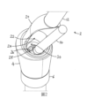
自以下參考附圖進行的對非限制性具體實例之詳細描述,本發明之其他細節及優勢將顯而易見,在該等附圖中:[圖1]為經完全組裝且附接至基牙的根據具體實例之工具總成的側視圖;[圖2]為自圖1之工具總成的下部部分之上方看的透視圖;[圖3]為圖1之工具總成的側向分解圖;及 [圖4]為圖1之工具總成的下部部分與基牙之間的接面之側向放大圖。 Other details and advantages of the present invention will be apparent from the following detailed description of non-limiting specific examples with reference to the accompanying drawings, in which: [Fig. 1] is a base fully assembled and attached to an abutment. A side view of the tool assembly of a specific example; [Figure 2] is a perspective view from above the lower part of the tool assembly of Figure 1; [Figure 3] is a side exploded view of the tool assembly of Figure 1; and [Fig. 4] is a side enlarged view of the interface between the lower part of the tool assembly of Fig. 1 and the abutment.
在下文中,相同的附圖標記表示相同部分,且除非本文中另外陳述,否則任一具體實例之任何元件、設計特徵或方法步驟可與任一其他具體實例之元件、設計特徵或方法步驟組合使用。 Hereinafter, like reference numerals refer to like parts, and unless otherwise stated herein, any element, design feature, or method step of any particular example may be used in combination with an element, design feature, or method step of any other particular example. .
在整個本說明書之描述及申請專利範圍中,除非上下文另外要求,否則單數涵蓋複數。特定而言,當使用不定冠詞時,除非上下文另外要求,否則本說明書應理解為預期複數以及單數。 Throughout the description and claims of this specification, the singular encompasses the plural unless the context otherwise requires. In particular, when the indefinite article is used, this specification is to be understood to contemplate the plural as well as the singular unless the context requires otherwise.
結合本發明之特定態樣、具體實例或實例描述之特徵、整體、特性、化合物或基團應理解為適用於本文中所描述之任何其他態樣、具體實例或實例,除非與其不相容。 Features, integers, characteristics, compounds or groups described in connection with a particular aspect, embodiment or instance of the invention are to be understood to apply to any other aspect, embodiment or instance described herein unless incompatible therewith.
在整個本說明書之描述及申請專利範圍中,術語「孔徑」及「孔」包括不限於任何孔徑、開口、孔、槽道、通道等。 Throughout the description and patent scope of this specification, the terms "aperture" and "hole" include, without limitation, any aperture, opening, hole, channel, channel, etc.
在整個本說明書之描述及申請專利範圍中,術語「傾斜」、「成角度」、「偏移」、「不重合」及「不平行」可互換使用,以指一組件的縱向軸線在使用中並不與第一組件待一起使用之另一組件(例如,牙齒植入物)的縱向軸線同軸。 Throughout the description and patent claims of this specification, the terms "tilt," "angled," "offset," "non-coincident," and "non-parallel" are used interchangeably to refer to the longitudinal axis of a component in use. Not coaxial with the longitudinal axis of another component with which the first component is to be used (eg, a dental implant).
除非另外指示,否則本文中所描述/說明之組件可由鈦或外科用鋼製成,及/或可使用車削及/或機械加工製造成。 Unless otherwise indicated, components described/illustrated herein may be made of titanium or surgical steel, and/or may be fabricated using turning and/or machining.
圖1為經完全組裝且附接至基牙4的根據具體實例之工具總成2的側視圖。如所說明,植入物6經組態以例如通過經由經塑形凹陷8接合植入物6之協作式固定元件(圖中未示)穩固地附接至已嵌入於患者之顎部(圖中未示)中的框架(圖中未示)。替代地,標記為6之元件可由與框架(圖中未示)成一
體之基座或支柱形成或構成該基座或支柱。
FIG. 1 is a side view of a
本發明考慮到在植入物6已牢固地固定於顎骨中時,將基牙4牢固地固定至植入物6或框架之要求。在較佳具體實例中,基牙4及植入物6具有鄰接之平坦或形狀擬合表面(圖1中未示),如10處所指示。
The present invention takes into account the requirement of firmly fixing the
根據本發明,工具總成2包括第一工具12及第二工具14。
According to the present invention, the
第一工具12具有伸長軸線A、經組態以在使用中接合基牙4之第一末端16,及第二末端18。在第一末端16處或附近的第一工具12之至少第一部分20具有周邊壁22。在具體實例中,周邊壁22可具有至多幾mm之厚度,例如至多3mm,及/或可至多為第一部分20之直徑的10%。
The
在第一工具12之第一部分20中且與壁22相對,第一開口24沿著第一部分20的全部或部分延伸。
In the
第一工具12之伸長軸線A與基牙4之孔徑、開口或第二接合元件42的軸線重合。第一工具12之伸長軸線A與植入物6(及當基牙安裝至植入物時,基牙4)之伸長軸線B並不重合/重疊。在此等兩個軸線之間存在介於5°與35°之間的角度α。
The axis of elongation A of the
植入物6(及當基牙安裝在植入物上時,基牙)之伸長軸線B實質上豎直。當植入物6以實質上豎直位置安裝於顎骨中時,第一工具12以角度α延伸/突出至患者之頰腔中。因此,可由牙科醫生容易地握緊並操縱第一工具連同第二工具並將其安裝至植入物。
The axis of elongation B of the implant 6 (and the abutment when mounted on the implant) is substantially vertical. When the
在本發明之上下文中,「實質上豎直」應理解為與設定在顎部中,且以實質上豎直角度在頰腔中突出的自然牙齒相同的角度。 In the context of the present invention, "substantially vertical" is to be understood as the same angle as a natural tooth set in the jaw and projecting in the buccal cavity at a substantially vertical angle.
然而,取決於植入物或固定至植入物的假牙之組態及其他因素,如顎部之骨骼品質、植入物之數目、植入物在口部中的位置(上顎、下顎、前牙、後牙)等,植入物可能以偏離豎直方向之角度植入顎部中。 However, it depends on the configuration of the implant or the denture fixed to the implant and other factors such as the bone quality of the jaw, the number of implants, the position of the implant in the mouth (upper jaw, lower jaw, anterior jaw). teeth, posterior teeth), etc., the implant may be implanted into the jaw at an angle away from the vertical direction.
如WO 2009/127880之圖8上所示的組態之一個缺點為,使用時手柄與螺絲刀此兩種工具彼此妨礙,因為自將該基牙安裝於患者口部中的牙科醫生之視角看,必須將螺絲刀插入手柄「後方」。因為手柄之妨礙,難以擰緊螺釘。然而,在本發明組態中,兩個工具並不彼此妨礙。經由第一工具之「前方」插入第二工具(螺絲刀),亦即其朝向頰腔定向。因此,可容易地在第一工具就位時插入第二工具。可在不受到如WO 2009/127880之圖8中的手柄之妨礙的情況下轉動螺絲刀。 One disadvantage of the configuration shown in Figure 8 of WO 2009/127880 is that the two tools, the handle and the screwdriver, interfere with each other when in use, since from the perspective of the dentist installing the abutment in the patient's mouth, The screwdriver must be inserted "behind" the handle. It is difficult to tighten the screws because of the obstruction of the handle. However, in the inventive configuration, the two tools do not interfere with each other. The second tool (screwdriver) is inserted "in front" of the first tool, ie it is oriented towards the buccal cavity. Therefore, the second tool can be easily inserted while the first tool is in place. The screwdriver can be turned without being hindered by the handle as in Figure 8 of WO 2009/127880.
簡單參考圖2,此為自圖1之工具總成2之下部部分上方看的透視圖。在軸向方向上敞開之第二開口26安置於第一末端16處。在具體實例中,第二開口26為圓形形狀。
Referring briefly to FIG. 2 , this is a perspective view from above the lower portion of the
根據本發明,第二工具14經組態以可釋放地接合固定元件28,如下文中更詳細地論述。
In accordance with the present invention, the
參考圖1及圖2,在第一開口24與第二開口26之間界定連續空間30,使得在使用中,(i)固定元件28或(ii)附接至第二工具14之固定元件28可穿過第一開口24及第二開口26,以准許使用第二工具14將基牙4牢固地固定至植入物6或框架,如下文中更詳細地論述。
Referring to Figures 1 and 2, a
返回至圖1,在具體實例中,壁22之至少部分32具有部分圓柱形形式。更特定地,在具體實例中,沿著壁22之至少部分32具有部分圓柱形形式,從而使得當在軸向橫截面中檢視時,形成於接合伸長軸線A之半徑與壁22之兩個周向末端中之每一者之間的角度為(i)120度或更多,(ii)150度或更多、180度或更多,或為180度。在具體實例中,具有部分圓柱形形式之部分32安置於第一末端16處或附近。
Returning to Figure 1, in the specific example, at
在具體實例中,第一工具12之第一部分20在第一工具12之長度的部分上延伸。更特定地,在具體實例中,第一工具12之第一部分20在第一工具
12之長度的(i)30至60%,(ii)35至55%,(iii)40至50%,(iv)45至50%或(v)50%上延伸。
In a specific example, the
在具體實例中,當在橫向橫截面中檢視時,壁22之至少部分32包含在第一末端16處或附近之矩形部分。
In a specific example, at
在具體實例中,由第一工具12的除了第一部分20外的部分形成的第一工具12之第二部分34包含可手握部分,或經組態以可釋放地接合用於由使用者操縱之手柄(圖中未示)。在具體實例中,當在橫向橫截面中檢視時,第一部分20包含在第二部分34附近之彎曲部分36。
In particular examples, the
在具體實例中,第一工具12之第一部分20具有比第一工具12之剩餘部分,例如第二部分34大的橫向尺寸(例如,直徑)。例如,第一部分20可具有為第一工具12之剩餘部分的100至300%之橫向尺寸(例如,直徑),從而使得第二工具可穿過其中插入且具有搖動/擺動空間。
In a specific example, the
圖3為圖1之工具總成2的側向分解圖。在具體實例中,在第一末端16處,第一工具12包括至少一個第一接合元件36,其經組態以用於經由基牙4上之協作式至少一個第二接合元件42可釋放地附接至基牙4。第一接合元件36可包含上面提供外部螺紋40之接合環38,及/或第二接合元件42可包含例如上面提供內部螺紋(圖中未示)之中空內環區段44。在替代具體實例中,在接合環38上提供內部螺紋,及/或在內環區段44上提供外部螺紋(圖中未示)。
FIG. 3 is a side exploded view of the
經由由壁22界定之第一開口24、由接合環38界定之第二開口26及內環區段44,固定元件28(較佳地附接至第二工具14,如圖3中所示)可由使用者自第一工具12之外部推進至基牙4內界定之腔室46中。
Via the
在具體實例中,在基牙4的與內環區段44相對之末端48處或附近,基牙4包括例如呈六角螺母形狀之外部形成物50,其用於接合植入物6中對應地塑形之凹陷(圖中未示),以便將基牙4以不可移動(亦即,不可旋轉)方
式收納在植入物6中。
In a specific example, at or near the
如圖3中所見,在第三(遠側)末端52處,第二工具14可包含至少一個第三接合元件54,其經組態以用於經由固定元件28上之協作式至少一個第四接合元件56可釋放地附接至固定元件28。在固定元件28的與第四接合元件56相對之末端處,固定元件可具有外部螺紋58或其他附接元件,以用於將對應附接元件(例如,內部螺紋)固定地接合於植入物6或框架內。
As seen in FIG. 3 , at the third (distal)
在具體實例中,固定元件28包含經組態以用於旋擰至植入物6或框架中的螺栓或螺釘。在具體實例中,協作式至少一個第三接合元件54及至少一個第四接合元件56包含協作式卡扣固定(棘爪固定)附接元件。亦即,第三接合元件54(例如,具有多個朝外偏置之突出部的滾珠)可經組態以使得第二工具14之遠端52能夠扣入第四接合元件56(例如,具有用於收納滾珠及/或突出部之內部凹陷或多個凹陷的螺栓頭部;圖中未示)中。
In a specific example, the
以引用方式整合於本文中之EP 3 541 318描述用於外科應用之螺釘與驅動器的組合,該驅動器用於驅動螺釘以用於將整形外科植入物緊固至骨骼或整形外科植入物,尤其為將牙齒組件緊固至可用於本發明目的的牙齒植入物。 EP 3 541 318, which is incorporated herein by reference, describes a combination of a screw and a driver for surgical applications, the driver being used to drive a screw for fastening an orthopedic implant to a bone or an orthopedic implant, Especially for fastening dental components to dental implants which can be used for the purposes of the present invention.
圖4為圖1之工具總成2的下部部分與基牙之間的接面之側向放大圖。第一工具12已可釋放地接合基牙4,使得至少一個第一接合元件36已(例如,以螺紋方式)接合基牙4上的協作式至少一個第二接合元件42。第三接合元件54已接合第四接合元件56,從而使得能夠將固定元件28向下推動(在箭頭B之方向上)至基牙4及植入物6中。此後,藉由使用者扭轉第二工具14之近端59(與遠端52相對),使用者可將固定元件28旋擰至植入物6或框架中。
FIG. 4 is an enlarged side view of the interface between the lower part of the
在具體實例中,此移動(及在箭頭B之方向上旋擰入)受到與基牙4上之肩部62接觸的圓錐形區段60限制。
In the specific example, this movement (and screwing in in the direction of arrow B) is limited by the
因此,根據具體實例,如下為使用上文所描述且本文中所說明之工具總成安裝基牙的方法(可在一定程度上變化步驟之次序)。首先,將第一工具12之第一末端16可釋放地附接至基牙4。接著,將第二工具14可釋放地附接至固定元件28。接下來,使第二工具14上之固定元件28穿過第一開口24及第二開口26。使用者接著將兩工具插入頰腔中且將基牙定位於植入物上。使用者可將兩工具固持在拇指與食指間並容易地使其就位,而無螺釘或基牙掉落之風險。使用者接著操縱第二工具14,以便使用固定元件28將基牙4附接至植入物6或框架。最後,自固定元件28拆卸第二工具14並通過第二開口26及第一開口24移除第二工具14。最後,自基牙4拆卸第一工具12。若使用者想要再次取出基牙,則應以反向次序施加上文步驟。
Thus, according to a specific example, here is a method for installing an abutment using the tool assembly described above and illustrated herein (the order of the steps may be varied to some extent). First, the first end 16 of the
雖然已參考在其各別實施中具有各種組件之調查裝置的具體實例描述具體實例,但應瞭解,其他具體實例利用此等及其他組件之其他組合及排列。 Although specific examples have been described with reference to specific examples of survey devices having various components in their respective implementations, it is understood that other specific examples utilize other combinations and arrangements of these and other components.
2:工具總成 2: Tool assembly
4:基牙 4:Abutment teeth
6:植入物 6: Implants
8:經塑形凹陷 8: Shaped depression
12:第一工具 12:First tool
14:第二工具 14: Second tool
18:第二末端 18:Second end
24:第一開口 24:First opening
28:固定元件 28:Fixed components
30:連續空間 30: continuous space
36:第一接合元件 36: First joining element
38:接合環 38:joint ring
40:外部螺紋 40:External thread
42:第二接合元件 42: Second joint element
44:內環區段 44: Inner ring section
46:腔室 46: Chamber
48:末端 48:end
50:外部形成物 50:External formation
52:第二工具之第三(遠側)末端 52: The third (far side) end of the second tool
54:第三接合元件 54:Third joint element
56:第四接合元件 56: Fourth joint element
58:外部螺紋 58:External thread
59:近端 59: Near end
Claims (14)
Applications Claiming Priority (2)
| Application Number | Priority Date | Filing Date | Title |
|---|---|---|---|
| LU101149A LU101149B1 (en) | 2019-03-11 | 2019-03-11 | Tool assembly for mounting of a dental prosthesis an method of mounting |
| LULU101149 | 2019-03-11 |
Publications (2)
| Publication Number | Publication Date |
|---|---|
| TW202038871A TW202038871A (en) | 2020-11-01 |
| TWI834836B true TWI834836B (en) | 2024-03-11 |
Family
ID=65767279
Family Applications (1)
| Application Number | Title | Priority Date | Filing Date |
|---|---|---|---|
| TW109107835A TWI834836B (en) | 2019-03-11 | 2020-03-10 | Tool assembly for mounting a dental abutment |
Country Status (9)
| Country | Link |
|---|---|
| US (1) | US20220079715A1 (en) |
| EP (1) | EP3937831B1 (en) |
| KR (1) | KR20210137062A (en) |
| CN (1) | CN113573661B (en) |
| CA (1) | CA3130870A1 (en) |
| ES (1) | ES2971706T3 (en) |
| LU (1) | LU101149B1 (en) |
| TW (1) | TWI834836B (en) |
| WO (1) | WO2020182833A1 (en) |
Citations (2)
| Publication number | Priority date | Publication date | Assignee | Title |
|---|---|---|---|---|
| WO2009127880A1 (en) * | 2008-04-18 | 2009-10-22 | Neoss Limited | Spacer element for use in a dental implant assembly |
| TW201100062A (en) * | 2009-06-18 | 2011-01-01 | jun-long Chen | 5 in 1 dental implant method and apparatus |
Family Cites Families (18)
| Publication number | Priority date | Publication date | Assignee | Title |
|---|---|---|---|---|
| SE516040C2 (en) * | 2000-03-23 | 2001-11-12 | Nobel Biocare Ab | Arrangement including spacer for implants and such spacer and screwdriver for spacer attachment |
| US7249949B2 (en) * | 2004-06-29 | 2007-07-31 | Lifecore Biomedical, Inc. | Internal connection dental implant |
| IL181989A (en) * | 2007-03-18 | 2011-11-30 | Ophir Fromovich | Angulated ball abutment |
| US8142193B2 (en) * | 2009-06-25 | 2012-03-27 | Bar Shalom Eliezer | Compound angular joint for connecting an abutment to a dental implant in a predefined angle |
| US20120322030A1 (en) * | 2010-02-18 | 2012-12-20 | Alpha Bio Tec Ltd. | Modular abutment system for tilted dental implants |
| EP2696800B1 (en) * | 2011-04-15 | 2019-03-27 | Jbsg Management LLC | Polyaxial dental implant system |
| SE538150C2 (en) * | 2012-07-11 | 2016-03-22 | Heraeus Kulzer Nordic Ab | A screw channel directing device for a dental superstructure and methods for manufacturing a dental superstructure |
| WO2015040250A1 (en) * | 2013-09-23 | 2015-03-26 | Esteban Xam-Mar Mangrane | Interface element for dental prostheses |
| MX2017004494A (en) * | 2014-10-12 | 2017-08-08 | T A G Medical Devices - Agriculture Coop Ltd | Angular dental abutment assembly. |
| WO2017016893A1 (en) * | 2015-07-24 | 2017-02-02 | Nobel Biocare Services Ag | Adapter for attaching a dental superstructure to a dental implant and dental assembly comprising the adapter |
| WO2017059221A1 (en) * | 2015-09-30 | 2017-04-06 | Implant Direct Sybron International Llc | Screw-retained abutment with off-axis feature and methods of making and using same |
| JP6921089B2 (en) * | 2016-01-29 | 2021-08-18 | ノベル バイオケア サーヴィシィズ アーゲー | Dental implants, implant tools for dental implants, and combinations of dental implants and implant tools |
| LU93307B1 (en) | 2016-11-15 | 2018-05-25 | Laboratoire Dentaire Hornbeck Jacques S A R L | Screwdriver and Screw for a surgical application |
| CN110087581B (en) * | 2016-12-16 | 2022-12-20 | 尼欧斯有限公司 | Dental abutment blank, method of manufacturing a dental abutment blank and method of manufacturing a dental prosthesis from such a blank |
| JP7014799B2 (en) * | 2016-12-28 | 2022-02-01 | ストラウマン ホールディング アーゲー | Guide piece and milling system |
| US11826224B2 (en) * | 2017-04-03 | 2023-11-28 | Implant Direct Sybron International Llc | Multi-unit dental assembly with off-axis feature |
| ES2828087T3 (en) * | 2017-05-29 | 2021-05-25 | Mis Implants Tech Ltd | Dental connection system |
| WO2019162446A1 (en) * | 2018-02-22 | 2019-08-29 | Nobel Biocare Services Ag | Position locator attachable to a dental component and dental assembly comprising the position locator |
-
2019
- 2019-03-11 LU LU101149A patent/LU101149B1/en active IP Right Grant
-
2020
- 2020-03-10 KR KR1020217030363A patent/KR20210137062A/en active Pending
- 2020-03-10 CN CN202080020384.7A patent/CN113573661B/en not_active Expired - Fee Related
- 2020-03-10 CA CA3130870A patent/CA3130870A1/en active Pending
- 2020-03-10 ES ES20708126T patent/ES2971706T3/en active Active
- 2020-03-10 EP EP20708126.6A patent/EP3937831B1/en active Active
- 2020-03-10 US US17/430,846 patent/US20220079715A1/en not_active Abandoned
- 2020-03-10 TW TW109107835A patent/TWI834836B/en not_active IP Right Cessation
- 2020-03-10 WO PCT/EP2020/056391 patent/WO2020182833A1/en not_active Ceased
Patent Citations (2)
| Publication number | Priority date | Publication date | Assignee | Title |
|---|---|---|---|---|
| WO2009127880A1 (en) * | 2008-04-18 | 2009-10-22 | Neoss Limited | Spacer element for use in a dental implant assembly |
| TW201100062A (en) * | 2009-06-18 | 2011-01-01 | jun-long Chen | 5 in 1 dental implant method and apparatus |
Also Published As
| Publication number | Publication date |
|---|---|
| ES2971706T3 (en) | 2024-06-06 |
| CN113573661B (en) | 2023-11-21 |
| EP3937831A1 (en) | 2022-01-19 |
| LU101149B1 (en) | 2020-09-18 |
| TW202038871A (en) | 2020-11-01 |
| CN113573661A (en) | 2021-10-29 |
| EP3937831C0 (en) | 2023-12-27 |
| US20220079715A1 (en) | 2022-03-17 |
| CA3130870A1 (en) | 2020-09-17 |
| EP3937831B1 (en) | 2023-12-27 |
| WO2020182833A1 (en) | 2020-09-17 |
| KR20210137062A (en) | 2021-11-17 |
Similar Documents
| Publication | Publication Date | Title |
|---|---|---|
| EP0630621B1 (en) | Anatomical restoration dental implant system with interlockable various shaped healing cap assembly and matching abutment member | |
| US5362235A (en) | Anatomical restoration dental implant system with interlockable angled abutment assembly | |
| US8469710B2 (en) | Dental implant system and method | |
| JP6014654B2 (en) | Multiaxial dental implant system | |
| US5297963A (en) | Anatomical restoration dental implant system with interlockable elliptical healing cap assembly and matching abutment member | |
| JP7630017B2 (en) | Omnidirectional multi-unit abutment system for screw-mounted dental prostheses | |
| US20080032263A1 (en) | Dental Implant System and Method | |
| US20160331489A1 (en) | A precision surgical guidance tool system and method for implementing dental implants | |
| TWI834836B (en) | Tool assembly for mounting a dental abutment | |
| KR101292417B1 (en) | torque lench for Implant fixture | |
| RU2720486C2 (en) | Kit for dental implantation comprising dental implant and prosthetic components designed to fix single denture in upper and lower jaws of patient | |
| JP4261981B2 (en) | Dental implant system | |
| US20070020581A1 (en) | Apparatus and method for installing and removing crowns from abutments |
Legal Events
| Date | Code | Title | Description |
|---|---|---|---|
| MM4A | Annulment or lapse of patent due to non-payment of fees |