JP2018175029A - Walking training device and walking training aid - Google Patents
Walking training device and walking training aid Download PDFInfo
- Publication number
- JP2018175029A JP2018175029A JP2017074710A JP2017074710A JP2018175029A JP 2018175029 A JP2018175029 A JP 2018175029A JP 2017074710 A JP2017074710 A JP 2017074710A JP 2017074710 A JP2017074710 A JP 2017074710A JP 2018175029 A JP2018175029 A JP 2018175029A
- Authority
- JP
- Japan
- Prior art keywords
- walking
- training device
- training
- walking training
- trainee
- Prior art date
- Legal status (The legal status is an assumption and is not a legal conclusion. Google has not performed a legal analysis and makes no representation as to the accuracy of the status listed.)
- Granted
Links
Images




Classifications
-
- A—HUMAN NECESSITIES
- A63—SPORTS; GAMES; AMUSEMENTS
- A63B—APPARATUS FOR PHYSICAL TRAINING, GYMNASTICS, SWIMMING, CLIMBING, OR FENCING; BALL GAMES; TRAINING EQUIPMENT
- A63B21/00—Exercising apparatus for developing or strengthening the muscles or joints of the body by working against a counterforce, with or without measuring devices
- A63B21/40—Interfaces with the user related to strength training; Details thereof
- A63B21/4027—Specific exercise interfaces
- A63B21/4033—Handles, pedals, bars or platforms
- A63B21/4035—Handles, pedals, bars or platforms for operation by hand
-
- A—HUMAN NECESSITIES
- A63—SPORTS; GAMES; AMUSEMENTS
- A63B—APPARATUS FOR PHYSICAL TRAINING, GYMNASTICS, SWIMMING, CLIMBING, OR FENCING; BALL GAMES; TRAINING EQUIPMENT
- A63B22/00—Exercising apparatus specially adapted for conditioning the cardio-vascular system, for training agility or co-ordination of movements
- A63B22/02—Exercising apparatus specially adapted for conditioning the cardio-vascular system, for training agility or co-ordination of movements with movable endless bands, e.g. treadmills
-
- A—HUMAN NECESSITIES
- A45—HAND OR TRAVELLING ARTICLES
- A45B—WALKING STICKS; UMBRELLAS; LADIES' OR LIKE FANS
- A45B9/00—Details
- A45B9/02—Handles or heads
-
- A—HUMAN NECESSITIES
- A61—MEDICAL OR VETERINARY SCIENCE; HYGIENE
- A61H—PHYSICAL THERAPY APPARATUS, e.g. DEVICES FOR LOCATING OR STIMULATING REFLEX POINTS IN THE BODY; ARTIFICIAL RESPIRATION; MASSAGE; BATHING DEVICES FOR SPECIAL THERAPEUTIC OR HYGIENIC PURPOSES OR SPECIFIC PARTS OF THE BODY
- A61H3/00—Appliances for aiding patients or disabled persons to walk about
- A61H3/008—Appliances for aiding patients or disabled persons to walk about using suspension devices for supporting the body in an upright walking or standing position, e.g. harnesses
-
- A—HUMAN NECESSITIES
- A61—MEDICAL OR VETERINARY SCIENCE; HYGIENE
- A61H—PHYSICAL THERAPY APPARATUS, e.g. DEVICES FOR LOCATING OR STIMULATING REFLEX POINTS IN THE BODY; ARTIFICIAL RESPIRATION; MASSAGE; BATHING DEVICES FOR SPECIAL THERAPEUTIC OR HYGIENIC PURPOSES OR SPECIFIC PARTS OF THE BODY
- A61H3/00—Appliances for aiding patients or disabled persons to walk about
- A61H3/02—Crutches
-
- A—HUMAN NECESSITIES
- A63—SPORTS; GAMES; AMUSEMENTS
- A63B—APPARATUS FOR PHYSICAL TRAINING, GYMNASTICS, SWIMMING, CLIMBING, OR FENCING; BALL GAMES; TRAINING EQUIPMENT
- A63B21/00—Exercising apparatus for developing or strengthening the muscles or joints of the body by working against a counterforce, with or without measuring devices
- A63B21/00178—Exercising apparatus for developing or strengthening the muscles or joints of the body by working against a counterforce, with or without measuring devices for active exercising, the apparatus being also usable for passive exercising
-
- A—HUMAN NECESSITIES
- A63—SPORTS; GAMES; AMUSEMENTS
- A63B—APPARATUS FOR PHYSICAL TRAINING, GYMNASTICS, SWIMMING, CLIMBING, OR FENCING; BALL GAMES; TRAINING EQUIPMENT
- A63B21/00—Exercising apparatus for developing or strengthening the muscles or joints of the body by working against a counterforce, with or without measuring devices
- A63B21/40—Interfaces with the user related to strength training; Details thereof
- A63B21/4027—Specific exercise interfaces
- A63B21/4033—Handles, pedals, bars or platforms
-
- A—HUMAN NECESSITIES
- A63—SPORTS; GAMES; AMUSEMENTS
- A63B—APPARATUS FOR PHYSICAL TRAINING, GYMNASTICS, SWIMMING, CLIMBING, OR FENCING; BALL GAMES; TRAINING EQUIPMENT
- A63B22/00—Exercising apparatus specially adapted for conditioning the cardio-vascular system, for training agility or co-ordination of movements
- A63B22/02—Exercising apparatus specially adapted for conditioning the cardio-vascular system, for training agility or co-ordination of movements with movable endless bands, e.g. treadmills
- A63B22/0235—Exercising apparatus specially adapted for conditioning the cardio-vascular system, for training agility or co-ordination of movements with movable endless bands, e.g. treadmills driven by a motor
-
- A—HUMAN NECESSITIES
- A63—SPORTS; GAMES; AMUSEMENTS
- A63B—APPARATUS FOR PHYSICAL TRAINING, GYMNASTICS, SWIMMING, CLIMBING, OR FENCING; BALL GAMES; TRAINING EQUIPMENT
- A63B22/00—Exercising apparatus specially adapted for conditioning the cardio-vascular system, for training agility or co-ordination of movements
- A63B22/20—Exercising apparatus specially adapted for conditioning the cardio-vascular system, for training agility or co-ordination of movements using rollers, wheels, castors or the like, e.g. gliding means, to be moved over the floor or other surface, e.g. guide tracks, during exercising
- A63B22/201—Exercising apparatus specially adapted for conditioning the cardio-vascular system, for training agility or co-ordination of movements using rollers, wheels, castors or the like, e.g. gliding means, to be moved over the floor or other surface, e.g. guide tracks, during exercising for moving a support element in reciprocating translation, i.e. for sliding back and forth on a guide track
- A63B22/203—Exercising apparatus specially adapted for conditioning the cardio-vascular system, for training agility or co-ordination of movements using rollers, wheels, castors or the like, e.g. gliding means, to be moved over the floor or other surface, e.g. guide tracks, during exercising for moving a support element in reciprocating translation, i.e. for sliding back and forth on a guide track in a horizontal plane
-
- A—HUMAN NECESSITIES
- A63—SPORTS; GAMES; AMUSEMENTS
- A63B—APPARATUS FOR PHYSICAL TRAINING, GYMNASTICS, SWIMMING, CLIMBING, OR FENCING; BALL GAMES; TRAINING EQUIPMENT
- A63B24/00—Electric or electronic controls for exercising apparatus of preceding groups; Controlling or monitoring of exercises, sportive games, training or athletic performances
- A63B24/0062—Monitoring athletic performances, e.g. for determining the work of a user on an exercise apparatus, the completed jogging or cycling distance
-
- A—HUMAN NECESSITIES
- A63—SPORTS; GAMES; AMUSEMENTS
- A63B—APPARATUS FOR PHYSICAL TRAINING, GYMNASTICS, SWIMMING, CLIMBING, OR FENCING; BALL GAMES; TRAINING EQUIPMENT
- A63B24/00—Electric or electronic controls for exercising apparatus of preceding groups; Controlling or monitoring of exercises, sportive games, training or athletic performances
- A63B24/0087—Electric or electronic controls for exercising apparatus of groups A63B21/00 - A63B23/00, e.g. controlling load
-
- A—HUMAN NECESSITIES
- A61—MEDICAL OR VETERINARY SCIENCE; HYGIENE
- A61H—PHYSICAL THERAPY APPARATUS, e.g. DEVICES FOR LOCATING OR STIMULATING REFLEX POINTS IN THE BODY; ARTIFICIAL RESPIRATION; MASSAGE; BATHING DEVICES FOR SPECIAL THERAPEUTIC OR HYGIENIC PURPOSES OR SPECIFIC PARTS OF THE BODY
- A61H2201/00—Characteristics of apparatus not provided for in the preceding codes
- A61H2201/16—Physical interface with patient
- A61H2201/1602—Physical interface with patient kind of interface, e.g. head rest, knee support or lumbar support
- A61H2201/1635—Hand or arm, e.g. handle
- A61H2201/1638—Holding means therefor
-
- A—HUMAN NECESSITIES
- A61—MEDICAL OR VETERINARY SCIENCE; HYGIENE
- A61H—PHYSICAL THERAPY APPARATUS, e.g. DEVICES FOR LOCATING OR STIMULATING REFLEX POINTS IN THE BODY; ARTIFICIAL RESPIRATION; MASSAGE; BATHING DEVICES FOR SPECIAL THERAPEUTIC OR HYGIENIC PURPOSES OR SPECIFIC PARTS OF THE BODY
- A61H2201/00—Characteristics of apparatus not provided for in the preceding codes
- A61H2201/16—Physical interface with patient
- A61H2201/1602—Physical interface with patient kind of interface, e.g. head rest, knee support or lumbar support
- A61H2201/164—Feet or leg, e.g. pedal
- A61H2201/1642—Holding means therefor
-
- A—HUMAN NECESSITIES
- A61—MEDICAL OR VETERINARY SCIENCE; HYGIENE
- A61H—PHYSICAL THERAPY APPARATUS, e.g. DEVICES FOR LOCATING OR STIMULATING REFLEX POINTS IN THE BODY; ARTIFICIAL RESPIRATION; MASSAGE; BATHING DEVICES FOR SPECIAL THERAPEUTIC OR HYGIENIC PURPOSES OR SPECIFIC PARTS OF THE BODY
- A61H2201/00—Characteristics of apparatus not provided for in the preceding codes
- A61H2201/50—Control means thereof
- A61H2201/5023—Interfaces to the user
- A61H2201/5043—Displays
-
- A—HUMAN NECESSITIES
- A61—MEDICAL OR VETERINARY SCIENCE; HYGIENE
- A61H—PHYSICAL THERAPY APPARATUS, e.g. DEVICES FOR LOCATING OR STIMULATING REFLEX POINTS IN THE BODY; ARTIFICIAL RESPIRATION; MASSAGE; BATHING DEVICES FOR SPECIAL THERAPEUTIC OR HYGIENIC PURPOSES OR SPECIFIC PARTS OF THE BODY
- A61H3/00—Appliances for aiding patients or disabled persons to walk about
-
- A—HUMAN NECESSITIES
- A63—SPORTS; GAMES; AMUSEMENTS
- A63B—APPARATUS FOR PHYSICAL TRAINING, GYMNASTICS, SWIMMING, CLIMBING, OR FENCING; BALL GAMES; TRAINING EQUIPMENT
- A63B22/00—Exercising apparatus specially adapted for conditioning the cardio-vascular system, for training agility or co-ordination of movements
- A63B2022/0094—Exercising apparatus specially adapted for conditioning the cardio-vascular system, for training agility or co-ordination of movements for active rehabilitation, e.g. slow motion devices
-
- A—HUMAN NECESSITIES
- A63—SPORTS; GAMES; AMUSEMENTS
- A63B—APPARATUS FOR PHYSICAL TRAINING, GYMNASTICS, SWIMMING, CLIMBING, OR FENCING; BALL GAMES; TRAINING EQUIPMENT
- A63B69/00—Training appliances or apparatus for special sports
- A63B69/0064—Attachments on the trainee preventing falling
Landscapes
- Health & Medical Sciences (AREA)
- General Health & Medical Sciences (AREA)
- Physical Education & Sports Medicine (AREA)
- Cardiology (AREA)
- Vascular Medicine (AREA)
- Life Sciences & Earth Sciences (AREA)
- Biophysics (AREA)
- Orthopedic Medicine & Surgery (AREA)
- Epidemiology (AREA)
- Pain & Pain Management (AREA)
- Rehabilitation Therapy (AREA)
- Animal Behavior & Ethology (AREA)
- Public Health (AREA)
- Veterinary Medicine (AREA)
- Rehabilitation Tools (AREA)
Abstract
【課題】歩行訓練において、訓練者自身が移動することなく常に掴まる場所がある歩行訓練装置での訓練から、実際の移動を伴う上に体重を預けられる安定的な支えがない通常の歩行路での訓練へスムーズに移行するための歩行訓練装置および歩行訓練補助具を提供する。【解決手段】無限軌道回転式の歩行面を有するトレッドミル131を備える歩行訓練装置100であって、歩行訓練者が把持する把持部を備え、把持部は、歩行訓練者による歩行面側への加重を支持可能であると共に、歩行面に平行な成分を含む方向に移動できる歩行訓練装置を提供する。このような構成で擬似的な杖を実現することにより、訓練者は、トレッドミルを用いた脚部の訓練に平行して、杖を操る上体の訓練を行うことができる。【選択図】図1An object of the present invention is to provide an ordinary walking path without a stable support that allows a trainee to actually hold his / her weight in addition to actual movement from training using a walking training device in which there is a place where a trainee can always grasp without moving. The present invention provides a walking training device and a walking training aid for smoothly transitioning to training in the field. A walking training device 100 including a treadmill 131 having a track-type rotating walking surface, comprising a gripper gripped by a walking trainee, wherein the gripping portion is directed to a walking surface side by the walking trainer. Provided is a walking training device that can support a weight and can move in a direction including a component parallel to a walking surface. By realizing a pseudo wand with such a configuration, the trainee can perform upper body training for operating the cane in parallel with leg training using a treadmill. [Selection diagram] Fig. 1
Description
本発明は、歩行訓練装置および歩行訓練補助具に関する。 The present invention relates to a walking training device and a walking training aid.
歩行に障害を持つ人達が歩行機能を回復するための装置として、トレッドミルを備えた歩行訓練装置が知られている。トレッドミルは、回転ベルトを備えており、訓練者は、回転ベルトの上をその回転に合わせて歩行することで訓練を行う。 A walk training device equipped with a treadmill is known as a device for people with disabilities in walking to recover their walking function. The treadmill is provided with a rotating belt, and the trainee trains by walking on the rotating belt in accordance with the rotation.
訓練者は、歩行訓練装置の手すり等に掴まりながら、回転ベルトの上を歩いて訓練を行う。そして、訓練のステージが進むと歩行訓練装置の利用を終え、例えば廊下などの通常の歩行路での歩行訓練に移行する。しかし、自身が移動することなく常に掴まる場所がある歩行訓練装置での訓練から、実際の移動を伴う上に体重を預けられる安定的な支えがない通常の歩行路での訓練への移行には、高いハードルがある。 The trainee walks on the rotating belt and performs training while grasping with the handrail or the like of the walking training device. And if the stage of training advances, utilization of a walk training device will be ended, and it will shift to walk training in the usual walkways, such as a corridor, for example. However, from the training in the walking training device where there is always a place to grab without moving itself, to the transition from training on a steady supportless ordinary walkway where you can put weight on with actual movement There are high hurdles.
通常の歩行路での訓練は、杖を使う段階から始めることが多いが、手すりに掴まる動作と杖を使う動作には大きな違いがあり、訓練者は、杖を適切に用いて自身の体重を支えながら歩くことが難しく、不安を覚えることが多かった。歩行訓練装置での訓練の段階で杖を適切に操る訓練も行うことが望ましいが、歩行面が回転しているという性質から、訓練者は、杖を適切な位置に突くことができない。回転していない場所を選んで突こうとすれば不自然な姿勢となり、有効な訓練にはならない。 Training on a regular walkway often starts with the use of a cane, but there is a big difference between the action of grasping the handrail and the action of using a cane, and the trainee should use his cane appropriately and use his cane weight. It was difficult to walk with support and often felt uneasy. Although it is desirable to conduct training to properly manipulate the cane at the stage of training with the walking training device, the rotating nature of the walking surface does not allow the trainee to prick the cane into a proper position. If you try to pick a place that is not rotating, it will be unnatural posture and it will not be an effective training.
本発明は、このような問題を解決するためになされたものであり、歩行訓練者が通常の歩行路での歩行訓練に短期間でスムーズに移行するための歩行訓練装置および歩行訓練補助具を提供するものである。 The present invention has been made to solve such problems, and provides a walking training device and a walking training aid for a walking trainee to smoothly transition to walking training on a normal walking path in a short period of time. It is provided.
本発明の第1の態様における歩行訓練装置は、無限軌道回転式の歩行面を有するトレッドミルを備える歩行訓練装置であって、歩行訓練者が把持する把持部を備え、把持部は、歩行訓練者による歩行面側への加重を支持可能であると共に、歩行面に平行な成分を含む方向に移動できる。 The walk training device according to the first aspect of the present invention is a walk training device provided with a tread mill having a walk surface with an endless track rotation type, comprising a grip portion gripped by a walk training person, the grip portion being a walk training While being able to support the weight on the side of the walking surface by a person, it is possible to move in a direction including a component parallel to the walking surface.
このような構成により、歩行訓練装置が擬似的な杖を備えることになり、歩行訓練者は、トレッドミルを用いた脚部の訓練に平行して、杖を操る上体の訓練を行うことができる。 With such a configuration, the walking training device will be equipped with a simulated walking stick, and the walking training person can train the upper body to manipulate the walking stick in parallel with the training of the leg using the treadmill. it can.
上記の歩行訓練装置において、把持部は、把持部よりも歩行面側に設定された仮想点を中心とする仮想球の表面に沿って移動可能であるように構成すると良い。更に、仮想点が歩行面上に位置するように、把持部の位置を調整できるように構成すると良い。このような構成を採用することにより、より実際の杖に近い使用感を得ることができる。 In the above-described walking training device, the gripping portion may be configured to be movable along the surface of a virtual sphere centered on a virtual point set closer to the walking surface than the gripping portion. Further, the position of the grip portion may be adjusted so that the virtual point is located on the walking plane. By adopting such a configuration, it is possible to obtain a feeling of use closer to that of a real cane.
上記の歩行訓練装置において、把持部は、上記の歩行面に平行な成分を含む方向に直交する方向へも移動できるように構成すると良い。このように構成すると、更に実際の杖に近い使用感を得ることができる。また、把持部の移動の基準位置に把持部を引き戻す弾性部材を備えるように構成すれば、より高度な安全性を確保することができる。また、歩行訓練者による把持部の移動方向への加重を支えられるように把持部の移動可能範囲を規制する規制部材を備えるように構成しても良い。このように規制部材を設ければ、実際の杖の機能としては存在しない、歩行訓練者が倒れる方向に対して荷重を支える機能を付与することができる。このような機能を付与することにより、歩行訓練装置での訓練から通常の歩行路での訓練への移行に対するハードルを下げることが期待できる。 In the above-described walking training device, the gripping portion may be configured to be movable in a direction orthogonal to the direction including the component parallel to the walking surface. With this configuration, it is possible to obtain a feeling of use closer to that of an actual wand. In addition, by providing an elastic member for pulling back the gripping portion at the reference position of the movement of the gripping portion, higher security can be ensured. In addition, a regulating member may be provided which regulates the movable range of the gripping portion so as to support the weight in the moving direction of the gripping portion by the walking trainer. By providing the restriction member in this manner, it is possible to provide the function of supporting the load in the direction in which the walking trainer falls down, which does not exist as the function of an actual cane. By giving such a function, it can be expected to lower the hurdles for the transition from training on the walking training device to training on the ordinary walking path.
本発明の第2の態様における歩行訓練補助具は、無限軌道回転式の歩行面を有するトレッドミルを備える歩行訓練装置に装着される歩行訓練補助具であって、歩行訓練者が把持する把持部と、歩行訓練装置に固定する固定部とを備え、把持部は、固定部を歩行訓練装置に固定した場合に、歩行訓練者による歩行面側への加重を支持可能であると共に、歩行面に平行な成分を含む方向に移動できる。 The walking training aid according to the second aspect of the present invention is a walking training aid mounted on a walking training device provided with a treadmill having a walking surface with an endless track rotation type, and the holding portion held by the walking trainee And a fixed portion fixed to the walking training device, the gripping portion being capable of supporting the weight on the side of the walking surface by the walking trainer when the fixed portion is fixed to the walking training device, It can move in the direction including parallel components.
このような構成による歩行訓練補助具を擬似的な杖として歩行訓練装置に装着することにより、歩行訓練者は、トレッドミルを用いた脚部の訓練に平行して、杖を操る上体の訓練を行うことができる。 By attaching the walking training aid having such a configuration to the walking training device as a simulated walking stick, the walking training person can train the upper body to manipulate the walking stick in parallel to the training of the leg using the treadmill. It can be performed.
本発明により、歩行訓練者は、歩行訓練装置を用いた歩行訓練から通常の歩行路での歩行訓練に、短期間でスムーズに移行することができる。 According to the present invention, the walking trainer can smoothly shift in a short period of time from walking training using the walking training device to walking training on a normal walking path.
以下、発明の実施の形態を通じて本発明を説明するが、特許請求の範囲に係る発明を以下の実施形態に限定するものではない。また、実施形態で説明する構成の全てが課題を解決するための手段として必須であるとは限らない。 Hereinafter, the present invention will be described through the embodiments of the invention, but the invention according to the claims is not limited to the following embodiments. Moreover, not all the configurations described in the embodiments are necessarily essential as means for solving the problems.
図1は、本実施形態にかかる歩行訓練装置100の概略斜視図である。歩行訓練装置100は、片麻痺などの障害を持つ障害者や脚力が衰えた高齢者である訓練者900が、歩行訓練を行うための装置である。歩行訓練装置100は、主に、全体の骨格を成すフレーム130、トレッドミル131、補助杖具110、脚部補助装置120、制御部133を備える。
FIG. 1 is a schematic perspective view of a
フレーム130は、床面に設置されるトレッドミル131上に立設されている。トレッドミル131は、無限軌道回転式の歩行面を有するトレッドミルであり、図示のモータにより歩行面としてのリング状のベルト132を回転させる。歩行訓練を行う訓練者900は、ベルト132に乗り、ベルト132の移動に合わせて歩行動作を試みる。
The
フレーム130は、モータやセンサの制御を行う制御部133や、訓練の進捗状況等を表示する表示部138などを支持している。また、訓練者900の頭上部付近で、ワイヤ134、136を巻き取ったり繰り出したりする引張部135、137を支持している。
The
脚部補助装置120は、訓練者900の患脚に装着され、訓練者900の歩行を補助する。例えば、膝関節の屈曲運動を補助するモータユニットを備えている。また、脚部補助装置120は、訓練者の足裏が受ける荷重を検出して制御部133へ出力する。脚部補助装置120は、上腿フレーム121を含み、上腿フレーム121には、ワイヤ134、136のそれぞれの端が固定されている。
The
引張部135は、訓練者900より前方に設置されており、足裏の荷重に応じて生成される制御部133の指令により、ワイヤ134を巻き取ったり繰り出したりする。引張部137は、訓練者900より後方に設置されており、同様に制御部133の指令によりワイヤ136を巻き取ったり繰り出したりする。これらを繰り返すことにより、上腿フレーム121を前方へ引き上げて訓練者900の振り出し動作をアシストしたり、後方へ引き上げて訓練者900の蹴り出し動作をアシストしたりする。制御部133は、引張部135、137を制御する他にも、ベルト132の回転移動や表示部138の表示なども制御する。
The
フレーム130は、図示するように、訓練者900を取り囲むように構造化されており、補助杖具110を取り付ける取付バー130aを含む。補助杖具110は、後に詳述するように、訓練者900が把持することにより擬似的な杖として機能する。したがって、補助杖具110は、訓練者900が把持可能なように取付バー130aに装着される。取付バー130aは、ベルト132の移動方向である前後方向に沿って伸延する棒状フレームであり、歩行訓練装置100においてはフレーム130に対して固定された不動箇所である。取付バー130aは、訓練者900が補助杖具110を利用する訓練に至る前の段階では、訓練者900が自身の体重を支えるために掴まる手すりとして機能する。
The
取付バー130aは、訓練者900の体格や姿勢に合わせて高さを調整できるように、骨格フレームから支持されている。具体的には、取付バー130aを支える調整バー130bが、骨格フレームに立設された垂直バー130cに対して上下方向に複数箇所で位置調整ができるように、フック130dが設けられている。また、取付バー130aは、補助杖具110の取付位置を前後方向に調整できるように、一定の直径の棒形状を成す。図1では、訓練者900の右側の取付バー130aに補助杖具110を装着した様子を示すが、左手で把持できる位置にも補助杖具110を装着可能なように、左側にも取付バー130a等が設けられている。
The
なお、図示するように、歩行訓練装置100を設置する床面と平行な平面をxy平面とし、ベルト132の移動方向をx方向とする。また、床面に対して垂直である鉛直方向をz軸とする。以下の説明における各図には、図1と同じ座標系を記して各部材の相対的な位置関係や向きを示す。
As illustrated, a plane parallel to the floor surface on which the walking
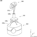
図2は、補助杖具110の外観斜視図である。補助杖具110は、訓練者900が把持する把持部200と、歩行訓練装置100の不動箇所に装着する装着部401を含む不動部400と、把持部200と不動部400を繋ぐ連結部300とから成る。把持部200は、不動部400に対して相対的に移動できるように、連結部300を介して不動部400に連接されている。より具体的には、補助杖具110は、把持部200が歩行面として機能するベルト132に平行な成分を含む方向に移動できるように、取付バー130aに固定される。なお、把持部200は、訓練者900が握りやすいようにz軸周りにも回転可能であり、図2の様子は、図1の様子に比べて把持部200が90度回転した様子を表している。
FIG. 2 is an external perspective view of the
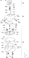
補助杖具110の更に詳細な構成について説明する。図3は、補助杖具110の主要部品を分解して表す分解斜視図である。
A more detailed configuration of the
把持部200は、主に、グリップ201、シャフト202、グリッププレート203によって構成されている。グリップ201は、訓練者900が直接的に把持する部品であり、例えばC字状に形成された樹脂の中央部に、グリップ性を高めるウレタンが巻き付けられている。グリッププレート203は、グリップ201とシャフト202を取り付けるプレートであり、例えばステンレス素材によって形成される。シャフト202は、鉛直方向に伸延する円柱状部品である。シャフト202は、円柱表面の一部が摺動面202aとして円滑に形成されている。また、グリッププレート203に取り付けられる上端部とは反対側の下端部には、コイルスプリング310の一端を係止する係止部202bが設けられている。
The
連結部300は、主に、コイルスプリング310、シャフトシリンダ320、球面スライダ330、コイルスプリング340によって構成されている。シャフトシリンダ320は、シャフト202と対向する上端側が円筒状に形成されており、球面スライダ330と対向する下端側が中実の円柱状に形成されている。円柱状に形成された下端側は、直径が若干小さく形成されており、嵌合軸320bとして機能する。
The connecting
円筒状に形成された円筒空間内の下端には、コイルスプリング310の他端を係止する係止部が設けられており、コイルスプリング310の他端は、当該係止部に係止される。すなわち、コイルスプリング310は、一端でシャフト202に接続され、他端でシャフトシリンダ320に接続されている。そして、コイルスプリング310は、シャフトシリンダ320の円筒空間に収容される。
A locking portion for locking the other end of the
シャフト202のうち摺動面202aが設けられた下端部は、摺動面202aがシャフトシリンダ320の内周面320aと上下方向に摺動可能なように、シャフトシリンダ320の円筒空間に収められる。このようにシャフト202とシャフトシリンダ320がコイルスプリング310の収縮力によって互いに引き合うように接続されることにより、把持部200は、シャフトシリンダ320側へ付勢された状態となる。なお、シャフト202は、摺動面202aの上端側に段差を有し、この段差がシャフトシリンダ320の上端面と干渉することで、シャフト202が規定された長さ以上に円筒空間に引き込まれることを防止している。シャフト202の段差がシャフトシリンダ320の上端面と接する状態が、把持部200の鉛直方向における基準位置である。したがって、コイルスプリング310は、訓練者900が操作しない場合に把持部200を基準位置に引き戻す弾性部材としての機能を担う。
The lower end portion of the
また、コイルスプリング310は、訓練者900の引張りに対して伸びきらない程度の弾性力を有し、訓練者900のグリップ操作により上側方向に過大な荷重をかけられたとしても、その荷重を受け止めることができる。換言すれば、コイルスプリング310は、訓練者900が姿勢を崩しそうな場合に、主に垂直方向の荷重を受けて体を支える機能を担う。
Also, the
球面スライダ330は、頂部を上向きにした浅くて厚みのあるすり鉢形状を成し、頂部にはシャフトシリンダ320の嵌合軸320bを嵌合させる嵌合孔330aが設けられている。シャフトシリンダ320は、嵌合軸320bが嵌合孔330aに嵌合され、球面スライダ330の下面側から取付ビス331によって固定されることにより、球面スライダ330と一体化される。球面スライダ330は、例えばナイロン樹脂によって形成される。
The
球面スライダ330は、コイルスプリング340の一端を係止する係止部330bを縁部端面に有する。係止部330bは例えば120度間隔で3箇所設けられている。すなわち、球面スライダ330の縁部端面には、放射方向に伸延するように3つのコイルスプリング340が接続されている。
The
不動部400は、主に、カバー410、スプリング台420、上部ベース430、下部ベース440によって構成されている。上部ベース430、下部ベース440は、装着部401として機能する。
The
上部ベース430は、円柱体の一端面である上面が一定の曲率半径の球面形状に形成された形状を成す。球面形状の表面であるスライド受面430aは、球面スライダ330が摺動する摺動面としての役割を担う。また、上部ベース430は、円柱体の他端面である下面に、取付バー131aを挟み込むための半円柱状の固定溝430dが形成されている。上部ベース430は、例えばナイロン樹脂によって形成される。
The
スプリング台420は、上部ベース430のスライド受面430aを周縁部で円環状に取り囲む部品である。スプリング台420は、z軸方向に貫通するビス孔420aが周縁部に120度間隔で設けられている。スライド受面430aには、ビス孔420aに対応する位置に下穴430bが設けられており、スプリング台420は、ビス孔420aを貫通して下穴430bに螺合するビス421によってスライド受面430aに固定される。
The
スプリング台420は、球面スライダ330がスライド受面430a上を摺動する場合の、球面方向における規制部材としての役割を担う。すなわち、スプリング台420は、訓練者900のグリップ操作により球面の外側方向に過大な荷重をかけられたとしても、その荷重を受け止めて、球面スライダ330の移動を規制する。換言すれば、訓練者900が姿勢を崩しそうな場合に、主に水平方向の荷重を受けて体を支える機能を担う。
The spring stand 420 plays a role as a restricting member in the spherical direction when the
スプリング台420の内周面には、球面スライダ330に取り付けられたコイルスプリング340の先端を係止する係止部が設けられている。球面スライダ330は、コイルスプリング340の弾性力により、スライド受面430a側に付勢されると共に、訓練者900の操作が無い状態においてスライド受け面430aの頂部で釣り合いを保つ。この釣り合い位置は、球面スライダ330の球面方向における基準位置である。コイルスプリング340は、把持部200が操作されて球面スライダ330が移動した場合に、球面スライダ330を基準位置に引き戻す弾性部材としての機能を担う。
The inner circumferential surface of the
カバー410は、球面スライダ330のz軸方向への移動を規制する部材である。全体としては上部ベース430に倣う形状を成し、球面形状の頂部には、球面スライダ330に接続されたシャフトシリンダ320の移動を妨げないように、カバー開口410aが設けられている。また、側面には、ビス孔410bが設けられている。上部ベース430の側面には、ビス孔410bに対応する位置に下穴430cが設けられており、カバー410は、ビス孔410bを貫通して下穴430cに螺合するビス411によって上部ベース430に固定される。
The
カバー410は、球面スライダ330がスライド受面430a上のいずれの位置にあっても球面スライダ330の一部を覆うので、訓練者900のグリップ操作により上側方向に過大な荷重をかけられたとしても、その荷重を受け止めて、球面スライダ330の引き抜けを防止する。換言すれば、カバー410は、訓練者900が姿勢を崩しそうな場合に、主に垂直方向の荷重を受けて体を支える機能を担う。
Since the
下部ベース440は、円柱形状を成し、一端面である上面に取付バー131aを挟み込むための半円柱状の固定溝440aが形成されている。下部ベース440は、例えばナイロン樹脂によって形成される。
The lower base 440 has a cylindrical shape, and a
下部ベース440は、円柱形状の軸方向であるz軸方向に貫通するように4つのボルト孔440bが設けられている。上部ベース430の下面には、ボルト孔440bに対応する位置に下穴が設けられており、下部ベース440は、ボルト孔440bを貫通して下穴に螺合する固定ボルト441によって上部ベース430に固定される。すなわち、上部ベース430の固定溝430dと下部ベース440の固定溝440aが取付バー131aを挟み込んで固定されるので、補助杖具110の全体が取付バー131aに固定されることになる。
The lower base 440 is provided with four
次に把持部200の移動方向について説明する。図4は、把持部200の移動方向を説明する図である。図4は、把持部200と連結部300と不動部400の相対的な関係を簡易的に示す図であり、図3で説明した部品のいくつかを省いて示している。
Next, the moving direction of the
まず、連結部300は、スライド面330cがスライド受面430a上を摺動することにより、球面方向に移動可能である。スライド受面430aは、図示するように、上凸の球面である。換言すると、スライド受面430aは、把持部200よりも床面側に設定された仮想点を中心とする仮想球の表面に沿う形状である。したがって、連結部300に接続された把持部200は、スライド受面430aに倣って移動可能である。
First, the connecting
そして、把持部200は、摺動面202aが内周面320aに接して摺動することにより、鉛直方向に移動可能である。より正確には、シャフトシリンダ320は球面スライダ330に立設されているので、シャフト202の移動方向は、そのときの球面スライダ330の位置におけるスライド受面430aの法線方向である。いずれにしても、把持部200は、鉛直方向の成分を含むように移動可能である。このように、球面方向への移動と鉛直方向への移動が合成され、把持部200は、一定空間内で三次元的に移動可能となる。
The
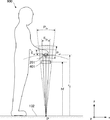
図5は、把持部200の移動範囲を説明する図である。図は、トレッドミル131のベルト132に訓練者900が乗って把持部200のグリップ201を把持した様子を示す。
FIG. 5 is a diagram for explaining the movement range of the
図においてグリップ201は、非荷重状態の基準位置にある。基準位置は、訓練者900が把持しやすい位置となるように、装着部401の取付位置が調整される。特に、グリップ201を通る鉛直線とベルト132の歩行面とが交わる点Pが、グリップ201の球面方向への移動における仮想球の中心点となるように、取付位置が調整されることが好ましい。この場合の球面の曲率半径は、図示するようにr0である。このようにr0が定められると、グリップ201の球面方向の動きが、実際の杖を突いて歩行する場合の杖の把持部の動きとほぼ一致するので、実際の杖による歩行訓練へ移行するための訓練を行う良い環境となる。
In the figure, the
補助杖具110がこのように設置されると、グリップ201は、点Pを中心としてEhrの範囲で揺動可能となる。また、グリップ201は鉛直方向にEvrの範囲で移動できるので、全体としてグリップ201が移動できる空間は、Ehrの範囲とEvrの範囲で囲まれる斜線で示す空間となる。この空間は、Phrの範囲とPvrの範囲で囲まれる、訓練者900が腕の移動程度で動かせる手の範囲(ドットで示す)に包含されることが好ましい。このようにグリップ201の移動範囲を規制すれば、訓練者900は、姿勢を崩しそうになったときにグリップ201に体重を預けることができるので、転倒を免れやすい。移動範囲の規制は、図3を用いて説明したように、球面方向についてはスプリング台420やコイルスプリング340が、鉛直方向についてはカバー410やコイルスプリング310が、それぞれの移動方向への加重を支えることで実現される。
When the
なお、補助杖具110は取付バー131aに固定されているので、補助杖具110は、訓練者900がグリップ201を床面方向へ押しつける加重(歩行面側への加重)も、もちろん受け止められる。訓練者900は、グリップ201を床面方向に押しつけて体重を預けることで、足の振り出し動作や蹴り出し動作の労力を軽減することができる。
In addition, since the
補助杖具110のいくつかの変形例について説明する。図6は、他の実施例における補助杖具510の移動方向を説明する図である。図6は、図4と同様に、把持部200と連結部300と不動部400の相対的な関係を簡易的に示す図である。補助杖具510は、主に補助杖具110における球面スライダ330と上部ベース430の構成が、補助杖具110と異なる。
Several variations of the
補助杖具510は、球面スライダ330の代わりに平面スライダ511を有する。平面スライダ511は、スライド面511aが平面である。また、補助杖具510は、上部ベース430の代わりに上部ベース512を有する。上部ベース512の上面であるスライド受面512aは、スライド面511aが摺動する摺動面であり、平面である。
The
すなわち、把持部200は、鉛直軸に直交するスライド面511aに沿って、平面方向へ移動可能である。なお、鉛直方向へは、補助杖具110と同様に移動可能である。このような簡易的な構成であっても、実際の杖を突いて歩行する場合の杖の把持部の動きをある程度再現することができる。
That is, the
図7は、更に他の実施例における補助杖具530の移動方向を説明する図である。図7は、図4と同様に、把持部200と連結部300と不動部400の相対的な関係を簡易的に示す図である。補助杖具530は、主に連結部300が把持部200に固定されている点で、補助杖具110と異なる。
FIG. 7 is a view for explaining the moving direction of the
具体的には、補助杖具110におけるシャフトシリンダ320に対応するシャフトシリンダ531が、グリッププレート203に、スプリングコイル等を介在すること無く直接的に固定されている。つまり、把持部200は、球面方向に移動可能であって、鉛直方向へは移動しない。このような簡易的な構成であっても、実際の杖の機能の一部である、平面方向への荷重を支える機能を再現することができる。
Specifically, a
図8は、参考例としての他の実施例における補助杖具520の移動方向を説明する図である。図8は、図4と同様に、把持部200と連結部300と不動部400の相対的な関係を簡易的に示す図である。補助杖具520は、主に連結部300が不動部400に固定されている点で、補助杖具110と異なる。
FIG. 8 is a view for explaining the moving direction of the
具体的には、補助杖具110におけるシャフトシリンダ320に対応するシャフトシリンダ521が、補助杖具110における上部ベース430に対応する上部ベース522に、固定して立設されている。つまり、把持部200は、鉛直方向の一方向に移動可能であって、球面あるいは平面方向へは移動しない。平面方向へは移動しないので、実際の杖に比較すると使用感は低下するものの、上下方向への荷重を支える機能については再現することができる。
Specifically, a
以上説明した各補助杖具は、把持部の移動範囲を規制する規制部材を備えている。規制部材は、スプリング台420のように、明確に移動範囲を取り囲む構成であっても良いし、コイルスプリング310のように、通常の荷重で想定される伸びの範囲が規制される移動範囲となるような弾性部材を利用しても良い。このように規制部材を設ければ、実際の杖の機能としては存在しない、訓練者900が倒れる方向に対して荷重を支える機能を付与することができる。このような機能を付与することにより、歩行訓練装置での訓練から通常の歩行路での訓練への移行に対するハードルを下げることが期待できる。すなわち、訓練者900は、歩行訓練装置での訓練の段階から杖を操る操作を徐々に体得することができるので、通常の歩行路における訓練へ移行した後には、スムーズに杖を使いこなせることが期待できる。
Each of the auxiliary canes described above is provided with a restricting member that restricts the movement range of the grip portion. The restricting member may be configured to clearly surround the moving range like the
また、杖を操る操作を徐々に体得する観点からは、把持部を把持する移動空間においては移動範囲を規制しない補助杖具を用意しても良い。移動範囲を事実上規制しない構成であれば、より実際の杖の機能に近づけることができるので、移動範囲を規制する補助杖具による訓練の後に、移動範囲を規制しない補助杖具による訓練を行うと良い。ただし、移動範囲を規制しない補助杖具も、実際の杖と同様に、把持部の床面方向への加重は支えられるようにすることが望ましい。 Further, from the viewpoint of gradually acquiring the operation of operating the wand, an auxiliary wand that does not restrict the movement range may be prepared in the movement space in which the holding portion is held. If the configuration that does not restrict the movement range in practice can be closer to the function of the actual cane, after training with the auxiliary cane that restricts the movement range, training with the auxiliary cane that does not restrict the movement range is performed It is good. However, it is desirable that an auxiliary wand that does not restrict the movement range be able to support the load of the grip portion in the floor direction, as with an actual wand.
また、補助杖具は、歩行訓練装置100に着脱可能な歩行訓練補助具としてではなく、歩行訓練装置に固定的に装備されたものであっても構わない。この場合、不動部は、歩行訓練装置100の不動部の一部として設けられていても良い。
In addition, the auxiliary cane may not be a walking training aid that can be attached to and detached from the walking
100 歩行訓練装置、110 補助杖具、120 脚部補助装置、121 上腿フレーム、130 フレーム、130a 取付バー、130b 調整バー、130c 垂直バー、130d フック、131 トレッドミル、132 ベルト、133 制御部、134、136 ワイヤ、135、137 引張部、138 表示部、200 把持部、201 グリップ、202 シャフト、202a 摺動面、202b 係止部、203 グリッププレート、300 連結部、310 コイルスプリング、320 シャフトシリンダ、320a 内周面、320b 嵌合軸、330 球面スライダ、330a 嵌合孔、330b 係止部、330c スライド面、331 取付ビス、340 コイルスプリング、400 不動部、401 装着部、410 カバー、410a カバー開口、410b ビス孔、411 ビス、420 スプリング台、420a ビス孔、421 ビス、430 上部ベース、430a スライド受面、430b、430c 下穴、430d 固定溝、440 下部ベース、440a 固定溝、440b ボルト孔、441 固定ボルト、510、520、530 補助杖具、511 平面スライダ、511a スライド面、512 上部ベース、512a スライド受面、521 シャフトシリンダ、522 上部ベース、531 シャフトシリンダ、900 訓練者
DESCRIPTION OF
Claims (7)
歩行訓練者が把持する把持部を備え、
前記把持部は、前記歩行訓練者による前記歩行面側への加重を支持可能であると共に、前記歩行面に平行な成分を含む方向に移動できる歩行訓練装置。 A walking training device comprising a treadmill having a rolling surface with an endless track rotation type, comprising:
It has a grip that a walker trains to hold,
A walking training device capable of supporting the weight on the side of the walking surface by the walking trainer and capable of moving in a direction including a component parallel to the walking surface.
歩行訓練者が把持する把持部と、
前記歩行訓練装置に固定する固定部と
を備え、
前記把持部は、前記固定部を前記歩行訓練装置に固定した場合に、前記歩行訓練者による前記歩行面側への加重を支持可能であると共に、前記歩行面に平行な成分を含む方向に移動できる歩行訓練補助具。 A walking training aid mounted on a walking training device comprising a treadmill having a rolling surface with an endless track rotation type, comprising:
A grip held by the walking trainer;
And a fixed part fixed to the walking training device,
The holding portion is capable of supporting the weight on the side of the walking surface by the walking trainer when the fixing portion is fixed to the walking training device, and moves in a direction including a component parallel to the walking surface. Walking training aids that can.
Priority Applications (5)
| Application Number | Priority Date | Filing Date | Title |
|---|---|---|---|
| JP2017074710A JP6776985B2 (en) | 2017-04-04 | 2017-04-04 | Walking training device and walking training aid |
| EP18159426.8A EP3384967B1 (en) | 2017-04-04 | 2018-03-01 | Walking training apparatus and walking training assistance device |
| US15/925,831 US10675503B2 (en) | 2017-04-04 | 2018-03-20 | Walking training apparatus and walking training assistance device |
| KR1020180037172A KR102080814B1 (en) | 2017-04-04 | 2018-03-30 | Walking training apparatus and walking training assistance device |
| CN201810282506.4A CN108686337B (en) | 2017-04-04 | 2018-04-02 | Walking training equipment and walking training aids |
Applications Claiming Priority (1)
| Application Number | Priority Date | Filing Date | Title |
|---|---|---|---|
| JP2017074710A JP6776985B2 (en) | 2017-04-04 | 2017-04-04 | Walking training device and walking training aid |
Publications (2)
| Publication Number | Publication Date |
|---|---|
| JP2018175029A true JP2018175029A (en) | 2018-11-15 |
| JP6776985B2 JP6776985B2 (en) | 2020-10-28 |
Family
ID=61526735
Family Applications (1)
| Application Number | Title | Priority Date | Filing Date |
|---|---|---|---|
| JP2017074710A Active JP6776985B2 (en) | 2017-04-04 | 2017-04-04 | Walking training device and walking training aid |
Country Status (5)
| Country | Link |
|---|---|
| US (1) | US10675503B2 (en) |
| EP (1) | EP3384967B1 (en) |
| JP (1) | JP6776985B2 (en) |
| KR (1) | KR102080814B1 (en) |
| CN (1) | CN108686337B (en) |
Families Citing this family (7)
| Publication number | Priority date | Publication date | Assignee | Title |
|---|---|---|---|---|
| JP7103307B2 (en) * | 2019-06-07 | 2022-07-20 | トヨタ自動車株式会社 | Gait training system and control program of gait training system |
| CN110368267A (en) * | 2019-07-30 | 2019-10-25 | 新乡医学院第一附属医院(河南省结核病医院) | A kind of walking rehabilitation nursing device |
| CN111658439B (en) * | 2020-07-03 | 2022-04-12 | 焦磊 | Lower limb auxiliary walking rehabilitation device |
| US11285357B1 (en) * | 2020-07-23 | 2022-03-29 | Kurt Gorin | Physical therapy boot |
| CN114099255B (en) * | 2021-11-26 | 2024-09-20 | 复旦大学附属儿科医院 | Child walking training nursing supporting equipment |
| US20230256282A1 (en) * | 2022-02-16 | 2023-08-17 | Omar Santos | Parallel Bar Stand Assistance Device |
| US12383786B2 (en) * | 2023-01-05 | 2025-08-12 | Giuseppe Garufi | Grip device for cable-connected exercise devices |
Citations (5)
| Publication number | Priority date | Publication date | Assignee | Title |
|---|---|---|---|---|
| JP2001037908A (en) * | 1999-07-29 | 2001-02-13 | Hitachi Techno Eng Co Ltd | Walking training equipment |
| US20050255971A1 (en) * | 2004-05-14 | 2005-11-17 | Solomon Richard D | Variable unweighting and resistance training and stretching apparatus for use with a cardiovascular or other exercise device |
| JP2009261778A (en) * | 2008-04-28 | 2009-11-12 | Nikon Corp | Handle instrument |
| US20150335940A1 (en) * | 2014-05-21 | 2015-11-26 | Cynthia Louise Johnson | Patient aid devices, particularly for mobile upper extremity support in railed devices such as parallel bars and treadmills |
| WO2016002885A1 (en) * | 2014-07-03 | 2016-01-07 | 帝人ファーマ株式会社 | Rehabilitation assistance device and program for controlling rehabilitation assistance device |
Family Cites Families (45)
| Publication number | Priority date | Publication date | Assignee | Title |
|---|---|---|---|---|
| US4342452A (en) * | 1980-01-25 | 1982-08-03 | Summa H Wayne | Treadmill device |
| US4529194A (en) * | 1983-04-18 | 1985-07-16 | Gary Haaheim | Cardiovascular exercise machine |
| JPH01128390A (en) | 1987-11-11 | 1989-05-22 | Matsushita Electric Ind Co Ltd | self temperature control heater |
| US4890495A (en) * | 1988-09-16 | 1990-01-02 | Slane Stephen M | Device for determining the push/pull capabilities of a human subject |
| NL9000946A (en) * | 1990-04-20 | 1991-11-18 | Pieter Jan Van Leeuwen | Cross-country ski training equipment - has horizontal rolling or gliding footplates and hand grips |
| US5085426A (en) * | 1990-07-30 | 1992-02-04 | Precor Incorporated | Integrated drive and elevation system for exercise apparatus |
| US5499955A (en) * | 1993-01-21 | 1996-03-19 | Smith & Nephew Rolyan, Inc. | Patient support for use with parallel bars |
| JPH11128390A (en) | 1997-10-27 | 1999-05-18 | Hitachi Ltd | Walking training machine |
| US6821233B1 (en) * | 1998-11-13 | 2004-11-23 | Hocoma Ag | Device and method for automating treadmill therapy |
| JP2001009063A (en) * | 1999-06-30 | 2001-01-16 | Yunimekku:Kk | Tilting table device for exercise loading device |
| ATE359850T1 (en) * | 2000-02-01 | 2007-05-15 | Univ Maryland | DOUBLE-SIDED ARM TRAINER |
| US20040204294A2 (en) * | 2000-12-29 | 2004-10-14 | William Wilkinson | Exercise device for exercising upper body simultaneously with lower body exercise |
| US6908414B1 (en) * | 2001-06-06 | 2005-06-21 | Lee A. Roadman | Interactive treadmill |
| US6837830B2 (en) * | 2002-11-01 | 2005-01-04 | Mark W. Eldridge | Apparatus using multi-directional resistance in exercise equipment |
| US7510511B2 (en) * | 2005-07-11 | 2009-03-31 | Von Detten Volker | Exercise treadmill having a simulated cobblestone running surface |
| US7153240B1 (en) * | 2005-09-08 | 2006-12-26 | Taiwan Bicycle Industry R&D Center | Medical gymnastic treadmill |
| US7775943B2 (en) * | 2006-02-15 | 2010-08-17 | Vittone Suzanne R | Resistance band exercise machine |
| US8007409B2 (en) * | 2007-11-06 | 2011-08-30 | Ellis Joseph K | Exercise treadmill for simulating a pushing action and exercise method therefor |
| US8172729B2 (en) * | 2009-11-16 | 2012-05-08 | Ellis Joseph K | Exercise treadmill for simulating pushing and pulling actions and exercise method therefor |
| US8147386B2 (en) * | 2008-10-28 | 2012-04-03 | Avero Fitness Llc | Integral treadmill resistance training apparatus |
| CN101518490A (en) * | 2009-03-26 | 2009-09-02 | 上海大学 | Active partial body weight support treadmill training device and active partial body weight support treadmill training method |
| US8308618B2 (en) * | 2009-04-10 | 2012-11-13 | Woodway Usa, Inc. | Treadmill with integrated walking rehabilitation device |
| CN101879115A (en) * | 2009-05-06 | 2010-11-10 | 高玉峰 | Walking weight-losing training machine |
| CN201518816U (en) | 2009-10-27 | 2010-07-07 | 齐威国际股份有限公司 | Structure of walking stick with omni-directional support |
| US8708842B2 (en) * | 2010-10-04 | 2014-04-29 | Eden Variety Products, Llc | Soccer training apparatus |
| US9227101B2 (en) * | 2012-01-13 | 2016-01-05 | Anthony Maguire | Endless belt multi-function training system |
| CN202459981U (en) * | 2012-02-28 | 2012-10-03 | 国家康复辅具研究中心 | Body weight support device for lower limb gait training |
| WO2014036981A1 (en) * | 2012-09-04 | 2014-03-13 | Medica Medizintechnik Gmbh | Treadmill |
| US8920347B2 (en) * | 2012-09-26 | 2014-12-30 | Woodway Usa, Inc. | Treadmill with integrated walking rehabilitation device |
| CN202959091U (en) * | 2012-11-28 | 2013-06-05 | 沈炜驰 | Buffer crutch with adjustable direction |
| CN204150197U (en) * | 2014-04-21 | 2015-02-11 | 马萍 | The foot-operated tricycle that falls with manual type body-building of turning rear drive before electrodeless variable-speed |
| US10617907B2 (en) * | 2014-05-21 | 2020-04-14 | Neuromobility Llc | Mobile upper extremity (UE) supports for use in railed environments: crossover arm design assembly and unilateral UE support designs |
| US9339683B2 (en) * | 2014-09-29 | 2016-05-17 | Mobility Research, Inc. | Compact treadmill with walker |
| CN204233668U (en) * | 2014-12-05 | 2015-04-01 | 廊坊师范学院 | A kind of anti-falling type running device |
| CN204447103U (en) * | 2014-12-31 | 2015-07-08 | 浙江风尚科技有限公司 | Multi function treadmill |
| US9814930B2 (en) * | 2015-06-01 | 2017-11-14 | Johnson Health Tech Co., Ltd. | Exercise apparatus |
| CN204838328U (en) * | 2015-07-16 | 2015-12-09 | 徐强 | Walking stick |
| JP6369419B2 (en) * | 2015-08-07 | 2018-08-08 | トヨタ自動車株式会社 | Walking training apparatus and method of operating the same |
| EP3374041A4 (en) * | 2015-11-14 | 2019-12-04 | Jordan Frank | RUNNING MAT |
| CN205285315U (en) * | 2016-01-17 | 2016-06-08 | 罗洋洋 | Take mountain -climbing walking stick of cell -phone clamp |
| CN105797308A (en) * | 2016-04-28 | 2016-07-27 | 陈金芳 | Novel multifunctional safe running machine |
| CN205696163U (en) * | 2016-05-05 | 2016-11-23 | 湖北工业大学 | A kind of amphiarthrosis crutch |
| US10870033B2 (en) * | 2016-05-13 | 2020-12-22 | Neuromobility Llc | Device with reciprocating upper extremity support assemblies |
| WO2018065192A1 (en) * | 2016-10-05 | 2018-04-12 | Zebris Medical Gmbh | Treadmill with force sensor system integrated in the handrail |
| DE202016105512U1 (en) * | 2016-10-05 | 2016-10-24 | Zebris Medical Gmbh | Treadmill with force sensors integrated into the railing |
-
2017
- 2017-04-04 JP JP2017074710A patent/JP6776985B2/en active Active
-
2018
- 2018-03-01 EP EP18159426.8A patent/EP3384967B1/en active Active
- 2018-03-20 US US15/925,831 patent/US10675503B2/en active Active
- 2018-03-30 KR KR1020180037172A patent/KR102080814B1/en not_active Expired - Fee Related
- 2018-04-02 CN CN201810282506.4A patent/CN108686337B/en active Active
Patent Citations (5)
| Publication number | Priority date | Publication date | Assignee | Title |
|---|---|---|---|---|
| JP2001037908A (en) * | 1999-07-29 | 2001-02-13 | Hitachi Techno Eng Co Ltd | Walking training equipment |
| US20050255971A1 (en) * | 2004-05-14 | 2005-11-17 | Solomon Richard D | Variable unweighting and resistance training and stretching apparatus for use with a cardiovascular or other exercise device |
| JP2009261778A (en) * | 2008-04-28 | 2009-11-12 | Nikon Corp | Handle instrument |
| US20150335940A1 (en) * | 2014-05-21 | 2015-11-26 | Cynthia Louise Johnson | Patient aid devices, particularly for mobile upper extremity support in railed devices such as parallel bars and treadmills |
| WO2016002885A1 (en) * | 2014-07-03 | 2016-01-07 | 帝人ファーマ株式会社 | Rehabilitation assistance device and program for controlling rehabilitation assistance device |
Also Published As
| Publication number | Publication date |
|---|---|
| KR102080814B1 (en) | 2020-02-24 |
| CN108686337A (en) | 2018-10-23 |
| JP6776985B2 (en) | 2020-10-28 |
| CN108686337B (en) | 2020-12-08 |
| EP3384967A1 (en) | 2018-10-10 |
| US10675503B2 (en) | 2020-06-09 |
| US20180280756A1 (en) | 2018-10-04 |
| KR20180112693A (en) | 2018-10-12 |
| EP3384967B1 (en) | 2020-11-11 |
Similar Documents
| Publication | Publication Date | Title |
|---|---|---|
| JP2018175029A (en) | Walking training device and walking training aid | |
| KR101963869B1 (en) | Upper and lower limbs gait rehabilitation apparatus | |
| Veneman et al. | Design and evaluation of the LOPES exoskeleton robot for interactive gait rehabilitation | |
| US9248071B1 (en) | Walking, rehabilitation and exercise machine | |
| JP2023506286A (en) | Adjustable length lower limb structure and exoskeleton robot using said lower limb structure | |
| KR101385165B1 (en) | Robot-assisted Training System for Upper and Lower Extremity Rehabilitation | |
| KR102095277B1 (en) | Load-relieving apparatus | |
| JP2014509919A (en) | Active robotic walking training system and method | |
| US20190167507A1 (en) | Body lightening system for gait training | |
| KR101508552B1 (en) | Weight-supporting apparatus of a wearable robot for lower-limb rehabilitation | |
| US20220233914A1 (en) | Pelvis training device | |
| US20120232442A1 (en) | Gait training device | |
| JP7105013B2 (en) | Weight relief device | |
| KR20160145379A (en) | Apparatus of guiding variation of ankle joint angle for ambulatory remedial exercises | |
| JP2024066393A (en) | Posture holder and walking support device | |
| US20020011714A1 (en) | Walker with a standing and suspension device | |
| KR20180012543A (en) | Apparatus for Training Walk | |
| KR20170099623A (en) | Virtual reality control device | |
| CN107970575B (en) | Kneeling position dynamic and static balance training device | |
| KR102719006B1 (en) | Walking rehabilitation device for assisting muscular strength of lower extremity and supporting body weight | |
| CN113274697B (en) | Intelligent stepping training equipment | |
| JP2003339801A (en) | Exercise assisting device | |
| JPH11128390A (en) | Walking training machine | |
| JP2019198536A (en) | Motion auxiliary device | |
| JP2025027568A (en) | Walking Training System |
Legal Events
| Date | Code | Title | Description |
|---|---|---|---|
| A621 | Written request for application examination |
Free format text: JAPANESE INTERMEDIATE CODE: A621 Effective date: 20190724 |
|
| A977 | Report on retrieval |
Free format text: JAPANESE INTERMEDIATE CODE: A971007 Effective date: 20200608 |
|
| A131 | Notification of reasons for refusal |
Free format text: JAPANESE INTERMEDIATE CODE: A131 Effective date: 20200616 |
|
| A521 | Request for written amendment filed |
Free format text: JAPANESE INTERMEDIATE CODE: A523 Effective date: 20200730 |
|
| TRDD | Decision of grant or rejection written | ||
| A01 | Written decision to grant a patent or to grant a registration (utility model) |
Free format text: JAPANESE INTERMEDIATE CODE: A01 Effective date: 20200908 |
|
| A61 | First payment of annual fees (during grant procedure) |
Free format text: JAPANESE INTERMEDIATE CODE: A61 Effective date: 20200921 |
|
| R151 | Written notification of patent or utility model registration |
Ref document number: 6776985 Country of ref document: JP Free format text: JAPANESE INTERMEDIATE CODE: R151 |