DE102023121905A1 - Device and method for cutting a workpiece by means of a laser beam - Google Patents
Device and method for cutting a workpiece by means of a laser beam Download PDFInfo
- Publication number
- DE102023121905A1 DE102023121905A1 DE102023121905.7A DE102023121905A DE102023121905A1 DE 102023121905 A1 DE102023121905 A1 DE 102023121905A1 DE 102023121905 A DE102023121905 A DE 102023121905A DE 102023121905 A1 DE102023121905 A1 DE 102023121905A1
- Authority
- DE
- Germany
- Prior art keywords
- laser beam
- range
- laser
- workpiece
- beam source
- Prior art date
- Legal status (The legal status is an assumption and is not a legal conclusion. Google has not performed a legal analysis and makes no representation as to the accuracy of the status listed.)
- Pending
Links
Images
Classifications
-
- B—PERFORMING OPERATIONS; TRANSPORTING
- B23—MACHINE TOOLS; METAL-WORKING NOT OTHERWISE PROVIDED FOR
- B23K—SOLDERING OR UNSOLDERING; WELDING; CLADDING OR PLATING BY SOLDERING OR WELDING; CUTTING BY APPLYING HEAT LOCALLY, e.g. FLAME CUTTING; WORKING BY LASER BEAM
- B23K26/00—Working by laser beam, e.g. welding, cutting or boring
- B23K26/36—Removing material
- B23K26/38—Removing material by boring or cutting
-
- B—PERFORMING OPERATIONS; TRANSPORTING
- B23—MACHINE TOOLS; METAL-WORKING NOT OTHERWISE PROVIDED FOR
- B23K—SOLDERING OR UNSOLDERING; WELDING; CLADDING OR PLATING BY SOLDERING OR WELDING; CUTTING BY APPLYING HEAT LOCALLY, e.g. FLAME CUTTING; WORKING BY LASER BEAM
- B23K26/00—Working by laser beam, e.g. welding, cutting or boring
- B23K26/02—Positioning or observing the workpiece, e.g. with respect to the point of impact; Aligning, aiming or focusing the laser beam
- B23K26/06—Shaping the laser beam, e.g. by masks or multi-focusing
- B23K26/062—Shaping the laser beam, e.g. by masks or multi-focusing by direct control of the laser beam
- B23K26/0622—Shaping the laser beam, e.g. by masks or multi-focusing by direct control of the laser beam by shaping pulses
-
- B—PERFORMING OPERATIONS; TRANSPORTING
- B23—MACHINE TOOLS; METAL-WORKING NOT OTHERWISE PROVIDED FOR
- B23K—SOLDERING OR UNSOLDERING; WELDING; CLADDING OR PLATING BY SOLDERING OR WELDING; CUTTING BY APPLYING HEAT LOCALLY, e.g. FLAME CUTTING; WORKING BY LASER BEAM
- B23K26/00—Working by laser beam, e.g. welding, cutting or boring
- B23K26/02—Positioning or observing the workpiece, e.g. with respect to the point of impact; Aligning, aiming or focusing the laser beam
- B23K26/06—Shaping the laser beam, e.g. by masks or multi-focusing
- B23K26/062—Shaping the laser beam, e.g. by masks or multi-focusing by direct control of the laser beam
- B23K26/0626—Energy control of the laser beam
-
- B—PERFORMING OPERATIONS; TRANSPORTING
- B23—MACHINE TOOLS; METAL-WORKING NOT OTHERWISE PROVIDED FOR
- B23K—SOLDERING OR UNSOLDERING; WELDING; CLADDING OR PLATING BY SOLDERING OR WELDING; CUTTING BY APPLYING HEAT LOCALLY, e.g. FLAME CUTTING; WORKING BY LASER BEAM
- B23K26/00—Working by laser beam, e.g. welding, cutting or boring
- B23K26/08—Devices involving relative movement between laser beam and workpiece
- B23K26/082—Scanning systems, i.e. devices involving movement of the laser beam relative to the laser head
Landscapes
- Physics & Mathematics (AREA)
- Optics & Photonics (AREA)
- Engineering & Computer Science (AREA)
- Plasma & Fusion (AREA)
- Mechanical Engineering (AREA)
- Laser Beam Processing (AREA)
Abstract
Die Erfindung betrifft eine Vorrichtung (10) zum Durchtrennen eines Werkstücks (12), insbesondere eines Zellverbinders einer Batteriezellenanordnung (14), mittels eines Laserstrahls (16) und ein Verfahren zum Durchtrennen eines Werkstücks (12), insbesondere eines Zellverbinders einer Batteriezellenanordnung (14), mittels eines Laserstrahls (16).
Description
Die Erfindung betrifft eine Vorrichtung zum Durchtrennen eines Werkstücks, insbesondere eines Zellverbinders einer Batteriezellenanordnung, mittels eines Laserstrahls mit den Merkmalen des Oberbegriffs des Anspruchs 1 und ein Verfahren zum Durchtrennen eines Werkstücks, insbesondere eines Zellverbinders einer Batteriezellenanordnung, mittels eines Laserstrahls mit Merkmalen des Anspruchs 10.The invention relates to a device for severing a workpiece, in particular a cell connector of a battery cell arrangement, by means of a laser beam with the features of the preamble of claim 1 and a method for severing a workpiece, in particular a cell connector of a battery cell arrangement, by means of a laser beam with the features of
Batteriezellen, die insbesondere in der Automobilindustrie verwendet werden, können in einer Batteriezellenanordnung angeordnet und elektrisch miteinander verbunden werden. Zum elektrischen Verbinden der einzelnen Batteriezellen werden in der Regel Zellverbinder aus Metall eingesetzt. Bei der Demontage einer solchen Batterieanordnung müssen diese Zellverbinder durchgeschnitten werden, um die einzelnen Batteriezellen voneinander trennen zu können.Battery cells, which are used in particular in the automotive industry, can be arranged in a battery cell arrangement and electrically connected to one another. Metal cell connectors are generally used to electrically connect the individual battery cells. When dismantling such a battery arrangement, these cell connectors must be cut through in order to be able to separate the individual battery cells from one another.
Das Durchschneiden der Zellverbinder kann mittels eines Lasers durchgeführt werden. Beim Durchschneiden eines Zellverbinders kann der Laserstrahl durch die Schnittfuge hindurchtreten und die meist unter dem Zellverbinder angeordneten Batteriezellen bzw. deren Komponenten beschädigen. Eine beschädigte Batteriezelle kann eine Gefahrenquelle (Brandt- und Explosionsgefahr) darstellen. Es ist daher äußerst wichtig die meist unter dem Zellverbinder angeordneten Batteriezellen bzw. deren Komponenten nicht zu beschädigen.Cutting through the cell connectors can be done using a laser. When cutting through a cell connector, the laser beam can pass through the cutting line and damage the battery cells or their components, which are usually located under the cell connector. A damaged battery cell can be a source of danger (risk of fire and explosion). It is therefore extremely important not to damage the battery cells or their components, which are usually located under the cell connector.
Es ist daher Aufgabe der vorliegenden Erfindung eine Vorrichtung und ein Verfahren zum Durchtrennen eines Werkstücks, insbesondere eines Zellverbinders einer Batteriezellenanordnung, mittels eines Laserstrahls bereitzustellen, wobei eine Beschädigung der in Laserstrahlrichtung hinter dem Werkstück angeordneten Komponenten vermieden wird.It is therefore an object of the present invention to provide a device and a method for severing a workpiece, in particular a cell connector of a battery cell arrangement, by means of a laser beam, wherein damage to the components arranged behind the workpiece in the direction of the laser beam is avoided.
Die obige Aufgabe wird durch eine Vorrichtung zum Durchtrennen eines Werkstücks mittels eines Laserstrahls mit den Merkmalen des Anspruchs 1 gelöst. Bei dem Werkstück kann es sich um einen Zellverbinder einer Batteriezellenanordnung handeln.The above object is achieved by a device for cutting a workpiece by means of a laser beam with the features of claim 1. The workpiece can be a cell connector of a battery cell arrangement.
Die Vorrichtung umfasst eine Lasereinrichtung zur Erzeugung und/oder Fokussierung des Laserstrahls. Die Lasereinrichtung ist derart eingerichtet, dass der (erzeugte) Laserstrahl auf dem Werkstück einen Strahldurchmesser von kleiner gleich 100 µm (Mikrometer), insbesondere von kleiner gleich 50 µm aufweist. Die Lasereinrichtung ist weiter derart eingerichtet, dass der (erzeugte) Laserstrahl eine Divergenz aufweist, die einen halben Öffnungswinkel von größer gleich 80 mrad aufweist. Vorzugsweise weist der Laserstrahl ferner ein Strahlparameterprodukt im Bereich von 0,38 mm*mrad (Millimeter * Milliradiant) bis 16 mm*mrad auf.The device comprises a laser device for generating and/or focusing the laser beam. The laser device is set up such that the (generated) laser beam on the workpiece has a beam diameter of less than or equal to 100 µm (micrometers), in particular less than or equal to 50 µm. The laser device is further set up such that the (generated) laser beam has a divergence which has a half opening angle of greater than or equal to 80 mrad. Preferably, the laser beam also has a beam parameter product in the range of 0.38 mm*mrad (millimeters * milliradians) to 16 mm*mrad.
Die Lasereinrichtung kann derart eingerichtet sein, dass der Laserstrahl ein Strahlparameterprodukt von 0,6 mm*mrad bei einem Single-Mode-Laser(Strahl) aufweist. Die Lasereinrichtung kann derart eingerichtet sein, dass der Laserstrahl ein Strahlparameterprodukt von 6 mm*mrad, insbesondere 4 mm*mrad, bei einem Multi-Mode Laser (Strahl) aufweist.The laser device can be set up such that the laser beam has a beam parameter product of 0.6 mm*mrad for a single-mode laser (beam). The laser device can be set up such that the laser beam has a beam parameter product of 6 mm*mrad, in particular 4 mm*mrad, for a multi-mode laser (beam).
Hierdurch kann eine (Laser) Intensität bereitgestellt werden, die aufgrund des kleinen Laserspots auf der Oberfläche des Werkstücks ausreichend groß ist um dieses zu trennen. Aufgrund der großen Divergenz kann eine (Laser) Intensität auf der Oberfläche der im Laserstrahlrichtung hinter dem Werkstück liegenden Batteriezellkomponenten möglichst geringgehalten werden, um diese nicht zu beschädigen. Eine Gefahr von Entflammung von Dämmungsmaterial und/oder Brandt- bzw. Explosionsgefahr der Batteriezellen kann ausgeräumt oder zumindest reduziert werden.This makes it possible to provide a (laser) intensity that is large enough to separate the workpiece due to the small laser spot on the surface. Due to the large divergence, a (laser) intensity on the surface of the battery cell components located behind the workpiece in the direction of the laser beam can be kept as low as possible in order to avoid damaging them. The risk of insulation material catching fire and/or the risk of fire or explosion of the battery cells can be eliminated or at least reduced.
Das Durchtrennen kann vollständig automatisiert (ohne manuelle Intervention) durchgeführt werden. Dabei kann ein geringerer Wärmeeintrag ggü. anderen Verfahren (bspw. Plasmaschnitt) erzielt werden. Zudem kann eine Spanentstehung ggü. anderen Verfahren (bspw. Fräsen) verhindert werden (spanfreies Durchtrennen der Zellverbinder). Es werden keine Fremdstoffe durch bspw. Kühlmittel oder weitere Betriebsmittel, welche bei anderen Verfahren eingesetzt werden müssen, benötigt.The cutting can be carried out completely automatically (without manual intervention). This allows a lower heat input compared to other processes (e.g. plasma cutting). In addition, the formation of chips can be prevented compared to other processes (e.g. milling) (chip-free cutting of the cell connectors). No foreign substances are required, e.g. from coolants or other operating materials that must be used in other processes.
Das Strahlparameterprodukt (SPP) kann mit der folgenden Formel beschrieben werden:
Dabei ist α der halbe Öffnungswinkel der Divergenz und d0 der Strahldurchmesser des (fokussierten) Laserstrahls auf dem Werkstück.Where α is half the opening angle of the divergence and d0 is the beam diameter of the (focused) laser beam on the workpiece.
Die obige Formel kann wie folgt umgeformt werden:
Der halbe Öffnungswinkel α der Divergenz wird also groß, wenn entweder das Strahlparameterprodukt (SSP) groß oder der Strahldurchmesser im Fokus d0 klein wird. Dabei kann der Strahldurchmesser d0 wie folgt definiert werden:
Dabei stellt dLLK den Durchmesser des Lichtleitkabels und m das Abbildungsverhältnis dar. Der Strahldurchmesser im Fokus d0 wird also klein, wenn insbesondere das Abbildungsverhältnis klein wird. Für den halben Öffnungswinkel α der Divergenz lässt sich die folgende Formel aufstellen:
Das Abbildungsverhältnis m kann durch die folgende Formel beschrieben werden:
Durch das Variieren bzw. Einstellen insbesondere der Objektivbrennweite f und/oder der Kollimationsbrennweite fC lässt sich so der halbe Öffnungswinkel α bzw. die Divergenz wunschgemäß einstellen.By varying or adjusting the lens focal length f and/or the collimation focal length fC in particular, the half aperture angle α or the divergence can be adjusted as desired.
Gemäß einer Weiterbildung kann die Lasereinrichtung zur Erzeugung des Laserstrahls eine Laserstrahlquelle aufweisen. Die Laserstrahlquelle kann als eine gepulste Laserstrahlquelle ausgebildet sein. Die Laserstrahlquelle kann eine (ns(Nanosekunden) -gepulste) Laserstrahlquelle sein. Die Laserstrahlquelle kann eine Leistung in einem Bereich von 70 W (Watt) bis 1000 W, insbesondere in einem Bereich von 500 W bis 600 W, aufweisen. Die Laserstrahlquelle kann insbesondere eine Pulsdauer in einem Bereich von 3 ns bis 2000 ns, insbesondere in einem Bereich von 50 ns bis 500 ns, aufweisen. Die Laserstrahlquelle kann eine Repetitionsrate in einem Bereich von 1 kHz (KiloHertz) bis 4 MHz (MegaHertz), insbesondere in einem Bereich von 20 kHz bis 80 kHz, aufweisen.According to a further development, the laser device for generating the laser beam can have a laser beam source. The laser beam source can be designed as a pulsed laser beam source. The laser beam source can be a (ns (nanosecond) pulsed) laser beam source. The laser beam source can have a power in a range from 70 W (watts) to 1000 W, in particular in a range from 500 W to 600 W. The laser beam source can in particular have a pulse duration in a range from 3 ns to 2000 ns, in particular in a range from 50 ns to 500 ns. The laser beam source can have a repetition rate in a range from 1 kHz (kiloHertz) to 4 MHz (megaHertz), in particular in a range from 20 kHz to 80 kHz.
Hierdurch kann die Laserleistung optimal eingestellt werden. Es kann so möglichst viel Energie in das zu zerschneidende Werkstück eingebracht werden, wobei zeitgleich möglichst wenig Energie in die in Strahlrichtung hinter dem Werkstück angeordneten Batteriekomponenten eingebracht wird.This allows the laser power to be optimally adjusted. This means that as much energy as possible can be introduced into the workpiece to be cut, while at the same time as little energy as possible is introduced into the battery components arranged behind the workpiece in the beam direction.
Gemäß einer Weiterbildung kann die Lasereinrichtung zur Erzeugung des Laserstrahls eine Laserstrahlquelle aufweisen. Die Laserstrahlquelle kann als ein Faserlaser ausgebildet sein. Die Laserstrahlquelle kann als ein Single-Mode-Laser ausgebildet sein. Die Laserstrahlquelle kann als ein CW (continiuous wave)-Laser ausgebildet sein. Die Laserstrahlquelle kann eine Leistung in einem Bereich von 0,5 kW (Kilowatt) bis 5 kW, insbesondere in einem Bereich von 0,5 kW bis 2 kW, aufweisen. Die als Single-Mode-Laser ausgebildete Laserstrahlquelle kann eine Strahlqualität aufweisen, die eine Beugungsmaßzahl M2 von kleiner 1,7 aufweist.According to a further development, the laser device for generating the laser beam can have a laser beam source. The laser beam source can be designed as a fiber laser. The laser beam source can be designed as a single-mode laser. The laser beam source can be designed as a CW (continuous wave) laser. The laser beam source can have a power in a range from 0.5 kW (kilowatts) to 5 kW, in particular in a range from 0.5 kW to 2 kW. The laser beam source designed as a single-mode laser can have a beam quality that has a diffraction index M 2 of less than 1.7.
Hierdurch kann die Laserleistung optimal eingestellt werden. Es kann so möglichst viel Energie in das zu zerschneidende Werkstück eingebracht werden, wobei zeitgleich möglichst wenig Energie in die in Strahlrichtung hinter dem Werkstück angeordneten Batteriekomponenten eingebracht wird.This allows the laser power to be optimally adjusted. This means that as much energy as possible can be introduced into the workpiece to be cut, while at the same time as little energy as possible is introduced into the battery components arranged behind the workpiece in the beam direction.
Gemäß einer Weiterbildung kann die Lasereinrichtung zur Erzeugung des Laserstrahls eine Laserstrahlquelle aufweisen. Die Laserstrahlquelle kann als ein Scheibenlaser ausgebildet sein. Die Laserstrahlquelle kann als ein Multi-Mode-Laser ausgebildet sein. Die Laserstrahlquelle kann als ein CW-Laser ausgebildet sein. Die Laserstrahlquelle kann eine Leistung in einem Bereich von 0,5 kW bis 24 kW, insbesondere in einem Bereich von 2 kW bis 8 kW, aufweisen.According to a further development, the laser device for generating the laser beam can have a laser beam source. The laser beam source can be designed as a disk laser. The laser beam source can be designed as a multi-mode laser. The laser beam source can be designed as a CW laser. The laser beam source can have a power in a range from 0.5 kW to 24 kW, in particular in a range from 2 kW to 8 kW.
Hierdurch kann die Laserleistung optimal eingestellt werden. Es kann so möglichst viel Energie in das zu zerschneidende Werkstück eingebracht werden, wobei zeitgleich möglichst wenig Energie in die in Strahlrichtung hinter dem Werkstück angeordneten Batteriekomponenten eingebracht wird.This allows the laser power to be optimally adjusted. This means that as much energy as possible can be introduced into the workpiece to be cut, while at the same time as little energy as possible is introduced into the battery components arranged behind the workpiece in the beam direction.
Gemäß einer Weiterbildung kann die Laserstrahlquelle als ein Infrarotlaser ausgebildet sein. Die als ein Infrarotlaser ausgebildete Laserstrahlquelle kann eine Wellenlänge in einem Bereich von 800 nm (Nanometer) bis 1200 nm, insbesondere von 1030 nm oder 1070 nm, aufweisen.According to a further development, the laser beam source can be designed as an infrared laser. The laser beam source designed as an infrared laser can have a wavelength in a range from 800 nm (nanometers) to 1200 nm, in particular from 1030 nm or 1070 nm.
Hierdurch kann die Laserleistung weiter optimiert werden und eingestellt werden. Es kann so möglichst viel Energie in das zu zerschneidende Werkstück eingebracht werden, wobei zeitgleich möglichst wenig Energie in die in Strahlrichtung hinter dem Werkstück angeordneten Batteriekomponenten eingebracht wird.This allows the laser power to be further optimized and adjusted. This allows as much energy as possible to be introduced into the workpiece to be cut, while at the same time as little energy as possible is introduced into the battery components arranged behind the workpiece in the beam direction.
Gemäß einer Weiterbildung kann die Laserstrahlquelle als ein Laser mit einer Wellenlänge im sichtbaren Bereich ausgebildet sein. Die Laserstrahlquelle kann als ein VIS (Visible)-Laser ausgebildet sein. Die Wellenlänge des VIS-Lasers kann 551 nm (grün) betragen.According to a further development, the laser beam source can be designed as a laser with a wavelength in the visible range. The laser beam source can be designed as a VIS (visible) laser. The wavelength of the VIS laser can be 551 nm (green).
Hierdurch kann bei der Verwendung eines VIS-Lasers ein optimaler Energieeintrag in das zu zerschneidende Werkstück eingebracht werden.This allows an optimal energy input into the workpiece to be cut when using a VIS laser.
Gemäß einer Weiterbildung kann die Vorrichtung eine Scanneroptik zum Bewegen des Laserstrahls über das Werkstück umfassen. Die Scanneroptik kann eingerichtet sein, um den Laserstrahl mit einer Geschwindigkeit in einem Bereich von 10 m/min (Meter pro Minute) bis 80 m/min, insbesondere in einem Bereich von 20 m/min bis 60 m/min, über das Werkstück zu bewegen. Mittels der Scanneroptik kann der Laserspot auf dem Werkstück bewegt werden. Mittels der Scanneroptik kann der Laserstrahl auf dem Werkstück ausgerichtet werden.According to a further development, the device can comprise a scanner optics for moving the laser beam over the workpiece. The scanner optics can be set up to move the laser beam at a speed in a range of 10 m/min (meters per minute) to 80 m/min, particularly in a range of 20 m/min to 60 m/min, over the workpiece. The laser spot can be moved on the workpiece using the scanner optics. The laser beam can be aligned on the workpiece using the scanner optics.
Die Scanneroptik kann ein Abbildungsverhältnis in einem Bereich von 1:1 bis 5:1, insbesondere in einem Bereich von 1,5:1 bis 2:1, aufweisen.The scanner optics can have an imaging ratio in a range of 1:1 to 5:1, in particular in a range of 1.5:1 to 2:1.
Hierdurch kann ein optimaler Energieeintrag in das zu zerschneidende Werkstück mittels einer Scanneroptik eingebracht werden. Zudem kann mit einfachen Mitteln ein Remoteschneiden umgesetzt werden.This allows an optimal energy input into the workpiece to be cut using a scanner optic. Remote cutting can also be implemented using simple means.
Gemäß einer Weiterbildung kann die Vorrichtung eine Festoptik zum fixen Ausrichten des Laserstrahls umfassen. Dabei kann der Laserstrahl auf dem Werkstück bewegt werden, indem das Werkstück und/oder die Festoptik (relativ zueinander) bewegt werden.According to a further development, the device can comprise a fixed optics for the fixed alignment of the laser beam. The laser beam can be moved on the workpiece by moving the workpiece and/or the fixed optics (relative to each other).
Die Festoptik kann eine Schneiddüse zum Ausrichten und/oder Fokussieren des Laserstrahls (auf dem Werkstück) umfassen. Die Festoptik kann eine Gaszufuhr zum Zuführen eines (inerten) Schneidgases umfassen. Bei dem Schneidgas kann es sich insbesondere um Stickstoff handeln. Das Zuführen des Schneidgases kann insbesondere in den Bereich des fokussierten Laserstrahls auf dem Werkstück geschehen.The fixed optics can comprise a cutting nozzle for aligning and/or focusing the laser beam (on the workpiece). The fixed optics can comprise a gas supply for supplying an (inert) cutting gas. The cutting gas can in particular be nitrogen. The cutting gas can in particular be supplied in the area of the focused laser beam on the workpiece.
Die Festoptik kann ein Abbildungsverhältnis in einem Bereich von 1:1 bis 5:1, insbesondere in einem Bereich von 1,5:1 bis 2:1.The fixed optics can have an imaging ratio in a range of 1:1 to 5:1, in particular in a range of 1.5:1 to 2:1.
Hierdurch kann ein optimaler Energieeintrag in das zu zerschneidende Werkstück mittels einer Festoptik umgesetzt werden. Zudem kann aufgrund der Schneiddüse und/oder des Schneidgases das Schneidergebnis optimiert werden.This allows an optimal energy input into the workpiece to be cut using a fixed optic. In addition, the cutting result can be optimized based on the cutting nozzle and/or the cutting gas.
Gemäß einer Weiterbildung kann die Vorrichtung einen optischen Sensor zur Positionserfassung des Laserstrahls und/oder des Werkstücks umfassen. Der optische Sensor kann kamerabasiert ausgebildet sein. Der optische Sensor kann als eine Kamera ausgebildet sein. Der optische Sensor kann zur Positionskontrolle des Laserstrahls und/oder des Werkstücks eingerichtet sein.According to a further development, the device can comprise an optical sensor for detecting the position of the laser beam and/or the workpiece. The optical sensor can be camera-based. The optical sensor can be designed as a camera. The optical sensor can be set up to control the position of the laser beam and/or the workpiece.
Hierdurch kann mit einfachen Mitteln die Position des Laserstrahls und/oder des Werkstücks erfasst bzw. kontrolliert werden.This allows the position of the laser beam and/or the workpiece to be detected or controlled using simple means.
Die obige Aufgabe wird weiter durch ein Verfahren zum Durchtrennen eines Werkstücks mittels eines Laserstrahls mit den Merkmalen des Anspruchs 10 gelöst. Bei dem Werkstück kann es sich um einen Zellverbinder einer Batteriezellenanordnung handeln.The above object is further achieved by a method for cutting a workpiece by means of a laser beam with the features of
Das Verfahren umfasst die Schritte:
- Erzeugen und Fokussieren eines Laserstrahls, insbesondere mittels einer Lasereinrichtung.
- Generating and focusing a laser beam, in particular by means of a laser device.
Dabei weist der Laserstrahl auf dem Werkstück einen Strahldurchmesser von kleiner gleich 100 µm, insbesondere von kleiner gleich 50 µm auf. Der Laserstrahl weist ferner eine Divergenz mit einem halben Öffnungswinkel von größer gleich 80 mrad auf. Ferner kann der Laserstrahl ein Strahlparameterprodukt in einem Bereich von 0,38 mm*mrad bis 16 mm*mrad aufweisen.The laser beam on the workpiece has a beam diameter of less than or equal to 100 µm, in particular less than or equal to 50 µm. The laser beam also has a divergence with a half-beam angle of greater than or equal to 80 mrad. Furthermore, the laser beam can have a beam parameter product in a range from 0.38 mm*mrad to 16 mm*mrad.
Der Laserstrahl kann ein Strahlparameterprodukt von 0,6 mm*mrad bei einem Single-Mode-Laser(Strahl) aufweisen. Der Laserstrahl kann ein Strahlparameterprodukt von 6 mm*mrad, insbesondere 4 mm*mrad, bei einem Multi-Mode-Laser(Strahl) aufweisen.The laser beam can have a beam parameter product of 0.6 mm*mrad for a single-mode laser (beam). The laser beam can have a beam parameter product of 6 mm*mrad, in particular 4 mm*mrad, for a multi-mode laser (beam).
Hierdurch kann eine (Laser) Intensität bereitgestellt werden, die aufgrund des kleinen Laserspots auf der Oberfläche des Werkstücks ausreichend groß ist um dieses zu trennen. Aufgrund der großen Divergenz kann eine (Laser) Intensität auf der Oberfläche der im Laserstrahlrichtung hinter dem Werkstück liegenden Batteriezellkomponenten möglichst geringgehalten werden, um diese nicht zu beschädigen. Eine Gefahr von Entflammung von Dämmungsmaterial und/oder Brandt- bzw. Explosionsgefahr der Batteriezellen kann ausgeräumt oder zumindest reduziert werden.This makes it possible to provide a (laser) intensity that is large enough to separate the workpiece due to the small laser spot on the surface. Due to the large divergence, a (laser) intensity on the surface of the battery cell components located behind the workpiece in the direction of the laser beam can be kept as low as possible in order to avoid damaging them. The risk of insulation material catching fire and/or the risk of fire or explosion of the battery cells can be eliminated or at least reduced.
Das Durchtrennen kann vollständig automatisiert (ohne manuelle Intervention) durchgeführt werden. Dabei kann ein geringerer Wärmeeintrag ggü. anderen Verfahren (bspw. Plasmaschnitt) erzielt werden. Zudem kann eine Spanentstehung ggü. anderen Verfahren (bspw. Fräsen) verhindert werden (spanfreies Durchtrennen der Zellverbinder). Es werden keine Fremdstoffe durch bspw. Kühlmittel oder weitere Betriebsmittel, welche bei anderen Verfahren eingesetzt werden müssen, benötigt.The cutting can be carried out completely automatically (without manual intervention). This allows a lower heat input compared to other processes (e.g. plasma cutting). In addition, the formation of chips can be prevented compared to other processes (e.g. milling) (chip-free cutting of the cell connectors). No foreign substances are required, e.g. from coolants or other operating materials that must be used in other processes.
Gemäß einer Weiterbildung kann das Verfahren den Schritt umfassen: According to a further development, the method may include the step:
Bewegen des Laserstrahls und/oder des Werkstücks, um einen Vorschub (Bewegung) des auf dem Werkstück fokussierten Laserstrahls zu erzeugen.Moving the laser beam and/or the workpiece to produce a feed (movement) of the laser beam focused on the workpiece.
Dabei kann der Vorschub in einem Bereich von 10 m/min bis 80 m/min, insbesondere in einem Bereich von 20 m/min bis 60 m/min, liegen.The feed rate can be in a range from 10 m/min to 80 m/min, in particular in a range from 20 m/min to 60 m/min.
Hierdurch kann das Durchtrennen des Werkstücks weiter optimiert und eine saubere Schnittfuge umgesetzt werden.This allows the cutting of the workpiece to be further optimized and a clean cutting joint to be achieved.
Gemäß einer Weiterbildung kann das Verfahren den Schritt umfassen:
- Zuführen eines (inerten) Schneidgases. Das Schneidgases kann als Stickstoff ausgebildet sein. Das Schneidgases kann insbesondere in den Bereich des fokussierten Laserstrahls auf dem Werkstück zugeführt werden.
- Supplying an (inert) cutting gas. The cutting gas can be nitrogen. The cutting gas can be supplied in particular into the area of the focused laser beam on the workpiece.
Durch das Zuführen des Schneidgases kann das Schneidergebnis bzw. die Schneidfuge optimiert werden.By supplying the cutting gas, the cutting result or the cutting gap can be optimized.
Gemäß einer Weiterbildung kann das Verfahren den Schritt umfassen:
- Ermitteln der Position des (fokussierten) Laserstrahls und/oder des Werkstücks. Das Ermitteln der Position kann dabei mittels eines optischen Sensors umgesetzt werden.
- Determining the position of the (focused) laser beam and/or the workpiece. The position can be determined using an optical sensor.
Hierdurch kann mit einfachen Mitteln eine Positionserfassung und/oder -kontrolle umgesetzt werden.This allows position detection and/or control to be implemented using simple means.
Gemäß einer Weiterbildung kann zur Durchführung des Verfahrens eine Vorrichtung gemäß obiger Ausführungen benutzt werden.According to a further development, a device according to the above statements can be used to carry out the method.
Hinsichtlich der damit erzielbaren Vorteile wird auf die diesbezüglichen Ausführungen zur Vorrichtung verwiesen. Zur weiteren Ausgestaltung des Verfahrens können die im Zusammenhang mit der Vorrichtung beschriebenen und/oder die nachfolgend noch erläuterten Maßnahmen dienen.With regard to the advantages that can be achieved, reference is made to the relevant explanations of the device. The measures described in connection with the device and/or those explained below can be used to further develop the method.
Weitere Merkmale, Einzelheiten und Vorteile der Erfindung ergeben sich aus dem Wortlaut der Ansprüche sowie aus der folgenden Beschreibung von Ausführungsbeispielen anhand der Zeichnungen. Es zeigen:
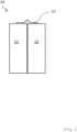
-
1 eine schematische Darstellung einer Batteriezellenanordnung mit einem Werkstück; -
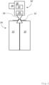
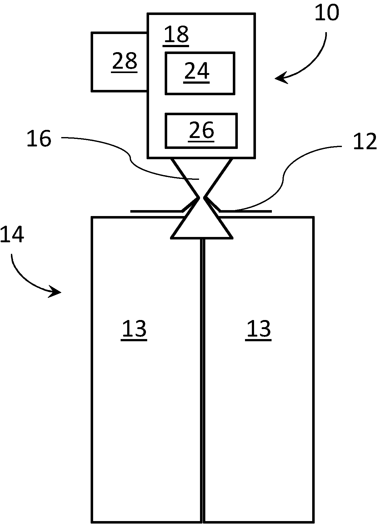
2 eine schematische Darstellung einer Vorrichtung zum Durchtrennen des Werkstücks gemäß1 und -
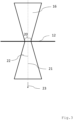
3 eine schematische Darstellung eines mittels der Vorrichtung gemäß2 erzeugten Laserstrahls.
-
1 a schematic representation of a battery cell arrangement with a workpiece; -
2 a schematic representation of a device for cutting the workpiece according to1 and -
3 a schematic representation of a device according to2 generated laser beam.
In der nachfolgenden Beschreibung sowie in den Figuren tragen sich entsprechende Bauteile und Elemente gleiche Bezugszeichen. Der besseren Übersichtlichkeit wegen sind nicht in allen Figuren sämtliche Bezugszeichen wiedergegeben.In the following description and in the figures, corresponding components and elements have the same reference symbols. For the sake of clarity, not all reference symbols are shown in all figures.
Die Vorrichtung 10 umfasst eine Lasereinrichtung 18 zur Erzeugung und/oder Fokussierung des Laserstrahls 16. Die Lasereinrichtung 18 umfasst eine Laserstrahlquelle 24.The
Die Laserstrahlquelle 24 kann als eine (ns-)gepulste Laserstrahlquelle 24 ausgebildet sein. Die Laserstrahlquelle 24 kann eine Leistung in einem Bereich von 70 W bis 1000 W, insbesondere in einem Bereich von 500 W bis 600 W, aufweisen. Die Laserstrahlquelle 24 kann eine Pulsdauer in einem Bereich von 3 ns bis 2000 ns, insbesondere in einem Bereich von 50 ns bis 500 ns, und/oder eine Repetitionsrate in einem Bereich von 1 kHz bis 4 MHz, insbesondere in einem Bereich von 20 kHz bis 80 kHz, aufweisen.The
Die Laserstrahlquelle 24 kann als ein Faserlaser insbesondere ein Single-Mode-Laser, ausgebildet sein. Die Laserstrahlquelle 24 kann dabei eine Leistung in einem Bereich von 0,5 kW bis 5 kW, insbesondere in einem Bereich von 0,5 kW bis 2 kW, aufweisen. Die als Single-Mode-Laser ausgebildete Laserstrahlquelle 24 kann eine Strahlqualität aufweisen, die eine Beugungsmaßzahl M2 von kleiner 1,7 aufweist.The
Die Laserstrahlquelle 24 kann als ein Scheibenlaser, insbesondere ein Multi-Mode-Laser, ausgebildet sein. Die Laserstrahlquelle 24 kann dabei eine Leistung in einem Bereich von 0,5 kW bis 24 kW, insbesondere in einem Bereich von 2 kW bis 8 kW, aufweisen.The
Die Laserstrahlquelle 24 kann als ein Infrarotlaser mit einer Wellenlänge in einem Bereich von 800 nm bis 1200 nm, insbesondere von 1030 nm oder 1070 nm, ausgebildet sein.The
Die Laserstrahlquelle 24 kann als ein Laser mit einer Wellenlänge im sichtbaren Bereich, insbesondere von 515 nm, ausgebildet sein.The
Vorliegend weist die Vorrichtung 10 eine Scanneroptik 26 zum Bewegen des Laserstrahls 16 über das Werkstück 12 auf. Die Scanneroptik 26 ist eingerichtet, um den Laserstrahl 16 mit einer Geschwindigkeit in einem Bereich 10 m/min bis 80 m/min, insbesondere in einem Bereich von 20 m/min bis 60 m/min, über das Werkstück 12 zu bewegen.In the present case, the
Die Scanneroptik 26 kann ein Abbildungsverhältnis in einem Bereich von 1:1 bis 5:1, insbesondere in einem Bereich von 1,5:1 bis 2:1, aufweisen. Mittels der Scanneroptik 26 kann ein Remoteschneiden des Werkstücks 12 umgesetzt werden.The
Die Vorrichtung 10 kann auch eine Festoptik zum fixen Ausrichten des Laserstrahls 16 umfassen. Die Festoptik kann eine Schneiddüse zum Ausrichten und/oder Fokussieren des Laserstrahls 16 umfassen. Die Festoptik kann eine Gaszufuhr zum Zuführen eines Schneidgases (bspw. Stickstoff), insbesondere in den Bereich des fokussierten Laserstrahls 16 auf dem Werkstück 12 umfassen.The
Die Festoptik kann ein Abbildungsverhältnis in einem Bereich von 1:1 bis 5:1, insbesondere in einem Bereich von 1,5:1 bis 2:1, aufweisen.The fixed optics can have an imaging ratio in a range of 1:1 to 5:1, in particular in a range of 1.5:1 to 2:1.
Die Vorrichtung 10 umfasst vorliegend einen optischen Sensor 28. Mittels des optischen Sensors 28 kann die Position des Laserstrahls 16 und/oder des Werkstücks 12 erfasst bzw. kontrolliert werden.The
Der Laserstrahl 16 wird auf dem Werkstück 12 fokussiert. Der fokussierte Laserstrahl hat auf dem Werkstück 12 einen Strahldurchmesser 20. Der Strahldurchmesser 20 kann kleiner gleich 100 µm, insbesondere kleiner gleich 50 µm sein.The
Der Laserstrahl 16 weist vorliegend einen halben Öffnungswinkel 22 der Divergenz von größer gleich 80 mrad auf. Das Strahlparameterprodukt des Laserstrahls 16 liegt dabei in einem Bereich von 0,38 mm*mrad bis 16 mm*mrad.In this case, the
Das Verfahren zum Durchtrennen eines Werkstücks 12, insbesondere eines Zellverbinders einer Batterieanordnung 14, mittels eines Laserstrahls 16 kann anhand der
- Zunächst wird vorliegend mittels der Lasereinrichtung 18
ein Laserstrahl 16 erzeugt und aufdas Werkstück 12 fokussiert. Dabei weist der Laserstrahl 16einen Strahldurchmesser 20, ein Strahlparameterprodukt und/oder einen halben Öffnungswinkel 22, wie oben beschrieben, auf.
- First, a
laser beam 16 is generated by means of thelaser device 18 and focused on theworkpiece 12. Thelaser beam 16 has abeam diameter 20, a beam parameter product and/or ahalf opening angle 22, as described above.
Der Laserstrahl 16 und/oder das Werkstück 12 können bewegt werden, um einen Vorschub (Bewegung) des auf dem Werkstück 12 fokussierten Laserstrahls 16 zu erzeugen. Dabei kann der Vorschub in einem Bereich, wie oben beschrieben, liegen.The
Es kann ein Schneidgas zugeführt werden. Dabei kann das Schneidgases, insbesondere Stickstoff, in den Bereich des fokussierten Laserstrahls 16 auf dem Werkstück 12 zugeführt werden.A cutting gas can be supplied. The cutting gas, in particular nitrogen, can be supplied into the area of the
Es kann die Position des Laserstrahls und/oder des Werkstücks 12 ermittelt werden. Dies kann insbesondere mittels eines optischen Sensors 28 durchgeführt werden.The position of the laser beam and/or the
Zur Durchführung des Verfahrens kann eine in der
Claims (14)
Priority Applications (2)
| Application Number | Priority Date | Filing Date | Title |
|---|---|---|---|
| DE102023121905.7A DE102023121905A1 (en) | 2023-08-16 | 2023-08-16 | Device and method for cutting a workpiece by means of a laser beam |
| PCT/EP2024/070661 WO2025036655A1 (en) | 2023-08-16 | 2024-07-22 | Device and method for cutting through a workpiece by means of a laser beam |
Applications Claiming Priority (1)
| Application Number | Priority Date | Filing Date | Title |
|---|---|---|---|
| DE102023121905.7A DE102023121905A1 (en) | 2023-08-16 | 2023-08-16 | Device and method for cutting a workpiece by means of a laser beam |
Publications (1)
| Publication Number | Publication Date |
|---|---|
| DE102023121905A1 true DE102023121905A1 (en) | 2025-02-20 |
Family
ID=92106456
Family Applications (1)
| Application Number | Title | Priority Date | Filing Date |
|---|---|---|---|
| DE102023121905.7A Pending DE102023121905A1 (en) | 2023-08-16 | 2023-08-16 | Device and method for cutting a workpiece by means of a laser beam |
Country Status (2)
| Country | Link |
|---|---|
| DE (1) | DE102023121905A1 (en) |
| WO (1) | WO2025036655A1 (en) |
Cited By (1)
| Publication number | Priority date | Publication date | Assignee | Title |
|---|---|---|---|---|
| DE102024207809B3 (en) * | 2024-08-15 | 2025-12-11 | Volkswagen Aktiengesellschaft | Method for separating a material bond between a cell connector and a battery cell |
Citations (3)
| Publication number | Priority date | Publication date | Assignee | Title |
|---|---|---|---|---|
| DE102010022298A1 (en) * | 2010-05-27 | 2011-12-01 | Carl Zeiss Meditec Ag | Apparatus and method for cataract surgery |
| US8278591B2 (en) * | 2006-02-03 | 2012-10-02 | L'air Liquide Societe Anonyme Pour L'etude Et L'exploitation Des Procedes Georges Claude | Cutting method using a laser having at least one ytterbium-based fiber, in which at least the power of the laser source, the diameter of the focused beam and the beam quality factor are controlled |
| DE102022100229A1 (en) * | 2022-01-05 | 2023-07-06 | Trumpf Laser- Und Systemtechnik Gmbh | Scanner welding device and method for scanner welding of at least two workpieces |
Family Cites Families (4)
| Publication number | Priority date | Publication date | Assignee | Title |
|---|---|---|---|---|
| DE102012001609B3 (en) * | 2012-01-26 | 2013-02-21 | Precitec Kg | Laser processing head |
| DE102013004095A1 (en) * | 2013-03-11 | 2014-09-11 | Linde Aktiengesellschaft | Method, apparatus and use of a gas composition for laser flame cutting |
| DE102019213417A1 (en) * | 2019-09-04 | 2021-03-04 | Robert Bosch Gmbh | Combined cutting / welding process for Al and Cu materials with heat accumulation from ultra-short laser pulses |
| DE102021119750A1 (en) * | 2021-07-29 | 2023-02-02 | Trumpf Laser- Und Systemtechnik Gmbh | Process for laser cutting of a workpiece, with an intensity minimum extending over the thickness of the workpiece in the center of the intensity profile of the laser beam |
-
2023
- 2023-08-16 DE DE102023121905.7A patent/DE102023121905A1/en active Pending
-
2024
- 2024-07-22 WO PCT/EP2024/070661 patent/WO2025036655A1/en active Pending
Patent Citations (3)
| Publication number | Priority date | Publication date | Assignee | Title |
|---|---|---|---|---|
| US8278591B2 (en) * | 2006-02-03 | 2012-10-02 | L'air Liquide Societe Anonyme Pour L'etude Et L'exploitation Des Procedes Georges Claude | Cutting method using a laser having at least one ytterbium-based fiber, in which at least the power of the laser source, the diameter of the focused beam and the beam quality factor are controlled |
| DE102010022298A1 (en) * | 2010-05-27 | 2011-12-01 | Carl Zeiss Meditec Ag | Apparatus and method for cataract surgery |
| DE102022100229A1 (en) * | 2022-01-05 | 2023-07-06 | Trumpf Laser- Und Systemtechnik Gmbh | Scanner welding device and method for scanner welding of at least two workpieces |
Cited By (1)
| Publication number | Priority date | Publication date | Assignee | Title |
|---|---|---|---|---|
| DE102024207809B3 (en) * | 2024-08-15 | 2025-12-11 | Volkswagen Aktiengesellschaft | Method for separating a material bond between a cell connector and a battery cell |
Also Published As
| Publication number | Publication date |
|---|---|
| WO2025036655A1 (en) | 2025-02-20 |
Similar Documents
| Publication | Publication Date | Title |
|---|---|---|
| DE69027189T2 (en) | Bundle injection into an optical fiber | |
| EP0313594B1 (en) | Joining device and process using laser radiation | |
| EP2456592B1 (en) | Laser machining head and method of compensating for the change in focal position of a laser machining head | |
| EP0414869B1 (en) | Process for quality control of laser beam welding and cutting | |
| EP3838472A1 (en) | Deflection unit with two windows, one optical element and a xy deflection device | |
| DE3902985A1 (en) | DEVICE AND METHOD FOR TREATING WORKPIECES BY MEANS OF A LASER BEAM | |
| EP4034329B1 (en) | Method for producing microstructures on an optical crystal | |
| EP4041487A1 (en) | Alignment device for a bessel beam machining optical system and method | |
| DE102021120648B4 (en) | Optimization of the cutting process when laser cutting a workpiece | |
| DE102016201418A1 (en) | Apparatus and method for thermal processing | |
| EP3917716B1 (en) | Arrangement and method for forming a laser beam | |
| WO2020099421A1 (en) | Method and device for monitoring a welding process for welding glass workpieces | |
| DE102015115270A1 (en) | Method for producing a welded joint in a joint gap and process observation device | |
| EP1656234B1 (en) | Scan head as part of a laser drilling and cutting device | |
| WO2022161724A1 (en) | Laser machining head comprising a chromatic compensation device | |
| DE102023121905A1 (en) | Device and method for cutting a workpiece by means of a laser beam | |
| EP1863612B1 (en) | Method for measuring phase boundaries of a material during machining with a machining beam using additional illumination radiation and an automated image processing algorithm, and associated device | |
| WO2019233944A1 (en) | Device for laser machining workpieces that are difficult to access | |
| DE112023001604T5 (en) | PULSE-ASSISTED LASER-ASSISTED PLASMA IN FLOWING HIGH-PRESSURE FLUIDS | |
| DE102019103211A1 (en) | Method and system for machining a workpiece with a machining steel as well as a device for determining the position of a workpiece to be machined relative to a machining steel and using such a tool | |
| DE102024117484A1 (en) | Arrangement, system and method for generating EUV radiation or for operating nuclear fusion, as well as manufacturing methods for producing microchips or semiconductor intermediates for producing microchips | |
| DE102021109579B4 (en) | METHOD AND APPARATUS FOR MAKING MODIFICATIONS WITH A LASER BEAM IN A MATERIAL WITH A CURVED SURFACE | |
| DE102020121440B4 (en) | Device for generating a defined laser line on a working plane | |
| EP1625771A1 (en) | Method for heating components | |
| DE102021115036A1 (en) | Process for laser processing of a workpiece and associated laser processing system |
Legal Events
| Date | Code | Title | Description |
|---|---|---|---|
| R163 | Identified publications notified | ||
| R081 | Change of applicant/patentee |
Owner name: TRUMPF LASER- UND SYSTEMTECHNIK SE, DE Free format text: FORMER OWNER: TRUMPF LASER- UND SYSTEMTECHNIK GMBH, 71254 DITZINGEN, DE |