DE102010022298A1 - Apparatus and method for cataract surgery - Google Patents
Apparatus and method for cataract surgery Download PDFInfo
- Publication number
- DE102010022298A1 DE102010022298A1 DE102010022298A DE102010022298A DE102010022298A1 DE 102010022298 A1 DE102010022298 A1 DE 102010022298A1 DE 102010022298 A DE102010022298 A DE 102010022298A DE 102010022298 A DE102010022298 A DE 102010022298A DE 102010022298 A1 DE102010022298 A1 DE 102010022298A1
- Authority
- DE
- Germany
- Prior art keywords
- laser
- microscope
- lens
- module
- eye
- Prior art date
- Legal status (The legal status is an assumption and is not a legal conclusion. Google has not performed a legal analysis and makes no representation as to the accuracy of the status listed.)
- Withdrawn
Links
- 208000002177 Cataract Diseases 0.000 title claims abstract description 17
- 238000001356 surgical procedure Methods 0.000 title claims abstract description 13
- 238000000034 method Methods 0.000 title claims description 8
- 230000008878 coupling Effects 0.000 claims abstract description 8
- 238000010168 coupling process Methods 0.000 claims abstract description 8
- 238000005859 coupling reaction Methods 0.000 claims abstract description 8
- 239000011521 glass Substances 0.000 claims description 15
- 238000001514 detection method Methods 0.000 claims description 9
- 230000005484 gravity Effects 0.000 claims description 3
- 230000003044 adaptive effect Effects 0.000 claims description 2
- 238000002560 therapeutic procedure Methods 0.000 claims description 2
- 241000219739 Lens Species 0.000 description 60
- 230000003287 optical effect Effects 0.000 description 7
- 240000004322 Lens culinaris Species 0.000 description 5
- 210000004087 cornea Anatomy 0.000 description 5
- 239000012634 fragment Substances 0.000 description 5
- 230000000694 effects Effects 0.000 description 4
- 210000003128 head Anatomy 0.000 description 4
- 238000012014 optical coherence tomography Methods 0.000 description 4
- 210000001525 retina Anatomy 0.000 description 4
- 201000009310 astigmatism Diseases 0.000 description 2
- 230000008901 benefit Effects 0.000 description 2
- 238000006073 displacement reaction Methods 0.000 description 2
- 239000000284 extract Substances 0.000 description 2
- 238000003384 imaging method Methods 0.000 description 2
- 230000010354 integration Effects 0.000 description 2
- 230000008569 process Effects 0.000 description 2
- 210000001747 pupil Anatomy 0.000 description 2
- 238000002604 ultrasonography Methods 0.000 description 2
- BUHVIAUBTBOHAG-FOYDDCNASA-N (2r,3r,4s,5r)-2-[6-[[2-(3,5-dimethoxyphenyl)-2-(2-methylphenyl)ethyl]amino]purin-9-yl]-5-(hydroxymethyl)oxolane-3,4-diol Chemical compound COC1=CC(OC)=CC(C(CNC=2C=3N=CN(C=3N=CN=2)[C@H]2[C@@H]([C@H](O)[C@@H](CO)O2)O)C=2C(=CC=CC=2)C)=C1 BUHVIAUBTBOHAG-FOYDDCNASA-N 0.000 description 1
- 241001136792 Alle Species 0.000 description 1
- 210000002159 anterior chamber Anatomy 0.000 description 1
- 230000005779 cell damage Effects 0.000 description 1
- 208000037887 cell injury Diseases 0.000 description 1
- 238000010276 construction Methods 0.000 description 1
- 210000000399 corneal endothelial cell Anatomy 0.000 description 1
- 230000006378 damage Effects 0.000 description 1
- 230000003247 decreasing effect Effects 0.000 description 1
- 208000029436 dilated pupil Diseases 0.000 description 1
- 239000000835 fiber Substances 0.000 description 1
- 230000002262 irrigation Effects 0.000 description 1
- 238000003973 irrigation Methods 0.000 description 1
- 238000012634 optical imaging Methods 0.000 description 1
- 230000008520 organization Effects 0.000 description 1
- 230000010287 polarization Effects 0.000 description 1
- 230000002040 relaxant effect Effects 0.000 description 1
- 210000003786 sclera Anatomy 0.000 description 1
- 230000000007 visual effect Effects 0.000 description 1
Images




Classifications
-
- A—HUMAN NECESSITIES
- A61—MEDICAL OR VETERINARY SCIENCE; HYGIENE
- A61F—FILTERS IMPLANTABLE INTO BLOOD VESSELS; PROSTHESES; DEVICES PROVIDING PATENCY TO, OR PREVENTING COLLAPSING OF, TUBULAR STRUCTURES OF THE BODY, e.g. STENTS; ORTHOPAEDIC, NURSING OR CONTRACEPTIVE DEVICES; FOMENTATION; TREATMENT OR PROTECTION OF EYES OR EARS; BANDAGES, DRESSINGS OR ABSORBENT PADS; FIRST-AID KITS
- A61F9/00—Methods or devices for treatment of the eyes; Devices for putting in contact-lenses; Devices to correct squinting; Apparatus to guide the blind; Protective devices for the eyes, carried on the body or in the hand
- A61F9/007—Methods or devices for eye surgery
- A61F9/008—Methods or devices for eye surgery using laser
-
- A—HUMAN NECESSITIES
- A61—MEDICAL OR VETERINARY SCIENCE; HYGIENE
- A61F—FILTERS IMPLANTABLE INTO BLOOD VESSELS; PROSTHESES; DEVICES PROVIDING PATENCY TO, OR PREVENTING COLLAPSING OF, TUBULAR STRUCTURES OF THE BODY, e.g. STENTS; ORTHOPAEDIC, NURSING OR CONTRACEPTIVE DEVICES; FOMENTATION; TREATMENT OR PROTECTION OF EYES OR EARS; BANDAGES, DRESSINGS OR ABSORBENT PADS; FIRST-AID KITS
- A61F9/00—Methods or devices for treatment of the eyes; Devices for putting in contact-lenses; Devices to correct squinting; Apparatus to guide the blind; Protective devices for the eyes, carried on the body or in the hand
- A61F9/007—Methods or devices for eye surgery
- A61F9/00736—Instruments for removal of intra-ocular material or intra-ocular injection, e.g. cataract instruments
-
- A—HUMAN NECESSITIES
- A61—MEDICAL OR VETERINARY SCIENCE; HYGIENE
- A61B—DIAGNOSIS; SURGERY; IDENTIFICATION
- A61B18/00—Surgical instruments, devices or methods for transferring non-mechanical forms of energy to or from the body
- A61B18/18—Surgical instruments, devices or methods for transferring non-mechanical forms of energy to or from the body by applying electromagnetic radiation, e.g. microwaves
- A61B18/20—Surgical instruments, devices or methods for transferring non-mechanical forms of energy to or from the body by applying electromagnetic radiation, e.g. microwaves using laser
- A61B2018/2035—Beam shaping or redirecting; Optical components therefor
- A61B2018/20351—Scanning mechanisms
-
- A—HUMAN NECESSITIES
- A61—MEDICAL OR VETERINARY SCIENCE; HYGIENE
- A61B—DIAGNOSIS; SURGERY; IDENTIFICATION
- A61B18/00—Surgical instruments, devices or methods for transferring non-mechanical forms of energy to or from the body
- A61B18/18—Surgical instruments, devices or methods for transferring non-mechanical forms of energy to or from the body by applying electromagnetic radiation, e.g. microwaves
- A61B18/20—Surgical instruments, devices or methods for transferring non-mechanical forms of energy to or from the body by applying electromagnetic radiation, e.g. microwaves using laser
- A61B2018/2035—Beam shaping or redirecting; Optical components therefor
- A61B2018/20351—Scanning mechanisms
- A61B2018/20355—Special scanning path or conditions, e.g. spiral, raster or providing spot overlap
-
- A—HUMAN NECESSITIES
- A61—MEDICAL OR VETERINARY SCIENCE; HYGIENE
- A61F—FILTERS IMPLANTABLE INTO BLOOD VESSELS; PROSTHESES; DEVICES PROVIDING PATENCY TO, OR PREVENTING COLLAPSING OF, TUBULAR STRUCTURES OF THE BODY, e.g. STENTS; ORTHOPAEDIC, NURSING OR CONTRACEPTIVE DEVICES; FOMENTATION; TREATMENT OR PROTECTION OF EYES OR EARS; BANDAGES, DRESSINGS OR ABSORBENT PADS; FIRST-AID KITS
- A61F9/00—Methods or devices for treatment of the eyes; Devices for putting in contact-lenses; Devices to correct squinting; Apparatus to guide the blind; Protective devices for the eyes, carried on the body or in the hand
- A61F9/007—Methods or devices for eye surgery
- A61F9/008—Methods or devices for eye surgery using laser
- A61F9/009—Auxiliary devices making contact with the eyeball and coupling in laser light, e.g. goniolenses
Landscapes
- Health & Medical Sciences (AREA)
- Ophthalmology & Optometry (AREA)
- Life Sciences & Earth Sciences (AREA)
- Animal Behavior & Ethology (AREA)
- Engineering & Computer Science (AREA)
- Biomedical Technology (AREA)
- Heart & Thoracic Surgery (AREA)
- Vascular Medicine (AREA)
- Nuclear Medicine, Radiotherapy & Molecular Imaging (AREA)
- Surgery (AREA)
- General Health & Medical Sciences (AREA)
- Public Health (AREA)
- Veterinary Medicine (AREA)
- Physics & Mathematics (AREA)
- Optics & Photonics (AREA)
- Laser Surgery Devices (AREA)
- Microscoopes, Condenser (AREA)
Abstract
Die Erfindung betrifft Verbesserungen bzgl. der Durchführung und des Ergebnisses von Kataraktoperationen durch ein Laser-System. Insbesondere betrifft sie eine Vorrichtung zur Kataraktchirurgie, welche ein Operations- oder Stereomikroskop und eine Laserquelle aufweist, bei der ein Modul bestehend aus Laser-Einkoppel/Umlenk-, -Scan-Einheit und Fokussiereinheit am Operationsmikroskop oder Stereomikroskop befestigbar ist, bei der zumindest eines dieser Einheiten zwischen Operationsmikroskop und Auge wahlweise eingebracht werden kann und bei der die Fokussiereinheit einen Fokus-Tiefen-Bereich größer als 1 mm überstreichen kann.The invention relates to improvements with regard to the implementation and the result of cataract operations by a laser system. In particular, it relates to a device for cataract surgery, which has a surgical or stereo microscope and a laser source, in which a module consisting of a laser coupling / deflection, scanning unit and focusing unit can be attached to the surgical microscope or stereo microscope, in which at least one of these Units can optionally be inserted between the surgical microscope and eye and in which the focusing unit can cover a focus-depth range greater than 1 mm.
Description
Anwendungsgebiet:Field of use:
Die Erfindung betrifft Verbesserungen bzgl. der Durchführung und des Ergebnisses von Kataraktoperationen durch ein Laser-System.The invention relates to improvements in the performance and outcome of cataract surgery by a laser system.
Stand der Technik:State of the art:
Bei einer Kataraktoperation wird derzeit typischerweise am weitgetropften (d. h. durch Medikamente erweiterte Pupille) und lokalnarkotisierten Auge folgendes durchgeführt:
- • Etwa 1,5–3 mm breiter, manuell gesetzter Schnitt in die Hornhaut mit einem Skalpell um für alles folgende einen Zugang zur Vorderkammer des Auges zu schaffen und
- • Etwa 3–6 mm durchmessender, kreisförmiger manuell gesetzten Schnitt in den vorderen Kapselsack mit einem speziellen Skalpell; Entfernen des Kapselsackssegments um Zugang zur Linse zu schaffen.
- • Zerschneiden und anschließendes weiteres Zerteilen der Linse bzw. der Linsenbruchstücke, kombiniert mit dem Absaugen der Bruchstücke mit einem Ultraschallgeräte-/Spül-Sauggerät unter Verwendung verschiedener Ultraschallenergien und Spülgeschwindigkeiten bzw. Saugdrücken (Phacoemulsifikation).
- • Einsetzen der Intraokularlinse in den Kapselsack.
- • Approximately 1.5-3 mm wide, manually placed incision in the cornea with a scalpel to provide access to the anterior chamber of the eye for all to follow and
- • Approximately 3-6 mm diameter, circular, manually placed incision in the anterior capsular bag with a special scalpel; Remove the capsular bag segment to gain access to the lens.
- • Cutting and then further splitting the lens or lens fragments, combined with aspirating the fragments with an ultrasonic device / irrigation suction device using various ultrasonic energies and rinsing speeds or suction pressures (phacoemulsification).
- • Insert the intraocular lens into the capsular bag.
Alternativ oder ergänzend zu den bisherigen Instrumenten (Operationsmikroskop, Phacoemulsifikationseinrichtung, auch als Phaco-Maschine bezeichnet) wird ein Femtosekunden-Lasersystem (fs-Laser) verwendet für
- • den Hornhaut-Schnitt,
- • den Kapselsack-Schnitt,
- • Zerschneiden und weiteres Zerteilen der Linse,
- • Setzen von ggf. erwünschten oder notwendigen relaxierenden Schnitten in die Hornhaut (um Astigmatismus zu kompensieren).
- The corneal cut,
- • the capsular bag cut,
- Cutting and further splitting the lens,
- • Setting any desired or necessary relaxing cuts in the cornea (to compensate for astigmatism).
Durch die Verwendung eines Schnittlasers lassen sich genauer positionierte, von ihrem Ausmaß genauer definierte Schnitte durchführen. Durch die zusätzliche Implementierung einer Navigation z. B. mittels optischer Kohärenztomographie in Verbindung mit dem Lasersystem lassen sich die Prozesse des Schneidens und Teilens automatisieren ohne daß erhaltenswertes Gewebe z. B. der hintere Kapselsack verletzt wird. Dadurch werden die erheblichen Risiken der manuellen/visuellen Schnittführung durch den Operateur vermieden und auch weniger operationserfahrene Ärzte erzielen eine geringere Komplikationsrate und bessere refraktive Ergebnisse.The use of a cut laser makes it possible to carry out more precisely positioned cuts, which are more precisely defined by their extent. Due to the additional implementation of a navigation z. B. by means of optical coherence tomography in conjunction with the laser system, the processes of cutting and splitting can be automated without worth preserving tissue z. B. the rear capsular bag is injured. This avoids the significant risks of manual / visual incision by the surgeon, and less experienced physicians achieve a lower complication rate and better refractive outcomes.
In
Ein anderes Lasersystem ist in
Nachteilig erweisen sich die lange Scanzeit durch Objektivscan, was beim Kornea-Flap-Schneiden akzeptabel ist, da nur ein Schnitt gesetzt werden muss, sowie die Verwendung eines teueren fs-Lasers. Ferner ist bei diesem System prinzipbedingt die Fokustiefe nicht tief genug um Schnitte in der Linse durchführen zu können und es fehlt eine für Linseschnitte notwendige 3D-Navigation. Außerdem ist das Gesamtgerät für die typische OP-Situation (Operationsmikroskop, Phacomaschine) zu voluminös.A disadvantage is the long scan time due to lens scanning, which is acceptable for cornea flap cutting, since only one cut must be made, and the use of an expensive fs laser. Furthermore, in this system, the depth of focus is not deep enough to perform cuts in the lens and there is a lack of necessary for lens cuts 3D navigation. In addition, the overall device for the typical surgical situation (surgical microscope, phaco machine) is too bulky.
Beschreibung der Erfindung:Description of the invention:
Aufgabe der Erfindung ist es, ein Lasersystem für die Kataraktchirurgie zu schaffen, das kompakter baut und daher leichter in die bestehende Systemumgebung integriert werden kann, kostengünstiger ist und trotzdem die Anforderungen der Laser-Linsen-Chirurgie, wie große Apertur (um die Retina nicht zu belasten und um ausreichend kleinen Fokus zu erzielen), hohe Scangeschwindigkeit (um innerhalb von etwa 1 Minute alle notwendigen Schnitte, insbesondere zum Zerkleinern der Linse, durchführen zu können) erfüllt.The object of the invention is to provide a laser system for cataract surgery, which builds more compact and therefore easier in the existing System environment can be integrated, is more cost-effective, and yet the requirements of laser lens surgery, such as large aperture (to not strain the retina and to achieve sufficiently small focus), high scanning speed (within about 1 minute, all the necessary cuts, in particular for crushing the lens to perform) met.
In einer ersten Variante (A1) wird diese Aufgabe gelöst durch ein Laser- und Navigationssystem als Zusatzmodul für ein Operationsmikroskop, bestehend aus
- 1. Einem fs-Laser oder einem ps-Laser.
- 2. a) einem am Mikroskop schwenkbar gehaltenes und definiert zwischen Mikroskopobjektiv und Kontaktglas bzw. Auge positionierbares, zurüstbares Modul mit hochaperturigem Objektiv mit großem Fokusverstellbereich b) oder alternativ ein am Mikroskop fixes und definiert zwischen Mikroskopobjektiv und Kontaktglas bzw. Auge positionierbares, zurüstbares Modul mit hochaperturigem Objektiv, wobei das Modul zusätzlich eine Linse zur teilweisen Kompensation des Objektiv-Effektes bei Durchsicht durch das Objektiv aufweist.
- 3. Ggf. einem Kontaktglas (so daß das Gesamtsystem aus Objektiv und ggf. dem Kontaktglas eine NA > 0,2 aufweist).
- 4. Einer Umlenk/Ablenk-Einheit, die den Laser in das Objektiv einkoppelt, als Bestandteil des Moduls. Im Fall 2.b) ist dies als dichrotischer Spiegel (im sichtbaren Bereich transmitiv, im Bereich der Laserwellenlänge reflektiv) ausgelegt.
- 5. Zwei spiegelnd ausgelegten schnellen Scannern oder einem schnellen 2-Achsenscanner, die den Laserstrahl in x/y-Richtung ablenken oder einem Scanner und Elementen zur Strahlrotation als Bestandteil des Moduls.
- 6. Ggf. einer Detektionseinheit, die das vom Auge reflektierte/gestreute Laserlicht detektiert und daraus Navigationsdaten für die online-Steuerung und die Vororientierung des Schnittmusters gewinnt.
- 7. Eine Laserzuführung, bevorzugt einem Lichtleiter oder Freistrahlgelenkarm, welches den Laserstrahl von der Laserquelle dem Modul zuführt.
- 1. An FS laser or a PS laser.
- 2. a) a microscope position pivotally held and defined between the microscope objective and contact lens or eye positionable, zuüstbares module with hochaperturigem lens with large Fokusverstellbereich b) or alternatively fixed to the microscope and defined between microscope objective and contact lens or eye positionable, equipped with hochaperturigem lens, wherein the module additionally has a lens for partial compensation of the lens effect when viewed through the lens.
- 3. If necessary a contact glass (so that the total system of lens and possibly the contact glass has a NA> 0.2).
- 4. A deflection / deflection unit that couples the laser into the lens as part of the module. In case 2.b) this is designed as a dichroic mirror (in the visible range transmitiv, in the range of the laser wavelength reflective).
- 5. Two mirror-type fast scanners or a fast 2-axis scanner that deflects the laser beam in the x / y direction or a scanner and beam rotation elements as part of the module.
- 6. If necessary a detection unit which detects the laser light reflected / scattered by the eye and extracts therefrom navigation data for on-line control and pre-orientation of the pattern.
- 7. A laser feed, preferably a light guide or free beam articulated arm, which feeds the laser beam from the laser source to the module.
Diese Variante ist besonders geeignet für eine hohe Anzahl von Schnitten bei der Zerkleinerung der Linse.This variant is particularly suitable for a high number of cuts in the comminution of the lens.
In einer alternativen Variante (A2) wird diese Aufgabe gelöst durch ein Laser- und Navigationssystem mit Zusatzmodulen für ein Operationsmikroskop, bestehend aus
- 1. Einem fs-Laser oder einem ps-Laser.
- 2. einem am Mikroskop schwenkbar gehaltenes und definiert zwischen Mikroskopobjektiv und Kontaktglas bzw. Auge positionierbares, zurüstbares Modul mit hochaperturigem Objektiv mit großem Fokusverstellbereich
- 3. Ggf. einem Kontaktglas (so daß das Gesamtsystem aus Objektiv und ggf. dem Kontaktglas eine NA > 0,2 aufweist).
- 4. Einer Einheit, die den Laser in das Mikroskop einkoppelt, wobei die Mikroskop-Optik den Laser in das verfahrbare hochaperaturartige Objektiv einkoppelt
- 5. Einem Strahlscanner, bestehend z. B. aus zwei spiegelnd ausgelegten schnellen Scanner oder einem schnellen 2-Achsenscanner, die den Laserstrahl in x/y-Richtung ablenken oder einem Scanner und Elementen zur Strahlrotation als Bestandteil des zurüstbaren Objektiv-Moduls oder als separates Modul in der Lasterstrahlzuführung zum Operationsmikroskop.
- 6. Ggf. einer Detektionseinheit, die das vom Auge reflektierte/gestreute Laserlicht detektiert und daraus Navigationsdaten für die online-Steuerung und die Vororientierung des Schnittmusters gewinnt.
- 1. An FS laser or a PS laser.
- 2. a microscope-pivotally held and defined between the microscope objective and contact lens or eye positionable, zuüstbares module with hochaperturigem lens with a large Fokusverstellbereich
- 3. If necessary a contact glass (so that the total system of lens and possibly the contact glass has a NA> 0.2).
- 4. A unit that couples the laser into the microscope, with the microscope optics coupling the laser into the movable, highly auronic lens
- 5. A beam scanner, consisting of z. B. from two mirror-designed fast scanner or a fast 2-axis scanner, which deflect the laser beam in the x / y direction or a scanner and elements for beam rotation as part of the composable lens module or as a separate module in the load beam to the surgical microscope.
- 6. If necessary a detection unit which detects the laser light reflected / scattered by the eye and extracts therefrom navigation data for on-line control and pre-orientation of the pattern.
Diese Variante ist ebenfalls besonders geeignet ist für eine hohe Anzahl von Schnitten bei der Zerkleinerung der Linse, und wobei das Mikroskop bereits eine Einkopplung für einen Laser enthält z. B. auch über die optische Schnittstelle einer Mitbeobachtungsoptik.This variant is also particularly suitable for a high number of cuts in the comminution of the lens, and wherein the microscope already contains a coupling for a laser z. B. also via the optical interface of a co-observation optics.
In einer weiteren alternativen Variante (B1) wird diese Aufgabe gelöst durch ein Laser- und Navigationssystem als Zusatzmodul für ein Operationsmikroskop, bestehend aus
- 1. Einem fs-Laser oder einem ps-Laser.
- 2. Einem am Mikroskop schwenkbar gehaltenes und definiert zwischen Mikroskopobjektiv und Kontaktglas bzw Auge positionierbares, zurüstbares Modul mit in x/y/z-Richtung innerhalb des Moduls verfahrbarem hochaperturigem Objektiv.
- 3. Ggf. einem Kontaktglas (so daß das Gesamtsystem aus Objektiv und ggf. dem Kontaktglas eine NA > 0,2 aufweist).
- 4. Einer Einheit, die den Laser in das Objektiv einkoppelt, als Bestandteil des Moduls.
- 5. Einer 3-Achsen-Objektiv-Positioniereinheit, realisiert z. B. über Piezoantriebe oder Schritt- oder Servomotoren
- 6. Ggf. einer Detektionseinheit, die das vom Auge reflektierte Laserlicht detektiert und daraus Navigationsdaten für die online-Steuerung und die Vororientierung des Schnittmusters gewinnt.
- 7. Eine Laserzuführung, bevorzugt einem Lichtleiter oder Freistrahlgelenkarm, welches den Laserstrahl von der Quelle dem Modul zuführt.
- 1. An FS laser or a PS laser.
- 2. A positionable on the microscope and pivotally defined between microscope objective and contact lens or eye positionable, zuüstbares module with movable in x / y / z direction within the module hochaperturigem lens.
- 3. If necessary a contact glass (so that the total system of lens and possibly the contact glass has a NA> 0.2).
- 4. A unit that couples the laser into the lens as part of the module.
- 5. A 3-axis lens positioning unit, realized z. B. via piezo drives or stepper or servo motors
- 6. If necessary a detection unit which detects the laser light reflected by the eye and derives therefrom navigation data for on-line control and pre-orientation of the pattern.
- 7. A laser feeder, preferably a light guide or free beam articulated arm, which feeds the laser beam from the source to the module.
Diese Variante ist insbesondere geeignet für eine geringere Anzahl von Schnitten, z. B. wenn nur ein Kreuzschnitt der Linse oder auch nur zähe, dichte Kataraktbereiche geschnitten werden sollen.This variant is particularly suitable for a smaller number of cuts, z. B. if only a cross-section of the lens or even tough, dense cataract areas to be cut.
In einer weiteren Variante (B2) wird diese Aufgabe gelöst durch ein Laser- und Navigationssystem mit Zusatzmodulen für ein Operationsmikroskop, bestehend aus
- 1. Einem fs-Laser oder einem ps-Laser.
- 2. Einem am Mikroskop schwenkbar gehaltenes und definiert zwischen Mikroskopobjektiv und Kontaktglas bzw Auge positionierbares, zurüstbares Modul mit in x/y/z-Richtung innerhalb des Moduls verfahrbarem, hochaperturigem Objektiv.
- 3. Ggf. einem Kontaktglas (sodaß das Gesamtsystem aus Objektiv und ggf. dem Kontaktglas eine NA > 0,2 aufweist).
- 4. Einer Einheit, die den Laser in das Mikroskop einkoppelt, wobei die Mikroskop-Optik den Laser in das verfahrbare hochaperturige Objektiv einkoppelt.
- 5. Einer 3-Achsen/3D-Objektiv-Positioniereinheit, realisiert z. B. über Piezoantriebe oder Schritt- oder Servomotoren. Alternativ zum x/y bzw. x-Scan kann das Objektiv auch in x/y-Achsen bzw. in x-Achse motorisch gekippt werden.
- 6. Ggf. einer Detektionseinheit als Zusatz zum Mikroskop oder dem zurüstbaren Modul, die das vom Auge reflektierte Laserlicht detektiert und daraus Navigationsdaten für die online-Steuerung und die Vororientierung des Schnittmusters gewinnt.
- 7. Eine Laserzuführung, bevorzugt einem Lichtleiter oder Freistrahlgelenkarm, welches den Laserstrahl von der Quelle dem Mikroskop zuführt.
- 1. An FS laser or a PS laser.
- 2. A microscope-pivotally held and defined between the microscope objective and the contact lens or eye positionable, zuüstbares module with in x / y / z direction within the module movable, hochaperturigem lens.
- 3. If necessary a contact glass (so that the total system of lens and possibly the contact glass has a NA> 0.2).
- 4. A unit that couples the laser into the microscope, with the microscope optics coupling the laser into the movable high-aperture objective.
- 5. A 3-axis / 3D lens positioning unit, realized z. B. via piezo drives or stepper or servo motors. As an alternative to the x / y or x-scan, the objective can also be tilted by motor in x / y axes or in x-axis.
- 6. If necessary a detection unit as an add-on to the microscope or the modulatable module, which detects the laser light reflected by the eye and from this obtains navigation data for the online control and the pre-orientation of the pattern.
- 7. A laser feeder, preferably a light guide or free beam articulated arm, which feeds the laser beam from the source to the microscope.
Diese Variante ist insbesondere geeignet für eine geringere Anzahl von Schnitten, z. B. wenn nur ein Kreuzschnitt der Linse oder auch nur die zähen, dichten Kataraktbereiche geschnitten werden sollen und wenn das Operations-Mikroskop schon eine Einkopplung für einen Laser enthält, z. B. auch über die optische Schnittstelle der Mitbeobachtungsoptik.This variant is particularly suitable for a smaller number of cuts, z. B. if only a cross-section of the lens or even the tough, dense cataract areas should be cut and if the surgical microscope already contains a coupling for a laser, z. B. also via the optical interface of the co-observation optics.
Dabei weist der fs-Laser bevorzugt eine Pulslänge zwischen 100 fs und 1000 fs bei einer Pulsenergie von 0,10 μJ bis 10,00 μJ und Repetitionsfreuenzen von 50 kHz bis 500 kHz auf. Durch diese Pulslängen und Energie wird erreicht, daß der Laser in einem Gewebevolumen von etwa 5 Mikrometer Durchmesser eine Dampf/Plasma-Blase erzeugen kann, wobei nur geringe Effekte außerhalb dieses Volumens induziert werden. Durch die hohe Repititionsfrequenz in Verbindung mit den schnellen Scanner wird erreicht, daß innerhalb einer Minute mindestens 8 vertikale/oder radiale und 2 horizontale Schnitte in der Linse, deren Dicke zwischen 3–6 mm beträgt, erzeugt werden können.In this case, the fs laser preferably has a pulse length between 100 fs and 1000 fs at a pulse energy of 0.10 μJ to 10.00 μJ and repetition frequencies of 50 kHz to 500 kHz. By these pulse lengths and energy it is achieved that the laser can generate a vapor / plasma bubble in a tissue volume of about 5 micrometers in diameter, whereby only small effects are induced outside this volume. Due to the high repetition frequency in connection with the fast scanners it is achieved that within one minute at least 8 vertical / or radial and 2 horizontal cuts in the lens, whose thickness is between 3-6 mm, can be generated.
Der ps-Laser weist bevorzugt eine Pulslänge zwischen 1 ps und 20 ps bei einer Pulsenergie von 1 μJ bis 200 μJ und Repetitionsfreuenzen von 25 kHz bis 150 kHz auf. Durch diese Pulslängen und Energie wird erreicht, daß der Laser in einem Gewebevolumen von etwa 10–15 Mikrometer Durchmesser eine Dampf/Plasma-Blase erzeugt. Im Gegensatz zum fs-Laser wirkt sich jedoch der ps-Laser aufgrund der thermischen Effekte und der Druckeffekte auf ein größeres Volumen aus. Dies ist aber weitgehend unkritisch, da die Linse bei der Kataraktoperation sowieso ganz entfernt wird und die Schnitte an der Korea und im Kapselsack nicht einer für eine optische Abbildung notwendigen Präzision (z. B. bzgl. Rauhigkeit, Formgenauigkeit) genügen müssen. Allerdings sollten Pulsdauer und Energie nicht wesentlich über den angegebenen Werten liegen, da sonst die Gefahr einer Verletzung der Korneaendothelzellen durch Druckspitzen oder des nach dem Eingriff im Auge noch verbleibenden vorderen Kapselsackssegments signifikant erhöht wird.The ps laser preferably has a pulse length between 1 ps and 20 ps at a pulse energy of 1 μJ to 200 μJ and repetition frequencies of 25 kHz to 150 kHz. By these pulse lengths and energy it is achieved that the laser generates a vapor / plasma bubble in a tissue volume of about 10-15 micrometers in diameter. Unlike the fs laser, however, the ps laser has a larger volume due to thermal effects and pressure effects. However, this is largely uncritical since the lens is completely removed during the cataract operation anyway, and the cuts on the Korea and in the capsular bag do not have to satisfy a precision necessary for an optical imaging (eg with respect to roughness, dimensional accuracy). However, pulse duration and energy should not be significantly above the values given, as otherwise the risk of corneal endothelial cell injury being significantly increased by pressure peaks or the anterior capsular segment remaining after the procedure in the eye.
Für beide Laser gilt, daß bei kleineren Linsen oder wenn die Schnitte nur in den dichten Bereichen der Linse erfolgen oder die Schnitte nur dazu dienen, den initialen Ultraschall-Kreuzschnitt zu ersetzen auch weniger Schnitte als die obigen etwa 8 angegebenen sinnvoll sind, sodaß die Repetitionsfrequenz oder die Gesamtzeit für die Schnitte erniedrigt werden kannFor both lasers it is true that with smaller lenses or when the cuts are made only in the dense areas of the lens or the cuts only serve to replace the initial ultrasonic cross cut also less cuts than the above indicated about 8 are meaningful, so the repetition frequency or the total time for the cuts can be decreased
Bei dichtem oder zähem Katarakt oder Kataraktbereichen – erkennbar z. B. über die Streulichtdaten der Detektoreinheit – kann die Anzahl der Schnitte insgesamt jedoch auch höher liegen oder auch nur in den dichten oder zähen Kataraktbereichen die Schnittdichte lokal erhöht werden. Insbesondere kann der Abstand zwischen 2 Schnittflächen auf die typische Geometrie/Dimension des Saugkopfeingangs oder darunter reduziert werden.In dense or tough cataract or cataract areas - recognizable z. B. on the scattered light data of the detector unit - the total number of cuts, however, may also be higher or even in the dense or tough cataract areas, the density of cut locally be increased. In particular, the distance between two cut surfaces may be reduced to the typical geometry / dimension of the suction head entrance or below.
Dadurch müssen die Bruchstücke der Linse nicht durch einen später erfolgenden Phacoschritt noch viel weiter zerkleinert werden. Dadurch kann die Ultraschallenergie erheblich verringert oder idealerweise ganz auf den Einsatz von Ultraschall verzichtet werden.As a result, the fragments of the lens need not be comminuted much further by a later phaco step. As a result, the ultrasound energy can be considerably reduced or, ideally, the use of ultrasound completely dispensed with.
Zur Erfindung gehört weiterhin ein Verfahren zur lasergestützten Augenchirurgie, bei der die Laserstrahlquelle flexibel mit einem Scan- und Fokussiermodul verbunden ist, welches mechanisch ausbalanciert im direkten Kontakt mit dem Auge zur intraokularen Navigation und Therapie eingesetzt wird.The invention further includes a method for laser-assisted eye surgery in which the laser beam source is flexibly connected to a scanning and focusing module, which is used mechanically balanced in direct contact with the eye for intraocular navigation and therapy.
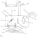
Im folgenden wird die Erfindung an Hand der Zeichnungen näher erläutert.In the following the invention will be explained in more detail with reference to the drawings.
Es zeigenShow it
In
Das Objektiv
Als Scanner
Weiter alternativ kann auch ein in 2 Achsen bewegliche MEMS-Scanner eingesetzt werden. In der in
Es ist jedoch auch möglich, daß das Objektiv
Das Modul
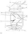
In Variante A2 wird der Laser zuerst in das Mikroskop eingekoppelt und dieses leitet den Laser in das Objektiv
In der Variante B1 und B2 beinhaltet das zu einem Operations- oder Stereomikroskop
In
Als Detektionseinheit dient ein hier nicht dargestellter konfokaler Detektor oder ein Flächendetektor. Das konfokale Signal dient zur Bestimmung der Grenzflächen wie es in der
Zusammen mit dem nichtkonfokalen Anteil läßt sich eine Streuintensität bestimmen, und sich anhand dieser Streuintensität der Laser in einem oder auch mehreren der Parameter Pulsenergie,- Dauer, Repetitionsfrequenz und/oder Scangeschwindigkeit steuern. Die Auskopplung des reflektierten Lichts kann ggf. über eine Kombination aus Wellenplatte und Polarisationsteiler erfolgen. Als Detektionseinheit kommt auch eine OCT-Einheit in Betracht.Together with the non-confocal component, it is possible to determine a scattering intensity and to use this scattered intensity of the lasers to control one or more of the parameters pulse energy, duration, repetition frequency and / or scan speed. If necessary, the coupling-out of the reflected light can take place via a combination of wave plate and polarization splitter. As detection unit is also an OCT unit into consideration.
Um das Gesamtmodul
Ferner ist in das Modul
Um die Integration zu fördern und die Bedienung zu erleichtern, ist eine – in dem Modul integrierte oder extern zur Verfügung gestellte – Kontroller/Steuereinheit vorgesehen, welche den folgenden Arbeitsablauf unterstützt:
- 1. Der Operateur setzt ggf. (a) das Kontaktglas auf das weitgetropfte, narkotisierte Auge auf oder alternativ (b) das Kontaktglas wird auf das Zusatzmodul aufgesetzt.
- 2. Der Operateur bewegt den Mikroskopkopf über das Kontaktglas oder Auge. Über eine Zentrierung die ihm eingespiegelt wird oder die er anhand eines Monitorbildes erkennt, kann er die Position lateral und bzgl. der Entfernung (Größe der Zentrierung) zum Kontaktglas bzw. Auge einstellen. Bei geeigneter Entfernung wird das Modul manuell oder automatisch eingeschwenkt; Um im Fall (a) den Kontakt zwischen Modul und Kontaktglas herzustellen wird der Mikroskopkopf zum Auge gefahren und/oder der Druck-Weggeber verlängert, bis der notwendige Kontakt und Anpressdruck mit dem Auge besteht. Während dessen oder danach wird der Ansaugdruck appliziert. Um in Fall (b) den Kontakt zwischen Modul/Kontaktglas und Auge herzustellen können ebenfalls das Mikroskop oder der Druck-Weggeber zu in (a) analoger Weise eingesetzt werden.
- 3. Das Lasersystem scannt bei niedriger Energie den Augenraum in 3D ab. Über die Detektionseinheit werden Landmarken bestimmt und das vorgesehene Schneidmuster an der realen 3D Struktur orientiert. Ggf. wird der Schnittabstand entsprechend der Kataraktdichte gewonnen aus den Detektordaten so angepaßt, das die verbleibenden Bruchstücke bei geringer Ultraschall-Energie zerstört und eingesaugt werden können.
- 4. Der Laser zerschneidet die Linse von posterior nach anterior anhand der orientierten Schneidmusters unter online-Navigations-/Laserparameter-kontrolle.
- 5. Der Laser zerschneidet den Kapselsack
- 6. Der Laser macht den Hornhautschnitt, ggf. nach vorhergehender wiederholter 3D-Orientierung.
- 7. Anpress- und Ansaugdruck werden zurückgenommen. Mikroskop und/oder der Druck-Weggeber werden vom Auge weggezogen. Das Modul wird manuell oder automatisch ausgeschwenkt. Das Kontaktglas wird manuell entfernt.
- 8. ggf. werden Information über die Lage der Schnitte, insbesondere in der Hornhaut und im Kapselsack am Monitorbild angezeigt oder ins OPMI eingespiegelt
- 9. Operateur setzt manuell seine Katarakt-Operation fort.
- 1. If necessary, the surgeon applies (a) the contact lens to the well-dripped, anesthetized eye or alternatively (b) the contact lens is placed on the additional module.
- 2. The surgeon moves the microscope head over the contact lens or eye. He can adjust the position laterally and with respect to the distance (size of the centering) to the contact lens or eye via a centering which is reflected to him or which he recognizes on the basis of a monitor image. If properly removed, the module is swiveled in manually or automatically; In case (a) to establish contact between the module and the contact lens, the microscope head is moved to the eye and / or the pressure transducer is extended until the necessary contact and contact pressure with the eye exists. During or after this, the suction pressure is applied. In case (b) to establish contact between the module / contact lens and the eye, the microscope or the pressure transducer can also be used analogously to (a).
- 3. The laser system scans the eye space in 3D at low energy. Landmarks are determined via the detection unit and the intended cutting pattern is oriented to the real 3D structure. Possibly. is the intersection distance obtained in accordance with the cataract density obtained from the detector data adapted so that the remaining fragments can be destroyed and sucked in at low ultrasonic energy.
- 4. The laser cuts the lens from posterior to anterior using the oriented cutting pattern under online navigation / laser parameter control.
- 5. The laser cuts the capsular bag
- 6. The laser makes the corneal section, possibly after previous repeated 3D orientation.
- 7. Contact pressure and suction pressure are withdrawn. Microscope and / or the pressure transducer are pulled away from the eye. The module is swiveled out manually or automatically. The contact glass is removed manually.
- 8. If necessary, information about the position of the cuts, in particular in the cornea and in the capsular bag, are displayed on the monitor image or reflected in the OPMI
- 9. Surgeon manually continues his cataract surgery.
Die Erfindung ist nicht an die dargestellten Ausführungsbeispiele gebunden, fachmännische Weiterentwicklungen führen nicht aus dem Schutzbereich.The invention is not bound to the illustrated embodiments, expert advances do not lead from the scope.
ZITATE ENTHALTEN IN DER BESCHREIBUNG QUOTES INCLUDE IN THE DESCRIPTION
Diese Liste der vom Anmelder aufgeführten Dokumente wurde automatisiert erzeugt und ist ausschließlich zur besseren Information des Lesers aufgenommen. Die Liste ist nicht Bestandteil der deutschen Patent- bzw. Gebrauchsmusteranmeldung. Das DPMA übernimmt keinerlei Haftung für etwaige Fehler oder Auslassungen.This list of the documents listed by the applicant has been generated automatically and is included solely for the better information of the reader. The list is not part of the German patent or utility model application. The DPMA assumes no liability for any errors or omissions.
Zitierte PatentliteraturCited patent literature
- WO 09039302 [0005] WO09039302 [0005]
- US 7621637 [0006] US 7621637 [0006]
- DE 10323422 [0042] DE 10323422 [0042]
Claims (15)
Priority Applications (4)
| Application Number | Priority Date | Filing Date | Title |
|---|---|---|---|
| DE102010022298A DE102010022298A1 (en) | 2010-05-27 | 2010-05-27 | Apparatus and method for cataract surgery |
| EP11721723.2A EP2575712B1 (en) | 2010-05-27 | 2011-05-26 | Device for cataract surgery |
| US13/700,396 US20130072917A1 (en) | 2010-05-27 | 2011-05-26 | Device and method for cataract surgery |
| PCT/EP2011/002608 WO2011147570A1 (en) | 2010-05-27 | 2011-05-26 | Device and method for cataract surgery |
Applications Claiming Priority (1)
| Application Number | Priority Date | Filing Date | Title |
|---|---|---|---|
| DE102010022298A DE102010022298A1 (en) | 2010-05-27 | 2010-05-27 | Apparatus and method for cataract surgery |
Publications (1)
| Publication Number | Publication Date |
|---|---|
| DE102010022298A1 true DE102010022298A1 (en) | 2011-12-01 |
Family
ID=44924582
Family Applications (1)
| Application Number | Title | Priority Date | Filing Date |
|---|---|---|---|
| DE102010022298A Withdrawn DE102010022298A1 (en) | 2010-05-27 | 2010-05-27 | Apparatus and method for cataract surgery |
Country Status (4)
| Country | Link |
|---|---|
| US (1) | US20130072917A1 (en) |
| EP (1) | EP2575712B1 (en) |
| DE (1) | DE102010022298A1 (en) |
| WO (1) | WO2011147570A1 (en) |
Cited By (11)
| Publication number | Priority date | Publication date | Assignee | Title |
|---|---|---|---|---|
| DE102011088038A1 (en) * | 2011-12-08 | 2013-06-13 | Leica Microsystems (Schweiz) Ag | Surgical microscope system for ophthalmology and associated detection unit |
| DE102013106920A1 (en) | 2012-08-17 | 2014-05-22 | Carl Zeiss Meditec Ag | Device system and method for phacoemulsification |
| EP2633842A3 (en) * | 2012-02-28 | 2014-07-09 | Ziemer Ophthalmic Systems AG | Ophthalmological patient interface device |
| DE102014108596B3 (en) * | 2014-06-18 | 2015-10-22 | Carl Zeiss Ag | Lens and optical device |
| WO2016156760A1 (en) * | 2015-04-01 | 2016-10-06 | Alphanov Centre Technologique Optique Et Lasers | Ophthalmic surgical apparatus |
| DE102016107225A1 (en) | 2016-04-19 | 2017-10-19 | Carl Zeiss Meditec Ag | Method and system for eye observation and therapy, in particular apparatus for laser-assisted cataract surgery |
| DE102017107926A1 (en) | 2016-07-18 | 2018-01-18 | Carl Zeiss Meditec Ag | System for eye observation and therapy, in particular apparatus for laser-assisted eye surgery |
| EP3329885A1 (en) * | 2016-12-05 | 2018-06-06 | Ziemer Ophthalmic Systems AG | Ophthalmic patient interface device |
| US10722399B2 (en) | 2014-10-17 | 2020-07-28 | Carl Zeiss Meditec Ag | Systems for short pulse laser eye surgery |
| DE102021210661A1 (en) | 2021-09-24 | 2023-03-30 | Carl Zeiss Meditec Ag | Method and arrangement for recalibrating the focus of an ophthalmological system for intraocular laser treatment |
| DE102023121905A1 (en) * | 2023-08-16 | 2025-02-20 | TRUMPF Laser- und Systemtechnik SE | Device and method for cutting a workpiece by means of a laser beam |
Families Citing this family (31)
| Publication number | Priority date | Publication date | Assignee | Title |
|---|---|---|---|---|
| JP2014522284A (en) * | 2011-06-09 | 2014-09-04 | クリストファー ホルヴァト | Laser transmission system for ophthalmic surgery |
| US8986290B2 (en) | 2011-10-06 | 2015-03-24 | Douglas Patton | Systems and methods for combined femto-phaco cataract surgery |
| TWI588560B (en) | 2012-04-05 | 2017-06-21 | 布萊恩荷登視覺協會 | Lens, device, method and system for refractive error |
| US9629523B2 (en) | 2012-06-27 | 2017-04-25 | Camplex, Inc. | Binocular viewing assembly for a surgical visualization system |
| US9642606B2 (en) | 2012-06-27 | 2017-05-09 | Camplex, Inc. | Surgical visualization system |
| US9201250B2 (en) | 2012-10-17 | 2015-12-01 | Brien Holden Vision Institute | Lenses, devices, methods and systems for refractive error |
| WO2014058973A1 (en) * | 2012-10-09 | 2014-04-17 | Douglas Patton | Systems & methods for combined femto-phaco cataract surgery |
| SG11201502115RA (en) | 2012-10-17 | 2015-05-28 | Holden Brien Vision Inst | Lenses, devices, methods and systems for refractive error |
| WO2014163897A1 (en) | 2013-03-13 | 2014-10-09 | Optimedica Corporation | Free floating patient interface for laser surgery system |
| EP3434235B1 (en) * | 2013-03-13 | 2023-04-26 | AMO Development, LLC | Laser eye surgery system |
| WO2014189969A1 (en) | 2013-05-21 | 2014-11-27 | Camplex, Inc. | Surgical visualization systems |
| US10881286B2 (en) | 2013-09-20 | 2021-01-05 | Camplex, Inc. | Medical apparatus for use with a surgical tubular retractor |
| WO2015042460A1 (en) | 2013-09-20 | 2015-03-26 | Camplex, Inc. | Surgical visualization systems and displays |
| EP3203292B1 (en) * | 2014-10-03 | 2023-02-22 | Sony Group Corporation | Medical-use stereoscopic microscope optical system and medical-use observation device |
| WO2016090336A1 (en) | 2014-12-05 | 2016-06-09 | Camplex, Inc. | Surgical visualization systems and displays |
| HK1250471A1 (en) | 2015-03-25 | 2018-12-21 | 卡姆普勒克斯公司 | Surgical visualization systems and displays |
| WO2017091704A1 (en) | 2015-11-25 | 2017-06-01 | Camplex, Inc. | Surgical visualization systems and displays |
| US20170188825A1 (en) * | 2015-12-30 | 2017-07-06 | Novartis Ag | Extended depth of focus contact lens for vitreoretinal surgery |
| EP3439595B1 (en) * | 2016-04-05 | 2024-10-23 | AMO Development, LLC | Eye docking for laser eye surgery |
| US10549382B2 (en) | 2016-05-04 | 2020-02-04 | Purdue Research Foundation | Laser-assisted micromachining systems and methods |
| US12350198B2 (en) | 2016-09-28 | 2025-07-08 | Lensar, Inc. | Systems for laser eye surgery |
| US10918455B2 (en) | 2017-05-08 | 2021-02-16 | Camplex, Inc. | Variable light source |
| US11215814B2 (en) * | 2018-08-24 | 2022-01-04 | Amo Development, Llc | Detection of optical surface of patient interface for ophthalmic laser applications using a non-confocal configuration |
| US12465436B2 (en) | 2018-10-19 | 2025-11-11 | Lensar, Inc. | Cloud based system cataract treatment database and algorithm system |
| US11980573B2 (en) | 2019-12-05 | 2024-05-14 | Johnson & Johnson Surgical Vision, Inc. | Eye examination apparatus |
| JP2023509439A (en) | 2020-01-03 | 2023-03-08 | レンサー インク | Combined laser-integrated system for phacoemulsification |
| US12551102B2 (en) * | 2020-01-15 | 2026-02-17 | Duke University | Systems and methods for peripheral retinal optical coherence tomography |
| WO2022079560A1 (en) * | 2020-10-16 | 2022-04-21 | Amo Development, Llc | Laser focal spot size measurement using a built-in camera for an ophthalmic laser system |
| US12207799B2 (en) | 2020-12-28 | 2025-01-28 | Johnson & Johnson Surgical Vision, Inc. | Highly bendable camera for eye surgery |
| EP4415666A1 (en) * | 2021-10-14 | 2024-08-21 | Appasamy Associates Pvt Ltd | Single and/or dual (532 and/or 577) nm laser delivery system attached to an ophthalmic microscope |
| CN114176768B (en) * | 2021-12-10 | 2024-01-30 | 北京市汉华环球科技发展有限责任公司 | Method and device for detecting deflection timeout of vibrating mirror in lattice laser therapeutic instrument |
Citations (6)
| Publication number | Priority date | Publication date | Assignee | Title |
|---|---|---|---|---|
| DE10100859A1 (en) * | 2001-01-11 | 2002-08-14 | Zeiss Carl Jena Gmbh | Medical laser therapy device |
| DE10323422A1 (en) | 2002-08-23 | 2004-04-15 | Carl Zeiss Meditec Ag | Device for measuring optical penetration in tissue during laser surgery, has detector that generates detection signal indicating spatial dimension and/or position of optical penetration in tissue |
| US20040243111A1 (en) * | 2003-06-02 | 2004-12-02 | Mark Bendett | Method and apparatus for precision working of material |
| WO2009039302A2 (en) | 2007-09-18 | 2009-03-26 | Lensx Lasers, Inc. | Methods and apparatus for integrated cataract surgery |
| US20090149841A1 (en) * | 2007-09-10 | 2009-06-11 | Kurtz Ronald M | Effective Laser Photodisruptive Surgery in a Gravity Field |
| US7621637B2 (en) * | 2005-06-09 | 2009-11-24 | Sie Ag Surgical Instrument Engineering | Ophthalmologic device for breaking down eye tissue |
Family Cites Families (14)
| Publication number | Priority date | Publication date | Assignee | Title |
|---|---|---|---|---|
| US4638801A (en) * | 1983-07-06 | 1987-01-27 | Lasers For Medicine | Laser ophthalmic surgical system |
| JPS6294153A (en) * | 1985-10-18 | 1987-04-30 | 興和株式会社 | Laser beam coagulation apparatus |
| US4887592A (en) * | 1987-06-02 | 1989-12-19 | Hanspeter Loertscher | Cornea laser-cutting apparatus |
| DE3724282A1 (en) * | 1987-07-22 | 1989-02-02 | Rodenstock Instr | Supplementary optical system for surgical microscopes and slit lamps for laser treatment |
| DE3831141A1 (en) * | 1988-09-13 | 1990-03-22 | Zeiss Carl Fa | METHOD AND DEVICE FOR MICROSURGERY ON EYE BY LASER RADIATION |
| US20020049450A1 (en) * | 1996-03-21 | 2002-04-25 | Second Sight Laser Technologies, Inc. | Correction of presbyopia, other refractive errors and cataract retardation |
| DE19852574A1 (en) * | 1998-11-06 | 2000-05-11 | Aesculap Meditec Gmbh | Medical instrument for phacoemulsification |
| DE19940712A1 (en) * | 1999-08-26 | 2001-03-01 | Aesculap Meditec Gmbh | Method and device for treating opacities and / or hardening of an unopened eye |
| DE10025843A1 (en) * | 2000-05-23 | 2001-12-13 | Zeiss Carl Jena Gmbh | Ophthalmological unit adaptor for laser treatment allows adjustment and exchange |
| WO2007103349A2 (en) * | 2006-03-07 | 2007-09-13 | The Trustees Of Princeton University | Devices, methods and compositions for presbyopia correction using ultrashort pulse lasers |
| JP5766123B2 (en) * | 2008-12-31 | 2015-08-19 | アイ オプティマ リミテッド | Apparatus and method for laser-based deep scleral ablation |
| EP2395955B1 (en) * | 2009-02-09 | 2018-08-01 | AMO Development, LLC | System for intrastromal refractive correction |
| DE102009012873B4 (en) * | 2009-03-12 | 2021-08-19 | Carl Zeiss Meditec Ag | Ophthalmic laser system and control unit |
| US9504608B2 (en) * | 2009-07-29 | 2016-11-29 | Alcon Lensx, Inc. | Optical system with movable lens for ophthalmic surgical laser |
-
2010
- 2010-05-27 DE DE102010022298A patent/DE102010022298A1/en not_active Withdrawn
-
2011
- 2011-05-26 EP EP11721723.2A patent/EP2575712B1/en active Active
- 2011-05-26 WO PCT/EP2011/002608 patent/WO2011147570A1/en not_active Ceased
- 2011-05-26 US US13/700,396 patent/US20130072917A1/en not_active Abandoned
Patent Citations (6)
| Publication number | Priority date | Publication date | Assignee | Title |
|---|---|---|---|---|
| DE10100859A1 (en) * | 2001-01-11 | 2002-08-14 | Zeiss Carl Jena Gmbh | Medical laser therapy device |
| DE10323422A1 (en) | 2002-08-23 | 2004-04-15 | Carl Zeiss Meditec Ag | Device for measuring optical penetration in tissue during laser surgery, has detector that generates detection signal indicating spatial dimension and/or position of optical penetration in tissue |
| US20040243111A1 (en) * | 2003-06-02 | 2004-12-02 | Mark Bendett | Method and apparatus for precision working of material |
| US7621637B2 (en) * | 2005-06-09 | 2009-11-24 | Sie Ag Surgical Instrument Engineering | Ophthalmologic device for breaking down eye tissue |
| US20090149841A1 (en) * | 2007-09-10 | 2009-06-11 | Kurtz Ronald M | Effective Laser Photodisruptive Surgery in a Gravity Field |
| WO2009039302A2 (en) | 2007-09-18 | 2009-03-26 | Lensx Lasers, Inc. | Methods and apparatus for integrated cataract surgery |
Cited By (16)
| Publication number | Priority date | Publication date | Assignee | Title |
|---|---|---|---|---|
| DE102011088038B4 (en) * | 2011-12-08 | 2019-10-10 | Leica Microsystems (Schweiz) Ag | Surgical microscope system for ophthalmology and associated detection unit |
| DE102011088038A1 (en) * | 2011-12-08 | 2013-06-13 | Leica Microsystems (Schweiz) Ag | Surgical microscope system for ophthalmology and associated detection unit |
| EP2633842A3 (en) * | 2012-02-28 | 2014-07-09 | Ziemer Ophthalmic Systems AG | Ophthalmological patient interface device |
| US8784406B2 (en) | 2012-02-28 | 2014-07-22 | Ziemer Ophthalmic Systems Ag | Ophthalmological patient interface device |
| US9358157B2 (en) | 2012-02-28 | 2016-06-07 | Ziemer Ophthalmic Systems Ag | Apparatus for treating eye tissue with laser pulses |
| DE102013106920A1 (en) | 2012-08-17 | 2014-05-22 | Carl Zeiss Meditec Ag | Device system and method for phacoemulsification |
| DE102014108596B3 (en) * | 2014-06-18 | 2015-10-22 | Carl Zeiss Ag | Lens and optical device |
| US10722399B2 (en) | 2014-10-17 | 2020-07-28 | Carl Zeiss Meditec Ag | Systems for short pulse laser eye surgery |
| US12070424B2 (en) | 2014-10-17 | 2024-08-27 | Carl Zeiss Meditec Ag | Systems and methods for short pulse laser eye surgery |
| FR3034310A1 (en) * | 2015-04-01 | 2016-10-07 | Alphanov Centre Tech Optique Et Lasers | APPARATUS FOR OPHTHALMIC SURGERY |
| WO2016156760A1 (en) * | 2015-04-01 | 2016-10-06 | Alphanov Centre Technologique Optique Et Lasers | Ophthalmic surgical apparatus |
| DE102016107225A1 (en) | 2016-04-19 | 2017-10-19 | Carl Zeiss Meditec Ag | Method and system for eye observation and therapy, in particular apparatus for laser-assisted cataract surgery |
| DE102017107926A1 (en) | 2016-07-18 | 2018-01-18 | Carl Zeiss Meditec Ag | System for eye observation and therapy, in particular apparatus for laser-assisted eye surgery |
| EP3329885A1 (en) * | 2016-12-05 | 2018-06-06 | Ziemer Ophthalmic Systems AG | Ophthalmic patient interface device |
| DE102021210661A1 (en) | 2021-09-24 | 2023-03-30 | Carl Zeiss Meditec Ag | Method and arrangement for recalibrating the focus of an ophthalmological system for intraocular laser treatment |
| DE102023121905A1 (en) * | 2023-08-16 | 2025-02-20 | TRUMPF Laser- und Systemtechnik SE | Device and method for cutting a workpiece by means of a laser beam |
Also Published As
| Publication number | Publication date |
|---|---|
| EP2575712B1 (en) | 2018-10-31 |
| US20130072917A1 (en) | 2013-03-21 |
| EP2575712A1 (en) | 2013-04-10 |
| WO2011147570A1 (en) | 2011-12-01 |
| WO2011147570A8 (en) | 2012-03-08 |
Similar Documents
| Publication | Publication Date | Title |
|---|---|---|
| DE102010022298A1 (en) | Apparatus and method for cataract surgery | |
| DE112008002448B4 (en) | Effective laser photodisruptive surgery in a gravitational field | |
| EP1627617B1 (en) | Ophthalmological device for ablation of eye tissue | |
| EP2069099B1 (en) | Device and method for processing material using a transparent contact element | |
| EP2231084B1 (en) | Laser correction of vision conditions on the natural eye lens | |
| DE112008002511T5 (en) | Methods and devices for integrated cataract surgery | |
| DE112009001166T5 (en) | Photodisruptive laser treatment of the crystalline lens | |
| DE102019007148A1 (en) | Arrangement for OCT-supported laser vitreolysis | |
| DE10334108B4 (en) | Apparatus for forming a closed, curved cut surface | |
| DE102011109058A1 (en) | "Ophthalmic Laser Device and Method for the Prevention and Treatment of After-Star" | |
| DE112008002405T5 (en) | Photodisruptive treatment of crystalline lenses | |
| DE102011103181A1 (en) | Device and method for vitreous surgery | |
| DE102013106920A1 (en) | Device system and method for phacoemulsification | |
| DE112008002380T5 (en) | Laser-induced protective shield in laser surgery | |
| DE102010055966B4 (en) | Device for processing material of a workpiece and method for calibrating such a device | |
| DE102009012873A1 (en) | Ophthalmic laser system | |
| DE10237945A1 (en) | Laser-based device for non-mechanical, three-dimensional trepanation in corneal transplants | |
| EP2440164A1 (en) | Device for laser-surgical ophthalmology | |
| DE102015205696A1 (en) | Ophthalmic laser therapy device | |
| WO2010060443A1 (en) | System for ophthalmology or dermatology | |
| DE102017207529A1 (en) | Aftercare for eye surgery refraction correction | |
| DE102011116368A1 (en) | Apparatus and method for extracapsular surgical cataract treatment | |
| DE102004009212B4 (en) | Contact element for laser processing and laser processing device | |
| WO2010115441A1 (en) | Optical imaging system, particularly in a laser surgical device for ophthalmology | |
| WO2017182360A1 (en) | Method and system for eye observation and eye therapy, in particular apparatus for laser-assisted cataract surgery |
Legal Events
| Date | Code | Title | Description |
|---|---|---|---|
| R083 | Amendment of/additions to inventor(s) | ||
| R012 | Request for examination validly filed | ||
| R120 | Application withdrawn or ip right abandoned |