DE102021125900A1 - Connection device for connecting an electrical conductor - Google Patents
Connection device for connecting an electrical conductor Download PDFInfo
- Publication number
- DE102021125900A1 DE102021125900A1 DE102021125900.2A DE102021125900A DE102021125900A1 DE 102021125900 A1 DE102021125900 A1 DE 102021125900A1 DE 102021125900 A DE102021125900 A DE 102021125900A DE 102021125900 A1 DE102021125900 A1 DE 102021125900A1
- Authority
- DE
- Germany
- Prior art keywords
- slide
- housing
- connection device
- clamping
- lever
- Prior art date
- Legal status (The legal status is an assumption and is not a legal conclusion. Google has not performed a legal analysis and makes no representation as to the accuracy of the status listed.)
- Pending
Links
- 239000004020 conductor Substances 0.000 title claims abstract description 52
- 230000033001 locomotion Effects 0.000 description 7
- 238000006073 displacement reaction Methods 0.000 description 5
- 238000003780 insertion Methods 0.000 description 5
- 230000037431 insertion Effects 0.000 description 5
- 239000000463 material Substances 0.000 description 2
- BUHVIAUBTBOHAG-FOYDDCNASA-N (2r,3r,4s,5r)-2-[6-[[2-(3,5-dimethoxyphenyl)-2-(2-methylphenyl)ethyl]amino]purin-9-yl]-5-(hydroxymethyl)oxolane-3,4-diol Chemical compound COC1=CC(OC)=CC(C(CNC=2C=3N=CN(C=3N=CN=2)[C@H]2[C@@H]([C@H](O)[C@@H](CO)O2)O)C=2C(=CC=CC=2)C)=C1 BUHVIAUBTBOHAG-FOYDDCNASA-N 0.000 description 1
- 229910000639 Spring steel Inorganic materials 0.000 description 1
- 238000005452 bending Methods 0.000 description 1
- 230000005540 biological transmission Effects 0.000 description 1
- 238000007373 indentation Methods 0.000 description 1
- 239000011810 insulating material Substances 0.000 description 1
Images


Classifications
-
- H—ELECTRICITY
- H01—ELECTRIC ELEMENTS
- H01R—ELECTRICALLY-CONDUCTIVE CONNECTIONS; STRUCTURAL ASSOCIATIONS OF A PLURALITY OF MUTUALLY-INSULATED ELECTRICAL CONNECTING ELEMENTS; COUPLING DEVICES; CURRENT COLLECTORS
- H01R4/00—Electrically-conductive connections between two or more conductive members in direct contact, i.e. touching one another; Means for effecting or maintaining such contact; Electrically-conductive connections having two or more spaced connecting locations for conductors and using contact members penetrating insulation
- H01R4/28—Clamped connections, spring connections
- H01R4/48—Clamped connections, spring connections utilising a spring, clip, or other resilient member
- H01R4/4809—Clamped connections, spring connections utilising a spring, clip, or other resilient member using a leaf spring to bias the conductor toward the busbar
- H01R4/4828—Spring-activating arrangements mounted on or integrally formed with the spring housing
-
- H—ELECTRICITY
- H01—ELECTRIC ELEMENTS
- H01R—ELECTRICALLY-CONDUCTIVE CONNECTIONS; STRUCTURAL ASSOCIATIONS OF A PLURALITY OF MUTUALLY-INSULATED ELECTRICAL CONNECTING ELEMENTS; COUPLING DEVICES; CURRENT COLLECTORS
- H01R4/00—Electrically-conductive connections between two or more conductive members in direct contact, i.e. touching one another; Means for effecting or maintaining such contact; Electrically-conductive connections having two or more spaced connecting locations for conductors and using contact members penetrating insulation
- H01R4/28—Clamped connections, spring connections
- H01R4/48—Clamped connections, spring connections utilising a spring, clip, or other resilient member
- H01R4/4809—Clamped connections, spring connections utilising a spring, clip, or other resilient member using a leaf spring to bias the conductor toward the busbar
- H01R4/48185—Clamped connections, spring connections utilising a spring, clip, or other resilient member using a leaf spring to bias the conductor toward the busbar adapted for axial insertion of a wire end
- H01R4/4819—Clamped connections, spring connections utilising a spring, clip, or other resilient member using a leaf spring to bias the conductor toward the busbar adapted for axial insertion of a wire end the spring shape allowing insertion of the conductor end when the spring is unbiased
- H01R4/4821—Single-blade spring
-
- H—ELECTRICITY
- H01—ELECTRIC ELEMENTS
- H01R—ELECTRICALLY-CONDUCTIVE CONNECTIONS; STRUCTURAL ASSOCIATIONS OF A PLURALITY OF MUTUALLY-INSULATED ELECTRICAL CONNECTING ELEMENTS; COUPLING DEVICES; CURRENT COLLECTORS
- H01R4/00—Electrically-conductive connections between two or more conductive members in direct contact, i.e. touching one another; Means for effecting or maintaining such contact; Electrically-conductive connections having two or more spaced connecting locations for conductors and using contact members penetrating insulation
- H01R4/28—Clamped connections, spring connections
- H01R4/48—Clamped connections, spring connections utilising a spring, clip, or other resilient member
- H01R4/4809—Clamped connections, spring connections utilising a spring, clip, or other resilient member using a leaf spring to bias the conductor toward the busbar
- H01R4/4828—Spring-activating arrangements mounted on or integrally formed with the spring housing
- H01R4/4835—Mechanically bistable arrangements, e.g. locked by the housing when the spring is biased
Landscapes
- Details Of Connecting Devices For Male And Female Coupling (AREA)
Abstract
Eine Anschlussvorrichtung (1) zum Anschließen eines elektrischen Leiters (2) umfasst ein Gehäuse (10), einen Strombalken (11), ein Klemmelement (12) mit einem Klemmabschnitt (120), der aus einer Klemmstellung, in welcher ein elektrischer Leiter (2) gegen den Strombalken (11) klemmbar ist, in eine Freigabestellung überführbar ist, und einen Schieber (13), der zum Überführen des Klemmabschnitts (120) aus der Klemmstellung in die Freigabestellung verschiebbar am Gehäuse (10) gelagert ist. Dabei ist ein an einer gehäusefesten Lagerstelle (106) um eine Drehachse (D) schwenkbar gelagerter Hebel (14) vorgesehen, mittels dem der Schieber (13) relativ zum Gehäuse (10) verschiebbar ist.A connecting device (1) for connecting an electrical conductor (2) comprises a housing (10), a current bar (11), a clamping element (12) with a clamping section (120) which, from a clamping position in which an electrical conductor (2nd ) can be clamped against the current bar (11), can be transferred into a release position, and a slide (13) which is displaceably mounted on the housing (10) for transferring the clamping section (120) from the clamped position into the release position. A lever (14) pivoted about an axis of rotation (D) at a bearing point (106) fixed to the housing is provided, by means of which the slide (13) can be displaced relative to the housing (10).
Description
Die Erfindung betrifft eine Anschlussvorrichtung zum Anschließen eines elektrischen Leiters nach dem Oberbegriff des Anspruchs 1.The invention relates to a connection device for connecting an electrical conductor according to the preamble of claim 1.
Elektrische Anschlussvorrichtungen unterschiedlicher Bauformen sind aus der Praxis bekannt. Bei einem Schraubanschluss beispielsweise wird eine elektrische Leitung mit einem abisolierten Leiterende in eine Stecköffnung eingesteckt und sodann durch Verschrauben klemmend an dem Schraubanschluss festgelegt. Bei einer Federkraftklemme wird demgegenüber ein elektrischer Leiter in eine Stecköffnung eingesteckt und kommt mit dem Schenkel einer Feder in Anlage, wobei die Feder derart auf den elektrischen Leiter einwirkt, dass der elektrische Leiter mechanisch arretiert und zudem elektrisch zum Beispiel mit einem Strombalken kontaktiert ist.Electrical connection devices of different designs are known from practice. In the case of a screw connection, for example, an electrical line with a stripped conductor end is inserted into a plug-in opening and then fixed in a clamping manner on the screw connection by screwing. In the case of a spring-loaded terminal, on the other hand, an electrical conductor is inserted into a plug-in opening and comes into contact with the leg of a spring, the spring acting on the electrical conductor in such a way that the electrical conductor is mechanically locked and is also electrically contacted, for example with a current bar.
Bei solchen Anschlussvorrichtungen ist wünschenswert, ein einfaches Anschließen eines elektrischen Leiters zu ermöglichen. Vorteilhaft kann hierbei sein, dass beim Einstecken eines elektrischen Leiters die Anschlussvorrichtung selbsttätig schließt, also z.B. ein Klemmelement selbsttätig aus einer Freigabestellung in eine Klemmstellung überführt wird, um sicher und zuverlässig mit dem in die Stecköffnung des Gehäuses eingesteckten elektrischen Leiter zu kontaktieren. Ein Kontaktieren, insbesondere ein selbsttätiges Auslösen, soll hierbei oftmals nicht nur bei einem vergleichsweise starren elektrischen Leiter, beispielsweise bei einer an einen elektrischen Leiter angeordneten Aderendhülse oder einem Draht, möglich sein, sondern auch bei einem elektrischen Leiter, der mit vergleichsweise geringer Steckkraft in die Stecköffnung des Gehäuses eingesteckt wird, z.B. in Form eines Litzenleiters.In such connection devices, it is desirable to enable easy connection of an electrical conductor. It can be advantageous here that when an electrical conductor is plugged in, the connection device closes automatically, e.g. a clamping element is automatically transferred from a release position to a clamping position in order to make safe and reliable contact with the electrical conductor inserted into the plug-in opening of the housing. Contacting, in particular automatic triggering, should often not only be possible with a comparatively rigid electrical conductor, for example with a ferrule arranged on an electrical conductor or a wire, but also with an electrical conductor that can be inserted into the plug-in opening of the housing, e.g. in the form of a stranded conductor.
In der
Aufgabe der vorliegenden Erfindung ist es, eine möglichst leicht handhabbare Anschlussvorrichtung zum Anschließen eines elektrischen Leiters zur Verfügung zu stellen.The object of the present invention is to provide a connection device for connecting an electrical conductor that is as easy as possible to handle.
Diese Aufgabe wird durch einen Gegenstand mit den Merkmalen des Anspruchs 1 gelöst.This object is solved by an object with the features of claim 1.
Demnach wird eine Anschlussvorrichtung zum Anschließen eines elektrischen Leiters bereitgestellt, umfassend ein Gehäuse, einen Strombalken, ein Klemmelement mit einem Klemmabschnitt, der aus einer Klemmstellung, in welcher ein elektrischer Leiter gegen den Strombalken klemmbar ist, in eine Freigabestellung überführbar ist, und einen Schieber, der zum Überführen des Klemmabschnitts aus der Klemmstellung in die Freigabestellung verschiebbar am Gehäuse gelagert ist. Dabei ist ein an einer gehäusefesten Lagerstelle um eine Drehachse relativ zum Gehäuse schwenkbar gelagerter Hebel vorgesehen, mittels dem der Schieber relativ zum Gehäuse verschiebbar ist.Accordingly, a connecting device for connecting an electrical conductor is provided, comprising a housing, a current bar, a clamping element with a clamping section which can be transferred from a clamping position, in which an electrical conductor can be clamped against the current bar, into a release position, and a slide, which is slidably mounted on the housing for transferring the clamping section from the clamping position into the release position. A lever is provided at a bearing point fixed to the housing and is pivotable about an axis of rotation relative to the housing, by means of which the slide can be displaced relative to the housing.
Das erlaubt eine klar definierte Schwenkbewegung des Hebels mit einer besonders geringen Neigung der Bauteile zu einem Verklemmen, wodurch die Anschlussvorrichtung besonders leicht handhabbar ist.This allows a clearly defined pivoting movement of the lever with a particularly low tendency of the components to jam, as a result of which the connection device is particularly easy to handle.
Das Gehäuse kann eine Kulisse umfassen, mittels welcher der Schieber verschiebbar gelagert ist. Das erlaubt eine besonders klar definierte Bewegung des Schiebers. Der Schieber berührt z. B. den Klemmabschnitt. Der Schieber ist beispielsweise so angeordnet, dass eine Verschiebung des Schiebers relativ zum Gehäuse den Klemmabschnitt aus der Klemmstellung in die Freigabestellung drängt. Der Klemmabschnitt ist z.B. federelastisch in die Klemmstellung vorgespannt.The housing can include a connecting link, by means of which the slide is mounted in a displaceable manner. This allows a particularly clearly defined movement of the slider. The slider touches z. B. the clamping section. The slide is arranged, for example, in such a way that a displacement of the slide relative to the housing forces the clamping section out of the clamping position into the release position. The clamping section is e.g. resiliently prestressed into the clamping position.
In einer Weiterbildung ist die Kulisse an einer Stelle erweitert. Beispielsweise umfasst die Kulisse entlang ihres Verlaufs einen ersten Abschnitt und einen im Vergleich zum ersten Abschnitt senkrecht zum Verlauf breiteren zweiten Abschnitt. Der breitere zweite Abschnitt ist beispielsweise an einem Ende der Kulisse ausgebildet. Der breitere zweite Abschnitt ermöglicht eine Bewegung des Schiebers senkrecht zu einer Verschieberichtung entlang der Kulisse.In a development, the backdrop is expanded at one point. For example, along its course, the connecting link comprises a first section and a second section, which is wider perpendicularly to the course than the first section. The wider second section is formed at one end of the link, for example. The wider second section allows the slider to move perpendicularly to a direction of displacement along the connecting link.
Optional weist der Schieber einen Pin auf, der mit der Kulisse in Eingriff steht, insbesondere in der Kulisse geführt ist. So kann der Verschiebeweg des Schiebers genau vorgegeben werden.Optionally, the slider has a pin that engages with the backdrop, in particular is guided in the backdrop. In this way, the displacement path of the slider can be specified precisely.
Optional umfasst das Gehäuse eine weitere Kulisse, mittels welcher z.B. der Schieber relativ zum Gehäuse verschiebbar gelagert ist. Dabei kann vorgesehen sein, dass die zwei Kulissen unterschiedlich geformt und/oder ausgerichtet sind. Das ermöglicht eine kombinierte Translations- und Rotationsbewegung. Beispielsweise ist eine der Kulissen zumindest abschnittsweise geradlinig und/oder eine der Kulissen zumindest abschnittsweise gebogen.Optionally, the housing includes a further connecting link, by means of which, for example, the slide is mounted so that it can be moved relative to the housing. It can be provided that the two links are shaped and/or aligned differently. This enables a combined translational and rotational movement. For example, one of the links is straight at least in sections and/or one of the links is curved at least in sections.
Der Schieber kann eine Rastkante aufweisen, die z.B. mit einer Kante des Gehäuses verrastbar ist. Diese Verrastung ist beispielsweise lösbar, indem der Pin des Schiebers im verbreiterten Abschnitt der Kulisse in eine von der Haupterstreckungsrichtung der Kulisse verschiedenen Richtung verlagert wird.The slide can have a latching edge which can be latched, for example, with an edge of the housing. This latching can be released, for example, by displacing the pin of the slide in the broadened section of the link in a direction different from the main direction of extension of the link.
Der Schieber weist optional eine Auslösefläche auf, die durch einen durch eine Stecköffnung des Gehäuses eingeführten elektrischen Leiter berührbar ist. Indem der Schieber selbst eine Auslösefläche bereitstellt, ist es möglich, die Anschlussvorrichtung mit besonders wenigen Teilen und damit besonders einfach aufzubauen.The slide optionally has a release surface that can be touched by an electrical conductor that is inserted through a plug-in opening in the housing is. Because the slide itself provides a triggering surface, it is possible to construct the connecting device with particularly few parts and therefore particularly easily.
In einer Weiterbildung ist der Schieber durch einen durch den in die Stecköffnung eingeführten elektrischen Leiter ausgeübten Druck auf die Auslösefläche relativ zum Gehäuse verlagerbar, und zwar insbesondere derart, dass die Rastkante des Schiebers dabei außer Eingriff mit der Kante des Gehäuses gebracht und von der Kante gelöst wird. So wird bei einem einfachen Aufbau eine intuitive Bedienung ermöglicht.In a further development, the slide can be displaced relative to the housing by pressure exerted on the triggering surface by the electrical conductor inserted into the plug-in opening, in particular in such a way that the latching edge of the slide is disengaged from the edge of the housing and released from the edge becomes. This enables intuitive operation with a simple structure.
Der Hebel weist z.B. einen Hebelarm mit einem Betätigungsbereich auf, der mit einer Fläche des Schiebers zusammenwirkt, beispielsweise mit einer konkaven Fläche. Das erlaubt infolge der Schwenkbewegung des Hebels um die gehäusefeste Lagerstelle eine gleichzeitige Verschiebung des Schiebers relativ zum Gehäuse sowie einen seitwärts gerichteten Druck auf den hinteren Bereich des Schiebers. Hierdurch kann der Schieber einfach und sicher in einen verrastenden Eingriff mit der Kante des Gehäuses gebracht werden.For example, the lever has a lever arm with an operating area which cooperates with a surface of the slide, for example a concave surface. As a result of the pivoting movement of the lever about the bearing point fixed to the housing, this allows a simultaneous displacement of the slide relative to the housing and a sideways pressure on the rear area of the slide. This allows the slider to be easily and securely snapped into engagement with the edge of the housing.
Der Hebel kann ferner einen Hebelarm aufweisen, der durch einen Benutzer betätigbar ist, beispielsweise manuell und/oder mittels eines Werkzeugs. Dies ermöglicht eine einfache und intuitive Bedienung.The lever can also have a lever arm that can be actuated by a user, for example manually and/or by means of a tool. This enables simple and intuitive operation.
Der Hebel kann so ausgestaltet sein, dass die Drehachse zwischen den beiden Hebelarmen angeordnet ist. Zum Beispiel gehen beide Hebelarme von der Drehachse aus. Die Hebelarme können auf gegenüberliegenden Seiten der Drehachse angeordnet sein. Das erlaubt eine kompakte Außenform und eine gute Ergonomie.The lever can be designed in such a way that the axis of rotation is arranged between the two lever arms. For example, both lever arms emanate from the axis of rotation. The lever arms can be arranged on opposite sides of the axis of rotation. This allows for a compact exterior shape and good ergonomics.
Der Schieber ist beispielsweise zwischen dem Hebel und dem Klemmelement angeordnet, zumindest der überwiegende Teil des Schiebers. Das ermöglicht eine effiziente Kraftübertragung. Bei einer Betätigung übt der Hebel beispielsweise einen Druck auf den Schieber aus und/oder der Schieber übt einen Druck auf den Klemmabschnitt aus.The slide is arranged, for example, between the lever and the clamping element, at least the major part of the slide. This enables efficient power transmission. When it is actuated, the lever exerts pressure on the slide, for example, and/or the slide exerts pressure on the clamping section.
Die Lagerstelle kann in Form einer (physischen) Achse ausgebildet sein. Der Hebel weist z.B. eine Aufnahme auf, in welcher die Achse aufgenommen ist. Das ermöglicht einen einfachen Zusammenbau und eine robuste Lagerung des Hebels.The bearing point can be in the form of a (physical) axis. The lever has, for example, a seat in which the axle is seated. This enables easy assembly and robust storage of the lever.
Optional ist das Klemmelement in Form einer Feder ausgebildet, insbesondere in Form einer Schenkelfeder mit zwei federelastisch zueinander auslenkbaren Schenkeln. Der Klemmabschnitt kann federelastisch in die Klemmstellung vorgespannt sein. Dabei kann vorgesehen sein, dass der Klemmabschnitt durch einen der Schenkel ausgebildet ist und/oder dass ein ortsfest zum Gehäuse abgestützter Halteabschnitt durch einen (den anderen) der Schenkel ausgebildet ist. Das ermöglicht es, dass der Klemmabschnitt automatisch in eine vorgegebene Stellung drängt, z.B. in die Klemmstellung.Optionally, the clamping element is designed in the form of a spring, in particular in the form of a leg spring with two legs that can be deflected resiliently relative to one another. The clamping section can be resiliently prestressed into the clamping position. Provision can be made here for the clamping section to be formed by one of the legs and/or for a holding section supported in a stationary manner relative to the housing to be formed by one (the other) of the legs. This enables the clamping portion to be automatically urged to a predetermined position, e.g., the clamping position.
Der Klemmabschnitt kann in der Freigabestellung federelastisch zu dem Halteabschnitt gespannt sein. Hierdurch wird ermöglicht, dass der Klemmabschnitt federelastisch in die Klemmstellung drängt.In the release position, the clamping section can be resiliently tensioned relative to the holding section. This makes it possible for the clamping section to press resiliently into the clamping position.
Der der Erfindung zugrunde liegende Gedanke soll nachfolgend anhand des in den Figuren dargestellten Ausführungsbeispiels näher erläutert werden. Es zeigen:
-
1 eine Ansicht einer Anschlussvorrichtung zum Anschließen eines elektrischen Leiters mit einem Gehäuse, einem Strombalken, einem Klemmelement, einem Schieber und einem Hebel; -
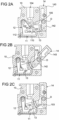
2A-2C Schnittansichten der Anschlussvorrichtung, wobei das Klemmelement, der Schieber und der Hebel in unterschiedlichen Stellungen gezeigt sind; -
3 eine Ansicht des Schiebers; -
4 eine Ansicht des Hebels; -
5 eine Ansicht des Gehäuses; und -
6 eine Ansicht der Anschlussvorrichtung mit eingestecktem elektrischem Leiter.
-
1 a view of a connection device for connecting an electrical conductor with a housing, a current bar, a clamping element, a slide and a lever; -
2A-2C Sectional views of the connecting device, showing the clamping element, the slide and the lever in different positions; -
3 a view of the slider; -
4 a view of the lever; -
5 a view of the housing; and -
6 a view of the connection device with an inserted electrical conductor.
Die Anschlussvorrichtung 1 umfasst ein Gehäuse 10, an dem eine Stecköffnung 104 geformt ist, in die der elektrische Leiter 2 entlang einer Einsteckrichtung E eingesteckt werden kann. Das Gehäuse 10 begrenzt einen Innenraum 100 (in Form einer Kammer), in die der elektrische Leiter 2 mit einem (abisolierten) Leiterende durch Einstecken in die Stecköffnung 104 eingeführt werden kann, um innerhalb des Innenraums 100 mit einem im Gehäuse 10 angeordneten Strombalken 11 elektrisch zu kontaktieren. Optional ist das Gehäuse 10 durch einen in den Figuren nicht gezeigten Deckel verschlossen. Das Gehäuse 10 ist aus einem Isolierstoff gefertigt, z.B. aus einem Kunststoff.The connection device 1 comprises a
Der Strombalken 11 weist einen Balkenabschnitt 110 auf, der sich abschnittsweise entlang einer Wand des Gehäuses 10 erstreckt, und zwar vorliegend im Innenraum 100. Im gezeigten Beispiel umfasst der Strombalken 11 einen aus dem Gehäuse 10 geführten Verbindungsabschnitt, der zum Aufbau einer elektrischen Verbindung mit einer anderen Komponente dient. Über den Strombalken 11 ist der in den Innenraum 100 eingesteckte elektrische Leiter 2 mit der anderen Komponente elektrisch verbindbar. Am Strombalken 11 ist ferner ein Anschlag 111, hier in Form einer vorstehenden Kante, ausgebildet. Der Anschlag 111 ist an einem Teil des Balkenabschnitts 110 ausgebildet, der sich parallel zur Einsteckrichtung E erstreckt. Ferner weist der Strombalken 11 einen Anlageabschnitt 112 auf, der vorliegend vom Balkenabschnitt 110 absteht. Der Anlageabschnitt 112 ist an einer Seite des Innenraums 100 angeordnet, der Anschlag 111 an einer dazu gegenüberliegenden Seite.The
Um den eingesteckten elektrischen Leiter 2 sicher mit dem Strombalken 11 elektrisch zu kontaktieren, umfasst die Anschlussvorrichtung 1 ein Klemmelement 12 mit einem Klemmabschnitt 120, der aus einer Klemmstellung, in welcher der elektrische Leiter 2 mittels des Klemmabschnitts 120 gegen den Strombalken 11 klemmbar ist, in eine Freigabestellung überführbar ist. Die Klemmstellung ist in den
Das Klemmelement 12 ist in Form eines gebogenen Federelements ausgebildet, hier in Form einer Schenkelfeder. Das Klemmelement 12 ist vorliegend einstückig ausgebildet, z.B. durch Stanzen und Biegen eines Stücks Federstahl hergestellt. Der Klemmabschnitt 120 wird durch einen Schenkel der Schenkelfeder ausgebildet. Ein Halteabschnitt 122 des Klemmelements 12 wird durch den anderen Schenkel ausgebildet. Der Halteabschnitt 122 und der Klemmabschnitt 120 sind über eine Biegung 121 miteinander verbunden. Der Haltabschnitt 122 liegt im Gehäuse 10 an einem Anlageabschnitt 112 des Strombalkens 11 an.The clamping
Der Klemmabschnitt 120 kann relativ zum Halteabschnitt 122 verlagert werden, wobei sich insbesondere die Biegung 121 elastisch biegt (ihre Krümmung verändert). Die Biegung 121 erstreckt sich im Gehäuse 10 um eine Halterung 101 des Gehäuses 10 herum. Der Halteabschnitt 122 liegt am Anlageabschnitt 112 des Strombalkens 11 an, vorliegend mit einem freien Ende des Halteabschnitts 122. Hierdurch kann verhindert werden, dass der Halteabschnitt 122 bei einer Verlagerung des Klemmabschnitts 120 relativ zum Gehäuse 10 aus seiner Halteposition heraus bewegt wird.The clamping
Der Klemmabschnitt 120 liegt in der Klemmstellung am Strombalken 11 oder am zwischen dem Strombalken 11 und dem Klemmabschnitt 120 angeordneten elektrischen Leiter 2 an. Konkret weist der Klemmabschnitt 120 eine Klemmkante 123 auf, die in der Klemmstellung am Anschlag 111 anschlägt, wenn der Innenraum 100 frei ist, und die gegen den elektrischen Leiter 2 drückt, wenn der elektrische Leiter 2 im Innenraum 100 angeordnet ist. Der Anschlag 111 begrenzt den Verstellbereich des Klemmabschnitts 120.In the clamping position, the
Wird der elektrische Leiter 2 in die Stecköffnung 104 eingesteckt, wirkt der als Klemmabschnitt 120 dienende Schenkel des Klemmelements 12 derart auf den elektrischen Leiter 2 ein, dass der elektrische Leiter 2 mechanisch arretiert und zudem elektrisch mit dem Strombalken 11 kontaktiert ist.If the
In der Freigabestellung ist der Klemmabschnitt 120 im Vergleich zur Klemmstellung näher am Halteabschnitt 122 angeordnet. In der Freigabestellung ist der im Innenraum 100 angeordnete elektrische Leiter 2 entnehmbar.In the release position, the
Der Klemmabschnitt 120 ist in die Klemmstellung vorgespannt. Um den Klemmabschnitt 120 von der Klemmstellung in die Freigabestellung zu überführen, umfasst die Anschlussvorrichtung 1 einen Schieber 13 und einen Hebel 14.The
Der Schieber 13 ist innerhalb des Gehäuses 10 verschiebbar gelagert. Hierzu umfasst das Gehäuse 10 zumindest eine Kulisse 102, 103, mittels welcher der Schieber 13 verschiebbar gelagert ist. Konkret sind im Gehäuse 10 zwei Kulissen 102, 103 zur Führung des Schiebers 13 ausgebildet, siehe insbesondere
Allgemein kann der Schieber 13 zumindest einen Pin 132, 133 aufweisen, der mit der zumindest einen Kulisse 102, 103 in Eingriff steht.In general, the
Wie insbesondere anhand von
Entlang der Kulissen 102, 103 ist der Schieber 13 zwischen einer Haltestellung, in der der Schieber 13 den Klemmabschnitt 120 in der Freigabestellung hält, und einer Anschlussstellung, in der der elektrische Leiter 2 mittels des Klemmelements 12 an den Strombalken 11 klemmbar ist, verschiebbar.The
Die Kulissen 102, 103 sind, z.B. in Form von Vertiefungen im Gehäuse 10 (und entsprechend im Deckel) ausgebildet oder eingebracht. Eine der Kulissen 102, 103, hier die geradlinige Kulisse 103, weist einen verbreiterten Abschnitt auf. Diese Kulisse 103 ist also an einer Stelle erweitert. Der verbreiterte Abschnitt erlaubt eine Bewegung des in der Kulisse 103 aufgenommenen Pins 132 in einer Richtung, die im Winkel zum Verlauf der Führungsbahn der Kulisse steht.The
Der Schieber 13 umfasst im gezeigten Beispiel zwei voneinander beabstandete Seitenwände 136, an denen jeweils zwei Pins 132, 133 ausgebildet sind. Die Seitenwände 136 mit den Pins 132, 133 sind spiegelbildlich zueinander ausgebildet. Die Seitenwände 136 werden über einen Materialabschnitt miteinander verbunden, der die Auslösefläche 135 bildet. An die Auslösefläche 135 grenzt ein abstehender Fuß 137 an. Ferner sind die Seitenwände 136 durch eine hintere Wand miteinander verbunden, an der eine Rastkante 131 ausgebildet ist. Die Rastkante 131 steht vorliegend gegenüber den Seitenwänden 136 vor.In the example shown, the
Im zusammengebauten Zustand erstreckt sich der Balkenabschnitt 110 des Strombalkens 11 zwischen den Seitenwänden 136 des Schiebers 13 sowie zwischen dem die Auslösefläche 135 bildenden Materialabschnitt und der hinteren Wand hindurch.In the assembled state, the
Ferner bilden die Seitenwände 136 jeweils einen Betätigungsbereich 130 aus, der mit dem Klemmabschnitt 120 des Klemmelements 12 zusammenwirkt. Die Betätigungsbereiche 130 sind jeweils an einer Stirnseite der jeweiligen Seitenwand 136 ausgebildet. Vorliegend umfasst das Klemmelement 12 zwei Betätigungsabschnitte 124, zwischen denen ein die Klemmkante 123 ausbildendes Stück des Klemmabschnitts 120 in einem Winkel zu den Betätigungsabschnitten 124 absteht. Die Betätigungsabschnitte 124 sind im gezeigten Beispiel eben. Die Betätigungsbereiche 130 des Schiebers sind jeweils konvex geformt. Wird der Schieber 13 im Gehäuse 10 verschoben, gleiten die Betätigungsbereiche 130 des Schiebers 13 an den Betätigungsabschnitten 124 des Klemmelements 12, sodass der Klemmabschnitt 120 zwischen der Klemmstellung und der Freigabestellung verstellt wird.Furthermore, the
Das Gehäuse 10 weist eine Kante 105 auf, mit der die Rastkante 131 des Schiebers 13 verrasten kann. Ist der Schieber 13 in der Haltestellung angeordnet, dann steht die Rastkante 131 mit der Kante 105 in Eingriff und fixiert den Schieber 13 so in dieser Stellung am Gehäuse 10.The
Der Fuß 137 des Schiebers 13 dient zum einfacheren Lösen eines gesteckten elektrischen Leiters 2. Durch den Fuß 137 kann der Schieber 13 dabei leichter unter den elektrischen Leiter 2 tauchen. Wird nun der elektrische Leiter 2 in den Innenraum 100 eingeführt, dann schlägt dessen Ende an der Auslösefläche 135 an. Der Schieber 13 ist durch einen durch den elektrischen Leiter 2 ausgeübten Druck auf die Auslösefläche 135 relativ zum Gehäuse 10 verlagerbar, sodass die Rastkante 131 des Schiebers 13 außer Eingriff mit der Kante 105 des Gehäuses 10 gebracht wird. Konkret wird hierbei der Schieber 13 am Gehäuse 10 rotiert. Der Pin 133 gibt dabei einen Drehpunkt vor. Der verbreiterte Abschnitt der Kulisse 103 ermöglicht diese Rotation. Infolge der Rotation des Schiebers 13 gelangt die Rastkante 131 außer Eingriff mit der Kante 105 des Gehäuses 10 und der Schieber 13 wird durch die Federkraft des Klemmelements 12 durch die Kulissen 102, 103 geführt in die Anschlussstellung verlagert, siehe z.B.
Um den Schieber 13 aus der Anschlussstellung in die Haltestellung zu verlagern, kann der Hebel 14 betätigt werden. Der Hebel 14 ist an einer relativ zum Gehäuse 10 fixen Lagerstelle 106 um eine Drehachse D schwenkbar am Gehäuse 10 gelagert. Die Lagerstelle 106 ist im Allgemeinen am Gehäuse 10 ausgebildet oder daran befestigt. Der Hebel 14 ist zwischen einer in
Der in
Einer der Hebelarme 142 weist beiderseits Betätigungsbereiche 144 auf, über die der Hebelarm 142 mit dem Schieber 13 zusammenwirkt. Der andere Hebelarm 143 ist durch einen Benutzer, z.B. manuell oder mit einem Werkzeug, betätigbar. Der Hebelarm 142 mit den Betätigungsbereichen 144 ist kürzer als der andere Hebelarm 143.One of the
Wird der Hebel 14 am betätigbaren Hebelarm 143 betätigt und relativ zum Gehäuse 10 um die Drehachse D von der Ausgangsstellung in die Betätigungsstellung geschwenkt, dann gleiten die Betätigungsbereiche 144 an Flächen 134 des Schiebers 13 entlang. Diese Flächen 134 des Schiebers 13 sind konkav geformt. Da der Hebel 14 um die Drehachse D geschwenkt wird, drücken die Betätigungsbereiche 144 den Schieber 13 entlang der Kulissen 102, 103 und drängen die Rastkante 131 in den Eingriff mit der Kante 105 des Gehäuses 10. Dadurch wird der Klemmabschnitt 120 in der Klemmstellung arretiert. Der Hebel 14 kann sodann in die Ausgangsstellung zurückgestellt werden. Die Anschlussvorrichtung 1 ist geöffnet und gespannt. Das Gehäuse 10 weist jeweils einen Anschlag auf, an den der Hebel 14 in der Ausgangsstellung sowie in der Betätigungsstellung anschlägt.If the
Wird der elektrische Leiter 2 eingeführt, löst die Anschlusseinrichtung 1 automatisch aus und kontaktiert den elektrischen Leiter 2 klemmend mit dem Strombalken 11. Um den elektrischen Leiter 2 wieder zu entsperren, wird der Hebel 14 erneut betätigt, sodass der Schieber 13 das Klemmelement 12 spannt und den als Anschlusskammer dienenden Innenraum 100 öffnet. Starre elektrische Leiter können unabhängig vom Zustand der Anschlussvorrichtung 1 im Push-In-Prinzip (also durch bloßes Einstecken) auch angeschlossen werden, wenn der Klemmabschnitt 120 in der Klemmstellung angeordnet, also nicht in die Freigabestellung gespannt ist.If the
Der Schieber 13 ist zwischen dem Hebel 14 und dem Klemmelement 12 angeordnet. Der Hebel 14 übt bei einer Betätigung eine Kraft in einer Richtung auf den Schieber 13 aus, der dadurch in derselben Richtung eine Kraft auf das Klemmelement 12, genauer: auf den Klemmabschnitt 120, ausübt. Der Klemmabschnitt 120 ist (insbesondere in jeder Stellung des Schiebers 13) zwischen dem Schieber 13 und dem Halteabschnitt 122 angeordnet.The
Mit der Anschlussvorrichtung 1 wird eine besonders intuitive und komfortable Bedienung ermöglicht. Ferner weist die Mechanik eine besonders geringe Neigung zum Verkanten auf und zudem ist die Anschlussvorrichtung 1 mit besonders wenigen Teilen realisierbar. Die Anschlussvorrichtung 1 erlaubt eine automatische Auslösung des Klemmelements 12 und es ist z.B. nicht nötig, zusätzlich zum Einführen des elektrischen Leiters 2 ein Bauteil der Anschlussvorrichtung manuell zu verstellen. Dies wird wie beschrieben dadurch erzielt, dass eine Feder, das Klemmelement 12) durch ein kulissengeführtes Verrastelement (den Schieber 13) und den zweiarmigen Hebel betätigt wird. Die Drehbewegung des Hebels 14 um die Drehachse D versetzt das Verrastelement in Bewegung. Das Verrastelement spannt die Feder und verrastet mit dem Gehäuse 10.With the connection device 1 a particularly intuitive and comfortable operation is made possible. Furthermore, the mechanism has a particularly low tendency to tilt, and the connection device 1 can also be realized with particularly few parts. The connecting device 1 allows the clamping
Es sei darauf hingewiesen, dass der Schieber 13 mit zwei spiegelbildlich ausgebildeten Seitenwänden 136 mit Pins 132, 133 beschrieben wurde. Es ist aber auch denkbar, dass der Schieber mit nur einer Seitenwand 136 und/oder nur mit Pins 132, 133 an einer Seitenwand 136 ausgebildet wird. Entsprechend können Kulissen 102, 103 nur an einer Seite des Schiebers 13 ausgebildet sein und es kann vorgesehen sein, dass der Klemmabschnitt 120 nur einen Betätigungsabschnitt 124 aufweist. Entsprechendes gilt für die Flächen 134 und die Betätigungsbereiche 144. Die Bauteile der Anschlussvorrichtung 1 können sowohl in einem ein- als auch in einem zweischaligen Gehäuse gelagert sein.It should be pointed out that the
BezugszeichenlisteReference List
- 11
- Anschlussvorrichtungconnection device
- 1010
- GehäuseHousing
- 100100
- Innenrauminner space
- 101101
- Halterungbracket
- 102102
- Kulissebackdrop
- 103103
- Kulissebackdrop
- 104104
- Stecköffnungplug opening
- 105105
- Kanteedge
- 106106
- Lagerstellestorage place
- 1111
- Strombalkenpower bar
- 110110
- Balkenabschnittbar section
- 111111
- Anschlagattack
- 112112
- Anlageabschnittinvestment section
- 1212
- Klemmelementclamping element
- 120120
- Klemmabschnittclamping section
- 121121
- Biegungbend
- 122122
- Halteabschnittholding section
- 123123
- Klemmkanteclamping edge
- 124124
- Betätigungsabschnittoperating section
- 1313
- Schieberslider
- 130130
- Betätigungsbereichoperating range
- 131131
- Rastkantelocking edge
- 132132
- PinPin code
- 133133
- PinPin code
- 134134
- FlächeSurface
- 135135
- Auslöseflächerelease surface
- 136136
- SeitenwandSide wall
- 137137
- FußFoot
- 1414
- Hebellever
- 140140
- AufnahmeRecording
- 142142
- Hebelarmlever arm
- 143143
- Hebelarmlever arm
- 144144
- Betätigungsbereichoperating range
- 22
- elektrischer Leiterelectrical conductor
- DD
- Drehachseaxis of rotation
- EE
- Einsteckrichtunginsertion direction
ZITATE ENTHALTEN IN DER BESCHREIBUNGQUOTES INCLUDED IN DESCRIPTION
Diese Liste der vom Anmelder aufgeführten Dokumente wurde automatisiert erzeugt und ist ausschließlich zur besseren Information des Lesers aufgenommen. Die Liste ist nicht Bestandteil der deutschen Patent- bzw. Gebrauchsmusteranmeldung. Das DPMA übernimmt keinerlei Haftung für etwaige Fehler oder Auslassungen.This list of documents cited by the applicant was generated automatically and is included solely for the better information of the reader. The list is not part of the German patent or utility model application. The DPMA assumes no liability for any errors or omissions.
Zitierte PatentliteraturPatent Literature Cited
- DE 102019131141 A1 [0004]DE 102019131141 A1 [0004]
Claims (15)
Priority Applications (2)
| Application Number | Priority Date | Filing Date | Title |
|---|---|---|---|
| DE102021125900.2A DE102021125900A1 (en) | 2021-10-06 | 2021-10-06 | Connection device for connecting an electrical conductor |
| CN202211230602.7A CN115939791A (en) | 2021-10-06 | 2022-10-08 | Connecting device for connecting electrical conductors |
Applications Claiming Priority (1)
| Application Number | Priority Date | Filing Date | Title |
|---|---|---|---|
| DE102021125900.2A DE102021125900A1 (en) | 2021-10-06 | 2021-10-06 | Connection device for connecting an electrical conductor |
Publications (1)
| Publication Number | Publication Date |
|---|---|
| DE102021125900A1 true DE102021125900A1 (en) | 2023-04-06 |
Family
ID=85570979
Family Applications (1)
| Application Number | Title | Priority Date | Filing Date |
|---|---|---|---|
| DE102021125900.2A Pending DE102021125900A1 (en) | 2021-10-06 | 2021-10-06 | Connection device for connecting an electrical conductor |
Country Status (2)
| Country | Link |
|---|---|
| CN (1) | CN115939791A (en) |
| DE (1) | DE102021125900A1 (en) |
Citations (1)
| Publication number | Priority date | Publication date | Assignee | Title |
|---|---|---|---|---|
| DE102019131141A1 (en) | 2019-11-19 | 2021-05-20 | Phoenix Contact Gmbh & Co. Kg | Terminal arrangement, connector terminal and electronic device |
Family Cites Families (3)
| Publication number | Priority date | Publication date | Assignee | Title |
|---|---|---|---|---|
| DE202017107202U1 (en) * | 2017-11-28 | 2019-04-04 | Weidmüller Interface GmbH & Co. KG | Connecting device for connecting a conductor end |
| CN109713463B (en) * | 2018-11-07 | 2020-08-14 | 苏州华旃航天电器有限公司 | Electric connector capable of locking wires quickly |
| CN111786142A (en) * | 2020-07-28 | 2020-10-16 | 天立电机(宁波)有限公司 | A shrapnel type terminal and terminal block |
-
2021
- 2021-10-06 DE DE102021125900.2A patent/DE102021125900A1/en active Pending
-
2022
- 2022-10-08 CN CN202211230602.7A patent/CN115939791A/en active Pending
Patent Citations (1)
| Publication number | Priority date | Publication date | Assignee | Title |
|---|---|---|---|---|
| DE102019131141A1 (en) | 2019-11-19 | 2021-05-20 | Phoenix Contact Gmbh & Co. Kg | Terminal arrangement, connector terminal and electronic device |
Also Published As
| Publication number | Publication date |
|---|---|
| CN115939791A (en) | 2023-04-07 |
Similar Documents
| Publication | Publication Date | Title |
|---|---|---|
| DE102022100132A1 (en) | Electrical connection device | |
| DE10392590B4 (en) | Cable connector latch assembly | |
| DE102021128055A1 (en) | Connection device for connecting an electrical conductor | |
| EP2316150A1 (en) | Electrical terminal | |
| DE202019105075U1 (en) | Terminal for conductors | |
| DE102017106720A1 (en) | Compact conductor connection terminal | |
| DE202019101806U1 (en) | Electrical connector assembly and holding element therefor | |
| EP3813198B1 (en) | Connection device for connecting an electrical line | |
| DE102024134934A1 (en) | conductor connection terminal | |
| EP3685473A1 (en) | Connection device for connecting an electrical cable | |
| DE102019131143A1 (en) | Connection device for connecting an electrical line | |
| DE102017127378A1 (en) | Connecting device for connecting an electrical line | |
| DE102021125900A1 (en) | Connection device for connecting an electrical conductor | |
| DE102022127534A1 (en) | Electrical connection device with pivoting actuating element | |
| DE102020123141A1 (en) | Spring-loaded terminal with actuating element | |
| DE102022100165A1 (en) | Electrical connection device | |
| DE202023107155U1 (en) | Spring clamp connection, conductor connection terminal and guide sleeve | |
| DE102021124872A1 (en) | Electrical connection device with a rotary element | |
| DE102021125901A1 (en) | Connection device for connecting an electrical conductor | |
| DE102021125904A1 (en) | Electrical connection device with a multi-part actuating device | |
| DE102022127531A1 (en) | Electrical connection device with asymmetrical clamping spring | |
| DE102024104287A1 (en) | SNAP-IN CLAMP FOR LADDER | |
| DE102024114956A1 (en) | Terminal block for connecting an electrical line | |
| DE202023105738U1 (en) | Conductor connection terminal for connecting an electrical conductor | |
| DE202024104669U1 (en) | Spring clamp connection and conductor connection terminal |