DE202019105075U1 - Terminal for conductors - Google Patents
Terminal for conductors Download PDFInfo
- Publication number
- DE202019105075U1 DE202019105075U1 DE202019105075.6U DE202019105075U DE202019105075U1 DE 202019105075 U1 DE202019105075 U1 DE 202019105075U1 DE 202019105075 U DE202019105075 U DE 202019105075U DE 202019105075 U1 DE202019105075 U1 DE 202019105075U1
- Authority
- DE
- Germany
- Prior art keywords
- terminal
- conductor
- housing
- clamping
- push
- Prior art date
- Legal status (The legal status is an assumption and is not a legal conclusion. Google has not performed a legal analysis and makes no representation as to the accuracy of the status listed.)
- Active
Links
Images


Classifications
-
- H—ELECTRICITY
- H01—ELECTRIC ELEMENTS
- H01R—ELECTRICALLY-CONDUCTIVE CONNECTIONS; STRUCTURAL ASSOCIATIONS OF A PLURALITY OF MUTUALLY-INSULATED ELECTRICAL CONNECTING ELEMENTS; COUPLING DEVICES; CURRENT COLLECTORS
- H01R13/00—Details of coupling devices of the kinds covered by groups H01R12/70 or H01R24/00 - H01R33/00
- H01R13/02—Contact members
- H01R13/193—Means for increasing contact pressure at the end of engagement of coupling part, e.g. zero insertion force or no friction
-
- H—ELECTRICITY
- H01—ELECTRIC ELEMENTS
- H01R—ELECTRICALLY-CONDUCTIVE CONNECTIONS; STRUCTURAL ASSOCIATIONS OF A PLURALITY OF MUTUALLY-INSULATED ELECTRICAL CONNECTING ELEMENTS; COUPLING DEVICES; CURRENT COLLECTORS
- H01R4/00—Electrically-conductive connections between two or more conductive members in direct contact, i.e. touching one another; Means for effecting or maintaining such contact; Electrically-conductive connections having two or more spaced connecting locations for conductors and using contact members penetrating insulation
- H01R4/28—Clamped connections, spring connections
- H01R4/48—Clamped connections, spring connections utilising a spring, clip, or other resilient member
- H01R4/4809—Clamped connections, spring connections utilising a spring, clip, or other resilient member using a leaf spring to bias the conductor toward the busbar
- H01R4/4828—Spring-activating arrangements mounted on or integrally formed with the spring housing
- H01R4/483—Pivoting arrangements, e.g. lever pushing on the spring
-
- H—ELECTRICITY
- H01—ELECTRIC ELEMENTS
- H01R—ELECTRICALLY-CONDUCTIVE CONNECTIONS; STRUCTURAL ASSOCIATIONS OF A PLURALITY OF MUTUALLY-INSULATED ELECTRICAL CONNECTING ELEMENTS; COUPLING DEVICES; CURRENT COLLECTORS
- H01R4/00—Electrically-conductive connections between two or more conductive members in direct contact, i.e. touching one another; Means for effecting or maintaining such contact; Electrically-conductive connections having two or more spaced connecting locations for conductors and using contact members penetrating insulation
- H01R4/28—Clamped connections, spring connections
- H01R4/48—Clamped connections, spring connections utilising a spring, clip, or other resilient member
- H01R4/4809—Clamped connections, spring connections utilising a spring, clip, or other resilient member using a leaf spring to bias the conductor toward the busbar
- H01R4/48185—Clamped connections, spring connections utilising a spring, clip, or other resilient member using a leaf spring to bias the conductor toward the busbar adapted for axial insertion of a wire end
- H01R4/4819—Clamped connections, spring connections utilising a spring, clip, or other resilient member using a leaf spring to bias the conductor toward the busbar adapted for axial insertion of a wire end the spring shape allowing insertion of the conductor end when the spring is unbiased
- H01R4/4821—Single-blade spring
-
- H—ELECTRICITY
- H01—ELECTRIC ELEMENTS
- H01R—ELECTRICALLY-CONDUCTIVE CONNECTIONS; STRUCTURAL ASSOCIATIONS OF A PLURALITY OF MUTUALLY-INSULATED ELECTRICAL CONNECTING ELEMENTS; COUPLING DEVICES; CURRENT COLLECTORS
- H01R4/00—Electrically-conductive connections between two or more conductive members in direct contact, i.e. touching one another; Means for effecting or maintaining such contact; Electrically-conductive connections having two or more spaced connecting locations for conductors and using contact members penetrating insulation
- H01R4/28—Clamped connections, spring connections
- H01R4/48—Clamped connections, spring connections utilising a spring, clip, or other resilient member
- H01R4/4809—Clamped connections, spring connections utilising a spring, clip, or other resilient member using a leaf spring to bias the conductor toward the busbar
- H01R4/4828—Spring-activating arrangements mounted on or integrally formed with the spring housing
- H01R4/4835—Mechanically bistable arrangements, e.g. locked by the housing when the spring is biased
-
- H—ELECTRICITY
- H01—ELECTRIC ELEMENTS
- H01R—ELECTRICALLY-CONDUCTIVE CONNECTIONS; STRUCTURAL ASSOCIATIONS OF A PLURALITY OF MUTUALLY-INSULATED ELECTRICAL CONNECTING ELEMENTS; COUPLING DEVICES; CURRENT COLLECTORS
- H01R4/00—Electrically-conductive connections between two or more conductive members in direct contact, i.e. touching one another; Means for effecting or maintaining such contact; Electrically-conductive connections having two or more spaced connecting locations for conductors and using contact members penetrating insulation
- H01R4/28—Clamped connections, spring connections
- H01R4/48—Clamped connections, spring connections utilising a spring, clip, or other resilient member
- H01R4/4809—Clamped connections, spring connections utilising a spring, clip, or other resilient member using a leaf spring to bias the conductor toward the busbar
- H01R4/4846—Busbar details
- H01R4/485—Single busbar common to multiple springs
Landscapes
- Connections Arranged To Contact A Plurality Of Conductors (AREA)
- Details Of Connecting Devices For Male And Female Coupling (AREA)
- Coupling Device And Connection With Printed Circuit (AREA)
Abstract
Anschlussklemme (2) zum Anschluss eines Leiters, die als Direktsteckklemme ausgebildet ist, mit einer in einem Gehäuse (1) angeordneten Klemmfeder (4) mit einem in eine Offen- und Raststellung beweglichen federnden Klemmschenkel (7), zu dessen Niederdrücken in die Offen- und Raststellung zum Einführen eines Leiters eine Betätigungseinrichtung (13) vorgesehen ist, wobei das Gehäuse (1) einen Leitereinführkanal (11) zum Einführen des Leiters in eine Klemmstelle zwischen dem freien Ende des Klemmschenkels (7) und einer Stromschiene (5) aufweist, dadurch gekennzeichnet, dass die Betätigungseinrichtung (13) ein Drückelement (14) und ein mit dem Drückelement (14) zumindest bei einem Öffnen der Klemmstelle zusammenwirkendes Schwenkelement (15) aufweist, wobei wenigstens ein Lösemittel zum Lösen des Rastzustandes des Klemmschenkels (7) der Klemmfeder (4) vorgesehen ist, dass derart ausgelegt ist, dass die Verraststellung durch Einwirken des Leiters bei seinem Einführen auf dieses Lösemittel wieder gelöst werden kann.Connection terminal (2) for connecting a conductor, which is designed as a direct plug-in terminal, with a clamping spring (4) arranged in a housing (1) with a resilient clamping leg (7) that can be moved into an open and latching position, for pressing it down into the open and latching position for inserting a conductor, an actuating device (13) is provided, the housing (1) having a conductor insertion channel (11) for inserting the conductor into a clamping point between the free end of the clamping leg (7) and a busbar (5), thereby characterized in that the actuating device (13) has a push element (14) and a swivel element (15) which interacts with the push element (14) at least when the clamping point is opened, at least one release means for releasing the latching state of the clamping leg (7) of the clamping spring ( 4) it is provided that it is designed in such a way that the latching position wi by the action of the conductor when it is inserted into this solvent Either can be solved.
Description
Die Erfindung betrifft eine Anschlussklemme für Leiter nach dem Oberbegriff des Anspruchs 1.The invention relates to a connection terminal for conductors according to the preamble of
Aus der
Zudem ist es aus der
In der
Aus der
Die Erfindung hat die Aufgabe, eine weitere vorteilhafte Lösung zum Wiederherstellen des Rastzustandes einer als Direktsteckklemme ausgestalteten Anschlussklemme mit einer in einem Offen-Zustand verrastbaren Klemmfeder zu schaffen.The invention has the object of creating a further advantageous solution for restoring the latching state of a connection terminal designed as a direct plug-in terminal with a clamping spring that can be latched in an open state.
Die Erfindung löst diese Aufgabe durch den Gegenstand des Anspruchs 1.The invention solves this problem with the subject matter of
Vorteilhafte Ausgestaltungen sind in den Unteransprüchen angegeben.Advantageous refinements are given in the subclaims.
Nach Anspruch 1 wird eine Anschlussklemme zum Anschluss eines Leiters geschaffen, die als Direktsteckklemme ausgebildet ist, mit einer in einem Gehäuse angeordneten Klemmfeder mit einem in eine Offen- und Raststellung beweglichen federnden Klemmschenkel, zu dessen Niederdrücken in die Offen- und vorzugsweise Raststellung zum Einführen eines Leiters eine Betätigungseinrichtung vorgesehen ist, wobei das Gehäuse einen Leitereinführkanal zum Einführen des Leiters in eine Klemmstelle zwischen dem freien Ende des Klemmschenkels der Klemmfeder und eine Stromschiene aufweist, wobei die Betätigungseinrichtung ein Drückelement und ein mit dem Drückelement zumindest beim Öffnen der Klemmstelle zusammenwirkendes Schwenkelement aufweist. Es ist ferner wenigstens ein Lösemittel zum Lösen des Rastzustandes vorgesehen, dass derart ausgelegt ist, dass die Verraststellung durch Einwirken des Leiters bei seinem Einführen auf dieses Lösemittel wieder gelöst werden kann. Da die Betätigungseinrichtung sowohl ein Drückelement als auch ein Schwenkelement aufweist, kann mit Hilfe des Schwenkelementes sowohl die Richtung der Betätigung beim Spannen der Feder als auch die dazu benötigte Kraft auf einfache Weise durch entsprechende Auslegung des Schwenkelementes variiert werden. Eine Verrastung der Klemmfeder im Offenzustand ist dabei eine vorteilhafte Option. Es kann zweckmäßigerweise vorgesehen sein, dass das Schwenkelement zum Einwirken auf das Drückelement und das Drückelement zum Einwirken auf den Klemmschenkel ausgebildet ist. Optional können weitere Lösemittel zum Lösen des Rastzustandes, die anders ausgelegt sind als das erste Lösemittel zum Lösen des Rastzustandes, vorgesehen sein.According to
Nach einer sehr funktionssicheren Variante kann vorgesehen sein, dass das Drückelement in einem Betätigungskanal des Gehäuses linear oder im Wesentlichen linear beweglich ist. Dann ist es zweckmäßig aber nicht zwingend erforderlich, dass der Betätigungskanal parallel zum Leitereinführkanal verläuft.According to a very functionally reliable variant, it can be provided that the pushing element can be moved linearly or essentially linearly in an actuating channel of the housing. Then it is expedient, but not absolutely necessary, for the actuation channel to run parallel to the conductor insertion channel.
Es kann weiter vorteilhaft vorgesehen sein, dass das Drückelement in einer Raststellung verrastbar ist, in welcher es den Klemmschenkel in der Offenstellung zum Einführen des Leiters hält.It can also be advantageously provided that the pushing element can be locked in a latching position in which it holds the clamping leg in the open position for inserting the conductor.
Es kann zudem weiter vorgesehen sein, dass das Schwenkelement in Leitereinführrichtung vor dem Drückelement in dem Betätigungskanal angeordnet ist. Diese Anordnung ist besonders vorteilhaft, aber nicht zwingend. Es kann alternativ aber auch vorgesehen sein, dass das Schwenkelement in Leitereinführrichtung hinter oder neben dem Drückelement in dem Betätigungskanal angeordnet ist.It can also be provided that the swivel element is arranged in the conductor insertion direction in front of the push element in the actuating channel. This arrangement is particularly advantageous, but not mandatory. Alternatively, however, it can also be provided that the swivel element is arranged in the conductor insertion direction behind or next to the pushing element in the actuating channel.
Es ist zur einfachen Betätigung vorteilhaft, wenn das Schwenkelement als Schwenkhebel ausgebildet ist, der schwenkbar in oder am Gehäuse gelagert ist und der einen Drückarm aufweist, mit dem er auf das Drückelement einwirkt und einen Betätigungsarm zum manuellen oder werkzeugbasierten Bewegen des Schwenkhebels.For simple actuation, it is advantageous if the swivel element is designed as a swivel lever which is pivotably mounted in or on the housing and which has a push arm with which it acts on the push element and an actuating arm for manual or tool-based movement of the swivel lever.
Es kann dabei einerseits vorgesehen sein, dass das Schwenkelement mit einem Drehlager mit einer ortsfesten Drehachse an dem Gehäuse schwenkbar gelagert ist. Alternativ kann aber auch vorgesehen sein, dass das Schwenkelement mit einem Drehlager mit einer sich im Raum beim Schwenken des Schwenkelements translatorisch (in einer bis 3 Raumrichtungen nacheinander oder gleichzeitig) bewegenden Drehachse an dem Gehäuse schwenkbar gelagert ist. Derart kann insbesondere der Raumbedarf des Schwenkelementes bei der Drehbewegung entsprechend der jeweiligen Einbauraummaße optimiert werden.On the one hand, it can be provided that the pivot element has a pivot bearing is pivotably mounted with a stationary axis of rotation on the housing. Alternatively, however, it can also be provided that the pivot element is pivotably mounted on the housing with a pivot bearing with a pivot axis that moves translationally in space when the pivot element is pivoted (in one to 3 spatial directions one after the other or simultaneously). In this way, in particular, the space required by the pivoting element during the rotary movement can be optimized in accordance with the respective installation space dimensions.
Nach einer weiteren vorteilhaften Ausgestaltung kann vorgesehen sein, dass das Schwenkelement ganz oder teilweise in dem Betätigungskanal angeordnet ist, insbesondere in dem Betätigungskanal schwenkbar gelagert ist.According to a further advantageous embodiment, it can be provided that the pivot element is arranged wholly or partially in the actuation channel, in particular is pivotably mounted in the actuation channel.
Es kann zudem auch vorgesehen sein, dass das Schwenkelement im Wesentlichen außen auf dem Gehäuse aufliegt und dort außen an dem Gehäuse schwenkbar gelagert ist.It can also be provided that the pivot element rests essentially on the outside of the housing and is mounted there pivotably on the outside of the housing.
Dabei kann nach einer vorteilhaften Variante vorgesehen sein, dass der Drückarm frei ohne Kopplung auf dem Betätigungselement aufliegt, so dass der Schwenkhebel das Drückelement in eine Offen- und Raststellung drücken kann, aber ohne Einfluss auf das Drückelement zurückschwenkbar ist.According to an advantageous variant, it can be provided that the push arm rests freely without coupling on the actuating element, so that the pivot lever can push the push element into an open and latching position, but can be pivoted back without affecting the push element.
Es kann auch vorgesehen sein, dass der Schwenkhebel mit dem Drückelement über eine Koppeleinrichtung gekoppelt ist, sodass der Schwenkhebel das Drückelement in eine Offen- und Raststellung drücken kann und sodass er mit diesem gemeinsam zurückbewegbar ist.It can also be provided that the pivot lever is coupled to the pushing element via a coupling device so that the pivoting lever can push the pushing element into an open and latching position and so that it can be moved back together with it.
Es kann weiter vorgesehen sein, dass das Schwenkelement als optisches Anzeigeelement ausgebildet ist, aus dessen Stellung erkennbar ist, ob sich der Klemmschenkel der Klemmfeder in dem Offen-/ oder in dem Klemmzustand befindet.It can further be provided that the pivot element is designed as an optical display element, from the position of which it can be seen whether the clamping leg of the clamping spring is in the open or in the clamped state.
Es kann zudem vorgesehen sein, dass die Anschlussklemme ein weiteres Löseelement zum Lösen des Rastzustandes des Klemmschenkels der Klemmfeder aufweist.It can also be provided that the connection terminal has a further release element for releasing the latching state of the clamping leg of the clamping spring.
Nach einem nebengeordneten Anspruch wird zudem eine Anschlussklemme zum Anschluss eines Leiters, die als Direktsteckklemme ausgebildet ist, mit einer in einem Gehäuse angeordneten Klemmfeder mit einem in eine Offen- und Raststellung beweglichen federnden Klemmschenkel geschaffen, zu dessen Niederdrücken in die Offen- und Raststellung zum Einführen eines Leiters eine Betätigungseinrichtung vorgesehen ist, wobei das Gehäuse einen Leitereinführkanal zum Einführen des Leiters in eine Klemmstelle zwischen dem freien Ende des Klemmschenkels und einer Stromschiene aufweist, dadurch gekennzeichnet, dass die Betätigungseinrichtung ein Drückelement und ein mit dem Drückelement zumindest bei einem Öffnen der Klemmstelle zusammenwirkendes Schwenkelement aufweist, dadurch gekennzeichnet, dass die Klemmfeder im Gehäuse abgestützt ist und(dies ist eine vorteilhafte aber nicht zwingende Option) nicht mit der Stromschiene verbunden ist und dass die Stromschiene im Bereich der Leitereinführung flächig eben ausgebildet ist und dass der Leiter bei einem Einführen in die Klemmstelle im Übrigen durch das Gehäuse und die Klemmfeder geführt ist. Auch derart wird mit einfachen Mitteln sowie mit besonders wenigen Metallteilen eine weitere vorteilhafte Lösung zum Wiederherstellen des Rastzustandes einer als Direktsteckklemme ausgestalteten Anschlussklemme mit einer in einem Offen-Zustand verrastbaren Klemmfeder geschaffen.According to a subordinate claim, a connection terminal for connecting a conductor, which is designed as a direct plug-in terminal, is provided with a clamping spring arranged in a housing with a resilient clamping leg movable into an open and latching position, for pushing it down into the open and latching position for insertion of a conductor, an actuating device is provided, the housing having a conductor insertion channel for inserting the conductor into a clamping point between the free end of the clamping leg and a busbar, characterized in that the actuating device has a pushing element and one which interacts with the pushing element at least when the clamping point is opened Having swivel element, characterized in that the clamping spring is supported in the housing and (this is an advantageous but not mandatory option) is not connected to the busbar and that the busbar is flat in the area of the conductor entry ben is formed and that the conductor is otherwise guided through the housing and the clamping spring when inserted into the clamping point. In this way, too, a further advantageous solution for restoring the latching state of a connection terminal designed as a direct plug-in terminal with a clamping spring that can be latched in an open state is created with simple means and particularly few metal parts.
Realisierbar sind insbesondere eine Reihenklemme mit einer oder mehreren Anschlussklemmen nach einem der Ansprüche 1 bis 21 sowie ein Steckverbinder oder eine Leiterplattenklemme mit einer Anschlussklemme oder mehreren scheibenartig aufgebauten und aneinander gereihten sowie zu einem Verbund zusammengesetzten Anschlussklemmen nach einem der Ansprüche 1 bis 21.In particular, a series terminal with one or more connection terminals according to one of
Nachfolgend wird die Erfindung unter Bezug auf die Zeichnung beschrieben. Es sei betont, dass lediglich bevorzugte Ausführungsbeispiele beschrieben werden, auf welche der Schutzbereich nicht beschränkt ist. Es sind vielmehr auch Abwandlungen und Äquivalente der dargestellten Ausführungsbeispiele realisierbar. Es zeigen:
-
1 eine perspektivische Ansicht einer Reihenklemme mit zwei als Direktsteckklemmen ausgebildeten Anschlussklemmen; -
2 eine Schnittansicht der Reihenklemme aus1 ; -
3 in a) eine perspektivische Ansicht und in b) eine Seitenansicht eines Teilbereichs einer weiteren Reihenklemme mit einer weiteren Ausgestaltung einer als Direktsteckklemme ausgebildeten Anschlussklemme in einem ersten Betätigungszustand und in c) und d) die Ansichten aus a) bzw. b) in einem zweiten Betätigungszustand; -
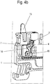
4 in a) eine Seitenansicht und in b) eine perspektivische Ansicht eines Teilbereichs einer dritten Reihenklemme mit einer dritten Variante einer als Direktsteckklemme ausgebildeten Anschlussklemme in einem Klemmzustand und in c) und d) die Reihenklemme aus a) bzw. b) in einem offenen Rastzustand; -
5 in a) eine Schnittansicht und in b) einen vergrößerten Ausschnitt aus a) eines Steckverbinders mit einer vierten Variante einer als Direktsteckklemme ausgebildeten Anschlussklemme in einem offenen Rastzustand sowie in c) eine perspektivische Ansicht des Steckverbinders aus a) in dem Zustand aus a), in d) und e) eine Schnittansicht und eine perspektivische Ansicht des Steckverbinders aus a) mit der Anschlussklemme in einem Klemmzustand und in f) und g) den Steckverbinder aus a) bis e) unmittelbar nach dem Wiederherstellen des offenen Rastzustandes; -
6 in a) bis c) perspektivische Ansicht eines weiteren Steckverbinders in verschiedenen Schalt-Zuständen; -
7 bis9 in a) und b) jeweils Ansichten weiterer Steckverbinder in verschiedenen Schalt-Zuständen; und -
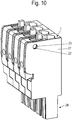
10 ein Steckmodul, das aus einer Reihung von Steckverbindern besteht.
-
1 a perspective view of a terminal block with two connection terminals designed as direct plug-in terminals; -
2 a sectional view of theterminal block 1 ; -
3 in a) a perspective view and in b) a side view of a portion of a further modular terminal with a further embodiment of a connection terminal designed as a direct plug-in terminal in a first actuation state and in c) and d) the views from a) and b) in a second actuation state ; -
4th in a) a side view and in b) a perspective view of a partial area of a third series terminal with a third variant of a connection terminal designed as a direct plug-in terminal in a clamping state and in c) and d) the series terminal from a) and b) in an open latching state; -
5 in a) a sectional view and in b) an enlarged detail from a) of a connector with a fourth variant of a connection terminal designed as a direct plug-in terminal in an open latching state and in c) a perspective view of the connector from a) in the state from a), in d) and e) a sectional view and a perspective view of the connector from a) with the connecting terminal in a clamped state and in f) and g) the connector from a) to e) immediately after restoring the open latching state; -
6 in a) to c) perspective view of another connector in different switching states; -
7th to9 in a) and b) each view of further connectors in different switching states; and -
10 a plug-in module that consists of a series of connectors.
Das Gehäuse
Zudem könnte in dem Gehäuse
Die Anschlussklemme
Nachfolgend wird der Aufbau der beiden Anschlussklemmen
Die Anschlussklemmen
Die jeweilige Klemmfeder
Es sind vorzugsweise jedenfalls abschnittsweise seitlich der Klemmfeder
Der eine der beiden Kanäle
Der andere der beiden Kanäle
Die Betätigungseinrichtung
Das Schwenkelement
Insgesamt wirkt das Schwenkelement
Das Schwenkelement
Das Drückelement
Dabei ist der Schwenkhebel
Vorteilhaft kann durch diese Anordnung ein Verrasten des Klemmschenkels
Nach einer Ausgestaltung kann die Raststellung durch Verrasten des Drückelementes
Wenn das Drückelement
Es könnte auch vorgesehen sein, dass die beiden korrespondierenden Rastkanten nicht im Gehäuse
Es ist also vorgesehen, dass das Drückelement
Sie kann aber nach einer konstruktiv vereinfachten Variante, bei der die Stromschiene dann allerdings keinen Fehlsteckschutz mehr realisiert, flächig eben ausgestaltet sein, so dass kein Klemmkäfig gebildet wird (
Die Klemmfeder kann dabei auch nicht mit der Stromschiene verbunden sein. Sie kann dann im Bereich ihres Bogens und mit ihrem Widerlagerschenkel auch allein im Ggehäuse abgestützt sein und nicht an einem Klemmkäfig oder der Stromschiene oder dgl.The clamping spring can also not be connected to the busbar. It can then be supported solely in the G housing in the area of its arch and with its abutment leg and not on a clamping cage or the busbar or the like.
Nach einer weiteren Option kann diese Verraststellung durch wenigstens ein Lösemittel wieder gelöst werden. Dieses Lösemittel
Die Bedienung der beiden Anschlussklemmen
So kann das Schwenkelement
Zudem kann das Schwenkelement
Die Länge des Betätigungsarmes wirkt sich entscheidend auf die Größe der Kraft aus, die zum Niederdrücken des Drückelementes
Der Betätigungsarm kann insofern kürzer (
Zudem kann mit dem Schwenkelement
Es kann weiter vorgesehen sein, dass der Betätigungshebel im Wesentlichen innerhalb des Betätigungskanals
Das Schwenkelement
Es kann dazu Zapfen aufweisen, die in Ausnehmungen bzw. Augen des Gehäuses
Alternativ kann das Schwenkelement
Es ist aber alternativ auch denkbar, dass das Drehlager keine ortsfeste Drehachse aufweist.Alternatively, however, it is also conceivable that the pivot bearing does not have a fixed axis of rotation.
So kann vorgesehen sein, dass sich der oder die Vorsprünge
Nach
In
Die Drehachse des Vorsprungs
Derart kann insbesondere erreicht werden, dass der Raumbedarf für das Schwenkelement
Auch bei den Ausgestaltungen der
Das Schwenkelement
Es kann weiter vorgesehen sein (
Nach
Die
Nach
Dies ist in
Der Steckverbinder kann einen Steckanschluss
Es ist ferner möglich - siehe
Die Reihenklemmen der
Des Weiteren ist es denkbar eine Abdeckplatte auf die Querseite eines Steckverbinders zu setzen, um die Anschlusseinrichtung im Inneren des Steckverbinders vor äußeren Einflüssen zu schützen und ein Fehlstecken des Leiterendes zu verhindern.Furthermore, it is conceivable to place a cover plate on the transverse side of a connector in order to protect the connection device in the interior of the connector from external influences and to prevent incorrect insertion of the conductor end.
BezugszeichenlisteList of reference symbols
- 11
- Gehäusecasing
- 22
- AnschlussklemmeTerminal
- 33
- StromschienenabschnittBusbar section
- 44th
- KlemmfederClamp spring
- 55
- StromschieneBusbar
- 66th
- StützschenkelSupport leg
- 77th
- KlemmschenkelClamp leg
- 88th
- BiegungBend
- 99
- Stegweb
- 1010
- ZapfenCones
- 1111
- LeitereinführkanalLadder entry channel
- 1212
- BetätigungskanalActuation channel
- 1313
- BetätigungseinrichtungActuator
- 1414th
- DrückelementPush element
- 1515th
- SchwenkelementSwivel element
- 15a, 15b15a, 15b
- HebelarmeLever arms
- 16, 1716, 17
- RastkantenLocking edges
- 1818th
- LösemittelSolvent
- 18a, 18b18a, 18b
- Armepoor
- 2020th
- Fensterwindow
- 2121st
- Stiftepencils
- 2222nd
- AusnehmungenRecesses
- 2323
- VorsprüngeLedges
- 2424
- SteckanschlussPlug connection
- 2525th
- RastfußLocking foot
- 2626th
- RückwandBack wall
- 2727
- Abdeckungcover
- XX
- LeitereinführrichtungConductor entry direction
ZITATE ENTHALTEN IN DER BESCHREIBUNGQUOTES INCLUDED IN THE DESCRIPTION
Diese Liste der vom Anmelder aufgeführten Dokumente wurde automatisiert erzeugt und ist ausschließlich zur besseren Information des Lesers aufgenommen. Die Liste ist nicht Bestandteil der deutschen Patent- bzw. Gebrauchsmusteranmeldung. Das DPMA übernimmt keinerlei Haftung für etwaige Fehler oder Auslassungen.This list of the documents listed by the applicant was generated automatically and is included solely for the better information of the reader. The list is not part of the German patent or utility model application. The DPMA assumes no liability for any errors or omissions.
Zitierte PatentliteraturPatent literature cited
- DE 102004001202 A1 [0002]DE 102004001202 A1 [0002]
- DE 3019149 A1 [0003]DE 3019149 A1 [0003]
- EP 2768079 [0004]EP 2768079 [0004]
- WO 2017/207429 A2 [0005]WO 2017/207429 A2 [0005]
Claims (26)
Priority Applications (5)
| Application Number | Priority Date | Filing Date | Title |
|---|---|---|---|
| DE202019105075.6U DE202019105075U1 (en) | 2019-09-13 | 2019-09-13 | Terminal for conductors |
| PCT/EP2020/074456 WO2021047974A1 (en) | 2019-09-13 | 2020-09-02 | Connection terminal for conductors |
| DE112020004343.6T DE112020004343A5 (en) | 2019-09-13 | 2020-09-02 | Connection terminal for conductor |
| US17/634,737 US11916345B2 (en) | 2019-09-13 | 2020-09-02 | Connection terminal for conductors |
| CN202080064188.XA CN114365355A (en) | 2019-09-13 | 2020-09-02 | Connection terminal for conductors |
Applications Claiming Priority (1)
| Application Number | Priority Date | Filing Date | Title |
|---|---|---|---|
| DE202019105075.6U DE202019105075U1 (en) | 2019-09-13 | 2019-09-13 | Terminal for conductors |
Publications (1)
| Publication Number | Publication Date |
|---|---|
| DE202019105075U1 true DE202019105075U1 (en) | 2020-12-21 |
Family
ID=72355981
Family Applications (2)
| Application Number | Title | Priority Date | Filing Date |
|---|---|---|---|
| DE202019105075.6U Active DE202019105075U1 (en) | 2019-09-13 | 2019-09-13 | Terminal for conductors |
| DE112020004343.6T Pending DE112020004343A5 (en) | 2019-09-13 | 2020-09-02 | Connection terminal for conductor |
Family Applications After (1)
| Application Number | Title | Priority Date | Filing Date |
|---|---|---|---|
| DE112020004343.6T Pending DE112020004343A5 (en) | 2019-09-13 | 2020-09-02 | Connection terminal for conductor |
Country Status (4)
| Country | Link |
|---|---|
| US (1) | US11916345B2 (en) |
| CN (1) | CN114365355A (en) |
| DE (2) | DE202019105075U1 (en) |
| WO (1) | WO2021047974A1 (en) |
Cited By (7)
| Publication number | Priority date | Publication date | Assignee | Title |
|---|---|---|---|---|
| DE102021128055A1 (en) | 2021-10-28 | 2023-05-04 | Phoenix Contact Gmbh & Co. Kg | Connection device for connecting an electrical conductor |
| LU502518B1 (en) * | 2022-07-18 | 2024-01-18 | Phoenix Contact Gmbh & Co | Connection arrangement |
| LU502539B1 (en) | 2022-07-21 | 2024-01-22 | Phoenix Contact Gmbh & Co | Connection arrangement with at least one connection terminal for connecting an electrical line |
| US20240030646A1 (en) * | 2022-07-19 | 2024-01-25 | Weidmüller Interface GmbH & Co. KG | Plug connector |
| DE102022118242A1 (en) | 2022-07-21 | 2024-02-01 | Phoenix Contact Gmbh & Co. Kg | Connection arrangement with at least one connection terminal for connecting an electrical line |
| DE102023133525A1 (en) * | 2023-11-30 | 2025-06-05 | Weidmüller Interface GmbH & Co. KG | Connection terminal for conductors |
| DE202024101057U1 (en) * | 2024-03-05 | 2025-06-12 | WAGO Verwaltungsgesellschaft mit beschränkter Haftung | Spring-cage terminal and conductor connection terminal |
Families Citing this family (9)
| Publication number | Priority date | Publication date | Assignee | Title |
|---|---|---|---|---|
| DE102019131144A1 (en) * | 2019-11-19 | 2021-05-20 | Phoenix Contact Gmbh & Co. Kg | Terminal arrangement, connector terminal and electronic device |
| DE102020123188A1 (en) * | 2020-09-04 | 2022-03-10 | Weidmüller Interface GmbH & Co. KG | Modular connector for contacting a mating connector, in particular a printed circuit board connector |
| DE102021111100B4 (en) * | 2021-04-29 | 2023-10-12 | Weidmüller Interface GmbH & Co. KG | Connection device and method for assembling such a connection device |
| DE102021117396A1 (en) * | 2021-07-06 | 2023-01-12 | Phoenix Contact Gmbh & Co. Kg | Connection arrangement, connection terminal and electronic device |
| LU502919B1 (en) * | 2022-10-19 | 2024-04-19 | Phoenix Contact Gmbh & Co | Connection terminal for connecting an electrical cable |
| LU502926B1 (en) * | 2022-10-19 | 2024-04-19 | Phoenix Contact Gmbh & Co | Connection terminal for connecting an electrical cable |
| US12444883B2 (en) * | 2023-01-26 | 2025-10-14 | Weidmüller Interface GmbH & Co. KG | Snap-in terminal for conductor |
| US20260066555A1 (en) * | 2024-05-03 | 2026-03-05 | Speaker Snap Llc | Detachable terminal block for audio expander control network |
| EP4675857A1 (en) * | 2024-07-03 | 2026-01-07 | TE Connectivity India Private Limited | Wire clamping assembly and connector arrangement |
Citations (9)
| Publication number | Priority date | Publication date | Assignee | Title |
|---|---|---|---|---|
| DE3019149A1 (en) * | 1980-05-20 | 1981-11-26 | Phönix Elektrizitätsgesellschaft H. Knümann GmbH & Co KG, 4933 Blomberg | Screw-less connector for conductor wires - has hairpin spring with one end released to lock bared end against conductive strip |
| DE102004001202A1 (en) * | 2003-01-08 | 2004-07-22 | Bals Elektrotechnik Gmbh & Co. Kg | Electrical cable terminal has spring clip that is released to press contact end securely against the cable wire |
| EP2768079A1 (en) * | 2013-02-19 | 2014-08-20 | Weidmüller Interface GmbH & Co. KG | Spring clamp for conductor |
| DE202015103176U1 (en) * | 2015-06-17 | 2015-06-29 | Dinkle Enterprise Co., Ltd. | Terminal block wiring device |
| EP2947718A1 (en) * | 2014-05-23 | 2015-11-25 | Berker GmbH & Co. KG | Spring loaded clamping connection terminal |
| DE102015118574A1 (en) * | 2015-10-30 | 2017-05-04 | Eaton Electrical Ip Gmbh & Co. Kg | Contacting device for contacting an electrical conductor to an electrical conductor |
| WO2017207429A2 (en) * | 2016-05-30 | 2017-12-07 | Weidmüller Interface GmbH & Co. KG | Spring terminal for a conductor |
| DE102017121543A1 (en) * | 2017-09-18 | 2019-03-21 | Phoenix Contact Gmbh & Co. Kg | Connecting device for connecting an electrical line |
| DE202019101246U1 (en) * | 2018-03-13 | 2019-06-14 | Weidmüller Interface GmbH & Co. KG | Spring terminal for conductor |
Family Cites Families (5)
| Publication number | Priority date | Publication date | Assignee | Title |
|---|---|---|---|---|
| DE1213024B (en) | 1961-09-08 | 1966-03-24 | Siemens Ag | Terminal for screwless conductor connection |
| DE102014119420B3 (en) * | 2014-12-22 | 2016-05-12 | Wago Verwaltungsgesellschaft Mbh | terminal |
| DE102015100823B4 (en) * | 2015-01-21 | 2021-12-09 | Phoenix Contact Gmbh & Co. Kg | Electrical connection terminal |
| US9397444B1 (en) * | 2015-06-01 | 2016-07-19 | Dinkle Enterprise Co., Ltd. | Terminal block wiring device |
| DE102016115601A1 (en) * | 2016-08-23 | 2018-03-01 | Wago Verwaltungsgesellschaft Mbh | Spring terminal connection |
-
2019
- 2019-09-13 DE DE202019105075.6U patent/DE202019105075U1/en active Active
-
2020
- 2020-09-02 CN CN202080064188.XA patent/CN114365355A/en active Pending
- 2020-09-02 US US17/634,737 patent/US11916345B2/en active Active
- 2020-09-02 WO PCT/EP2020/074456 patent/WO2021047974A1/en not_active Ceased
- 2020-09-02 DE DE112020004343.6T patent/DE112020004343A5/en active Pending
Patent Citations (9)
| Publication number | Priority date | Publication date | Assignee | Title |
|---|---|---|---|---|
| DE3019149A1 (en) * | 1980-05-20 | 1981-11-26 | Phönix Elektrizitätsgesellschaft H. Knümann GmbH & Co KG, 4933 Blomberg | Screw-less connector for conductor wires - has hairpin spring with one end released to lock bared end against conductive strip |
| DE102004001202A1 (en) * | 2003-01-08 | 2004-07-22 | Bals Elektrotechnik Gmbh & Co. Kg | Electrical cable terminal has spring clip that is released to press contact end securely against the cable wire |
| EP2768079A1 (en) * | 2013-02-19 | 2014-08-20 | Weidmüller Interface GmbH & Co. KG | Spring clamp for conductor |
| EP2947718A1 (en) * | 2014-05-23 | 2015-11-25 | Berker GmbH & Co. KG | Spring loaded clamping connection terminal |
| DE202015103176U1 (en) * | 2015-06-17 | 2015-06-29 | Dinkle Enterprise Co., Ltd. | Terminal block wiring device |
| DE102015118574A1 (en) * | 2015-10-30 | 2017-05-04 | Eaton Electrical Ip Gmbh & Co. Kg | Contacting device for contacting an electrical conductor to an electrical conductor |
| WO2017207429A2 (en) * | 2016-05-30 | 2017-12-07 | Weidmüller Interface GmbH & Co. KG | Spring terminal for a conductor |
| DE102017121543A1 (en) * | 2017-09-18 | 2019-03-21 | Phoenix Contact Gmbh & Co. Kg | Connecting device for connecting an electrical line |
| DE202019101246U1 (en) * | 2018-03-13 | 2019-06-14 | Weidmüller Interface GmbH & Co. KG | Spring terminal for conductor |
Cited By (9)
| Publication number | Priority date | Publication date | Assignee | Title |
|---|---|---|---|---|
| DE102021128055A1 (en) | 2021-10-28 | 2023-05-04 | Phoenix Contact Gmbh & Co. Kg | Connection device for connecting an electrical conductor |
| LU502518B1 (en) * | 2022-07-18 | 2024-01-18 | Phoenix Contact Gmbh & Co | Connection arrangement |
| WO2024017653A1 (en) * | 2022-07-18 | 2024-01-25 | Phoenix Contact Gmbh & Co. Kg | Connection assembly |
| US20240030646A1 (en) * | 2022-07-19 | 2024-01-25 | Weidmüller Interface GmbH & Co. KG | Plug connector |
| LU502539B1 (en) | 2022-07-21 | 2024-01-22 | Phoenix Contact Gmbh & Co | Connection arrangement with at least one connection terminal for connecting an electrical line |
| WO2024017727A1 (en) | 2022-07-21 | 2024-01-25 | Phoenix Contact Gmbh & Co. Kg | Connection arrangement comprising at least one connection terminal for connecting an electrical line |
| DE102022118242A1 (en) | 2022-07-21 | 2024-02-01 | Phoenix Contact Gmbh & Co. Kg | Connection arrangement with at least one connection terminal for connecting an electrical line |
| DE102023133525A1 (en) * | 2023-11-30 | 2025-06-05 | Weidmüller Interface GmbH & Co. KG | Connection terminal for conductors |
| DE202024101057U1 (en) * | 2024-03-05 | 2025-06-12 | WAGO Verwaltungsgesellschaft mit beschränkter Haftung | Spring-cage terminal and conductor connection terminal |
Also Published As
| Publication number | Publication date |
|---|---|
| DE112020004343A5 (en) | 2022-05-25 |
| US11916345B2 (en) | 2024-02-27 |
| US20220320759A1 (en) | 2022-10-06 |
| CN114365355A (en) | 2022-04-15 |
| WO2021047974A1 (en) | 2021-03-18 |
Similar Documents
| Publication | Publication Date | Title |
|---|---|---|
| DE202019105075U1 (en) | Terminal for conductors | |
| DE102022100132A1 (en) | Electrical connection device | |
| DE202019101246U1 (en) | Spring terminal for conductor | |
| DE102008017738A1 (en) | Installation switching device with a spring-type terminal arrangement | |
| DE202017103185U1 (en) | Spring terminal for conductor | |
| DE4433983A1 (en) | Terminal block for electrical installations | |
| DE102017111733A1 (en) | Spring terminal for conductor | |
| DE102019111453A1 (en) | Spring clamp terminal for conductors | |
| EP3843221B1 (en) | Supporting frame for a connector | |
| DE102022111342A1 (en) | Connection device designed as a spring-loaded terminal for connecting a conductor | |
| EP2625747B1 (en) | Additional attachment plug | |
| EP3493333A1 (en) | Electric plug connection for data transmission | |
| DE19530334B4 (en) | Plug arrangement with an actuating slide | |
| WO2023099476A1 (en) | Plug connector having a locking system | |
| EP3698440B1 (en) | Fastening clamp | |
| DE102019128819A1 (en) | Connection device for connecting an electrical line | |
| DE102023133525A1 (en) | Connection terminal for conductors | |
| DE102020126486A1 (en) | Holding frame for a connector | |
| DE202024104668U1 (en) | conductor connection terminal | |
| DE102025119428A1 (en) | conductor connection terminal | |
| DE102025117908A1 (en) | conductor connection terminal | |
| DE202024102624U1 (en) | conductor connection terminal | |
| DE102025132735A1 (en) | Spring clamp connection and conductor connection terminal | |
| DE102025132734A1 (en) | Spring clamp connection and conductor connection terminal | |
| DE102025132732A1 (en) | Spring clamp connection and conductor connection terminal |
Legal Events
| Date | Code | Title | Description |
|---|---|---|---|
| R163 | Identified publications notified | ||
| R207 | Utility model specification | ||
| R082 | Change of representative | ||
| R150 | Utility model maintained after payment of first maintenance fee after three years | ||
| R151 | Utility model maintained after payment of second maintenance fee after six years |