CN116149496A - Trackpads and Laptops - Google Patents
Trackpads and Laptops Download PDFInfo
- Publication number
- CN116149496A CN116149496A CN202211617870.4A CN202211617870A CN116149496A CN 116149496 A CN116149496 A CN 116149496A CN 202211617870 A CN202211617870 A CN 202211617870A CN 116149496 A CN116149496 A CN 116149496A
- Authority
- CN
- China
- Prior art keywords
- touch panel
- connecting shaft
- state
- limiting
- support plates
- Prior art date
- Legal status (The legal status is an assumption and is not a legal conclusion. Google has not performed a legal analysis and makes no representation as to the accuracy of the status listed.)
- Granted
Links
Images


Classifications
-
- G—PHYSICS
- G06—COMPUTING OR CALCULATING; COUNTING
- G06F—ELECTRIC DIGITAL DATA PROCESSING
- G06F3/00—Input arrangements for transferring data to be processed into a form capable of being handled by the computer; Output arrangements for transferring data from processing unit to output unit, e.g. interface arrangements
- G06F3/01—Input arrangements or combined input and output arrangements for interaction between user and computer
- G06F3/03—Arrangements for converting the position or the displacement of a member into a coded form
- G06F3/033—Pointing devices displaced or positioned by the user, e.g. mice, trackballs, pens or joysticks; Accessories therefor
- G06F3/0354—Pointing devices displaced or positioned by the user, e.g. mice, trackballs, pens or joysticks; Accessories therefor with detection of two-dimensional [2D] relative movements between the device, or an operating part thereof, and a plane or surface, e.g. 2D mice, trackballs, pens or pucks
- G06F3/03547—Touch pads, in which fingers can move on a surface
-
- G—PHYSICS
- G06—COMPUTING OR CALCULATING; COUNTING
- G06F—ELECTRIC DIGITAL DATA PROCESSING
- G06F1/00—Details not covered by groups G06F3/00 - G06F13/00 and G06F21/00
- G06F1/16—Constructional details or arrangements
- G06F1/1613—Constructional details or arrangements for portable computers
-
- Y—GENERAL TAGGING OF NEW TECHNOLOGICAL DEVELOPMENTS; GENERAL TAGGING OF CROSS-SECTIONAL TECHNOLOGIES SPANNING OVER SEVERAL SECTIONS OF THE IPC; TECHNICAL SUBJECTS COVERED BY FORMER USPC CROSS-REFERENCE ART COLLECTIONS [XRACs] AND DIGESTS
- Y02—TECHNOLOGIES OR APPLICATIONS FOR MITIGATION OR ADAPTATION AGAINST CLIMATE CHANGE
- Y02E—REDUCTION OF GREENHOUSE GAS [GHG] EMISSIONS, RELATED TO ENERGY GENERATION, TRANSMISSION OR DISTRIBUTION
- Y02E60/00—Enabling technologies; Technologies with a potential or indirect contribution to GHG emissions mitigation
- Y02E60/10—Energy storage using batteries
Landscapes
- Engineering & Computer Science (AREA)
- Theoretical Computer Science (AREA)
- General Engineering & Computer Science (AREA)
- Human Computer Interaction (AREA)
- Physics & Mathematics (AREA)
- General Physics & Mathematics (AREA)
- Computer Hardware Design (AREA)
- Position Input By Displaying (AREA)
Abstract
本发明公开一种触控板和笔记本电脑,其中,触控板包括:连接轴;两个固定件,两个固定件分别固定连接于连接轴的两端,固定件上设有多个在周向上间隔分布的限位凹槽,两个固定件的限位凹槽相向开口;以及两个支撑板,支撑板设置有套接部,套接部套设于连接轴外,两个支撑板的套接部在连接轴的轴向上分布,并沿轴向相背凸设有限位凸部,支撑板可相对连接轴轴向移动,以具有第一位置和第二位置;于第一位置,限位凸部择一限位凹槽卡入,以限制支撑板相对连接轴周向转动;于第二位置,限位凸部脱离限位凹槽,支撑板可相对连接轴周向转动。本发明技术方案中旨在提供一种能脱离于笔记本电脑的设备主体外独立作为鼠标使用的触控板。

The invention discloses a touch panel and a notebook computer, wherein the touch panel comprises: a connecting shaft; The limit grooves distributed upward at intervals, the limit grooves of the two fixing parts open oppositely; and two support plates, the support plates are provided with socket parts, and the socket parts are sleeved outside the connecting shaft, and the two support plates The sleeve parts are distributed in the axial direction of the connecting shaft, and there are limit protrusions protruding oppositely along the axial direction. The support plate can move axially relative to the connecting shaft to have a first position and a second position; at the first position, The limiting protrusion is selected to fit into a limiting groove to limit the circumferential rotation of the support plate relative to the connecting shaft; at the second position, the limiting protrusion is out of the limiting groove, and the supporting plate can rotate circumferentially relative to the connecting shaft. The technical solution of the present invention aims to provide a touch panel that can be separated from the main body of the notebook computer and used as a mouse independently.
Description
技术领域technical field
本发明涉及笔记本电脑技术领域,特别涉及一种触控板和笔记本电脑。The invention relates to the technical field of notebook computers, in particular to a touch panel and a notebook computer.
背景技术Background technique
笔记本电脑一般配备有触控板,由于触控板操作不便,用户只在触控板上进行一些简单操作,涉及到动作频繁的操作,往往需要用到外接鼠标。然而,在用户外出携带笔记本电脑时,还需要另外携带外接鼠标,非常不便,并且,用户时常会忘记携带外接鼠标,只能通过触控板操作,给用户的操作带来很大不便。Laptops are generally equipped with a touchpad. Due to the inconvenient operation of the touchpad, users only perform some simple operations on the touchpad. Operations involving frequent actions often require an external mouse. However, when the user goes out to carry the notebook computer, he also needs to carry an external mouse, which is very inconvenient. Moreover, the user often forgets to carry the external mouse and can only operate it through the touch panel, which brings great inconvenience to the user's operation.
发明内容Contents of the invention
本发明的主要目的是提供一种触控板,旨在提供一种能脱离于笔记本电脑的设备主体外独立作为鼠标使用的触控板。The main purpose of the present invention is to provide a touch panel, aiming to provide a touch panel that can be used as a mouse independently from the device body of the notebook computer.
为实现上述目的,本发明提出的触控板,包括:To achieve the above object, the touch panel proposed by the present invention includes:
连接轴;connecting shaft;
两个固定件,两个所述固定件分别固定连接于所述连接轴的两端,所述固定件上设有多个在周向上间隔分布的限位凹槽,两个所述固定件的所述限位凹槽相向开口;以及Two fixing parts, the two fixing parts are respectively fixedly connected to the two ends of the connecting shaft, the fixing parts are provided with a plurality of spaced spacing grooves in the circumferential direction, the two fixing parts The limiting grooves are open to each other; and
两个支撑板,所述支撑板设置有套接部,所述套接部套设于所述连接轴外,两个所述支撑板的所述套接部在所述连接轴的轴向上分布,并沿轴向相背凸设有限位凸部,所述支撑板可相对所述连接轴轴向移动,以具有第一位置和第二位置;于所述第一位置,所述限位凸部择一所述限位凹槽卡入,以限制所述支撑板相对所述连接轴周向转动;于所述第二位置,所述限位凸部脱离所述限位凹槽,所述支撑板可相对所述连接轴周向转动。Two support plates, the support plates are provided with socket parts, and the socket parts are sleeved outside the connecting shaft, and the socket parts of the two support plates are in the axial direction of the connecting shaft Distributed, and protrude in the opposite direction along the axial direction with a limiting protrusion, the support plate can move axially relative to the connecting shaft to have a first position and a second position; at the first position, the limiting The convex part selects one of the limiting grooves to be snapped into, so as to limit the circumferential rotation of the support plate relative to the connecting shaft; at the second position, the limiting convex part breaks away from the limiting groove, so The supporting plate can rotate circumferentially relative to the connecting shaft.
可选地,两个所述支撑板的同一侧设置有触摸面板,一所述触摸面板设置有至少一压力传感器,于所述第一状态,所述压力传感器电连接于所述设备主体的主控板,于所述第二状态,所述压力传感器通信连接于所述主控板。Optionally, a touch panel is provided on the same side of the two support plates, and one of the touch panels is provided with at least one pressure sensor. In the first state, the pressure sensor is electrically connected to the main body of the device. The control board, in the second state, the pressure sensor is communicatively connected to the main control board.
可选地,每一所述支撑板内均形成有安装腔,所述安装腔内收容安装有电池,所述压力传感器于对应的所述安装腔内固定连接于所述触摸面板以及电连接于所述电池,于所述第一状态,所述电池电连接于所述主控板。Optionally, an installation cavity is formed in each of the support plates, and a battery is accommodated in the installation cavity, and the pressure sensor is fixedly connected to the touch panel in the corresponding installation cavity and electrically connected to the The battery is electrically connected to the main control board in the first state.
可选地,所述支撑板设置有外露的导电部,用以在所述第一状态接触导通于所述设备主体外显露的导电接口,所述导电接口电连接于所述主控板,所述电池电连接于所述导电部。Optionally, the support plate is provided with an exposed conductive part, which is used to contact and conduct with the conductive interface exposed outside the main body of the device in the first state, and the conductive interface is electrically connected to the main control board, The battery is electrically connected to the conductive part.
可选地,所述触控板还包括显露于所述触摸面板的指示灯,所述指示灯电连接于所述电池,用于指示所述电池的电量。Optionally, the touch panel further includes an indicator light exposed on the touch panel, the indicator light is electrically connected to the battery, and is used to indicate the power of the battery.
可选地,于所述第一状态,两所述支撑板的所述触摸面板的相邻侧相拼接。Optionally, in the first state, adjacent sides of the touch panels of the two support plates are spliced together.
可选地,所述触控板还包括滚轮,于所述第一状态,所述滚轮的感应器电连接于所述设备主体的主控板,于所述第二状态,所述滚轮的感应器通信连接于所述主控板;Optionally, the touch panel further includes a scroll wheel. In the first state, the sensor of the scroll wheel is electrically connected to the main control panel of the device body. In the second state, the sensor of the scroll wheel The device is communicatively connected to the main control board;
所述滚轮位于两所述套接部之间,并可转动地套设于所述连接轴,且在轴向上与所述连接轴相对固定,于所述第二状态,所述滚轮较所述触摸面板外凸设置。The roller is located between the two sleeve parts, and is rotatably sleeved on the connecting shaft, and is fixed relative to the connecting shaft in the axial direction. In the second state, the roller is smaller than the connecting shaft. The convex setting of the touch panel is described above.
可选地,所述连接轴在所述滚轮的轴向两侧各设置有一安装环凸,所述触控板还包括两个复位弹簧,两个所述复位弹簧于两所述安装环凸的相背侧套设于所述连接轴,且每一所述复位弹簧的两端分别连接于对应的所述安装环凸和所述套接部,在所述复位弹簧的作用下,所述支撑板具有维持在所述第一位置的趋势。Optionally, the connecting shaft is provided with a mounting ring protrusion on both axial sides of the roller, and the touch panel further includes two return springs, and the two return springs are located between the two mounting ring protrusions. The opposite side is sleeved on the connecting shaft, and the two ends of each return spring are respectively connected to the corresponding installation ring protrusion and the sleeve part, and under the action of the return spring, the support The plate has a tendency to maintain said first position.
可选地,两所述固定件的相对端开设有导向环槽,所述限位凹槽凹设于所述导向环槽,于所述第二位置,所述限位凸部可滑动地插设于所述导向环槽内。Optionally, guide ring grooves are provided at the opposite ends of the two fixing pieces, and the limiting groove is recessed in the guide ring groove. In the second position, the limiting protrusion is slidably inserted into the Set in the guide ring groove.
本发明还提出一种笔记本电脑,包括:The present invention also proposes a notebook computer, comprising:
设备主体;以及the body of the device; and
触控板,于所述第一状态,所述触控板安装于所述设备主体,于所述第二状态,所述触控板脱离所述设备主体,而能独立作为鼠标使用。The touchpad, in the first state, the touchpad is installed on the device main body, in the second state, the touchpad is detached from the device main body, and can be used independently as a mouse.
本发明技术方案设置的触控板包含连接轴、两个固定件和两个支撑板,其中两个固定件分别固定连接在连接轴的两端,两个支撑板套接在连接轴上,且能够绕连接轴旋转。固定件上设有多个限位凹槽,支撑板上设有限位凸部,支撑板上的限位凸部能够卡合在固定件上的限位凹槽中,通过卡合限制了支撑板限位凸部的位置,从而限制了支撑板在连接轴上的位置,又因为固定件上有多个限位凹槽,所以支撑板可以根据需要卡合在连接轴的不同位置,进而两个支撑板的相对位置关系也变得多样,从而增加了用户的可选择性,使得用户可以根据自身的需要选择合适的触控板结构形状,增加了触控板的使用便利性,提高了用户的使用体验。The touch panel provided by the technical solution of the present invention includes a connecting shaft, two fixing pieces and two supporting plates, wherein the two fixing pieces are fixedly connected to both ends of the connecting shaft respectively, and the two supporting plates are sleeved on the connecting shaft, and Can be rotated about the connecting axis. The fixing part is provided with a plurality of limiting grooves, and the supporting plate is provided with a limiting convex part, and the limiting convex parts on the supporting plate can be engaged in the limiting grooves on the fixing part, and the supporting plate is limited by the engagement. The position of the limiting protrusion limits the position of the supporting plate on the connecting shaft, and because there are multiple limiting grooves on the fixing piece, the supporting plate can be engaged in different positions of the connecting shaft according to needs, and then two The relative positional relationship of the support board also becomes various, thereby increasing the selectivity of the user, so that the user can choose the appropriate structure and shape of the touch pad according to his own needs, which increases the convenience of use of the touch pad and improves the user's convenience. Use experience.
附图说明Description of drawings
为了更清楚地说明本发明实施例或现有技术中的技术方案,下面将对实施例或现有技术描述中所需要使用的附图作简单地介绍,显而易见地,下面描述中的附图仅仅是本发明的一些实施例,对于本领域普通技术人员来讲,在不付出创造性劳动的前提下,还可以根据这些附图示出的结构获得其他的附图。In order to more clearly illustrate the technical solutions in the embodiments of the present invention or the prior art, the following will briefly introduce the drawings that need to be used in the description of the embodiments or the prior art. Obviously, the accompanying drawings in the following description are only These are some embodiments of the present invention. For those skilled in the art, other drawings can also be obtained according to the structures shown in these drawings without creative effort.
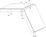
图1为本发明触控板位于第一状态时的结构示意图;1 is a schematic structural view of the touch panel of the present invention when it is in the first state;
图2为本发明触控板位于第二状态时的结构示意图;2 is a schematic structural view of the touch panel of the present invention when it is in the second state;
图3为本发明触控板中部分零件在连接轴上连接的结构示意图;Fig. 3 is a schematic structural view of the connection of some parts on the connecting shaft in the touch panel of the present invention;
图4为本发明触控板中固定件的结构示意图;FIG. 4 is a schematic structural view of a fixing member in a touch panel of the present invention;
图5为本发明笔记本电脑中设备主体的结构示意图。Fig. 5 is a schematic structural diagram of the main body of the device in the notebook computer of the present invention.
附图标号说明:Explanation of reference numbers:
本发明目的的实现、功能特点及优点将结合实施例,参照附图做进一步说明。The realization of the purpose of the present invention, functional characteristics and advantages will be further described in conjunction with the embodiments and with reference to the accompanying drawings.
具体实施方式Detailed ways
下面将结合本发明实施例中的附图,对本发明实施例中的技术方案进行清楚、完整地描述,显然,所描述的实施例仅仅是本发明的一部分实施例,而不是全部的实施例。基于本发明中的实施例,本领域普通技术人员在没有作出创造性劳动前提下所获得的所有其他实施例,都属于本发明保护的范围。The following will clearly and completely describe the technical solutions in the embodiments of the present invention with reference to the accompanying drawings in the embodiments of the present invention. Obviously, the described embodiments are only part of the embodiments of the present invention, not all of them. Based on the embodiments of the present invention, all other embodiments obtained by persons of ordinary skill in the art without creative efforts fall within the protection scope of the present invention.
需要说明,本发明实施例中所有方向性指示(诸如上、下、左、右、前、后……)仅用于解释在某一特定姿态(如附图所示)下各部件之间的相对位置关系、运动情况等,如果该特定姿态发生改变时,则该方向性指示也相应地随之改变。It should be noted that all directional indications (such as up, down, left, right, front, back...) in the embodiments of the present invention are only used to explain the relationship between the components in a certain posture (as shown in the accompanying drawings). Relative positional relationship, movement conditions, etc., if the specific posture changes, the directional indication will also change accordingly.
在本发明中,除非另有明确的规定和限定,术语“连接”、“固定”等应做广义理解,例如,“固定”可以是固定连接,也可以是可拆卸连接,或成一体;可以是机械连接,也可以是电连接;可以是直接相连,也可以通过中间媒介间接相连,可以是两个元件内部的连通或两个元件的相互作用关系,除非另有明确的限定。对于本领域的普通技术人员而言,可以根据具体情况理解上述术语在本发明中的具体含义。In the present invention, unless otherwise specified and limited, the terms "connection" and "fixation" should be understood in a broad sense, for example, "fixation" can be a fixed connection, a detachable connection, or an integral body; It can be a mechanical connection or an electrical connection; it can be a direct connection or an indirect connection through an intermediary, and it can be an internal communication between two elements or an interaction relationship between two elements, unless otherwise clearly defined. Those of ordinary skill in the art can understand the specific meanings of the above terms in the present invention according to specific situations.
另外,若本发明实施例中有涉及“第一”、“第二”等的描述,则该“第一”、“第二”等的描述仅用于描述目的,而不能理解为指示或暗示其相对重要性或者隐含指明所指示的技术特征的数量。由此,限定有“第一”、“第二”的特征可以明示或者隐含地包括至少一个该特征。另外,全文中出现的“和/或”的含义,包括三个并列的方案,以“A和/或B”为例,包括A方案、或B方案、或A和B同时满足的方案。另外,各个实施例之间的技术方案可以相互结合,但是必须是以本领域普通技术人员能够实现为基础,当技术方案的结合出现相互矛盾或无法实现时应当认为这种技术方案的结合不存在,也不在本发明要求的保护范围之内。In addition, if there are descriptions involving "first", "second" and so on in the embodiments of the present invention, the descriptions of "first", "second" and so on are only for descriptive purposes, and should not be interpreted as indicating or implying Its relative importance or implicitly indicates the number of technical features indicated. Thus, the features defined as "first" and "second" may explicitly or implicitly include at least one of these features. In addition, the meaning of "and/or" appearing in the whole text includes three parallel schemes, taking "A and/or B" as an example, including scheme A, scheme B, or schemes that both A and B satisfy. In addition, the technical solutions of the various embodiments can be combined with each other, but it must be based on the realization of those skilled in the art. When the combination of technical solutions is contradictory or cannot be realized, it should be considered that the combination of technical solutions does not exist , nor within the scope of protection required by the present invention.
本发明提出一种触控板。The invention provides a touch panel.
在本发明实施例中,该触控板包括:In an embodiment of the present invention, the touch panel includes:
连接轴500;connecting
两个固定件200,两个所述固定件200分别固定连接于所述连接轴500的两端,所述固定件200上设有多个在周向上间隔分布的限位凹槽220,两个所述固定件200的所述限位凹槽220相向开口;以及Two fixing
两个支撑板300,所述支撑板300设置有套接部310,所述套接部310套设于所述连接轴500外,两个所述支撑板300的所述套接部310在所述连接轴500的轴向上分布,并沿轴向相背凸设有限位凸部320,所述支撑板300可相对所述连接轴500轴向移动,以具有第一位置和第二位置;于所述第一位置,所述限位凸部320择一所述限位凹槽220卡入,以限制所述支撑板300相对所述连接轴500周向转动;于所述第二位置,所述限位凸部320脱离所述限位凹槽220,所述支撑板300可相对所述连接轴500周向转动。Two
如图1、图2、图3和图4所示,连接轴500上连接有两个相对设置的固定件200,连接方式为固定连接,分别位于连接轴500的两端,从而使得连接轴500的轴身上有空间供支撑板300连接,该空间位于两个相对设置的固定件200之间。在该连接轴500供支撑板300安装的空间上一共安装有两个支撑板300,支撑板300与连接轴500的连接方式为活动连接,该活动连接使得支撑板300既能在连接轴500上绕着连接轴500的轴心旋转,又能沿着连接轴500的轴向移动。在本实施例中,通过在所述支撑板300上设置有与连接轴500连接的套接部310实现活动连接,这两个支撑板300的套接部310的分布方向与连接轴500的轴向一致。本发明技术方案中的固定件200上设置有多个限位凹槽220(周向),这些限位凹槽220的槽开口是轴向的,位置方向是位于连接轴500轴向的方向。支撑件上设置有限位凸部320,其中连接轴500上的两个固定件200的限位凹槽220相向设置,连接轴500上的两个支撑板300上的限位凸部320相背设置,并且限位凹槽220能够限制限位凸部320在连接轴500轴向上的位置,因为限位凹槽220是在连接轴500周向上设置的,所以固定件200能够限制支撑板300在连接轴500的周向转动。As shown in Fig. 1, Fig. 2, Fig. 3 and Fig. 4, the connecting
本技术方案中,当支撑板300处于第一位置时,限位凹槽220被限位凸部320卡入,并限制限位凸部320的运动时,当支撑板300处于第二位置时,限位凸部320脱离限位凹槽220的限制时为第二位置。可以理解地,限位凸部320可以通过支撑件在连接轴500轴向上的运动来实现第一位置和第二位置的切换,且当限位凸部320脱离限位凹槽220的限制位于第二位置时,支撑件可以绕连接轴500旋转,从而两个支撑件的相对位置就会随着各自的旋转运动而不断变化,直到支撑件的限位凸部320再次卡入固定件200中的某一个限位凹槽220,实现相对位置的固定。由于固定件200中有多个限位凹槽220,所以两个支撑件在连接轴500上的相对位置也有多个,在触控板作为鼠标使用的第二状态下,可根据用户的手型进行调整两个支撑板300之间的夹角,使得第二状态的触控板能够与用户手部贴合,从而便于用户操作。其中,无论是在触控板的第一状态还是第二状态,支撑板300都能够感应用户的点触操作,以供用户通过触控板对笔记本电脑执行相应的操作。In this technical solution, when the
可以理解地,触控板形状的调整流程为:首先触控板的形状在调整之前,支撑板300都是位于第一位置的,使用者需要先将支撑板300的限位凸部320拔出相对应的限位凹槽220,这一步实现了支撑板300从第一位置到第二位置的转化,也使支撑板300脱离了固定件200的限制,能够绕连接轴500旋转。当支撑板300属于第二位置时,使用者将支撑板300调整到合适的位置之后,再将支撑板300中的限位凸部320插入固定件200的限位凹槽220中,实现了支撑板300从第二位置到第一位置的转换,进而调整了触控板的形状。It can be understood that the adjustment process of the shape of the touchpad is as follows: firstly, before the shape of the touchpad is adjusted, the
由此,在本发明的技术方案中,在触控板的第一状态下,触控板安装于设备主体800,两支撑板300相对展平,也即作为传统触控板使用,以供用户进行简单的点击操作。用户若需要进行更复杂的操作时,可将触控板自设备主体800取下,并调整触控板的形状,以使两支撑板300之间的夹角适配于用户的手部,从而将触控板切换至第二状态,触控板也即能作为鼠标供用户操作。Therefore, in the technical solution of the present invention, in the first state of the touch panel, the touch panel is installed on the device
进一步地,两个所述支撑板300的同一侧设置有触摸面板100,一所述触摸面板100设置有至少一压力传感器,于所述第一状态,所述压力传感器电连接于所述设备主体800的主控板,于所述第二状态,所述压力传感器通信连接于所述主控板。可以理解地,在两个支撑板300的同一侧设置有触摸面板100,即让全部触摸面板100位于触控板的一侧。在本实施例中,是通过在触摸面板100上设置至少一个压力传感器来让触控板的一侧拥有识别外来信息的功能。当然,在其他实施例中可以通过设置电容传感器识别外来信息。即电容传感器电极之间的支架是会随着压力变化而变形的结构,结构的变形进而会导致电容变化,从而可以根据电容的变化来识别信息。Further, a
本技术方案将触控板的状态分成第一状态和第二状态,第一状态即触控板安装于笔记本电脑时的状态,第二状态即触控板与笔记本电脑分离时的状态。当触控板处于第一状态时,压力传感器与设备主体800的主控板电连接,即压力传感器与设备主体800通过导电接通来传送信息,这种连接方式简化了连接步骤和程序,一定程度上提高了组装效率。本技术方案同时规定当触控板处于第二状态时,压力传感器与主控板通信连接,即通过无线连接传送信息,这种连接方式使得设备主体800和触控板在分离状态下,触控板不受设备主体800位置的限制,更好地提高了用户的使用体验。可以理解地,触控板处于第二状态下的操作逻辑与第一状态下的操作逻辑不同,而与鼠标的操作逻辑近似,即触控板内两个触摸面板并不是全部都起操作作用的,其中一个起到支撑的作用,另一个起到操作作用。其中起支撑作用的触摸面板尽管也会识别信息,但是主控板并不会有信息反馈,起操作作用的触摸面板具有在左右方向上分布的两个感应区域,且主控板对左右侧的感应区域的信息处理和信息反馈是不同的,左侧感应区域与鼠标的左键信息处理和信息反馈一致,右侧感应区域与鼠标的右键信息处理和信息反馈一致。进一步地,为便于用户操作,可在起操作作用的触摸面板设置分隔线,以供用户区分左右侧的感应区域。The technical solution divides the state of the touchpad into a first state and a second state. The first state is the state when the touchpad is installed on the notebook computer, and the second state is the state when the touchpad is separated from the notebook computer. When the touch panel is in the first state, the pressure sensor is electrically connected to the main control board of the
进一步地,每一所述支撑板300内均形成有安装腔,所述安装腔内收容安装有电池,所述压力传感器于对应的所述安装腔内固定连接于所述触摸面板100以及电连接于所述电池,于所述第一状态,所述电池电连接于所述主控板。可以理解地,安装腔内电池的设立,可以使得触控板在处于第二状态时有电源来维持通信和接收信息的功能。第一状态下,电池电连接于所述主控板,即可为电池充电,以备第二状态的使用,满足了电池的续航要求,也提高了用户的使用效率。Further, an installation cavity is formed in each of the
进一步地,所述支撑板300设置有外露的导电部,用以在所述第一状态接触导通于所述设备主体800外显露的导电接口,所述导电接口电连接于所述主控板,所述电池电连接于所述导电部。可以理解地,当支撑板300处于第一状态,即支撑板300安装于所述设备主体800时,导电部与导电接口连通。通过外露的导电部与导电接口的连通为电池和主控板提供了一条电路通道,实现了电池的充电需求,不需要过多的充电电子元件,节省了充电成本。当然,在其他实施例中,也可以通过无线充电实现对电池的充电。Further, the
进一步地,所述触控板还包括显露于所述触摸面板100的指示灯,所述指示灯电连接于所述电池,用于指示所述电池的电量。可以理解地,显露于触摸面板100表面的指示灯可以直观的反应触控板内电池的电量,进而用户可以根据电量的多少来决定触控板的使用方式,并在电量较低时及时充电,提高了用户的使用体验和效率。Further, the touch panel further includes an indicator light exposed on the
进一步地,于所述第一状态,两所述支撑板300的所述触摸面板100的相邻侧相拼接。可以理解地,两支撑板300的同一侧设置有触摸面板100,本技术方案规定将触摸面板100的相邻侧拼接,使得触摸面板100成为了一张整体的触摸面板,消除了两个支撑板对应的触摸面板之间的间隙,进而保护了触摸面板内部的传感器等电子元件远离灰尘的损伤,同时也起到了美化外观的作用。Further, in the first state, adjacent sides of the
进一步地,所述触控板还包括滚轮600,于所述第一状态,所述滚轮600的感应器电连接于所述设备主体800的主控板,于所述第二状态,所述滚轮600的感应器通信连接于所述主控板;所述滚轮600位于两所述套接部310之间,并可转动地套设于所述连接轴500,且在轴向上与所述连接轴500相对固定,于所述第二状态,所述滚轮600较所述触摸面板100外凸设置。可以理解地,在连接轴500上,两个支撑板300套接部310之间设置滚轮600,且该滚轮600能够绕着连接轴500旋转,并在触控板内设有与主控板相连的滚轮600感应器,使得滚轮600的旋转运动也能够被主控板识别并进行相应地处理,提高了用户的使用便捷性和操作多样性。本实施例中,通过在滚轮600轴向两侧设置限位结构来限制滚轮600在轴向上的移动,使滚轮600只有旋转运动,避免了滚轮600的感应器对滚轮600误识别的情况。需要注意的是,当触控板位于第一状态时,滚轮600应该收纳在触控板内部;当触控板位于第二状态时,滚轮600应该相较于触摸面板100外凸设置,使得用户能够直接触碰到滚轮600,从而能够通过滚轮600向主控板发送指令。在本实施例中,触摸面板100上设置有避让槽400,当触控板位于第一状态时,滚轮600收纳于避让槽400内,当触控板位于第二状态时,滚轮600从避让槽400中的槽口处外凸于触摸面板100。本实施例中的触控板还包括弹性材质的防尘罩,当触控板在第一状态时防尘罩卡合于避让槽400,由于触控板的避让槽400连通触控板内部与外部,所以触控板内部有外部灰尘进入的可能,防尘罩的设置预防了触控板的内侧进入灰尘的情况。由于防尘罩是弹性材质的,所以当两个支撑板300相对转动时,可以方便的将防尘罩从避让槽400内拉出而不会损伤触控板的结构。Further, the touch panel also includes a
进一步地,所述连接轴500在所述滚轮600的轴向两侧各设置有一安装环凸,所述触控板还包括两个复位弹簧700,两个所述复位弹簧700于两所述安装环凸的相背侧套设于所述连接轴500,且每一所述复位弹簧700的两端分别连接于对应的所述安装环凸和所述套接部310,在所述复位弹簧700的作用下,所述支撑板300具有维持在所述第一位置的趋势。可以理解地,在本实施例中,滚轮600的轴向两侧的限位机构为安装环凸,限制了滚轮600在连接轴500上的轴向运动,使得滚轮600在轴向上的位置固定不变。安装环凸面向支撑板300的一面设置有复位弹簧700,且复位弹簧700的另一端连接与支撑板300的套接部310。可以理解地,无论支撑板300位于第二位置或第一位置,复位弹簧700始终处于被压缩的状态,会一直对支撑板300产生一个向限位凹槽220槽底部的推力,使得支撑板300的限位凸部320更稳定的被按压在限位凹槽220内,从而增加了支撑板300的稳定性,进而使得触控板在被用户使用时不易分解,提高了用户的使用体验。当然,在其他实施例中,也可以通过限位凹槽220与限位凸部320的磁性吸引产生的磁力来达到相同的效果。Further, the connecting
进一步地,两所述固定件200的相对端开设有导向环槽210,所述限位凹槽220凹设于所述导向环槽210,于所述第二位置,所述限位凸部320可滑动地插设于所述导向环槽210内。导向凹槽的设置会给处于第二位置的限位凸部320施加周向限制,使得限位凸部320在连接轴500周向上,要沿导向凹槽的槽壁移动;在连接轴500轴向上,只能进行第一位置和第二位置的切换,减少了限位凸部320在第二位置的其他滑动可能性,从而提高了限位凸部320在第一位置和第二位置之间切换的速度,相应地节省了用户的切换时间,提高了效率,并提高了使用体验。Further, opposite ends of the two fixing
如图5所示,本发明还提出一种笔记本电脑,该笔记本电脑包括设备主体800和触控板,该触控板的具体结构参照上述实施例,由于触控板采用了上述所有实施例的全部技术方案,因此至少具有上述实施例的技术方案所带来的所有有益效果,在此不再一一赘述。其中于所述第一状态,所述触控板安装于所述设备主体800,于所述第二状态,所述触控板脱离所述设备主体800,而能独立于所述设备主体800外,以作为鼠标使用。As shown in FIG. 5 , the present invention also proposes a notebook computer, which includes a device
以上所述仅为本发明的可选实施例,并非因此限制本发明的专利范围,凡是在本发明的发明构思下,利用本发明说明书及附图内容所作的等效结构变换,或直接/间接运用在其他相关的技术领域均包括在本发明的专利保护范围内。The above descriptions are only optional embodiments of the present invention, and do not limit the patent scope of the present invention. Under the inventive concept of the present invention, the equivalent structural transformation made by using the description of the present invention and the contents of the accompanying drawings, or direct/indirect Application in other related technical fields is included in the patent protection scope of the present invention.
Claims (9)
Priority Applications (1)
| Application Number | Priority Date | Filing Date | Title |
|---|---|---|---|
| CN202211617870.4A CN116149496B (en) | 2022-12-15 | 2022-12-15 | Touch pad and notebook computer |
Applications Claiming Priority (1)
| Application Number | Priority Date | Filing Date | Title |
|---|---|---|---|
| CN202211617870.4A CN116149496B (en) | 2022-12-15 | 2022-12-15 | Touch pad and notebook computer |
Publications (2)
| Publication Number | Publication Date |
|---|---|
| CN116149496A true CN116149496A (en) | 2023-05-23 |
| CN116149496B CN116149496B (en) | 2025-12-19 |
Family
ID=86351723
Family Applications (1)
| Application Number | Title | Priority Date | Filing Date |
|---|---|---|---|
| CN202211617870.4A Active CN116149496B (en) | 2022-12-15 | 2022-12-15 | Touch pad and notebook computer |
Country Status (1)
| Country | Link |
|---|---|
| CN (1) | CN116149496B (en) |
Citations (8)
| Publication number | Priority date | Publication date | Assignee | Title |
|---|---|---|---|---|
| JP2004220535A (en) * | 2002-11-21 | 2004-08-05 | Itsuo Kumazawa | Data input device and user interface system |
| CN103049108A (en) * | 2012-12-19 | 2013-04-17 | 苏州贝腾特电子科技有限公司 | Wireless foldable mouse |
| CN103116419A (en) * | 2013-03-13 | 2013-05-22 | 合肥联宝信息技术有限公司 | Method enabling touchpad to achieve functions of handwriting board and mouse simultaneously |
| US20200209983A1 (en) * | 2018-12-28 | 2020-07-02 | Giga-Byte Technology Co.,Ltd. | Pen-shaped folding mouse |
| CN111381692A (en) * | 2018-12-28 | 2020-07-07 | 技嘉科技股份有限公司 | Pen type folding mouse |
| CN213069648U (en) * | 2020-10-22 | 2021-04-27 | 维沃移动通信有限公司 | Electronic equipment |
| CN114237350A (en) * | 2021-12-23 | 2022-03-25 | 上海创功通讯技术有限公司 | laptop |
| CN219066064U (en) * | 2022-12-15 | 2023-05-23 | 深圳市亿道数码技术有限公司 | Notebook computer |
-
2022
- 2022-12-15 CN CN202211617870.4A patent/CN116149496B/en active Active
Patent Citations (8)
| Publication number | Priority date | Publication date | Assignee | Title |
|---|---|---|---|---|
| JP2004220535A (en) * | 2002-11-21 | 2004-08-05 | Itsuo Kumazawa | Data input device and user interface system |
| CN103049108A (en) * | 2012-12-19 | 2013-04-17 | 苏州贝腾特电子科技有限公司 | Wireless foldable mouse |
| CN103116419A (en) * | 2013-03-13 | 2013-05-22 | 合肥联宝信息技术有限公司 | Method enabling touchpad to achieve functions of handwriting board and mouse simultaneously |
| US20200209983A1 (en) * | 2018-12-28 | 2020-07-02 | Giga-Byte Technology Co.,Ltd. | Pen-shaped folding mouse |
| CN111381692A (en) * | 2018-12-28 | 2020-07-07 | 技嘉科技股份有限公司 | Pen type folding mouse |
| CN213069648U (en) * | 2020-10-22 | 2021-04-27 | 维沃移动通信有限公司 | Electronic equipment |
| CN114237350A (en) * | 2021-12-23 | 2022-03-25 | 上海创功通讯技术有限公司 | laptop |
| CN219066064U (en) * | 2022-12-15 | 2023-05-23 | 深圳市亿道数码技术有限公司 | Notebook computer |
Also Published As
| Publication number | Publication date |
|---|---|
| CN116149496B (en) | 2025-12-19 |
Similar Documents
| Publication | Publication Date | Title |
|---|---|---|
| US10656673B1 (en) | Keyboard device | |
| CN107003696B (en) | Electronic device | |
| JP2014509768A (en) | Cursor control and input device that can be worn on the thumb | |
| CN100380297C (en) | Modular components for self-indexing computer pointing devices | |
| US12105896B2 (en) | Computer mouse module | |
| CN102133000A (en) | Lapdesk with Retractable Touchpad | |
| US8089463B2 (en) | Chargeable wireless mouse attachable to a computer host via a wireless signal receiver having a charging plate | |
| CN207354405U (en) | Touch module, housing unit and electronic device | |
| TWI744076B (en) | Mouse device | |
| CN116149496A (en) | Trackpads and Laptops | |
| US20110084906A1 (en) | Multi-mode mouse with changeable size | |
| EP4141624B1 (en) | Input device and electronic device input system | |
| CN219066064U (en) | Notebook computer | |
| US20140210720A1 (en) | Mouse device | |
| CN115904098A (en) | A touch device and electronic equipment | |
| JP6575613B2 (en) | User interface device, operation unit, connection device, command specifying method and program | |
| CN105304380B (en) | Input unit and electronic equipment | |
| EP3674855B1 (en) | Pen-shaped folding mouse | |
| CN111381692B (en) | Pen type folding mouse | |
| US8253687B2 (en) | Slim mouse | |
| CN112698738A (en) | Touch control pen structure | |
| CN112783339B (en) | Touch pen structure | |
| CN201654720U (en) | Cursor control device | |
| CN214413017U (en) | Bluetooth headset with integrally folded elastic sheet structure | |
| CN113687729B (en) | Remote control equipment |
Legal Events
| Date | Code | Title | Description |
|---|---|---|---|
| PB01 | Publication | ||
| PB01 | Publication | ||
| SE01 | Entry into force of request for substantive examination | ||
| SE01 | Entry into force of request for substantive examination | ||
| GR01 | Patent grant | ||
| GR01 | Patent grant |