CN107003696B - Electronic device - Google Patents
Electronic device Download PDFInfo
- Publication number
- CN107003696B CN107003696B CN201580063255.5A CN201580063255A CN107003696B CN 107003696 B CN107003696 B CN 107003696B CN 201580063255 A CN201580063255 A CN 201580063255A CN 107003696 B CN107003696 B CN 107003696B
- Authority
- CN
- China
- Prior art keywords
- assembly
- electronic device
- touchpad assembly
- edge
- touch panel
- Prior art date
- Legal status (The legal status is an assumption and is not a legal conclusion. Google has not performed a legal analysis and makes no representation as to the accuracy of the status listed.)
- Active
Links
Images


Classifications
-
- G—PHYSICS
- G06—COMPUTING OR CALCULATING; COUNTING
- G06F—ELECTRIC DIGITAL DATA PROCESSING
- G06F1/00—Details not covered by groups G06F3/00 - G06F13/00 and G06F21/00
- G06F1/16—Constructional details or arrangements
- G06F1/1613—Constructional details or arrangements for portable computers
- G06F1/1633—Constructional details or arrangements of portable computers not specific to the type of enclosures covered by groups G06F1/1615 - G06F1/1626
- G06F1/1684—Constructional details or arrangements related to integrated I/O peripherals not covered by groups G06F1/1635 - G06F1/1675
- G06F1/169—Constructional details or arrangements related to integrated I/O peripherals not covered by groups G06F1/1635 - G06F1/1675 the I/O peripheral being an integrated pointing device, e.g. trackball in the palm rest area, mini-joystick integrated between keyboard keys, touch pads or touch stripes
-
- G—PHYSICS
- G06—COMPUTING OR CALCULATING; COUNTING
- G06F—ELECTRIC DIGITAL DATA PROCESSING
- G06F1/00—Details not covered by groups G06F3/00 - G06F13/00 and G06F21/00
- G06F1/16—Constructional details or arrangements
-
- G—PHYSICS
- G06—COMPUTING OR CALCULATING; COUNTING
- G06F—ELECTRIC DIGITAL DATA PROCESSING
- G06F1/00—Details not covered by groups G06F3/00 - G06F13/00 and G06F21/00
- G06F1/16—Constructional details or arrangements
- G06F1/1613—Constructional details or arrangements for portable computers
- G06F1/1615—Constructional details or arrangements for portable computers with several enclosures having relative motions, each enclosure supporting at least one I/O or computing function
- G06F1/1616—Constructional details or arrangements for portable computers with several enclosures having relative motions, each enclosure supporting at least one I/O or computing function with folding flat displays, e.g. laptop computers or notebooks having a clamshell configuration, with body parts pivoting to an open position around an axis parallel to the plane they define in closed position
-
- G—PHYSICS
- G06—COMPUTING OR CALCULATING; COUNTING
- G06F—ELECTRIC DIGITAL DATA PROCESSING
- G06F1/00—Details not covered by groups G06F3/00 - G06F13/00 and G06F21/00
- G06F1/16—Constructional details or arrangements
- G06F1/1613—Constructional details or arrangements for portable computers
- G06F1/1633—Constructional details or arrangements of portable computers not specific to the type of enclosures covered by groups G06F1/1615 - G06F1/1626
- G06F1/1675—Miscellaneous details related to the relative movement between the different enclosures or enclosure parts
- G06F1/1681—Details related solely to hinges
-
- G—PHYSICS
- G06—COMPUTING OR CALCULATING; COUNTING
- G06F—ELECTRIC DIGITAL DATA PROCESSING
- G06F3/00—Input arrangements for transferring data to be processed into a form capable of being handled by the computer; Output arrangements for transferring data from processing unit to output unit, e.g. interface arrangements
- G06F3/01—Input arrangements or combined input and output arrangements for interaction between user and computer
- G06F3/03—Arrangements for converting the position or the displacement of a member into a coded form
- G06F3/033—Pointing devices displaced or positioned by the user, e.g. mice, trackballs, pens or joysticks; Accessories therefor
- G06F3/0354—Pointing devices displaced or positioned by the user, e.g. mice, trackballs, pens or joysticks; Accessories therefor with detection of two-dimensional [2D] relative movements between the device, or an operating part thereof, and a plane or surface, e.g. 2D mice, trackballs, pens or pucks
- G06F3/03547—Touch pads, in which fingers can move on a surface
-
- G—PHYSICS
- G06—COMPUTING OR CALCULATING; COUNTING
- G06F—ELECTRIC DIGITAL DATA PROCESSING
- G06F2203/00—Indexing scheme relating to G06F3/00 - G06F3/048
- G06F2203/041—Indexing scheme relating to G06F3/041 - G06F3/045
- G06F2203/04105—Pressure sensors for measuring the pressure or force exerted on the touch surface without providing the touch position
Landscapes
- Engineering & Computer Science (AREA)
- Theoretical Computer Science (AREA)
- Computer Hardware Design (AREA)
- General Engineering & Computer Science (AREA)
- Physics & Mathematics (AREA)
- Human Computer Interaction (AREA)
- General Physics & Mathematics (AREA)
- Mathematical Physics (AREA)
- Position Input By Displaying (AREA)
Abstract
Description
技术领域technical field
本发明涉及一种能够以有效方式支撑触摸板组件的电子设备。The present invention relates to an electronic device capable of supporting a touch panel assembly in an efficient manner.
背景技术Background technique
诸如TV、个人计算机、膝上型计算机、移动电话以及点书(tap books)的电子设备正在演进成提供包括图像或者视频捕获、音乐或者视频文件的回放、游戏、以及广播节目的接收的各种功能的多媒体播放器。Electronic devices such as TVs, personal computers, laptops, mobile phones, and tap books are evolving to provide a variety of devices including image or video capture, playback of music or video files, gaming, and reception of broadcast programs. Functional multimedia player.
因为它们在依旧保持便携式的同时提供比预先确定的水平更高的性能,所以膝上型计算机的形式的电子设备在各种应用中被使用。此外,鼠标功能被嵌入到电子设备本身以增强便携性;例如,鼠标功能可以以触摸板的形式被嵌入到电子设备。Electronic devices in the form of laptop computers are used in a variety of applications because they provide higher performance than a predetermined level while still remaining portable. Furthermore, mouse functionality is embedded into the electronic device itself to enhance portability; for example, the mouse functionality can be embedded in the electronic device in the form of a touchpad.
当触摸板替换鼠标功能时,重要的是,当操作鼠标以及将鼠标整合到电子设备中时允许用户以相同的方式感知。When the touchpad replaces the mouse function, it is important to allow the user to perceive in the same way when operating the mouse and when integrating the mouse into an electronic device.
发明内容SUMMARY OF THE INVENTION
技术问题technical problem
本发明的目的是为了解决在上面描述的问题和其他有关问题。并且本发明的另一目的是为了提供一种能够以有效的方式支撑触摸板组件的电子设备。It is an object of the present invention to solve the problems described above and other related problems. And another object of the present invention is to provide an electronic device capable of supporting the touch panel assembly in an efficient manner.
技术方案Technical solutions
根据实现在上面描述的目的和其他目的的本发明的一个方面,一种电子设备,包括:第一主体,该第一主体被装备有显示器;第二主体,该第二主体通过铰链被连接到第一主体;通孔,该通孔被形成在第二主体的至少一个区域中;触摸板组件,该触摸板组件被耦接到通孔,该触摸板组件根据用户的压力相对于第二主体可移动;以及支撑条,该支撑条支撑触摸板组件,其中支撑条的一侧被耦接到第二主体,并且支撑条的另一侧接触触摸板组件。According to one aspect of the present invention to achieve the above-described objects and other objects, an electronic device includes: a first body equipped with a display; and a second body connected to a hinge through a hinge a first body; a through hole formed in at least one area of the second body; a touch panel assembly coupled to the through hole, the touch panel assembly being relative to the second body according to a user's pressure movable; and a support bar supporting the touch panel assembly, wherein one side of the support bar is coupled to the second body and the other side of the support bar contacts the touch panel assembly.
触摸板组件可以包括:保护片,通过用户的手指接触保护片的表面;触摸传感器片,该触摸传感器片的表面被耦接到保护片的另一表面;以及加固片,该加固片被耦接到触摸传感器的另一表面,其中支撑条接触加固片以朝向保护片提供弹力。The touch panel assembly may include: a protective sheet, the surface of which is contacted by the user's finger; a touch sensor sheet, the surface of which is coupled to the other surface of the protective sheet; and a reinforcing sheet to which the reinforcing sheet is coupled to the other surface of the touch sensor, where the support bar contacts the reinforcing sheet to provide elasticity towards the protective sheet.
加固片可以包括耦接部分,该耦接部分从加固片的边缘延伸并且被耦接到第二主体,其中当用户将压力施加到触摸板组件时触摸板组件绕着耦接部分相对于第二主体旋转。The reinforcement sheet may include a coupling portion extending from an edge of the reinforcement sheet and coupled to the second body, wherein the touchpad assembly is relative to the second body around the coupling portion when a user applies pressure to the touchpad assembly The body rotates.
加固片的中心区域可以被去除。The central area of the reinforcing sheet can be removed.
耦接部分可以包括多个耦接部分,其中触摸板组件进一步包括多个弹性板,所述多个弹性板被耦接到加固片和第二主体,以及其中多个弹性板给加固片提供恢复力。The coupling portion may include a plurality of coupling portions, wherein the touchpad assembly further includes a plurality of elastic plates coupled to the reinforcing sheet and the second body, and wherein the plurality of elastic plates provide recovery to the reinforcing sheet force.
弹性板可以包括穿透孔和弹性板的两个边缘处形成的多个槽,以及其中穿透孔在多个槽之间。The elastic plate may include penetration holes and a plurality of grooves formed at both edges of the elastic plate, and wherein the penetration holes are between the plurality of grooves.
弹性板可以通过多个槽被分隔成第一区域和第二区域,以及第一区域和第二区域不在相同的平面上。The elastic plate may be divided into a first area and a second area by a plurality of grooves, and the first area and the second area are not on the same plane.
支撑条可以在触摸板组件上保持接触。The support bar can maintain contact on the touchpad assembly.
当在触摸板组件上施加压力时触摸板组件可以绕着触摸板组件的边缘旋转,以及其中支撑条被定位成相邻于与边缘相对的另一边缘。The touchpad assembly can rotate about an edge of the touchpad assembly when pressure is applied on the touchpad assembly, and wherein the support bar is positioned adjacent another edge opposite the edge.
电子设备可以进一步包括:肋,该肋从加固片延伸;突出部分,该突出部分从肋朝向加固片的外部延伸;以及弹性构件,该弹性构件被耦接到第二主体,弹性构件被定位成与突出部分相对应。The electronic device may further include: a rib extending from the reinforcing sheet; a protruding portion extending from the rib toward the outside of the reinforcing sheet; and an elastic member coupled to the second body, the elastic member being positioned to Corresponds to the protruding part.
当触摸板组件上的压力被去除时,突出部分比触摸板组件的其他区域先接触弹性构件。When the pressure on the touchpad assembly is removed, the protruding portion contacts the elastic member before other areas of the touchpad assembly.
有益效果beneficial effect
本发明的有益效果可以被如下地描述。The advantageous effects of the present invention can be described as follows.
根据本发明的实施例中的至少一个,触摸板组件可以以有效的方式被支撑。According to at least one of the embodiments of the present invention, the touchpad assembly can be supported in an efficient manner.
从下面给出的详细描述中可以清楚地理解本发明的附加的范围。然而,因为在本发明的技术原理和范围内本领域的技术人员可以清楚地理解本发明的各种修改和变化,所以应理解的是,为了图示的目的已经简单地提供了诸如本发明的优选实施例的具体实施例和详细描述。Additional scope of the present invention will become apparent from the detailed description given below. However, since various modifications and variations of the present invention can be clearly understood by those skilled in the art within the technical principles and scope of the present invention, it should be understood that such Specific Examples and Detailed Description of Preferred Embodiments.
附图说明Description of drawings
图1图示根据本发明的一个实施例的电子设备。Figure 1 illustrates an electronic device according to one embodiment of the present invention.
图2图示图1的电子设备的触摸板组件。FIG. 2 illustrates a touchpad assembly of the electronic device of FIG. 1 .
图3图示图2的触摸板组件的操作。FIG. 3 illustrates the operation of the touchpad assembly of FIG. 2 .
图4是图2的触摸板组件的分解透视图。FIG. 4 is an exploded perspective view of the touchpad assembly of FIG. 2 .
图5图示图2的触摸板组件的后表面。FIG. 5 illustrates the rear surface of the touchpad assembly of FIG. 2 .
图6图示图5的支撑条。FIG. 6 illustrates the support bar of FIG. 5 .
图7图示图5的支撑条的操作。FIG. 7 illustrates the operation of the support bar of FIG. 5 .
图8图示图5的突出部分和弹性构件。FIG. 8 illustrates the protruding portion and elastic member of FIG. 5 .
图9图示图5的突出部分和弹性构件的操作。FIG. 9 illustrates the operation of the protruding portion and elastic member of FIG. 5 .
图10图示图5的耦接部分的操作。FIG. 10 illustrates the operation of the coupling portion of FIG. 5 .
图11图示图5的弹性板。FIG. 11 illustrates the elastic plate of FIG. 5 .
图12图示图5的弹性板的操作。FIG. 12 illustrates the operation of the resilient plate of FIG. 5 .
具体实施方式Detailed ways
在下文中,将会参考附图详细地描述本发明的优选实施例。应注意的是,相同的附图标记被指配给相互相同或者相似的组成元件,不论它们的附图符号如何,并且将会省略其重复的描述。为了撰写本文档的方便,用于组成在下面的描述中出现的组成元件的后缀“模块”和“部分”被简单互换地指配或者使用,并且不具有被相互区分的特定意义或者作用。此外,在确定用于对于公众已知的有关技术或者方法的具体描述模糊了在本文档中公开的实施例的技术原理的情况下,将会省略其详细描述。此外,应该理解,附图仅旨在帮助理解在本文档中公开的实施例,并且因此不限制在本文档中公开的技术原理而是包括属于本发明的技术原理和范围的所有的修改、等效实现、或者替代。Hereinafter, preferred embodiments of the present invention will be described in detail with reference to the accompanying drawings. It should be noted that the same reference numerals are assigned to mutually identical or similar constituent elements regardless of their reference numerals, and repeated descriptions thereof will be omitted. For the convenience of writing this document, the suffixes 'module' and 'section' used to compose constituent elements appearing in the following description are simply assigned or used interchangeably, and do not have specific meanings or roles distinguished from each other. Also, in the case where it is determined that the specific description for a related technology or method known to the public obscure the technical principles of the embodiments disclosed in this document, the detailed description thereof will be omitted. Further, it should be understood that the accompanying drawings are only intended to aid in understanding the embodiments disclosed in this document, and thus do not limit the technical principles disclosed in this document but include all modifications, etc., which belong to the technical principles and scope of the present invention effective implementation or replacement.
包括诸如第一和第二的序数的术语可以被用于描述各种组成元件,但是通过包括序数的这些术语不限制元件。这些术语仅被用于区分一个组成元件和其他元件的目的。Terms including ordinal numbers such as first and second may be used to describe various constituent elements, but the elements are not limited by these terms including the ordinal numbers. These terms are only used for the purpose of distinguishing one constituent element from other elements.
当组成元件被称为“被连接”到不同的组成元件时,应理解的是,组成元件可以被直接地连接到不同的组成元件,但是第三组成元件可以存在于两个元件之间。另一方面,当组成元件被称为“被直接地连接”到另一元件时,应理解在两个元件之间不存在其他元件。When a constituent element is referred to as being "connected" to a different constituent element, it should be understood that the constituent element may be directly connected to the different constituent element, but a third constituent element may exist between the two elements. On the other hand, when a constituent element is referred to as being "directly connected" to another element, it will be understood that no other element is present between the two elements.
单数表达包括复数表达,除非上下文另有明确其他指示。Singular expressions include plural expressions unless the context clearly dictates otherwise.
应该理解的是,在本文档中使用的术语“包括”或“具有”被引入仅为了指示在本文档中指定的特征、数目、步骤、操作、组成元件、部件或其组合,但不排除一个或多个其他特征、数目、步骤、操作、组成元件、组件或其组合的存在或者添加一个或多个其他特征、数目、步骤、操作、组成元件、组件或其组合的可能性。It should be understood that the terms "comprising" or "having" used in this document are introduced only to indicate the features, numbers, steps, operations, constituent elements, components or combinations thereof specified in this document, but do not exclude a The presence or possibility of adding one or more other features, numbers, steps, operations, constituent elements, components, or combinations thereof, or the possibility of adding one or more other features, numbers, steps, operations, constituent elements, components, or combinations thereof.
在本文档中描述的电子设备可以包括膝上型计算机、数字广播终端、PDA(个人数字助理)、PMP(便携式多媒体播放器)、导航终端、板式PC、平板PC以及超级本。Electronic devices described in this document may include laptop computers, digital broadcast terminals, PDAs (Personal Digital Assistants), PMPs (Portable Multimedia Players), navigation terminals, tablet PCs, tablet PCs, and ultrabooks.
然而,本领域的技术人员应容易理解,除了仅适用于移动终端的情况之外,根据本发明的实施例的结构也可以被应用于诸如数字TV、桌面计算机以及数字标牌的固定终端。However, it should be easily understood by those skilled in the art that the structures according to the embodiments of the present invention can also be applied to stationary terminals such as digital TVs, desktop computers, and digital signage, in addition to the case where only mobile terminals are applied.
图1图示根据本发明的一个实施例的电子设备。Figure 1 illustrates an electronic device according to one embodiment of the present invention.
如在图中所示,根据本发明的一个实施例的电子设备100可以属于其中第一主体110和第二主体210被打开的第一状态或者其中第一主体110和第二主体210被关闭的第二状态。As shown in the drawings, the
如在图1(a)中所示,电子设备100可以处于第一状态中。第一主体110可以通过铰链170被连接到第二主体210。第一主体110可以通过铰链170相对于第二主体210旋转。例如,当第二主体210被固定到底表面时,第一主体110可以旋转以便处于其中第一主体110的前表面的显示器130被暴露于外部的第一状态中。As shown in Figure 1(a), the
第一主体110可以被装备有前述的显示器130和相机150。The
第二主体210可以被装备有获得来自于用户的键输入的键盘230。第二主体210的侧表面可以被装备有至少一个接口250。外部设备可以通过接口250被连接到电子设备100。The
第二主体210可以被装备有能够从用户获得触摸输入的触摸板组件10。该触摸板组件可以位于第二主体210的上壳体215上。因此,当电子设备100处于第一状态时,触摸板组件10可以被暴露于外部。The
如在图1(b)中所示,电子设备100可以处于第二状态中。第二状态可以是其中第一主体110紧密接触第二主体210的状态。在第一状态中,第一主体110的显示器130、第二主体210的键盘230以及触摸板组件10可以不被暴露于外部。As shown in Figure 1(b), the
标识区域70可以被制备在第一主体110的外表面上。The
电子设备100的制造商的标识和/或用于识别电子设备100的用户的图标可以被显示在标识区域70上。当电子设备100在使用时标识区域70可以明亮地发光。例如,当电子设备100是处于第一状态中时标识区域70的发光可以被激活,并且当处于第二状态中时标识区域70的发光可以被停用。An identification of the manufacturer of the
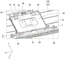
图2图示图1的电子设备的触摸板组件。FIG. 2 illustrates a touchpad assembly of the electronic device of FIG. 1 .
如上所述,根据本发明的实施例的电子设备100可以包括触摸板组件10,该触摸板组件10被耦接到第二主体210的通孔30a。As described above, the
当上壳体215被耦接到下壳体214时第二主体210可以被形成。换言之,各种组件可以被安装在由上壳体215和下壳体214的耦接形成的空间中。The
通孔可以被形成在上壳体215上。上壳体215可以被用于形成第二主体210的外观。上壳体215可以被装备有如上所述的键盘230。Through holes may be formed on the
通孔30a可以被形成在上壳体215的下中心区域中。通孔30a可以被形成以对应于触摸板组件10的形状。通孔30a可以具有矩形。The through
触摸板组件10可以是用于从用户获得触摸输入的模块。通过使用触摸板组件10,用户可以在没有将诸如鼠标的单独的设备连接到电子设备100的情况下操作电子设备100。例如,当在触摸板组件10上的来自于用户的触摸输入被感测时,由用户施加的压力和/或用户的体温被检测,并且鼠标指针可以被移动到触摸位置并且/或者沿着触摸轨迹被移动。The
图3图示图2的触摸板组件的操作。FIG. 3 illustrates the operation of the touchpad assembly of FIG. 2 .
如上所述,根据本发明的一个实施例的触摸板组件10可以根据用户的触摸压力移动预先确定的距离。如果触摸板组件10根据当用户触摸该触摸板组件10时产生的触摸压力移动,则用户可以感觉更加精确的触摸感。As described above, the
如在图3(a)中所示,触摸板组件10的上表面实际可以被布置在与上壳体215相同的平面上。换言之,当用户不触摸该触摸板组件10时,触摸板组件10可以被布置成与上壳体125无缝地集成。As shown in FIG. 3( a ), the upper surface of the
如在图3(b)中所示,用户可以通过使用他的或者她的手指F触摸该触摸板组件10。如果用户触摸该触摸板组件10,则触摸板组件10的至少一部分可以向后移动移动距离MC。换言之,如果手指F在触摸板组件10上产生触摸输入,则触摸板组件10可以与触摸压力的强度成比例地移动。如果触摸板组件10向后移动,则用户可以感觉到与当他或者她按压按钮时感测到的触摸感相似的触摸感。因此,用户可以更加直观地察觉到他或者她已经触摸了触摸板组件10。As shown in FIG. 3(b), the user can touch the
当触摸板组件10被组装时移动距离(MC)可以被适当地调节以对应于用户的触摸操作。例如,用户的触摸操作可以包括至少两种类型。换言之,当手指正在触摸该触摸板组件10时拖动手指(F)的悬停操作和更加强烈地按压触摸板组件10的特定点的点击操作。在悬停操作期间施加的压力可以小于施加用于点击操作的压力。因此,通过调节触摸板组件10的排斥力或者弹力,可以使触摸板组件10在悬停操作时不移动而在点击操作时向后移动。尽管在本文档的相应部分中稍后将会详细地描述,但是根据本发明的一个实施例的触摸板组件10可以确定是否根据由用户施加的压力移动和/或优化移动距离。The moving distance (MC) may be appropriately adjusted to correspond to the user's touch operation when the
图4是图2的触摸板组件的分解透视图,并且图5图示图2的触摸板组件的后表面。FIG. 4 is an exploded perspective view of the touchpad assembly of FIG. 2 , and FIG. 5 illustrates a rear surface of the touchpad assembly of FIG. 2 .
如在附图中示出,根据本发明的一个实施例的电子设备100的触摸板组件10可以包括保护片20、触摸传感器片30、加固片40、弹性板50以及支撑条60。As shown in the drawings, the
保护片20可以被布置在触摸板组件10的顶层处。因此,用户的手指可以直接地接触保护片20。保护片20可以由弹性材料制成。由弹性材料制成的保护片20不同于由玻璃材料制成的传统的材料。因此,能够实现比由玻璃材料制成的保护片更轻的保护片20。The
触摸传感器片30可以被耦接到保护片20的后表面。被耦接到保护片20的后表面的触摸传感器片30可以是能够检测来自于用户的触摸输入的实际设备。触摸传感器片30可以检测触摸位置和/或触摸轨迹。从触摸传感器片30检测到的值可以经由触摸传感器电缆32被递送给电子设备100的控制器。The
加固片40可以被耦接到触摸传感器片30的后表面。加固片40可以为触摸板组件10提供刚性。例如,由镁(Mg)板制成的加固片40可以是轻质的并且提供高强度。加固片40可以包括耦接部分42、突出部分44以及中空区域46。The
耦接部分42可以被形成在加固片40的一侧边缘中。换言之,加固片40的一侧边缘被延伸时耦接部分42可以被形成。耦接部分42可以包括多个耦接部。耦接部分42可以被耦接到第二主体210,并且触摸板组件10可以被固定到第二主体210。The
耦接部分42可以被用作轴,触摸板组件10绕其旋转。换言之,如果用户将压力施加到触摸板组件10,则触摸板组件10可以绕耦接部分42旋转与移动距离(MC)一样多。The
耦接部分42可以向触摸板组件10提供弹力。换言之,当抵消用户施加的触摸压力和/或用户的触摸压力的阻力被去除时被耦接到第二主体210的耦接部分42可以提供用于触摸板组件10返回到初始位置的恢复力。耦接部分42可以通过螺丝钉被耦接到第二主体210。The
突出部分44可以被形成在加固片40的两侧上。例如,突出部分44可以被形成在不同于形成耦接部分42的位置的边缘处。换言之,如果耦接部分42被形成在加固片40的第一边缘上,则突出部分44可以被形成在第一边缘和与第一边缘相邻的第二边缘中的每一个上。Protruding
突出部分44可以对应于被附接到第二主体210的弹性构件(图8的41)。如果突出部分44接触弹性构件(图8的41),则可以防止由于用户的触摸压力去除返回到初始位置的触摸板组件10与第二主体210相互直接地接触。因此,从触摸板组件10与第二主体210的接触引起的噪声可以被阻挡。The protruding
中空区域46可以被形成在加固片40的中心区域中。电子组件(ED)可以被耦接到加固片40被耦接到的触摸传感器片30。由于中空区域46,电子组件(ED)可以被安装在加固片40的后表面上,不论加固片40的耦接如何。The
弹性板50可以被耦接到触摸板组件10和第二主体210。换言之,弹性板50可以跨接触摸板组件10的加固片40和第二主体210的上壳体215。The
弹性板50可以是由不同于加固片40的材料制成。例如,弹性板50可以是由诸如铝的金属材料制成。由不同于加固片40的材料制成的弹性板50可以和从加固片40延伸的耦接部分42一起向触摸板组件10提供弹力。换言之,抵抗由用户施加的压力的弹力和/或当被施加的压力被去除时使触摸板组件10返回到初始位置的弹力可以被进一步提供给由于由用户施加的压力绕着耦接部分42旋转的触摸板组件10。The
弹性板50可以被成形以便提供最佳的弹力。例如,孔可以被形成在弹性板50中,将会在本文档的相应的部分对此进行更加详细的描述。The
支撑条60可以支撑触摸板组件10。换言之,支撑条60可以接触加固片40的下部分并且在向上方向中支撑触摸板组件10。如果在长时间段内压力被重复地施加到触摸板组件10,则可能改变触摸板组件10的位置。例如,触摸板组件10最初可能位于与上壳体215的相同的位置处,但是由于重复的压力在触摸板组件10中可能出现凹陷。当仅通过用作铰链的耦接部分42触摸板组件10被耦接到第二主体210时这可能很容易出现。通过使用从下部到上部支撑触摸板组件10的支撑条60,根据本发明的一个实施例的电子设备100可以防止触摸板组件被压下。The
多个支撑条可以形成支撑条60。例如,多个支撑条60可以位于相邻于与在其上形成耦接部分42的边缘相对的边缘的区域中。触摸板组件10的凹陷可能会出现在与在其上形成耦接部分42的边缘相对的边缘区域中,而不是耦接部分42中。因此,位于前述的边缘区域的左侧和右侧中的多个支撑条60可以防止触摸板组件10被压下。A plurality of support bars may form the
图6图示图5的支撑条,并且图7图示图5的支撑条的操作。FIG. 6 illustrates the support bar of FIG. 5 , and FIG. 7 illustrates the operation of the support bar of FIG. 5 .
如在图中示出,根据本发明的一个实施例的电子设备100的支撑条60可以在向上方向中支撑触摸板组件10,从而防止触摸板组件10被压下。As shown in the figures, the
如在图6中所示,支撑条60可以接触触摸板组件10的加固片40。支撑条60可以包括接触部分62,该接触部分62朝向支撑主体64的一侧延伸并且接触加固片40;以及固定部分66,该固定部分66朝向支撑主体64的另一侧延伸并且被耦接到从上壳体215延伸的肋。As shown in FIG. 6 , the
接触部分62可以将通过支撑主体64和固定部分66接收到的弹力递送给加固片40。The
固定部分66可以被耦接到多个肋并且即使使用重复的外力也不会使其从固定位置脱离或者变形。The
图7是沿着I-I方向截取的图5的横截面图。FIG. 7 is a cross-sectional view of FIG. 5 taken along the I-I direction.
如在图7(a)中所示,第一和第二支撑条60a和60b可以位于触摸板组件10的左侧和右侧中。第一和第二支撑条60a和60b可以在向上方向中支撑触摸板组件10。As shown in FIG. 7( a ), the first and second support bars 60 a and 60 b may be located in the left and right sides of the
如在图7(b)中所示,用户的手指(F)可以将外力施加到触摸板组件10。触摸板组件10可以由于由用户的手指(F)施加的外力在向下方向中移动移动距离(MC)。换言之,通过绕着耦接部分42旋转,在I-I方向中的触摸板组件10的截面可以在向下方向中移动移动距离(MC)。如果触摸板组件10在向下方向中移动移动距离(MC),则用户可以更加生动地感觉到触摸感。As shown in FIG. 7( b ), the user's finger (F) may apply an external force to the
如果触摸板组件10由于由用户施加的压力而移动,则支撑条60可以以弹力FF在向上方向中将压力施加到触摸板组件10。在压力没有被施加到触摸板组件10的情况下,支撑条60通过压力F将压力施加到触摸板组件10。当触摸板组件10接收压力时,由于触摸板组件10自身引起的弹力可以被添加,并且大于力F的力FF可以被施加到触摸板组件10。If the
如果来自于用户的触摸板组件10上的压力消失,则触摸板组件10可能由于支撑条60引起的排斥力或者弹力返回到初始位置。从触摸板组件10的耦接部分(图4的42)单独地提供由于支撑条60引起的排斥力或者弹力。因此,即使当在长时间段内由于重复的使用减弱耦接部分(图4的42)的弹力时,支撑条60也可以防止触摸板组件10被压下。If the pressure on the
图8图示图5的突出部分和弹性构件,并且图9图示图5的突出部分和弹性构件的操作。FIG. 8 illustrates the protruding portion and elastic member of FIG. 5 , and FIG. 9 illustrates the operation of the protruding portion and elastic member of FIG. 5 .
如在图中所示,根据本发明的一个实施例的突出部分44可以从被形成在加固片40中的肋45被延伸。As shown in the figures, the protruding
如在图8中所示,肋45可以被形成在加固片40中。肋45可以被延伸到与加固片40的一个边缘相对的另一边缘。肋45可以被布置在触摸板组件10的下区域中,在该区域中用户的触摸操作被最频繁地执行。As shown in FIG. 8 ,
突出部分44可以从肋45的一端和另一端延伸。突出部分44可以接触被附接到上壳体215的弹性构件41。弹性构件41可以被耦接到从上壳体215突出的容纳部分43。The
图9是沿着I-II方向的图5的横截面图。FIG. 9 is a cross-sectional view of FIG. 5 along the I-II direction.
如在图9(a)中所示,当外力不被施加时突出部分44可以接触弹性构件41。弹性构件41可以由吸收冲击的诸如橡胶或者海绵的材料制成。因为突出部分44接触弹性构件41,所以可以防止包括突出部分44的触摸板组件10直接地接触上壳体215。因此,从触摸板组件10与上壳体215的接触引起的噪声可以被阻挡。As shown in FIG. 9( a ), the protruding
如在图9(b)中所示,在接收外力时,突出部分44可以与弹性构件41分离。当外力被去除时,由于支撑条60的弹力,被分离的突出部分44可以再次接触弹性构件41。因为突出部分44比触摸板组件10的任何其他部分先接触弹性构件41,所以可以最小化从触摸板组件10的移动引起的噪声。As shown in FIG. 9( b ), when receiving an external force, the protruding
图10图示图5的耦接部分的操作。换言之,图10是沿着III-III方向的图5的横截面图。FIG. 10 illustrates the operation of the coupling portion of FIG. 5 . In other words, FIG. 10 is a cross-sectional view of FIG. 5 along the III-III direction.
如在附图中所示,耦接部分42可以用作铰链。换言之,耦接部分42不仅可以用作触摸板组件10的旋转轴而且提供弹力以使触摸板组件10返回到初始位置。As shown in the figures, the
如果用户通过使用他的或者她的手指(F)将压力施加到触摸板组件10,则触摸板组件10可以绕着耦接部分42旋转。绕着耦接部分42旋转的触摸板组件10可以由于耦接部分42自身的弹力F1返回到初始位置。If the user applies pressure to the
图11图示图5的弹性板,并且图12图示图5的弹性板的操作。FIG. 11 illustrates the spring plate of FIG. 5 , and FIG. 12 illustrates the operation of the spring plate of FIG. 5 .
如在图中所示,弹性板50可以与耦接部分42一起提供弹力以使触摸板组件10返回到初始位置。As shown in the figure, the
如在图11(a)中所示,弹性板50可以包括板。例如,弹性板50可以由板状材料制成。As shown in FIG. 11( a ), the
弹性板50可以包括通孔56和槽(notch)57。The
通孔56可以被形成在弹性板50的一个区域中。例如,通孔56可以被形成在弹性板50的中心区域中。The through
通孔56可以被用于调节弹性板50的弹力。例如,如果通孔56的大小被增加,则弹性板50的弹力被减少,然而,如果通孔56的大小被减少,则弹性板50的弹力可以被增加。The through
槽57可以被形成在弹性板50的边缘处。例如,槽57可以被形成在弹性板50的中心区域的左侧和右侧中。The
槽57可以被用于调节弹性板50的弹力。例如,弹性板50的弹力可以与槽57的大小成比例地减少。The
如在图11(b)中所示,弹性板50的第一和第二区域A1和A2不可以被布置在相同的平面上。例如,第二区域A2可以被形成在比第一区域A1低DF的更低的位置处。第一和第二区域A1和A2之间的高度差可以来自于触摸板组件10和第二主体210之间的耦接位置。例如,如果触摸板组件10被耦接到第一区域A1,并且第二主体210被耦接到第二区域A2,则触摸板组件10可以位于在向上方向中更加突出的位置处。同时,在相反的情况下,触摸板组件10可以位于在向下方向中更加凹进的位置中。As shown in FIG. 11( b ), the first and second areas A1 and A2 of the
图12是沿着III-IV方向的图5的横截面图。FIG. 12 is a cross-sectional view of FIG. 5 along the III-IV direction.
如在图中所示,弹性板50可以支撑触摸板组件10并且提供弹力。换言之,弹性板50可能由于由用户的手指(F)施加的外力弹性地变形并且在F2方向中提供弹力和/或恢复力。弹性板50可以与耦接部分42一起执行用于触摸板组件10的铰链的作用。As shown in the figures, the
在上面给出的详细描述不应在任何方面中被解释为限制性的而是应被视为说明性的。应通过随附的权利要求的合理解释确定本发明的技术范围,并且在本发明的等效范围内的所有的可能的变化属于本发明的技术范围。The detailed description given above should not be construed as limiting in any respect but rather as illustrative. The technical scope of the present invention should be determined by reasonable interpretation of the appended claims, and all possible changes within the equivalent scope of the present invention belong to the technical scope of the present invention.
Claims (8)
Applications Claiming Priority (3)
| Application Number | Priority Date | Filing Date | Title |
|---|---|---|---|
| KR1020140163759A KR102393185B1 (en) | 2014-11-21 | 2014-11-21 | Electronic device |
| KR10-2014-0163759 | 2014-11-21 | ||
| PCT/KR2015/011339 WO2016080667A1 (en) | 2014-11-21 | 2015-10-26 | Electronic device |
Publications (2)
| Publication Number | Publication Date |
|---|---|
| CN107003696A CN107003696A (en) | 2017-08-01 |
| CN107003696B true CN107003696B (en) | 2020-10-23 |
Family
ID=56014151
Family Applications (1)
| Application Number | Title | Priority Date | Filing Date |
|---|---|---|---|
| CN201580063255.5A Active CN107003696B (en) | 2014-11-21 | 2015-10-26 | Electronic device |
Country Status (5)
| Country | Link |
|---|---|
| US (1) | US10768674B2 (en) |
| EP (1) | EP3223110B1 (en) |
| KR (1) | KR102393185B1 (en) |
| CN (1) | CN107003696B (en) |
| WO (1) | WO2016080667A1 (en) |
Families Citing this family (15)
| Publication number | Priority date | Publication date | Assignee | Title |
|---|---|---|---|---|
| TWI663504B (en) * | 2018-06-15 | 2019-06-21 | 致伸科技股份有限公司 | Touch pad module |
| TWI676923B (en) * | 2018-10-25 | 2019-11-11 | 群光電子股份有限公司 | Touchpad device |
| TWI691878B (en) * | 2018-12-07 | 2020-04-21 | 宏碁股份有限公司 | Portable electronic device and touch control module thereof |
| WO2020231433A1 (en) * | 2019-05-16 | 2020-11-19 | Hewlett-Packard Development Company, L.P. | Compressible interfaces for electronic devices |
| US11429157B2 (en) * | 2020-02-21 | 2022-08-30 | Apple Inc. | Parallel motion trackpad |
| TWI772945B (en) | 2020-10-29 | 2022-08-01 | 華碩電腦股份有限公司 | Touchpad device |
| CN115793779B (en) | 2022-03-11 | 2023-12-12 | 深圳市汇顶科技股份有限公司 | Touch pad module and electronic device using same |
| CN114690918A (en) * | 2022-03-16 | 2022-07-01 | 苏州三星电子电脑有限公司 | Touch pad unit and electronic device with same |
| US20230297805A1 (en) * | 2022-03-17 | 2023-09-21 | Capital One Services, Llc | Finger-activated chip or contactless card |
| CN115668109B (en) | 2022-05-23 | 2023-09-01 | 深圳市汇顶科技股份有限公司 | Supporting component, touch control plate and electronic equipment |
| EP4557061A4 (en) * | 2022-08-26 | 2025-10-08 | Samsung Electronics Co Ltd | ELECTRONIC DEVICE WITH TOUCH PANEL |
| TWI829311B (en) * | 2022-08-26 | 2024-01-11 | 群光電子股份有限公司 | Touchpad device |
| TWI817841B (en) * | 2022-11-23 | 2023-10-01 | 宏碁股份有限公司 | Body structure of portable computer |
| US12333094B1 (en) * | 2024-04-04 | 2025-06-17 | Microsoft Technology Licensing, Llc | Mechanical flexural parallel motion trackpad |
| US20250315115A1 (en) * | 2024-04-04 | 2025-10-09 | Microsoft Technology Licensing, Llc | Mechanical flexural parallel motion trackpad |
Citations (3)
| Publication number | Priority date | Publication date | Assignee | Title |
|---|---|---|---|---|
| EP2077490A2 (en) * | 2008-01-04 | 2009-07-08 | Apple Inc. | Selective rejection of touch contacts in an edge region of a touch surface |
| KR20100005048U (en) * | 2010-04-26 | 2010-05-14 | 박상현 | Touchpad using the entire top panel as a button |
| JP3187144U (en) * | 2013-07-24 | 2013-11-14 | アルプス電気株式会社 | Touchpad input device |
Family Cites Families (11)
| Publication number | Priority date | Publication date | Assignee | Title |
|---|---|---|---|---|
| JPH03187144A (en) | 1989-12-15 | 1991-08-15 | Toyota Central Res & Dev Lab Inc | Straight feeder |
| TWM259236U (en) | 2004-05-31 | 2005-03-11 | Wistron Corp | Electronic device |
| TWM291184U (en) * | 2005-12-16 | 2006-05-21 | Universal Scient Ind Co Ltd | Improved structure of touch-controlled panel for notebook computer |
| US8441450B2 (en) * | 2008-09-30 | 2013-05-14 | Apple Inc. | Movable track pad with added functionality |
| CN102053746A (en) | 2009-11-11 | 2011-05-11 | 宏碁股份有限公司 | Touch device and method for executing key function thereof |
| TW201229845A (en) * | 2011-01-14 | 2012-07-16 | Hon Hai Prec Ind Co Ltd | Touch control device and an electronic apparatus using the same |
| KR101391423B1 (en) | 2011-07-15 | 2014-05-07 | (주)하운 | Input device equipped with touch pad |
| US8816978B2 (en) * | 2011-08-31 | 2014-08-26 | Lenovo (Singapore) Pte. Ltd. | Seesaw touchpad with horizontal direction hinge |
| JP5889661B2 (en) * | 2012-02-10 | 2016-03-22 | アルプス電気株式会社 | Input device |
| US9069394B2 (en) * | 2012-03-20 | 2015-06-30 | Google Inc. | Fully clickable trackpad |
| US20140211396A1 (en) | 2013-01-29 | 2014-07-31 | Kabushiki Kaisha Toshiba | Electronic apparatus |
-
2014
- 2014-11-21 KR KR1020140163759A patent/KR102393185B1/en active Active
-
2015
- 2015-10-26 CN CN201580063255.5A patent/CN107003696B/en active Active
- 2015-10-26 EP EP15860911.5A patent/EP3223110B1/en active Active
- 2015-10-26 US US15/528,396 patent/US10768674B2/en active Active
- 2015-10-26 WO PCT/KR2015/011339 patent/WO2016080667A1/en not_active Ceased
Patent Citations (3)
| Publication number | Priority date | Publication date | Assignee | Title |
|---|---|---|---|---|
| EP2077490A2 (en) * | 2008-01-04 | 2009-07-08 | Apple Inc. | Selective rejection of touch contacts in an edge region of a touch surface |
| KR20100005048U (en) * | 2010-04-26 | 2010-05-14 | 박상현 | Touchpad using the entire top panel as a button |
| JP3187144U (en) * | 2013-07-24 | 2013-11-14 | アルプス電気株式会社 | Touchpad input device |
Also Published As
| Publication number | Publication date |
|---|---|
| WO2016080667A1 (en) | 2016-05-26 |
| US10768674B2 (en) | 2020-09-08 |
| KR20160061180A (en) | 2016-05-31 |
| EP3223110A1 (en) | 2017-09-27 |
| KR102393185B1 (en) | 2022-05-02 |
| US20170322591A1 (en) | 2017-11-09 |
| CN107003696A (en) | 2017-08-01 |
| EP3223110B1 (en) | 2021-07-07 |
| EP3223110A4 (en) | 2018-06-27 |
Similar Documents
| Publication | Publication Date | Title |
|---|---|---|
| CN107003696B (en) | Electronic device | |
| CN103412618B (en) | Input equipment layer with it is nested | |
| TWI630538B (en) | Direct conduction sensor and input device comprising such sensor | |
| US20170017267A1 (en) | Portable electronic apparatus | |
| US20120127093A1 (en) | Touch pad and electronic display device applied with the same | |
| US20090033620A1 (en) | Portable Electronic Device and Touch Pad Device for the Same | |
| TW201229845A (en) | Touch control device and an electronic apparatus using the same | |
| CN106094977A (en) | Cover and include the electronic installation of this lid | |
| KR20170075798A (en) | Fabric laminated touch input device | |
| US20190385800A1 (en) | Touch module | |
| CN104793694A (en) | Notebook computer with touch module | |
| CN101246405A (en) | Pressing type touch control panel device | |
| CN114690918A (en) | Touch pad unit and electronic device with same | |
| JP5517846B2 (en) | Multi-directional operation member and electronic device including the same | |
| CN101490778A (en) | Simple multidirectional key for cursor control |
Legal Events
| Date | Code | Title | Description |
|---|---|---|---|
| PB01 | Publication | ||
| PB01 | Publication | ||
| SE01 | Entry into force of request for substantive examination | ||
| SE01 | Entry into force of request for substantive examination | ||
| GR01 | Patent grant | ||
| GR01 | Patent grant |