CN111381692B - Pen type folding mouse - Google Patents
Pen type folding mouse Download PDFInfo
- Publication number
- CN111381692B CN111381692B CN201811625703.8A CN201811625703A CN111381692B CN 111381692 B CN111381692 B CN 111381692B CN 201811625703 A CN201811625703 A CN 201811625703A CN 111381692 B CN111381692 B CN 111381692B
- Authority
- CN
- China
- Prior art keywords
- rods
- pen
- roller
- mouse
- type folding
- Prior art date
- Legal status (The legal status is an assumption and is not a legal conclusion. Google has not performed a legal analysis and makes no representation as to the accuracy of the status listed.)
- Active
Links
Images


Classifications
-
- G—PHYSICS
- G06—COMPUTING OR CALCULATING; COUNTING
- G06F—ELECTRIC DIGITAL DATA PROCESSING
- G06F3/00—Input arrangements for transferring data to be processed into a form capable of being handled by the computer; Output arrangements for transferring data from processing unit to output unit, e.g. interface arrangements
- G06F3/01—Input arrangements or combined input and output arrangements for interaction between user and computer
- G06F3/03—Arrangements for converting the position or the displacement of a member into a coded form
- G06F3/033—Pointing devices displaced or positioned by the user, e.g. mice, trackballs, pens or joysticks; Accessories therefor
- G06F3/0354—Pointing devices displaced or positioned by the user, e.g. mice, trackballs, pens or joysticks; Accessories therefor with detection of two-dimensional [2D] relative movements between the device, or an operating part thereof, and a plane or surface, e.g. 2D mice, trackballs, pens or pucks
- G06F3/03543—Mice or pucks
-
- G—PHYSICS
- G06—COMPUTING OR CALCULATING; COUNTING
- G06F—ELECTRIC DIGITAL DATA PROCESSING
- G06F3/00—Input arrangements for transferring data to be processed into a form capable of being handled by the computer; Output arrangements for transferring data from processing unit to output unit, e.g. interface arrangements
- G06F3/01—Input arrangements or combined input and output arrangements for interaction between user and computer
- G06F3/03—Arrangements for converting the position or the displacement of a member into a coded form
- G06F3/033—Pointing devices displaced or positioned by the user, e.g. mice, trackballs, pens or joysticks; Accessories therefor
- G06F3/0354—Pointing devices displaced or positioned by the user, e.g. mice, trackballs, pens or joysticks; Accessories therefor with detection of two-dimensional [2D] relative movements between the device, or an operating part thereof, and a plane or surface, e.g. 2D mice, trackballs, pens or pucks
- G06F3/03545—Pens or stylus
Landscapes
- Engineering & Computer Science (AREA)
- General Engineering & Computer Science (AREA)
- Theoretical Computer Science (AREA)
- Human Computer Interaction (AREA)
- Physics & Mathematics (AREA)
- General Physics & Mathematics (AREA)
- Position Input By Displaying (AREA)
Abstract
本发明公开了一种笔型折叠鼠标,包括一滚轮、两支撑轴、两杆体、两按钮以及一光学感应器。滚轮具有一轴线。两支撑轴设置于滚轮的相对两侧,且与轴线平行设置。两杆体位于滚轮的相对两侧且可运动地配置于两支撑轴。两杆体包括两外表面及靠近于彼此的两第一端面。两按钮分别设置在两杆体的两外表面上。光学感应器位于其中一个杆体的外表面上。

The invention discloses a pen type folding mouse, which comprises a scroll wheel, two supporting shafts, two rod bodies, two buttons and an optical sensor. The roller has an axis. The two supporting shafts are arranged on opposite sides of the roller and are arranged parallel to the axis. The two rods are located on opposite sides of the roller and are movably arranged on the two supporting shafts. The two rods include two outer surfaces and two first end surfaces close to each other. The two buttons are respectively arranged on the two outer surfaces of the two rod bodies. An optical sensor is located on the outer surface of one of the rods.
Description
技术领域technical field
本发明是有关于一种鼠标,特别是有关于一种笔型折叠鼠标。The invention relates to a mouse, in particular to a pen-type folding mouse.
背景技术Background technique
鼠标装置是现代电脑系统中重要的由标控制装置。目前市面上的鼠标为了方便使用,必须维持一定的体积与形状以提升使用上的手感,而造成在收纳上的不便。同时,依据需求,使用者可能需要另外携带简报笔与鼠标配合使用,更增加了使用者携带上的负担。The mouse device is an important control device in modern computer systems. Currently, the mouse on the market must maintain a certain volume and shape in order to facilitate the use, so as to improve the feel of use, which causes inconvenience in storage. At the same time, depending on the requirement, the user may need to carry an additional presentation pen to be used in conjunction with the mouse, which further increases the burden on the user to carry.
发明内容Contents of the invention
本发明提供一种笔型折叠鼠标,可在鼠标与笔杆型的两种型态之间变型。The invention provides a pen-type folding mouse, which can be transformed between two types of mouse and pen holder.
本发明提供一种笔型折叠鼠标,包括一滚轮、两支撑轴、两杆体、两按钮以及一光学感应器。滚轮具有一轴线。两支撑轴设置于滚轮的相对两侧,且与轴线平行设置。两杆体位于滚轮的相对两侧且可运动地配置于两支撑轴。两杆体包括两外表面及邻近滚轮的两第一端面。两按钮分别设置在两杆体的两外表面上。光学感应器位于其中一个杆体的外表面上。当两杆体在一第一位置时,两第一端面分别朝向滚轮的相对两侧。两杆体与滚轮沿着该轴线延伸而呈一笔杆型。两杆体适于相对于滚轮从第一位置运动至一第二位置,而使两杆体的两外表面朝向滚轮的相对两侧且靠近于彼此。两杆体、滚轮、光学感应器及两按钮共同成为一鼠标,且两按钮分别作为鼠标的一左键与一右键。The invention provides a pen-type folding mouse, which includes a scroll wheel, two supporting shafts, two rod bodies, two buttons and an optical sensor. The roller has an axis. The two supporting shafts are arranged on opposite sides of the roller and are arranged parallel to the axis. The two rods are located on opposite sides of the roller and are movably arranged on the two supporting shafts. The two rods include two outer surfaces and two first end surfaces adjacent to the rollers. The two buttons are respectively arranged on the two outer surfaces of the two rod bodies. An optical sensor is located on the outer surface of one of the rods. When the two rods are at a first position, the two first end surfaces face opposite sides of the roller respectively. The two rod bodies and the rollers extend along the axis and are in the shape of a pen stick. The two rods are adapted to move from a first position to a second position relative to the roller, so that the two outer surfaces of the two rods face opposite sides of the roller and are close to each other. The two rod bodies, the scroll wheel, the optical sensor and the two buttons together form a mouse, and the two buttons are respectively used as a left button and a right button of the mouse.
在本发明的一实施例中,其中各杆体分别具有位于内部的一滑块。各个支撑轴分别具有一滑槽。滑块适于在滑槽内滑动与转动。当两杆体在第一位置时,滑块位于滑槽内的一第一端。各滑块适于滑动至滑槽内的一第二端后转向,以将两杆体固定于第二位置。In an embodiment of the present invention, each rod has a sliding block inside. Each support shaft has a slide groove respectively. The slider is suitable for sliding and rotating in the chute. When the two rods are at the first position, the sliding block is located at a first end in the sliding groove. Each sliding block is suitable for sliding to a second end in the chute and turning to fix the two rods at the second position.
在本发明的一实施例中,其中各杆体内更分别具有一第一定位部及一第二定位部。各支撑轴更分别具有一第一卡合部。当两杆体在第一位置时,各杆体内的第一定位部卡合于对应的支撑轴的第一卡合部。各滑块适于滑动至滑槽内的一第二端后转向,而使各杆体内的第二定位部卡合于对应的支撑轴内的第一卡合部。In an embodiment of the present invention, each rod body further has a first positioning portion and a second positioning portion. Each supporting shaft further has a first engaging portion respectively. When the two rod bodies are at the first position, the first positioning portion in each rod body is engaged with the first engaging portion of the corresponding support shaft. Each sliding block is adapted to slide to a second end in the sliding slot and then turn around, so that the second positioning portion in each rod body is engaged with the first engaging portion in the corresponding supporting shaft.
在本发明的一实施例中,其中各杆体内更分别具有一第一定位部,各支撑轴更分别具有一第一卡合部及一第二卡合部。当两杆体在第一位置时,各杆体内的第一定位部卡合于对应的支撑轴内的第一卡合部。各滑块适于滑动至滑槽内的一第二端后转向,而使各杆体内的第一定位部卡合于对应的支撑轴内的第二卡合部。In an embodiment of the present invention, each rod body further has a first positioning portion, and each supporting shaft further has a first engaging portion and a second engaging portion. When the two rods are at the first position, the first positioning portion in each rod engages with the first engaging portion in the corresponding support shaft. Each sliding block is adapted to slide to a second end in the sliding slot and then turn around, so that the first positioning portion in each rod body is engaged with the second engaging portion in the corresponding support shaft.
在本发明的一实施例中,其中滑块具有一第一定位部与一第二定位部。第一定位部相对于内表面位在一第一高度上且沿一第一方向延伸。第二定位部相对于内表面位在一第二高度上且沿一第二方向延伸。各支撑轴更分别具有连通于滑槽且位于不同深度的一第一定位穴以及一第二定位穴。第一定位穴靠近于滑槽的一第一端。第二定位穴靠近于滑槽的一第二端。当两杆体在第一位置时,各滑块位于滑槽内的第一端且各第一定位部卡合于对应的第一定位穴。各滑块适于滑动至滑槽内的第二端后转向,而使各杆体内的第二定位部卡合于对应的第二定位穴。In an embodiment of the present invention, the slider has a first positioning portion and a second positioning portion. The first positioning portion is located at a first height relative to the inner surface and extends along a first direction. The second positioning portion is located at a second height relative to the inner surface and extends along a second direction. Each support shaft further has a first positioning hole and a second positioning hole which are connected to the slide groove and are located at different depths. The first positioning hole is close to a first end of the chute. The second positioning hole is close to a second end of the chute. When the two rods are at the first position, each sliding block is located at the first end of the slide groove and each first positioning portion is engaged with the corresponding first positioning hole. Each slider is adapted to slide to the second end in the sliding groove and then turn around, so that the second positioning portion in each rod body is engaged with the corresponding second positioning hole.
在本发明的一实施例中,其中两杆体分别包括两第一磁吸件。各第一磁吸件位于对应的杆体上邻近于滚轮的端部。当两杆体在第一位置时,两杆体的两第一磁吸件靠近于滚轮且彼此吸引以维持笔杆型。In an embodiment of the present invention, the two rods respectively include two first magnetic attractors. Each first magnetic element is located on the end of the corresponding rod adjacent to the roller. When the two rods are at the first position, the two first magnetic parts of the two rods are close to the rollers and attract each other to maintain the shape of the pen holder.
在本发明的一实施例中,其中两杆体更分别包括两第二磁吸件,各第二磁吸件位于对应的杆体上远离滚轮的端部。当两杆体在第二位置时,两杆体的两第二磁吸件彼此吸引以维持鼠标的形状。In an embodiment of the present invention, the two rods further respectively include two second magnetic attractors, and each second magnetic attractor is located on the end of the corresponding rod away from the roller. When the two rods are in the second position, the two second magnetic parts of the two rods attract each other to maintain the shape of the mouse.
在本发明的一实施例中,其中滚轮包括一轮框、一轮圈及一压力感测器。两支撑轴设置于轮框的两侧面。轮圈覆盖轮框的至少部分并可转动地设置于轮框。压力感测器位于轮圈内侧,以感测轮圈被按压。In an embodiment of the present invention, the roller includes a frame, a rim and a pressure sensor. Two supporting shafts are arranged on the two sides of the wheel frame. The rim covers at least part of the wheel frame and is rotatably arranged on the wheel frame. Pressure sensors are located inside the rim to sense when the rim is being pressed.
在本发明的一实施例中,其中滚轮包括一转动感测器位于轮圈内侧,以感测轮圈转动。In an embodiment of the present invention, the roller includes a rotation sensor located inside the rim to sense the rotation of the rim.
在本发明的一实施例中,其中一个杆体更包括位于外表面且靠近滚轮的一转动感测器。当两杆体在第二位置时,转动感测器用以感测轮圈转动。In an embodiment of the present invention, one of the rods further includes a rotation sensor located on the outer surface and close to the roller. When the two rods are at the second position, the rotation sensor is used to sense the rotation of the rim.
在本发明的一实施例中,其中一个杆体更包括位于内部的一电路板及一软排线。软排线贴附于对应的支撑轴上且连接于电路板与压力感测器。In an embodiment of the present invention, one of the rods further includes a circuit board and a flexible cable inside. The flexible cable is attached to the corresponding supporting shaft and connected to the circuit board and the pressure sensor.
在本发明的一实施例中,其中一个杆体更包括位于内部的一电路板及电性连接于电路板的两金属片。具有两金属片的杆体所对应的支撑轴包括电性连接至压力感测器的两条导体。两金属片分别接触对应的两条导体,以将压力感测器电性连接至电路板。In an embodiment of the present invention, one of the rods further includes a circuit board inside and two metal sheets electrically connected to the circuit board. The supporting shaft corresponding to the rod with two metal sheets includes two conductors electrically connected to the pressure sensor. The two metal sheets respectively contact the corresponding two conductors to electrically connect the pressure sensor to the circuit board.
在本发明的一实施例中,其中两杆体包括位于两外表面上且邻近于滚轮的两凸出部,且各凸出部的一顶部与轴线的距离大于滚轮的半径。In an embodiment of the present invention, the two rods include two protrusions located on the two outer surfaces and adjacent to the roller, and the distance between a top of each protrusion and the axis is greater than the radius of the roller.
在本发明的一实施例中,笔型折叠鼠标更包括一红外线发射器。红外线发射器位于其中一个杆体在远离滚轮的一第二端面上。In an embodiment of the present invention, the pen-type folding mouse further includes an infrared emitter. The infrared emitter is located on a second end surface of one of the rods away from the roller.
基于上述,本发明的笔型折叠鼠标的两杆体可在第一位置与第二位置之间变型。使用者在需要使用鼠标时可将两杆体变型至第二位置。而当使用者不需要使用鼠标时则可将两杆体变型至第一位置而呈笔杆状,方便使用者携带。同时,在笔杆状的形态下的笔型折叠鼠标可具备不同于鼠标的功能性。Based on the above, the two rods of the pen-type folding mouse of the present invention can be deformed between the first position and the second position. When the user needs to use the mouse, the two rods can be deformed to the second position. And when the user does not need to use the mouse, the two rods can be deformed to the first position to form a pen holder, which is convenient for the user to carry. At the same time, the pen-type folding mouse in the shape of a pen holder may have different functions from that of a mouse.
为让本发明的上述特征和优点能更明显易懂,下文特举实施例,并配合所附图式作详细说明如下。In order to make the above-mentioned features and advantages of the present invention more comprehensible, the following specific embodiments are described in detail together with the accompanying drawings.
附图说明Description of drawings
图1A是本发明的第一实施例的笔型折叠鼠标的两个杆体在第一位置时的示意图。FIG. 1A is a schematic diagram of the two rods of the pen-type folding mouse in the first position according to the first embodiment of the present invention.
图1B是图1A的笔型折叠鼠标的两个杆体在第一位置时的侧视图。FIG. 1B is a side view of the two rods of the pen-type folding mouse of FIG. 1A when they are in the first position.
图2是本发明的第一实施例的笔型折叠鼠标的两个杆体朝着轴线方向彼此分离于滚轮时的示意图。Fig. 2 is a schematic diagram of the pen-type folding mouse according to the first embodiment of the present invention when the two rods are separated from the scroll wheel toward the axis direction.
图3是本发明的第一实施例的笔型折叠鼠标的两个杆体在第二位置时的示意图。Fig. 3 is a schematic diagram of the two rods of the pen-type folding mouse in the second position according to the first embodiment of the present invention.
图4A是图1A的笔型折叠鼠标沿着A-A’线段的局部剖视图。Fig. 4A is a partial cross-sectional view of the pen-shaped folding mouse of Fig. 1A along line A-A'.
图4B是图1A的笔型折叠鼠标沿着B-B’线段的局部剖视图。Fig. 4B is a partial cross-sectional view of the pen-shaped folding mouse of Fig. 1A along line B-B'.
图5A是图2的笔型折叠鼠标沿着C-C’线段的局部剖视图。Fig. 5A is a partial cross-sectional view of the pen-shaped folding mouse of Fig. 2 along line C-C'.
图5B是图2的笔型折叠鼠标沿着D-D’线段的局部剖视图。Fig. 5B is a partial cross-sectional view of the pen-shaped folding mouse of Fig. 2 along the line D-D'.
图6A是图3的笔型折叠鼠标沿着E-E’线段的局部剖视图。Fig. 6A is a partial cross-sectional view of the pen-shaped folding mouse of Fig. 3 along line E-E'.
图6B是图3的笔型折叠鼠标沿着F-F’线段的局部剖视图。Fig. 6B is a partial cross-sectional view of the pen-shaped folding mouse of Fig. 3 along the line F-F'.
图7是本发明的第二实施例的笔型折叠鼠标的杆体在第一位置时的局部剖视图。Fig. 7 is a partial cross-sectional view of the rod of the pen-type folding mouse in the first position according to the second embodiment of the present invention.
图8是本发明的第二实施例的笔型折叠鼠标的杆体沿着轴线分离于滚轮时的局部剖视图。FIG. 8 is a partial cross-sectional view of the pen-shaped folding mouse according to the second embodiment of the present invention when the rod body is separated from the scroll wheel along the axis.
图9A是本发明的第二实施例的笔型折叠鼠标的杆体在第二位置时的局部剖视图。9A is a partial cross-sectional view of the rod of the pen-type folding mouse in the second position according to the second embodiment of the present invention.
图9B是图9A的另一视角的局部剖视图。FIG. 9B is a partial cross-sectional view from another viewing angle of FIG. 9A .
图9C是图9A的本发明的第二实施例的笔型折叠鼠标在第二位置时的俯视图。FIG. 9C is a top view of the pen-shaped folding mouse of FIG. 9A according to the second embodiment of the present invention at the second position.
图10是本发明的第三实施例的滑块的示意图。Fig. 10 is a schematic diagram of a slider according to a third embodiment of the present invention.
图11A是本发明的第三实施例的笔型折叠鼠标的杆体在第一位置时的局部示意图。FIG. 11A is a partial schematic diagram of the rod of the pen-type folding mouse in the first position according to the third embodiment of the present invention.
图11B是图11A沿着G-G线段的剖视图。Fig. 11B is a cross-sectional view of Fig. 11A along line G-G.
图12A是本发明的第三实施例的笔型折叠鼠标的杆体朝着轴线方向分离于滚轮时的局部示意图。12A is a partial schematic diagram of the pen-shaped folding mouse according to the third embodiment of the present invention when the rod body is separated from the scroll wheel toward the axis direction.
图12B是图12A沿着H-H’线段的剖视图。Fig. 12B is a cross-sectional view along line H-H' of Fig. 12A.
图13A是本发明的第三实施例的笔型折叠鼠标的在第二位置时的局部示意图。FIG. 13A is a partial schematic view of the pen-type folding mouse in the second position according to the third embodiment of the present invention.
图13B是图13A沿着I-I’线段的剖视图。Fig. 13B is a cross-sectional view of Fig. 13A along line I-I'.
图14是本发明的第四实施例的笔型折叠鼠标在第二位置时的俯视图。Fig. 14 is a top view of the pen-shaped folding mouse in the second position according to the fourth embodiment of the present invention.
图15是本发明的第五实施例的滚轮与支撑轴的局部示意图。Fig. 15 is a partial schematic diagram of a roller and a supporting shaft according to a fifth embodiment of the present invention.
图16是本发明的第六实施例的滚轮、支撑轴以及杆体的局部剖示图。Fig. 16 is a partial sectional view of the roller, the support shaft and the rod body of the sixth embodiment of the present invention.
其中,附图标记:Among them, reference signs:
10:笔杆型10: Pen holder type
20:鼠标20: Mouse
21:左键21: left button
22:右键22: Right click
100、200、300、400:笔型折叠鼠标100, 200, 300, 400: pen type folding mouse
110、210、310、410、510、610:滚轮110, 210, 310, 410, 510, 610: Roller
111、211、611:轮框111, 211, 611: wheel frame
111a、211a、611a:容置空间111a, 211a, 611a: accommodation space
112、212、612:轮圈112, 212, 612: wheel rim
113、213、513、613:感测总成113, 213, 513, 613: sensing assembly
120、220、320、420、520、620:支撑轴120, 220, 320, 420, 520, 620: Support shaft
120a:端部120a: end
121、221、321:滑槽121, 221, 321: chute
121a、221a、321a:第一端121a, 221a, 321a: first end
121b、221b、321b:第二端121b, 221b, 321b: second end
122、222:第一卡合部122, 222: the first engagement part
130、230、330、430、630:杆体130, 230, 330, 430, 630: rod body
130a、230a、330a:内表面130a, 230a, 330a: inner surface
131:外表面131: outer surface
132:第一端面132: first end face
133:第二端面133: second end face
134、234、334:滑块134, 234, 334: slider
135、235、334a:第一定位部135, 235, 334a: the first positioning part
136、334b:第二定位部136, 334b: second positioning part
140:按钮140: button
150:光学感应器150: Optical sensor
160:红外线发射器160: Infrared emitter
170、670:电路板170, 670: circuit board
180:电池180: battery
181:充电口181: charging port
190:凸出部190: Protrusion
220b:侧面220b: side
223:第二卡合部223: Second engaging part
320c:顶面320c: top surface
322:第一定位穴322: The first positioning point
323:第二定位穴323: The second positioning point
501:软排线501: Soft cable
501a:第一接口501a: first interface
501b:第二接口501b: second interface
601:金属片601: metal sheet
621:导体621: Conductor
L:轴线L: axis
H1:第一高度H1: first height
H2:第二高度H2: second height
P1:第一位置P1: first position
P2:第二位置P2: second position
PS:压力感测器PS: pressure sensor
MS:转动感测器MS: Rotation Sensor
FM:第一磁吸件FM: First Magnetic Part
SM:第二磁吸件SM: second magnet
X、Y、Z:方向X, Y, Z: direction
A-A’、B-B’、C-C’、D-D’、E-E’、F-F’、G-G’、H-H’、I-I’:线段A-A', B-B', C-C', D-D', E-E', F-F', G-G', H-H', I-I': line segments
具体实施方式Detailed ways
以下结合附图和具体实施例对本发明进行详细描述,但不作为对本发明的限定。The present invention will be described in detail below in conjunction with the accompanying drawings and specific embodiments, but not as a limitation of the present invention.
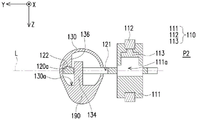
图1A是本发明的第一实施例的笔型折叠鼠标的两个杆体在第一位置时的示意图。图1B是图1A的笔型折叠鼠标的两个杆体在第一位置时的侧视图。图2是本发明的第一实施例的笔型折叠鼠标的两个杆体朝着轴线方向彼此分离于滚轮时的示意图。图3是本发明的第一实施例的笔型折叠鼠标的两个杆体在第二位置时的示意图。FIG. 1A is a schematic diagram of the two rods of the pen-type folding mouse in the first position according to the first embodiment of the present invention. FIG. 1B is a side view of the two rods of the pen-type folding mouse of FIG. 1A when they are in the first position. Fig. 2 is a schematic diagram of the pen-type folding mouse according to the first embodiment of the present invention when the two rods are separated from the scroll wheel toward the axis direction. Fig. 3 is a schematic diagram of the two rods of the pen-type folding mouse in the second position according to the first embodiment of the present invention.
请参考图1A至图3,一种笔型折叠鼠标100包括一滚轮110、两个支撑轴120(图2)、两个杆体130、两个按钮140、一光学感应器150以及一红外线发射器160。滚轮110具有在Y方向上延伸的一轴线L。滚轮110具有一轮框111与一轮圈112。轮圈112环绕轮框111并可相对于轮框111转动。1A to 3, a pen-
如图2所示,两个支撑轴120设置于滚轮110的相对两侧,并分别伸入两个杆体120内。各支撑轴120可自滚轮110的轮框111的相对两侧沿着轴线L延伸,或是平行设置于轴线L旁。两个杆体120位于滚轮110的轮框111的相对两侧,且可运动地配置于两个支撑轴120上,以适于在如图1A的一第一位置P1与如图3的一第二位置P2之间变型。As shown in FIG. 2 , two supporting
如图1B所示,在本实施例中,两个杆体120包括两个外表面131及邻近滚轮110的两个第一端面132。当两个杆体120在第一位置P1时,两个第一端面132会分别靠近并贴合于滚轮110的轮框111的相对两侧。两个按钮140分别设置在两个杆体120的两外表面131上。光学感应器150位于其中一个杆体120的外表面131上。红外线发射器160位于其中一个杆体120在远离滚轮110的一第二端面133上。当然,在其他实施例中,光学感应器150与红外线发射器160也可以位于同一个杆体120上。As shown in FIG. 1B , in this embodiment, the two
在本实施例中,具有红外线发射器160的杆体120内具有一电路板170,而另一个杆体120内具有一电池180(电路板170与电池180皆以虚线绘示)与电池180的一充电口181(如图3所示)。电路板170与光学感应器150、两个按钮140、红外线发射器160以及下文将提到的各种感应机构彼此电性连接,并由电池180供电。并且,电路板170可根据设计上的需求而赋予笔型折叠鼠标100在不同状态下的功效。In this embodiment, the
以下描述本发明的第一实施例的笔型折叠鼠标100的两个杆体130由第一位置P1(图1A)作动至第二位置P2(图3)的过程。请参考图1A,当两个杆体130在第一位置P1时,两个第一端面132朝向滚轮110的轮框111相对两侧。两个杆体130与滚轮110沿着该轴线L延伸而呈一笔杆型10。The following describes the process of moving the two
在笔型折叠鼠标100为笔杆型10的状态下,图1A的笔型折叠鼠标100可例如是作为一简报笔来使用。电路板170例如是具有一蓝牙模块(未绘示)与其他的硬件装置(例如个人电脑、笔记型电脑、平板电脑等装置,未绘示)进行信号传递,而通过两个按钮140或滚轮110的操作来控制硬件装置内存的简报软件(例如
接着,当笔型折叠鼠标100要变型时,请参考图2,两个杆体130沿着轴线L以相反方向彼此分离,使两个杆体130的第一端面132远离滚轮110,并使连接在两个杆体130与滚轮110之间的两个支撑轴120外露。接着,如图3使两个杆体130的两个外表面131朝向滚轮110的轮框111的相对两侧转动且靠近于彼此。此转动的过程可例如是通过后续将描述的支撑轴120与杆体130之间的作动机构完成。亦或是,在其他实施例中,支撑轴本身为可挠性金属而适于弯折,又或是在一些实施例中,杆体本是可挠性金属。Next, when the pen-
在本实施例中,两个杆体130会因为旋转而沿着X方向沿伸并位于第二位置P2。当两个杆体130在第二位置P2时,两个杆体130、滚轮110、光学感应器150及两个按钮140共同成为一鼠标20,并通过电路板170赋予每个部件不同于笔型折叠鼠标100在第一位置P1时的功能。In this embodiment, the two
举例而言,电路板170可以藉由蓝牙模块(未绘示)与其他的硬件装置(未绘示)进行信号传递。两个按钮140可分别作为鼠标20的一左键21与一右键22。光学感应器150则可成为鼠标20在硬件装置的一显示屏幕上的一游标位置控制器,而滚轮110则可为一般鼠标的滚轮功能,例如提供硬件装置内存的软件在显示屏幕上的页面滑动或切换。For example, the
值得注意的是,为了使本发明的笔型折叠鼠标100在第二位置P2(也就是鼠标20)的状态下能够顺利操作,两个杆体130可包括位于两个外表面131上且邻近于滚轮的两个凸出部190。请参考图1B,各个凸出部190的顶部与轴线L的距离R1大于滚轮110的最外侧的半径R2(在此实施例中是轮圈112的最外侧与轴线L之间的半径)。如此配置使得处在第二位置P2的笔型折叠鼠标100放在平面上时,滚轮110的轮圈112能够悬空而顺利地转动,而不会在轮圈112转动时与平面互相干扰。类似地,杆体130的径向尺寸可大于滚轮110的径向尺寸,同样可使滚轮110的轮圈112能够悬空而顺利地转动。另外,在本实施例中,外表面132为圆柱形的杆体130的表面,但杆体130的形状并不以圆柱形为限。在其他实施例中,杆体可例如是长方体、圆锥等柱体或锥体,本发明并不对此加以限制。It is worth noting that, in order to make the pen-
通过上述的作动原理描述,本发明的笔型折叠鼠标100在第一位置P1与第二位置P2之间切换而具有不同的功效。在第一位置P1时,笔型折叠鼠标100为笔杆型10而方便使用者携带或例如是简报笔。在第二位置时,笔型折叠鼠标100为鼠标20。此种切换机制增加了使用者在使用上与携带上的便利性。Through the description of the above-mentioned operation principle, the pen-
以下将就本发明的笔型折叠鼠标100在第一位置P1与第二位置P2切换过程中的内部机构作动进行描述。The following will describe the operation of the internal mechanism of the pen-
图4A是图1A的笔型折叠鼠标沿着A-A’线段的局部剖视图。图4B是图1A的笔型折叠鼠标沿着B-B’线段的局部剖视图。为清楚描述以及表示,以下将就滚轮110的相对两侧的其中一侧的支撑轴120与杆体130进行描述。Fig. 4A is a partial cross-sectional view of the pen-shaped folding mouse of Fig. 1A along line A-A'. Fig. 4B is a partial cross-sectional view of the pen-shaped folding mouse of Fig. 1A along line B-B'. For clarity of description and representation, the
请参考图1A、图4A与图4B。本发明的第一实施例的笔型折叠鼠标100的各个杆体130分别具有位于杆体130内部的一滑块134、一第一定位部135以及一第二定位部136(图4A)。各个支撑轴120(图3)分别具有一滑槽121与一第一卡合部122。Please refer to FIG. 1A , FIG. 4A and FIG. 4B . Each
如图4B所示,滑块134可以是一柱状结构且设置于杆体130的一内表面130a。滑块134穿设于滑槽121(图4A)中而适于在滑槽121内滑动与转动。第一卡合部122设置于支撑轴120(图3)远离滚轮110的一端部120a上。当杆体130在第一位置P1时,杆体130内的第一定位部135卡合于对应的支撑轴120的第一卡合部122,且滑块134位于滑槽121内的一第一端121a。第一卡合部122例如是凸起的凸块而第一定位部135例如是凹槽而能彼此卡合。As shown in FIG. 4B , the
由于第一卡合部122与第一定位部135对应外型上的圆弧状设计,两者能通过使用者沿着滚轮110的轴线L施加的一作用力而能彼此分离。图5A是图2的笔型折叠鼠标沿着C-C’线段的局部剖视图。图5B是图2的笔型折叠鼠标沿着D-D’线段的局部剖视图。请参考图2、图5A以及图5B,与第一卡合部122分离的杆体130适于通过滑块134沿着滑槽121滑动而和支撑轴120与滚轮110在滚轮110的轴线L(也就是Y方向)上分离。此时,滑块134位于滑槽121的一第二端121b。Due to the arc-shaped design of the first engaging
图6A是图3的笔型折叠鼠标沿着E-E’线段的局部剖视图。图6B是图3的笔型折叠鼠标沿着F-F’线段的局部剖视图。请参考图3、图6A以及图6B。接着,使用者可将杆体130相对于滚轮110旋转90度,滑块134在滑槽121的第二端121b转向,而使杆体130内的第二定位部136卡合于支撑轴120的第一卡合部122,并将本发明的笔型折叠鼠标100固定在第二位置P2,成为一个鼠标20的外观。第二定位部136可例如与第一定位部135以相同的材质与相同的构型而制成,于此不加以赘述。Fig. 6A is a partial cross-sectional view of the pen-shaped folding mouse of Fig. 3 along line E-E'. Fig. 6B is a partial cross-sectional view of the pen-shaped folding mouse of Fig. 3 along the line F-F'. Please refer to FIG. 3 , FIG. 6A and FIG. 6B . Next, the user can rotate the
在其他实施例中,第二定位部与第一定位部可以是凸块,第一卡合部可以是与凸块形状对应的凹槽而能和第二定位部与第一定位部彼此卡合。亦或是,第二定位部与第一定位部可以是磁吸件,第一卡合部可以是受磁吸的材质而受到吸引。亦或是,第一卡合部可以是磁吸件,第二定位部与第一定位部可以是受磁吸的材质而受到吸引。亦或是,第二定位部、第一定位部以及第一卡合部可以皆为磁吸件而在第一位置与第二位置互相吸引。In other embodiments, the second positioning portion and the first positioning portion may be protrusions, and the first engaging portion may be a groove corresponding to the shape of the protrusion so as to engage with the second positioning portion and the first positioning portion. . Alternatively, the second positioning portion and the first positioning portion may be magnetic components, and the first engaging portion may be attracted by a material that is magnetically attracted. Alternatively, the first engaging portion may be a magnetic attraction member, and the second positioning portion and the first positioning portion may be attracted by magnetic materials. Alternatively, the second positioning portion, the first positioning portion, and the first engaging portion may all be magnetic components that attract each other at the first position and the second position.
值得一提的是,如图6A所示,本实施例中的滚轮110的轮框111在截面上为一H字型而在外观上具有一环状沟槽。轮圈112的形状与环状沟槽的形状相配合且适于相对于轮框111转动。轮框111与轮圈112之间可嵌入例如是滚珠(未示出)的辅助滑动结构而使轮圈112的滑动更加顺畅。另外,如图6B所示,在本实施例中,轮框111内具有一容置空间111a。容置空间111a内容纳了一感测总成113并设置于轮圈112内侧。并且,在笔型折叠鼠标100是鼠标20的形态时,感测总成113会靠近使用者的滚动轮圈112的一侧。详细而言,感测总成113可以包括压力感测器与转动感测器,并用以感测轮圈112受到使用者操作时的转动与按压。另外,容置空间111a延伸至轮框111的相对两侧,而提供空间供电路板170与轮框111内的感测总成113之间电性连接的走线(未绘示)通过。然而,为了图示的整齐与易于说明,图4A至图6B并未示出电性连接结构。It is worth mentioning that, as shown in FIG. 6A , the
图7是本发明的第二实施例的笔型折叠鼠标的杆体在第一位置时的局部剖视图。图8是本发明的第二实施例的笔型折叠鼠标的杆体沿着轴线分离于滚轮时的局部剖视图。图9A是本发明的第二实施例的笔型折叠鼠标的杆体在第二位置时的局部剖视图。图9B是图9A的另一视角的局部剖视图。图9C是图9A的本发明的第二实施例的笔型折叠鼠标在第二位置时的俯视图。图7、图8以及图9A的视角分别与图4A、图5A以及图6A的视角相同。图9B的视角与图6B的视角相同。Fig. 7 is a partial cross-sectional view of the rod of the pen-type folding mouse in the first position according to the second embodiment of the present invention. FIG. 8 is a partial cross-sectional view of the pen-shaped folding mouse according to the second embodiment of the present invention when the rod body is separated from the scroll wheel along the axis. 9A is a partial cross-sectional view of the rod of the pen-type folding mouse in the second position according to the second embodiment of the present invention. FIG. 9B is a partial cross-sectional view from another viewing angle of FIG. 9A . FIG. 9C is a top view of the pen-shaped folding mouse of FIG. 9A according to the second embodiment of the present invention at the second position. The viewing angles of FIG. 7 , FIG. 8 , and FIG. 9A are the same as those of FIG. 4A , FIG. 5A , and FIG. 6A . The viewing angle of FIG. 9B is the same as that of FIG. 6B.
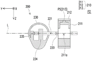
为清楚描述以及表示,以下将就图9C的滚轮210的相对两侧的其中一侧的支撑轴220与杆体230进行描述。另外,本实施例除支撑轴220与杆体230内部的构型不同外,其于构件与外观可和第一实施例相同或相似,于此不加以赘述。For clarity of description and representation, the
请参考图7至图9C。图7至图9C示出本发明的第二实施例的笔型折叠鼠标200在第一位置P1与第二位置P2切换过程中的内部机构作动方式。Please refer to FIG. 7 to FIG. 9C . FIG. 7 to FIG. 9C show the operation mode of the internal mechanism of the pen-
本发明的第二实施例的笔型折叠鼠标200的各个杆体230分别具有位于杆体230内部的一第一定位部235与一滑块234。各个支撑轴220分别具有一第一卡合部222、一第二卡合部223以及一滑槽221。滑块234可以是一柱状结构且设置于杆体230的一内表面230a。滑块234穿设于滑槽221中而适于在滑槽221内滑动与转动。第一卡合部222为凹陷于支撑轴220的一侧面220b上的一个凹槽且第二卡合部223为凹陷于支撑轴220远离滚轮210的端部220a的一个凹槽。Each
当杆体230在第一位置P1时,杆体230内的第一定位部235卡合于对应的支撑轴220的第一卡合部222,且滑块234位于滑槽221内的一第一端221a。杆体230内的第一定位部235例如是凸起的金属弹片且会因受力而变形。When the
由于第一卡合部222与第一定位部235具有对应的圆弧状设计,两者能通过使用者施加的一作用力而能彼此分离。如图8所示,与第一卡合部222分离的杆体230适于通过滑块234沿着滑槽212滑动而和支撑轴220与滚轮210在滚轮210的轴向L(也就是Y方向)上分离。第一定位部235会受到支撑轴220的侧面220b的推抵而被压平并顺着侧面220b滑动,使滑块234滑至滑槽221的第二端221b。Since the first engaging
接着,使用者可将杆体230相对于滚轮210旋转90度,如图9A所示,滑块234可在滑槽221的第二端221b转向。此时第一定位部235顺着第二卡合部223的凹槽形状弹出而使杆体230内的第一定位部235卡合于支撑轴220的第二卡合部223,并将本实施例的笔型折叠鼠标200固定在第二位置P2,成为一个鼠标20(如图3所示)的外观。Then, the user can rotate the
另外,本发明的第二实施例的轮圈212完全覆盖在轮框211的圆柱面且适于相对于轮框211转动。轮框211与轮圈212之间亦可如同嵌入例如是滚珠(未示出)的辅助滑动结构而使轮圈212的滑动更加顺畅。除此之外,轮框211可具有与第一实施例相似或相同的容置空间211a与感测总成213,如图9B所示。In addition, the
值得一提的是,在本实施例中,感测总成213可仅为一压力感测器PS,并且另外在两个杆体230的其中一者上可设置位于外表面231且靠近滚轮210的一转动感测器MS。如图9C所示,当两个杆体在第二位置时,转动感测器MS可例如是在Y方向上与轮圈212相交叠而感测轮圈212的转动行为。同样的,为了图示的整齐与易于说明,图7至图9B并未示出感测总成213与电路板的电性连接结构。It is worth mentioning that, in this embodiment, the
图10是本发明的第三实施例的滑块的示意图。图11A是本发明的第三实施例的笔型折叠鼠标的杆体在第一位置时的局部示意图。图11B是图11A沿着G-G’线段的剖视图。请先参考图10。Fig. 10 is a schematic diagram of a slider according to a third embodiment of the present invention. FIG. 11A is a partial schematic diagram of the rod of the pen-type folding mouse in the first position according to the third embodiment of the present invention. Fig. 11B is a cross-sectional view of Fig. 11A along line G-G'. Please refer to Figure 10 first.
为清楚描述以及表示,以下将就滚轮310的相对两侧的其中一侧的支撑轴320与杆体330进行描述。另外,本实施例除支撑轴320与杆体330内部的构型不同外,其于构件与外观可和第一实施例相同或相似,于此不加以赘述。For clarity of description and representation, the
本发明第三实施例的滑块334是一圆柱状结构且凸出于杆体330的一内表面330a。滑块334具有一第一定位部334a与一第二定位部334b。第一定位部334a相对于内表面330a位在一第一高度H1上且沿X方向延伸。第二定位部334b相对于内表面330a位在一第二高度H2上且沿Y方向延伸,且第一高度H1大于第二高度H2而使第一定位部334a与第二定位部334b在Z方向上错开。第一定位部334a与第二定位部334b为相同或相似的弹片结构,适于受到推抵而变形。The
请参考图11A与图11B。图11A的视角与图4A的视角相同。支撑轴320具有一滑槽321、一第一定位穴322(图13A)以及一第二定位穴323。第一定位穴322与第二定位穴323分别具有相对于支撑轴320的一顶面320c在Z方向上具有不同的深度,且在组装上第一定位部334a的第一高度H1能对应到第一定位穴322而第二定位部334b的第二高度H2能对应到第二定位穴323。第一定位穴322靠近于滑槽321的一第一端321a并连通于滑槽321。第二定位穴323靠近于滑槽321的一第二端321b并连通于滑槽321(由图12A清楚示出)。滑块334适于在滑槽321内滑动及转动。Please refer to FIG. 11A and FIG. 11B . The viewing angle of FIG. 11A is the same as that of FIG. 4A . The supporting
当两杆体330在第一位置P1时,滑块334位在滑槽321的第一端321a且凸出的第一定位部334a卡合于对应其形状的第一定位穴322。When the two
图12A是本发明的第三实施例的笔型折叠鼠标的杆体朝着轴线方向分离于滚轮时的局部示意图。图12B是图12A沿着H-H’线段的剖视图。请参考图12A与图12B。其中图12A的视角与图5A的视角相同。当使用者操作使滑块324由滑槽321的第一端321a往第二端321b移动时,第一定位部334a会由于滑槽321的内壁面的在X方向上的宽度相较于第一定位穴322在X方向上的宽度较窄,而受到挤压以使滑块334得以在滑槽321内往第二端321b滑动。12A is a partial schematic diagram of the pen-shaped folding mouse according to the third embodiment of the present invention when the rod body is separated from the scroll wheel toward the axis direction. Fig. 12B is a cross-sectional view along line H-H' of Fig. 12A. Please refer to FIG. 12A and FIG. 12B . The viewing angle in FIG. 12A is the same as that in FIG. 5A . When the user operates the slider 324 to move from the
图13A是本发明的第三实施例的笔型折叠鼠标的在第二位置时的局部示意图。图13B是图13A沿着I-I’线段的剖视图。请参考图13A与图13B。图13A的视角与图6A的视角相同。接着,使用者可将杆体330相对于滚轮310旋转90度,如图13A与图13B所示,滑块334可在滑槽321的第二端321b转向使两个杆体330位于第二位置P2。此时第二定位部334b吻合第二卡合穴323的凹槽形状,并将本实施例的笔型折叠鼠标300固定在第二位置P2。FIG. 13A is a partial schematic view of the pen-type folding mouse in the second position according to the third embodiment of the present invention. Fig. 13B is a cross-sectional view of Fig. 13A along line I-I'. Please refer to FIG. 13A and FIG. 13B . The viewing angle of FIG. 13A is the same as that of FIG. 6A. Next, the user can rotate the
图14是本发明的第四实施例的笔型折叠鼠标在第二位置时的俯视图。请参考图14。在本实施例中,笔型折叠鼠标400的支撑轴420可具有类似于前述第一至第三实施例的滑槽,但不具有任何的卡合机制。取而代之,在两个杆体430上分别设置第一磁吸件FM与第二磁吸件SM。各第一磁吸件FM与对应的第二磁吸件SM位于对应的杆体430的相对两个端部。当两个杆体430在如同图1A的第一位置P1时,两个杆体430的两个第一磁吸件FM靠近于滚轮410且彼此吸引以维持如同图1A的笔杆型10。当两个杆体430在第二位置P2时,两个杆体430的两个第二磁吸件SM彼此吸引以维持如同图3的鼠标20的形状。Fig. 14 is a top view of the pen-shaped folding mouse in the second position according to the fourth embodiment of the present invention. Please refer to Figure 14. In this embodiment, the
以下将针对滚轮内的感测总成与电路板之间的电性连接进行说明。The electrical connection between the sensing assembly in the roller and the circuit board will be described below.
图15是本发明的第五实施例的滚轮与支撑轴的局部示意图。为清楚描述以及表示,以下将就滚轮510的相对两侧的其中一侧的支撑轴520进行描述。请参考图15。在本实施例中,一软排线501贴附于支撑轴520上,且软排线501的一端的一第一接口501a穿入滚轮510中与感测总成513电性连接,而软排线501的另一端的一第二接口501b可伸入如图1A的杆体130而连接于电路板170。Fig. 15 is a partial schematic diagram of a roller and a supporting shaft according to a fifth embodiment of the present invention. For clarity of description and representation, the
软排线501穿入滚轮510的第一接口501a可类似于穿入第一实施例的容置空间111a或第二实施例的容置空间211a,且滚轮510、支撑轴520、以及感测总成513可以第一实施例至第四实施例中类似的对应构件替换。举例而言,感测总成513可以如第二实施例的压力感测器213a。软排线501贴附于支撑轴220且一端穿过容置空间211a与压力感测器213a连接,而另一端则与位于杆体230内的电路板连接。The
图16是本发明的第六实施例的滚轮、支撑轴以及杆体的局部剖示图。为清楚描述以及表示,以下将就滚轮的相对两侧的其中一侧的支撑轴与杆体进行描述。请参考图16。杆体630更包括位于内部且通过电线电性连接于电路板670的两个金属片601。具有两个金属片601的杆体630所对应的支撑轴620包括电性连接至感测总成613的两条导体621。两条导体621通过例如是电线与滚轮610的壳体611的容置空间611a内的感测总成613电性连接。两金属片601接触对应的两条导体621,以将感测总成613电性连接至电路板670。滚轮610的轮框611与其容置空间611a、轮圈612以及感测总成613可类似于或相同于第一实施例的态样而设置。Fig. 16 is a partial sectional view of the roller, the support shaft and the rod body of the sixth embodiment of the present invention. For clarity of description and representation, the support shaft and rod body on one of the opposite two sides of the roller will be described below. Please refer to Figure 16. The
综合上述,本发明的笔型折叠鼠标的两杆体可在第一位置与第二位置之间变型而呈笔杆型或鼠标,并且在笔杆型时可具备不同于鼠标时的功能。整合多种功能性而减少了使用者需要同时携带多种装置的负担。同时,使用者在不使用鼠标时,可将笔型折叠鼠标变型为笔杆型,方便使用者携带。To sum up the above, the two rods of the pen-type folding mouse of the present invention can be transformed between the first position and the second position to form a pen holder or a mouse, and the function of the pen holder can be different from that of a mouse. Integrating multiple functions reduces the burden on the user to carry multiple devices at the same time. At the same time, when the user is not using the mouse, the pen-type folding mouse can be transformed into a pen holder type, which is convenient for the user to carry.
虽然本发明已以实施例揭露如上,然其并非用以限定本发明,任何所属技术领域中具有通常知识者,在不脱离本发明的精神和范围内,当可作些许的更动与润饰,故本发明的保护范围当视后附的发明专利范围所界定者为准。Although the present invention has been disclosed as above with the embodiments, it is not intended to limit the present invention. Anyone with ordinary knowledge in the technical field can make some changes and modifications without departing from the spirit and scope of the present invention. Therefore, the scope of protection of the present invention shall be as defined by the scope of the appended patent for invention.
Claims (14)
Priority Applications (1)
| Application Number | Priority Date | Filing Date | Title |
|---|---|---|---|
| CN201811625703.8A CN111381692B (en) | 2018-12-28 | 2018-12-28 | Pen type folding mouse |
Applications Claiming Priority (1)
| Application Number | Priority Date | Filing Date | Title |
|---|---|---|---|
| CN201811625703.8A CN111381692B (en) | 2018-12-28 | 2018-12-28 | Pen type folding mouse |
Publications (2)
| Publication Number | Publication Date |
|---|---|
| CN111381692A CN111381692A (en) | 2020-07-07 |
| CN111381692B true CN111381692B (en) | 2023-02-28 |
Family
ID=71216428
Family Applications (1)
| Application Number | Title | Priority Date | Filing Date |
|---|---|---|---|
| CN201811625703.8A Active CN111381692B (en) | 2018-12-28 | 2018-12-28 | Pen type folding mouse |
Country Status (1)
| Country | Link |
|---|---|
| CN (1) | CN111381692B (en) |
Families Citing this family (1)
| Publication number | Priority date | Publication date | Assignee | Title |
|---|---|---|---|---|
| CN116149496B (en) * | 2022-12-15 | 2025-12-19 | 深圳市亿道数码技术有限公司 | Touch pad and notebook computer |
Citations (11)
| Publication number | Priority date | Publication date | Assignee | Title |
|---|---|---|---|---|
| TWM258359U (en) * | 2004-05-28 | 2005-03-01 | Partner Tech Corp | Pen mouse with fast function keys |
| WO2006049275A1 (en) * | 2004-11-05 | 2006-05-11 | Ippey Hirano | Coordinate pointing system and method |
| TW200807278A (en) * | 2006-07-28 | 2008-02-01 | Hao-Wen Chen | Combined pen device with cursor unit |
| CN201174104Y (en) * | 2008-04-11 | 2008-12-31 | 薛显诗 | Collapsible deformation mouse |
| US7733326B1 (en) * | 2004-08-02 | 2010-06-08 | Prakash Adiseshan | Combination mouse, pen-input and pen-computer device |
| CN201654703U (en) * | 2009-11-30 | 2010-11-24 | 英业达股份有限公司 | Deformable mouse |
| TWM400613U (en) * | 2010-09-10 | 2011-03-21 | Cheng-Wei Wang | Structural improvement of mouse |
| CN104199568A (en) * | 2014-10-03 | 2014-12-10 | 邓乔波 | Pen-shaped photoelectric mouse |
| CN204808241U (en) * | 2015-06-12 | 2015-11-25 | 清华大学 | Collapsible mouse |
| CN107272928A (en) * | 2017-07-24 | 2017-10-20 | 广州市加简派电子科技有限公司 | A kind of new mouse |
| CN108357242A (en) * | 2018-04-10 | 2018-08-03 | 苏鹏辉 | A kind of bent handset pen |
Family Cites Families (4)
| Publication number | Priority date | Publication date | Assignee | Title |
|---|---|---|---|---|
| TWI228678B (en) * | 2003-12-02 | 2005-03-01 | Benq Corp | Dual mode computer mouse |
| GB2411452C (en) * | 2004-08-06 | 2008-03-17 | Simon Richard Daniel | Flat and collapsible mouse |
| TWI478011B (en) * | 2011-06-29 | 2015-03-21 | Giga Byte Tech Co Ltd | Pointing device |
| CN108345396B (en) * | 2017-01-25 | 2021-06-04 | 禾伸堂企业股份有限公司 | Touch pen with magnetic induction wheel and operation method thereof |
-
2018
- 2018-12-28 CN CN201811625703.8A patent/CN111381692B/en active Active
Patent Citations (11)
| Publication number | Priority date | Publication date | Assignee | Title |
|---|---|---|---|---|
| TWM258359U (en) * | 2004-05-28 | 2005-03-01 | Partner Tech Corp | Pen mouse with fast function keys |
| US7733326B1 (en) * | 2004-08-02 | 2010-06-08 | Prakash Adiseshan | Combination mouse, pen-input and pen-computer device |
| WO2006049275A1 (en) * | 2004-11-05 | 2006-05-11 | Ippey Hirano | Coordinate pointing system and method |
| TW200807278A (en) * | 2006-07-28 | 2008-02-01 | Hao-Wen Chen | Combined pen device with cursor unit |
| CN201174104Y (en) * | 2008-04-11 | 2008-12-31 | 薛显诗 | Collapsible deformation mouse |
| CN201654703U (en) * | 2009-11-30 | 2010-11-24 | 英业达股份有限公司 | Deformable mouse |
| TWM400613U (en) * | 2010-09-10 | 2011-03-21 | Cheng-Wei Wang | Structural improvement of mouse |
| CN104199568A (en) * | 2014-10-03 | 2014-12-10 | 邓乔波 | Pen-shaped photoelectric mouse |
| CN204808241U (en) * | 2015-06-12 | 2015-11-25 | 清华大学 | Collapsible mouse |
| CN107272928A (en) * | 2017-07-24 | 2017-10-20 | 广州市加简派电子科技有限公司 | A kind of new mouse |
| CN108357242A (en) * | 2018-04-10 | 2018-08-03 | 苏鹏辉 | A kind of bent handset pen |
Also Published As
| Publication number | Publication date |
|---|---|
| CN111381692A (en) | 2020-07-07 |
Similar Documents
| Publication | Publication Date | Title |
|---|---|---|
| CN104656802B (en) | Fixing mechanism and external electronic device thereof | |
| US9703401B2 (en) | Portable electronic device and miniaturization rechargeable capacitive stylus thereof | |
| US20120146960A1 (en) | Touch pen | |
| CN103914104B (en) | Portable electronic device | |
| CN103034382A (en) | Waterproof housing of digital device with capacitive touch screen and actuating mechanism thereof | |
| US20150261382A1 (en) | Touch control system | |
| CN111258377A (en) | keyboard device | |
| US11388275B2 (en) | Electronic device and camera movement assembly | |
| US9606642B2 (en) | Portable electronic device and miniaturization rechargeable capacitive stylus thereof | |
| CN107924159A (en) | Electronic equipment | |
| US20140321043A1 (en) | Supporting structure and electronic device using the same | |
| US11385688B2 (en) | Electronic apparatus | |
| CN111381692B (en) | Pen type folding mouse | |
| CN106200775B (en) | Charging module and portable electronic device with same | |
| TWI705358B (en) | Pen-shaped folding mouse | |
| US11609648B1 (en) | Stylus pen | |
| KR102732900B1 (en) | Multi foldable electronic device | |
| CN116069177A (en) | Touch control pen | |
| CN109696967A (en) | The person's handwriting of wiping arrangement, touch-control system and touch-control system wipes method off | |
| US20150212604A1 (en) | Touch pen having signal cable | |
| CN217468856U (en) | Electronic device, electronic pen and terminal equipment | |
| TWI752430B (en) | Mouse | |
| US20210223874A1 (en) | Touch pen | |
| CN107835973A (en) | Input device and electronic device for receiving signal from input device | |
| TWM655714U (en) | Input device |
Legal Events
| Date | Code | Title | Description |
|---|---|---|---|
| PB01 | Publication | ||
| PB01 | Publication | ||
| SE01 | Entry into force of request for substantive examination | ||
| SE01 | Entry into force of request for substantive examination | ||
| GR01 | Patent grant | ||
| GR01 | Patent grant |