WO2025024750A2 - Assessing nitrogenase proteins in rhizosphere to infer microbial functioning - Google Patents
Assessing nitrogenase proteins in rhizosphere to infer microbial functioning Download PDFInfo
- Publication number
- WO2025024750A2 WO2025024750A2 PCT/US2024/039701 US2024039701W WO2025024750A2 WO 2025024750 A2 WO2025024750 A2 WO 2025024750A2 US 2024039701 W US2024039701 W US 2024039701W WO 2025024750 A2 WO2025024750 A2 WO 2025024750A2
- Authority
- WO
- WIPO (PCT)
- Prior art keywords
- nitrogen
- plant
- plants
- sample
- polypeptide
- Prior art date
- Legal status (The legal status is an assumption and is not a legal conclusion. Google has not performed a legal analysis and makes no representation as to the accuracy of the status listed.)
- Pending
Links
Classifications
-
- G—PHYSICS
- G01—MEASURING; TESTING
- G01N—INVESTIGATING OR ANALYSING MATERIALS BY DETERMINING THEIR CHEMICAL OR PHYSICAL PROPERTIES
- G01N33/00—Investigating or analysing materials by specific methods not covered by groups G01N1/00 - G01N31/00
- G01N33/48—Biological material, e.g. blood, urine; Haemocytometers
- G01N33/50—Chemical analysis of biological material, e.g. blood, urine; Testing involving biospecific ligand binding methods; Immunological testing
- G01N33/53—Immunoassay; Biospecific binding assay; Materials therefor
- G01N33/543—Immunoassay; Biospecific binding assay; Materials therefor with an insoluble carrier for immobilising immunochemicals
- G01N33/54366—Apparatus specially adapted for solid-phase testing
- G01N33/54386—Analytical elements
- G01N33/54387—Immunochromatographic test strips
- G01N33/54388—Immunochromatographic test strips based on lateral flow
-
- A—HUMAN NECESSITIES
- A01—AGRICULTURE; FORESTRY; ANIMAL HUSBANDRY; HUNTING; TRAPPING; FISHING
- A01N—PRESERVATION OF BODIES OF HUMANS OR ANIMALS OR PLANTS OR PARTS THEREOF; BIOCIDES, e.g. AS DISINFECTANTS, AS PESTICIDES OR AS HERBICIDES; PEST REPELLANTS OR ATTRACTANTS; PLANT GROWTH REGULATORS
- A01N63/00—Biocides, pest repellants or attractants, or plant growth regulators containing microorganisms, viruses, microbial fungi, animals or substances produced by, or obtained from, microorganisms, viruses, microbial fungi or animals, e.g. enzymes or fermentates
- A01N63/20—Bacteria; Substances produced thereby or obtained therefrom
-
- C—CHEMISTRY; METALLURGY
- C07—ORGANIC CHEMISTRY
- C07K—PEPTIDES
- C07K14/00—Peptides having more than 20 amino acids; Gastrins; Somatostatins; Melanotropins; Derivatives thereof
- C07K14/195—Peptides having more than 20 amino acids; Gastrins; Somatostatins; Melanotropins; Derivatives thereof from bacteria
-
- C—CHEMISTRY; METALLURGY
- C07—ORGANIC CHEMISTRY
- C07K—PEPTIDES
- C07K14/00—Peptides having more than 20 amino acids; Gastrins; Somatostatins; Melanotropins; Derivatives thereof
- C07K14/195—Peptides having more than 20 amino acids; Gastrins; Somatostatins; Melanotropins; Derivatives thereof from bacteria
- C07K14/24—Peptides having more than 20 amino acids; Gastrins; Somatostatins; Melanotropins; Derivatives thereof from bacteria from Enterobacteriaceae (F), e.g. Citrobacter, Serratia, Proteus, Providencia, Morganella, Yersinia
- C07K14/26—Klebsiella (G)
-
- C—CHEMISTRY; METALLURGY
- C07—ORGANIC CHEMISTRY
- C07K—PEPTIDES
- C07K14/00—Peptides having more than 20 amino acids; Gastrins; Somatostatins; Melanotropins; Derivatives thereof
- C07K14/415—Peptides having more than 20 amino acids; Gastrins; Somatostatins; Melanotropins; Derivatives thereof from plants
-
- C—CHEMISTRY; METALLURGY
- C12—BIOCHEMISTRY; BEER; SPIRITS; WINE; VINEGAR; MICROBIOLOGY; ENZYMOLOGY; MUTATION OR GENETIC ENGINEERING
- C12N—MICROORGANISMS OR ENZYMES; COMPOSITIONS THEREOF; PROPAGATING, PRESERVING, OR MAINTAINING MICROORGANISMS; MUTATION OR GENETIC ENGINEERING; CULTURE MEDIA
- C12N1/00—Microorganisms; Compositions thereof; Processes of propagating, maintaining or preserving microorganisms or compositions thereof; Processes of preparing or isolating a composition containing a microorganism; Culture media therefor
- C12N1/20—Bacteria; Culture media therefor
-
- C—CHEMISTRY; METALLURGY
- C12—BIOCHEMISTRY; BEER; SPIRITS; WINE; VINEGAR; MICROBIOLOGY; ENZYMOLOGY; MUTATION OR GENETIC ENGINEERING
- C12N—MICROORGANISMS OR ENZYMES; COMPOSITIONS THEREOF; PROPAGATING, PRESERVING, OR MAINTAINING MICROORGANISMS; MUTATION OR GENETIC ENGINEERING; CULTURE MEDIA
- C12N15/00—Mutation or genetic engineering; DNA or RNA concerning genetic engineering, vectors, e.g. plasmids, or their isolation, preparation or purification; Use of hosts therefor
- C12N15/09—Recombinant DNA-technology
- C12N15/11—DNA or RNA fragments; Modified forms thereof; Non-coding nucleic acids having a biological activity
- C12N15/52—Genes encoding for enzymes or proenzymes
-
- C—CHEMISTRY; METALLURGY
- C12—BIOCHEMISTRY; BEER; SPIRITS; WINE; VINEGAR; MICROBIOLOGY; ENZYMOLOGY; MUTATION OR GENETIC ENGINEERING
- C12N—MICROORGANISMS OR ENZYMES; COMPOSITIONS THEREOF; PROPAGATING, PRESERVING, OR MAINTAINING MICROORGANISMS; MUTATION OR GENETIC ENGINEERING; CULTURE MEDIA
- C12N9/00—Enzymes; Proenzymes; Compositions thereof; Processes for preparing, activating, inhibiting, separating or purifying enzymes
- C12N9/0004—Oxidoreductases (1.)
- C12N9/0095—Oxidoreductases (1.) acting on iron-sulfur proteins as donor (1.18)
-
- A—HUMAN NECESSITIES
- A01—AGRICULTURE; FORESTRY; ANIMAL HUSBANDRY; HUNTING; TRAPPING; FISHING
- A01C—PLANTING; SOWING; FERTILISING
- A01C21/00—Methods of fertilising, sowing or planting
- A01C21/007—Determining fertilization requirements
-
- C—CHEMISTRY; METALLURGY
- C12—BIOCHEMISTRY; BEER; SPIRITS; WINE; VINEGAR; MICROBIOLOGY; ENZYMOLOGY; MUTATION OR GENETIC ENGINEERING
- C12R—INDEXING SCHEME ASSOCIATED WITH SUBCLASSES C12C - C12Q, RELATING TO MICROORGANISMS
- C12R2001/00—Microorganisms ; Processes using microorganisms
- C12R2001/01—Bacteria or Actinomycetales ; using bacteria or Actinomycetales
-
- C—CHEMISTRY; METALLURGY
- C12—BIOCHEMISTRY; BEER; SPIRITS; WINE; VINEGAR; MICROBIOLOGY; ENZYMOLOGY; MUTATION OR GENETIC ENGINEERING
- C12R—INDEXING SCHEME ASSOCIATED WITH SUBCLASSES C12C - C12Q, RELATING TO MICROORGANISMS
- C12R2001/00—Microorganisms ; Processes using microorganisms
- C12R2001/01—Bacteria or Actinomycetales ; using bacteria or Actinomycetales
- C12R2001/22—Klebsiella
Definitions
- TECHNICAL FIELD This document relates to agriculture and agricultural practices, and more particularly to determining whether a microbe is fixing nitrogen.
- the present invention provides a method for determining the presence or absence of a polypeptide involved in nitrogen fixation in a rhizosphere of a plant using an assay with a reactive agent, such as a lateral flow assay.
- BACKGROUND Biological nitrogen fixation is a process by which plant-associated microbes provide nitrogen to host plants.
- Nitrogen is an important nutrient that influences plant growth.
- nitrogen is present in both amino acids and chlorophyll pigments, and a wide variety of biological processes, including plant-based protein synthesis and photosynthesis, depend on the availability of nitrogen. When adequate soluble nitrogen is not available to a plant, vegetative growth may be retarded and fruit production attenuated.
- fixation of atmospheric nitrogen gas to yield soluble ammonia occurs via naturally-occurring microbes.
- Significant research activity is currently directed to engineering improved microbes that enhance reductive conversion of atmospheric nitrogen to ammonia as an alternative to prior practices involving synthetic nitrogen fertilizer.
- An important aspect of this activity is measurement of nitrogen fixation of these microbes in the field to confirm their nitrogen fixation performance.
- microbes e.g., genetically engineered microbes
- Such real-time measurements can be used, for example, by agricultural crop growers to obtain real-time information about nitrogen management of the crop.
- acetylene reduction assays can be time- consuming and are best performed in a lab environment, outside of the field context.
- the methods can be performed using a lateral flow assay to determine the presence or absence of a polypeptide involved in nitrogen fixation in a sample of soil from the rhizosphere of a plant.
- the presence of a polypeptide involved in nitrogen fixation indicates that nitrogen fixation is occurring.
- the ease of use, long shelf life, and lack of refrigeration required for storage makes lateral flow assays advantageous for use in the field for real-time analysis of nitrogen fixation.
- determining the presence or absence of a polypeptide involved in nitrogen fixation in a rhizosphere of a non-leguminous plant that include: (a) contacting a sample of soil from the rhizosphere with a lysis buffer, thereby producing a solution; (b) contacting the solution with a sample-receiving zone of a substrate, wherein the substrate further comprises a detection zone comprising a reactive agent that, directly or indirectly, produces a signal based on the presence or absence of the polypeptide involved in nitrogen fixation once the solution contacts the detection zone; (c) detecting the signal produced by the reactive agent (e.g., in about 5 seconds to about 1 hour) after the solution contacts the detection zone; and (d) determining the presence or absence of the polypeptide involved in nitrogen fixation in the solution based on detection of the signal.
- a detection zone comprising a reactive agent that, directly or indirectly, produces a signal based on the presence or absence of the polypeptide involved in nitrogen fixation once the solution contacts the detection zone
- the polypeptide involved in nitrogen fixation is selected from the group consisting of: nifH, nifD, and nifK. In some embodiments of any of the methods described herein, the polypeptide involved in nitrogen fixation is nifH. In some embodiments of any of the methods described herein, the polypeptide involved in nitrogen fixation is nifD. In some embodiments of any of the methods described herein, the polypeptide involved in nitrogen fixation is nifK. In some embodiments of any of the methods described herein, the reactive agent is an antibody or antigen-binding fragment of an antibody. In some embodiments of any of the methods described herein, the antibody is a monoclonal antibody.
- the antibody is a polyclonal antibody. Some embodiments of any of the methods described herein further include: comparing the detected signal to a signal produced using a reference sample. In some embodiments of any of the methods described herein, the signal is a visual signal. In some embodiments of any of the methods described herein, the solution flows from the sample-receiving zone of the substrate to the detection zone of the substrate via capillary flow. In some embodiments of any of the methods described herein, step (c) comprises detecting the signal produced by the reactive agent about 5 seconds to about 1 hour (e.g., about 30 seconds to about 1 hour) after the solution contacts the detection zone.
- step (c) comprises detecting the signal produced by the reactive agent about 1 minute to about 20 minutes after the solution contacts the detection zone.
- the lysis buffer comprises water, at least one detergent, and one or more of a salt, an organic acid, a base, a chelating agent, an enzyme, a protease inhibitor, a sugar, and a reducing agent.
- the lysis buffer comprises water, at least one detergent, and at least one salt.
- the lysis buffer comprises one or more of phenol, sodium dodecyl sulfate, and sodium hydroxide.
- determining the amount of nitrogen in the rhizosphere comprises determining the amount of one or more of NH4 + , NH3, urea, NO3, and NO2 in the rhizosphere.
- determining the nitrogen status of the non-leguminous plant comprises determining the nitrogen status of the non-leguminous plant.
- determining the nitrogen status of the non-leguminous plant comprises: (a) determining the chlorophyll content of the non-leguminous plant; (b) determining the biomass of the non-leguminous plant; (c) normalizing the determined biomass and the determined chlorophyll content for the plant; and (d) determining plant nitrogen status of the plant using the normalized chlorophyll content (CC) and the normalized biomass (PB) of the plant.
- the chlorophyll content is determined using a chlorophyll meter.
- the biomass is determined using a digital scale.
- ⁇ is 0.80.
- ⁇ is 0.20.
- ⁇ is 0.80 and ⁇ is 0.20.
- the non-leguminous plant is selected from the group consisting of: maize (e.g., sweet corn), rice, wheat, barley, sorghum, millet, oats, rye, triticale, buckwheat, sugar cane, onions, tomatoes, strawberries, and asparagus.
- maize e.g., sweet corn
- rice e.g., rice
- wheat barley
- sorghum e.g., sorghum
- millet oats
- rye e.g., triticale
- buckwheat buckwheat
- sugar cane onions, tomatoes, strawberries, and asparagus.
- one or more of the non-leguminous plant, the rhizosphere of the non-leguminous plant, soil in which the non- leguminous plant was cultivated, or a seed from which the non-leguminous plant was grown was previously contacted with one or more bacteria.
- the one or more bacteria are a genetically engineered bacterium comprising a genetic variation in a nitrogen fixation gene or a nitrogen- assimilation gene.
- the one or more bacteria are of a genus independently selected from Kosakonia, Rahnella, Klebsiella, Paenibacillus, Paraburkholderia, and Herbaspirillum.
- the one or more bacteria are of a species indepedently selected from: Kosakonia sacchari, Rahnella aquatilis, Klebsiella variicola, Paenibacillus polymyxa, Paraburkholderia tropica, and Herbaspirillum aquaticum.
- the one or more bacteria comprise at least one strain selected from a group consisting of Klebsiella variicola and Kosakonia sacchari.
- the one or more bacteria comprise a Klebsiella variicola strain.
- the one or more bacteria comprise a Kosakonia sacchari strain. In some embodiments, the one or more bacteria comprise a combination of a Klebsiella variicola strain and a Kosakonia sacchari strain. In some embodiments of any of the methods described herein, the presence of the polypeptide involved in nitrogen fixation in the solution is determined in step (d). In some embodiments of any of the methods described herein, the absence of the polypeptide involved in nitrogen fixation in the solution is determined in step (d).
- any of the methods described herein further include: applying a composition comprising one or more bacteria to one or more of the non-leguminous plant to the rhizosphere of the non-leguminous plant, to the soil in which the non-leguminous plant is cultivated or to the surface of the seed of the non-leguminous plant.
- the one or more bacteria are a genetically engineered bacterium comprising a genetic variation in a nitrogen fixation gene or a nitrogen-assimilation gene.
- the one or more genetically engineered bacteria are of a genus independently selected from Kosakonia, Rahnella, Klebsiella, Paenibacillus, Paraburkholderia, and Herbaspirillum.
- the one or more bacteria are of a species independently selected from: Kosakonia sacchari, Rahnella aquatilis, Klebsiella variicola, Paenibacillus polymyxa, Paraburkholderia tropica, and Herbaspirillum aquaticum.
- the one or more bacteria comprise at least one strain selected from a group consisting of Klebsiella variicola and Kosakonia sacchari. In some embodiments of any of the methods described herein, the one or more bacteria comprise the strains of Klebsiella variicola. In some embodiments of any of the methods described herein, the one or more bacteria comprise at least one strain selected from Klebsiella variicola and Kosakonia sacchari. In some embodiments of any of the methods described herein, the one or more bacteria comprise a Kosakonia sacchari strain. In some embodiments, the one or more bacteria comprise a combination of a Klebsiella variicola strain and a Kosakonia sacchari strain.
- LFA lateral flow assay
- the LFA system includes: (a) a cartridge configured to hold a substrate; and (b) a substrate comprising a sample-receiving zone and a detection zone, wherein the detection zone comprises a reactive agent that produces a signal based on the presence or absence of a nitrogen fixation polypeptide involved in nitrogen fixation in a solution contacted with the sample-receiving zone of the substrate.
- the polypeptide involved in nitrogen fixation is selected from the group consisting of: nifH, nifD, and nifK.
- the polypeptide involved in nitrogen fixation is nifH.
- the polypeptide involved in nitrogen fixation is nifD. In some embodiments of any of the lateral flow assay systems described herein, the polypeptide involved in nitrogen fixation is nifK. In some embodiments of any of the lateral flow assay systems described herein, the reactive agent is an antibody or antigen-binding fragment of an antibody. In some embodiments of any of the lateral flow assay systems described herein, the antibody is a monoclonal antibody. In some embodiments of any of the lateral flow assay systems described herein, the antibody is a polyclonal antibody.
- kits that include: (a) one or more lateral flow assay system(s) described herein; and (b) instructions for using the lateral flow assay system to determine the presence or absence of a polypeptide involved in nitrogen fixation in a rhizosphere of a non-leguminous plant.
- the kit comprises two or more lateral flow assay systems.
- the kit further comprises a container.
- the container comprises a volume of lysis buffer. In some embodiments of any of the kits described herein, the kit further comprises a pipette or dropper.
- a and “an” and “the” and similar referents in the context of describing the disclosure are to be construed to cover both the singular and the plural, unless otherwise indicated herein or clearly contradicted by context.
- the terms “comprising,” “having,” “including,” and “containing” are to be construed as open-ended terms (i.e., meaning “including, but not limited to,”) unless otherwise noted.
- the term “about” is used synonymously with the term “approximately.”
- the use of the term “about” with regard to an amount indicates that values slightly outside the cited values, e.g., plus or minus 0.1% to 10%.
- “about” refers to ⁇ 10%, ⁇ 5%, ⁇ 2%, ⁇ 1%, ⁇ 0.5%, or ⁇ 0.1% of an indicated value or range of values.
- plant can include plant parts, tissue, leaves, roots, root hairs, rhizomes, stems, seeds, ovules, pollen, flowers, fruit, etc.
- the terms “microorganism” or “microbe” should be taken broadly.
- determining encompasses a wide variety of actions and, therefore, “determining” can include calculating, computing, processing, deriving, investigating, looking up (e.g., looking up in a table, a database or another data structure), ascertaining and the like. “Determining” also can include receiving (e.g., receiving information), accessing (e.g., accessing data in a memory) and the like. “Determining” further can include resolving, selecting, choosing, establishing and the like.
- Determining can also include measuring a value.
- the phrase “based on” does not mean “based only on,” unless expressly specified otherwise. In other words, the phrase “based on” describes both “based only on” and “based at least on.” No language in the specification should be construed as indicating any non-claimed element as essential to the practice of the disclosure. Unless otherwise defined, all technical and scientific terms used herein have the same meaning as commonly understood by one of ordinary skill in the art to which this disclosure belongs. Although methods and materials similar or equivalent to those described herein can be used in the practice or testing of the subject matter herein, suitable methods and materials are described below. All publications, patent applications, patents, and other references mentioned herein are incorporated by reference in their entirety.
- FIGs. 1A-1C are exemplary schematics of lateral flow assays used to detect a polypeptide involved in nitrogen fixation.
- FIGs. 1D and 1E are exemplary schematics of test line configurations (bottom panel) and positive test read-outs (top panel).
- FIG. 1D shows, in the bottom panel, a reactive agent immobilized to the substrate and bound directly to a signal molecule when the target polypeptide (TP) is not present in a competitive test assay (bottom right).
- TP target polypeptide
- bottom right the target polypeptide preferentially binds to the reactive agent, which then releases the signal molecule into the solution that is carried away by the capillary action (bottom left). This results in a positive test read-out of a lack of a test line (dotted test line in top panel). A control line is optional.
- FIG. 1E shows, in the bottom panel, a reactive agent immobilized to a substrate, bound to a target polypeptide (TP), which is also bound at a different location on the TP, to a second reactive agent that includes or is bound to a signal molecule.
- TP target polypeptide
- FIGs.2A-2F are graphs of various plant measurements for maize plants treated with a grower standard nitrogen fertilization or treated with nitrogen fixing microbial(s) and a reduction of 35 lbs of synthetic nitrogen (N).
- FIG.2A is a graph of plant fresh weight in lbs per plant for treated maize plants.
- FIG.2B is a graph of leaf chlorophyll concentration in ⁇ mol per m 2 for treated maize plants.
- FIG.2C is a graph of plant nitrogen update in lbs of nitrogen (N) per acre for treated maize plants.
- FIG.2D is a graph of plant biomass in lbs per plant for treated maize plants.
- FIG.2E is a graph of plant nitrogen concentration as a percentage for treated maize plants.
- FIG. 2F is a graph of plant nitrogen uptake in lbs nitrogen (N) per acre for treated maize plants.
- FIG. 2G is a block diagram of an example system that can be used to implement the technology described herein.
- FIG.3 is a flowchart of an example set of operations performed to determine plant nitrogen status of a plant.
- FIG.3 is a flowchart of an example set of operations performed to determine plant nitrogen status of a plant.
- FIG.3 is a flowchart of an example set of operations performed to determine plant nitrogen status of a plant.
- FIG. 4 shows block diagrams of example computing devices that can be used to implement the technology described herein.
- FIG. 5 is a graph plotting the relationship (Pearson correlation) between plant nitrogen uptake as determined by laboratory combustion analysis (y-axis) and in-field analysis (x-axis) during the V8-V18 corn growth stages.
- This document provides methods and lateral flow assay systems for real-time measurement of nitrogen fixation (e.g., microbial nitrogen fixation) by determining the presence or absence of a target polypeptide (e.g., a polypeptide involved in nitrogen fixation) in a sample (e.g., a sample of soil from the rhizosphere of a non-leguminous plant).
- a target polypeptide e.g., a polypeptide involved in nitrogen fixation
- a sample e.g., a sample of soil from the rhizosphere of a non-leguminous plant.
- the presence of a polypeptide involved in nitrogen fixation indicates that nitrogen fixation is occurring.
- the ease of use, long shelf life, and lack of refrigeration required for storage makes lateral flow assay systems advantageous for use in the field for real-time analysis of nitrogen fixation.
- Assays for Determining Presence/Absence of a Polypeptide involved in Nitrogen Fixation Assays described herein can include a reactive agent that produces, directly or indirectly, a signal based on the presence or absence of a polypeptide involved in nitrogen fixation derived from a sample (e.g., a sample of soil from the rhizosphere of a non- leguminous plant).
- Assays can include any appropriate assay that uses an antibody or antigen-binding fragment thereof to determine the presence or absence of a polypeptide or functional fragment thereof in a sample (e.g., a rhizosphere sample from a plant (e.g., a non-leguminous plant)).
- Non-limiting exemplary assays that can be used include dot blot assays, Western blotting assays, enzyme-linked immunosorbent assays (ELISAs), signal recognition particle-based assays, and lateral flow assays.
- a target polypeptide e.g., a polypeptide involved in nitrogen fixation
- a reactive agent that includes a signal molecule.
- a target polypeptide e.g., a polypeptide involved in nitrogen fixation
- a first reactive agent and a second reactive agent that binds or includes a signal molecule is bound by a first reactive agent and a second reactive agent that binds or includes a signal molecule.
- Target polypeptides are polypeptides (e.g., microbial polypeptides or plant polypeptides) involved in nitrogen fixation, such as polypeptides of the nitrogen fixation regulon, or the polypeptides encoded by the nitrogen fixation (nif) genes, or functional fragments thereof.
- Non-limiting exemplary polypeptides involved in nitrogen fixation include NifA, NifB, NifD, NifE, NifF, NifH, NifJ, NifK, NifM, NifN, NifQ, NifS, and NifV.
- the Nif regulon is a set of seven operons used to regulate nitrogen fixation.
- the nif regulon comprises 7 operons: nifRLA, nifJ, nifHDK, nifEN, nifUSVM, nifWF, nifBQ.
- nifRLA operon The tight expression regulation of the nitrogen fixation (nif) genes is mediated by the products of the nifRLA operon.
- NifA activates transcription of nif genes by the alternative form of RNA polymerase, s54-holoenzyme, encoded by rpoN.
- NifL is a negative regulatory gene which inhibits the activation of other nif genes by NifA protein.
- NifR is a repressor binding site, between the promoter of the nifRLA operon and the nifL gene. No protein coded by the nifR gene has been found.
- nifHDK operon comprises three structural genes: nifK nifD and nifH.
- nifK encodes for B-subunit of Component 1 of nitrogenase (NifK).
- nifD encodes for alpha subunit of component 1 of nitrogenase (NifD).
- nifH encodes for component 2 of nitrogenase (NifH).
- nifEN and nifBQ operons comprise nifE, nifN, nifB and nifQ genes which are responsible for formation of a functional Mo-Fe protein. (Mo-Fe-co catalytic site for nitrogenase.) nifQ is not absolutely essential.
- nifJ operon The nifJ gene encodes for the pyruvate-flavodoxin-oxidoreductase protein. This enzyme is involved in electron transfer to nitrogenase.
- nifUSVM operon The nifS, nifV and nifM genes encode for a protein that is required to process component II. Function of the nifU gene is undetermined.
- nifWF operon The function of nifW is undetermined.
- the nifF gene mediates electron transfer from nifJ protein to Fe protein of nitrogenase.
- one or more target polypeptides e.g. microbial or plant polypeptides involved in nitrogen fixation
- the one or more target polypeptides are NifD and NifH.
- the one or more target polypeptides are NifD and NifK.
- the one or more target polypeptides are NifH and NifK.
- the target polypeptide e.g., a polypeptide involved in nitrogen fixation
- the target polypeptide is NifD.
- the target polypeptide e.g., a polypeptide involved in nitrogen fixation
- the target polypeptide is NifK.
- Reactive agents can selectively recognize a target polypeptide (e.g., a microbial or plant polypeptide involved in nitrogen fixation, such as NifD, NifH, and/or NifK, or any other polypeptide involved in nitrogen fixation known in the art) and produce a signal based on the presence or absence of the target polypeptide.
- a target polypeptide e.g., a microbial or plant polypeptide involved in nitrogen fixation, such as NifD, NifH, and/or NifK, or any other polypeptide involved in nitrogen fixation known in the art
- the reactive agent can directly or indirectly produce a signal based on the presence of absence of the target polypeptide.
- Non-limiting exemplary reactive agents include an antibody (e.g., a monoclonal antibody or a polyclonal antibody) and an antigen-binding fragment of an antibody.
- a reactive agent is an antibody.
- antibody is meant in a broad sense and includes immunoglobulin molecules belonging to any class, including IgA, IgD, IgE, IgG and IgM, or sub-class IgA1, IgA2, IgG1, IgG2, IgG3 and IgG4, and includes either kappa or lambda light chain.
- the reactive agent is an antibody that binds to the target polypeptide (e.g., a polypeptide involved in nitrogen fixation).
- the reactive agent is an antibody that binds to a NifA polypeptide, a NifB polypeptide, a NifD polypeptide, a NifE polypeptide, a NifF polypeptide, a NifH polypeptide, a NifJ polypeptide, a NifK polypeptide, a NifM polypeptide, a NifN polypeptide, a NifQ polypeptide, a NifS polypeptide, or a NifV polypeptide.
- the reactive agent is an antibody or an antigen-binding antibody fragment that binds to a NifH polypeptide, a NifD polypeptide, or a NifK polypeptide. In some embodiments, the reactive agent is an antibody or an antigen-binding antibody fragment that binds to a NifH polypeptide. In some embodiments, the reactive agent is an antibody or an antigen-binding antibody fragment that binds to a NifD polypeptide. In some embodiments, the reactive agent is an antibody or an antigen-binding antibody fragment that binds to a NifK polypeptide. In some embodiments, a reactive agent is a monoclonal antibody.
- the reactive agent is a monoclonal antibody that binds to the target polypeptide (e.g., a polypeptide involved in nitrogen fixation, e.g., any of the exemplary polypeptides involved in nitrogen fixation described herein or known in the art).
- a polypeptide involved in nitrogen fixation e.g., any of the exemplary polypeptides involved in nitrogen fixation described herein or known in the art.
- the reactive agent is a monoclonal antibody that binds to a NifA polypeptide, a NifB polypeptide, a NifD polypeptide, a NifE polypeptide, a NifF polypeptide, a NifH polypeptide, a NifJ polypeptide, a NifK polypeptide, a NifM polypeptide, a NifN polypeptide, a NifQ polypeptide, a NifS polypeptide, or a NifV polypeptide.
- the reactive agent is a monoclonal antibody that binds to a NifH polypeptide, a NifD polypeptide, or a NifK polypeptide.
- the reactive agent is a monoclonal antibody or an antigen-binding fragment thereof that binds to a NifH polypeptide. In some embodiments, the reactive agent is a monoclonal antibody or an antigen-binding fragment thereof that binds to a NifD polypeptide. In some embodiments, the reactive agent is a monoclonal antibody or an antigen-binding fragment thereof that binds to a NifK polypeptide. In some embodiments, a reactive agent is a polyclonal antibody. In some embodiments, the reactive agent is a polyclonal antibody that binds to the target polypeptide (e.g., a polypeptide involved in nitrogen fixation).
- the target polypeptide e.g., a polypeptide involved in nitrogen fixation
- the reactive agent is a polyclonal antibody that binds to a NifA polypeptide, a NifB polypeptide, a NifD polypeptide, a NifE polypeptide, a NifF polypeptide, a NifH polypeptide, a NifJ polypeptide, a NifK polypeptide, a NifM polypeptide, a NifN polypeptide, a NifQ polypeptide, a NifS polypeptide, or a NifV polypeptide.
- the reactive agent is a polyclonal antibody that binds to a NifH polypeptide, a NifD polypeptide, or a NifK polypeptide.
- the reactive agent is a polyclonal antibody that binds to a NifH polypeptide. In some embodiments, the reactive agent is a polyclonal antibody that binds to a NifD polypeptide. In some embodiments, the reactive agent is a polyclonal antibody that binds to a NifK polypeptide.
- Exemplary NifH antibodies include the polyclonal anti-NifH antibody from Agrisera product no. AS01012A, the polyclonal anti-NifH antibody from antibodies- online.com Catalog No. ABIN190742, and AssayGenie anti-NifH Antibody (Rabbit IgG), product no.
- a reactive agent is an antigen-binding antibody fragment.
- antigen-binding fragment can be a part of an antibody that includes one or more (e.g., six) complementarity determining regions (CDRs).
- a reactive agent is an antigen-binding fragment that binds to the target polypeptide (e.g., a polypeptide involved in nitrogen fixation).
- the reactive agent is an antigen-binding fragment that binds to a NifA polypeptide, a NifB polypeptide, a NifD polypeptide, a NifE polypeptide, a NifF polypeptide, a NifH polypeptide, a NifJ polypeptide, a NifK polypeptide, a NifM polypeptide, a NifN polypeptide, a NifQ polypeptide, a NifS polypeptide, or a NifV polypeptide.
- the reactive agent is an antibody that binds to a NifH polypeptide, a NifD polypeptide, or a NifK polypeptide.
- the reactive agent is an antigen-binding fragment that binds to a NifH polypeptide. In some embodiments, the reactive agent is an antigen-binding fragment that binds to a NifD polypeptide. In some embodiments, the reactive agent is an antigen-binding fragment that binds to a NifK polypeptide. In some embodiments, a reactive agent is immobilized to the substrate in the detection zone, making a test line. A reactive agent can be immobilized to the substrate covalently or non-covalently. In some embodiments, a reactive agent bound to a target polypeptide does not produce a signal or produces the lack of a signal when contacted with the reactive agent (e.g., an immobilized reactive agent).
- a target polypeptide is bound by a first reactive agent attached (covalently or non-covalently) to the substrate and a second reactive agent that includes or is bound by a signal molecule.
- the first reactive agent and the second reactive agent bind to the target polypeptide at different locations (e.g., the target polypeptide is sandwiched between the first reactive agent and the second reactive agent). See, FIG.1E for an example of this type of assay.
- the reactive agent attached (covalently or non-covalently) to the substrate includes or is bound to a signal molecule, and the binding of the target polypeptide to the reactive agent causes a reduction in the signal (e.g., produces a read-out that is the lack of a signal). See, FIG.1D as an exemplary embodiment of this type of assay.
- multiple reactive agents e.g., two or more reactive agents, such as two reactive agents, three reactive agents, four reactive agents, etc.
- Non-limiting examples of a signal molecule include a colored particle (e.g., a gold particle), a fluorescent particle (e.g., a latex particle), and a bioluminescent particle.
- a signal molecule can include an enzyme or enzyme tag, that when contacted with a substrate, can produce a colored product, fluorescence, or luminescence.
- a signal produced by a signal molecule attached or bound to a reactive agent can be a qualitative signal or a quantitative signal.
- a signal can be a visual or a non-visual signal. Visual signals can include, but are not limited to, a color change that indicates the presence or absence of the target polypeptide.
- Non-visual signals signal can require a reader to interpret the output and can include a bioluminescent signal or a fluorescent signal.
- a sample can be a soil sample (e.g., a sample of soil from the rhizosphere of a non-leguminous plant), a microbial culture sample, a seed sample, a plant sample, or any sample suspected of comprising a polypeptide involved in nitrogen fixation.
- a sample can be a soil sample.
- the sample can be a sample of soil from the rhizosphere of a plant (e.g., from the rhizosphere or the rhizoplane). In some embodiments, the sample is not from the rhizosphere of a plant.
- the sample is from the rhizoplane of a plant. In some embodiments, the sample is not from the rhizoplane of a plant. In some embodiments, the soil sample can be for a location that is not the bulk soil of a plant.
- the rhizosphere is defined as the volume of soil influenced by plant roots and their exudates. It is distinguished from bulk soil, which corresponds to the area located outside of the rhizosphere, and therefore both non-adhering to roots and not under its influence. See, for example, Barillot et al., Annals of Microbiol.63, 471-476 (2013).
- the sample can be collected using any appropriate method.
- the sample (e.g., a sample from the rhizosphere) is separated from bulk soil. In some embodiments, the sample (e.g., a sample from the rhizosphere) is not separated from bulk soil. In some embodiments, the sample (e.g., a sample from the rhizosphere) is separated from the rhizoplane. In some embodiments, the sample (e.g., a sample from the rhizosphere) is not separated from the rhizoplane. Methods to separate bulk soil, rhizosphere soil, and rhizoplane soil are described elsewhere. See, for example Barillot et al., Annals Microbiol., 63, 471-476 (2013).
- the sample includes rhizosphere soil from a plant. In some embodiments, the sample includes rhizoplane soil from a plant. In some embodiments, the sample includes rhizosphere soil and rhizoplane soil. In some embodiments, the sample is rhizosphere soil from a plant. In some embodiments, the sample is rhizoplane soil from a plant. In some embodiments, the sample is rhizosphere soil and rhizoplane soil. In some embodiments, the sample can be processed before being used in the assay.
- any sample type as described herein can be contacted with a lysis buffer, thereby producing a solution.
- a sample of soil from the rhizosphere of a plant is contacted with a lysis buffer, thereby producing a solution.
- a sample of soil from the rhizoplane of a plant is contacted with a lysis buffer, thereby producing a solution.
- a sample of soil from the rhizosphere of a plant and the rhizoplane of the plant is contacted with a lysis buffer, thereby producing a solution.
- a lysis buffer can include any appropriate components to lyse cells (e.g., microbial cells containing a polypeptide involved in nitrogen fixation).
- the lysis buffer comprises water, at least one (e.g., 1, 2, 3, 4, 5, etc.) detergent, and one or more of a salt, an organic acid, a base, a chelating agent, an enzyme, a protease inhibitor, a sugar, and a reducing agent.
- the lysis buffer comprises water, a detergent, and at least one salt.
- the detergent can be any suitable surfactant that can lyse cells of a polypeptide involved in nitrogen fixation.
- the detergent can be cationic, anionic, zwitterionic, or nonionic. In some embodiments, the detergent can be zwitterionic or nonionic. In some embodiments, the detergent can be nonionic. In some embodiments, the detergent does not denature the polypeptide involved in nitrogen fixation. In some embodiments, the detergent has a hydrophilic-lipophilic balance (HLB) value of about 10 or more (e.g., about 10 to about 18, about 10 to about 17, about 10 to about 16, about 10 to about 15, about 10 to about 14, about 10 to about 13, or about 10 to about 12).
- HLB hydrophilic-lipophilic balance
- the detergent has an HLB value of about 12 or more (e.g., about 12 to about 18, about 12 to about 17, about 12 to about 16, about 12 to about 15, or about 12 to about 14). In some embodiments, the detergent has an HLB value of about 13 or more (e.g., about 13 to about 18, about 13 to about 17, about 13 to about 16, or about 13 to about 15).
- a suitable detergent examples include, e.g., an alkyl-substituted phenol ethoxylate, polyethylene glycol (e.g., PEG 400), a polysorbate (e.g., polysorbate 20, polysorbate 60, polysorbate 80), 3-[(3-cholamidopropyl)dimethylammonio]-1- propanesulfonato (CHAPS), sodium deoxycholate, sodium dodecyl sulfate (SDS), ethyl trimethyl ammonium bromide, or any combination thereof.
- CHAPS 3-[(3-cholamidopropyl)dimethylammonio]-1- propanesulfonato
- SDS sodium dodecyl sulfate
- ethyl trimethyl ammonium bromide or any combination thereof.
- an alkyl- substituted phenol ethoxylate examples include, e.g., nonyl phenoxypolyethoxyethanol (e.g., Nonidet P-40 (NP-40)) and octylphenoxypolyethoxyethanol (e.g., a Triton X, such as Triton X 100, IGEPAL CA-630).
- the detergent comprises sodium dodecyl sulfate (SDS), an alkyl-substituted ethoxylated phenol, or a combination thereof.
- the detergent comprises sodium dodecyl sulfate (SDS).
- the detergent comprises an alkyl-substituted phenol ethoxylate (e.g., nonyl phenoxypolyethoxylethanol).
- the lysis buffer comprises at least one (e.g., 1, 2, 3, 4, 5, etc.) salt, such as an ionic salt or buffering salt, to maintain the pH of the buffer to a desired level.
- the pH can be about 6 to about 8.2 (e.g., about 6 to about 8, about 6 to about 7.5, about 6 to about 7, about 6.5 to about 8.2, about 6.5 to about 8, about 6.5 to about 7.5, about 6.5 to about 7, about 7 to about 8.2, about 7 to about 8, about 7 to about 7.5, about 7.5 to about 8.2, about 7.5 to about 8, about 6, about 6.1, about 6.2, about 6.3, about 6.4, about 6.5, about 6.6, about 6.7, about 6.8, about 6.9, about 7, about 7.1, about 7.2, about 7.3, about 7.4, about 7.5, about 7.6, about 7.7, about 7.8, about 7.9, about 8, about 8.1, or about 8.2).
- a suitable ionic salt examples include, e.g., a chloride (e.g., sodium chloride, potassium chloride, ammonium chloride), a phosphate (e.g., sodium dihydrogen phosphate, disodium hydrogen phosphate), a fluoride, an iodide, a bromide, a carbonate, a bicarbonate, a sulfate, a nitrate, a lactate (e.g., sodium lactate, ammonium lactate), a citrate (e.g., sodium citrate), an acetate (e.g., sodium acetate, ammonium acetate), and any combination thereof.
- a chloride e.g., sodium chloride, potassium chloride, ammonium chloride
- a phosphate e.g., sodium dihydrogen phosphate, disodium hydrogen phosphate
- fluoride an iodide
- a bromide e.g., sodium dihydrogen
- an organic acid can be used in combination with the ionic salt.
- an organic acid such as acetic acid, citric acid, malic acid, and lactic acid, can be used.
- a weak acid e.g., an organic acid
- its conjugate base i.e., ionic salt
- a base can be used in combination with the ionic salt.
- a suitable base includes, e.g., a hydroxide (e.g., sodium hydroxide, potassium hydroxide) and ammonia.
- a weak base e.g., ammonia
- its conjugate acid i.e., ionic salt
- one or more buffering salts e.g., a buffering agent
- buffering salts e.g., a buffering agent
- 2-amino-2-hydroxymethyl- propane-1,3-diol Tris, including Tris HCl), phosphate buffered saline (PBS), 2-(N- morpholino)ethanesulfonic acid (MES), piperazine-N,N′-bis(2-ethanesulfonic acid) (PIPES), 3-(N-morpholino)propanesulfonic acid) (MOPS), or 4-(2-hydroxyethyl)-1- piperazineethanesulfonic acid (HEPES) can be present in the lysis buffer to control the pH to the desired level.
- Tris including Tris HCl
- PBS phosphate buffered saline
- MES 2-(N- morpholino)ethanesulfonic acid
- PPES 2-(N- morpholino)ethanesulfonic acid
- PPES 2-(N- morpholino)ethanesulfonic acid
- PPES 2-(N- morpholin
- the lysis buffer can comprise a chelating agent to bind metal ions that could interfere with the reaction needed to produce a signal.
- a suitable chelating agent include, e.g., ethylenediaminetetraacetic acid (EDTA), ethylene glycol tetraacetic acid (EGTA), or a combination thereof.
- the lysis buffer can comprise an enzyme, such as lysozyme, DNase (deoxyribonuclease), and RNase (ribonuclease).
- the lysis buffer can comprise a protease inhibitor to prevent degradation of extracted proteins.
- protease inhibitors can be used to inhibit a serine protease, a thiol protease, a cysteine protease, a metalloprotease, and/or an aspartic protease.
- suitable protease inhibitors include, e.g., 4-(2- aminoethyl)benzenesulfonyl fluoride hydrochloride (AEBSF), aprotinin, bestatin, trans- epoxysuccinyl-L-leucylamido(4-guanidino)butane (E-64), ethylenediaminetetraacetic acid (EDTA), leupeptin, pepstatin A, phenylmethylsulfonyl fluoride (PMSF), and any combination thereof.
- AEBSF 4-(2- aminoethyl)benzenesulfonyl fluoride hydrochloride
- E-64 trans- epoxysuccinyl-L-leucylamido
- the lysis buffer can comprise a sugar.
- a suitable sugar include, e.g., sucrose, glucose, glycerol, and a sugar alcohol (e.g., sorbitol, mannitol).
- the lysis buffer can comprise a reducing agent that can protect against oxidation.
- a suitable reducing agent include, e.g., mercaptoethanol, dithioerythritol (DTE), and dithiothreitol (DTT).
- Exemplary non-limiting lysis buffer components include one or more of phenol, sodium dodecyl sulfate, and sodium hydroxide.
- a lysis buffer includes phenol.
- a lysis buffer includes sodium dodecyl sulfate. In some embodiments, a lysis buffer includes sodium hydroxide. In some embodiments, the lysis buffer comprises water, a nonionic detergent, at least one salt (e.g., at least one buffering salt and at least one ionic salt), and a chelating agent. In some embodiments, the lysis buffer comprises water, an alkyl-substituted phenol ethoxylate (e.g., nonyl phenoxypolyethoxyethanol (NP-40)), Tris (e.g., Tris-HCl), a chloride (e.g., sodium chloride), and a chelating agent (e.g., EDTA).
- an alkyl-substituted phenol ethoxylate e.g., nonyl phenoxypolyethoxyethanol (NP-40)
- Tris e.g., Tris-HCl
- a chloride e.g., sodium chloride
- the lysis buffer comprises water, nonyl phenoxypolyethoxyethanol (NP- 40)), Tris-HCl, sodium chloride, and EDTA.
- a sample can be contacted (e.g., mixed, incorporated, and/or incubated) with a lysis buffer for any appropriate amount of time needed to lyse cells (e.g., microbial cells containing a polypeptide involved in nitrogen fixation).
- a sample can be contacted with a lysis buffer from about 5 seconds to about 30 minutes or any range thereof (e.g., from about 5 seconds to about 20 minutes, from about 30 seconds to about 15 minutes, from about 1 minute to about 10 minutes, or from about 5 minutes to about 10 minutes).
- a sample is not contacted with a lysis buffer before being applied to any of the assays as described here. If a sample is not contacted with a lysis buffer before being applied to an assay, the assay can include dehydrated buffer components (e.g., buffer salts, lysis buffer components, and/or surfactants that improve interaction between the sample and the reactive agent).
- a sample is taken from soil of one or more of the non- leguminous plant, the rhizosphere of the non-leguminous plant, soil in which the non- leguminous plant was cultivated, or a seed from which the non-leguminous plant was grown was previously contacted with one or more genetically engineered bacteria.
- the one or more bacteria is a bacterium comprising a genetic variation in a nitrogen fixation gene or a nitrogen-assimilation gene.
- the one or more bacteria are of a genus independently selected from Kosakonia, Rahnella, Klebsiella, Paenibacillus, Paraburkholderia, and Herbaspirillum.
- the one or more bacteria are of a species independently selected from: Kosakonia sacchari, Rahnella aquatilis, Klebsiella variicola, Paenibacillus polymyxa, Paraburkholderia tropica, and Herbaspirillum aquaticum.
- the one or more bacteria comprise at least one strain selected from a group consisting of Klebsiella variicola and Kosakonia sacchari. In some embodiments, the one or more bacteria comprise the strains of Klebsiella variicola. In some embodiments, the one or more bacteria comprise at least one strain selected from Klebsiella variicola and Kosakonia sacchari. In some case, the one or more bacteria comprise the strains of Kosakonia sacchari. In some embodiments, the one or more bacteria comprise a strain from Klebsiella variicola and a strain from Kosakonia sacchari.
- the bacteria can fix nitrogen in the presence of exogenous nitrogen (e.g., fertilizer supplemented with glutamine, ammonia, or other chemical source of supplemental nitrogen). Additional features and disclosure of bacteria can be found in P.C.T. Publication Nos. WO2017/062412, WO2017/011602, WO2018/132774, WO2019/084342, WO2020/132632, WO2021/231449, and WO2021/222567, each of which is incorporated by reference in its entirety herein.
- exogenous nitrogen e.g., fertilizer supplemented with glutamine, ammonia, or other chemical source of supplemental nitrogen.
- a lateral flow assay is a paper-based platform for the detection and quantification of analytes in complex mixtures, where the sample is placed on a test device and a visual signal is displayed once the sample has had the opportunity to react with the reactive agent. Typically, the results can be displayed within 5 minutes to 60 minutes after contact between the sample and the test device.
- the general principle behind an LFA is that a liquid sample (or its extract) containing the target polypeptide migrates through the substrate via capillary action.
- lateral flow assays also known as strip tests
- FIGs.1A-1C Two exemplary formats of the LFA are direct and competitive detection.
- a direct detection test is used for larger target polypeptides or target polypeptides with multiple antigenic sites.
- One such example is the human chorionic gonadotropin (hCG) used in pregnancy tests. See, for example, Workman et al., J. Virol. Methods, 160:14–21 (2009).
- the hCG test is an example of a sandwich-based assay, where the target polypeptide is immobilized between two reactive agents (e.g., a first reactive agent attached to the substrate and a second reactive agent comprising a signal molecule).
- two reactive agents e.g., a first reactive agent attached to the substrate and a second reactive agent comprising a signal molecule.
- the direct test the presence of the signal molecule at the test line indicates a positive read-out.
- competitive detection tests are used.
- the target polypeptide blocks the binding site on the reactive agent attached to the substrate at the test line, preventing the binding of the reactive agent to a signal molecule.
- the sample can be applied at one end of the substrate in the sample receiving zone.
- the sample can be applied directly to the sample receiving zone of the substrate, migrates (via lateral flow) through the substrate to the detection zone, and the target polypeptide that is in the sample interacts with a reactive agent (e.g., an immobilized reactive agent) located in a test line.
- a reactive agent e.g., an immobilized reactive agent located in a test line.
- the sample is mixed with a signal molecule or a second reactive agent before contacting the sample receiving zone and migrating through the substrate.
- the sample is not mixed with a signal molecule before contacting the sample receiving zone.
- the sample is applied to a sample receiving zone that includes an adsorbent sample pad. If the sample is applied as a liquid sample that has not been processed (e.g., a sample that has not been contacted with a lysis buffer), then the sample receiving zone and/or the adsorbent sample pad can optionally include buffer components (e.g., buffer salts, lysis buffer components, and/or surfactants) that improve the interaction between the target polypeptide in the sample and the reactive agent or between the target polypeptide in the sample and the signal molecule.
- buffer components e.g., buffer salts, lysis buffer components, and/or surfactants
- any of the lysis buffer components described herein can be used, such as SDS or a polysorbate (e.g., polysorbate 20).
- a conjugate release pad which contains any of the lysis buffer components, signal molecules, and/or second reactive agents described herein (FIG. 1C).
- the sample including the target polypeptide and any buffer components, signal molecules, and/or second reactive agents then migrates through the substrate into the detection zone.
- the substrate comprises a porous membrane (e.g., nitrocellulose) with specific biological components (e.g., a reactive agent and optionally, a signal molecule) immobilized in lines (e.g., a test line or a control line, as shown in FIGs. 1B-1C).
- the components in the test line or control line react with the target polypeptide in the sample during sample preparation or while passing through the conjugate pad, if present.
- the substrate and conjugate pad can comprise any suitable material for LFA.
- the substrate and/or conjugate pad comprises a non-woven filter.
- the substrate can comprise nitrocellulose, cellulose, cellulose acetate, glass fiber, a plastic, or any combination thereof.
- the plastic can be, for example, polyvinylidene fluoride, nylon (e.g., charge-modified nylon), polyethersulfone, polyester (e.g., surface- treated polyester), polyethylene (e.g., surface-treated polyethylene), or polypropylene (e.g., surfaced-treated polypropylene).
- the plastic is surface-treated with an oxygen plasma treatment.
- the substrate and/or conjugate pad comprises nitrocellulose, cellulose, or a combination of both.
- the substrate and conjugate pad can have any suitable dimensions, such as a thickness that can be measured in microns or millimeters.
- the substrate and/or conjugate pad can be about 100 to about 1000 ⁇ m thick (e.g., about 100 to about 800 ⁇ m, about 100 to about 600 ⁇ m, about 100 to about 500 ⁇ m, about 300 to about 1000 ⁇ m, about 300 to about 800 ⁇ m, or about 300 to about 500 ⁇ m). In some embodiments, the substrate and/or conjugate pad are about 5 to about 15 mm wide (e.g., about 8 to about 12 mm, about 5 mm, about 6, mm, about 7 mm, about 8 mm, about 9 mm, about 10 mm, about 11 mm, about 12 mm, about 13 mm, about 14 mm, or about 15 mm).
- the substrate and conjugate pad are each about 10 mm wide.
- the substrate can comprise a backing material (e.g., backing card).
- the backing material can be made from any suitable material but typically is nonporous and inert. Examples of a suitable material include, e.g., polyester, polyethylene, polypropylene, and combinations (blends or laminates) and copolymers thereof.
- the backing material can have any suitable thickness, such as about 10 to about 150 ⁇ m (e.g., about 25 to about 125 ⁇ m).
- the substrate does not comprise a backing material.
- a visible control line when a control line is present on the substrate, indicates proper sample preparation and that sample liquid flowed through the substrate properly.
- a lack of a control line indicates either improper sample preparation or that the sample liquid did not flow through the substrate properly.
- the assay read-out represented by the test line and/or control line appearing with the same or different intensities, can be assessed visually or with a test reader.
- multiple target polypeptides can be tested simultaneously under the same conditions. If multiple target polypeptides are be tested simultaneously under the same conditions, additional test lines of different reactive agents specific to different target polypeptides can be immobilized in an array format. See, for example, Xu et al., Anal. Chem., 86: 5611–5614 (2014) and Yen et al., Lab Chip, 15: 1638–1641 (2015).
- multiple test lines can be loaded with the same reactive agent can be used for semi-quantitative assays.
- the principle of ‘ladder bars’ assays is based on the stepwise capture of target polypeptide by the immobilized reactive agent on each successive line, where the number of lines appearing on the substrate in the detection zone is proportional to the concentration of the analyte. See, for example, Fung et al., Anal. Chim. Acta, 634:89–95 (2009); Fang et al., J. Pharm. Biomed. Anal., 56:1035–1040 (2011); and Leung et al., J. Immunol. Methods, 336:30–36 (2008).
- an absorbent pad can be attached at the end of the substrate distal to the sample receiving zone.
- the role of the absorbent pad is to wick the excess reagents and prevent backflow of the liquid.
- Exemplary lateral flow assays are shown in FIGs. 1A-1C.
- Exemplary detection methods are shown in FIGs.1D and 1E.
- Overlapping regions e.g., the sample detection zone, the absorbent pad, the conjugation pad, etc.
- overlapping regions can be contained in a cartridge (e.g., a plastic cartridge) configured to hold a substrate, and optionally, additional regions can be mounted on a backing card, as described herein. Additional features and disclosure of appropriate assays can be found in Koczula et al., Essays in Biochemistry, 60: 111–120 (2016); U.S. Patent Publication No. 2019/0376970; and U.S. Patent Nos.11,693,011, 7,419,821, and 9,488,585, each of which is incorporated in its entirety herein.
- Methods of Determining Presence or Absence of a Polypeptide Involved in Nitrogen Fixation Disclosed herein are methods of determining the presence or absence of a target polypeptide (e.g., a polypeptide involved in nitrogen fixation or multiple polypeptides involved in nitrogen fixation).
- the method is directed to determining the presence of a target polypeptide (e.g., a polypeptide involved in nitrogen fixation) in a rhizosphere of a plant (e.g., a non-leguminous plant).
- the method can include contacting a sample of soil (e.g., a sample of soil from the rhizosphere) with any of the lysis buffers described herein, thereby producing a solution.
- the contacting the sample with a lysis buffer can include mixing the sample with the lysis buffer and/or incubating the sample with a lysis buffer. Contacting the sample with the lysis buffer can occur over about 5 seconds to about 20 minutes and any range thereof (e.g., 5 seconds to about 5 minutes, about 10 seconds to 3 minutes, about 10 seconds to about 1 minute, about 1 minute to about 5 minutes, about 5 minutes to about 15 minutes, or 10 minutes to about 20 minutes).
- the resulting solution contains the target polypeptide, if present in the sample.
- Lysis buffers are described herein and can include one or more of phenol, sodium dodecyl sulfate, and sodium hydroxide.
- Methods can also include contacting the solution with a sample-receiving zone of a substrate, wherein the substrate further comprises a detection zone comprising a reactive agent that produces a signal based on the presence or absence of the nitrogen fixation polypeptide once the solution contacts the detection zone.
- the reactive agent can directly or indirectly produce a signal.
- Methods can also include the detecting the signal produced by the reactive agent.
- the presence of the target polypeptide is determined.
- the absence of the target polypeptide is determined.
- detecting the signal produced by the reactive agent occurs between about 30 seconds to about 1 hour and all ranges thereof after the solution contacts the detection zone.
- the detecting the signal occurs between about 30 seconds and about 50 minutes, between about 10 seconds and about 40 minutes, between about 1 minute and about 30 minutes, between about 5 minutes and about 25 minutes, between about 10 minutes and about 25 minutes, between about 1 minute and about 20 minutes, between about 1 minute and about 15 minutes, or between about 5 minutes and about 15 minutes, after the solution contacts the detection zone.
- Methods can also include determining the presence or absence of the target polypeptide (e.g., a polypeptide involved in nitrogen fixation) in the solution based on detection of the signal.
- the lack of a test line on the substrate indicates the presence of a target polypeptide.
- the presence of a test line on the substrate indicates the presence of a target polypeptide.
- the signal can be a visual signal.
- the target polypeptide can be any target polypeptide described herein.
- the target polypeptide can be a polypeptide involved in nitrogen fixation. Examples if polypeptides involved in nitrogen fixation include NifH, NifD, or NifK.
- the polypeptide involved in nitrogen fixation is NifH.
- the polypeptide involved in nitrogen fixation is NifD.
- the polypeptide involved in nitrogen fixation is NifK.
- the reactive agent can be an antibody or an antibody-binding fragment of an antibody. In some embodiments, the reactive agent can be covalently linked or bound to a signal molecule.
- the methods include the use of a first reactive agent attached (covalently or non-covalently) to the subject and a second reactive agent not attached to the substrate that includes or is bound to a signal molecule.
- Any of the methods herein can include comparing the detected signal to a signal produced using a reference sample, referred to as a reference signal.
- a reference signal can be produced concurrently, before, or after detecting a signal from a sample.
- Any appropriate reference sample can be used.
- a microbial culture e.g., a lab- grown microbial culture producing a polypeptide involved in nitrogen fixation
- a solution comprising a polypeptide involved in nitrogen fixation can be used as a reference sample.
- the solution e.g., the solution produced by contacting a sample with a lysis buffer
- the solution can flow from the sample-receiving zone of the substrate to the detection zone of the substrate via capillary flow.
- Capillary flow can be facilitated by the substrate having a wicking property, and optionally the presence of an absorbent pad contacting the substrate distal to the sample-receiving zone.
- one or more of the non-leguminous plant, the rhizosphere of the non-leguminous plant, soil in which the non-leguminous plant was cultivated, or a seed from which the non-leguminous plant was grown was previously contacted with one or more genetically engineered bacteria.
- any of the methods described herein can further include determining the amount of nitrogen in the soil from which a sample is taken.
- any of the methods described herein can further include a step of determining the amount of nitrogen in the rhizosphere of a non-leguminous plant.
- determining the amount of nitrogen in the soil from which a sample is taken includes determining the amount of one or more of NH 4 + , NH 3 , urea, NO 3 , and NO 2 in the soil form which the sample is taken.
- determining the amount of nitrogen in the rhizosphere includes determining the amount of one or more of NH4 + , NH3, urea, NO3, and NO2 in the rhizosphere of a non-leguminous plant. Any appropriate method can be used to determine the amount of nitrogen in the soil from which a sample is taken (e.g., in the rhizosphere of a non-leguminous plant). See, for example, Hood-Nowotny et al., Soil Sci. Soc. Amer. Jour.74:3, 1018-1027 (2010).
- any of the methods described herein can further include applying a genetically engineered bacterium (e.g., any of the exemplary genetically engineered bacteria described herein) to one or more of the non-leguminous plant, the rhizosphere of the non-leguminous plant, and soil in which the non-leguminous plant is cultivated.
- a genetically engineered bacterium e.g., any of the exemplary genetically engineered bacteria described herein
- Any of the methods described herein can further include applying a nitrogen- containing fertilizer to one or more of the non-leguminous plant, the rhizosphere of the non-leguminous plant, and soil in which the non-leguminous plant is cultivated.
- the nitrogen-containing fertilizer comprises ammonium or an ammonium containing molecule.
- the fertilizer includes one or more of glutamine, ammonia, ammonium, urea, nitrate, nitrite, ammonium-containing molecules, nitrate-containing molecules, and nitrite-containing molecules.
- Assessing Plant Nitrogen Status Any of the methods described herein can further include estimating plant nitrogen status. The plant nitrogen status can be used, for example, to calculate a relative comparison of plant nitrogen status across, for example, sections of a field or different fields.
- Plants in these different sections of the field or in different fields may be subjected to different nitrogen management treatments, for example, plants from one field or one section of a field may be subjected to nitrogen fixing microbes whereas plants from another section of the field or from a different field may be subjected to synthetic nitrogen fertilizer.
- nitrogen management treatments for example, plants from one field or one section of a field may be subjected to nitrogen fixing microbes whereas plants from another section of the field or from a different field may be subjected to synthetic nitrogen fertilizer.
- the methods described herein can include determining the chlorophyll content and biomass of a plant or a plurality of plants identified in a field or a first region of a field.
- the chlorophyll content and biomass can be normalized, and plant nitrogen status can be determined using the normalized content (CC) and the normalized plant biomass (PB).
- the methods described herein can be used, for example, to make a relative comparison of plant nitrogen status between different regions or subsections of a field or between different fields with, for example, differing nutrient management practices.
- the amount of plant nitrogen in a control field or subsection of a field can be compared to that of a different field or subsection of a field where, for example, a synthetic nitrogen fertilizer was applied or, for example, where biological nitrogen fixing microorganisms were applied, optionally where biological nitrogen fixing microorganisms were applied with less synthetic nitrogen (e.g., less fertilizer) than typically used.
- Such an analysis can be used, for example, to demonstrate the success of such an alternative nutrient management practice.
- Comparisons among different fields or among different subsections of a field can use a comparison of plant nitrogen status.
- Determining plant nitrogen status of a plant can include determining the chlorophyll content of a plant of a plurality of plants identified in a field or a first region of a field; determining the biomass of the plant; normalizing the determined biomass and the determined chlorophyll content for the plant; and determining plant nitrogen status of the plant using the normalized chlorophyll content (CC) and the normalized plant biomass (PB).
- Pluralities of Plants In some embodiments, a plant of a plurality of plants is used to measure chlorophyll content, plant biomass, or both.
- multiple plants e.g., 2, 3, 4, 5, 6, 7, 8, 9, 10, 11, 12, 13, 14, 15, 16, 17, 18, 19, or 20 plants
- the chlorophyll content of each plant in a plurality of plants can be measured.
- a plant of an additional plurality of plants e.g., in a different field, or a different subsection or location of the same field is used to measure chlorophyll content, plant biomass, or both.
- multiple plants e.g., 2, 3, 4, 5, 6, 7, 8, 9, 10, 11, 12, 13, 14, 15, 16, 17, 18, 19, or 20 plants
- the additional plurality of plants can be used to measure chlorophyll content, plant biomass, or both.
- the chlorophyll content of each plant in the additional plurality of plants e.g. in a different field, or a different subsection or location of the same field
- the additional plurality of plants is from a different field than the plurality of plants.
- the plurality of plants is from a first region of a field and the additional plurality of plants is from a second region of the field.
- the multiple plants in a plurality of plants are of the same type of plant (e.g., same species of plant, same crop). In some embodiments, the multiple plants in a plurality of plants are of different types of plants (e.g., different species of plants, different crops). In some embodiments, each plant in a plurality of plants is of the same plant (e.g., same species of plant, same crop). In some embodiments, each plant in a plurality of plants is of different types of plants (e.g., different species of plants, different crops). In some embodiments, the multiple plants in an additional plurality of plants (e.g. in a different field, or a different subsection or location of the same field) are grown in the same soil type.
- Non-limiting soil types include sandy soil, clay soil, silt soil, peat soil, chalk soil, and loam soil.
- Soil types can differ in, for example, the identity and proportion of organic (e.g., decomposed leaf litter) and inorganic matter (e.g., minerals) of the soil and the pH.
- the additional plurality of plants found in a different subsection or location in the same field or in a different field as the first plurality of plants can be grown in soils that have experienced different nutrient management practices, soil amendments (e.g., synthetic nitrogen fertilizer amendments), or microbial amendments (e.g., the addition of nitrogen-fixing microbes).
- the additionally plurality of plants can be in a location (e.g., subsection of the same field or different field) that has the same crop growth history (e.g., the same crop rotation practices were used). In some embodiments, the additional plurality of plants can be in a location (e.g., subsection of the same field or different field) that has different crop growth history (e.g., different crop rotation practices were used).
- the plurality of plants or additional plurality of plants comprises between 2 and 10,000 plants, for example, between 4 and 10,000 plants, between 6 and 10,000 plants, between 8 and 10,000 plants, between 10 and 10,000 plants, between 12 and 10,000 plants, between 2 and 1,000 plants, between 4 and 1,000 plants, between 6 and 1,000 plants, between 8 and 1,000 plants, between 10 and 1,000 plants, between 12 and 1,000 plants, between 2 and 100 plants, between 4 and 100 plants, between 6 and 100 plants, between 8 and 100 plants, between 10 and 100 plants, between 12 and 100 plants, between 2 and 50 plants, between 4 and 50 plants, between 6 and 50 plants, between 8 and 50 plants, between 10 and 50 plants, between 12 and 50 plants, between 2 and 25 plants, between 4 and 25 plants, between 6 and 25 plants, between 8 and 25 plants, between 10 and 25 plants, between 12 and 25 plants, between 2 and 20 plants, between 4 and 20 plants, between 6 and 20 plants, between 8 and 20 plants, between 10 and 20 plants, between 2 and 10 plants, between 4 and 10 plants, between 6 and 10 plants, between 2 and 8 plants, between 10 and 20 plants
- a plurality of plants and/or an additional plurality of plants includes 2, 3, 4, 5, 6, 7, 8, 9, 10, 11, 12, 13, 14, 15, 16, 17, 18, 19, 20, 21, 22, 23, 24, 25, 26, 27, 28, 29, or 30 plants.
- the plurality of plants or additional plurality of plants comprises at least 6 plants.
- the plurality of plants or additional plurality of plants comprises at least 12 plants.
- Measuring Chlorophyll In any of the methods described herein, the chlorophyll content of a plant can be determined, for example, with a chlorophyll meter. Chlorophyll includes several related green pigments found in the choloroplasts of plants and algae. It is an essential component of photosynthesis, allowing plants to make energy from light.
- Chlorophylls absorb light most strongly in the blue and red portion of the electromagnetic spectrum. Multiple types of chlorophyll exist in plants, including chlorophyll a, b, c1, c2, d, and f. Without wishing to be bound by theory, the measurement of chlorophyll content in a laboratory without a chlorophyll meter is affected by the solvent used to extract the chlorophyll from the plant tissue or material. For example, in diethyl ether, chlorophyll a has approximate absorbance maxima of 430 nm and 662 nm, while chlorophyll b has approximate maxima of 453 nm and 642 nm. See, for example, Porra et al., Biochim. Biophys.
- the ratio F 735 /F 700 provided a correlation value of r 2 0.96 compared with chemical testing in the range from 41 mg m ⁇ 2 up to 675 mg m ⁇ 2 . See, for example, Gitelson et al., Remote Sens. Environ., 69(3):296–302 (1999). Chlorophyll measurements can be in ⁇ mol of chlorophyll per m 2 of plant tissue. Chlorophyll meters, including handheld and portable chlorophyll meters are commercially available, including, for example, from Apogee Instruments, AgTec, and Minolta.
- the chlorophyll content of a plant of a plurality of plants, multiple plants of a plurality of plants, or each plant of a plurality of plants identified in a field or a first region of a field is measured, for example, using a chlorophyll meter.
- the chlorophyll content of a plant of an additional plurality of plants, multiple plants of an additional plurality of plants, or each plant of an additional plurality of plants identified in a field or a first region of a field is measured, for example, using a chlorophyll meter.
- a chlorophyll meter or chlorophyll sensor can be used to measure the chlorophyll content in a specific leaf (e.g., the uppermost leaf) of a plant of a plurality of plants, of multiple plants of a plurality of plants, or of each plant of a plurality of plants.
- multiple measurements in a single leaf of a single plant are taken, and in some embodiments averaged together.
- the chlorophyll content can be measured 1, 2, 3, 4, 5, 6, 7, or 8 times within a single leaf.
- the chlorophyll content can be measured 4 times within a single leaf.
- the 4 chlorophyll content measurements of a single leaf are averaged to determine the chlorophyll content of a plant.
- the plant biomass, biomass of multiple individual plants of a plurality of plants, or biomass of each plant of a plurality of plants is determined, for example, using a scale (e.g., a digital scale).
- a plant of a plurality of plants, multiple plants in a plurality of plants, or biomass of each plant of a plurality of plants is harvested and measured individually, for example, on a digital scale.
- the plant biomass, individual biomass of a plurality of plants, or biomass of each plant of a plurality of plants can be estimated such that the plant or multiple plants of plurality of plants are not harvested (i.e., the plant(s) are not destructively sampled).
- a plant of a plurality of plants identified in a field or a first region of a field has its biomass determined. In some embodiments, multiple plants of a plurality of plants identified in a field or a first region of a field has the biomass determined. In some embodiments, each plant of a plurality of plants identified in a field or a first region of a field has the biomass determined. In some embodiments, the plant biomass, biomass of multiple individual plants of an additional plurality of plants, or biomass of each plant of an additional plurality of plants is determined, for example, using a digital scale. In some embodiments, the plant, multiple plants in an additional plurality of plants, or biomass of each plant of an additional plurality of plants is harvested and measured individually, for example, on a digital scale.
- the plant biomass, individual biomass of an additional plurality of plants, or biomass of each plant of an additional plurality of plants can be estimated such that the plant or multiple plants of plurality of plants are not harvested (i.e., the plant(s) are not destructively sampled).
- a plant of an additional plurality of plants identified in a field or a second region of a field has the biomass determined.
- multiple plants of an additional plurality of plants identified in a field or a first region of a field has the biomass determined.
- each plant of an additional plurality of plants identified in a field or a first region of a field has the biomass determined.
- FIG.2G is a clock diagram of a computer-implemented system 200 that can be used to realize the technology described herein.
- the system can include one or more chlorophyll sensors 205 (also referred herein as chlorophyll meter) configured to measure the chlorophyll content of a plant or a portion of the plant.
- the system 200 also includes one or more ranging sensors 205 that can be used to determine the biomass of a plant.
- Ranging sensors 210 are configured to detect objects without physical contact with the objects.
- Examples of ranging sensors 210 can include, for example, light detection and ranging (LiDAR) sensors, radio detection and ranging (Radar) sensors, sonic sensors (e.g., Sonar) that use sound waves such as ultrasonic waves for detecting objects, etc.
- LiDAR light detection and ranging
- Radar radio detection and ranging
- sonic sensors e.g., Sonar
- data obtained using LiDAR sensors can be used to form a three dimensional (3D) representation of a structure of a plant using a point cloud of reflected light.
- the LiDAR device could be a stand-alone detection unit or could be attached to or incorporated in an instrument, such as a computer, a cellular device, or a vehicle, such as land vehicle or an unmanned aerial vehicle (UAV).
- the LiDAR measurement can be done on an individual plant, or across a group or field of plants.
- the point cloud obtained using ranging sensors 205 such as LiDAR can be used in object detection and feature extraction – for example to identify a structure of a plant or a portion thereof.
- the point cloud can be captured with a stationary detector from a fixed position or by a moving detector such as a LiDAR sensor deployed on a vehicle.
- Examples of a stationary systems configured to house a LiDAR device can include tripods, mounted poles, or other means to hold the LiDAR device in a fixed position during data capture.
- Examples of a moving LiDAR device can include a handheld mobile device such as a cellphone or tablet computer, vehicles moving on wheels - potentially on tracks, an UAV such as a fixed wing drone or copter drone, a manned aircraft, or a satellite.
- the outputs of the ranging sensors 210 can be used to compute spatial and structural parameters of at least a portion of the captured data, and the spatial and structural parameters (e.g., collection of points representing a structure of a plant) can be provided to a machine learning model to obtain a classification of the portion.
- spatial and structural parameters extracted from the outputs of the ranging sensors 210 can be preprocessed using one or more processing devices (not shown) and the spatial and structural parameters can be provided to a machine learning model 215 trained to generate an estimate of one or more parameters related to a biomass of a plant.
- the one or more parameters related to a biomass of the plant can include, for example, stem diameter, plant volume, plant height, or leaf area index – to name a few.
- the machine-learning model 215 is configured to directly generate an estimate of a nitrogen content of a plant based on, for example, inputs from both the ranging sensors 210 and the chlorophyll sensors 205.
- the system 200 can also include a nitrogen assessment engine 220 configured to compute a nitrogen status of a plant based on the outputs of the chlorophyll sensors 205 and the machine-learning model 215.
- the machine-learning model can be configured to generate an estimate of volume of a plant and an estimate of a height of the plant—from which the biomass of the plant can be computed—and the nitrogen assessment engine 220 can be configured to compute a nitrogen status of the plant based on the chlorophyll content and biomass of the plant, for example, as described elsewhere in this document.
- the system 200 includes one or more actuators 225 configured to trigger one or more systems based on the determined nitrogen status of the plant.
- the nitrogen assessment engine 220 can be configured to generate, based on the determined nitrogen status of the plant, a signal for the one or more actuators 225 to trigger an agricultural dispensing system.
- the agricultural dispensing system can be a fertilizer dispenser that is triggered by the actuator 225—based on the signal received from the nitrogen assessment engine 220—to dispense, increase, or reduce an amount of fertilizer for the plant (or plants) whose nitrogen status has been assessed.
- the agricultural dispensing system can be configured to dispense one or more of a nitrogen stabilizer, a nitrification inhibitor, a urease inhibitor, a microbe (including microbes discussed in this document), or other substances that potentially affect the nitrogen status of plants.
- the nitrogen assessment engine 220 and the actuator 225 can be located at remote locations with respect to one another, and can be connected, for example over a wired or wireless network such as a local area network (LAN), wide area network (WAN), or the Internet.
- the actuator 225 can be associated with an Internet-of-Things (IoT) device that the nitrogen assessment engine 220 is configured to trigger based on the determined nitrogen status of plant(s).
- the system 200 can include a database 230 that is configured to store the determined nitrogen status of plants. The database can also be configured to link the determined nitrogen status to various field characterization data representing one or more environmental and other conditions associated with the plants.
- the field characterization data can include, for example, precipitation data, temperature data, field boundaries data, soil type data, or fertility plan data associated with the plants for which the nitrogen status is determined.
- the data stored in the database 230 can be provided to the machine-learning model 215 as feedback or additional training data, for example, to fine-tune the training of the machine-learning model 215 or even to retrain the machine-learning model.
- ⁇ is 0.6, 0.7, 0.71, 0.72, 0.73, 0.74, 0.75, 0.76, 0.77, 0.78, 0.79, 0.8, 0.81, 0.82, 0.83, 0.84, 0.85, 0.86, 0.87, 0.88, 0.89, or 0.9.
- ⁇ is 0.80.
- ⁇ is 0.1, 0.11, 0.12, 0.13, 0.14, 0.15, 0.16, 0.17, 0.18, 0.19, 0.2, 0.21, 0.22, 0.23, 0.24, 0.25, 0.26, 0.27, 0.28, 0.29, 0.3, or 0.4.
- ⁇ is 0.20.
- the method includes normalizing the biomass and the chlorophyll content for a plant of a plurality of plants, multiple plants of a plurality of plants, or each plant of a plurality of plants.
- the nitrogen status of a plant of a plurality of plants, multiple plants of a plurality of plants, or each plant of a plurality of plants (NS1) in a field (e.g., a first field) or a subsection of a field (e.g., a first subsection of a field) can be compared to the nitrogen status of a plant of an additional plurality of plants, multiple plants of an additional plurality of plants, or each plant of an additional plurality of plants (NS2) in another field, such as a different (e.g., second) field or a different (e.g., second) subsection of the same field as the plurality of plants are grown.
- the method further comprises determining the relative nitrogen status (RNS) of the plurality of plants as compared to the additional plurality of plants.
- RNS can be determined by comparing the NS1 to the average nitrogen status of the plants of the additional plurality of plants (NS2).
- nitrogen performance index (NPI) can be determined.
- NPI (Relative Nitrogen Status) x 100%
- plant nitrogen content per acre can be determined.
- the plant nitrogen content per acre can be determined using the relative nitrogen status and the estimated uptake of nitrogen by growth stage.
- Non-limiting examples of plant growth stage include seed germination, vegetative growth, reproduction, flowering, and fruit production.
- For methods of estimating nitrogen uptake by growth stage for example, in corn, see, for example, Abendroth et al., 2011. Corn growth and development. Iowa State University Extension. PMR 1009.
- Successful performance of a different nitrogen management practice can be established depending on the calculated RNS and/or NPI.
- Non-limiting examples of different nutrient management practices that can be validated based on the calculated RNS and/or NPI include fertilization (e.g., synthetic nitrogen) and/or successful application of nitrogen-fixing microbes to the plant tissues, plant roots, or soil near the plant (e.g., within two meters of the plant).
- a plurality of plants determined to have a decreased NS1 as compared to NS2 indicates that the population of plants (or the field or subsection of the field where the population of plants was obtained) were subjected to an unsuccessful or less successful nitrogen management practice.
- a plurality of plants determined to have an increased NS1 as compared to NS2 indicates that the additional population of plants (or the field or subsection of the field where the additional population of plants was obtained) received a less successful nitrogen management practice.
- the methods described herein can further include discontinuation of the nitrogen management practice with the less successful nitrogen management practice or replacement of the less successful nitrogen management practice with a different nitrogen management practice.
- the methods described herein can further include instructing the discontinuation of the nitrogen management practice with the less successful nitrogen management practice or replacement of the less successful nitrogen management practice.
- a plurality of plants determined to have an increased NS1 as compared to NS2 indicates that the population of plants (or the field or subsection of the field where the population of plants was obtained) received a more successful nitrogen management practice.
- the methods described herein can further include continuation of the more successful nitrogen management practice or increasing the total number of plants cultivated using the more successful nitrogen management practice.
- the methods described herein can further include instructing the continuation of the more successful nitrogen management practice or increasing the total number of plants cultivated using the more successful nitrogen management practice.
- the methods can be used for validating the performance of alternative plant nitrogen treatments such as validating the performance of nitrogen fixing microbes in replacing a defined amount of nitrogen from synthetic nitrogen treatment.
- the method further can include using the results of the comparison to validate or deny a claim for compensation under a performance guarantee program. For example, if plants receiving a nitrogen fixing microbe treatment perform similar to or better than plants receiving a synthetic nitrogen treatment, compensation may be denied. Alternatively, if plants receiving a nitrogen fixing microbe treatment perform worse than the plants receiving a synthetic nitrogen treatment, compensation may be granted.
- compensation may be determined at various thresholds of performance, e.g., where the results of the comparison evidence successful replacement of defined amounts (e.g., pounds/acre) of synthetic nitrogen by the nitrogen fixing microbes.
- the methods described herein can include determining the nitrogen fixing capacity of applied or supplemented nitrogen-fixing microbes.
- the methods described herein can be used to determine the nitrogen status of plants that have been supplemented, for example, with nitrogen fixing dormant microbes (e.g., dormant microbes found in packaged microbial products) that were applied to a plant or soil or used to supplement a synthetic fertilizer.
- the dormant microbes can become viable when applied to the plants or soil.
- the microbial products can include any type of microbe, including bacteria and yeast, that is naturally occurring or genetically engineered.
- Bacillus sp. AQ175 ATCC Accession No. 55608
- Bacillus sp. AQ 177 ATCC Accession No. 55609
- Bacillus sp. AQ178 ATCC Accession No. 53522
- Streptomyces sp. strain NRRL Accession No. B-30145 or any combination thereof, can be determined.
- the nitrogen fixing capacity can be determined of a microbial product containing Azotobacter chroococcum, Methanosarcina barkeri, Klesiella pneumoniae, Azotobacter vinelandii, Rhodobacter spharoides, Rhodobacter capsulatus, Rhodobcter palustris, Rhodosporillum rubrum, Rhizobium leguminosarum, or Rhizobium etli, or any combination thereof.
- the nitrogen fixing capacity can be determined of a microbial product containing cyanobacteria such as a species from Anabaena (for example Anagaena sp.
- the methods provided herein can be used to determine the nitrogen fixing capacity of applied or supplemented bacteria that comprise at least one modification in a gene regulating nitrogen fixation or assimilation.
- the methods provided herein can be used determine the nitrogen fixing capacity of one or more applied or supplemented strains of Rahnella aquatilis, Kosakonia sacchari, Kosakonia arachidis, Klebsiella variicola, Paraburkholderia tropica, Herbaspirillum seropedicae, Herbaspirillum aquaticum, and Paenibacillus polymyxa, wherein each comprises at least one modification in a gene regulating nitrogen fixation or assimilation.
- WO 2021/221690A1 filed May 1, 2020
- WO 2021/222567A2 filed April 29, 2021
- the methods described herein can be used to determine the nitrogen fixing capacity of an applied or supplemented Kosakonia sacchari strain identified by American Type Culture Collection (ATCC) Accession number PTA-126743 and the nitrogen fixing capacity of an applied or supplemented Klebsiella variicola strain identified by ATCC Accession No. PTA-126740 or the PROVEN ® 40 (Pivot Bio, Inc., Berkeley, CA) product containing a combination of the microbes.
- ATCC American Type Culture Collection
- PROVEN ® 40 Pieris, Inc., Berkeley, CA
- the methods described herein can be used to determine the nitrogen fixing capacity of an applied or supplemented Kosakonia sacchari strain identified by ATCC deposit number PTA-126743, a Kosakonia arachidis strain that is a genetically engineered form of a bacterium deposited as LMG 26131 (e.g., Kosakonia arachidis strain 1661-5402 and having the genotype ⁇ nifL_PompX_v2- nifA ⁇ glnD glnE_ ⁇ AR), or a Paraburkholderia tropica strain that is a genetically engineered form of a bacterium deposited as PTA-126582 (e.g., strain 8-5063 and having the genotype P(rpsL)-nifA_ ⁇ gaf_v3, glnD_ ⁇ UTase).
- a Kosakonia arachidis strain that is a genetically engineered form of a bacterium deposited as LMG 26131 (e.g.,
- Table 1 lists the deposit information for exemplary strains deposited with National Center for Marine Algae and Microbiota (NCMA) or the American Type Culture Collection (ATCC). Each of the deposits was made under the provisions of the Budapest Treaty on the International Recognition of the Deposit of Microorganisms for the Purpose of Patent Procedure and the Regulations (Budapest Treaty).
- Table 1 Microorganisms Deposited under the Budapest Treaty Pivot Strain Designation 7 7 9 9 9 9 Pivot Strain Designation D it t i T Accession D t f D it 9 9 9 9 9 9 Plant Species Any of the methods described herein can be used to determine the nitrogen status of any plants that have economic, social and/or environmental value, such as food crops, fiber crops, oil crops, plants in the forestry or pulp and paper industries, feedstock for biofuel production, and/or ornamental plants.
- Non-limiting examples of crop plants include maize (e.g., sweet corn), rice, wheat, barley, sorghum, millet, oats, rye, triticale, buckwheat, sugar cane, onions, tomatoes, strawberries, and asparagus.
- maize e.g., sweet corn
- rice e.g., rice
- wheat barley
- sorghum e.g., sorghum
- millet oats
- rye e.g., triticale
- buckwheat e.g., sugar cane
- onions tomatoes
- strawberries e.g., onions, tomatoes, strawberries, and asparagus.
- plants can be in the genus Hordeum, Oryza, Zea, and Triticeae.
- any of the methods described herein can be used to determine the nitrogen status of any plants that may be used to produce economically valuable products such as a grain, a flour, a starch, a syrup, a meal, an oil, a film, a packaging, a nutraceutical product, a pulp, an animal feed, a fish fodder, a bulk material for industrial chemicals, a cereal product, a processed human food product, a sugar, an alcohol, and/or a protein.
- any of the methods described herein can be used to determine the nitrogen status of cereal plants.
- Non-limiting examples of cereal plants include corn plants, canola plants, sorghum plants, wheat plants, and sunflower plants.
- any of the methods described herein can be used to determine the nitrogen status of any plants that are important or interesting for agriculture, horticulture, biomass for the production of biofuel molecules and other chemicals, and/or forestry.
- Some examples of these plants include pineapple, bamboo, banana, coconut, lily, grass peas, and grass; and dicotyledonous plants, such as, for example, peas, alfalfa, tomatillo, melon, chickpea, chicory, clover, kale, lentil, soybean, tobacco, potato, sweet potato, radish, cabbage, rape, apple trees, grape, cotton, sunflower, thale cress, canola, citrus (e.g., orange, mandarin, kumquat, lemon, lime, grapefruit, tangerine, tangelo, citron, and pomelo), pepper, bean, lettuce, Panicum virgatum (switch), Sorghum bicolor (sorghum, sudan), Miscanthus giganteus
- Sorghum spp. Miscanthus spp., Saccharum spp., Erianthus spp., Populus spp., Secale cereale (rye), Salix spp. (willow), Eucalyptus spp. (eucalyptus), Triticosecale spp.
- a monocotyledonous plant may be used.
- Monocotyledonous plants belong to the orders of the Alismatales, Arales, Arecales, Bromeliales, Commelinales, Cyclanthales, Cyperales, Eriocaulales, Hydrocharitales, Juncales, Lilliales, Najadales, Orchidales, Pandanales, Poales, Restionales, Triuridales, Typhales, and Zingiberales.
- the methods described herein can be performed on plant(s) belonging to the class of Gymnospermae include Cycadales, Ginkgoales, Gnetales, and Pinales.
- the monocotyledonous plant can be selected from the group consisting of a maize, rice, wheat, barley, and sugarcane.
- a dicotyledonous plant may be used, including those belonging to the orders of Aristochiales, Asterales, Batales, Campanulales, Capparales, Caryophyllales, Casuarinales, Celastrales, Cornales, Diapensales, Dilleniales, Dipsacales, Ebenales, Ericales, Eucomiales, Euphorbiales, Fabales, Fagales, Gentianales, Geraniales, Haloragales, Hamamelidales, Middles, Juglandales, Lamiales, Laurales, Lecythidales, Leitneriales, Magniolales, Malvales, Myricales, Myrtales, Nymphaeales, Papeverales, Piperales, Plantaginales, Plumb aginales, Podostemales, Polemoniales, Polygalales, Polygonales, Primulales, Proteales, Rafflesiales, Ranunculales, Rhamnales, Rosales, Rubiales, Salicales,
- suitable plants include mosses, lichens, and algae.
- the methods described herein are suitable for any of a variety of transgenic plants, non-transgenic plants, and hybrid plants thereof.
- Non-Genetically Modified Maize The methods described herein are suitable for determining the nitrogen status of any of a variety of non-genetically modified maize plants or part thereof.
- the methods and bacteria described herein are suitable for any of the following non-genetically modified hybrids, varieties, lineages, etc.
- corn varieties generally fall under six categories: sweet corn, flint corn, popcorn, dent corn, pod corn, and flour corn.
- Sweet Corn Yellow su varieties include Earlivee, Early Sunglow, Sundance, Early Golden Bantam, Iochief, Merit, Jubilee, and Golden Cross Bantam.
- White su varieties include True Platinum, Country Gentleman, Silver Queen, and Stowell’s Evergreen.
- Bicolor su varieties include Sugar & Gold, Quickie, Double Standard, Butter & Sugar, Sugar Dots, Honey & Cream.
- Multicolor su varieties include Hookers, Triple Play, Painted Hill, Black Mexican/Aztec. Yellow se varieties include Buttergold, Precocious, Spring Treat, Sugar Buns, Colorow, Kandy King, Bodacious R/M, Tuxedo, Incredible, Merlin, Miracle, and Kandy Korn EH.
- White se varieties include Spring Snow, Sugar Pearl, Whiteout, Cloud Nine, Alpine, Silver King, and Argent.
- Bicolor se varieties include Sugar Baby, Fleet, Bon Jour, Trinity, Bi-Licious, Temptation, Luscious, Ambrosia, Accord, Brocade, Lancelot, Precious Gem, Peaches and Cream Mid EH, and Delectable R/M.
- Multicolor se varieties include Ruby Queen.
- Yellow sh2 varieties include Extra Early Super Sweet, Takeoff, Early Xtra Sweet, Raveline, Summer Sweet Yellow, Krispy King, Garrison, Illini Gold, Challenger, Passion, Excel, Jubilee SuperSweet, Illini Xtra Sweet, and Crisp ‘N Sweet.
- White sh2 varieties include Summer Sweet White, Tahoe, Aspen, Treasure, How Sweet It Is, and Camelot.
- Bicolor sh2 varieties include Summer Sweet Bicolor, Radiance, Honey ‘N Pearl, Aloha, Dazzle, Hudson, and Phenomenal.
- Yellow sy varieties include Applause, Inferno, Honeytreat, and Honey Select.
- White sy varieties include Silver Duchess, Cinderella, Mattapoisett, Avalon, and Captivate.
- Bicolor sy varieties include Pay Dirt, Revelation, Renaissance, Charisma, Synergy, Montauk, Kristine, Serendipity/Providence, and Cameo.
- Yellow augmented supersweet varieties include Xtra-Tender 1ddA, Xtra-Tender 11dd, Mirai 131Y, Mirai 130Y, Vision, and Mirai 002.
- White augmented supersweet varieties include Xtra-Tender 3dda, Xtra-Tender 31dd, Mirai 421W, XTH 3673, and Devotion.
- Bicolor augmented supersweet varieties include Xtra-Tender 2dda, Xtra-Tender 21dd, Kickoff XR, Mirai 308BC, Anthem XR, Mirai 336BC, Fantastic XR, Triumph, Mirai 301BC, Stellar, American Dream, Mirai 350BC, and Obsession.
- Flint Corn Flint corn varieties include Bronze-Orange, Candy Red Flint, Floriani Red Flint, Glass Gem, Indian Ornamental (Rainbow), Mandan Red Flour, Painted Mountain, Petmecky, and Cherokee White Flour.
- Pop Corn Pop corn varieties include Monarch Butterfly, Yellow Butterfly, Midnight Blue, Ruby Red, Mixed Baby Rice, Queen Mauve, Mushroom Flake, Japanese Hull-less, Strawberry, Blue Shaman, Miniature Colored, Miniature Pink, Pennsylvania Dutch Butter Flavor, and Red Strawberry.
- Dent Corn Dent corn varieties include Bloody Butcher, Blue Clarage, Ohio Blue Clarage, Cherokee White Eagle, Hickory Cane, Hickory King, Jellicorse Twin, Kentucky Rainbow, Daymon Morgan’s Knt.
- the methods described herein are suitable for any hybrid of the maize varieties set forth herein. Genetically Modified Maize The methods and bacteria described herein are suitable for any of a hybrid, variety, lineage, etc. of genetically modified maize plants or part thereof.
- Non-Genetically Modified Sorghum The methods described herein are suitable for determining the nitrogen status of any of a variety of non-genetically modified sorghum plants or part thereof. Furthermore, the methods and bacteria described herein are suitable for any of the following non- genetically modified hybrids, varieties, lineages, etc.
- Sorghum is a genus of plant that includes multiple species of flowering plants in the Poaceae family and is also known as durra, jowari, and milo.
- sorghum species include, Sorghum amplum, Sorghum angustum, Sorghum arundinaceum, Sorghum bicolor, Sorghum brachypodum, Sorghum bulbosum, Sorghum burmahicum, Sorghum controversum , Sorghum drummondii, Sorghum ecarinatum, Sorghum exstans, Sorghum grande, Sorghum halepense, Sorghum interjectum, Sorghum intrans, Sorghum laxiflorum, Sorghum leiocladum, Sorghum macrospermum, Sorghum matarankense, Sorghum nitidum, Sorghum plumosum, Sorghum propinquum, Sorghum purpureosericeum, Sorghum stipoideum, Sorghum timorense, Sorghum trichocladum, Sorghum versicolor, and Sorghum virgatum.
- FIG.3 is a flowchart 300 of an example set of operations performed to determine plant nitrogen status of a plant.
- the operations depicted in the flowchart 300 can be performed by the various modules described above with references to FIG. 2G.
- the biomass determination and/or the nitrogen status determination can be performed in a module substantially similar to the nitrogen assessment engine 220 described with reference to FIG.2G.
- the process represented in the flowchart 300 can include obtaining, from a chlorophyll sensor, a chlorophyll content of a plant (310).
- the chlorophyll sensor can be substantially similar to the chlorophyll sensor 205 referenced in FIG. 2G.
- the process can also include obtaining, from one or more ranging sensors, a plurality of data points representing a structure of a plant (320).
- the ranging sensors can be substantially similar to the ranging sensors 210 referenced in FIG. 2G.
- the one or more ranging sensors can include at least one of: a LiDAR sensor, a radar sensor, or a sonar sensor.
- the one or more ranging sensors can be disposed on a mobile device, or a vehicle, such as a land vehicle or a UAV.
- the process represented by the flowchart 300 can also include providing the data points to a trained machine-learning model to generate an estimate of one or more parameters related to a biomass of the plant (330).
- the machine- learning model can be substantially similar to the machine-learning model 215 described with reference to FIG. 2G.
- the machine-learning model can be trained via supervised learning, using a pre-labeled training data set.
- a convolutional neural network (CNN) or a deep neural network (DNN) can be used as the machine-learning model.
- the one or more parameters related to a biomass of the plant can include one or more of: stem diameter, plant volume, plant height, or leaf area index.
- the process represented in FIG.3 can include determining, based on an output of the trained machine-learning model, the biomass of the plant (340). The output of the machine-learning model can be generated in response to the machine- learning model receiving the plurality of data points.
- determining the biomass of the plant based on the output of the trained-machine-learning model can include obtaining, from the trained machine-learning model as the one or more parameters related to the biomass of the plant, an estimate of volume of the plant and an estimate of a height of the plant.
- the process represented by the flowchart 300 can include determining, a plant nitrogen status of the plant based on the chlorophyll content and the biomass of the plant (350). This can be done, for example, by normalizing the biomass and the chlorophyll content, and determining the nitrogen status as a function of the normalized biomass and chlorophyll content, as described herein.
- the determined plant nitrogen status can be used for various purposes.
- a signal may be generated based on the determined plant nitrogen status, the signal being configured to actuate an agricultural dispensing system to dispense one or more substances that affect the nitrogen status.
- the actuating signal can trigger an agricultural dispensing system to adjust, start or stop dispensing one or more of: a fertilizer, a nitrogen stabilizer, a nitrification inhibitor, a urease inhibitor, or a microbe.
- the determined nitrogen status of the plant can be stored in a database, wherein the nitrogen status of the plant is linked within the database to field characterization data associated with the plant.
- the field characterization data can include at least one of: precipitation data, temperature data, field boundaries data, soil type data, or fertility plan data.
- the determined nitrogen status can be made available to a user (e.g., a farmer) over a user-interface displayed on a computing device or a mobile device.
- the determined nitrogen status may also be made available as feedback to other associated personnel, e.g., an agronomist, to determine whether a follow-up field visit needs to be scheduled.
- the determined nitrogen status can be used to determine whether any changes in seeding rate or crop selection need to be implemented in subsequent years to improve yield. Kits Also described herein are kits for performing any of the methods described herein.
- a kit can include any of the assays described herein (e.g., a lateral flow assay or series of lateral flow assays), and instruction for using the assay to determine the presence or absence of a target polypeptide (e.g., a polypeptide involved in nitrogen fixation) in a sample (e.g., in a sample of a rhizosphere of a plant (e.g., a non-leguminous plant)).
- the kit includes two or more assays (e.g., lateral flow assays).
- the two or more assays detect the same target polypeptide.
- the two or more assays detect different target polypeptides.
- the kit also includes a container.
- the container can be used to mix the sample and the lysis buffer.
- the kit can also include a volume of lysis buffer.
- the kit can also include a pipette or dropper.
- a method of determining the presence or absence of a polypeptide involved in nitrogen fixation in a rhizosphere of a non-leguminous plant comprising: (a) contacting a sample of soil from the rhizosphere with a lysis buffer, thereby producing a solution; (b) contacting the solution with a sample-receiving zone of a substrate, wherein the substrate further comprises a detection zone comprising a reactive agent that, directly or indirectly, produces a signal based on the presence or absence of the polypeptide involved in nitrogen fixation once the solution contacts the detection zone; (c) detecting the signal produced by the reactive agent about 5 seconds to about 1 hour after the solution contacts the detection zone; and (d) determining the presence or absence of the polypeptide involved in nitrogen fixation in the solution based on detection of the signal.
- Embodiment 2 The method of Embodiment 1, wherein the polypeptide involved in nitrogen fixation is selected from the group consisting of: nifH, nifD, and nifK. Embodiment 3. The method of Embodiment 2, wherein the polypeptide involved in nitrogen fixation is nifH. Embodiment 4. The method of Embodiment 2, wherein the polypeptide involved in nitrogen fixation is nifD. Embodiment 5. The method of Embodiment 2, wherein the polypeptide involved in nitrogen fixation is nifK. Embodiment 6. The method of any one of Embodiments 1-5, wherein the reactive agent is an antibody or antigen-binding fragment of an antibody. Embodiment 7.
- Embodiment 6 wherein the antibody is a monoclonal antibody.
- Embodiment 8 The method of Embodiment 6, wherein the antibody is a polyclonal antibody.
- Embodiment 9 The method of any one of Embodiments 1-8, wherein the method further comprises: comparing the detected signal to a signal produced using a reference sample.
- Embodiment 10. The method of any one of Embodiments1-9, wherein the signal is a visual signal.
- Embodiment 11 The method of any one of Embodiments 1-10, wherein the solution flows from the sample-receiving zone of the substrate to the detection zone of the substrate via capillary flow.
- step (c) comprises detecting the signal produced by the reactive agent about 30 seconds to about 1 hour after the solution contacts the detection zone.
- Embodiment 13 The method of Embodiment 12, wherein step (c) comprises detecting the signal produced by the reactive agent about 1 minute to about 20 minutes after the solution contacts the detection zone.
- Embodiment 14 The method of any one of Embodiments 1-13, wherein the lysis buffer comprises one or more of phenol, sodium dodecyl sulfate, and sodium hydroxide.
- Embodiment 15 The method of any one of Embodiments 1-14, wherein the method further comprises: determining the amount of nitrogen in the rhizosphere.
- determining the amount of nitrogen in the rhizosphere comprises determining the amount of one or more of NH4 + , NH 3 , urea, NO 3 , and NO 2 in the rhizosphere.
- Embodiment 17 The method of any one of Embodiments 1-16, wherein the method further comprises determining the nitrogen status of the non-leguminous plant.
- determining the nitrogen status of the non-leguminous plant comprises: (a) determining the chlorophyll content of the non-leguminous plant; (b) determining the biomass of the non-leguminous plant; (c) normalizing the determined biomass and the determined chlorophyll content for the plant; and (d) determining plant nitrogen status of the plant using the normalized chlorophyll content (CC) and the normalized biomass (PB) of the plant.
- Embodiment 19 The method of Embodiment 18, wherein the chlorophyll content is determined using a chlorophyll meter.
- Embodiment 20 The method of Embodiment 18 or 19, wherein the biomass is determined using a digital scale.
- Embodiment 21 The method of Embodiment 21.
- Embodiment 25 The method of any one of Embodiments 1-24, wherein one or more of the non-leguminous plant, the rhizosphere of the non-leguminous plant, soil in which the non-leguminous plant was cultivated, or a seed from which the non- leguminous plant was grown was previously contacted with one or more genetically engineered bacteria.
- Embodiment 26 The method of any one of Embodiments 1-23, wherein the non- leguminous plant is selected from the group consisting of: maize, rice, wheat, barley, sorghum, millet, oats, rye triticale, buckwheat, sweet corn, sugar cane, onions, tomatoes, strawberries, and asparagus.
- Embodiment 25 wherein the one or more genetically engineered bacteria is a genetically engineered bacterium comprising a genetic variation in a nitrogen fixation gene or a nitrogen-assimilation gene.
- Embodiment 27 The method of Embodiment 25 or 26, wherein the one or more bacteria is of a genus independently selected from Kosakonia, Rahnella, Klebsiella, Paenibacillus, Paraburkholderia, and Herbaspirillum.
- Embodiment 28 is a genus independently selected from Kosakonia, Rahnella, Klebsiella, Paenibacillus, Paraburkholderia, and Herbaspirillum.
- Embodiment 27 wherein the one or more bacteria is of a species independently selected from: Kosakonia sacchari, Rahnella aquatilis, Klebsiella variicola, Paenibacillus polymyxa, Paraburkholderia tropica, and Herbaspirillum aquaticum.
- Embodiment 29 The method of any one of Embodiments 25-28, wherein the one or more bacteria comprise at least one strain selected from a group consisting of Klebsiella variicola and Kosakonia sacchari.
- Embodiment 30 The method of Embodiment 29, wherein the one or more bacteria comprise a Klebsiella variicola strain.
- Embodiment 31
- Embodiment 30 wherein the one or more bacteria comprise a Kosakonia sacchari strain.
- Embodiment 32 The method of any one of Embodiments 1-31, wherein the presence of the polypeptide involved in nitrogen fixation in the solution is determined in step (d).
- Embodiment 33 The method of any one of Embodiments 1-31, wherein the absence of the polypeptide involved in nitrogen fixation in the solution is determined in step (d).
- Embodiment 34 Embodiment 34.
- Embodiment 33 wherein the method further comprises: applying a composition comprising one or more bacteria to one or more of the non-leguminous plant, to the rhizosphere of the non-leguminous plant, to the soil in which the non-leguminous plant is cultivated or to the surface of the seed of the non- leguminous plant.
- Embodiment 35 The method of Embodiment 34, wherein the one or more bacteria is a genetically engineered bacterium comprising a genetic variation in a nitrogen fixation gene or a nitrogen-assimilation gene.
- Embodiment 36 Embodiment 36.
- Embodiment 34 or 35 wherein the one or more bacteria is of a genus independently selected from Kosakonia, Rahnella, Klebsiella, Paenibacillus, Paraburkholderia, and Herbaspirillum.
- Embodiment 37 The method of Embodiment 36, wherein the one or more bacteria is of a species independently selected from: Kosakonia sacchari, Rahnella aquatilis, Klebsiella variicola, Paenibacillus polymyxa, Paraburkholderia tropica, and Herbaspirillum aquaticum.
- Embodiment 38 Embodiment 38.
- Embodiment 39 The method of Embodiment 38, wherein the one or more bacteria comprise the strain Klebsiella variicola.
- Embodiment 40 The method of any one of Embodiments 34-37, wherein the one or more bacteria comprise at least one strain selected from Klebsiella variicola and Kosakonia sacchari.
- Embodiment 41 The method of cl Embodiment aim 40, wherein the one or more bacteria comprise a Kosakonia sacchari strain.
- Embodiment 42 The method of any one of Embodiments 34-37, wherein the one or more bacteria comprise at least one strain selected from a group consisting of Klebsiella variicola and Kosakonia sacchari.
- Embodiment 43 The method of any one of Embodiments 33-41, wherein the method further comprises applying a nitrogen-containing fertilizer to one or more of the non-leguminous plant, the rhizosphere of the non-leguminous plant, and soil in which the non-leguminous plant is cultivated.
- a lateral flow assay system for determining the presence or absence of a polypeptide involved in nitrogen fixation in a sample comprising: (a) a cartridge configured to hold a substrate; and (b) a substrate comprising a sample-receiving zone and a detection zone, wherein the detection zone comprises a reactive agent that produces a signal based on the presence or absence of a nitrogen fixation polypeptide involved in nitrogen fixation in a solution contacted with the sample-receiving zone of the substrate.
- Embodiment 44 The lateral flow assay system of Embodiment 43, wherein the polypeptide involved in nitrogen fixation is selected from the group consisting of: nifH, nifD, and nifK.
- Embodiment 44 wherein the polypeptide involved in nitrogen fixation is nifH.
- Embodiment 46 The lateral flow assay system of Embodiment 44, wherein the polypeptide involved in nitrogen fixation is nifD.
- Embodiment 47 The lateral flow assay system of Embodiment 44, wherein the polypeptide involved in nitrogen fixation is nifK.
- Embodiment 48 The lateral flow assay system of any one of Embodiments 43-47, wherein the reactive agent is an antibody or antigen-binding fragment of an antibody.
- Embodiment 49 The lateral flow assay system of Embodiment 48, wherein the antibody is a monoclonal antibody.
- Embodiment 50 The lateral flow assay system of Embodiment 44, wherein the polypeptide involved in nitrogen fixation is nifH.
- Embodiment 46 The lateral flow assay system of Embodiment 44, wherein the polypeptide involved in nitrogen fixation is nifD.
- Embodiment 48 wherein the antibody is a polyclonal antibody.
- Embodiment 51 The lateral flow assay system of any one of Embodiments 43-50, wherein the substrate is configured to flow a solution from the sample-receiving zone of the substrate to the detection zone of the substrate via capillary flow.
- Embodiment 52 A kit comprising: (a) one or more lateral flow assay system of any one of Embodiments 43-51; and (b) instructions for using the lateral flow assay system to determine the presence or absence of a polypeptide involved in nitrogen fixation in a rhizosphere of a non-leguminous plant.
- Embodiment 53 Embodiment 53.
- the kit of Embodiment 52 wherein the kit comprises two or more lateral flow assay systems.
- Embodiment 54 The kit of Embodiment 52 or 53, wherein the kit further comprises a container.
- Embodiment 56 The kit of any one of Embodiments 52-55, wherein the kit further comprises a pipette or dropper.
- the invention will be further described in the following examples, which do not limit the scope of the invention described in the claims. EXAMPLES Example 1.
- a sample from a rhizosphere of a non-leguminous plant is taken.
- the sample is contacted with a lysis buffer for an appropriate amount of time to lyse microbial cells contained in the sample.
- the resulting solution is contacted with a sample-receiving zone of a substrate made of a porous material capable to wicking a liquid sample.
- the solution migrates through the substrate toward a detection zone, optionally passing through a conjugation zone containing a soluble reactive agent comprising a signal molecule.
- the soluble reactive agent comprising the signal molecule contacts the polypeptide involved in nitrogen fixation, it binds to a specific epitope of the polypeptide.
- the polypeptide binds to a reactive agent attached to the substrate, thereby forming a sandwich of the reactive agent attached to the substrate, the polypeptide, and the soluble reactive agent comprising the signal molecule in a test line of the detection zone.
- the presence of the signal molecule at the test line can be visualized.
- the detection zone can also have a control line. If the polypeptide involved in nitrogen fixation was present in the sample, a test line and a control line are observed.
- Example 2 Large-scale production of nitrogen-fixing bacteria This example describes the preparation of microbial culture to be tested in combination with extenders of the present disclosure. Kosakonia sacchari strain PTA-126743 and Klebsiella variicola strain PTA- 126740 were separately grown in fermenters to saturation to create microbial culture broths. Portions of these microbial culture broths were subsequently concentrated 20X by tangential flow filtration. The cell concentrates were each blended 1 : 1 v/v with a formulation concentrate solution comprising 30% w/v sucrose and 15% w/v oligofructose to create liquid microbial stocks.
- Example 3 Coating of seeds with nitrogen-fixing microbes A solution containing (w/w) 1% K 2 HPO 4 , 0.5% KH 2 PO 4 , 15% polyvinylpyrrolidone vinyl acetate copolymer (PVP/VA), 20% sorbitol, and 63.5 % water was prepared and mixed with the dried microbes described in the above example and was then coated on to the surface of corn seeds using a laboratory scale Hege seed treater system. The coated seeds were allowed to dry at room temperature. The seeds were planted in typical soil in an agricultural field, using normal crop growth procedures for the location and soil type.
- PVP/VA polyvinylpyrrolidone vinyl acetate copolymer
- Example 4 Soil sample collection Soil is collected to confirm the presence of live, active nitrogen-fixing bacteria in the rhizosphere (soil closely adhering to the root) of a field-grown corn plant treated with nitrogen-fixing microbes. A 5 g sample of fresh root is collected from the plant. The root, along with the rhizosphere soil adhering to the root, is immediately mixed with 5 mL of buffer and detergent in a sterile 80 mL centrifuge tube. A control sample is collected from plants that have not been treated with nitrogen-fixing microbes.
- Example 5 SDS-PAGE and immunoblot to confirm presence of proteins involved in nitrogen fixation
- the samples are analyzed for the presence of the NifH protein involved in nitrogen fixation.
- the samples are mixed with a buffer solution containing a protease inhibitor, pH buffer, solvent for breaking the bacterial cell walls, and water.
- the samples are mixed for 60 seconds, and filtered to remove particulate material.
- the filtrate is collected. 0.1 ⁇ l of each filtrate sample is mixed with the appropriate buffer, and loaded on an SDS-PAGE electrophoresis system to separate the protein components.
- the proteins are transferred from the gel to a nitrocellulose sheet, and the separated proteins are analyzed by immunoblot, using a commercially available antibody to the nifH protein and a commercially available antibody-based detection system.
- Commercially available antibodies to other nitrogen- fixing proteins such as nifK, and nifD, are also utilized to confirm the presence of these proteins in the soil. By use of this method, initial confirmation of the presence of the nitrogen-fixing proteins, and thus the nitrogen-fixing microbes in the soil, can be confirmed.
- Example 6 Testing the amount of the protein involved in nitrogen-fixation over time The above-described sampling method is used over the life of 50 corn plants, growing in a field.
- Example 7 Lateral flow assay method A sheet of lateral flow assay (LFA) test material made of nitrocellulose membrane is treated with a monoclonal antibody that binds to NifH (exemplary protein sequences below).
- LFA lateral flow assay
- NifH protein from Kosakonia sacchari (6-5687) (SEQ ID NO: 1): MTMRQCAIYGKGGIGKSTTTQNLVAALAEMGKKVMIVGCDPKADSTRLILHAK AQNTIMEMAAEVGSVEDLELEDVLQIGYGGVRCAESGGPEPGVGCAGRGVITAI NFLEEEGAYVPDLDFVFYDVLGDVVCGGFAMPIRENKAQEIYIVCSGEMMAMY AANNISKGIVKYAKSGKVRLGGLICNSRQTDREDELIIALAEKLGTQMIHFVPRD NIVQRAEIRRMTVIEYDPTCNQANEYRSLASKIVNNTKMVVPTPCTMDELEELLM EFGIMDVEDTSIIGKTAAEENAV NifH protein from Klebsiella variicola (137-2253) (SEQ ID NO: 2): MTMRQCAIYGKGGIGKSTTTQNLVAALAEMGKKVMIVGCDPKADSTRLILHAK AQNTIMEMAAEVGSVEDLELEDVL
- a 1 g sample of soil is taken at 2 inches from the stem, 2 inches below the soil surface.
- the soil is mixed with 3 mL of buffer solution (NaCl) and 3 mL of detergent (together forming a lysis buffer), mixed for 30 seconds, and filtered with a Whatman filter paper.
- a 3-drop aliquot of the filtrate is placed on the sample receiving zone of the lateral flow assay test strip, and the test strip is allowed to develop for 15 minutes. The results are then visualized to confirm the presence of the nifH protein, and thus the presence of the functional nitrogen-fixing microorganisms.
- Example 8 Validation of the presence of nitrogen-fixing microorganisms in the field
- a field is planted with corn that has been treated with a mixture of two nitrogen- fixing microbes Kosakonia sacchari and Klebsiella variicola, both of which have been gene-edited to have derepressed, increased nitrogen fixation compared to non-gene-edited controls.
- the soil is tested using a lateral flow assay test to confirm that the nitrogen fixing microbes are present, alive, and are fixing nitrogen at an adequate level. More specifically, the rhizosphere soil will be sampled when the growing corn crop is between the V2-V4 growth stages.
- Example 9 Field management method A field is planted with corn that has been treated with a gene-edited nitrogen-fixing microbe Kosakonia sacchari. The seeds are coated with at least 1x 10 4 microbes per seed. A control field is planted with identical corn seeds, except that the control corn seeds have not been treated with the microbe.
- test field and control field are treated as per normal agricultural practice for the soil and region, except that the test field is treated with only 75% of the synthetic nitrogen that is present in the control field.
- a lateral flow assay is performed on the microbe-treated field to confirm that the microbes are growing and excreting nitrogen, using the above-described lateral flow assay. If levels of nifH are below a certain specified level, the crop is either treated with additional in- furrow liquid nitrogen-fixing microbe solution, or is treated with alternative nitrogen sources (synthetic or organic) as needed. The crop is tested each week, to confirm that the microbes are still viable and active. By use of this method, crops produce a high level of corn, with less synthetic nitrogen used.
- Example 10 Test kit for in-field testing A test kit for rapid field testing of the presence of the nitrogen-fixing bacteria is prepared. The kit contains a plastic cartridge fitted with a lateral flow assay test strip, a soil collection container having 2 mL of lysis buffer, a scoop for collecting about 1 g of soil, and instructions for use. The kit is assembled into a cardboard box and sealed to increase shelf life.
- Example 11 Measuring nitrogen status and uptake in corn plants in fields. Twelve corn plants were harvested from two areas of a field.
- One treatment area (Treated) in the field received biological nitrogen fixing microorganisms, including strains of Klebsiella variicola and Kosakonia sacchari, and had a 35 lbs reduction of synthetic nitrogen fertilizer compared to the grower’s standard practice.
- the second area of the field used grower standard practice of synthetic nitrogen without the addition of biological nitrogen fixing microorganisms.
- grower standard practices refers to the historical nutrient management plan used by the grower. Grower standard practice can differ between growers, fields, soil types, states, etc. depending on the nutrient needs of the soil and crop. This term is used to represent what the typical, historical nutrient management practice that a grower uses on their field.
- Chlorophyll content ( ⁇ mol/m 2 ) was measured in the middle of each leaf equal distance between the leaf edge and midrib using a chlorophyll meter (MC-100 Chlorophyll Concentration Meter, Apogee Instruments). This was repeated four times per leaf. The four replicate values per plant were averaged together, resulting in a mean CC for each plant.
- Whole plant nitrogen content is a function of total plant biomass and plant organ nitrogen concentrations.
- Leaf chlorophyll concentration is proxy for leaf nitrogen concentration. In corn, leaves represent the major sink of nitrogen during vegetative growth leading into reproductive growth, when ears become the nitrogen sink.
- the scaling factors for corn were determining using an iterative approach testing number scaling factors with a focus on accurate prediction compared to laboratory results.
- Estimated nitrogen uptake was subsequently calculated: (Nitrogen status) * (average nitrogen uptake by corn growth stage). To confirm repeatability, this test was performed at approximately 80 field sites in 13 states in the United States.
- Plant biomass (FIG.2A), CC (FIG.2B) and estimated plant nitrogen uptake (FIG.2C), as determined with this new test were similar to results from laboratory analysis using standard nitrogen measurement assay (FIGs.2D-2F).
- the PROVEN ® 40 product was applied as a seed treatment to the same hybrid seeds used across an entire site, and the product was tested at the -40lb nitrogen rate (-40lb PROVEN ® 40).
- -40lb PROVEN ® 40 For plant fresh weights, three plants per plot were collected according to the previously described method. This consisted of clipping the entire plant just above the soil surface and measuring total plant biomass in the field using a handheld scale.
- For LiDAR measurements each plot was covered at approximately the same developmental as the V8 fresh weight measurements using a LiDAR device on a UAV. Point cloud data from the LiDAR device was used to create 3D models of each plot, and various traits known to correlate with plant biomass were generated using a variety of custom analysis scripts run in Python and R.
- a Pearson correlation was also performed using average LiDAR height values for each plot compared to the average plant fresh weight from each plot. The outcome of this analysis showed that fresh weight and height by LiDAR are positively correlated with an R 2 of 0.25.
- Example 13 Example computing systems A number of embodiments have been described. Nevertheless, it will be understood that various modifications may be made without departing from the spirit and scope of the disclosure.
- Embodiments of the subject matter and the functional operations described in this specification can be implemented in digital electronic circuitry, in tangibly-embodied computer software or firmware, in computer hardware, including the structures disclosed in this specification and their structural equivalents, or in combinations of one or more of them.
- Embodiments of the subject matter described in this specification can be implemented as one or more computer programs, i.e., one or more modules of computer program instructions encoded on a tangible non-transitory program carrier for execution by, or to control the operation of, data processing apparatus.
- the program instructions can be encoded on an artificially-generated propagated signal, e.g., a machine-generated electrical, optical, or electromagnetic signal, that is generated to encode information for transmission to suitable receiver apparatus for execution by a data processing apparatus.
- the computer storage medium can be a machine-readable storage device, a machine-readable storage substrate, a random or serial access memory device, or a combination of one or more of them.
- data processing apparatus refers to data processing hardware and encompasses all kinds of apparatus, devices, and machines for processing data, including by way of example a programmable processor, a computer, or multiple processors or computers.
- the apparatus can also be or further include special purpose logic circuitry, e.g., an FPGA (field programmable gate array) or an ASIC (application-specific integrated circuit).
- the apparatus can optionally include, in addition to hardware, code that creates an execution environment for computer programs, e.g., code that constitutes processor firmware, a protocol stack, a database management system, an operating system, or a combination of one or more of them.
- a computer program which may also be referred to or described as a program, software, a software application, a module, a software module, a script, or code, can be written in any form of programming language, including compiled or interpreted languages, or declarative or procedural languages, and it can be deployed in any form, including as a stand-alone program or as a module, component, subroutine, or other unit suitable for use in a computing environment.
- a computer program may, but need not, correspond to a file in a file system.
- a program can be stored in a portion of a file that holds other programs or data, e.g., one or more scripts stored in a markup language document, in a single file dedicated to the program in question, or in multiple coordinated files, e.g., files that store one or more modules, sub-programs, or portions of code.
- a computer program can be deployed to be executed on one computer or on multiple computers that are located at one site or distributed across multiple sites and interconnected by a communication network. The processes and logic flows described in this specification can be performed by one or more programmable computers executing one or more computer programs to perform functions by operating on input data and generating output.
- the processes and logic flows can also be performed by, and apparatus can also be implemented as, special purpose logic circuitry, e.g., an FPGA (field programmable gate array) or an ASIC (application-specific integrated circuit).
- Computers suitable for the execution of a computer program include, by way of example, general or special purpose microprocessors or both, or any other kind of central processing unit.
- a central processing unit will receive instructions and data from a read-only memory or a random access memory or both.
- the essential elements of a computer are a central processing unit for performing or executing instructions and one or more memory devices for storing instructions and data.
- a computer will also include, or be operatively coupled to receive data from or transfer data to, or both, one or more mass storage devices for storing data, e.g., magnetic, magneto-optical disks, or optical disks.
- mass storage devices for storing data
- a computer need not have such devices.
- a computer can be embedded in another device, e.g., a mobile telephone, a smart phone, a personal digital assistant (PDA), a mobile audio or video player, a game console, a Global Positioning System (GPS) receiver, or a portable storage device, e.g., a universal serial bus (USB) flash drive, to name just a few.
- PDA personal digital assistant
- GPS Global Positioning System
- USB universal serial bus
- Computer-readable media suitable for storing computer program instructions and data include all forms of non-volatile memory, media and memory devices, including by way of example semiconductor memory devices, e.g., EPROM (erasable programmable read only memory), EEPROM (electrically erasable programmable read only memory), and flash memory devices; magnetic disks, e.g., internal hard disks or removable disks; magneto-optical disks; and CD-ROM (compact disc read only memory), and DVD-ROM (digital versatile disk read only memory) disks.
- semiconductor memory devices e.g., EPROM (erasable programmable read only memory), EEPROM (electrically erasable programmable read only memory), and flash memory devices
- magnetic disks e.g., internal hard disks or removable disks
- magneto-optical disks e.g., magneto-optical disks
- CD-ROM compact disc read only memory
- DVD-ROM digital versatile disk read only memory
- embodiments of the subject matter described in this specification can be implemented on a computer having a display device, e.g., LCD (liquid crystal display), OLED (organic light emitting diode) or other monitor, for displaying information to the user and a keyboard and a pointing device, e.g., a mouse or a trackball, by which the user can provide input to the computer.
- a display device e.g., LCD (liquid crystal display), OLED (organic light emitting diode) or other monitor
- a keyboard and a pointing device e.g., a mouse or a trackball
- Other kinds of devices can be used to provide for interaction with a user as well; for example, feedback provided to the user can be any form of sensory feedback, e.g., visual feedback, auditory feedback, or tactile feedback; and input from the user can be received in any form, including acoustic, speech, or tactile input.
- a computer can interact with a user by sending documents to and receiving documents from a device that is used by the user; for example, by sending web pages to a web browser on a user’s device in response to requests received from the web browser.
- a back-end component e.g., as a data server, or that includes a middleware component, e.g., an application server, or that includes a front-end component, e.g., a client computer having a graphical user interface or a Web browser through which a user can interact with an implementation of the subject matter described in this specification, or any combination of one or more such back-end, middleware, or front-end components.
- the components of the system can be interconnected by any form or medium of digital data communication, e.g., a communication network.
- Examples of communication networks include a local area network (LAN) and a wide area network (WAN), e.g., the Internet.
- the computing system can include clients and servers.
- a client and server are generally remote from each other and typically interact through a communication network. The relationship of client and server arises by virtue of computer programs running on the respective computers and having a client-server relationship to each other.
- a server transmits data, e.g., a Hypertext Markup Language (HTML) page, to a user device, e.g., for purposes of displaying data to and receiving user input from a user interacting with the user device, which acts as a client.
- HTML Hypertext Markup Language
- FIG. 4 shows an example of a computing device 400 and a mobile computing device 450 (also referred to herein as a wireless device) that are employed to execute embodiments of the present disclosure.
- the machine learning model 215 and/or the nitrogen assessment engine 220 described above may be implemented, at least in part, on a computing device 400, a mobile computing device 450, or a combination thereof.
- a computing device 400 or a mobile computing device 450 can include, or can be configured to communicate with, one or more chlorophyll sensors 205 and/or one or more ranging sensors 210.
- the computing device 400 is intended to represent various forms of digital computers, such as laptops, desktops, workstations, personal digital assistants, servers, blade servers, mainframes, and other appropriate computers.
- the mobile computing device 450 is intended to represent various forms of mobile devices, such as personal digital assistants, cellular telephones, smart-phones, AR (augmented reality) devices, and other similar computing devices.
- the components shown here, their connections and relationships, and their functions, are meant to be examples only, and are not meant to be limiting.
- the computing device 400 includes a processor 402, a memory 404, a storage device 406, a high-speed interface 408, and a low-speed interface 412.
- the high-speed interface 408 connects to the memory 404 and multiple high- speed expansion ports 410.
- the low-speed interface 412 connects to a low-speed expansion port 414 and the storage device 404.
- Each of the processor 402, the memory 404, the storage device 406, the high-speed interface 408, the high-speed expansion ports 410, and the low-speed interface 412 are interconnected using various buses, and may be mounted on a common motherboard or in other manners as appropriate.
- the processor 402 can process instructions for execution within the computing device 400, including instructions stored in the memory 404 and/or on the storage device 406 to display graphical information for a graphical user interface (GUI) on an external input/output device, such as a display 416 coupled to the high-speed interface 408.
- GUI graphical user interface
- the memory 404 stores information within the computing device 400.
- the memory 404 is a volatile memory unit or units.
- the memory 404 is a non-volatile memory unit or units.
- the memory 404 may also be another form of a computer-readable medium, such as a magnetic or optical disk.
- the storage device 406 is capable of providing mass storage for the computing device 400.
- the storage device 406 may be or include a computer- readable medium, such as a floppy disk device, a hard disk device, an optical disk device, a tape device, a flash memory, or other similar solid-state memory device, or an array of devices, including devices in a storage area network or other configurations. Instructions can be stored in an information carrier. The instructions, when executed by one or more processing devices, such as processor 402, perform one or more methods, such as those described above. The instructions can also be stored by one or more storage devices, such as computer-readable or machine-readable mediums, such as the memory 404, the storage device 406, or memory on the processor 402.
- a computer- readable medium such as a floppy disk device, a hard disk device, an optical disk device, a tape device, a flash memory, or other similar solid-state memory device, or an array of devices, including devices in a storage area network or other configurations. Instructions can be stored in an information carrier. The instructions, when executed by one or more processing devices, such as processor 402,
- the high-speed interface 408 manages bandwidth-intensive operations for the computing device 400, while the low-speed interface 412 manages lower bandwidth- intensive operations. Such allocation of functions is an example only.
- the high-speed interface 408 is coupled to the memory 404, the display 416 (e.g., through a graphics processor or accelerator), and to the high-speed expansion ports 410, which may accept various expansion cards.
- the low-speed interface 412 is coupled to the storage device 406 and the low-speed expansion port 414.
- the low-speed expansion port 414 which may include various communication ports (e.g., Universal Serial Bus (USB), Bluetooth, Ethernet, wireless Ethernet) may be coupled to one or more input/output devices.
- USB Universal Serial Bus
- Bluetooth Bluetooth
- Ethernet wireless Ethernet
- Such input/output devices may include a scanner, a printing device, or a keyboard or mouse.
- the input/output devices may also be coupled to the low- speed expansion port 414 through a network adapter.
- Such network input/output devices may include, for example, a switch or router.
- the computing device 400 may be implemented in a number of different forms, as shown in the FIG. 4. For example, it can be implemented as a standard server 420, or multiple times in a group of such servers. In addition, it can be implemented in a personal computer such as a laptop computer 422. It can also be implemented as part of a rack server system 424. Alternatively, components from the computing device 400 can be combined with other components in a mobile device, such as a mobile computing device 450.
- Each of such devices can contain one or more of the computing device 400 and the mobile computing device 450, and an entire system can be made up of multiple computing devices communicating with each other.
- the mobile computing device 450 includes a processor 452; a memory 464; an input/output device, such as a display 454; a communication interface 466; and a transceiver 468; among other components.
- the mobile computing device 450 can include one or more ranging sensors such as LiDAR.
- the mobile computing device 450 can also be provided with a storage device, such as a micro-drive or other device, to provide additional storage.
- processor 452 the memory 464, the display 454, the communication interface 466, and the transceiver 468, are interconnected using various buses, and several of the components can be mounted on a common motherboard or in other manners as appropriate.
- the mobile computing device 450 can include a camera device(s) (not shown).
- the processor 452 can execute instructions within the mobile computing device 450, including instructions stored in the memory 464.
- the processor 452 can be implemented as a chipset of chips that include separate and multiple analog and digital processors.
- the processor 452 may be a Complex Instruction Set Computers (CISC) processor, a Reduced Instruction Set Computer (RISC) processor, or a Minimal Instruction Set Computer (MISC) processor.
- CISC Complex Instruction Set Computers
- RISC Reduced Instruction Set Computer
- MISC Minimal Instruction Set Computer
- the processor 452 can provide, for example, for coordination of the other components of the mobile computing device 450, such as control of user interfaces (UIs), applications run by the mobile computing device 450, and/or wireless communication by the mobile computing device 450.
- the processor 452 can communicate with a user through a control interface 458 and a display interface 456 coupled to the display 454.
- the display 454 can be, for example, a Thin-Film-Transistor Liquid Crystal Display (TFT) display, an Organic Light Emitting Diode (OLED) display, or other appropriate display technology.
- TFT Thin-Film-Transistor Liquid Crystal Display
- OLED Organic Light Emitting Diode
- the display interface 456 can include appropriate circuitry for driving the display 454 to present graphical and other information to a user.
- the control interface 458 can receive commands from a user and convert them for submission to the processor 452.
- an external interface 462 can provide communication with the processor 452, so as to enable near area communication of the mobile computing device 450 with other devices.
- the external interface 462 can provide, for example, for wired communication in some embodiments, or for wireless communication in other embodiments, and multiple interfaces may also be used.
- the memory 464 stores information within the mobile computing device 450.
- the memory 464 can be implemented as one or more of a computer-readable medium or media, a volatile memory unit or units, or a non-volatile memory unit or units.
- An expansion memory 474 can also be provided and connected to the mobile computing device 450 through an expansion interface 472, which can include, for example, a Single in Line Memory Module (SIMM) card interface.
- the expansion memory 474 can provide extra storage space for the mobile computing device 450, or can also store applications or other information for the mobile computing device 450.
- the expansion memory 474 can include instructions to carry out or supplement the processes described above, and can include secure information also.
- the expansion memory 474 can be provided as a security module for the mobile computing device 450, and can be programmed with instructions that permit secure use of the mobile computing device 450.
- secure applications can be provided via the SIMM cards, along with additional information, such as placing identifying information on the SIMM card in a non-hackable manner.
- the memory can include, for example, flash memory and/or non-volatile random access memory (NVRAM), as discussed below.
- instructions are stored in an information carrier.
- the instructions when executed by one or more processing devices, such as processor 452, perform one or more methods, such as those described above.
- the instructions can also be stored by one or more storage devices, such as one or more computer-readable or machine-readable mediums, such as the memory 464, the expansion memory 474, or memory on the processor 452.
- the instructions can be received in a propagated signal, such as, over the transceiver 468 or the external interface 462.
- the mobile computing device 450 can communicate wirelessly through the communication interface 466, which can include digital signal processing circuitry where necessary.
- the communication interface 466 can provide for communications under various modes or protocols, such as Global System for Mobile communications (GSM) voice calls, Short Message Service (SMS), Enhanced Messaging Service (EMS), Multimedia Messaging Service (MMS) messaging, code division multiple access (CDMA), time division multiple access (TDMA), Personal Digital Cellular (PDC), Wideband Code Division Multiple Access (WCDMA), CDMA2000, General Packet Radio Service (GPRS).
- GSM Global System for Mobile communications
- SMS Short Message Service
- EMS Enhanced Messaging Service
- MMS Multimedia Messaging Service
- CDMA code division multiple access
- TDMA time division multiple access
- PDC Personal Digital Cellular
- WCDMA Wideband Code Division Multiple Access
- CDMA2000 General Packet Radio Service
- GPRS General Packet Radio Service
- a Global Positioning System (GPS) receiver module 470 can provide additional navigation- and location-related wireless data to the mobile computing device 450, which can be used as appropriate by applications running on the mobile computing device 450.
- the mobile computing device 450 can also communicate audibly using an audio codec 460, which can receive spoken information from a user and convert it to usable digital information.
- the audio codec 460 can likewise generate audible sound for a user, such as through a speaker, e.g., in a handset of the mobile computing device 450.
- Such sound can include sound from voice telephone calls, can include recorded sound (e.g., voice messages, music files, etc.) and can also include sound generated by applications operating on the mobile computing device 450.
- Computing device 400 and/or 450 can also include USB (universal serial bus) flash drives.
- the USB flash drives can store operating systems and other applications.
- the USB flash drives can include input/output components, such as a wireless transmitter or USB connector that can be inserted into a USB port of another computing device. While this specification contains many specific implementation details, these should not be construed as limitations on the scope of what may be claimed, but rather as descriptions of features that may be specific to particular embodiments. Certain features that are described in this specification in the context of separate embodiments can also be implemented in combination in a single embodiment. Conversely, various features that are described in the context of a single embodiment can also be implemented in multiple embodiments separately or in any suitable subcombination.
- mass of the primary ear (PEM) of the corn plant may be helpful for determining plant nitrogen status.
- PEM primary ear
- NEM oxidized nitrogen
- SD diameter of the stalk (SD) of the corn plant may be helpful for determining plant nitrogen status.
- rate of stalk growth can be limited by nitrogen available for plant uptake.
- Reese-Nevins assay Use of the Reese-Nevins assay in field trials to test plants in the field with microbe vs. synthetic and/or synthetic depletion
- the assay was completed at a field, when the corn was at the silking growth stage (R1).
- Six plants were removed from the field in each treatment area (an area in which 35 lbs of synthetic nitrogen was replaced with Pivot Bio PROVEN ® 40 and an untreated area with grower standard nitrogen management). Plants were removed by cutting the corn stalk flush with the soil surface and harvesting the aboveground biomass. Each plant was weighed with a hanging scale (AWS-SR-5, American Weigh Scales) and five-gallon bucket.
- the average biomass of the plants treated with Pivot Bio PROVEN ® 40 and 35 lbs less synthetic N was 865 g per plant.
- the average biomass of the plants in the untreated area with grower standard nitrogen management was 835 g per plant.
- the chlorophyll concentration of the leaf below and opposite of the primary ear was measured using a chlorophyll meter (MC-100 Chlorophyll Concentration Meter, Apogee Instruments). Chlorophyll concentration was measured in the middle of each leaf at an equal distance between the leaf edge and midrib and was repeated four times for each leaf.
- the average chlorophyll concentration of the plants treated with Pivot Bio PROVEN ® 40 and 35 lbs less synthetic N was 55.2 ⁇ m/m 2 .
- the average biomass of the plants in the untreated area with grower standard nitrogen management was 48.2 ⁇ m/m 2 .
- Additional variables useful for determining corn plant nitrogen status include mass of the primary ear and diameter of the stalk.
- Mass of the primary ear can be a useful measurement when determining corn plant nitrogen status during reproductive growth stages from kernel blister (R2) to maturity (R6).
- Nitrogen begins to accumulate in the corn plant shanks, husks, and cob at late vegetative growth stages (V14-18).
- reproductive growth stages At the beginning of reproductive growth stages (R1-2), storage of nitrogen in the shanks, husks, and cobs peaks accounting for approximately 15% of total plant nitrogen.
- nitrogen begins to remobilize from the stalk, leaf sheaths, leaf blades, shanks, husks, and cob into the grain.
- By corn maturity (R6) approximately 70% of total plant nitrogen is in the grain (ear) (Abendroth et al., Corn Growth and Development.
- Corn stalk diameters can be reduced if plant available nitrogen is limiting to development from V5-VT (Boomsma, et al., Agron. J., 101: 1426-1452 (2009)), possibly due to mobilization of stem carbohydrate reserves to the ear (Tollenaar et al., “Physiological parameters associated with differences in kernel set among maize hybrids,” pp. 115-130, In M. Westgate and K. Boote (ed.) Physiology and modeling kernel set in maize. Proc. of a Symp. Sponsored by Div. C-2 and A-3 of the CSSA and the ASA, Baltimore, MD. 18–22 Oct. 1998. CSSA and ASA, Madison, WI 2000).
- corn stalk diameter may be an important indicator of plant nitrogen status from V5-VT when paired with leaf chlorophyll concentration and whole plant biomass.
- modifications can be made to these methods to assess other crops.
- the number of plants collected for crops like corn and soybeans for the Reese-Nevins assay can be different than for small grains like wheat, barley, or oats.
- it can be difficult to pick six plants for a biomass measurement.
- one linear foot of row of wheat plants can be sampled for a biomass measurement, and a subset of those plants (six leaves) can be used to measure chlorophyll content.
- Chlorophyll content can be measured on the most recent fully developed leaf when sampling before the plant begins heading (before Feekes 10). After the plant begins heading (Feekes 10 and later), the flag leaf can be sampled.
- Example 16 Determining the effect of lysis buffer to qualitatively measure nifH with lateral flow assays Two treatment solutions were prepared to demonstrate the effect of a lysis buffer: (i) deionized (DI) water + Klebsiella variicola (137-2253) (“2253”) and (ii) B-PERTM buffer (Thermo Fisher Scientific, Waltham, MA) + 2253.
- the lysis buffer contained a nonionic detergent in a phosphate buffer.
- the 2253 microbe was grown from a single colony in 5 mL media SOB agar plates for 20 hr at 30 ⁇ C. Then 500 ⁇ L of overnight culture was transferred to a 1.5 mL tube, vortexed down to pellet the cells, and the supernatant was removed. The cells were resuspended in 1 mL DI water or B-PERTM buffer at a ratio of 1:100. The tip of an LFA strip was submerged into each solution for approximately 20 seconds while the liquid traveled up the strip. Then, the strip was removed while the reaction occurred (about 10 min). Only the LFA strips that contacted the B-PERTM buffer showed a signal (positive result).
- Example 17 Determining background signal Six treatments were prepared to observe the background signal comprising two different soil samples, with or without Klebsiella variicola (137-2253) (“2253”), and B- PERTM buffer (Thermo Fisher Scientific, Waltham, MA).
- the 2253 microbe was grown from a single colony in 5 mL media SOB agar plates for 20 hr at 30 ⁇ C. Then 500 ⁇ L of overnight culture was transferred to a 1.5 mL tube, vortexed down to pellet the cells, and the supernatant was removed. The 2253 microbe was spiked into B-PERTM buffer at approximately 1e8 cells/mL and serial dilutions were completed down to 1e2 cells/mL.
- the concentrations tested were: 1e8 cells/mL, 1e7 cells/mL, 1e6 cells/mL, 1e5 cells/mL, 1e4 cells/mL, 1e3 cells/mL, and 1e2 cells/mL.
- the tip of an LFA strip was submerged into each solution for approximately 20 seconds while the liquid traveled up the strip. Then, the strip was removed while the reaction occurred (about 10 min).
- the results observed from the LFA strips demonstrated that the LFA was consistently sensitive to the 2253 microbe and a reaction clearly occurred down to 1e4 cells/ml (5e2 to cells/strip).
- Particular embodiments of the invention have been described. Other embodiments are within the scope of the following claims.
Landscapes
- Health & Medical Sciences (AREA)
- Life Sciences & Earth Sciences (AREA)
- Chemical & Material Sciences (AREA)
- Engineering & Computer Science (AREA)
- Organic Chemistry (AREA)
- Genetics & Genomics (AREA)
- General Health & Medical Sciences (AREA)
- Zoology (AREA)
- Molecular Biology (AREA)
- Wood Science & Technology (AREA)
- Biomedical Technology (AREA)
- Biotechnology (AREA)
- Biochemistry (AREA)
- Medicinal Chemistry (AREA)
- Bioinformatics & Cheminformatics (AREA)
- Immunology (AREA)
- Microbiology (AREA)
- General Engineering & Computer Science (AREA)
- Biophysics (AREA)
- Proteomics, Peptides & Aminoacids (AREA)
- Gastroenterology & Hepatology (AREA)
- Urology & Nephrology (AREA)
- Virology (AREA)
- Physics & Mathematics (AREA)
- Plant Pathology (AREA)
- Hematology (AREA)
- Cell Biology (AREA)
- Dentistry (AREA)
- Environmental Sciences (AREA)
- Pest Control & Pesticides (AREA)
- Botany (AREA)
- Agronomy & Crop Science (AREA)
- Tropical Medicine & Parasitology (AREA)
- Food Science & Technology (AREA)
- Analytical Chemistry (AREA)
- General Physics & Mathematics (AREA)
- Pathology (AREA)
- Measuring Or Testing Involving Enzymes Or Micro-Organisms (AREA)
- Enzymes And Modification Thereof (AREA)
Abstract
Disclosed herein are methods, compositions, and kits for determining the presence or absence of a target polypeptide (e.g., a polypeptide involved in nitrogen fixation) in a sample (e.g., a sample of soil from the rhizosphere of a non-leguminous plant).
Description
Assessing Nitrogenase Proteins in Rhizosphere to Infer Microbial Functioning CROSS REFERENCE TO A RELATED APPLICATION This application claims priority to U.S. Provisional Patent Application No. 63/529,025, filed July 26, 2023, the entire contents of which are herein incorporated by reference. TECHNICAL FIELD This document relates to agriculture and agricultural practices, and more particularly to determining whether a microbe is fixing nitrogen. For example, the present invention provides a method for determining the presence or absence of a polypeptide involved in nitrogen fixation in a rhizosphere of a plant using an assay with a reactive agent, such as a lateral flow assay. The presence of a polypeptide involved in nitrogen fixation in a rhizosphere can be used to assess performance of agricultural practices, such as nutrient management practices or other crop treatments. BACKGROUND Biological nitrogen fixation (BNF) is a process by which plant-associated microbes provide nitrogen to host plants. Nitrogen is an important nutrient that influences plant growth. In particular, nitrogen is present in both amino acids and chlorophyll pigments, and a wide variety of biological processes, including plant-based protein synthesis and photosynthesis, depend on the availability of nitrogen. When adequate soluble nitrogen is not available to a plant, vegetative growth may be retarded and fruit production attenuated. Typically, fixation of atmospheric nitrogen gas to yield soluble ammonia occurs via naturally-occurring microbes. Nitrogenase complexes present in the bacteria catalyze atmospheric nitrogen reduction. Significant research activity is currently directed to engineering improved microbes that enhance reductive conversion of atmospheric nitrogen to ammonia as an alternative to prior practices involving synthetic nitrogen fertilizer. An important aspect of this activity is measurement of nitrogen fixation of these microbes in the field to confirm their nitrogen fixation performance.
SUMMARY There is a need for quick and easy determination of nitrogen fixation by microbes (e.g., genetically engineered microbes) in the environment, such as in an agricultural field. Such real-time measurements can be used, for example, by agricultural crop growers to obtain real-time information about nitrogen management of the crop. Current methods of nitrogen fixation measurements, such as acetylene reduction assays, can be time- consuming and are best performed in a lab environment, outside of the field context. Provided herein are methods and materials for determining the presence or absence of a polypeptide involved in nitrogen fixation. For example, the methods can be performed using a lateral flow assay to determine the presence or absence of a polypeptide involved in nitrogen fixation in a sample of soil from the rhizosphere of a plant. The presence of a polypeptide involved in nitrogen fixation indicates that nitrogen fixation is occurring. The ease of use, long shelf life, and lack of refrigeration required for storage makes lateral flow assays advantageous for use in the field for real-time analysis of nitrogen fixation. Provided herein are methods of determining the presence or absence of a polypeptide involved in nitrogen fixation in a rhizosphere of a non-leguminous plant that include: (a) contacting a sample of soil from the rhizosphere with a lysis buffer, thereby producing a solution; (b) contacting the solution with a sample-receiving zone of a substrate, wherein the substrate further comprises a detection zone comprising a reactive agent that, directly or indirectly, produces a signal based on the presence or absence of the polypeptide involved in nitrogen fixation once the solution contacts the detection zone; (c) detecting the signal produced by the reactive agent (e.g., in about 5 seconds to about 1 hour) after the solution contacts the detection zone; and (d) determining the presence or absence of the polypeptide involved in nitrogen fixation in the solution based on detection of the signal. In some embodiments of any of the methods described herein, the polypeptide involved in nitrogen fixation is selected from the group consisting of: nifH, nifD, and nifK. In some embodiments of any of the methods described herein, the polypeptide involved in nitrogen fixation is nifH. In some embodiments of any of the methods described herein,
the polypeptide involved in nitrogen fixation is nifD. In some embodiments of any of the methods described herein, the polypeptide involved in nitrogen fixation is nifK. In some embodiments of any of the methods described herein, the reactive agent is an antibody or antigen-binding fragment of an antibody. In some embodiments of any of the methods described herein, the antibody is a monoclonal antibody. In some embodiments of any of the methods described herein, the antibody is a polyclonal antibody. Some embodiments of any of the methods described herein further include: comparing the detected signal to a signal produced using a reference sample. In some embodiments of any of the methods described herein, the signal is a visual signal. In some embodiments of any of the methods described herein, the solution flows from the sample-receiving zone of the substrate to the detection zone of the substrate via capillary flow. In some embodiments of any of the methods described herein, step (c) comprises detecting the signal produced by the reactive agent about 5 seconds to about 1 hour (e.g., about 30 seconds to about 1 hour) after the solution contacts the detection zone. In some embodiments of any of the methods described herein, step (c) comprises detecting the signal produced by the reactive agent about 1 minute to about 20 minutes after the solution contacts the detection zone. In some embodiments of any of the methods described herein, the lysis buffer comprises water, at least one detergent, and one or more of a salt, an organic acid, a base, a chelating agent, an enzyme, a protease inhibitor, a sugar, and a reducing agent. In some embodiments, the lysis buffer comprises water, at least one detergent, and at least one salt. In some embodiments, the lysis buffer comprises one or more of phenol, sodium dodecyl sulfate, and sodium hydroxide. Some embodiments of any of the methods described herein further include determining the amount of nitrogen in the rhizosphere. In some embodiments of any of the methods described herein, determining the amount of nitrogen in the rhizosphere comprises determining the amount of one or more of NH4+, NH3, urea, NO3, and NO2 in the rhizosphere. Some embodiments of any of the methods described herein further include determining the nitrogen status of the non-leguminous plant. In some embodiments of any
of the methods described herein, determining the nitrogen status of the non-leguminous plant comprises: (a) determining the chlorophyll content of the non-leguminous plant; (b) determining the biomass of the non-leguminous plant; (c) normalizing the determined biomass and the determined chlorophyll content for the plant; and (d) determining plant nitrogen status of the plant using the normalized chlorophyll content (CC) and the normalized biomass (PB) of the plant. In some embodiments of any of the methods described herein, the chlorophyll content is determined using a chlorophyll meter. In some embodiments of any of the methods described herein, the biomass is determined using a digital scale. In some embodiments of any of the methods described herein, the nitrogen status of the non-leguminous plant is determined in step (d) using Formula I: Plant Nitrogen Status (NS) = ^(PB) + ^(CC). In some embodiments of any of the methods described herein, ^ is 0.80. In some embodiments of any of the methods described herein, ^ is 0.20. In some embodiments, ^ is 0.80 and ^ is 0.20. In some embodiments of any of the methods described herein, the non-leguminous plant is selected from the group consisting of: maize (e.g., sweet corn), rice, wheat, barley, sorghum, millet, oats, rye, triticale, buckwheat, sugar cane, onions, tomatoes, strawberries, and asparagus. In some embodiments of any of the methods described herein, one or more of the non-leguminous plant, the rhizosphere of the non-leguminous plant, soil in which the non- leguminous plant was cultivated, or a seed from which the non-leguminous plant was grown was previously contacted with one or more bacteria. In some embodiments of any of the methods described herein, the one or more bacteria are a genetically engineered bacterium comprising a genetic variation in a nitrogen fixation gene or a nitrogen- assimilation gene. In some embodiments of any of the methods described herein, the one or more bacteria are of a genus independently selected from Kosakonia, Rahnella, Klebsiella, Paenibacillus, Paraburkholderia, and Herbaspirillum. In some embodiments of any of the methods described herein, the one or more bacteria are of a species indepedently selected from: Kosakonia sacchari, Rahnella aquatilis, Klebsiella variicola, Paenibacillus polymyxa, Paraburkholderia tropica, and Herbaspirillum aquaticum. In some embodiments of any of the methods described herein, the one or more bacteria
comprise at least one strain selected from a group consisting of Klebsiella variicola and Kosakonia sacchari. In some embodiments of any of the methods described herein, the one or more bacteria comprise a Klebsiella variicola strain. In some embodiments of any of the methods described herein, the one or more bacteria comprise a Kosakonia sacchari strain. In some embodiments, the one or more bacteria comprise a combination of a Klebsiella variicola strain and a Kosakonia sacchari strain. In some embodiments of any of the methods described herein, the presence of the polypeptide involved in nitrogen fixation in the solution is determined in step (d). In some embodiments of any of the methods described herein, the absence of the polypeptide involved in nitrogen fixation in the solution is determined in step (d). Some embodiments of any of the methods described herein further include: applying a composition comprising one or more bacteria to one or more of the non-leguminous plant to the rhizosphere of the non-leguminous plant, to the soil in which the non-leguminous plant is cultivated or to the surface of the seed of the non-leguminous plant. In some embodiments of any of the methods described herein, the one or more bacteria are a genetically engineered bacterium comprising a genetic variation in a nitrogen fixation gene or a nitrogen-assimilation gene. In some embodiments of any of the methods described herein, the one or more genetically engineered bacteria are of a genus independently selected from Kosakonia, Rahnella, Klebsiella, Paenibacillus, Paraburkholderia, and Herbaspirillum. In some embodiments of any of the methods described herein, the one or more bacteria are of a species independently selected from: Kosakonia sacchari, Rahnella aquatilis, Klebsiella variicola, Paenibacillus polymyxa, Paraburkholderia tropica, and Herbaspirillum aquaticum. In some embodiments of any of the methods described herein, the one or more bacteria comprise at least one strain selected from a group consisting of Klebsiella variicola and Kosakonia sacchari. In some embodiments of any of the methods described herein, the one or more bacteria comprise the strains of Klebsiella variicola. In some embodiments of any of the methods described herein, the one or more bacteria comprise at least one strain selected from Klebsiella variicola and Kosakonia sacchari. In some embodiments of any of the methods described herein, the one or more bacteria
comprise a Kosakonia sacchari strain. In some embodiments, the one or more bacteria comprise a combination of a Klebsiella variicola strain and a Kosakonia sacchari strain. Some embodiments of any of the methods described herein further include applying a nitrogen-containing fertilizer to one or more of the non-leguminous plant, the rhizosphere of the non-leguminous plant, and soil in which the non-leguminous plant is cultivated. Also provided herein are lateral flow assay (LFA) systems for determining the presence or absence of a polypeptide involved in nitrogen fixation in a sample that include: a substrate comprising a sample-receiving zone and a detection zone, wherein the detection zone comprises a reactive agent that produces a signal based on the presence or absence of a nitrogen fixation polypeptide involved in nitrogen fixation in a solution contacted with the sample-receiving zone of the substrate. In some embodiments, the LFA system includes: (a) a cartridge configured to hold a substrate; and (b) a substrate comprising a sample-receiving zone and a detection zone, wherein the detection zone comprises a reactive agent that produces a signal based on the presence or absence of a nitrogen fixation polypeptide involved in nitrogen fixation in a solution contacted with the sample-receiving zone of the substrate. In some embodiments of any of the lateral flow assay systems described herein, the polypeptide involved in nitrogen fixation is selected from the group consisting of: nifH, nifD, and nifK. In some embodiments of any of the lateral flow assay systems described herein, the polypeptide involved in nitrogen fixation is nifH. In some embodiments of any of the lateral flow assay systems described herein, the polypeptide involved in nitrogen fixation is nifD. In some embodiments of any of the lateral flow assay systems described herein, the polypeptide involved in nitrogen fixation is nifK. In some embodiments of any of the lateral flow assay systems described herein, the reactive agent is an antibody or antigen-binding fragment of an antibody. In some embodiments of any of the lateral flow assay systems described herein, the antibody is a monoclonal antibody. In some embodiments of any of the lateral flow assay systems described herein, the antibody is a polyclonal antibody. In some embodiments of any of the lateral flow assay systems described herein, the substrate is configured to flow a solution from the sample-receiving zone of the substrate to the detection zone of the substrate via capillary flow.
Also provided herein are kits that include: (a) one or more lateral flow assay system(s) described herein; and (b) instructions for using the lateral flow assay system to determine the presence or absence of a polypeptide involved in nitrogen fixation in a rhizosphere of a non-leguminous plant. In some embodiments of any of the kits described herein, the kit comprises two or more lateral flow assay systems. In some embodiments of any of the kits described herein, the kit further comprises a container. In some embodiments of any of the kits described herein, the container comprises a volume of lysis buffer. In some embodiments of any of the kits described herein, the kit further comprises a pipette or dropper. The use of the terms “a” and “an” and “the” and similar referents in the context of describing the disclosure (especially in the context of the following claims) are to be construed to cover both the singular and the plural, unless otherwise indicated herein or clearly contradicted by context. The terms “comprising,” “having,” “including,” and “containing” are to be construed as open-ended terms (i.e., meaning “including, but not limited to,”) unless otherwise noted. Recitation of ranges of values herein are merely intended to serve as a shorthand method of referring individually to each separate value falling within the range, unless otherwise indicated herein, and each separate value is incorporated into the specification as if it were individually recited herein. For example, if the range 10-15 is disclosed, then 11, 12, 13, and 14 are also disclosed. All methods described herein can be performed in any suitable order unless otherwise indicated herein or otherwise clearly contradicted by context. The use of any and all examples, or exemplary language (e.g., “such as") provided herein, is intended merely to better illuminate the disclosure and does not pose a limitation on the scope of the disclosure unless otherwise claimed. As used herein, the term “about” is used synonymously with the term “approximately.” Illustratively, the use of the term “about” with regard to an amount indicates that values slightly outside the cited values, e.g., plus or minus 0.1% to 10%. In some embodiments, “about” refers to ± 10%, ± 5%, ± 2%, ± 1%, ± 0.5%, or ± 0.1% of an indicated value or range of values.
As used herein the term “plant” can include plant parts, tissue, leaves, roots, root hairs, rhizomes, stems, seeds, ovules, pollen, flowers, fruit, etc. As used herein the terms “microorganism” or “microbe” should be taken broadly. These terms, used interchangeably, include but are not limited to, the two prokaryotic domains, Bacteria and Archaea. The term may also encompass eukaryotic fungi and protists. As used herein, the term “determining” encompasses a wide variety of actions and, therefore, “determining” can include calculating, computing, processing, deriving, investigating, looking up (e.g., looking up in a table, a database or another data structure), ascertaining and the like. “Determining” also can include receiving (e.g., receiving information), accessing (e.g., accessing data in a memory) and the like. “Determining” further can include resolving, selecting, choosing, establishing and the like. “Determining” can also include measuring a value. As used herein, the phrase “based on” does not mean “based only on,” unless expressly specified otherwise. In other words, the phrase “based on” describes both “based only on” and “based at least on.” No language in the specification should be construed as indicating any non-claimed element as essential to the practice of the disclosure. Unless otherwise defined, all technical and scientific terms used herein have the same meaning as commonly understood by one of ordinary skill in the art to which this disclosure belongs. Although methods and materials similar or equivalent to those described herein can be used in the practice or testing of the subject matter herein, suitable methods and materials are described below. All publications, patent applications, patents, and other references mentioned herein are incorporated by reference in their entirety. In case of conflict, the present specification, including definitions, will control. In addition, the materials, methods, and examples are illustrative only and not intended to be limiting. The details of one or more embodiments of the invention are set forth in the accompanying drawings and the description below. Other features, objects, and advantages of the invention will be apparent from the description and drawings, and from the claims.
DESCRIPTION OF THE DRAWINGS FIGs. 1A-1C are exemplary schematics of lateral flow assays used to detect a polypeptide involved in nitrogen fixation. FIGs. 1D and 1E are exemplary schematics of test line configurations (bottom panel) and positive test read-outs (top panel). FIG. 1D shows, in the bottom panel, a reactive agent immobilized to the substrate and bound directly to a signal molecule when the target polypeptide (TP) is not present in a competitive test assay (bottom right). When a target polypeptide is present, the target polypeptide preferentially binds to the reactive agent, which then releases the signal molecule into the solution that is carried away by the capillary action (bottom left). This results in a positive test read-out of a lack of a test line (dotted test line in top panel). A control line is optional. FIG. 1E shows, in the bottom panel, a reactive agent immobilized to a substrate, bound to a target polypeptide (TP), which is also bound at a different location on the TP, to a second reactive agent that includes or is bound to a signal molecule. This results in a positive test read-out of a test line (solid line in top panel). A control line is optional. FIGs.2A-2F are graphs of various plant measurements for maize plants treated with a grower standard nitrogen fertilization or treated with nitrogen fixing microbial(s) and a reduction of 35 lbs of synthetic nitrogen (N). FIG.2A is a graph of plant fresh weight in lbs per plant for treated maize plants. FIG.2B is a graph of leaf chlorophyll concentration in µmol per m2 for treated maize plants. FIG.2C is a graph of plant nitrogen update in lbs of nitrogen (N) per acre for treated maize plants. FIG.2D is a graph of plant biomass in lbs per plant for treated maize plants. FIG.2E is a graph of plant nitrogen concentration as a percentage for treated maize plants. FIG. 2F is a graph of plant nitrogen uptake in lbs nitrogen (N) per acre for treated maize plants. FIG. 2G is a block diagram of an example system that can be used to implement the technology described herein. FIG.3 is a flowchart of an example set of operations performed to determine plant nitrogen status of a plant. FIG. 4 shows block diagrams of example computing devices that can be used to implement the technology described herein.
FIG. 5 is a graph plotting the relationship (Pearson correlation) between plant nitrogen uptake as determined by laboratory combustion analysis (y-axis) and in-field analysis (x-axis) during the V8-V18 corn growth stages. FIG.6 is a graph plotting plant nitrogen uptake (kg nitrogen ha-1) in 2022 (n=575). Treated plants included plants that had a 35 to 40 lb reduction in synthetic nitrogen and were treated with Pivot Bio PROVEN®40 (PROVEN®40 replacing 35 lbs N), and plants treated with the grower standard nitrogen practice (Grower Standard Practice). Data are represented as mean ± standard error. DETAILED DESCRIPTION This document provides methods and lateral flow assay systems for real-time measurement of nitrogen fixation (e.g., microbial nitrogen fixation) by determining the presence or absence of a target polypeptide (e.g., a polypeptide involved in nitrogen fixation) in a sample (e.g., a sample of soil from the rhizosphere of a non-leguminous plant). The presence of a polypeptide involved in nitrogen fixation indicates that nitrogen fixation is occurring. The ease of use, long shelf life, and lack of refrigeration required for storage makes lateral flow assay systems advantageous for use in the field for real-time analysis of nitrogen fixation. Assays for Determining Presence/Absence of a Polypeptide involved in Nitrogen Fixation Assays described herein can include a reactive agent that produces, directly or indirectly, a signal based on the presence or absence of a polypeptide involved in nitrogen fixation derived from a sample (e.g., a sample of soil from the rhizosphere of a non- leguminous plant). Assays can include any appropriate assay that uses an antibody or antigen-binding fragment thereof to determine the presence or absence of a polypeptide or functional fragment thereof in a sample (e.g., a rhizosphere sample from a plant (e.g., a non-leguminous plant)). Non-limiting exemplary assays that can be used include dot blot assays, Western blotting assays, enzyme-linked immunosorbent assays (ELISAs), signal recognition particle-based assays, and lateral flow assays. In some embodiments, a target
polypeptide (e.g., a polypeptide involved in nitrogen fixation) is bound to a reactive agent that includes a signal molecule. In other embodiments, a target polypeptide (e.g., a polypeptide involved in nitrogen fixation) is bound by a first reactive agent and a second reactive agent that binds or includes a signal molecule. Target Polypeptides Target polypeptides are polypeptides (e.g., microbial polypeptides or plant polypeptides) involved in nitrogen fixation, such as polypeptides of the nitrogen fixation regulon, or the polypeptides encoded by the nitrogen fixation (nif) genes, or functional fragments thereof. Non-limiting exemplary polypeptides involved in nitrogen fixation include NifA, NifB, NifD, NifE, NifF, NifH, NifJ, NifK, NifM, NifN, NifQ, NifS, and NifV. The Nif regulon is a set of seven operons used to regulate nitrogen fixation. The nif regulon comprises 7 operons: nifRLA, nifJ, nifHDK, nifEN, nifUSVM, nifWF, nifBQ. nifRLA operon: The tight expression regulation of the nitrogen fixation (nif) genes is mediated by the products of the nifRLA operon. NifA activates transcription of nif genes by the alternative form of RNA polymerase, s54-holoenzyme, encoded by rpoN. NifL is a negative regulatory gene which inhibits the activation of other nif genes by NifA protein. NifR is a repressor binding site, between the promoter of the nifRLA operon and the nifL gene. No protein coded by the nifR gene has been found. nifHDK operon: comprises three structural genes: nifK nifD and nifH. nifK encodes for B-subunit of Component 1 of nitrogenase (NifK). nifD encodes for alpha subunit of component 1 of nitrogenase (NifD). nifH encodes for component 2 of nitrogenase (NifH). nifEN and nifBQ operons: comprise nifE, nifN, nifB and nifQ genes which are responsible for formation of a functional Mo-Fe protein. (Mo-Fe-co catalytic site for nitrogenase.) nifQ is not absolutely essential. nifJ operon: The nifJ gene encodes for the pyruvate-flavodoxin-oxidoreductase protein. This enzyme is involved in electron transfer to nitrogenase.
nifUSVM operon: The nifS, nifV and nifM genes encode for a protein that is required to process component II. Function of the nifU gene is undetermined. nifWF operon: The function of nifW is undetermined. The nifF gene mediates electron transfer from nifJ protein to Fe protein of nitrogenase. In some embodiments, one or more target polypeptides (e.g. microbial or plant polypeptides involved in nitrogen fixation) are NifD, NifH, NifK, or a combination thereof. In some embodiments, the one or more target polypeptides (e.g. polypeptides involved in nitrogen fixation) are NifD and NifH. In some embodiments, the one or more target polypeptides (e.g. polypeptides involved in nitrogen fixation) are NifD and NifK. In some embodiments, the one or more target polypeptides (e.g., polypeptides involved in nitrogen fixation) are NifH and NifK. In some embodiments, the target polypeptide (e.g., a polypeptide involved in nitrogen fixation) is NifD. In some embodiments, the target polypeptide (e.g., a polypeptide involved in nitrogen fixation) is NifH. In some embodiments, the target polypeptide (e.g., a polypeptide involved in nitrogen fixation) is NifK. Reactive Agents and Signal Molecules Reactive agents can selectively recognize a target polypeptide (e.g., a microbial or plant polypeptide involved in nitrogen fixation, such as NifD, NifH, and/or NifK, or any other polypeptide involved in nitrogen fixation known in the art) and produce a signal based on the presence or absence of the target polypeptide. For example, the reactive agent can directly or indirectly produce a signal based on the presence of absence of the target polypeptide. Non-limiting exemplary reactive agents include an antibody (e.g., a monoclonal antibody or a polyclonal antibody) and an antigen-binding fragment of an antibody. Multiple reactive agents (e.g., two or more reactive agents, such as two reactive agents, three reactive agents, four reactive agents, etc.) can be used concurrently or sequentially to recognize multiple target polypeptides in a sample or in multiple samples. In some embodiments, a reactive agent is an antibody. As used herein, “antibody” is meant in a broad sense and includes immunoglobulin molecules belonging to any class, including IgA, IgD, IgE, IgG and IgM, or sub-class IgA1, IgA2, IgG1, IgG2, IgG3 and
IgG4, and includes either kappa or lambda light chain. In some embodiments, the reactive agent is an antibody that binds to the target polypeptide (e.g., a polypeptide involved in nitrogen fixation). In some embodiments, the reactive agent is an antibody that binds to a NifA polypeptide, a NifB polypeptide, a NifD polypeptide, a NifE polypeptide, a NifF polypeptide, a NifH polypeptide, a NifJ polypeptide, a NifK polypeptide, a NifM polypeptide, a NifN polypeptide, a NifQ polypeptide, a NifS polypeptide, or a NifV polypeptide. In some embodiments, the reactive agent is an antibody or an antigen-binding antibody fragment that binds to a NifH polypeptide, a NifD polypeptide, or a NifK polypeptide. In some embodiments, the reactive agent is an antibody or an antigen-binding antibody fragment that binds to a NifH polypeptide. In some embodiments, the reactive agent is an antibody or an antigen-binding antibody fragment that binds to a NifD polypeptide. In some embodiments, the reactive agent is an antibody or an antigen-binding antibody fragment that binds to a NifK polypeptide. In some embodiments, a reactive agent is a monoclonal antibody. In some embodiments, the reactive agent is a monoclonal antibody that binds to the target polypeptide (e.g., a polypeptide involved in nitrogen fixation, e.g., any of the exemplary polypeptides involved in nitrogen fixation described herein or known in the art). In some embodiments, the reactive agent is a monoclonal antibody that binds to a NifA polypeptide, a NifB polypeptide, a NifD polypeptide, a NifE polypeptide, a NifF polypeptide, a NifH polypeptide, a NifJ polypeptide, a NifK polypeptide, a NifM polypeptide, a NifN polypeptide, a NifQ polypeptide, a NifS polypeptide, or a NifV polypeptide. In some embodiments, the reactive agent is a monoclonal antibody that binds to a NifH polypeptide, a NifD polypeptide, or a NifK polypeptide. In some embodiments, the reactive agent is a monoclonal antibody or an antigen-binding fragment thereof that binds to a NifH polypeptide. In some embodiments, the reactive agent is a monoclonal antibody or an antigen-binding fragment thereof that binds to a NifD polypeptide. In some embodiments, the reactive agent is a monoclonal antibody or an antigen-binding fragment thereof that binds to a NifK polypeptide. In some embodiments, a reactive agent is a polyclonal antibody. In some embodiments, the reactive agent is a polyclonal antibody that binds to the target
polypeptide (e.g., a polypeptide involved in nitrogen fixation). In some embodiments, the reactive agent is a polyclonal antibody that binds to a NifA polypeptide, a NifB polypeptide, a NifD polypeptide, a NifE polypeptide, a NifF polypeptide, a NifH polypeptide, a NifJ polypeptide, a NifK polypeptide, a NifM polypeptide, a NifN polypeptide, a NifQ polypeptide, a NifS polypeptide, or a NifV polypeptide. In some embodiments, the reactive agent is a polyclonal antibody that binds to a NifH polypeptide, a NifD polypeptide, or a NifK polypeptide. In some embodiments, the reactive agent is a polyclonal antibody that binds to a NifH polypeptide. In some embodiments, the reactive agent is a polyclonal antibody that binds to a NifD polypeptide. In some embodiments, the reactive agent is a polyclonal antibody that binds to a NifK polypeptide. Exemplary NifH antibodies include the polyclonal anti-NifH antibody from Agrisera product no. AS01012A, the polyclonal anti-NifH antibody from antibodies- online.com Catalog No. ABIN190742, and AssayGenie anti-NifH Antibody (Rabbit IgG), product no. CAB1857), with reactivity to NifH from Bradyrhizobium diazoefficiens. Exemplary NifD antibodies include anti-NifD Antibody (rabbit IgG); AssayGenie product no. CAB18578; with reactivity to NifD from Bradyrhizobium diazoefficiens. Exemplary NifK antibodies include the monoclonal anti-NifK antibody from Santa Cruz Biotechnology Catalog No. sc-52904, and anti-NifK Antibody (rabbit IgG), AssayGenie product no. CAB18577, with reactivity to NifK from Bradyrhizobium diazoefficiens. In some embodiments, a reactive agent is an antigen-binding antibody fragment. For example, and antigen-binding fragment can be a part of an antibody that includes one or more (e.g., six) complementarity determining regions (CDRs). In some embodiments, a reactive agent is an antigen-binding fragment that binds to the target polypeptide (e.g., a polypeptide involved in nitrogen fixation). In some embodiments, the reactive agent is an antigen-binding fragment that binds to a NifA polypeptide, a NifB polypeptide, a NifD polypeptide, a NifE polypeptide, a NifF polypeptide, a NifH polypeptide, a NifJ polypeptide, a NifK polypeptide, a NifM polypeptide, a NifN polypeptide, a NifQ polypeptide, a NifS polypeptide, or a NifV polypeptide. In some embodiments, the reactive agent is an antibody that binds to a NifH polypeptide, a NifD polypeptide, or a NifK
polypeptide. In some embodiments, the reactive agent is an antigen-binding fragment that binds to a NifH polypeptide. In some embodiments, the reactive agent is an antigen-binding fragment that binds to a NifD polypeptide. In some embodiments, the reactive agent is an antigen-binding fragment that binds to a NifK polypeptide. In some embodiments, a reactive agent is immobilized to the substrate in the detection zone, making a test line. A reactive agent can be immobilized to the substrate covalently or non-covalently. In some embodiments, a reactive agent bound to a target polypeptide does not produce a signal or produces the lack of a signal when contacted with the reactive agent (e.g., an immobilized reactive agent). In some embodiments, a target polypeptide is bound by a first reactive agent attached (covalently or non-covalently) to the substrate and a second reactive agent that includes or is bound by a signal molecule. In some embodiments, the first reactive agent and the second reactive agent bind to the target polypeptide at different locations (e.g., the target polypeptide is sandwiched between the first reactive agent and the second reactive agent). See, FIG.1E for an example of this type of assay. In other embodiments, the reactive agent attached (covalently or non-covalently) to the substrate includes or is bound to a signal molecule, and the binding of the target polypeptide to the reactive agent causes a reduction in the signal (e.g., produces a read-out that is the lack of a signal). See, FIG.1D as an exemplary embodiment of this type of assay. In some embodiments, multiple reactive agents (e.g., two or more reactive agents, such as two reactive agents, three reactive agents, four reactive agents, etc.) can be used concurrently or sequentially to recognize multiple target polypeptides. Non-limiting examples of a signal molecule include a colored particle (e.g., a gold particle), a fluorescent particle (e.g., a latex particle), and a bioluminescent particle. A signal molecule can include an enzyme or enzyme tag, that when contacted with a substrate, can produce a colored product, fluorescence, or luminescence. A signal produced by a signal molecule attached or bound to a reactive agent can be a qualitative signal or a quantitative signal. A signal can be a visual or a non-visual signal. Visual signals can include, but are not limited to, a color change that indicates the presence or absence of the
target polypeptide. Non-visual signals signal can require a reader to interpret the output and can include a bioluminescent signal or a fluorescent signal. Samples and Sample Preparation In any of the assay systems or methods described herein, a sample can be a soil sample (e.g., a sample of soil from the rhizosphere of a non-leguminous plant), a microbial culture sample, a seed sample, a plant sample, or any sample suspected of comprising a polypeptide involved in nitrogen fixation. For example, a sample can be a soil sample. In some embodiments, the sample can be a sample of soil from the rhizosphere of a plant (e.g., from the rhizosphere or the rhizoplane). In some embodiments, the sample is not from the rhizosphere of a plant. In some embodiments, the sample is from the rhizoplane of a plant. In some embodiments, the sample is not from the rhizoplane of a plant. In some embodiments, the soil sample can be for a location that is not the bulk soil of a plant. The rhizosphere is defined as the volume of soil influenced by plant roots and their exudates. It is distinguished from bulk soil, which corresponds to the area located outside of the rhizosphere, and therefore both non-adhering to roots and not under its influence. See, for example, Barillot et al., Annals of Microbiol.63, 471-476 (2013). The sample can be collected using any appropriate method. In some embodiments, the sample (e.g., a sample from the rhizosphere) is separated from bulk soil. In some embodiments, the sample (e.g., a sample from the rhizosphere) is not separated from bulk soil. In some embodiments, the sample (e.g., a sample from the rhizosphere) is separated from the rhizoplane. In some embodiments, the sample (e.g., a sample from the rhizosphere) is not separated from the rhizoplane. Methods to separate bulk soil, rhizosphere soil, and rhizoplane soil are described elsewhere. See, for example Barillot et al., Annals Microbiol., 63, 471-476 (2013). In some embodiments, the sample includes rhizosphere soil from a plant. In some embodiments, the sample includes rhizoplane soil from a plant. In some embodiments, the sample includes rhizosphere soil and rhizoplane soil. In some embodiments, the sample is rhizosphere soil from a plant. In some embodiments, the sample is rhizoplane soil from a plant. In some embodiments, the sample is rhizosphere soil and rhizoplane soil.
In some embodiments, the sample can be processed before being used in the assay. For example, any sample type as described herein (e.g., rhizosphere soil, rhizoplane soil, rhizosphere soil, and rhizoplane soil) can be contacted with a lysis buffer, thereby producing a solution. In some embodiments, a sample of soil from the rhizosphere of a plant is contacted with a lysis buffer, thereby producing a solution. In some embodiments, a sample of soil from the rhizoplane of a plant is contacted with a lysis buffer, thereby producing a solution. In some embodiments, a sample of soil from the rhizosphere of a plant and the rhizoplane of the plant is contacted with a lysis buffer, thereby producing a solution. A lysis buffer can include any appropriate components to lyse cells (e.g., microbial cells containing a polypeptide involved in nitrogen fixation). In some embodiments of any of the methods described herein, the lysis buffer comprises water, at least one (e.g., 1, 2, 3, 4, 5, etc.) detergent, and one or more of a salt, an organic acid, a base, a chelating agent, an enzyme, a protease inhibitor, a sugar, and a reducing agent. In some embodiments, the lysis buffer comprises water, a detergent, and at least one salt. The detergent can be any suitable surfactant that can lyse cells of a polypeptide involved in nitrogen fixation. In some embodiments, the detergent can be cationic, anionic, zwitterionic, or nonionic. In some embodiments, the detergent can be zwitterionic or nonionic. In some embodiments, the detergent can be nonionic. In some embodiments, the detergent does not denature the polypeptide involved in nitrogen fixation. In some embodiments, the detergent has a hydrophilic-lipophilic balance (HLB) value of about 10 or more (e.g., about 10 to about 18, about 10 to about 17, about 10 to about 16, about 10 to about 15, about 10 to about 14, about 10 to about 13, or about 10 to about 12). In some embodiments, the detergent has an HLB value of about 12 or more (e.g., about 12 to about 18, about 12 to about 17, about 12 to about 16, about 12 to about 15, or about 12 to about 14). In some embodiments, the detergent has an HLB value of about 13 or more (e.g., about 13 to about 18, about 13 to about 17, about 13 to about 16, or about 13 to about 15). Examples of a suitable detergent include, e.g., an alkyl-substituted phenol ethoxylate, polyethylene glycol (e.g., PEG 400), a polysorbate (e.g., polysorbate 20,
polysorbate 60, polysorbate 80), 3-[(3-cholamidopropyl)dimethylammonio]-1- propanesulfonato (CHAPS), sodium deoxycholate, sodium dodecyl sulfate (SDS), ethyl trimethyl ammonium bromide, or any combination thereof. Examples of an alkyl- substituted phenol ethoxylate include, e.g., nonyl phenoxypolyethoxyethanol (e.g., Nonidet P-40 (NP-40)) and octylphenoxypolyethoxyethanol (e.g., a Triton X, such as Triton X 100, IGEPAL CA-630). In some embodiments, the detergent comprises sodium dodecyl sulfate (SDS), an alkyl-substituted ethoxylated phenol, or a combination thereof. In some embodiments, the detergent comprises sodium dodecyl sulfate (SDS). In some embodiments, the detergent comprises an alkyl-substituted phenol ethoxylate (e.g., nonyl phenoxypolyethoxylethanol). In some embodiments, the lysis buffer comprises at least one (e.g., 1, 2, 3, 4, 5, etc.) salt, such as an ionic salt or buffering salt, to maintain the pH of the buffer to a desired level. In some embodiments, the pH can be about 6 to about 8.2 (e.g., about 6 to about 8, about 6 to about 7.5, about 6 to about 7, about 6.5 to about 8.2, about 6.5 to about 8, about 6.5 to about 7.5, about 6.5 to about 7, about 7 to about 8.2, about 7 to about 8, about 7 to about 7.5, about 7.5 to about 8.2, about 7.5 to about 8, about 6, about 6.1, about 6.2, about 6.3, about 6.4, about 6.5, about 6.6, about 6.7, about 6.8, about 6.9, about 7, about 7.1, about 7.2, about 7.3, about 7.4, about 7.5, about 7.6, about 7.7, about 7.8, about 7.9, about 8, about 8.1, or about 8.2). Examples of a suitable ionic salt include, e.g., a chloride (e.g., sodium chloride, potassium chloride, ammonium chloride), a phosphate (e.g., sodium dihydrogen phosphate, disodium hydrogen phosphate), a fluoride, an iodide, a bromide, a carbonate, a bicarbonate, a sulfate, a nitrate, a lactate (e.g., sodium lactate, ammonium lactate), a citrate (e.g., sodium citrate), an acetate (e.g., sodium acetate, ammonium acetate), and any combination thereof. Any suitable counterion can be used, such as a Group I cation, Group II cation, or ammonium. To help buffer the pH, in some embodiments, an organic acid can be used in combination with the ionic salt. For example, an organic acid, such as acetic acid, citric acid, malic acid, and lactic acid, can be used. In some embodiments, a weak acid (e.g., an organic acid) and its conjugate base (i.e., ionic salt) can be present in the lysis buffer.
To help buffer the pH, in some embodiments, a base can be used in combination with the ionic salt. For example, a suitable base includes, e.g., a hydroxide (e.g., sodium hydroxide, potassium hydroxide) and ammonia. In some embodiments, a weak base (e.g., ammonia) and its conjugate acid (i.e., ionic salt) can be present in the lysis buffer. In some embodiments, one or more (e.g., 1, 2, 3, 4, 5, etc.) buffering salts (e.g., a buffering agent) can be used to control the pH. For example, 2-amino-2-hydroxymethyl- propane-1,3-diol (Tris, including Tris HCl), phosphate buffered saline (PBS), 2-(N- morpholino)ethanesulfonic acid (MES), piperazine-N,N′-bis(2-ethanesulfonic acid) (PIPES), 3-(N-morpholino)propanesulfonic acid) (MOPS), or 4-(2-hydroxyethyl)-1- piperazineethanesulfonic acid (HEPES) can be present in the lysis buffer to control the pH to the desired level. In some embodiments, the lysis buffer can comprise a chelating agent to bind metal ions that could interfere with the reaction needed to produce a signal. Examples of a suitable chelating agent include, e.g., ethylenediaminetetraacetic acid (EDTA), ethylene glycol tetraacetic acid (EGTA), or a combination thereof. In some embodiments, the lysis buffer can comprise an enzyme, such as lysozyme, DNase (deoxyribonuclease), and RNase (ribonuclease). In some embodiments, the lysis buffer can comprise a protease inhibitor to prevent degradation of extracted proteins. Specific protease inhibitors can be used to inhibit a serine protease, a thiol protease, a cysteine protease, a metalloprotease, and/or an aspartic protease. Examples of a suitable protease inhibitors include, e.g., 4-(2- aminoethyl)benzenesulfonyl fluoride hydrochloride (AEBSF), aprotinin, bestatin, trans- epoxysuccinyl-L-leucylamido(4-guanidino)butane (E-64), ethylenediaminetetraacetic acid (EDTA), leupeptin, pepstatin A, phenylmethylsulfonyl fluoride (PMSF), and any combination thereof. In some embodiments, the lysis buffer can comprise a sugar. Examples of a suitable sugar include, e.g., sucrose, glucose, glycerol, and a sugar alcohol (e.g., sorbitol, mannitol). In some embodiments, the lysis buffer can comprise a reducing agent that can protect against oxidation. Examples of a suitable reducing agent include, e.g., mercaptoethanol, dithioerythritol (DTE), and dithiothreitol (DTT).
Exemplary non-limiting lysis buffer components include one or more of phenol, sodium dodecyl sulfate, and sodium hydroxide. In some embodiments, a lysis buffer includes phenol. In some embodiments, a lysis buffer includes sodium dodecyl sulfate. In some embodiments, a lysis buffer includes sodium hydroxide. In some embodiments, the lysis buffer comprises water, a nonionic detergent, at least one salt (e.g., at least one buffering salt and at least one ionic salt), and a chelating agent. In some embodiments, the lysis buffer comprises water, an alkyl-substituted phenol ethoxylate (e.g., nonyl phenoxypolyethoxyethanol (NP-40)), Tris (e.g., Tris-HCl), a chloride (e.g., sodium chloride), and a chelating agent (e.g., EDTA). In some embodiments, the lysis buffer comprises water, nonyl phenoxypolyethoxyethanol (NP- 40)), Tris-HCl, sodium chloride, and EDTA. A sample can be contacted (e.g., mixed, incorporated, and/or incubated) with a lysis buffer for any appropriate amount of time needed to lyse cells (e.g., microbial cells containing a polypeptide involved in nitrogen fixation). For example, a sample can be contacted with a lysis buffer from about 5 seconds to about 30 minutes or any range thereof (e.g., from about 5 seconds to about 20 minutes, from about 30 seconds to about 15 minutes, from about 1 minute to about 10 minutes, or from about 5 minutes to about 10 minutes). In some embodiments, a sample is not contacted with a lysis buffer before being applied to any of the assays as described here. If a sample is not contacted with a lysis buffer before being applied to an assay, the assay can include dehydrated buffer components (e.g., buffer salts, lysis buffer components, and/or surfactants that improve interaction between the sample and the reactive agent). In some embodiments, a sample is taken from soil of one or more of the non- leguminous plant, the rhizosphere of the non-leguminous plant, soil in which the non- leguminous plant was cultivated, or a seed from which the non-leguminous plant was grown was previously contacted with one or more genetically engineered bacteria. In some embodiments, the one or more bacteria is a bacterium comprising a genetic variation in a nitrogen fixation gene or a nitrogen-assimilation gene. In some embodiments, the one or
more bacteria are of a genus independently selected from Kosakonia, Rahnella, Klebsiella, Paenibacillus, Paraburkholderia, and Herbaspirillum. In some embodiments, the one or more bacteria are of a species independently selected from: Kosakonia sacchari, Rahnella aquatilis, Klebsiella variicola, Paenibacillus polymyxa, Paraburkholderia tropica, and Herbaspirillum aquaticum. In some embodiments, the one or more bacteria comprise at least one strain selected from a group consisting of Klebsiella variicola and Kosakonia sacchari. In some embodiments, the one or more bacteria comprise the strains of Klebsiella variicola. In some embodiments, the one or more bacteria comprise at least one strain selected from Klebsiella variicola and Kosakonia sacchari. In some case, the one or more bacteria comprise the strains of Kosakonia sacchari. In some embodiments, the one or more bacteria comprise a strain from Klebsiella variicola and a strain from Kosakonia sacchari. In some embodiments, the bacteria can fix nitrogen in the presence of exogenous nitrogen (e.g., fertilizer supplemented with glutamine, ammonia, or other chemical source of supplemental nitrogen). Additional features and disclosure of bacteria can be found in P.C.T. Publication Nos. WO2017/062412, WO2017/011602, WO2018/132774, WO2019/084342, WO2020/132632, WO2021/231449, and WO2021/222567, each of which is incorporated by reference in its entirety herein. Exemplary Lateral Flow Assays (LFAs) In general, a lateral flow assay (LFA) is a paper-based platform for the detection and quantification of analytes in complex mixtures, where the sample is placed on a test device and a visual signal is displayed once the sample has had the opportunity to react with the reactive agent. Typically, the results can be displayed within 5 minutes to 60 minutes after contact between the sample and the test device. Without being bound by theory, the general principle behind an LFA is that a liquid sample (or its extract) containing the target polypeptide migrates through the substrate via capillary action. During migration through the substrate, the sample travels through various zones in which molecules that can interact with the target polypeptide (e.g., reactive agents) are associated (e.g., immobilized or temporarily localized). Exemplary embodiments of lateral flow assays (also known as strip tests) are shown in FIGs.1A-1C.
Two exemplary formats of the LFA are direct and competitive detection. A direct detection test is used for larger target polypeptides or target polypeptides with multiple antigenic sites. One such example is the human chorionic gonadotropin (hCG) used in pregnancy tests. See, for example, Workman et al., J. Virol. Methods, 160:14–21 (2009). The hCG test is an example of a sandwich-based assay, where the target polypeptide is immobilized between two reactive agents (e.g., a first reactive agent attached to the substrate and a second reactive agent comprising a signal molecule). In the direct test, the presence of the signal molecule at the test line indicates a positive read-out. In the case of smaller target polypeptides with single antigenic determinants, which cannot bind to two different reactive agents simultaneously (e.g., cannot bind a first and second reactive agent simultaneously), competitive detection tests are used. In this type of test, the target polypeptide blocks the binding site on the reactive agent attached to the substrate at the test line, preventing the binding of the reactive agent to a signal molecule. Therefore, the presence of the target polypeptide is indicated by the lack of signal in the test line on the substrate. In either a direct or competitive test, the control line, if included, should be visible independently of the test result. As shown in FIG.1A, the sample can be applied at one end of the substrate in the sample receiving zone. In some embodiments, the sample can be applied directly to the sample receiving zone of the substrate, migrates (via lateral flow) through the substrate to the detection zone, and the target polypeptide that is in the sample interacts with a reactive agent (e.g., an immobilized reactive agent) located in a test line. In some embodiments, the sample is mixed with a signal molecule or a second reactive agent before contacting the sample receiving zone and migrating through the substrate. In some embodiments, the sample is not mixed with a signal molecule before contacting the sample receiving zone. In this case, the sample is applied to a sample receiving zone that includes an adsorbent sample pad. If the sample is applied as a liquid sample that has not been processed (e.g., a sample that has not been contacted with a lysis buffer), then the sample receiving zone and/or the adsorbent sample pad can optionally include buffer components (e.g., buffer salts, lysis buffer components, and/or surfactants) that improve the interaction between the target polypeptide in the sample and the reactive
agent or between the target polypeptide in the sample and the signal molecule. For example, any of the lysis buffer components described herein can be used, such as SDS or a polysorbate (e.g., polysorbate 20). If the sample is not mixed with a signal molecule before contacting the sample receiving zone, the sample migrates through a conjugate release pad, which contains any of the lysis buffer components, signal molecules, and/or second reactive agents described herein (FIG. 1C). The sample including the target polypeptide and any buffer components, signal molecules, and/or second reactive agents then migrates through the substrate into the detection zone. The substrate comprises a porous membrane (e.g., nitrocellulose) with specific biological components (e.g., a reactive agent and optionally, a signal molecule) immobilized in lines (e.g., a test line or a control line, as shown in FIGs. 1B-1C). The components in the test line or control line react with the target polypeptide in the sample during sample preparation or while passing through the conjugate pad, if present. The substrate and conjugate pad can comprise any suitable material for LFA. In some embodiments, the substrate and/or conjugate pad comprises a non-woven filter. For example, the substrate can comprise nitrocellulose, cellulose, cellulose acetate, glass fiber, a plastic, or any combination thereof. The plastic can be, for example, polyvinylidene fluoride, nylon (e.g., charge-modified nylon), polyethersulfone, polyester (e.g., surface- treated polyester), polyethylene (e.g., surface-treated polyethylene), or polypropylene (e.g., surfaced-treated polypropylene). In some embodiments, the plastic is surface-treated with an oxygen plasma treatment. In some embodiments, the substrate and/or conjugate pad comprises nitrocellulose, cellulose, or a combination of both. The substrate and conjugate pad can have any suitable dimensions, such as a thickness that can be measured in microns or millimeters. In some examples, the substrate and/or conjugate pad can be about 100 to about 1000 µm thick (e.g., about 100 to about 800 µm, about 100 to about 600 µm, about 100 to about 500 µm, about 300 to about 1000 µm, about 300 to about 800 µm, or about 300 to about 500 µm). In some embodiments, the substrate and/or conjugate pad are about 5 to about 15 mm wide (e.g., about 8 to about 12 mm, about 5 mm, about 6, mm, about 7 mm, about 8 mm, about 9 mm, about 10 mm,
about 11 mm, about 12 mm, about 13 mm, about 14 mm, or about 15 mm). In some embodiments, the substrate and conjugate pad are each about 10 mm wide. In some embodiments, the substrate can comprise a backing material (e.g., backing card). The backing material can be made from any suitable material but typically is nonporous and inert. Examples of a suitable material include, e.g., polyester, polyethylene, polypropylene, and combinations (blends or laminates) and copolymers thereof. The backing material can have any suitable thickness, such as about 10 to about 150 µm (e.g., about 25 to about 125 µm). In some embodiments, the substrate does not comprise a backing material. A visible control line, when a control line is present on the substrate, indicates proper sample preparation and that sample liquid flowed through the substrate properly. A lack of a control line indicates either improper sample preparation or that the sample liquid did not flow through the substrate properly. The assay read-out, represented by the test line and/or control line appearing with the same or different intensities, can be assessed visually or with a test reader. In some embodiments, multiple target polypeptides can be tested simultaneously under the same conditions. If multiple target polypeptides are be tested simultaneously under the same conditions, additional test lines of different reactive agents specific to different target polypeptides can be immobilized in an array format. See, for example, Xu et al., Anal. Chem., 86: 5611–5614 (2014) and Yen et al., Lab Chip, 15: 1638–1641 (2015). Additionally, multiple test lines can be loaded with the same reactive agent can be used for semi-quantitative assays. The principle of ‘ladder bars’ assays is based on the stepwise capture of target polypeptide by the immobilized reactive agent on each successive line, where the number of lines appearing on the substrate in the detection zone is proportional to the concentration of the analyte. See, for example, Fung et al., Anal. Chim. Acta, 634:89–95 (2009); Fang et al., J. Pharm. Biomed. Anal., 56:1035–1040 (2011); and Leung et al., J. Immunol. Methods, 336:30–36 (2008). The liquid flows across the device because of the capillary action of the substrate material and, to help maintain capillary action movement, and, in some embodiments, an absorbent pad can be attached at the end of the substrate distal to the sample receiving
zone. The role of the absorbent pad is to wick the excess reagents and prevent backflow of the liquid. Exemplary lateral flow assays are shown in FIGs. 1A-1C. Exemplary detection methods are shown in FIGs.1D and 1E. Overlapping regions (e.g., the sample detection zone, the absorbent pad, the conjugation pad, etc.) can be mounted for improved stability and handling. For example, overlapping regions can be contained in a cartridge (e.g., a plastic cartridge) configured to hold a substrate, and optionally, additional regions can be mounted on a backing card, as described herein. Additional features and disclosure of appropriate assays can be found in Koczula et al., Essays in Biochemistry, 60: 111–120 (2016); U.S. Patent Publication No. 2019/0376970; and U.S. Patent Nos.11,693,011, 7,419,821, and 9,488,585, each of which is incorporated in its entirety herein. Methods of Determining Presence or Absence of a Polypeptide Involved in Nitrogen Fixation Disclosed herein are methods of determining the presence or absence of a target polypeptide (e.g., a polypeptide involved in nitrogen fixation or multiple polypeptides involved in nitrogen fixation). In some embodiments, the method is directed to determining the presence of a target polypeptide (e.g., a polypeptide involved in nitrogen fixation) in a rhizosphere of a plant (e.g., a non-leguminous plant). The method can include contacting a sample of soil (e.g., a sample of soil from the rhizosphere) with any of the lysis buffers described herein, thereby producing a solution. The contacting the sample with a lysis buffer can include mixing the sample with the lysis buffer and/or incubating the sample with a lysis buffer. Contacting the sample with the lysis buffer can occur over about 5 seconds to about 20 minutes and any range thereof (e.g., 5 seconds to about 5 minutes, about 10 seconds to 3 minutes, about 10 seconds to about 1 minute, about 1 minute to about 5 minutes, about 5 minutes to about 15 minutes, or 10 minutes to about 20 minutes). The resulting solution contains the target polypeptide, if present in the sample. Lysis buffers
are described herein and can include one or more of phenol, sodium dodecyl sulfate, and sodium hydroxide. Methods can also include contacting the solution with a sample-receiving zone of a substrate, wherein the substrate further comprises a detection zone comprising a reactive agent that produces a signal based on the presence or absence of the nitrogen fixation polypeptide once the solution contacts the detection zone. The reactive agent can directly or indirectly produce a signal. Methods can also include the detecting the signal produced by the reactive agent. In some embodiments, the presence of the target polypeptide is determined. In some embodiments, the absence of the target polypeptide is determined. In some embodiments, detecting the signal produced by the reactive agent occurs between about 30 seconds to about 1 hour and all ranges thereof after the solution contacts the detection zone. For example, the detecting the signal occurs between about 30 seconds and about 50 minutes, between about 10 seconds and about 40 minutes, between about 1 minute and about 30 minutes, between about 5 minutes and about 25 minutes, between about 10 minutes and about 25 minutes, between about 1 minute and about 20 minutes, between about 1 minute and about 15 minutes, or between about 5 minutes and about 15 minutes, after the solution contacts the detection zone. Methods can also include determining the presence or absence of the target polypeptide (e.g., a polypeptide involved in nitrogen fixation) in the solution based on detection of the signal. In some embodiments, the lack of a test line on the substrate indicates the presence of a target polypeptide. In another example, the presence of a test line on the substrate indicates the presence of a target polypeptide. The signal can be a visual signal. The target polypeptide can be any target polypeptide described herein. For example, the target polypeptide can be a polypeptide involved in nitrogen fixation. Examples if polypeptides involved in nitrogen fixation include NifH, NifD, or NifK. In some embodiments, the polypeptide involved in nitrogen fixation is NifH. In some embodiments, the polypeptide involved in nitrogen fixation is NifD. In some embodiments, the polypeptide involved in nitrogen fixation is NifK.
The reactive agent can be an antibody or an antibody-binding fragment of an antibody. In some embodiments, the reactive agent can be covalently linked or bound to a signal molecule. In some embodiments, the methods include the use of a first reactive agent attached (covalently or non-covalently) to the subject and a second reactive agent not attached to the substrate that includes or is bound to a signal molecule. Any of the methods herein can include comparing the detected signal to a signal produced using a reference sample, referred to as a reference signal. A reference signal can be produced concurrently, before, or after detecting a signal from a sample. Any appropriate reference sample can be used. For example, a microbial culture (e.g., a lab- grown microbial culture producing a polypeptide involved in nitrogen fixation) or a solution comprising a polypeptide involved in nitrogen fixation can be used as a reference sample. In any of the methods described herein, the solution (e.g., the solution produced by contacting a sample with a lysis buffer) can flow from the sample-receiving zone of the substrate to the detection zone of the substrate via capillary flow. Capillary flow can be facilitated by the substrate having a wicking property, and optionally the presence of an absorbent pad contacting the substrate distal to the sample-receiving zone. In any of the methods described herein, one or more of the non-leguminous plant, the rhizosphere of the non-leguminous plant, soil in which the non-leguminous plant was cultivated, or a seed from which the non-leguminous plant was grown, was previously contacted with one or more genetically engineered bacteria. Assessing Nitrogen in Soil Any of the methods described herein can further include determining the amount of nitrogen in the soil from which a sample is taken. For example, any of the methods described herein can further include a step of determining the amount of nitrogen in the rhizosphere of a non-leguminous plant. In some embodiments, determining the amount of nitrogen in the soil from which a sample is taken includes determining the amount of one or more of NH4 +, NH3, urea, NO3, and NO2 in the soil form which the sample is taken. In some embodiments, determining the amount of nitrogen in the rhizosphere includes
determining the amount of one or more of NH4+, NH3, urea, NO3, and NO2 in the rhizosphere of a non-leguminous plant. Any appropriate method can be used to determine the amount of nitrogen in the soil from which a sample is taken (e.g., in the rhizosphere of a non-leguminous plant). See, for example, Hood-Nowotny et al., Soil Sci. Soc. Amer. Jour.74:3, 1018-1027 (2010). Any of the methods described herein can further include applying a genetically engineered bacterium (e.g., any of the exemplary genetically engineered bacteria described herein) to one or more of the non-leguminous plant, the rhizosphere of the non-leguminous plant, and soil in which the non-leguminous plant is cultivated. Any of the methods described herein can further include applying a nitrogen- containing fertilizer to one or more of the non-leguminous plant, the rhizosphere of the non-leguminous plant, and soil in which the non-leguminous plant is cultivated. In some embodiments, the nitrogen-containing fertilizer comprises ammonium or an ammonium containing molecule. In some embodiments, the fertilizer includes one or more of glutamine, ammonia, ammonium, urea, nitrate, nitrite, ammonium-containing molecules, nitrate-containing molecules, and nitrite-containing molecules. Assessing Plant Nitrogen Status Any of the methods described herein can further include estimating plant nitrogen status. The plant nitrogen status can be used, for example, to calculate a relative comparison of plant nitrogen status across, for example, sections of a field or different fields. Plants in these different sections of the field or in different fields may be subjected to different nitrogen management treatments, for example, plants from one field or one section of a field may be subjected to nitrogen fixing microbes whereas plants from another section of the field or from a different field may be subjected to synthetic nitrogen fertilizer. There are currently limited methods for estimating relative whole plant nitrogen content at the field scale between nutrient management practices. Chlorophyll meters alone have been used to compare relative plant nitrogen status, not plant nitrogen content (see, for example, Penn State Extension. 2008. Agronomy Facts 53: The Early Season Chlorophyll Meter Test for Corn). However, these tests require a high nitrogen reference
field plot, which is not practical in commercial settings. Additionally, current techniques for assessing plant nitrogen content requires laboratory analysis of plants for nitrogen concentration (see, for example, Miniat et al. Manual: Procedures for Chemical Analysis. Coweeta Hydrologic Laboratory or Zimmerman et al. 1997. Method Manual: Determination of Carbon and Nitrogen in Sediments and Particulates of Estuarine/Coastal Waters Using Elemental Analysis), but these methods are time consuming and costly. The methods described herein can include determining the chlorophyll content and biomass of a plant or a plurality of plants identified in a field or a first region of a field. The chlorophyll content and biomass can be normalized, and plant nitrogen status can be determined using the normalized content (CC) and the normalized plant biomass (PB). The methods described herein can be used, for example, to make a relative comparison of plant nitrogen status between different regions or subsections of a field or between different fields with, for example, differing nutrient management practices. For example, the amount of plant nitrogen in a control field or subsection of a field can be compared to that of a different field or subsection of a field where, for example, a synthetic nitrogen fertilizer was applied or, for example, where biological nitrogen fixing microorganisms were applied, optionally where biological nitrogen fixing microorganisms were applied with less synthetic nitrogen (e.g., less fertilizer) than typically used. Such an analysis can be used, for example, to demonstrate the success of such an alternative nutrient management practice. Comparisons among different fields or among different subsections of a field can use a comparison of plant nitrogen status. Determining plant nitrogen status of a plant can include determining the chlorophyll content of a plant of a plurality of plants identified in a field or a first region of a field; determining the biomass of the plant; normalizing the determined biomass and the determined chlorophyll content for the plant; and determining plant nitrogen status of the plant using the normalized chlorophyll content (CC) and the normalized plant biomass (PB).
Pluralities of Plants In some embodiments, a plant of a plurality of plants is used to measure chlorophyll content, plant biomass, or both. In some embodiments, multiple plants (e.g., 2, 3, 4, 5, 6, 7, 8, 9, 10, 11, 12, 13, 14, 15, 16, 17, 18, 19, or 20 plants) of a plurality of plants can be used to measure chlorophyll content, plant biomass, or both. In some embodiments, the chlorophyll content of each plant in a plurality of plants can be measured. In some embodiments, a plant of an additional plurality of plants (e.g., in a different field, or a different subsection or location of the same field) is used to measure chlorophyll content, plant biomass, or both. In some embodiments, multiple plants (e.g., 2, 3, 4, 5, 6, 7, 8, 9, 10, 11, 12, 13, 14, 15, 16, 17, 18, 19, or 20 plants) of the additional plurality of plants (e.g., in a different field, or a different subsection or location of the same field) can be used to measure chlorophyll content, plant biomass, or both. In some embodiments, the chlorophyll content of each plant in the additional plurality of plants (e.g. in a different field, or a different subsection or location of the same field) can be measured. In some embodiments, the additional plurality of plants is from a different field than the plurality of plants. In some embodiments, the plurality of plants is from a first region of a field and the additional plurality of plants is from a second region of the field. In some embodiments, the multiple plants in a plurality of plants are of the same type of plant (e.g., same species of plant, same crop). In some embodiments, the multiple plants in a plurality of plants are of different types of plants (e.g., different species of plants, different crops). In some embodiments, each plant in a plurality of plants is of the same plant (e.g., same species of plant, same crop). In some embodiments, each plant in a plurality of plants is of different types of plants (e.g., different species of plants, different crops). In some embodiments, the multiple plants in an additional plurality of plants (e.g. in a different field, or a different subsection or location of the same field) are grown in the same soil type. Non-limiting soil types include sandy soil, clay soil, silt soil, peat soil, chalk soil, and loam soil. Soil types can differ in, for example, the identity and proportion of organic (e.g., decomposed leaf litter) and inorganic matter (e.g., minerals) of the soil and the pH. The additional plurality of plants found in a different subsection or location in the
same field or in a different field as the first plurality of plants can be grown in soils that have experienced different nutrient management practices, soil amendments (e.g., synthetic nitrogen fertilizer amendments), or microbial amendments (e.g., the addition of nitrogen-fixing microbes). In some embodiments, the additionally plurality of plants can be in a location (e.g., subsection of the same field or different field) that has the same crop growth history (e.g., the same crop rotation practices were used). In some embodiments, the additional plurality of plants can be in a location (e.g., subsection of the same field or different field) that has different crop growth history (e.g., different crop rotation practices were used). In some embodiments, the plurality of plants or additional plurality of plants comprises between 2 and 10,000 plants, for example, between 4 and 10,000 plants, between 6 and 10,000 plants, between 8 and 10,000 plants, between 10 and 10,000 plants, between 12 and 10,000 plants, between 2 and 1,000 plants, between 4 and 1,000 plants, between 6 and 1,000 plants, between 8 and 1,000 plants, between 10 and 1,000 plants, between 12 and 1,000 plants, between 2 and 100 plants, between 4 and 100 plants, between 6 and 100 plants, between 8 and 100 plants, between 10 and 100 plants, between 12 and 100 plants, between 2 and 50 plants, between 4 and 50 plants, between 6 and 50 plants, between 8 and 50 plants, between 10 and 50 plants, between 12 and 50 plants, between 2 and 25 plants, between 4 and 25 plants, between 6 and 25 plants, between 8 and 25 plants, between 10 and 25 plants, between 12 and 25 plants, between 2 and 20 plants, between 4 and 20 plants, between 6 and 20 plants, between 8 and 20 plants, between 10 and 20 plants, between 2 and 10 plants, between 4 and 10 plants, between 6 and 10 plants, between 2 and 8 plants, between 4 and 8 plants, between 2 and 6 plants, between 4 and 6 plants, or between 2 and 4 plants. In some embodiments, a plurality of plants and/or an additional plurality of plants includes 2, 3, 4, 5, 6, 7, 8, 9, 10, 11, 12, 13, 14, 15, 16, 17, 18, 19, 20, 21, 22, 23, 24, 25, 26, 27, 28, 29, or 30 plants. In some embodiments, the plurality of plants or additional plurality of plants comprises at least 6 plants. In some embodiments, the plurality of plants or additional plurality of plants comprises at least 12 plants.
Measuring Chlorophyll In any of the methods described herein, the chlorophyll content of a plant can be determined, for example, with a chlorophyll meter. Chlorophyll includes several related green pigments found in the choloroplasts of plants and algae. It is an essential component of photosynthesis, allowing plants to make energy from light. Chlorophylls absorb light most strongly in the blue and red portion of the electromagnetic spectrum. Multiple types of chlorophyll exist in plants, including chlorophyll a, b, c1, c2, d, and f. Without wishing to be bound by theory, the measurement of chlorophyll content in a laboratory without a chlorophyll meter is affected by the solvent used to extract the chlorophyll from the plant tissue or material. For example, in diethyl ether, chlorophyll a has approximate absorbance maxima of 430 nm and 662 nm, while chlorophyll b has approximate maxima of 453 nm and 642 nm. See, for example, Porra et al., Biochim. Biophys. Acta, 975 (3): 384–394 (1989). One way the concentration of chlorophyll within the plant tissue can be estimated is by extrapolating from a measurement of the absorption of light in, for example, the near red, red, and far red regions. This can be completed, for example, with a chlorophyll meter. Ratio fluorescence emission can be used to measure chlorophyll content. By exciting chlorophyll a fluorescence at a lower wavelength, the ratio of chlorophyll fluorescence emission at 705±10 nm and 735±10 nm can provide a linear relationship of chlorophyll content when compared with chemical testing. The ratio F735/F700 provided a correlation value of r2 0.96 compared with chemical testing in the range from 41 mg m−2 up to 675 mg m−2. See, for example, Gitelson et al., Remote Sens. Environ., 69(3):296–302 (1999). Chlorophyll measurements can be in µmol of chlorophyll per m2 of plant tissue. Chlorophyll meters, including handheld and portable chlorophyll meters are commercially available, including, for example, from Apogee Instruments, AgTec, and Minolta. In some embodiments, the chlorophyll content of a plant of a plurality of plants, multiple plants of a plurality of plants, or each plant of a plurality of plants identified in a field or a first region of a field is measured, for example, using a chlorophyll meter. In some embodiments, the chlorophyll content of a plant of an additional plurality of plants, multiple plants of an additional plurality of plants, or each plant of an additional plurality
of plants identified in a field or a first region of a field is measured, for example, using a chlorophyll meter. For example, a chlorophyll meter or chlorophyll sensor can be used to measure the chlorophyll content in a specific leaf (e.g., the uppermost leaf) of a plant of a plurality of plants, of multiple plants of a plurality of plants, or of each plant of a plurality of plants. In some embodiments, multiple measurements in a single leaf of a single plant are taken, and in some embodiments averaged together. For example, the chlorophyll content can be measured 1, 2, 3, 4, 5, 6, 7, or 8 times within a single leaf. In some embodiments, the chlorophyll content can be measured 4 times within a single leaf. In some embodiments, the 4 chlorophyll content measurements of a single leaf are averaged to determine the chlorophyll content of a plant. Measuring Plant Biomass In some embodiments, the plant biomass, biomass of multiple individual plants of a plurality of plants, or biomass of each plant of a plurality of plants is determined, for example, using a scale (e.g., a digital scale). In some embodiments, a plant of a plurality of plants, multiple plants in a plurality of plants, or biomass of each plant of a plurality of plants is harvested and measured individually, for example, on a digital scale. In some embodiments, the plant biomass, individual biomass of a plurality of plants, or biomass of each plant of a plurality of plants can be estimated such that the plant or multiple plants of plurality of plants are not harvested (i.e., the plant(s) are not destructively sampled). In some embodiments, a plant of a plurality of plants identified in a field or a first region of a field has its biomass determined. In some embodiments, multiple plants of a plurality of plants identified in a field or a first region of a field has the biomass determined. In some embodiments, each plant of a plurality of plants identified in a field or a first region of a field has the biomass determined. In some embodiments, the plant biomass, biomass of multiple individual plants of an additional plurality of plants, or biomass of each plant of an additional plurality of plants is determined, for example, using a digital scale. In some embodiments, the plant, multiple plants in an additional plurality of plants, or biomass of each plant of an additional plurality
of plants is harvested and measured individually, for example, on a digital scale. In some embodiments, the plant biomass, individual biomass of an additional plurality of plants, or biomass of each plant of an additional plurality of plants can be estimated such that the plant or multiple plants of plurality of plants are not harvested (i.e., the plant(s) are not destructively sampled). In some embodiments, a plant of an additional plurality of plants identified in a field or a second region of a field has the biomass determined. In some embodiments, multiple plants of an additional plurality of plants identified in a field or a first region of a field has the biomass determined. In some embodiments, each plant of an additional plurality of plants identified in a field or a first region of a field has the biomass determined. Examples of Particular Computer-implemented Systems FIG.2G is a clock diagram of a computer-implemented system 200 that can be used to realize the technology described herein. The system can include one or more chlorophyll sensors 205 (also referred herein as chlorophyll meter) configured to measure the chlorophyll content of a plant or a portion of the plant. In some embodiments, the system 200 also includes one or more ranging sensors 205 that can be used to determine the biomass of a plant. Ranging sensors 210 are configured to detect objects without physical contact with the objects. Examples of ranging sensors 210 can include, for example, light detection and ranging (LiDAR) sensors, radio detection and ranging (Radar) sensors, sonic sensors (e.g., Sonar) that use sound waves such as ultrasonic waves for detecting objects, etc. The description below uses the example of LiDAR sensors to illustrate how ranging sensors 210 can be used to detect the biomass of a plant. The concept can be extended to other ranging sensors without deviating from the scope of the technology described herein. In some embodiments, data obtained using LiDAR sensors can be used to form a three dimensional (3D) representation of a structure of a plant using a point cloud of reflected light. The LiDAR device could be a stand-alone detection unit or could be attached to or incorporated in an instrument, such as a computer, a cellular device, or a vehicle, such as land vehicle or an unmanned aerial vehicle (UAV). The LiDAR measurement can be done on an individual plant, or across a group or field of plants. In
some embodiments, the point cloud obtained using ranging sensors 205 such as LiDAR can be used in object detection and feature extraction – for example to identify a structure of a plant or a portion thereof. In some embodiments, the point cloud can be captured with a stationary detector from a fixed position or by a moving detector such as a LiDAR sensor deployed on a vehicle. Examples of a stationary systems configured to house a LiDAR device can include tripods, mounted poles, or other means to hold the LiDAR device in a fixed position during data capture. Examples of a moving LiDAR device can include a handheld mobile device such as a cellphone or tablet computer, vehicles moving on wheels - potentially on tracks, an UAV such as a fixed wing drone or copter drone, a manned aircraft, or a satellite. In some embodiments, the outputs of the ranging sensors 210 can be used to compute spatial and structural parameters of at least a portion of the captured data, and the spatial and structural parameters (e.g., collection of points representing a structure of a plant) can be provided to a machine learning model to obtain a classification of the portion. For example, spatial and structural parameters extracted from the outputs of the ranging sensors 210 can be preprocessed using one or more processing devices (not shown) and the spatial and structural parameters can be provided to a machine learning model 215 trained to generate an estimate of one or more parameters related to a biomass of a plant. The one or more parameters related to a biomass of the plant can include, for example, stem diameter, plant volume, plant height, or leaf area index – to name a few. In some embodiments, the machine-learning model 215 is configured to directly generate an estimate of a nitrogen content of a plant based on, for example, inputs from both the ranging sensors 210 and the chlorophyll sensors 205. The system 200 can also include a nitrogen assessment engine 220 configured to compute a nitrogen status of a plant based on the outputs of the chlorophyll sensors 205 and the machine-learning model 215. In some embodiments, the machine-learning model can be configured to generate an estimate of volume of a plant and an estimate of a height of the plant—from which the biomass of the plant can be computed—and the nitrogen assessment engine 220 can be configured to compute a nitrogen status of the plant based
on the chlorophyll content and biomass of the plant, for example, as described elsewhere in this document. In some embodiments, the system 200 includes one or more actuators 225 configured to trigger one or more systems based on the determined nitrogen status of the plant. For example, the nitrogen assessment engine 220 can be configured to generate, based on the determined nitrogen status of the plant, a signal for the one or more actuators 225 to trigger an agricultural dispensing system. In some examples, the agricultural dispensing system can be a fertilizer dispenser that is triggered by the actuator 225—based on the signal received from the nitrogen assessment engine 220—to dispense, increase, or reduce an amount of fertilizer for the plant (or plants) whose nitrogen status has been assessed. In other examples, the agricultural dispensing system can be configured to dispense one or more of a nitrogen stabilizer, a nitrification inhibitor, a urease inhibitor, a microbe (including microbes discussed in this document), or other substances that potentially affect the nitrogen status of plants. In some embodiments, the nitrogen assessment engine 220 and the actuator 225 can be located at remote locations with respect to one another, and can be connected, for example over a wired or wireless network such as a local area network (LAN), wide area network (WAN), or the Internet. For example, the actuator 225 can be associated with an Internet-of-Things (IoT) device that the nitrogen assessment engine 220 is configured to trigger based on the determined nitrogen status of plant(s). In some embodiments, the system 200 can include a database 230 that is configured to store the determined nitrogen status of plants. The database can also be configured to link the determined nitrogen status to various field characterization data representing one or more environmental and other conditions associated with the plants. The field characterization data can include, for example, precipitation data, temperature data, field boundaries data, soil type data, or fertility plan data associated with the plants for which the nitrogen status is determined. In some embodiments, the data stored in the database 230 can be provided to the machine-learning model 215 as feedback or additional training data, for example, to fine-tune the training of the machine-learning model 215 or even to retrain the machine-learning model.
Determining Plant Nitrogen Status In some embodiments, the plant nitrogen status of 1) a plant of a plurality of plants, multiple plants of a plurality of plants, or each plant of a plurality of plants, and/or 2) a plant of an additional plurality of plants, multiple plants of an additional plurality of plants, or each plant of an additional plurality of plants is determined using Formula I: Plant Nitrogen Status (NS) = α(PB) + ^(CC), where α and β are scaling factors. Scaling factor α can be a value between 0.5 and 0.9 and scaling factor β can be a value between 0.1 and 0.5. In some embodiments, α is 0.6, 0.7, 0.71, 0.72, 0.73, 0.74, 0.75, 0.76, 0.77, 0.78, 0.79, 0.8, 0.81, 0.82, 0.83, 0.84, 0.85, 0.86, 0.87, 0.88, 0.89, or 0.9. In some embodiments, α is 0.80. In some embodiments, β is 0.1, 0.11, 0.12, 0.13, 0.14, 0.15, 0.16, 0.17, 0.18, 0.19, 0.2, 0.21, 0.22, 0.23, 0.24, 0.25, 0.26, 0.27, 0.28, 0.29, 0.3, or 0.4. In some embodiments, β is 0.20. In some embodiments, the method includes normalizing the biomass and the chlorophyll content for a plant of a plurality of plants, multiple plants of a plurality of plants, or each plant of a plurality of plants. The nitrogen status of a plant of a plurality of plants, multiple plants of a plurality of plants, or each plant of a plurality of plants (NS1) in a field (e.g., a first field) or a subsection of a field (e.g., a first subsection of a field) can be compared to the nitrogen status of a plant of an additional plurality of plants, multiple plants of an additional plurality of plants, or each plant of an additional plurality of plants (NS2) in another field, such as a different (e.g., second) field or a different (e.g., second) subsection of the same field as the plurality of plants are grown. In some embodiments, the method further comprises determining the relative nitrogen status (RNS) of the plurality of plants as compared to the additional plurality of plants. In some embodiments, the RNS can be determined by comparing the NS1 to the average nitrogen status of the plants of the additional plurality of plants (NS2). In some embodiments, the relative nitrogen status is determined using Formula II: Relative Nitrogen Status = (NS1/NS2) – 1
In some embodiments, nitrogen performance index (NPI) can be determined. For example, the NPI can be determined using Formula III: NPI = (Relative Nitrogen Status) x 100% In some embodiments, plant nitrogen content per acre can be determined. For example, the plant nitrogen content per acre can be determined using the relative nitrogen status and the estimated uptake of nitrogen by growth stage. Non-limiting examples of plant growth stage include seed germination, vegetative growth, reproduction, flowering, and fruit production. For methods of estimating nitrogen uptake by growth stage, for example, in corn, see, for example, Abendroth et al., 2011. Corn growth and development. Iowa State University Extension. PMR 1009. Successful performance of a different nitrogen management practice can be established depending on the calculated RNS and/or NPI. Non-limiting examples of different nutrient management practices that can be validated based on the calculated RNS and/or NPI include fertilization (e.g., synthetic nitrogen) and/or successful application of nitrogen-fixing microbes to the plant tissues, plant roots, or soil near the plant (e.g., within two meters of the plant). In some embodiments, a plurality of plants determined to have a decreased NS1 as compared to NS2, indicates that the population of plants (or the field or subsection of the field where the population of plants was obtained) were subjected to an unsuccessful or less successful nitrogen management practice. In some embodiments, a plurality of plants determined to have an increased NS1 as compared to NS2, indicates that the additional population of plants (or the field or subsection of the field where the additional population of plants was obtained) received a less successful nitrogen management practice. In such embodiments, the methods described herein can further include discontinuation of the nitrogen management practice with the less successful nitrogen management practice or replacement of the less successful nitrogen management practice with a different nitrogen management practice. In some embodiments, the methods described herein can further include instructing the discontinuation of the nitrogen management practice with the less successful nitrogen management practice or replacement of the less successful nitrogen management practice.
In some embodiments, a plurality of plants determined to have an increased NS1 as compared to NS2, indicates that the population of plants (or the field or subsection of the field where the population of plants was obtained) received a more successful nitrogen management practice. In such embodiments, the methods described herein can further include continuation of the more successful nitrogen management practice or increasing the total number of plants cultivated using the more successful nitrogen management practice. In some embodiments, the methods described herein can further include instructing the continuation of the more successful nitrogen management practice or increasing the total number of plants cultivated using the more successful nitrogen management practice. In any of the embodiments described herein, the methods can be used for validating the performance of alternative plant nitrogen treatments such as validating the performance of nitrogen fixing microbes in replacing a defined amount of nitrogen from synthetic nitrogen treatment. In any of the embodiments described herein, the method further can include using the results of the comparison to validate or deny a claim for compensation under a performance guarantee program. For example, if plants receiving a nitrogen fixing microbe treatment perform similar to or better than plants receiving a synthetic nitrogen treatment, compensation may be denied. Alternatively, if plants receiving a nitrogen fixing microbe treatment perform worse than the plants receiving a synthetic nitrogen treatment, compensation may be granted. Alternatively, compensation may be determined at various thresholds of performance, e.g., where the results of the comparison evidence successful replacement of defined amounts (e.g., pounds/acre) of synthetic nitrogen by the nitrogen fixing microbes. In some embodiments, the methods described herein can include determining the nitrogen fixing capacity of applied or supplemented nitrogen-fixing microbes. The methods described herein can be used to determine the nitrogen status of plants that have been supplemented, for example, with nitrogen fixing dormant microbes (e.g., dormant microbes found in packaged microbial products) that were applied to a plant or soil or used to supplement a synthetic fertilizer.
In some embodiments, the dormant microbes can become viable when applied to the plants or soil. The microbial products can include any type of microbe, including bacteria and yeast, that is naturally occurring or genetically engineered. In some embodiments, the nitrogen fixing capacity of a microbial product containing Agrobacterium radiobacter, Bacillus acidocaldarius, Bacillus acidoterrestris, Bacillus agri, Bacillus aizawai, Bacillus albolactis, Bacillus alcalophilus, Bacillus alvei, Bacillus aminoglucosidicus, Bacillus aminovorans, Bacillus amylolyticus (also known as Paenibacillus amylolyticus) Bacillus amyloliquefaciens, Bacillus aneurinolyticus, Bacillus atrophaeus, Bacillus azotoformans, Bacillus badius, Bacillus cereus (synonyms: Bacillus endorhythmos, Bacillus medusa), Bacillus chitinosporus, Bacillus circulans, Bacillus coagulans, Bacillus endoparasiticus Bacillus fastidiosus, Bacillus firmus, Bacillus kurstaki, Bacillus lacticola, Bacillus lactimorbus, Bacillus lactis, Bacillus laterosporus (also known as Brevibacillus laterosporus), Bacillus lautus, Bacillus lentimorbus, Bacillus lentus, Bacillus licheniformis, Bacillus maroccanus, Bacillus megaterium, Bacillus metiens, Bacillus mycoides, Bacillus natto, Bacillus nematocida, Bacillus nigrificans, Bacillus nigrum, Bacillus pantothenticus, Bacillus popillae, Bacillus psychrosaccharolyticus, Bacillus pumilus, Bacillus siamensis, Bacillus smithii, Bacillus sphaericus, Bacillus subtilis, Bacillus thuringiensis, Bacillus uniflagellatus, Bradyrhizobium japonicum, Brevibacillus brevis Brevibacillus laterosporus (formerly Bacillus laterosporus), Chromobacterium subtsugae, Delftia acidovorans, Klebsiella variicola, Kosokonia sacchari, Lactobacillus acidophilus, Lysobacter antibioticus, Lysobacter enzymogenes, Paenibacillus alvei, Paenibacillus polymyxa, Paenibacillus popilliae (formerly Bacillus popilliae), Pantoea agglomerans, Pasteuria penetrans (formerly Bacillus penetrans), Pasteuria usgae, Pectobacterium carotovorum (formerly Erwinia carotovora), Pseudomonas aeruginosa, Pseudomonas aureofaciens, Pseudomonas cepacia (formerly known as Burkholderia cepacia), Pseudomonas chlororaphis, Pseudomonas fluorescens, Pseudomonas proradix, Pseudomonas putida, Pseudomonas syringae, Serratia entomophila, Serratia marcescens, Streptomyces colombiensis, Streptomyces galbus, Streptomyces goshikiensis, Streptomyces griseoviridis, Streptomyces lavendulae, Streptomyces prasinus, Streptomyces saraceticus, Streptomyces
venezuelae, Xanthomonas campestris, Xenorhabdus luminescens, Xenorhabdus nematophila, Rhodococcus globerulus AQ719 (NRRL Accession No. B-21663), Bacillus sp. AQ175 (ATCC Accession No. 55608), Bacillus sp. AQ 177 (ATCC Accession No. 55609), Bacillus sp. AQ178 (ATCC Accession No. 53522), or Streptomyces sp. strain NRRL Accession No. B-30145, or any combination thereof, can be determined. In some embodiments, the nitrogen fixing capacity can be determined of a microbial product containing Azotobacter chroococcum, Methanosarcina barkeri, Klesiella pneumoniae, Azotobacter vinelandii, Rhodobacter spharoides, Rhodobacter capsulatus, Rhodobcter palustris, Rhodosporillum rubrum, Rhizobium leguminosarum, or Rhizobium etli, or any combination thereof. In some embodiments, the nitrogen fixing capacity can be determined of a microbial product containing cyanobacteria such as a species from Anabaena (for example Anagaena sp. PCC7120), Nostoc (for example Nostoc punctiforme), or Synechocystis (for example Synechocystis sp. PCC6803), or any combination thereof. In some embodiments, the methods provided herein can be used to determine the nitrogen fixing capacity of applied or supplemented bacteria that comprise at least one modification in a gene regulating nitrogen fixation or assimilation. For example, the methods provided herein can be used determine the nitrogen fixing capacity of one or more applied or supplemented strains of Rahnella aquatilis, Kosakonia sacchari, Kosakonia arachidis, Klebsiella variicola, Paraburkholderia tropica, Herbaspirillum seropedicae, Herbaspirillum aquaticum, and Paenibacillus polymyxa, wherein each comprises at least one modification in a gene regulating nitrogen fixation or assimilation. See, e.g., WO 2021/221690A1, filed May 1, 2020, WO 2021/222567A2, filed April 29, 2021, and U.S. Provisional Application No. 63/220,313, filed July 9, 2021. In some embodiments, the methods described herein can be used to determine the nitrogen fixing capacity of an applied or supplemented Kosakonia sacchari strain identified by American Type Culture Collection (ATCC) Accession number PTA-126743 and the nitrogen fixing capacity of an applied or supplemented Klebsiella variicola strain identified by ATCC Accession No. PTA-126740 or the PROVEN®40 (Pivot Bio, Inc., Berkeley, CA) product containing a combination of the microbes. In some embodiments, the methods described herein can be
used to determine the nitrogen fixing capacity of an applied or supplemented Kosakonia sacchari strain identified by ATCC deposit number PTA-126743, a Kosakonia arachidis strain that is a genetically engineered form of a bacterium deposited as LMG 26131 (e.g., Kosakonia arachidis strain 1661-5402 and having the genotype ΔnifL_PompX_v2- nifA ΔglnD glnE_ΔAR), or a Paraburkholderia tropica strain that is a genetically engineered form of a bacterium deposited as PTA-126582 (e.g., strain 8-5063 and having the genotype P(rpsL)-nifA_∆gaf_v3, glnD_∆UTase). Table 1 lists the deposit information for exemplary strains deposited with National Center for Marine Algae and Microbiota (NCMA) or the American Type Culture Collection (ATCC). Each of the deposits was made under the provisions of the Budapest Treaty on the International Recognition of the Deposit of Microorganisms for the Purpose of Patent Procedure and the Regulations (Budapest Treaty). Table 1: Microorganisms Deposited under the Budapest Treaty Pivot Strain Designation 7 7 9 9 9 9
 Pivot Strain Designation D it t i T Accession D t f D it 9 9 9 9 9
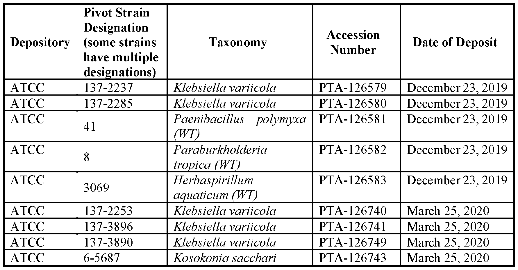 Plant Species Any of the methods described herein can be used to determine the nitrogen status of any plants that have economic, social and/or environmental value, such as food crops, fiber crops, oil crops, plants in the forestry or pulp and paper industries, feedstock for biofuel production, and/or ornamental plants. Non-limiting examples of crop plants include maize (e.g., sweet corn), rice, wheat, barley, sorghum, millet, oats, rye, triticale, buckwheat, sugar cane, onions, tomatoes, strawberries, and asparagus. For example, plants can be in the genus Hordeum, Oryza, Zea, and Triticeae. In some examples, any of the methods described herein can be used to determine the nitrogen status of any plants that may be used to produce economically valuable products such as a grain, a flour, a starch, a syrup, a meal, an oil, a film, a packaging, a nutraceutical product, a pulp, an animal feed, a fish fodder, a bulk material for industrial chemicals, a cereal product, a processed human food product, a sugar, an alcohol, and/or a protein. In some embodiments, any of the methods described herein can be used to determine the nitrogen status of cereal plants. Non-limiting examples of cereal plants include corn plants, canola plants, sorghum plants, wheat plants, and sunflower plants.
In some embodiments, any of the methods described herein can be used to determine the nitrogen status of any plants that are important or interesting for agriculture, horticulture, biomass for the production of biofuel molecules and other chemicals, and/or forestry. Some examples of these plants include pineapple, bamboo, banana, coconut, lily, grass peas, and grass; and dicotyledonous plants, such as, for example, peas, alfalfa, tomatillo, melon, chickpea, chicory, clover, kale, lentil, soybean, tobacco, potato, sweet potato, radish, cabbage, rape, apple trees, grape, cotton, sunflower, thale cress, canola, citrus (e.g., orange, mandarin, kumquat, lemon, lime, grapefruit, tangerine, tangelo, citron, and pomelo), pepper, bean, lettuce, Panicum virgatum (switch), Sorghum bicolor (sorghum, sudan), Miscanthus giganteus (miscanthus), Saccharum sp. (energycane), Populus balsamifera (poplar), Zea mays (corn), Glycine max (soybean), Brassica napus (canola), Triticum aestivum (wheat), Gossypium hirsutum (cotton), Oryza sativa (rice), Helianthus annuus (sunflower), Medicago sativa (alfalfa), Beta vulgaris (sugarbeet), Pennisetum glaucum (pearl millet), Panicum spp. Sorghum spp., Miscanthus spp., Saccharum spp., Erianthus spp., Populus spp., Secale cereale (rye), Salix spp. (willow), Eucalyptus spp. (eucalyptus), Triticosecale spp. (triticum- 25 wheat X rye), Carthamus tinctorius (safflower), Jatropha curcas (Jatropha), Ricinus communis (castor), Elaeis guineensis (oil palm), Phoenix dactylifera (date palm), Archontophoenix cunninghamiana (king palm), Syagrus romanzoffiana (queen palm), Linum usitatissimum (flax), Brassica juncea, Manihot esculenta (cassaya), Lycopersicon esculentum (tomato), Lactuca saliva (lettuce), Musa paradisiaca (banana), Solanum tuberosum (potato), Brassica oleracea (broccoli, cauliflower, brussel sprouts), Camellia sinensis (tea), Fragaria ananassa (strawberry), Theobroma cacao (cocoa), Coffea arabica (coffee), Vitis vinifera (grape), Ananas comosus (pineapple), Capsicum annum (hot & sweet pepper), Allium cepa (onion), Cucumis melo (melon), Cucumis sativus (cucumber), Cucurbita maxima (squash), Cucurbita moschata (squash), Spinacea oleracea (spinach), Citrullus lanatus (watermelon), Abelmoschus esculentus (okra), Solanum melongena (eggplant), Papaver somniferum (opium poppy), Papaver orientale, Taxus baccata, Taxus brevifolia, Artemisia annua, Cannabis saliva, Camptotheca acuminate, Catharanthus roseus, Vinca rosea, Cinchona officinalis, Coichicum autumnale, Veratrum californica, Digitalis lanata,
Digitalis purpurea, Dioscorea spp., Andrographis paniculata, Atropa belladonna, Datura stomonium, Berberis spp., Cephalotaxus spp., Ephedra sinica, Ephedra spp., Erythroxylum coca, Galanthus wornorii, Scopolia spp., Lycopodium serratum (Huperzia serrata), Lycopodium spp., Rauwolfia serpentina, Rauwolfia spp., Sanguinaria canadensis, Hyoscyamus spp., Calendula officinalis, Chrysanthemum parthenium, Coleus forskohlii, Tanacetum parthenium, Parthenium argentatum (guayule), Hevea spp. (rubber), Mentha spicata (mint), Mentha piperita (mint), Bixa orellana, Alstroemeria spp., Rosa spp. (rose), Dianthus caryophyllus (carnation), Petunia spp. (petunia), Poinsettia pulcherrima (poinsettia), Nicotiana tabacum (tobacco), Lupinus albus (lupin), Uniola paniculata (oats), Hordeum vulgare (barley), and Lolium spp. (rye). In some examples, a monocotyledonous plant may be used. Monocotyledonous plants belong to the orders of the Alismatales, Arales, Arecales, Bromeliales, Commelinales, Cyclanthales, Cyperales, Eriocaulales, Hydrocharitales, Juncales, Lilliales, Najadales, Orchidales, Pandanales, Poales, Restionales, Triuridales, Typhales, and Zingiberales. For example, the methods described herein can be performed on plant(s) belonging to the class of Gymnospermae include Cycadales, Ginkgoales, Gnetales, and Pinales. In some examples, the monocotyledonous plant can be selected from the group consisting of a maize, rice, wheat, barley, and sugarcane. In some examples, a dicotyledonous plant may be used, including those belonging to the orders of Aristochiales, Asterales, Batales, Campanulales, Capparales, Caryophyllales, Casuarinales, Celastrales, Cornales, Diapensales, Dilleniales, Dipsacales, Ebenales, Ericales, Eucomiales, Euphorbiales, Fabales, Fagales, Gentianales, Geraniales, Haloragales, Hamamelidales, Middles, Juglandales, Lamiales, Laurales, Lecythidales, Leitneriales, Magniolales, Malvales, Myricales, Myrtales, Nymphaeales, Papeverales, Piperales, Plantaginales, Plumb aginales, Podostemales, Polemoniales, Polygalales, Polygonales, Primulales, Proteales, Rafflesiales, Ranunculales, Rhamnales, Rosales, Rubiales, Salicales, Santales, Sapindales, Sarraceniaceae, Scrophulariales, Theales, Trochodendrales, Umbellales, Urticales, and Violates. Other non-limiting examples of suitable plants include mosses, lichens, and algae.
In some embodiments, the methods described herein are suitable for any of a variety of transgenic plants, non-transgenic plants, and hybrid plants thereof. Non-Genetically Modified Maize The methods described herein are suitable for determining the nitrogen status of any of a variety of non-genetically modified maize plants or part thereof. Furthermore, the methods and bacteria described herein are suitable for any of the following non-genetically modified hybrids, varieties, lineages, etc. In some embodiments, corn varieties generally fall under six categories: sweet corn, flint corn, popcorn, dent corn, pod corn, and flour corn. Sweet Corn Yellow su varieties include Earlivee, Early Sunglow, Sundance, Early Golden Bantam, Iochief, Merit, Jubilee, and Golden Cross Bantam. White su varieties include True Platinum, Country Gentleman, Silver Queen, and Stowell’s Evergreen. Bicolor su varieties include Sugar & Gold, Quickie, Double Standard, Butter & Sugar, Sugar Dots, Honey & Cream. Multicolor su varieties include Hookers, Triple Play, Painted Hill, Black Mexican/Aztec. Yellow se varieties include Buttergold, Precocious, Spring Treat, Sugar Buns, Colorow, Kandy King, Bodacious R/M, Tuxedo, Incredible, Merlin, Miracle, and Kandy Korn EH. White se varieties include Spring Snow, Sugar Pearl, Whiteout, Cloud Nine, Alpine, Silver King, and Argent. Bicolor se varieties include Sugar Baby, Fleet, Bon Jour, Trinity, Bi-Licious, Temptation, Luscious, Ambrosia, Accord, Brocade, Lancelot, Precious Gem, Peaches and Cream Mid EH, and Delectable R/M. Multicolor se varieties include Ruby Queen. Yellow sh2 varieties include Extra Early Super Sweet, Takeoff, Early Xtra Sweet, Raveline, Summer Sweet Yellow, Krispy King, Garrison, Illini Gold, Challenger, Passion, Excel, Jubilee SuperSweet, Illini Xtra Sweet, and Crisp ‘N Sweet. White sh2 varieties include Summer Sweet White, Tahoe, Aspen, Treasure, How Sweet It Is, and Camelot. Bicolor sh2 varieties include Summer Sweet Bicolor, Radiance, Honey ‘N Pearl, Aloha,
Dazzle, Hudson, and Phenomenal. Yellow sy varieties include Applause, Inferno, Honeytreat, and Honey Select. White sy varieties include Silver Duchess, Cinderella, Mattapoisett, Avalon, and Captivate. Bicolor sy varieties include Pay Dirt, Revelation, Renaissance, Charisma, Synergy, Montauk, Kristine, Serendipity/Providence, and Cameo. Yellow augmented supersweet varieties include Xtra-Tender 1ddA, Xtra-Tender 11dd, Mirai 131Y, Mirai 130Y, Vision, and Mirai 002. White augmented supersweet varieties include Xtra-Tender 3dda, Xtra-Tender 31dd, Mirai 421W, XTH 3673, and Devotion. Bicolor augmented supersweet varieties include Xtra-Tender 2dda, Xtra-Tender 21dd, Kickoff XR, Mirai 308BC, Anthem XR, Mirai 336BC, Fantastic XR, Triumph, Mirai 301BC, Stellar, American Dream, Mirai 350BC, and Obsession. Flint Corn Flint corn varieties include Bronze-Orange, Candy Red Flint, Floriani Red Flint, Glass Gem, Indian Ornamental (Rainbow), Mandan Red Flour, Painted Mountain, Petmecky, and Cherokee White Flour. Pop Corn Pop corn varieties include Monarch Butterfly, Yellow Butterfly, Midnight Blue, Ruby Red, Mixed Baby Rice, Queen Mauve, Mushroom Flake, Japanese Hull-less, Strawberry, Blue Shaman, Miniature Colored, Miniature Pink, Pennsylvania Dutch Butter Flavor, and Red Strawberry. Dent Corn Dent corn varieties include Bloody Butcher, Blue Clarage, Ohio Blue Clarage, Cherokee White Eagle, Hickory Cane, Hickory King, Jellicorse Twin, Kentucky Rainbow, Daymon Morgan’s Knt. Butcher, Leaming, Leaming’s Yellow, McCormack’s Blue Giant, Neal Paymaster, Pungo Creek Butcher, Reid’s Yellow Dent, Rotten Clarage, and Tennessee Red Cob.
In some embodiments, corn varieties include P1618W, P1306W, P1345, P1151, P1197, P0574, P0589, and P0157 (W = white corn). In some embodiments, the methods described herein are suitable for any hybrid of the maize varieties set forth herein. Genetically Modified Maize The methods and bacteria described herein are suitable for any of a hybrid, variety, lineage, etc. of genetically modified maize plants or part thereof. Non-Genetically Modified Sorghum The methods described herein are suitable for determining the nitrogen status of any of a variety of non-genetically modified sorghum plants or part thereof. Furthermore, the methods and bacteria described herein are suitable for any of the following non- genetically modified hybrids, varieties, lineages, etc. Sorghum is a genus of plant that includes multiple species of flowering plants in the Poaceae family and is also known as durra, jowari, and milo. In some embodiments, sorghum species include, Sorghum amplum, Sorghum angustum, Sorghum arundinaceum, Sorghum bicolor, Sorghum brachypodum, Sorghum bulbosum, Sorghum burmahicum, Sorghum controversum , Sorghum drummondii, Sorghum ecarinatum, Sorghum exstans, Sorghum grande, Sorghum halepense, Sorghum interjectum, Sorghum intrans, Sorghum laxiflorum, Sorghum leiocladum, Sorghum macrospermum, Sorghum matarankense, Sorghum nitidum, Sorghum plumosum, Sorghum propinquum, Sorghum purpureosericeum, Sorghum stipoideum, Sorghum timorense, Sorghum trichocladum, Sorghum versicolor, and Sorghum virgatum. Genetically Modified Sorghum The methods and bacteria described herein are suitable for any of a hybrid variety, lineage, etc, of genetically modified sorghum plants or a part thereof, including varieties with genetic modifications to increase grain production, increase plant growth rate, or increase plant yield.
Example processes FIG.3 is a flowchart 300 of an example set of operations performed to determine plant nitrogen status of a plant. In some embodiments, at least a portion of the operations depicted in the flowchart 300 can be performed by the various modules described above with references to FIG. 2G. For example, the biomass determination and/or the nitrogen status determination can be performed in a module substantially similar to the nitrogen assessment engine 220 described with reference to FIG.2G. The process represented in the flowchart 300 can include obtaining, from a chlorophyll sensor, a chlorophyll content of a plant (310). In some embodiments, the chlorophyll sensor can be substantially similar to the chlorophyll sensor 205 referenced in FIG. 2G. The process can also include obtaining, from one or more ranging sensors, a plurality of data points representing a structure of a plant (320). In some embodiments, the ranging sensors can be substantially similar to the ranging sensors 210 referenced in FIG. 2G. For example, the one or more ranging sensors can include at least one of: a LiDAR sensor, a radar sensor, or a sonar sensor. In some embodiments, the one or more ranging sensors can be disposed on a mobile device, or a vehicle, such as a land vehicle or a UAV. The process represented by the flowchart 300 can also include providing the data points to a trained machine-learning model to generate an estimate of one or more parameters related to a biomass of the plant (330). In some embodiments, the machine- learning model can be substantially similar to the machine-learning model 215 described with reference to FIG. 2G. In some embodiments, the machine-learning model can be trained via supervised learning, using a pre-labeled training data set. In some embodiments, a convolutional neural network (CNN) or a deep neural network (DNN) can be used as the machine-learning model. In some embodiments, the one or more parameters related to a biomass of the plant can include one or more of: stem diameter, plant volume, plant height, or leaf area index. In some embodiments, the process represented in FIG.3 can include determining, based on an output of the trained machine-learning model, the biomass of the plant (340). The output of the machine-learning model can be generated in response to the machine- learning model receiving the plurality of data points. In some embodiments, determining
the biomass of the plant based on the output of the trained-machine-learning model can include obtaining, from the trained machine-learning model as the one or more parameters related to the biomass of the plant, an estimate of volume of the plant and an estimate of a height of the plant. The biomass of the plant can then be determined based on such estimates as described in this document. In some embodiments, the process represented by the flowchart 300 can include determining, a plant nitrogen status of the plant based on the chlorophyll content and the biomass of the plant (350). This can be done, for example, by normalizing the biomass and the chlorophyll content, and determining the nitrogen status as a function of the normalized biomass and chlorophyll content, as described herein. The determined plant nitrogen status can be used for various purposes. In some embodiments, a signal may be generated based on the determined plant nitrogen status, the signal being configured to actuate an agricultural dispensing system to dispense one or more substances that affect the nitrogen status. For example, the actuating signal can trigger an agricultural dispensing system to adjust, start or stop dispensing one or more of: a fertilizer, a nitrogen stabilizer, a nitrification inhibitor, a urease inhibitor, or a microbe. In some embodiments, the determined nitrogen status of the plant can be stored in a database, wherein the nitrogen status of the plant is linked within the database to field characterization data associated with the plant. The field characterization data can include at least one of: precipitation data, temperature data, field boundaries data, soil type data, or fertility plan data. In some embodiments, the determined nitrogen status can be made available to a user (e.g., a farmer) over a user-interface displayed on a computing device or a mobile device. The determined nitrogen status may also be made available as feedback to other associated personnel, e.g., an agronomist, to determine whether a follow-up field visit needs to be scheduled. In some embodiments, the determined nitrogen status can be used to determine whether any changes in seeding rate or crop selection need to be implemented in subsequent years to improve yield.
Kits Also described herein are kits for performing any of the methods described herein. A kit can include any of the assays described herein (e.g., a lateral flow assay or series of lateral flow assays), and instruction for using the assay to determine the presence or absence of a target polypeptide (e.g., a polypeptide involved in nitrogen fixation) in a sample (e.g., in a sample of a rhizosphere of a plant (e.g., a non-leguminous plant)). In some embodiments, the kit includes two or more assays (e.g., lateral flow assays). In some embodiments, the two or more assays detect the same target polypeptide. In some case, the two or more assays detect different target polypeptides. In some embodiments, the kit also includes a container. For example, the container can be used to mix the sample and the lysis buffer. In some embodiments, the kit can also include a volume of lysis buffer. In some embodiments, the kit can also include a pipette or dropper. The invention will be further described in the following embodiments, which do not limit the scope of the invention described in the claims. Embodiment 1. A method of determining the presence or absence of a polypeptide involved in nitrogen fixation in a rhizosphere of a non-leguminous plant, comprising: (a) contacting a sample of soil from the rhizosphere with a lysis buffer, thereby producing a solution; (b) contacting the solution with a sample-receiving zone of a substrate, wherein the substrate further comprises a detection zone comprising a reactive agent that, directly or indirectly, produces a signal based on the presence or absence of the polypeptide involved in nitrogen fixation once the solution contacts the detection zone; (c) detecting the signal produced by the reactive agent about 5 seconds to about 1 hour after the solution contacts the detection zone; and (d) determining the presence or absence of the polypeptide involved in nitrogen fixation in the solution based on detection of the signal. Embodiment 2. The method of Embodiment 1, wherein the polypeptide involved in nitrogen fixation is selected from the group consisting of: nifH, nifD, and nifK.
Embodiment 3. The method of Embodiment 2, wherein the polypeptide involved in nitrogen fixation is nifH. Embodiment 4. The method of Embodiment 2, wherein the polypeptide involved in nitrogen fixation is nifD. Embodiment 5. The method of Embodiment 2, wherein the polypeptide involved in nitrogen fixation is nifK. Embodiment 6. The method of any one of Embodiments 1-5, wherein the reactive agent is an antibody or antigen-binding fragment of an antibody. Embodiment 7. The method of Embodiment 6, wherein the antibody is a monoclonal antibody. Embodiment 8. The method of Embodiment 6, wherein the antibody is a polyclonal antibody. Embodiment 9. The method of any one of Embodiments 1-8, wherein the method further comprises: comparing the detected signal to a signal produced using a reference sample. Embodiment 10. The method of any one of Embodiments1-9, wherein the signal is a visual signal. Embodiment 11. The method of any one of Embodiments 1-10, wherein the solution flows from the sample-receiving zone of the substrate to the detection zone of the substrate via capillary flow. Embodiment 12. The method of any one of Embodiments 1-11, wherein step (c) comprises detecting the signal produced by the reactive agent about 30 seconds to about 1 hour after the solution contacts the detection zone. Embodiment 13. The method of Embodiment 12, wherein step (c) comprises detecting the signal produced by the reactive agent about 1 minute to about 20 minutes after the solution contacts the detection zone. Embodiment 14. The method of any one of Embodiments 1-13, wherein the lysis buffer comprises one or more of phenol, sodium dodecyl sulfate, and sodium hydroxide. Embodiment 15. The method of any one of Embodiments 1-14, wherein the method further comprises: determining the amount of nitrogen in the rhizosphere.
Embodiment 16. The method of Embodiment 15, wherein determining the amount of nitrogen in the rhizosphere comprises determining the amount of one or more of NH4+, NH3, urea, NO3, and NO2 in the rhizosphere. Embodiment 17. The method of any one of Embodiments 1-16, wherein the method further comprises determining the nitrogen status of the non-leguminous plant. Embodiment 18. The method of Embodiment 17, wherein determining the nitrogen status of the non-leguminous plant comprises: (a) determining the chlorophyll content of the non-leguminous plant; (b) determining the biomass of the non-leguminous plant; (c) normalizing the determined biomass and the determined chlorophyll content for the plant; and (d) determining plant nitrogen status of the plant using the normalized chlorophyll content (CC) and the normalized biomass (PB) of the plant. Embodiment 19. The method of Embodiment 18, wherein the chlorophyll content is determined using a chlorophyll meter. Embodiment 20. The method of Embodiment 18 or 19, wherein the biomass is determined using a digital scale. Embodiment 21. The method of any one of Embodiments 18-20, wherein the nitrogen status of the non-leguminous plant is determined in step (d) using Formula I: Plant Nitrogen Status (NS) = ^(PB) + ^(CC). Embodiment 22. The method of Embodiment 21, wherein ^ is 0.80. Embodiment 23. The method of Embodiment 21 or 22, wherein ^ is 0.20. Embodiment 24. The method of any one of Embodiments 1-23, wherein the non- leguminous plant is selected from the group consisting of: maize, rice, wheat, barley, sorghum, millet, oats, rye triticale, buckwheat, sweet corn, sugar cane, onions, tomatoes, strawberries, and asparagus. Embodiment 25. The method of any one of Embodiments 1-24, wherein one or more of the non-leguminous plant, the rhizosphere of the non-leguminous plant, soil in which the non-leguminous plant was cultivated, or a seed from which the non- leguminous plant was grown was previously contacted with one or more genetically engineered bacteria.
Embodiment 26. The method of Embodiment 25, wherein the one or more genetically engineered bacteria is a genetically engineered bacterium comprising a genetic variation in a nitrogen fixation gene or a nitrogen-assimilation gene. Embodiment 27. The method of Embodiment 25 or 26, wherein the one or more bacteria is of a genus independently selected from Kosakonia, Rahnella, Klebsiella, Paenibacillus, Paraburkholderia, and Herbaspirillum. Embodiment 28. The method of Embodiment 27, wherein the one or more bacteria is of a species independently selected from: Kosakonia sacchari, Rahnella aquatilis, Klebsiella variicola, Paenibacillus polymyxa, Paraburkholderia tropica, and Herbaspirillum aquaticum. Embodiment 29. The method of any one of Embodiments 25-28, wherein the one or more bacteria comprise at least one strain selected from a group consisting of Klebsiella variicola and Kosakonia sacchari. Embodiment 30. The method of Embodiment 29, wherein the one or more bacteria comprise a Klebsiella variicola strain. Embodiment 31. The method of Embodiment 30, wherein the one or more bacteria comprise a Kosakonia sacchari strain. Embodiment 32. The method of any one of Embodiments 1-31, wherein the presence of the polypeptide involved in nitrogen fixation in the solution is determined in step (d). Embodiment 33. The method of any one of Embodiments 1-31, wherein the absence of the polypeptide involved in nitrogen fixation in the solution is determined in step (d). Embodiment 34. The method of Embodiment 33, wherein the method further comprises: applying a composition comprising one or more bacteria to one or more of the non-leguminous plant, to the rhizosphere of the non-leguminous plant, to the soil in which the non-leguminous plant is cultivated or to the surface of the seed of the non- leguminous plant.
Embodiment 35. The method of Embodiment 34, wherein the one or more bacteria is a genetically engineered bacterium comprising a genetic variation in a nitrogen fixation gene or a nitrogen-assimilation gene. Embodiment 36. The method of Embodiment 34 or 35, wherein the one or more bacteria is of a genus independently selected from Kosakonia, Rahnella, Klebsiella, Paenibacillus, Paraburkholderia, and Herbaspirillum. Embodiment 37. The method of Embodiment 36, wherein the one or more bacteria is of a species independently selected from: Kosakonia sacchari, Rahnella aquatilis, Klebsiella variicola, Paenibacillus polymyxa, Paraburkholderia tropica, and Herbaspirillum aquaticum. Embodiment 38. The method of any one of Embodiments 34-37, wherein the one or more bacteria comprise at least one strain selected from a group consisting of Klebsiella variicola and Kosakonia sacchari. Embodiment 39. The method of Embodiment 38, wherein the one or more bacteria comprise the strain Klebsiella variicola. Embodiment 40. The method of any one of Embodiments 34-37, wherein the one or more bacteria comprise at least one strain selected from Klebsiella variicola and Kosakonia sacchari. Embodiment 41. The method of cl Embodiment aim 40, wherein the one or more bacteria comprise a Kosakonia sacchari strain. Embodiment 42. The method of any one of Embodiments 33-41, wherein the method further comprises applying a nitrogen-containing fertilizer to one or more of the non-leguminous plant, the rhizosphere of the non-leguminous plant, and soil in which the non-leguminous plant is cultivated. Embodiment 43. A lateral flow assay system for determining the presence or absence of a polypeptide involved in nitrogen fixation in a sample, comprising: (a) a cartridge configured to hold a substrate; and (b) a substrate comprising a sample-receiving zone and a detection zone, wherein the detection zone comprises a reactive agent that produces a signal based on the
presence or absence of a nitrogen fixation polypeptide involved in nitrogen fixation in a solution contacted with the sample-receiving zone of the substrate. Embodiment 44. The lateral flow assay system of Embodiment 43, wherein the polypeptide involved in nitrogen fixation is selected from the group consisting of: nifH, nifD, and nifK. Embodiment 45. The lateral flow assay system of Embodiment 44, wherein the polypeptide involved in nitrogen fixation is nifH. Embodiment 46. The lateral flow assay system of Embodiment 44, wherein the polypeptide involved in nitrogen fixation is nifD. Embodiment 47. The lateral flow assay system of Embodiment 44, wherein the polypeptide involved in nitrogen fixation is nifK. Embodiment 48. The lateral flow assay system of any one of Embodiments 43-47, wherein the reactive agent is an antibody or antigen-binding fragment of an antibody. Embodiment 49. The lateral flow assay system of Embodiment 48, wherein the antibody is a monoclonal antibody. Embodiment 50. The lateral flow assay system of Embodiment 48, wherein the antibody is a polyclonal antibody. Embodiment 51. The lateral flow assay system of any one of Embodiments 43-50, wherein the substrate is configured to flow a solution from the sample-receiving zone of the substrate to the detection zone of the substrate via capillary flow. Embodiment 52. A kit comprising: (a) one or more lateral flow assay system of any one of Embodiments 43-51; and (b) instructions for using the lateral flow assay system to determine the presence or absence of a polypeptide involved in nitrogen fixation in a rhizosphere of a non-leguminous plant. Embodiment 53. The kit of Embodiment 52, wherein the kit comprises two or more lateral flow assay systems. Embodiment 54. The kit of Embodiment 52 or 53, wherein the kit further comprises a container. Embodiment 55. The kit of Embodiment 54, wherein the container comprises a volume of lysis buffer.
Embodiment 56. The kit of any one of Embodiments 52-55, wherein the kit further comprises a pipette or dropper. The invention will be further described in the following examples, which do not limit the scope of the invention described in the claims. EXAMPLES Example 1. Determining the presence or absence of a polypeptide involved in nitrogen fixation in a rhizosphere of a non-leguminous plant A sample from a rhizosphere of a non-leguminous plant is taken. The sample is contacted with a lysis buffer for an appropriate amount of time to lyse microbial cells contained in the sample. The resulting solution is contacted with a sample-receiving zone of a substrate made of a porous material capable to wicking a liquid sample. The solution migrates through the substrate toward a detection zone, optionally passing through a conjugation zone containing a soluble reactive agent comprising a signal molecule. When the soluble reactive agent comprising the signal molecule contacts the polypeptide involved in nitrogen fixation, it binds to a specific epitope of the polypeptide. When the complex of polypeptide and the soluble reactive agent reach the detection zone, the polypeptide binds to a reactive agent attached to the substrate, thereby forming a sandwich of the reactive agent attached to the substrate, the polypeptide, and the soluble reactive agent comprising the signal molecule in a test line of the detection zone. The presence of the signal molecule at the test line can be visualized. The detection zone can also have a control line. If the polypeptide involved in nitrogen fixation was present in the sample, a test line and a control line are observed. If the polypeptide involved in nitrogen fixation was not present in the sample, a test line is absent and a control line is observed. Example 2: Large-scale production of nitrogen-fixing bacteria This example describes the preparation of microbial culture to be tested in combination with extenders of the present disclosure.
Kosakonia sacchari strain PTA-126743 and Klebsiella variicola strain PTA- 126740 were separately grown in fermenters to saturation to create microbial culture broths. Portions of these microbial culture broths were subsequently concentrated 20X by tangential flow filtration. The cell concentrates were each blended 1 : 1 v/v with a formulation concentrate solution comprising 30% w/v sucrose and 15% w/v oligofructose to create liquid microbial stocks. These liquid microbial stocks/microbial concentrates were subsequently freeze dried in trays in a laboratory scale lyophilizer. After the completion of the lyophilization program, the dry material was milled to pass through a 500 micron mesh. Kosakonia sacchari strain PTA-126743 and Klebsiella variicola strain PTA-126740 freeze-dried powders were both aged 2 weeks at 21 °C prior to being reconstituted and mixed with the extender compositions for seed treatment. Freeze dried powders were reconstituted at 1 g per 10 mL of 1X PBS. Cell viability of the dried microbial powder was tested by plating samples and measuring colony forming units per gram of powder. Initial cell viability assays showed viability between 1 x 10¹¹and 1 x 10¹²CFU/gram of powder. Example 3: Coating of seeds with nitrogen-fixing microbes A solution containing (w/w) 1% K2HPO4, 0.5% KH2PO4, 15% polyvinylpyrrolidone vinyl acetate copolymer (PVP/VA), 20% sorbitol, and 63.5 % water was prepared and mixed with the dried microbes described in the above example and was then coated on to the surface of corn seeds using a laboratory scale Hege seed treater system. The coated seeds were allowed to dry at room temperature. The seeds were planted in typical soil in an agricultural field, using normal crop growth procedures for the location and soil type. Example 4: Soil sample collection Soil is collected to confirm the presence of live, active nitrogen-fixing bacteria in the rhizosphere (soil closely adhering to the root) of a field-grown corn plant treated with
nitrogen-fixing microbes. A 5 g sample of fresh root is collected from the plant. The root, along with the rhizosphere soil adhering to the root, is immediately mixed with 5 mL of buffer and detergent in a sterile 80 mL centrifuge tube. A control sample is collected from plants that have not been treated with nitrogen-fixing microbes. Example 5: SDS-PAGE and immunoblot to confirm presence of proteins involved in nitrogen fixation To confirm the presence of the nitrogen-fixing microbes in the soil, the samples are analyzed for the presence of the NifH protein involved in nitrogen fixation. The samples are mixed with a buffer solution containing a protease inhibitor, pH buffer, solvent for breaking the bacterial cell walls, and water. The samples are mixed for 60 seconds, and filtered to remove particulate material. The filtrate is collected. 0.1 µl of each filtrate sample is mixed with the appropriate buffer, and loaded on an SDS-PAGE electrophoresis system to separate the protein components. After the SDS-PAGE is complete, the proteins are transferred from the gel to a nitrocellulose sheet, and the separated proteins are analyzed by immunoblot, using a commercially available antibody to the nifH protein and a commercially available antibody-based detection system. Commercially available antibodies to other nitrogen- fixing proteins, such as nifK, and nifD, are also utilized to confirm the presence of these proteins in the soil. By use of this method, initial confirmation of the presence of the nitrogen-fixing proteins, and thus the nitrogen-fixing microbes in the soil, can be confirmed. Example 6: Testing the amount of the protein involved in nitrogen-fixation over time The above-described sampling method is used over the life of 50 corn plants, growing in a field. The plants are fertilized and treated normally, except that only 75% of the total synthetic nitrogen is used.50 control plants are also tested. The control plants are treated as above, but with 100% of the usual total synthetic nitrogen application. The plants are tested daily from 48 hours after planting, to corn harvest date. From this assay, viability of the microbes in the soil over the course of growth season is determined.
By use of this method, it is confirmed that the nitrogen-fixing microbe-treated plants are present in the soil and are excreting nitrogen over the course of the season. Example 7: Lateral flow assay method A sheet of lateral flow assay (LFA) test material made of nitrocellulose membrane is treated with a monoclonal antibody that binds to NifH (exemplary protein sequences below). The material is cut to form test strips (substrates), which are placed in an appropriate plastic test cartridge. NifH protein from Kosakonia sacchari (6-5687) (SEQ ID NO: 1): MTMRQCAIYGKGGIGKSTTTQNLVAALAEMGKKVMIVGCDPKADSTRLILHAK AQNTIMEMAAEVGSVEDLELEDVLQIGYGGVRCAESGGPEPGVGCAGRGVITAI NFLEEEGAYVPDLDFVFYDVLGDVVCGGFAMPIRENKAQEIYIVCSGEMMAMY AANNISKGIVKYAKSGKVRLGGLICNSRQTDREDELIIALAEKLGTQMIHFVPRD NIVQRAEIRRMTVIEYDPTCNQANEYRSLASKIVNNTKMVVPTPCTMDELEELLM EFGIMDVEDTSIIGKTAAEENAV NifH protein from Klebsiella variicola (137-2253) (SEQ ID NO: 2): MTMRQCAIYGKGGIGKSTTTQNLVAALAEMGKKVMIVGCDPKADSTRLILHAK AQNTIMEMAAEVGSVEDLELEDVLQIGYGDVRCAESGGPEPGVGCAGRGVITAI NFLEEEGAYEEDLDFVFYDVLGDVVCGGFAMPIRENKAQEIYIVCSGEMMAMY AANNISKGIVKYAKSGKVRLGGLICNSRKTDREDELIIALAEKLGTQMIHFVPRD NIVQRAEIRRMTVIEYDPTCQQANEYRQLAQKIVNNTKKVVPTPCTMDELESLL MEFGIMEEEDTSIIGKTAAEENAA The cartridge-test strip has a location for application of the filtrate from the soil sample (e.g., sample receiving zone), and a separate location for visualizing the results (e.g., detection zone). A 1 g sample of soil is taken at 2 inches from the stem, 2 inches below the soil surface. The soil is mixed with 3 mL of buffer solution (NaCl) and 3 mL of detergent
(together forming a lysis buffer), mixed for 30 seconds, and filtered with a Whatman filter paper. A 3-drop aliquot of the filtrate is placed on the sample receiving zone of the lateral flow assay test strip, and the test strip is allowed to develop for 15 minutes. The results are then visualized to confirm the presence of the nifH protein, and thus the presence of the functional nitrogen-fixing microorganisms. Example 8: Validation of the presence of nitrogen-fixing microorganisms in the field A field is planted with corn that has been treated with a mixture of two nitrogen- fixing microbes Kosakonia sacchari and Klebsiella variicola, both of which have been gene-edited to have derepressed, increased nitrogen fixation compared to non-gene-edited controls. At a time point of 30 days after planting, the soil is tested using a lateral flow assay test to confirm that the nitrogen fixing microbes are present, alive, and are fixing nitrogen at an adequate level. More specifically, the rhizosphere soil will be sampled when the growing corn crop is between the V2-V4 growth stages. Lack of identification of functioning microbes at these growth stages would allow growers to reapply the microbes or apply synthetic N fertilizer (the plants are small enough at V2-V4) to use equipment in the field to apply these things). By use of this method, the presence of live, active nitrogen-fixing bacteria can be confirmed. Example 9: Field management method A field is planted with corn that has been treated with a gene-edited nitrogen-fixing microbe Kosakonia sacchari. The seeds are coated with at least 1x 10⁴ microbes per seed. A control field is planted with identical corn seeds, except that the control corn seeds have not been treated with the microbe. The test field and control field are treated as per normal agricultural practice for the soil and region, except that the test field is treated with only 75% of the synthetic nitrogen that is present in the control field. At 1 week after planting, a lateral flow assay is performed on the microbe-treated field to confirm that the microbes are growing and excreting nitrogen, using the above-described lateral flow assay. If levels of nifH are below a certain specified level, the crop is either treated with additional in-
furrow liquid nitrogen-fixing microbe solution, or is treated with alternative nitrogen sources (synthetic or organic) as needed. The crop is tested each week, to confirm that the microbes are still viable and active. By use of this method, crops produce a high level of corn, with less synthetic nitrogen used. Further, a built-in method of managing and readjusting nitrogen levels as needed during the course of the season results in less variability in the crop yield. Example 10: Test kit for in-field testing A test kit for rapid field testing of the presence of the nitrogen-fixing bacteria is prepared. The kit contains a plastic cartridge fitted with a lateral flow assay test strip, a soil collection container having 2 mL of lysis buffer, a scoop for collecting about 1 g of soil, and instructions for use. The kit is assembled into a cardboard box and sealed to increase shelf life. Example 11. Measuring nitrogen status and uptake in corn plants in fields. Twelve corn plants were harvested from two areas of a field. One treatment area (Treated) in the field received biological nitrogen fixing microorganisms, including strains of Klebsiella variicola and Kosakonia sacchari, and had a 35 lbs reduction of synthetic nitrogen fertilizer compared to the grower’s standard practice. The second area of the field (Grower Standard Practice) used grower standard practice of synthetic nitrogen without the addition of biological nitrogen fixing microorganisms. Here, grower standard practices refers to the historical nutrient management plan used by the grower. Grower standard practice can differ between growers, fields, soil types, states, etc. depending on the nutrient needs of the soil and crop. This term is used to represent what the typical, historical nutrient management practice that a grower uses on their field. The biomass of each plant was measured using a digital scale then, the uppermost fully collared leaf from each of the twelve plants was removed. Chlorophyll content (CC) (μmol/m2) was measured in the middle of each leaf equal distance between the leaf edge and midrib using a chlorophyll meter (MC-100 Chlorophyll Concentration Meter, Apogee Instruments). This was repeated
four times per leaf. The four replicate values per plant were averaged together, resulting in a mean CC for each plant. Whole plant nitrogen content is a function of total plant biomass and plant organ nitrogen concentrations. Leaf chlorophyll concentration is proxy for leaf nitrogen concentration. In corn, leaves represent the major sink of nitrogen during vegetative growth leading into reproductive growth, when ears become the nitrogen sink. Therefore, plant biomass (PB) and CC were used to estimate relative plant nitrogen status: Nitrogen status = (PB)*(0.80) + (CC)* (0.20). The scaling factors for corn were determining using an iterative approach testing number scaling factors with a focus on accurate prediction compared to laboratory results. Estimated nitrogen uptake was subsequently calculated: (Nitrogen status) * (average nitrogen uptake by corn growth stage). To confirm repeatability, this test was performed at approximately 80 field sites in 13 states in the United States. Plant biomass (FIG.2A), CC (FIG.2B) and estimated plant nitrogen uptake (FIG.2C), as determined with this new test, were similar to results from laboratory analysis using standard nitrogen measurement assay (FIGs.2D-2F). There was more nitrogen in plants from treated areas relative to Grower Standard Practice areas in 71% (win/loss ratio) of the fields according to the laboratory nitrogen measurement assay. This new relative plant nitrogen assessment test accurately predicted 82% of these win/losses. Example 12. LiDAR-based computations Plant fresh weights and LiDAR data were collected from plants at the V8 stage of growth from seven research trials across the US (63 total replications). In these trials the recommended applied nitrogen was determined using previous crop history and a soil nitrogen analysis, and this full grower recommended nitrogen rate (100% NTC; where NTC is the nutrient transfer continuum) was applied as a positive control (100% NTC). A reduction of forty pounds per acre of nitrogen from the grower recommended rate (-40lb) was used as the negative control. The PROVEN®40 product was applied as a seed treatment
to the same hybrid seeds used across an entire site, and the product was tested at the -40lb nitrogen rate (-40lb PROVEN®40). For plant fresh weights, three plants per plot were collected according to the previously described method. This consisted of clipping the entire plant just above the soil surface and measuring total plant biomass in the field using a handheld scale. For LiDAR measurements, each plot was covered at approximately the same developmental as the V8 fresh weight measurements using a LiDAR device on a UAV. Point cloud data from the LiDAR device was used to create 3D models of each plot, and various traits known to correlate with plant biomass were generated using a variety of custom analysis scripts run in Python and R. Plant height –as computed by LiDAR—was able to discriminate the full nitrogen rate from the -40 lbs N rate with a p value of 0.0002 using a linear mixed-effects model analysis with either nitrogen rate or microbial application (treatment) as a fixed effect and location and replication as random effects. A Pearson correlation was also performed using average LiDAR height values for each plot compared to the average plant fresh weight from each plot. The outcome of this analysis showed that fresh weight and height by LiDAR are positively correlated with an R2 of 0.25. Example 13. Example computing systems A number of embodiments have been described. Nevertheless, it will be understood that various modifications may be made without departing from the spirit and scope of the disclosure. For example, various forms of the flows shown above can be used, with steps re-ordered, added, and/or removed. Embodiments of the subject matter and the functional operations described in this specification can be implemented in digital electronic circuitry, in tangibly-embodied computer software or firmware, in computer hardware, including the structures disclosed in this specification and their structural equivalents, or in combinations of one or more of them. Embodiments of the subject matter described in this specification can be implemented as one or more computer programs, i.e., one or more modules of computer program instructions encoded on a tangible non-transitory program carrier for execution
by, or to control the operation of, data processing apparatus. Alternatively, or in addition, the program instructions can be encoded on an artificially-generated propagated signal, e.g., a machine-generated electrical, optical, or electromagnetic signal, that is generated to encode information for transmission to suitable receiver apparatus for execution by a data processing apparatus. The computer storage medium can be a machine-readable storage device, a machine-readable storage substrate, a random or serial access memory device, or a combination of one or more of them. The term “data processing apparatus” refers to data processing hardware and encompasses all kinds of apparatus, devices, and machines for processing data, including by way of example a programmable processor, a computer, or multiple processors or computers. The apparatus can also be or further include special purpose logic circuitry, e.g., an FPGA (field programmable gate array) or an ASIC (application-specific integrated circuit). The apparatus can optionally include, in addition to hardware, code that creates an execution environment for computer programs, e.g., code that constitutes processor firmware, a protocol stack, a database management system, an operating system, or a combination of one or more of them. A computer program, which may also be referred to or described as a program, software, a software application, a module, a software module, a script, or code, can be written in any form of programming language, including compiled or interpreted languages, or declarative or procedural languages, and it can be deployed in any form, including as a stand-alone program or as a module, component, subroutine, or other unit suitable for use in a computing environment. A computer program may, but need not, correspond to a file in a file system. A program can be stored in a portion of a file that holds other programs or data, e.g., one or more scripts stored in a markup language document, in a single file dedicated to the program in question, or in multiple coordinated files, e.g., files that store one or more modules, sub-programs, or portions of code. A computer program can be deployed to be executed on one computer or on multiple computers that are located at one site or distributed across multiple sites and interconnected by a communication network.
The processes and logic flows described in this specification can be performed by one or more programmable computers executing one or more computer programs to perform functions by operating on input data and generating output. The processes and logic flows can also be performed by, and apparatus can also be implemented as, special purpose logic circuitry, e.g., an FPGA (field programmable gate array) or an ASIC (application-specific integrated circuit). Computers suitable for the execution of a computer program include, by way of example, general or special purpose microprocessors or both, or any other kind of central processing unit. Generally, a central processing unit will receive instructions and data from a read-only memory or a random access memory or both. The essential elements of a computer are a central processing unit for performing or executing instructions and one or more memory devices for storing instructions and data. Generally, a computer will also include, or be operatively coupled to receive data from or transfer data to, or both, one or more mass storage devices for storing data, e.g., magnetic, magneto-optical disks, or optical disks. However, a computer need not have such devices. Moreover, a computer can be embedded in another device, e.g., a mobile telephone, a smart phone, a personal digital assistant (PDA), a mobile audio or video player, a game console, a Global Positioning System (GPS) receiver, or a portable storage device, e.g., a universal serial bus (USB) flash drive, to name just a few. Computer-readable media suitable for storing computer program instructions and data include all forms of non-volatile memory, media and memory devices, including by way of example semiconductor memory devices, e.g., EPROM (erasable programmable read only memory), EEPROM (electrically erasable programmable read only memory), and flash memory devices; magnetic disks, e.g., internal hard disks or removable disks; magneto-optical disks; and CD-ROM (compact disc read only memory), and DVD-ROM (digital versatile disk read only memory) disks. The processor and the memory can be supplemented by, or incorporated in, special purpose logic circuitry. To provide for interaction with a user, embodiments of the subject matter described in this specification can be implemented on a computer having a display device, e.g., LCD (liquid crystal display), OLED (organic light emitting diode) or other monitor, for
displaying information to the user and a keyboard and a pointing device, e.g., a mouse or a trackball, by which the user can provide input to the computer. Other kinds of devices can be used to provide for interaction with a user as well; for example, feedback provided to the user can be any form of sensory feedback, e.g., visual feedback, auditory feedback, or tactile feedback; and input from the user can be received in any form, including acoustic, speech, or tactile input. In addition, a computer can interact with a user by sending documents to and receiving documents from a device that is used by the user; for example, by sending web pages to a web browser on a user’s device in response to requests received from the web browser. Embodiments of the subject matter described in this specification can be implemented in a computing system that includes a back-end component, e.g., as a data server, or that includes a middleware component, e.g., an application server, or that includes a front-end component, e.g., a client computer having a graphical user interface or a Web browser through which a user can interact with an implementation of the subject matter described in this specification, or any combination of one or more such back-end, middleware, or front-end components. The components of the system can be interconnected by any form or medium of digital data communication, e.g., a communication network. Examples of communication networks include a local area network (LAN) and a wide area network (WAN), e.g., the Internet. The computing system can include clients and servers. A client and server are generally remote from each other and typically interact through a communication network. The relationship of client and server arises by virtue of computer programs running on the respective computers and having a client-server relationship to each other. In some embodiments, a server transmits data, e.g., a Hypertext Markup Language (HTML) page, to a user device, e.g., for purposes of displaying data to and receiving user input from a user interacting with the user device, which acts as a client. Data generated at the user device, e.g., a result of the user interaction, can be received from the user device at the server. FIG. 4 shows an example of a computing device 400 and a mobile computing device 450 (also referred to herein as a wireless device) that are employed to execute
embodiments of the present disclosure. For example, the machine learning model 215 and/or the nitrogen assessment engine 220 described above may be implemented, at least in part, on a computing device 400, a mobile computing device 450, or a combination thereof. A computing device 400 or a mobile computing device 450 can include, or can be configured to communicate with, one or more chlorophyll sensors 205 and/or one or more ranging sensors 210. The computing device 400 is intended to represent various forms of digital computers, such as laptops, desktops, workstations, personal digital assistants, servers, blade servers, mainframes, and other appropriate computers. The mobile computing device 450 is intended to represent various forms of mobile devices, such as personal digital assistants, cellular telephones, smart-phones, AR (augmented reality) devices, and other similar computing devices. The components shown here, their connections and relationships, and their functions, are meant to be examples only, and are not meant to be limiting. The computing device 400 includes a processor 402, a memory 404, a storage device 406, a high-speed interface 408, and a low-speed interface 412. In some embodiments, the high-speed interface 408 connects to the memory 404 and multiple high- speed expansion ports 410. In some embodiments, the low-speed interface 412 connects to a low-speed expansion port 414 and the storage device 404. Each of the processor 402, the memory 404, the storage device 406, the high-speed interface 408, the high-speed expansion ports 410, and the low-speed interface 412, are interconnected using various buses, and may be mounted on a common motherboard or in other manners as appropriate. The processor 402 can process instructions for execution within the computing device 400, including instructions stored in the memory 404 and/or on the storage device 406 to display graphical information for a graphical user interface (GUI) on an external input/output device, such as a display 416 coupled to the high-speed interface 408. In other embodiments, multiple processors and/or multiple buses may be used, as appropriate, along with multiple memories and types of memory. In addition, multiple computing devices may be connected, with each device providing portions of the necessary operations (e.g., as a server bank, a group of blade servers, or a multi-processor system).
The memory 404 stores information within the computing device 400. In some embodiments, the memory 404 is a volatile memory unit or units. In some embodiments, the memory 404 is a non-volatile memory unit or units. The memory 404 may also be another form of a computer-readable medium, such as a magnetic or optical disk. The storage device 406 is capable of providing mass storage for the computing device 400. In some embodiments, the storage device 406 may be or include a computer- readable medium, such as a floppy disk device, a hard disk device, an optical disk device, a tape device, a flash memory, or other similar solid-state memory device, or an array of devices, including devices in a storage area network or other configurations. Instructions can be stored in an information carrier. The instructions, when executed by one or more processing devices, such as processor 402, perform one or more methods, such as those described above. The instructions can also be stored by one or more storage devices, such as computer-readable or machine-readable mediums, such as the memory 404, the storage device 406, or memory on the processor 402. The high-speed interface 408 manages bandwidth-intensive operations for the computing device 400, while the low-speed interface 412 manages lower bandwidth- intensive operations. Such allocation of functions is an example only. In some embodiments, the high-speed interface 408 is coupled to the memory 404, the display 416 (e.g., through a graphics processor or accelerator), and to the high-speed expansion ports 410, which may accept various expansion cards. In the implementation, the low-speed interface 412 is coupled to the storage device 406 and the low-speed expansion port 414. The low-speed expansion port 414, which may include various communication ports (e.g., Universal Serial Bus (USB), Bluetooth, Ethernet, wireless Ethernet) may be coupled to one or more input/output devices. Such input/output devices may include a scanner, a printing device, or a keyboard or mouse. The input/output devices may also be coupled to the low- speed expansion port 414 through a network adapter. Such network input/output devices may include, for example, a switch or router. The computing device 400 may be implemented in a number of different forms, as shown in the FIG. 4. For example, it can be implemented as a standard server 420, or multiple times in a group of such servers. In addition, it can be implemented in a personal
computer such as a laptop computer 422. It can also be implemented as part of a rack server system 424. Alternatively, components from the computing device 400 can be combined with other components in a mobile device, such as a mobile computing device 450. Each of such devices can contain one or more of the computing device 400 and the mobile computing device 450, and an entire system can be made up of multiple computing devices communicating with each other. The mobile computing device 450 includes a processor 452; a memory 464; an input/output device, such as a display 454; a communication interface 466; and a transceiver 468; among other components. In some embodiments, the mobile computing device 450 can include one or more ranging sensors such as LiDAR. The mobile computing device 450 can also be provided with a storage device, such as a micro-drive or other device, to provide additional storage. Each of the processor 452, the memory 464, the display 454, the communication interface 466, and the transceiver 468, are interconnected using various buses, and several of the components can be mounted on a common motherboard or in other manners as appropriate. In some embodiments, the mobile computing device 450 can include a camera device(s) (not shown). The processor 452 can execute instructions within the mobile computing device 450, including instructions stored in the memory 464. The processor 452 can be implemented as a chipset of chips that include separate and multiple analog and digital processors. For example, the processor 452 may be a Complex Instruction Set Computers (CISC) processor, a Reduced Instruction Set Computer (RISC) processor, or a Minimal Instruction Set Computer (MISC) processor. The processor 452 can provide, for example, for coordination of the other components of the mobile computing device 450, such as control of user interfaces (UIs), applications run by the mobile computing device 450, and/or wireless communication by the mobile computing device 450. In some embodiments, the processor 452 can communicate with a user through a control interface 458 and a display interface 456 coupled to the display 454. The display 454 can be, for example, a Thin-Film-Transistor Liquid Crystal Display (TFT) display, an Organic Light Emitting Diode (OLED) display, or other appropriate display technology. The display interface 456 can include appropriate circuitry for driving the display 454 to
present graphical and other information to a user. The control interface 458 can receive commands from a user and convert them for submission to the processor 452. In addition, an external interface 462 can provide communication with the processor 452, so as to enable near area communication of the mobile computing device 450 with other devices. The external interface 462 can provide, for example, for wired communication in some embodiments, or for wireless communication in other embodiments, and multiple interfaces may also be used. The memory 464 stores information within the mobile computing device 450. The memory 464 can be implemented as one or more of a computer-readable medium or media, a volatile memory unit or units, or a non-volatile memory unit or units. An expansion memory 474 can also be provided and connected to the mobile computing device 450 through an expansion interface 472, which can include, for example, a Single in Line Memory Module (SIMM) card interface. The expansion memory 474 can provide extra storage space for the mobile computing device 450, or can also store applications or other information for the mobile computing device 450. Specifically, the expansion memory 474 can include instructions to carry out or supplement the processes described above, and can include secure information also. Thus, for example, the expansion memory 474 can be provided as a security module for the mobile computing device 450, and can be programmed with instructions that permit secure use of the mobile computing device 450. In addition, secure applications can be provided via the SIMM cards, along with additional information, such as placing identifying information on the SIMM card in a non-hackable manner. The memory can include, for example, flash memory and/or non-volatile random access memory (NVRAM), as discussed below. In some embodiments, instructions are stored in an information carrier. The instructions, when executed by one or more processing devices, such as processor 452, perform one or more methods, such as those described above. The instructions can also be stored by one or more storage devices, such as one or more computer-readable or machine-readable mediums, such as the memory 464, the expansion memory 474, or memory on the processor 452. In some embodiments, the
instructions can be received in a propagated signal, such as, over the transceiver 468 or the external interface 462. The mobile computing device 450 can communicate wirelessly through the communication interface 466, which can include digital signal processing circuitry where necessary. The communication interface 466 can provide for communications under various modes or protocols, such as Global System for Mobile communications (GSM) voice calls, Short Message Service (SMS), Enhanced Messaging Service (EMS), Multimedia Messaging Service (MMS) messaging, code division multiple access (CDMA), time division multiple access (TDMA), Personal Digital Cellular (PDC), Wideband Code Division Multiple Access (WCDMA), CDMA2000, General Packet Radio Service (GPRS). Such communication can occur, for example, through the transceiver 468 using a radio frequency. In addition, short-range communication, such as using a Bluetooth or Wi-Fi, can occur. In addition, a Global Positioning System (GPS) receiver module 470 can provide additional navigation- and location-related wireless data to the mobile computing device 450, which can be used as appropriate by applications running on the mobile computing device 450. The mobile computing device 450 can also communicate audibly using an audio codec 460, which can receive spoken information from a user and convert it to usable digital information. The audio codec 460 can likewise generate audible sound for a user, such as through a speaker, e.g., in a handset of the mobile computing device 450. Such sound can include sound from voice telephone calls, can include recorded sound (e.g., voice messages, music files, etc.) and can also include sound generated by applications operating on the mobile computing device 450. Computing device 400 and/or 450 can also include USB (universal serial bus) flash drives. The USB flash drives can store operating systems and other applications. The USB flash drives can include input/output components, such as a wireless transmitter or USB connector that can be inserted into a USB port of another computing device. While this specification contains many specific implementation details, these should not be construed as limitations on the scope of what may be claimed, but rather as descriptions of features that may be specific to particular embodiments. Certain features
that are described in this specification in the context of separate embodiments can also be implemented in combination in a single embodiment. Conversely, various features that are described in the context of a single embodiment can also be implemented in multiple embodiments separately or in any suitable subcombination. Moreover, although features may be described above as acting in certain combinations and even initially claimed as such, one or more features from a claimed combination can in some embodiments be excised from the combination, and the claimed combination may be directed to a subcombination or variation of a subcombination. Similarly, while operations are depicted in the drawings in a particular order, this should not be understood as requiring that such operations be performed in the particular order shown or in sequential order, or that all illustrated operations be performed, to achieve desirable results. In certain circumstances, multitasking and parallel processing may be advantageous. Moreover, the separation of various system modules and components in the embodiments described above should not be understood as requiring such separation in all embodiments, and it should be understood that the described program components and systems can generally be integrated together in a single software product or packaged into multiple software products. In each instance where an HTML (hypertext markup language) file is mentioned, other file types or formats may be substituted. For instance, an HTML file may be replaced by an XML (extensible markup language), JSON (JavaScript object notation), plain text, or other types of files. Moreover, where a table or hash table is mentioned, other data structures (such as spreadsheets, relational databases, or structured files) may be used. Example 14. Nitrogen uptake determined by laboratory combustion analysis vs. with in- field analysis in corn Chlorophyll concentration and plant biomass are the basis for determining plant nitrogen content in real-time. In some embodiments, mass of the primary ear (PEM) of the corn plant may be helpful for determining plant nitrogen status. During reproductive growth stages, nitrogen is remobilized from the stalk and leaves of the plant to the primary
ear, making this an important nitrogen sink. When this is the case, plant nitrogen status of the plant is determined using Formula II: Plant Nitrogen Status (NS) = α(PB) + ^(CC) + c(PEM). In some embodiments, diameter of the stalk (SD) of the corn plant may be helpful for determining plant nitrogen status. During early vegetative growth, rate of stalk growth can be limited by nitrogen available for plant uptake. When this is the case, plant nitrogen status of the plant is determined using Formula III: Plant Nitrogen Status (NS) = α(PB) + ^(CC) + c(SD). Individual corn plants were sampled during the linear plant nitrogen assimilation growth period. Chlorophyll concentration (CC) was measured on the upper most collared leaf of each plant and the total biomass of the plant (PB) was assessed immediately after sampling. Plant nitrogen uptake (kg N per ha) was calculated as described herein, providing a real-time estimation of plant nitrogen status (NS). Plant nitrogen uptake was also measured for each plant using combustion analysis (see, for example, Miniat et al., supra). Pearson correlation illustrated a significant linear relationship between plant nitrogen uptake measured by the two analyses (FIG.5). Example 15. Use of the Reese-Nevins assay in field trials to test plants in the field with microbe vs. synthetic and/or synthetic depletion The Reese-Nevins assay, as described herein, was implemented 2325 times (2325 fields sampled) across 34 states. Corn ranged in growth stages from the time the plant had three visible collared leaves (V3) to the kernel dough stage (R4). At 575 fields, 35-40 lbs. of synthetic N was reduced and Pivot Bio PROVEN®40 was applied. A check strip was left in each field as a comparison area where the full synthetic nitrogen rate was applied (grower standard nitrogen management practice). Plant nitrogen uptake was determined using the assay across these 575 sampling events (FIG.6). For example, the assay was completed at a field, when the corn was at the silking growth stage (R1). Six plants were removed from the field in each treatment area (an area in which 35 lbs of synthetic nitrogen was replaced with Pivot Bio PROVEN®40 and an
untreated area with grower standard nitrogen management). Plants were removed by cutting the corn stalk flush with the soil surface and harvesting the aboveground biomass. Each plant was weighed with a hanging scale (AWS-SR-5, American Weigh Scales) and five-gallon bucket. The average biomass of the plants treated with Pivot Bio PROVEN®40 and 35 lbs less synthetic N was 865 g per plant. The average biomass of the plants in the untreated area with grower standard nitrogen management was 835 g per plant. The chlorophyll concentration of the leaf below and opposite of the primary ear was measured using a chlorophyll meter (MC-100 Chlorophyll Concentration Meter, Apogee Instruments). Chlorophyll concentration was measured in the middle of each leaf at an equal distance between the leaf edge and midrib and was repeated four times for each leaf. The average chlorophyll concentration of the plants treated with Pivot Bio PROVEN®40 and 35 lbs less synthetic N was 55.2 µm/m2. The average biomass of the plants in the untreated area with grower standard nitrogen management was 48.2 µm/m2. Nitrogen status of the plants treated with Pivot Bio PROVEN®40 and 35 lbs less synthetic N was 703.0 (865 * 0.80 + 55.2 * 0.20 = 703.0). The nitrogen status of the plants in the untreated area with grower standard nitrogen management was 677.7 (835 * 0.80 + 48.2 * 0.20 = 677.7). The plants treated with Pivot Bio PROVEN®40 and 35 lbs less synthetic N had a 3.7% relative increase in nitrogen compared to the plants in the untreated area with grower standard nitrogen management ((703.0 / 677.7 -1 ) * 100 = 3.7%). Additional variables useful for determining corn plant nitrogen status include mass of the primary ear and diameter of the stalk. Mass of the primary ear can be a useful measurement when determining corn plant nitrogen status during reproductive growth stages from kernel blister (R2) to maturity (R6). Nitrogen begins to accumulate in the corn plant shanks, husks, and cob at late vegetative growth stages (V14-18). At the beginning of reproductive growth stages (R1-2), storage of nitrogen in the shanks, husks, and cobs peaks accounting for approximately 15% of total plant nitrogen. At the same time (R1-2), nitrogen begins to remobilize from the stalk, leaf sheaths, leaf blades, shanks, husks, and cob into the grain. By corn maturity (R6), approximately 70% of total plant nitrogen is in the grain (ear) (Abendroth et al., Corn Growth and Development. Iowa State Univ. Extension publication PMR1009, 2011, available at store.extension.
iastate.edu/product/6065; and Bender et al., Agron. J. 105: 161-170 (2013)). This remobilization and accumulation of nitrogen in the ear from R2-R6 may make the ear an important nitrogen sink to measure late in the corn growing season. The critical nitrogen uptake phase for corn occurs from the time the plant has five visible collared leaves (V5) to tasseling (VT), and sufficient uptake of nitrogen (N) during this period is critical for plant growth and development (Abendroth et al., supra; and Bender et al., supra). Corn stalk diameters can be reduced if plant available nitrogen is limiting to development from V5-VT (Boomsma, et al., Agron. J., 101: 1426-1452 (2009)), possibly due to mobilization of stem carbohydrate reserves to the ear (Tollenaar et al., “Physiological parameters associated with differences in kernel set among maize hybrids,” pp. 115-130, In M. Westgate and K. Boote (ed.) Physiology and modeling kernel set in maize. Proc. of a Symp. Sponsored by Div. C-2 and A-3 of the CSSA and the ASA, Baltimore, MD. 18–22 Oct. 1998. CSSA and ASA, Madison, WI 2000). Therefore, corn stalk diameter may be an important indicator of plant nitrogen status from V5-VT when paired with leaf chlorophyll concentration and whole plant biomass. In some embodiments, modifications can be made to these methods to assess other crops. For example, the number of plants collected for crops like corn and soybeans for the Reese-Nevins assay can be different than for small grains like wheat, barley, or oats. For these small grains, it can be difficult to pick six plants for a biomass measurement. At the Feekes 5 growth stage and earlier, one linear foot of row of wheat plants can be sampled for a biomass measurement, and a subset of those plants (six leaves) can be used to measure chlorophyll content. Chlorophyll content can be measured on the most recent fully developed leaf when sampling before the plant begins heading (before Feekes 10). After the plant begins heading (Feekes 10 and later), the flag leaf can be sampled. Example 16. Determining the effect of lysis buffer to qualitatively measure nifH with lateral flow assays Two treatment solutions were prepared to demonstrate the effect of a lysis buffer: (i) deionized (DI) water + Klebsiella variicola (137-2253) (“2253”) and (ii) B-PER™
buffer (Thermo Fisher Scientific, Waltham, MA) + 2253. The lysis buffer contained a nonionic detergent in a phosphate buffer. The 2253 microbe was grown from a single colony in 5 mL media SOB agar plates for 20 hr at 30 ^C. Then 500 µL of overnight culture was transferred to a 1.5 mL tube, vortexed down to pellet the cells, and the supernatant was removed. The cells were resuspended in 1 mL DI water or B-PER™ buffer at a ratio of 1:100. The tip of an LFA strip was submerged into each solution for approximately 20 seconds while the liquid traveled up the strip. Then, the strip was removed while the reaction occurred (about 10 min). Only the LFA strips that contacted the B-PER™ buffer showed a signal (positive result). Thus, the results demonstrated that a reaction occurred when cells were lysed with lysis buffer, thereby demonstrating the presence of nifH, a polypeptide involved in nitrogen fixation. Example 17. Determining background signal Six treatments were prepared to observe the background signal comprising two different soil samples, with or without Klebsiella variicola (137-2253) (“2253”), and B- PER™ buffer (Thermo Fisher Scientific, Waltham, MA). (i) Soil Sample 1 without 2253 (ii) Soil Sample 1 + 2253 (iii) Soil Sample 2 without 2253 (iv) Soil Sample 2 + 2253 (v) Buffer only (negative control) (vi) Buffer only + 2253 Two soil samples from unfertilized fields were added to the lysis buffer in an approximate ratio of 4:1 (4 parts buffer for 1 part soil on a mass basis). The 2253 microbe was grown from a single colony in 5 mL media SOB agar plates for 20 hr at 30 ^C. Then 500 µL of overnight culture was transferred to a 1.5 mL tube, vortexed down to pellet the cells, and the supernatant was removed. The cells were resuspended in 1mL B-PER™ buffer at a ratio of 1:100. The tip of an LFA strip was submerged into each solution for
approximately 20 seconds while the liquid traveled up the strip. Then, the strip was removed while the reaction occurred (about 10 min). The results observed from the LFA strips are summarized in Table 2. Table 2 Example Soil Sample 2253 Signal Observed on LFA Strip 1 (com arative) 1 Absent No
Plant Species Any of the methods described herein can be used to determine the nitrogen status of any plants that have economic, social and/or environmental value, such as food crops, fiber crops, oil crops, plants in the forestry or pulp and paper industries, feedstock for biofuel production, and/or ornamental plants. Non-limiting examples of crop plants include maize (e.g., sweet corn), rice, wheat, barley, sorghum, millet, oats, rye, triticale, buckwheat, sugar cane, onions, tomatoes, strawberries, and asparagus. For example, plants can be in the genus Hordeum, Oryza, Zea, and Triticeae. In some examples, any of the methods described herein can be used to determine the nitrogen status of any plants that may be used to produce economically valuable products such as a grain, a flour, a starch, a syrup, a meal, an oil, a film, a packaging, a nutraceutical product, a pulp, an animal feed, a fish fodder, a bulk material for industrial chemicals, a cereal product, a processed human food product, a sugar, an alcohol, and/or a protein. In some embodiments, any of the methods described herein can be used to determine the nitrogen status of cereal plants. Non-limiting examples of cereal plants include corn plants, canola plants, sorghum plants, wheat plants, and sunflower plants.
In some embodiments, any of the methods described herein can be used to determine the nitrogen status of any plants that are important or interesting for agriculture, horticulture, biomass for the production of biofuel molecules and other chemicals, and/or forestry. Some examples of these plants include pineapple, bamboo, banana, coconut, lily, grass peas, and grass; and dicotyledonous plants, such as, for example, peas, alfalfa, tomatillo, melon, chickpea, chicory, clover, kale, lentil, soybean, tobacco, potato, sweet potato, radish, cabbage, rape, apple trees, grape, cotton, sunflower, thale cress, canola, citrus (e.g., orange, mandarin, kumquat, lemon, lime, grapefruit, tangerine, tangelo, citron, and pomelo), pepper, bean, lettuce, Panicum virgatum (switch), Sorghum bicolor (sorghum, sudan), Miscanthus giganteus (miscanthus), Saccharum sp. (energycane), Populus balsamifera (poplar), Zea mays (corn), Glycine max (soybean), Brassica napus (canola), Triticum aestivum (wheat), Gossypium hirsutum (cotton), Oryza sativa (rice), Helianthus annuus (sunflower), Medicago sativa (alfalfa), Beta vulgaris (sugarbeet), Pennisetum glaucum (pearl millet), Panicum spp. Sorghum spp., Miscanthus spp., Saccharum spp., Erianthus spp., Populus spp., Secale cereale (rye), Salix spp. (willow), Eucalyptus spp. (eucalyptus), Triticosecale spp. (triticum- 25 wheat X rye), Carthamus tinctorius (safflower), Jatropha curcas (Jatropha), Ricinus communis (castor), Elaeis guineensis (oil palm), Phoenix dactylifera (date palm), Archontophoenix cunninghamiana (king palm), Syagrus romanzoffiana (queen palm), Linum usitatissimum (flax), Brassica juncea, Manihot esculenta (cassaya), Lycopersicon esculentum (tomato), Lactuca saliva (lettuce), Musa paradisiaca (banana), Solanum tuberosum (potato), Brassica oleracea (broccoli, cauliflower, brussel sprouts), Camellia sinensis (tea), Fragaria ananassa (strawberry), Theobroma cacao (cocoa), Coffea arabica (coffee), Vitis vinifera (grape), Ananas comosus (pineapple), Capsicum annum (hot & sweet pepper), Allium cepa (onion), Cucumis melo (melon), Cucumis sativus (cucumber), Cucurbita maxima (squash), Cucurbita moschata (squash), Spinacea oleracea (spinach), Citrullus lanatus (watermelon), Abelmoschus esculentus (okra), Solanum melongena (eggplant), Papaver somniferum (opium poppy), Papaver orientale, Taxus baccata, Taxus brevifolia, Artemisia annua, Cannabis saliva, Camptotheca acuminate, Catharanthus roseus, Vinca rosea, Cinchona officinalis, Coichicum autumnale, Veratrum californica, Digitalis lanata,
Digitalis purpurea, Dioscorea spp., Andrographis paniculata, Atropa belladonna, Datura stomonium, Berberis spp., Cephalotaxus spp., Ephedra sinica, Ephedra spp., Erythroxylum coca, Galanthus wornorii, Scopolia spp., Lycopodium serratum (Huperzia serrata), Lycopodium spp., Rauwolfia serpentina, Rauwolfia spp., Sanguinaria canadensis, Hyoscyamus spp., Calendula officinalis, Chrysanthemum parthenium, Coleus forskohlii, Tanacetum parthenium, Parthenium argentatum (guayule), Hevea spp. (rubber), Mentha spicata (mint), Mentha piperita (mint), Bixa orellana, Alstroemeria spp., Rosa spp. (rose), Dianthus caryophyllus (carnation), Petunia spp. (petunia), Poinsettia pulcherrima (poinsettia), Nicotiana tabacum (tobacco), Lupinus albus (lupin), Uniola paniculata (oats), Hordeum vulgare (barley), and Lolium spp. (rye). In some examples, a monocotyledonous plant may be used. Monocotyledonous plants belong to the orders of the Alismatales, Arales, Arecales, Bromeliales, Commelinales, Cyclanthales, Cyperales, Eriocaulales, Hydrocharitales, Juncales, Lilliales, Najadales, Orchidales, Pandanales, Poales, Restionales, Triuridales, Typhales, and Zingiberales. For example, the methods described herein can be performed on plant(s) belonging to the class of Gymnospermae include Cycadales, Ginkgoales, Gnetales, and Pinales. In some examples, the monocotyledonous plant can be selected from the group consisting of a maize, rice, wheat, barley, and sugarcane. In some examples, a dicotyledonous plant may be used, including those belonging to the orders of Aristochiales, Asterales, Batales, Campanulales, Capparales, Caryophyllales, Casuarinales, Celastrales, Cornales, Diapensales, Dilleniales, Dipsacales, Ebenales, Ericales, Eucomiales, Euphorbiales, Fabales, Fagales, Gentianales, Geraniales, Haloragales, Hamamelidales, Middles, Juglandales, Lamiales, Laurales, Lecythidales, Leitneriales, Magniolales, Malvales, Myricales, Myrtales, Nymphaeales, Papeverales, Piperales, Plantaginales, Plumb aginales, Podostemales, Polemoniales, Polygalales, Polygonales, Primulales, Proteales, Rafflesiales, Ranunculales, Rhamnales, Rosales, Rubiales, Salicales, Santales, Sapindales, Sarraceniaceae, Scrophulariales, Theales, Trochodendrales, Umbellales, Urticales, and Violates. Other non-limiting examples of suitable plants include mosses, lichens, and algae.
In some embodiments, the methods described herein are suitable for any of a variety of transgenic plants, non-transgenic plants, and hybrid plants thereof. Non-Genetically Modified Maize The methods described herein are suitable for determining the nitrogen status of any of a variety of non-genetically modified maize plants or part thereof. Furthermore, the methods and bacteria described herein are suitable for any of the following non-genetically modified hybrids, varieties, lineages, etc. In some embodiments, corn varieties generally fall under six categories: sweet corn, flint corn, popcorn, dent corn, pod corn, and flour corn. Sweet Corn Yellow su varieties include Earlivee, Early Sunglow, Sundance, Early Golden Bantam, Iochief, Merit, Jubilee, and Golden Cross Bantam. White su varieties include True Platinum, Country Gentleman, Silver Queen, and Stowell’s Evergreen. Bicolor su varieties include Sugar & Gold, Quickie, Double Standard, Butter & Sugar, Sugar Dots, Honey & Cream. Multicolor su varieties include Hookers, Triple Play, Painted Hill, Black Mexican/Aztec. Yellow se varieties include Buttergold, Precocious, Spring Treat, Sugar Buns, Colorow, Kandy King, Bodacious R/M, Tuxedo, Incredible, Merlin, Miracle, and Kandy Korn EH. White se varieties include Spring Snow, Sugar Pearl, Whiteout, Cloud Nine, Alpine, Silver King, and Argent. Bicolor se varieties include Sugar Baby, Fleet, Bon Jour, Trinity, Bi-Licious, Temptation, Luscious, Ambrosia, Accord, Brocade, Lancelot, Precious Gem, Peaches and Cream Mid EH, and Delectable R/M. Multicolor se varieties include Ruby Queen. Yellow sh2 varieties include Extra Early Super Sweet, Takeoff, Early Xtra Sweet, Raveline, Summer Sweet Yellow, Krispy King, Garrison, Illini Gold, Challenger, Passion, Excel, Jubilee SuperSweet, Illini Xtra Sweet, and Crisp ‘N Sweet. White sh2 varieties include Summer Sweet White, Tahoe, Aspen, Treasure, How Sweet It Is, and Camelot. Bicolor sh2 varieties include Summer Sweet Bicolor, Radiance, Honey ‘N Pearl, Aloha,
Dazzle, Hudson, and Phenomenal. Yellow sy varieties include Applause, Inferno, Honeytreat, and Honey Select. White sy varieties include Silver Duchess, Cinderella, Mattapoisett, Avalon, and Captivate. Bicolor sy varieties include Pay Dirt, Revelation, Renaissance, Charisma, Synergy, Montauk, Kristine, Serendipity/Providence, and Cameo. Yellow augmented supersweet varieties include Xtra-Tender 1ddA, Xtra-Tender 11dd, Mirai 131Y, Mirai 130Y, Vision, and Mirai 002. White augmented supersweet varieties include Xtra-Tender 3dda, Xtra-Tender 31dd, Mirai 421W, XTH 3673, and Devotion. Bicolor augmented supersweet varieties include Xtra-Tender 2dda, Xtra-Tender 21dd, Kickoff XR, Mirai 308BC, Anthem XR, Mirai 336BC, Fantastic XR, Triumph, Mirai 301BC, Stellar, American Dream, Mirai 350BC, and Obsession. Flint Corn Flint corn varieties include Bronze-Orange, Candy Red Flint, Floriani Red Flint, Glass Gem, Indian Ornamental (Rainbow), Mandan Red Flour, Painted Mountain, Petmecky, and Cherokee White Flour. Pop Corn Pop corn varieties include Monarch Butterfly, Yellow Butterfly, Midnight Blue, Ruby Red, Mixed Baby Rice, Queen Mauve, Mushroom Flake, Japanese Hull-less, Strawberry, Blue Shaman, Miniature Colored, Miniature Pink, Pennsylvania Dutch Butter Flavor, and Red Strawberry. Dent Corn Dent corn varieties include Bloody Butcher, Blue Clarage, Ohio Blue Clarage, Cherokee White Eagle, Hickory Cane, Hickory King, Jellicorse Twin, Kentucky Rainbow, Daymon Morgan’s Knt. Butcher, Leaming, Leaming’s Yellow, McCormack’s Blue Giant, Neal Paymaster, Pungo Creek Butcher, Reid’s Yellow Dent, Rotten Clarage, and Tennessee Red Cob.
In some embodiments, corn varieties include P1618W, P1306W, P1345, P1151, P1197, P0574, P0589, and P0157 (W = white corn). In some embodiments, the methods described herein are suitable for any hybrid of the maize varieties set forth herein. Genetically Modified Maize The methods and bacteria described herein are suitable for any of a hybrid, variety, lineage, etc. of genetically modified maize plants or part thereof. Non-Genetically Modified Sorghum The methods described herein are suitable for determining the nitrogen status of any of a variety of non-genetically modified sorghum plants or part thereof. Furthermore, the methods and bacteria described herein are suitable for any of the following non- genetically modified hybrids, varieties, lineages, etc. Sorghum is a genus of plant that includes multiple species of flowering plants in the Poaceae family and is also known as durra, jowari, and milo. In some embodiments, sorghum species include, Sorghum amplum, Sorghum angustum, Sorghum arundinaceum, Sorghum bicolor, Sorghum brachypodum, Sorghum bulbosum, Sorghum burmahicum, Sorghum controversum , Sorghum drummondii, Sorghum ecarinatum, Sorghum exstans, Sorghum grande, Sorghum halepense, Sorghum interjectum, Sorghum intrans, Sorghum laxiflorum, Sorghum leiocladum, Sorghum macrospermum, Sorghum matarankense, Sorghum nitidum, Sorghum plumosum, Sorghum propinquum, Sorghum purpureosericeum, Sorghum stipoideum, Sorghum timorense, Sorghum trichocladum, Sorghum versicolor, and Sorghum virgatum. Genetically Modified Sorghum The methods and bacteria described herein are suitable for any of a hybrid variety, lineage, etc, of genetically modified sorghum plants or a part thereof, including varieties with genetic modifications to increase grain production, increase plant growth rate, or increase plant yield.
Example processes FIG.3 is a flowchart 300 of an example set of operations performed to determine plant nitrogen status of a plant. In some embodiments, at least a portion of the operations depicted in the flowchart 300 can be performed by the various modules described above with references to FIG. 2G. For example, the biomass determination and/or the nitrogen status determination can be performed in a module substantially similar to the nitrogen assessment engine 220 described with reference to FIG.2G. The process represented in the flowchart 300 can include obtaining, from a chlorophyll sensor, a chlorophyll content of a plant (310). In some embodiments, the chlorophyll sensor can be substantially similar to the chlorophyll sensor 205 referenced in FIG. 2G. The process can also include obtaining, from one or more ranging sensors, a plurality of data points representing a structure of a plant (320). In some embodiments, the ranging sensors can be substantially similar to the ranging sensors 210 referenced in FIG. 2G. For example, the one or more ranging sensors can include at least one of: a LiDAR sensor, a radar sensor, or a sonar sensor. In some embodiments, the one or more ranging sensors can be disposed on a mobile device, or a vehicle, such as a land vehicle or a UAV. The process represented by the flowchart 300 can also include providing the data points to a trained machine-learning model to generate an estimate of one or more parameters related to a biomass of the plant (330). In some embodiments, the machine- learning model can be substantially similar to the machine-learning model 215 described with reference to FIG. 2G. In some embodiments, the machine-learning model can be trained via supervised learning, using a pre-labeled training data set. In some embodiments, a convolutional neural network (CNN) or a deep neural network (DNN) can be used as the machine-learning model. In some embodiments, the one or more parameters related to a biomass of the plant can include one or more of: stem diameter, plant volume, plant height, or leaf area index. In some embodiments, the process represented in FIG.3 can include determining, based on an output of the trained machine-learning model, the biomass of the plant (340). The output of the machine-learning model can be generated in response to the machine- learning model receiving the plurality of data points. In some embodiments, determining
the biomass of the plant based on the output of the trained-machine-learning model can include obtaining, from the trained machine-learning model as the one or more parameters related to the biomass of the plant, an estimate of volume of the plant and an estimate of a height of the plant. The biomass of the plant can then be determined based on such estimates as described in this document. In some embodiments, the process represented by the flowchart 300 can include determining, a plant nitrogen status of the plant based on the chlorophyll content and the biomass of the plant (350). This can be done, for example, by normalizing the biomass and the chlorophyll content, and determining the nitrogen status as a function of the normalized biomass and chlorophyll content, as described herein. The determined plant nitrogen status can be used for various purposes. In some embodiments, a signal may be generated based on the determined plant nitrogen status, the signal being configured to actuate an agricultural dispensing system to dispense one or more substances that affect the nitrogen status. For example, the actuating signal can trigger an agricultural dispensing system to adjust, start or stop dispensing one or more of: a fertilizer, a nitrogen stabilizer, a nitrification inhibitor, a urease inhibitor, or a microbe. In some embodiments, the determined nitrogen status of the plant can be stored in a database, wherein the nitrogen status of the plant is linked within the database to field characterization data associated with the plant. The field characterization data can include at least one of: precipitation data, temperature data, field boundaries data, soil type data, or fertility plan data. In some embodiments, the determined nitrogen status can be made available to a user (e.g., a farmer) over a user-interface displayed on a computing device or a mobile device. The determined nitrogen status may also be made available as feedback to other associated personnel, e.g., an agronomist, to determine whether a follow-up field visit needs to be scheduled. In some embodiments, the determined nitrogen status can be used to determine whether any changes in seeding rate or crop selection need to be implemented in subsequent years to improve yield.
Kits Also described herein are kits for performing any of the methods described herein. A kit can include any of the assays described herein (e.g., a lateral flow assay or series of lateral flow assays), and instruction for using the assay to determine the presence or absence of a target polypeptide (e.g., a polypeptide involved in nitrogen fixation) in a sample (e.g., in a sample of a rhizosphere of a plant (e.g., a non-leguminous plant)). In some embodiments, the kit includes two or more assays (e.g., lateral flow assays). In some embodiments, the two or more assays detect the same target polypeptide. In some case, the two or more assays detect different target polypeptides. In some embodiments, the kit also includes a container. For example, the container can be used to mix the sample and the lysis buffer. In some embodiments, the kit can also include a volume of lysis buffer. In some embodiments, the kit can also include a pipette or dropper. The invention will be further described in the following embodiments, which do not limit the scope of the invention described in the claims. Embodiment 1. A method of determining the presence or absence of a polypeptide involved in nitrogen fixation in a rhizosphere of a non-leguminous plant, comprising: (a) contacting a sample of soil from the rhizosphere with a lysis buffer, thereby producing a solution; (b) contacting the solution with a sample-receiving zone of a substrate, wherein the substrate further comprises a detection zone comprising a reactive agent that, directly or indirectly, produces a signal based on the presence or absence of the polypeptide involved in nitrogen fixation once the solution contacts the detection zone; (c) detecting the signal produced by the reactive agent about 5 seconds to about 1 hour after the solution contacts the detection zone; and (d) determining the presence or absence of the polypeptide involved in nitrogen fixation in the solution based on detection of the signal. Embodiment 2. The method of Embodiment 1, wherein the polypeptide involved in nitrogen fixation is selected from the group consisting of: nifH, nifD, and nifK.
Embodiment 3. The method of Embodiment 2, wherein the polypeptide involved in nitrogen fixation is nifH. Embodiment 4. The method of Embodiment 2, wherein the polypeptide involved in nitrogen fixation is nifD. Embodiment 5. The method of Embodiment 2, wherein the polypeptide involved in nitrogen fixation is nifK. Embodiment 6. The method of any one of Embodiments 1-5, wherein the reactive agent is an antibody or antigen-binding fragment of an antibody. Embodiment 7. The method of Embodiment 6, wherein the antibody is a monoclonal antibody. Embodiment 8. The method of Embodiment 6, wherein the antibody is a polyclonal antibody. Embodiment 9. The method of any one of Embodiments 1-8, wherein the method further comprises: comparing the detected signal to a signal produced using a reference sample. Embodiment 10. The method of any one of Embodiments1-9, wherein the signal is a visual signal. Embodiment 11. The method of any one of Embodiments 1-10, wherein the solution flows from the sample-receiving zone of the substrate to the detection zone of the substrate via capillary flow. Embodiment 12. The method of any one of Embodiments 1-11, wherein step (c) comprises detecting the signal produced by the reactive agent about 30 seconds to about 1 hour after the solution contacts the detection zone. Embodiment 13. The method of Embodiment 12, wherein step (c) comprises detecting the signal produced by the reactive agent about 1 minute to about 20 minutes after the solution contacts the detection zone. Embodiment 14. The method of any one of Embodiments 1-13, wherein the lysis buffer comprises one or more of phenol, sodium dodecyl sulfate, and sodium hydroxide. Embodiment 15. The method of any one of Embodiments 1-14, wherein the method further comprises: determining the amount of nitrogen in the rhizosphere.
Embodiment 16. The method of Embodiment 15, wherein determining the amount of nitrogen in the rhizosphere comprises determining the amount of one or more of NH4+, NH3, urea, NO3, and NO2 in the rhizosphere. Embodiment 17. The method of any one of Embodiments 1-16, wherein the method further comprises determining the nitrogen status of the non-leguminous plant. Embodiment 18. The method of Embodiment 17, wherein determining the nitrogen status of the non-leguminous plant comprises: (a) determining the chlorophyll content of the non-leguminous plant; (b) determining the biomass of the non-leguminous plant; (c) normalizing the determined biomass and the determined chlorophyll content for the plant; and (d) determining plant nitrogen status of the plant using the normalized chlorophyll content (CC) and the normalized biomass (PB) of the plant. Embodiment 19. The method of Embodiment 18, wherein the chlorophyll content is determined using a chlorophyll meter. Embodiment 20. The method of Embodiment 18 or 19, wherein the biomass is determined using a digital scale. Embodiment 21. The method of any one of Embodiments 18-20, wherein the nitrogen status of the non-leguminous plant is determined in step (d) using Formula I: Plant Nitrogen Status (NS) = ^(PB) + ^(CC). Embodiment 22. The method of Embodiment 21, wherein ^ is 0.80. Embodiment 23. The method of Embodiment 21 or 22, wherein ^ is 0.20. Embodiment 24. The method of any one of Embodiments 1-23, wherein the non- leguminous plant is selected from the group consisting of: maize, rice, wheat, barley, sorghum, millet, oats, rye triticale, buckwheat, sweet corn, sugar cane, onions, tomatoes, strawberries, and asparagus. Embodiment 25. The method of any one of Embodiments 1-24, wherein one or more of the non-leguminous plant, the rhizosphere of the non-leguminous plant, soil in which the non-leguminous plant was cultivated, or a seed from which the non- leguminous plant was grown was previously contacted with one or more genetically engineered bacteria.
Embodiment 26. The method of Embodiment 25, wherein the one or more genetically engineered bacteria is a genetically engineered bacterium comprising a genetic variation in a nitrogen fixation gene or a nitrogen-assimilation gene. Embodiment 27. The method of Embodiment 25 or 26, wherein the one or more bacteria is of a genus independently selected from Kosakonia, Rahnella, Klebsiella, Paenibacillus, Paraburkholderia, and Herbaspirillum. Embodiment 28. The method of Embodiment 27, wherein the one or more bacteria is of a species independently selected from: Kosakonia sacchari, Rahnella aquatilis, Klebsiella variicola, Paenibacillus polymyxa, Paraburkholderia tropica, and Herbaspirillum aquaticum. Embodiment 29. The method of any one of Embodiments 25-28, wherein the one or more bacteria comprise at least one strain selected from a group consisting of Klebsiella variicola and Kosakonia sacchari. Embodiment 30. The method of Embodiment 29, wherein the one or more bacteria comprise a Klebsiella variicola strain. Embodiment 31. The method of Embodiment 30, wherein the one or more bacteria comprise a Kosakonia sacchari strain. Embodiment 32. The method of any one of Embodiments 1-31, wherein the presence of the polypeptide involved in nitrogen fixation in the solution is determined in step (d). Embodiment 33. The method of any one of Embodiments 1-31, wherein the absence of the polypeptide involved in nitrogen fixation in the solution is determined in step (d). Embodiment 34. The method of Embodiment 33, wherein the method further comprises: applying a composition comprising one or more bacteria to one or more of the non-leguminous plant, to the rhizosphere of the non-leguminous plant, to the soil in which the non-leguminous plant is cultivated or to the surface of the seed of the non- leguminous plant.
Embodiment 35. The method of Embodiment 34, wherein the one or more bacteria is a genetically engineered bacterium comprising a genetic variation in a nitrogen fixation gene or a nitrogen-assimilation gene. Embodiment 36. The method of Embodiment 34 or 35, wherein the one or more bacteria is of a genus independently selected from Kosakonia, Rahnella, Klebsiella, Paenibacillus, Paraburkholderia, and Herbaspirillum. Embodiment 37. The method of Embodiment 36, wherein the one or more bacteria is of a species independently selected from: Kosakonia sacchari, Rahnella aquatilis, Klebsiella variicola, Paenibacillus polymyxa, Paraburkholderia tropica, and Herbaspirillum aquaticum. Embodiment 38. The method of any one of Embodiments 34-37, wherein the one or more bacteria comprise at least one strain selected from a group consisting of Klebsiella variicola and Kosakonia sacchari. Embodiment 39. The method of Embodiment 38, wherein the one or more bacteria comprise the strain Klebsiella variicola. Embodiment 40. The method of any one of Embodiments 34-37, wherein the one or more bacteria comprise at least one strain selected from Klebsiella variicola and Kosakonia sacchari. Embodiment 41. The method of cl Embodiment aim 40, wherein the one or more bacteria comprise a Kosakonia sacchari strain. Embodiment 42. The method of any one of Embodiments 33-41, wherein the method further comprises applying a nitrogen-containing fertilizer to one or more of the non-leguminous plant, the rhizosphere of the non-leguminous plant, and soil in which the non-leguminous plant is cultivated. Embodiment 43. A lateral flow assay system for determining the presence or absence of a polypeptide involved in nitrogen fixation in a sample, comprising: (a) a cartridge configured to hold a substrate; and (b) a substrate comprising a sample-receiving zone and a detection zone, wherein the detection zone comprises a reactive agent that produces a signal based on the
presence or absence of a nitrogen fixation polypeptide involved in nitrogen fixation in a solution contacted with the sample-receiving zone of the substrate. Embodiment 44. The lateral flow assay system of Embodiment 43, wherein the polypeptide involved in nitrogen fixation is selected from the group consisting of: nifH, nifD, and nifK. Embodiment 45. The lateral flow assay system of Embodiment 44, wherein the polypeptide involved in nitrogen fixation is nifH. Embodiment 46. The lateral flow assay system of Embodiment 44, wherein the polypeptide involved in nitrogen fixation is nifD. Embodiment 47. The lateral flow assay system of Embodiment 44, wherein the polypeptide involved in nitrogen fixation is nifK. Embodiment 48. The lateral flow assay system of any one of Embodiments 43-47, wherein the reactive agent is an antibody or antigen-binding fragment of an antibody. Embodiment 49. The lateral flow assay system of Embodiment 48, wherein the antibody is a monoclonal antibody. Embodiment 50. The lateral flow assay system of Embodiment 48, wherein the antibody is a polyclonal antibody. Embodiment 51. The lateral flow assay system of any one of Embodiments 43-50, wherein the substrate is configured to flow a solution from the sample-receiving zone of the substrate to the detection zone of the substrate via capillary flow. Embodiment 52. A kit comprising: (a) one or more lateral flow assay system of any one of Embodiments 43-51; and (b) instructions for using the lateral flow assay system to determine the presence or absence of a polypeptide involved in nitrogen fixation in a rhizosphere of a non-leguminous plant. Embodiment 53. The kit of Embodiment 52, wherein the kit comprises two or more lateral flow assay systems. Embodiment 54. The kit of Embodiment 52 or 53, wherein the kit further comprises a container. Embodiment 55. The kit of Embodiment 54, wherein the container comprises a volume of lysis buffer.
Embodiment 56. The kit of any one of Embodiments 52-55, wherein the kit further comprises a pipette or dropper. The invention will be further described in the following examples, which do not limit the scope of the invention described in the claims. EXAMPLES Example 1. Determining the presence or absence of a polypeptide involved in nitrogen fixation in a rhizosphere of a non-leguminous plant A sample from a rhizosphere of a non-leguminous plant is taken. The sample is contacted with a lysis buffer for an appropriate amount of time to lyse microbial cells contained in the sample. The resulting solution is contacted with a sample-receiving zone of a substrate made of a porous material capable to wicking a liquid sample. The solution migrates through the substrate toward a detection zone, optionally passing through a conjugation zone containing a soluble reactive agent comprising a signal molecule. When the soluble reactive agent comprising the signal molecule contacts the polypeptide involved in nitrogen fixation, it binds to a specific epitope of the polypeptide. When the complex of polypeptide and the soluble reactive agent reach the detection zone, the polypeptide binds to a reactive agent attached to the substrate, thereby forming a sandwich of the reactive agent attached to the substrate, the polypeptide, and the soluble reactive agent comprising the signal molecule in a test line of the detection zone. The presence of the signal molecule at the test line can be visualized. The detection zone can also have a control line. If the polypeptide involved in nitrogen fixation was present in the sample, a test line and a control line are observed. If the polypeptide involved in nitrogen fixation was not present in the sample, a test line is absent and a control line is observed. Example 2: Large-scale production of nitrogen-fixing bacteria This example describes the preparation of microbial culture to be tested in combination with extenders of the present disclosure.
Kosakonia sacchari strain PTA-126743 and Klebsiella variicola strain PTA- 126740 were separately grown in fermenters to saturation to create microbial culture broths. Portions of these microbial culture broths were subsequently concentrated 20X by tangential flow filtration. The cell concentrates were each blended 1 : 1 v/v with a formulation concentrate solution comprising 30% w/v sucrose and 15% w/v oligofructose to create liquid microbial stocks. These liquid microbial stocks/microbial concentrates were subsequently freeze dried in trays in a laboratory scale lyophilizer. After the completion of the lyophilization program, the dry material was milled to pass through a 500 micron mesh. Kosakonia sacchari strain PTA-126743 and Klebsiella variicola strain PTA-126740 freeze-dried powders were both aged 2 weeks at 21 °C prior to being reconstituted and mixed with the extender compositions for seed treatment. Freeze dried powders were reconstituted at 1 g per 10 mL of 1X PBS. Cell viability of the dried microbial powder was tested by plating samples and measuring colony forming units per gram of powder. Initial cell viability assays showed viability between 1 x 10¹¹and 1 x 10¹²CFU/gram of powder. Example 3: Coating of seeds with nitrogen-fixing microbes A solution containing (w/w) 1% K2HPO4, 0.5% KH2PO4, 15% polyvinylpyrrolidone vinyl acetate copolymer (PVP/VA), 20% sorbitol, and 63.5 % water was prepared and mixed with the dried microbes described in the above example and was then coated on to the surface of corn seeds using a laboratory scale Hege seed treater system. The coated seeds were allowed to dry at room temperature. The seeds were planted in typical soil in an agricultural field, using normal crop growth procedures for the location and soil type. Example 4: Soil sample collection Soil is collected to confirm the presence of live, active nitrogen-fixing bacteria in the rhizosphere (soil closely adhering to the root) of a field-grown corn plant treated with
nitrogen-fixing microbes. A 5 g sample of fresh root is collected from the plant. The root, along with the rhizosphere soil adhering to the root, is immediately mixed with 5 mL of buffer and detergent in a sterile 80 mL centrifuge tube. A control sample is collected from plants that have not been treated with nitrogen-fixing microbes. Example 5: SDS-PAGE and immunoblot to confirm presence of proteins involved in nitrogen fixation To confirm the presence of the nitrogen-fixing microbes in the soil, the samples are analyzed for the presence of the NifH protein involved in nitrogen fixation. The samples are mixed with a buffer solution containing a protease inhibitor, pH buffer, solvent for breaking the bacterial cell walls, and water. The samples are mixed for 60 seconds, and filtered to remove particulate material. The filtrate is collected. 0.1 µl of each filtrate sample is mixed with the appropriate buffer, and loaded on an SDS-PAGE electrophoresis system to separate the protein components. After the SDS-PAGE is complete, the proteins are transferred from the gel to a nitrocellulose sheet, and the separated proteins are analyzed by immunoblot, using a commercially available antibody to the nifH protein and a commercially available antibody-based detection system. Commercially available antibodies to other nitrogen- fixing proteins, such as nifK, and nifD, are also utilized to confirm the presence of these proteins in the soil. By use of this method, initial confirmation of the presence of the nitrogen-fixing proteins, and thus the nitrogen-fixing microbes in the soil, can be confirmed. Example 6: Testing the amount of the protein involved in nitrogen-fixation over time The above-described sampling method is used over the life of 50 corn plants, growing in a field. The plants are fertilized and treated normally, except that only 75% of the total synthetic nitrogen is used.50 control plants are also tested. The control plants are treated as above, but with 100% of the usual total synthetic nitrogen application. The plants are tested daily from 48 hours after planting, to corn harvest date. From this assay, viability of the microbes in the soil over the course of growth season is determined.
By use of this method, it is confirmed that the nitrogen-fixing microbe-treated plants are present in the soil and are excreting nitrogen over the course of the season. Example 7: Lateral flow assay method A sheet of lateral flow assay (LFA) test material made of nitrocellulose membrane is treated with a monoclonal antibody that binds to NifH (exemplary protein sequences below). The material is cut to form test strips (substrates), which are placed in an appropriate plastic test cartridge. NifH protein from Kosakonia sacchari (6-5687) (SEQ ID NO: 1): MTMRQCAIYGKGGIGKSTTTQNLVAALAEMGKKVMIVGCDPKADSTRLILHAK AQNTIMEMAAEVGSVEDLELEDVLQIGYGGVRCAESGGPEPGVGCAGRGVITAI NFLEEEGAYVPDLDFVFYDVLGDVVCGGFAMPIRENKAQEIYIVCSGEMMAMY AANNISKGIVKYAKSGKVRLGGLICNSRQTDREDELIIALAEKLGTQMIHFVPRD NIVQRAEIRRMTVIEYDPTCNQANEYRSLASKIVNNTKMVVPTPCTMDELEELLM EFGIMDVEDTSIIGKTAAEENAV NifH protein from Klebsiella variicola (137-2253) (SEQ ID NO: 2): MTMRQCAIYGKGGIGKSTTTQNLVAALAEMGKKVMIVGCDPKADSTRLILHAK AQNTIMEMAAEVGSVEDLELEDVLQIGYGDVRCAESGGPEPGVGCAGRGVITAI NFLEEEGAYEEDLDFVFYDVLGDVVCGGFAMPIRENKAQEIYIVCSGEMMAMY AANNISKGIVKYAKSGKVRLGGLICNSRKTDREDELIIALAEKLGTQMIHFVPRD NIVQRAEIRRMTVIEYDPTCQQANEYRQLAQKIVNNTKKVVPTPCTMDELESLL MEFGIMEEEDTSIIGKTAAEENAA The cartridge-test strip has a location for application of the filtrate from the soil sample (e.g., sample receiving zone), and a separate location for visualizing the results (e.g., detection zone). A 1 g sample of soil is taken at 2 inches from the stem, 2 inches below the soil surface. The soil is mixed with 3 mL of buffer solution (NaCl) and 3 mL of detergent
(together forming a lysis buffer), mixed for 30 seconds, and filtered with a Whatman filter paper. A 3-drop aliquot of the filtrate is placed on the sample receiving zone of the lateral flow assay test strip, and the test strip is allowed to develop for 15 minutes. The results are then visualized to confirm the presence of the nifH protein, and thus the presence of the functional nitrogen-fixing microorganisms. Example 8: Validation of the presence of nitrogen-fixing microorganisms in the field A field is planted with corn that has been treated with a mixture of two nitrogen- fixing microbes Kosakonia sacchari and Klebsiella variicola, both of which have been gene-edited to have derepressed, increased nitrogen fixation compared to non-gene-edited controls. At a time point of 30 days after planting, the soil is tested using a lateral flow assay test to confirm that the nitrogen fixing microbes are present, alive, and are fixing nitrogen at an adequate level. More specifically, the rhizosphere soil will be sampled when the growing corn crop is between the V2-V4 growth stages. Lack of identification of functioning microbes at these growth stages would allow growers to reapply the microbes or apply synthetic N fertilizer (the plants are small enough at V2-V4) to use equipment in the field to apply these things). By use of this method, the presence of live, active nitrogen-fixing bacteria can be confirmed. Example 9: Field management method A field is planted with corn that has been treated with a gene-edited nitrogen-fixing microbe Kosakonia sacchari. The seeds are coated with at least 1x 10⁴ microbes per seed. A control field is planted with identical corn seeds, except that the control corn seeds have not been treated with the microbe. The test field and control field are treated as per normal agricultural practice for the soil and region, except that the test field is treated with only 75% of the synthetic nitrogen that is present in the control field. At 1 week after planting, a lateral flow assay is performed on the microbe-treated field to confirm that the microbes are growing and excreting nitrogen, using the above-described lateral flow assay. If levels of nifH are below a certain specified level, the crop is either treated with additional in-
furrow liquid nitrogen-fixing microbe solution, or is treated with alternative nitrogen sources (synthetic or organic) as needed. The crop is tested each week, to confirm that the microbes are still viable and active. By use of this method, crops produce a high level of corn, with less synthetic nitrogen used. Further, a built-in method of managing and readjusting nitrogen levels as needed during the course of the season results in less variability in the crop yield. Example 10: Test kit for in-field testing A test kit for rapid field testing of the presence of the nitrogen-fixing bacteria is prepared. The kit contains a plastic cartridge fitted with a lateral flow assay test strip, a soil collection container having 2 mL of lysis buffer, a scoop for collecting about 1 g of soil, and instructions for use. The kit is assembled into a cardboard box and sealed to increase shelf life. Example 11. Measuring nitrogen status and uptake in corn plants in fields. Twelve corn plants were harvested from two areas of a field. One treatment area (Treated) in the field received biological nitrogen fixing microorganisms, including strains of Klebsiella variicola and Kosakonia sacchari, and had a 35 lbs reduction of synthetic nitrogen fertilizer compared to the grower’s standard practice. The second area of the field (Grower Standard Practice) used grower standard practice of synthetic nitrogen without the addition of biological nitrogen fixing microorganisms. Here, grower standard practices refers to the historical nutrient management plan used by the grower. Grower standard practice can differ between growers, fields, soil types, states, etc. depending on the nutrient needs of the soil and crop. This term is used to represent what the typical, historical nutrient management practice that a grower uses on their field. The biomass of each plant was measured using a digital scale then, the uppermost fully collared leaf from each of the twelve plants was removed. Chlorophyll content (CC) (μmol/m2) was measured in the middle of each leaf equal distance between the leaf edge and midrib using a chlorophyll meter (MC-100 Chlorophyll Concentration Meter, Apogee Instruments). This was repeated
four times per leaf. The four replicate values per plant were averaged together, resulting in a mean CC for each plant. Whole plant nitrogen content is a function of total plant biomass and plant organ nitrogen concentrations. Leaf chlorophyll concentration is proxy for leaf nitrogen concentration. In corn, leaves represent the major sink of nitrogen during vegetative growth leading into reproductive growth, when ears become the nitrogen sink. Therefore, plant biomass (PB) and CC were used to estimate relative plant nitrogen status: Nitrogen status = (PB)*(0.80) + (CC)* (0.20). The scaling factors for corn were determining using an iterative approach testing number scaling factors with a focus on accurate prediction compared to laboratory results. Estimated nitrogen uptake was subsequently calculated: (Nitrogen status) * (average nitrogen uptake by corn growth stage). To confirm repeatability, this test was performed at approximately 80 field sites in 13 states in the United States. Plant biomass (FIG.2A), CC (FIG.2B) and estimated plant nitrogen uptake (FIG.2C), as determined with this new test, were similar to results from laboratory analysis using standard nitrogen measurement assay (FIGs.2D-2F). There was more nitrogen in plants from treated areas relative to Grower Standard Practice areas in 71% (win/loss ratio) of the fields according to the laboratory nitrogen measurement assay. This new relative plant nitrogen assessment test accurately predicted 82% of these win/losses. Example 12. LiDAR-based computations Plant fresh weights and LiDAR data were collected from plants at the V8 stage of growth from seven research trials across the US (63 total replications). In these trials the recommended applied nitrogen was determined using previous crop history and a soil nitrogen analysis, and this full grower recommended nitrogen rate (100% NTC; where NTC is the nutrient transfer continuum) was applied as a positive control (100% NTC). A reduction of forty pounds per acre of nitrogen from the grower recommended rate (-40lb) was used as the negative control. The PROVEN®40 product was applied as a seed treatment
to the same hybrid seeds used across an entire site, and the product was tested at the -40lb nitrogen rate (-40lb PROVEN®40). For plant fresh weights, three plants per plot were collected according to the previously described method. This consisted of clipping the entire plant just above the soil surface and measuring total plant biomass in the field using a handheld scale. For LiDAR measurements, each plot was covered at approximately the same developmental as the V8 fresh weight measurements using a LiDAR device on a UAV. Point cloud data from the LiDAR device was used to create 3D models of each plot, and various traits known to correlate with plant biomass were generated using a variety of custom analysis scripts run in Python and R. Plant height –as computed by LiDAR—was able to discriminate the full nitrogen rate from the -40 lbs N rate with a p value of 0.0002 using a linear mixed-effects model analysis with either nitrogen rate or microbial application (treatment) as a fixed effect and location and replication as random effects. A Pearson correlation was also performed using average LiDAR height values for each plot compared to the average plant fresh weight from each plot. The outcome of this analysis showed that fresh weight and height by LiDAR are positively correlated with an R2 of 0.25. Example 13. Example computing systems A number of embodiments have been described. Nevertheless, it will be understood that various modifications may be made without departing from the spirit and scope of the disclosure. For example, various forms of the flows shown above can be used, with steps re-ordered, added, and/or removed. Embodiments of the subject matter and the functional operations described in this specification can be implemented in digital electronic circuitry, in tangibly-embodied computer software or firmware, in computer hardware, including the structures disclosed in this specification and their structural equivalents, or in combinations of one or more of them. Embodiments of the subject matter described in this specification can be implemented as one or more computer programs, i.e., one or more modules of computer program instructions encoded on a tangible non-transitory program carrier for execution
by, or to control the operation of, data processing apparatus. Alternatively, or in addition, the program instructions can be encoded on an artificially-generated propagated signal, e.g., a machine-generated electrical, optical, or electromagnetic signal, that is generated to encode information for transmission to suitable receiver apparatus for execution by a data processing apparatus. The computer storage medium can be a machine-readable storage device, a machine-readable storage substrate, a random or serial access memory device, or a combination of one or more of them. The term “data processing apparatus” refers to data processing hardware and encompasses all kinds of apparatus, devices, and machines for processing data, including by way of example a programmable processor, a computer, or multiple processors or computers. The apparatus can also be or further include special purpose logic circuitry, e.g., an FPGA (field programmable gate array) or an ASIC (application-specific integrated circuit). The apparatus can optionally include, in addition to hardware, code that creates an execution environment for computer programs, e.g., code that constitutes processor firmware, a protocol stack, a database management system, an operating system, or a combination of one or more of them. A computer program, which may also be referred to or described as a program, software, a software application, a module, a software module, a script, or code, can be written in any form of programming language, including compiled or interpreted languages, or declarative or procedural languages, and it can be deployed in any form, including as a stand-alone program or as a module, component, subroutine, or other unit suitable for use in a computing environment. A computer program may, but need not, correspond to a file in a file system. A program can be stored in a portion of a file that holds other programs or data, e.g., one or more scripts stored in a markup language document, in a single file dedicated to the program in question, or in multiple coordinated files, e.g., files that store one or more modules, sub-programs, or portions of code. A computer program can be deployed to be executed on one computer or on multiple computers that are located at one site or distributed across multiple sites and interconnected by a communication network.
The processes and logic flows described in this specification can be performed by one or more programmable computers executing one or more computer programs to perform functions by operating on input data and generating output. The processes and logic flows can also be performed by, and apparatus can also be implemented as, special purpose logic circuitry, e.g., an FPGA (field programmable gate array) or an ASIC (application-specific integrated circuit). Computers suitable for the execution of a computer program include, by way of example, general or special purpose microprocessors or both, or any other kind of central processing unit. Generally, a central processing unit will receive instructions and data from a read-only memory or a random access memory or both. The essential elements of a computer are a central processing unit for performing or executing instructions and one or more memory devices for storing instructions and data. Generally, a computer will also include, or be operatively coupled to receive data from or transfer data to, or both, one or more mass storage devices for storing data, e.g., magnetic, magneto-optical disks, or optical disks. However, a computer need not have such devices. Moreover, a computer can be embedded in another device, e.g., a mobile telephone, a smart phone, a personal digital assistant (PDA), a mobile audio or video player, a game console, a Global Positioning System (GPS) receiver, or a portable storage device, e.g., a universal serial bus (USB) flash drive, to name just a few. Computer-readable media suitable for storing computer program instructions and data include all forms of non-volatile memory, media and memory devices, including by way of example semiconductor memory devices, e.g., EPROM (erasable programmable read only memory), EEPROM (electrically erasable programmable read only memory), and flash memory devices; magnetic disks, e.g., internal hard disks or removable disks; magneto-optical disks; and CD-ROM (compact disc read only memory), and DVD-ROM (digital versatile disk read only memory) disks. The processor and the memory can be supplemented by, or incorporated in, special purpose logic circuitry. To provide for interaction with a user, embodiments of the subject matter described in this specification can be implemented on a computer having a display device, e.g., LCD (liquid crystal display), OLED (organic light emitting diode) or other monitor, for
displaying information to the user and a keyboard and a pointing device, e.g., a mouse or a trackball, by which the user can provide input to the computer. Other kinds of devices can be used to provide for interaction with a user as well; for example, feedback provided to the user can be any form of sensory feedback, e.g., visual feedback, auditory feedback, or tactile feedback; and input from the user can be received in any form, including acoustic, speech, or tactile input. In addition, a computer can interact with a user by sending documents to and receiving documents from a device that is used by the user; for example, by sending web pages to a web browser on a user’s device in response to requests received from the web browser. Embodiments of the subject matter described in this specification can be implemented in a computing system that includes a back-end component, e.g., as a data server, or that includes a middleware component, e.g., an application server, or that includes a front-end component, e.g., a client computer having a graphical user interface or a Web browser through which a user can interact with an implementation of the subject matter described in this specification, or any combination of one or more such back-end, middleware, or front-end components. The components of the system can be interconnected by any form or medium of digital data communication, e.g., a communication network. Examples of communication networks include a local area network (LAN) and a wide area network (WAN), e.g., the Internet. The computing system can include clients and servers. A client and server are generally remote from each other and typically interact through a communication network. The relationship of client and server arises by virtue of computer programs running on the respective computers and having a client-server relationship to each other. In some embodiments, a server transmits data, e.g., a Hypertext Markup Language (HTML) page, to a user device, e.g., for purposes of displaying data to and receiving user input from a user interacting with the user device, which acts as a client. Data generated at the user device, e.g., a result of the user interaction, can be received from the user device at the server. FIG. 4 shows an example of a computing device 400 and a mobile computing device 450 (also referred to herein as a wireless device) that are employed to execute
embodiments of the present disclosure. For example, the machine learning model 215 and/or the nitrogen assessment engine 220 described above may be implemented, at least in part, on a computing device 400, a mobile computing device 450, or a combination thereof. A computing device 400 or a mobile computing device 450 can include, or can be configured to communicate with, one or more chlorophyll sensors 205 and/or one or more ranging sensors 210. The computing device 400 is intended to represent various forms of digital computers, such as laptops, desktops, workstations, personal digital assistants, servers, blade servers, mainframes, and other appropriate computers. The mobile computing device 450 is intended to represent various forms of mobile devices, such as personal digital assistants, cellular telephones, smart-phones, AR (augmented reality) devices, and other similar computing devices. The components shown here, their connections and relationships, and their functions, are meant to be examples only, and are not meant to be limiting. The computing device 400 includes a processor 402, a memory 404, a storage device 406, a high-speed interface 408, and a low-speed interface 412. In some embodiments, the high-speed interface 408 connects to the memory 404 and multiple high- speed expansion ports 410. In some embodiments, the low-speed interface 412 connects to a low-speed expansion port 414 and the storage device 404. Each of the processor 402, the memory 404, the storage device 406, the high-speed interface 408, the high-speed expansion ports 410, and the low-speed interface 412, are interconnected using various buses, and may be mounted on a common motherboard or in other manners as appropriate. The processor 402 can process instructions for execution within the computing device 400, including instructions stored in the memory 404 and/or on the storage device 406 to display graphical information for a graphical user interface (GUI) on an external input/output device, such as a display 416 coupled to the high-speed interface 408. In other embodiments, multiple processors and/or multiple buses may be used, as appropriate, along with multiple memories and types of memory. In addition, multiple computing devices may be connected, with each device providing portions of the necessary operations (e.g., as a server bank, a group of blade servers, or a multi-processor system).
The memory 404 stores information within the computing device 400. In some embodiments, the memory 404 is a volatile memory unit or units. In some embodiments, the memory 404 is a non-volatile memory unit or units. The memory 404 may also be another form of a computer-readable medium, such as a magnetic or optical disk. The storage device 406 is capable of providing mass storage for the computing device 400. In some embodiments, the storage device 406 may be or include a computer- readable medium, such as a floppy disk device, a hard disk device, an optical disk device, a tape device, a flash memory, or other similar solid-state memory device, or an array of devices, including devices in a storage area network or other configurations. Instructions can be stored in an information carrier. The instructions, when executed by one or more processing devices, such as processor 402, perform one or more methods, such as those described above. The instructions can also be stored by one or more storage devices, such as computer-readable or machine-readable mediums, such as the memory 404, the storage device 406, or memory on the processor 402. The high-speed interface 408 manages bandwidth-intensive operations for the computing device 400, while the low-speed interface 412 manages lower bandwidth- intensive operations. Such allocation of functions is an example only. In some embodiments, the high-speed interface 408 is coupled to the memory 404, the display 416 (e.g., through a graphics processor or accelerator), and to the high-speed expansion ports 410, which may accept various expansion cards. In the implementation, the low-speed interface 412 is coupled to the storage device 406 and the low-speed expansion port 414. The low-speed expansion port 414, which may include various communication ports (e.g., Universal Serial Bus (USB), Bluetooth, Ethernet, wireless Ethernet) may be coupled to one or more input/output devices. Such input/output devices may include a scanner, a printing device, or a keyboard or mouse. The input/output devices may also be coupled to the low- speed expansion port 414 through a network adapter. Such network input/output devices may include, for example, a switch or router. The computing device 400 may be implemented in a number of different forms, as shown in the FIG. 4. For example, it can be implemented as a standard server 420, or multiple times in a group of such servers. In addition, it can be implemented in a personal
computer such as a laptop computer 422. It can also be implemented as part of a rack server system 424. Alternatively, components from the computing device 400 can be combined with other components in a mobile device, such as a mobile computing device 450. Each of such devices can contain one or more of the computing device 400 and the mobile computing device 450, and an entire system can be made up of multiple computing devices communicating with each other. The mobile computing device 450 includes a processor 452; a memory 464; an input/output device, such as a display 454; a communication interface 466; and a transceiver 468; among other components. In some embodiments, the mobile computing device 450 can include one or more ranging sensors such as LiDAR. The mobile computing device 450 can also be provided with a storage device, such as a micro-drive or other device, to provide additional storage. Each of the processor 452, the memory 464, the display 454, the communication interface 466, and the transceiver 468, are interconnected using various buses, and several of the components can be mounted on a common motherboard or in other manners as appropriate. In some embodiments, the mobile computing device 450 can include a camera device(s) (not shown). The processor 452 can execute instructions within the mobile computing device 450, including instructions stored in the memory 464. The processor 452 can be implemented as a chipset of chips that include separate and multiple analog and digital processors. For example, the processor 452 may be a Complex Instruction Set Computers (CISC) processor, a Reduced Instruction Set Computer (RISC) processor, or a Minimal Instruction Set Computer (MISC) processor. The processor 452 can provide, for example, for coordination of the other components of the mobile computing device 450, such as control of user interfaces (UIs), applications run by the mobile computing device 450, and/or wireless communication by the mobile computing device 450. In some embodiments, the processor 452 can communicate with a user through a control interface 458 and a display interface 456 coupled to the display 454. The display 454 can be, for example, a Thin-Film-Transistor Liquid Crystal Display (TFT) display, an Organic Light Emitting Diode (OLED) display, or other appropriate display technology. The display interface 456 can include appropriate circuitry for driving the display 454 to
present graphical and other information to a user. The control interface 458 can receive commands from a user and convert them for submission to the processor 452. In addition, an external interface 462 can provide communication with the processor 452, so as to enable near area communication of the mobile computing device 450 with other devices. The external interface 462 can provide, for example, for wired communication in some embodiments, or for wireless communication in other embodiments, and multiple interfaces may also be used. The memory 464 stores information within the mobile computing device 450. The memory 464 can be implemented as one or more of a computer-readable medium or media, a volatile memory unit or units, or a non-volatile memory unit or units. An expansion memory 474 can also be provided and connected to the mobile computing device 450 through an expansion interface 472, which can include, for example, a Single in Line Memory Module (SIMM) card interface. The expansion memory 474 can provide extra storage space for the mobile computing device 450, or can also store applications or other information for the mobile computing device 450. Specifically, the expansion memory 474 can include instructions to carry out or supplement the processes described above, and can include secure information also. Thus, for example, the expansion memory 474 can be provided as a security module for the mobile computing device 450, and can be programmed with instructions that permit secure use of the mobile computing device 450. In addition, secure applications can be provided via the SIMM cards, along with additional information, such as placing identifying information on the SIMM card in a non-hackable manner. The memory can include, for example, flash memory and/or non-volatile random access memory (NVRAM), as discussed below. In some embodiments, instructions are stored in an information carrier. The instructions, when executed by one or more processing devices, such as processor 452, perform one or more methods, such as those described above. The instructions can also be stored by one or more storage devices, such as one or more computer-readable or machine-readable mediums, such as the memory 464, the expansion memory 474, or memory on the processor 452. In some embodiments, the
instructions can be received in a propagated signal, such as, over the transceiver 468 or the external interface 462. The mobile computing device 450 can communicate wirelessly through the communication interface 466, which can include digital signal processing circuitry where necessary. The communication interface 466 can provide for communications under various modes or protocols, such as Global System for Mobile communications (GSM) voice calls, Short Message Service (SMS), Enhanced Messaging Service (EMS), Multimedia Messaging Service (MMS) messaging, code division multiple access (CDMA), time division multiple access (TDMA), Personal Digital Cellular (PDC), Wideband Code Division Multiple Access (WCDMA), CDMA2000, General Packet Radio Service (GPRS). Such communication can occur, for example, through the transceiver 468 using a radio frequency. In addition, short-range communication, such as using a Bluetooth or Wi-Fi, can occur. In addition, a Global Positioning System (GPS) receiver module 470 can provide additional navigation- and location-related wireless data to the mobile computing device 450, which can be used as appropriate by applications running on the mobile computing device 450. The mobile computing device 450 can also communicate audibly using an audio codec 460, which can receive spoken information from a user and convert it to usable digital information. The audio codec 460 can likewise generate audible sound for a user, such as through a speaker, e.g., in a handset of the mobile computing device 450. Such sound can include sound from voice telephone calls, can include recorded sound (e.g., voice messages, music files, etc.) and can also include sound generated by applications operating on the mobile computing device 450. Computing device 400 and/or 450 can also include USB (universal serial bus) flash drives. The USB flash drives can store operating systems and other applications. The USB flash drives can include input/output components, such as a wireless transmitter or USB connector that can be inserted into a USB port of another computing device. While this specification contains many specific implementation details, these should not be construed as limitations on the scope of what may be claimed, but rather as descriptions of features that may be specific to particular embodiments. Certain features
that are described in this specification in the context of separate embodiments can also be implemented in combination in a single embodiment. Conversely, various features that are described in the context of a single embodiment can also be implemented in multiple embodiments separately or in any suitable subcombination. Moreover, although features may be described above as acting in certain combinations and even initially claimed as such, one or more features from a claimed combination can in some embodiments be excised from the combination, and the claimed combination may be directed to a subcombination or variation of a subcombination. Similarly, while operations are depicted in the drawings in a particular order, this should not be understood as requiring that such operations be performed in the particular order shown or in sequential order, or that all illustrated operations be performed, to achieve desirable results. In certain circumstances, multitasking and parallel processing may be advantageous. Moreover, the separation of various system modules and components in the embodiments described above should not be understood as requiring such separation in all embodiments, and it should be understood that the described program components and systems can generally be integrated together in a single software product or packaged into multiple software products. In each instance where an HTML (hypertext markup language) file is mentioned, other file types or formats may be substituted. For instance, an HTML file may be replaced by an XML (extensible markup language), JSON (JavaScript object notation), plain text, or other types of files. Moreover, where a table or hash table is mentioned, other data structures (such as spreadsheets, relational databases, or structured files) may be used. Example 14. Nitrogen uptake determined by laboratory combustion analysis vs. with in- field analysis in corn Chlorophyll concentration and plant biomass are the basis for determining plant nitrogen content in real-time. In some embodiments, mass of the primary ear (PEM) of the corn plant may be helpful for determining plant nitrogen status. During reproductive growth stages, nitrogen is remobilized from the stalk and leaves of the plant to the primary
ear, making this an important nitrogen sink. When this is the case, plant nitrogen status of the plant is determined using Formula II: Plant Nitrogen Status (NS) = α(PB) + ^(CC) + c(PEM). In some embodiments, diameter of the stalk (SD) of the corn plant may be helpful for determining plant nitrogen status. During early vegetative growth, rate of stalk growth can be limited by nitrogen available for plant uptake. When this is the case, plant nitrogen status of the plant is determined using Formula III: Plant Nitrogen Status (NS) = α(PB) + ^(CC) + c(SD). Individual corn plants were sampled during the linear plant nitrogen assimilation growth period. Chlorophyll concentration (CC) was measured on the upper most collared leaf of each plant and the total biomass of the plant (PB) was assessed immediately after sampling. Plant nitrogen uptake (kg N per ha) was calculated as described herein, providing a real-time estimation of plant nitrogen status (NS). Plant nitrogen uptake was also measured for each plant using combustion analysis (see, for example, Miniat et al., supra). Pearson correlation illustrated a significant linear relationship between plant nitrogen uptake measured by the two analyses (FIG.5). Example 15. Use of the Reese-Nevins assay in field trials to test plants in the field with microbe vs. synthetic and/or synthetic depletion The Reese-Nevins assay, as described herein, was implemented 2325 times (2325 fields sampled) across 34 states. Corn ranged in growth stages from the time the plant had three visible collared leaves (V3) to the kernel dough stage (R4). At 575 fields, 35-40 lbs. of synthetic N was reduced and Pivot Bio PROVEN®40 was applied. A check strip was left in each field as a comparison area where the full synthetic nitrogen rate was applied (grower standard nitrogen management practice). Plant nitrogen uptake was determined using the assay across these 575 sampling events (FIG.6). For example, the assay was completed at a field, when the corn was at the silking growth stage (R1). Six plants were removed from the field in each treatment area (an area in which 35 lbs of synthetic nitrogen was replaced with Pivot Bio PROVEN®40 and an
untreated area with grower standard nitrogen management). Plants were removed by cutting the corn stalk flush with the soil surface and harvesting the aboveground biomass. Each plant was weighed with a hanging scale (AWS-SR-5, American Weigh Scales) and five-gallon bucket. The average biomass of the plants treated with Pivot Bio PROVEN®40 and 35 lbs less synthetic N was 865 g per plant. The average biomass of the plants in the untreated area with grower standard nitrogen management was 835 g per plant. The chlorophyll concentration of the leaf below and opposite of the primary ear was measured using a chlorophyll meter (MC-100 Chlorophyll Concentration Meter, Apogee Instruments). Chlorophyll concentration was measured in the middle of each leaf at an equal distance between the leaf edge and midrib and was repeated four times for each leaf. The average chlorophyll concentration of the plants treated with Pivot Bio PROVEN®40 and 35 lbs less synthetic N was 55.2 µm/m2. The average biomass of the plants in the untreated area with grower standard nitrogen management was 48.2 µm/m2. Nitrogen status of the plants treated with Pivot Bio PROVEN®40 and 35 lbs less synthetic N was 703.0 (865 * 0.80 + 55.2 * 0.20 = 703.0). The nitrogen status of the plants in the untreated area with grower standard nitrogen management was 677.7 (835 * 0.80 + 48.2 * 0.20 = 677.7). The plants treated with Pivot Bio PROVEN®40 and 35 lbs less synthetic N had a 3.7% relative increase in nitrogen compared to the plants in the untreated area with grower standard nitrogen management ((703.0 / 677.7 -1 ) * 100 = 3.7%). Additional variables useful for determining corn plant nitrogen status include mass of the primary ear and diameter of the stalk. Mass of the primary ear can be a useful measurement when determining corn plant nitrogen status during reproductive growth stages from kernel blister (R2) to maturity (R6). Nitrogen begins to accumulate in the corn plant shanks, husks, and cob at late vegetative growth stages (V14-18). At the beginning of reproductive growth stages (R1-2), storage of nitrogen in the shanks, husks, and cobs peaks accounting for approximately 15% of total plant nitrogen. At the same time (R1-2), nitrogen begins to remobilize from the stalk, leaf sheaths, leaf blades, shanks, husks, and cob into the grain. By corn maturity (R6), approximately 70% of total plant nitrogen is in the grain (ear) (Abendroth et al., Corn Growth and Development. Iowa State Univ. Extension publication PMR1009, 2011, available at store.extension.
iastate.edu/product/6065; and Bender et al., Agron. J. 105: 161-170 (2013)). This remobilization and accumulation of nitrogen in the ear from R2-R6 may make the ear an important nitrogen sink to measure late in the corn growing season. The critical nitrogen uptake phase for corn occurs from the time the plant has five visible collared leaves (V5) to tasseling (VT), and sufficient uptake of nitrogen (N) during this period is critical for plant growth and development (Abendroth et al., supra; and Bender et al., supra). Corn stalk diameters can be reduced if plant available nitrogen is limiting to development from V5-VT (Boomsma, et al., Agron. J., 101: 1426-1452 (2009)), possibly due to mobilization of stem carbohydrate reserves to the ear (Tollenaar et al., “Physiological parameters associated with differences in kernel set among maize hybrids,” pp. 115-130, In M. Westgate and K. Boote (ed.) Physiology and modeling kernel set in maize. Proc. of a Symp. Sponsored by Div. C-2 and A-3 of the CSSA and the ASA, Baltimore, MD. 18–22 Oct. 1998. CSSA and ASA, Madison, WI 2000). Therefore, corn stalk diameter may be an important indicator of plant nitrogen status from V5-VT when paired with leaf chlorophyll concentration and whole plant biomass. In some embodiments, modifications can be made to these methods to assess other crops. For example, the number of plants collected for crops like corn and soybeans for the Reese-Nevins assay can be different than for small grains like wheat, barley, or oats. For these small grains, it can be difficult to pick six plants for a biomass measurement. At the Feekes 5 growth stage and earlier, one linear foot of row of wheat plants can be sampled for a biomass measurement, and a subset of those plants (six leaves) can be used to measure chlorophyll content. Chlorophyll content can be measured on the most recent fully developed leaf when sampling before the plant begins heading (before Feekes 10). After the plant begins heading (Feekes 10 and later), the flag leaf can be sampled. Example 16. Determining the effect of lysis buffer to qualitatively measure nifH with lateral flow assays Two treatment solutions were prepared to demonstrate the effect of a lysis buffer: (i) deionized (DI) water + Klebsiella variicola (137-2253) (“2253”) and (ii) B-PER™
buffer (Thermo Fisher Scientific, Waltham, MA) + 2253. The lysis buffer contained a nonionic detergent in a phosphate buffer. The 2253 microbe was grown from a single colony in 5 mL media SOB agar plates for 20 hr at 30 ^C. Then 500 µL of overnight culture was transferred to a 1.5 mL tube, vortexed down to pellet the cells, and the supernatant was removed. The cells were resuspended in 1 mL DI water or B-PER™ buffer at a ratio of 1:100. The tip of an LFA strip was submerged into each solution for approximately 20 seconds while the liquid traveled up the strip. Then, the strip was removed while the reaction occurred (about 10 min). Only the LFA strips that contacted the B-PER™ buffer showed a signal (positive result). Thus, the results demonstrated that a reaction occurred when cells were lysed with lysis buffer, thereby demonstrating the presence of nifH, a polypeptide involved in nitrogen fixation. Example 17. Determining background signal Six treatments were prepared to observe the background signal comprising two different soil samples, with or without Klebsiella variicola (137-2253) (“2253”), and B- PER™ buffer (Thermo Fisher Scientific, Waltham, MA). (i) Soil Sample 1 without 2253 (ii) Soil Sample 1 + 2253 (iii) Soil Sample 2 without 2253 (iv) Soil Sample 2 + 2253 (v) Buffer only (negative control) (vi) Buffer only + 2253 Two soil samples from unfertilized fields were added to the lysis buffer in an approximate ratio of 4:1 (4 parts buffer for 1 part soil on a mass basis). The 2253 microbe was grown from a single colony in 5 mL media SOB agar plates for 20 hr at 30 ^C. Then 500 µL of overnight culture was transferred to a 1.5 mL tube, vortexed down to pellet the cells, and the supernatant was removed. The cells were resuspended in 1mL B-PER™ buffer at a ratio of 1:100. The tip of an LFA strip was submerged into each solution for
approximately 20 seconds while the liquid traveled up the strip. Then, the strip was removed while the reaction occurred (about 10 min). The results observed from the LFA strips are summarized in Table 2. Table 2 Example Soil Sample 2253 Signal Observed on LFA Strip 1 (com arative) 1 Absent No
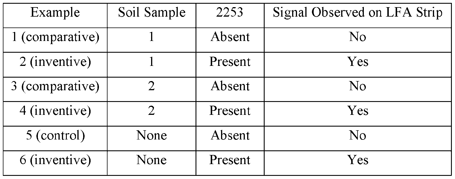 ere were c ear an s on t e str ps w en was present as compared to when 2253 was absent, regardless of soil type. Thus, background signals did not present a problem when detecting the presence or absence of a polypeptide involved in nitrogen fixation. Example 18. Determining the sensitivity of the polyclonal LFA The 2253 microbe was grown from a single colony in 5 mL media SOB agar plates for 20 hr at 30 ^C. Then 500 µL of overnight culture was transferred to a 1.5 mL tube, vortexed down to pellet the cells, and the supernatant was removed. The 2253 microbe was spiked into B-PER™ buffer at approximately 1e8 cells/mL and serial dilutions were completed down to 1e2 cells/mL. The concentrations tested were: 1e8 cells/mL, 1e7 cells/mL, 1e6 cells/mL, 1e5 cells/mL, 1e4 cells/mL, 1e3 cells/mL, and 1e2 cells/mL. The tip of an LFA strip was submerged into each solution for approximately 20 seconds while the liquid traveled up the strip. Then, the strip was removed while the reaction occurred (about 10 min).
The results observed from the LFA strips demonstrated that the LFA was consistently sensitive to the 2253 microbe and a reaction clearly occurred down to 1e4 cells/ml (5e2 to cells/strip). Particular embodiments of the invention have been described. Other embodiments are within the scope of the following claims. For example, the steps recited in the claims, described in the specification, or depicted in the figures can be performed in a different order and still achieve desirable results. In some embodiments, multitasking and parallel processing may be advantageous. OTHER EMBODIMENTS It is to be understood that while the invention has been described in conjunction with the detailed description thereof, the foregoing description is intended to illustrate and not limit the scope of the invention, which is defined by the scope of the appended claims. Other aspects, advantages, and modifications are within the scope of the following claims.
ere were c ear an s on t e str ps w en was present as compared to when 2253 was absent, regardless of soil type. Thus, background signals did not present a problem when detecting the presence or absence of a polypeptide involved in nitrogen fixation. Example 18. Determining the sensitivity of the polyclonal LFA The 2253 microbe was grown from a single colony in 5 mL media SOB agar plates for 20 hr at 30 ^C. Then 500 µL of overnight culture was transferred to a 1.5 mL tube, vortexed down to pellet the cells, and the supernatant was removed. The 2253 microbe was spiked into B-PER™ buffer at approximately 1e8 cells/mL and serial dilutions were completed down to 1e2 cells/mL. The concentrations tested were: 1e8 cells/mL, 1e7 cells/mL, 1e6 cells/mL, 1e5 cells/mL, 1e4 cells/mL, 1e3 cells/mL, and 1e2 cells/mL. The tip of an LFA strip was submerged into each solution for approximately 20 seconds while the liquid traveled up the strip. Then, the strip was removed while the reaction occurred (about 10 min).
The results observed from the LFA strips demonstrated that the LFA was consistently sensitive to the 2253 microbe and a reaction clearly occurred down to 1e4 cells/ml (5e2 to cells/strip). Particular embodiments of the invention have been described. Other embodiments are within the scope of the following claims. For example, the steps recited in the claims, described in the specification, or depicted in the figures can be performed in a different order and still achieve desirable results. In some embodiments, multitasking and parallel processing may be advantageous. OTHER EMBODIMENTS It is to be understood that while the invention has been described in conjunction with the detailed description thereof, the foregoing description is intended to illustrate and not limit the scope of the invention, which is defined by the scope of the appended claims. Other aspects, advantages, and modifications are within the scope of the following claims.
Claims
WHAT IS CLAIMED IS: 1. A method of determining the presence or absence of a polypeptide involved in nitrogen fixation in a rhizosphere of a non-leguminous plant, comprising: (a) contacting a sample of soil from the rhizosphere with a lysis buffer, thereby producing a solution; (b) contacting the solution with a sample-receiving zone of a substrate, wherein the substrate further comprises a detection zone comprising a reactive agent that, directly or indirectly, produces a signal based on the presence or absence of the polypeptide involved in nitrogen fixation once the solution contacts the detection zone; (c) detecting the signal produced by the reactive agent for a given time period after the solution contacts the detection zone; and (d) determining the presence or absence of the polypeptide involved in nitrogen fixation in the solution based on detection of the signal.
2. The method of claim 1, wherein the polypeptide involved in nitrogen fixation is selected from the group consisting of: nifH, nifD, and nifK.
3. The method of claim 2, wherein the polypeptide involved in nitrogen fixation is nifH.
4. The method of claim 2, wherein the polypeptide involved in nitrogen fixation is nifD.
5. The method of claim 2, wherein the polypeptide involved in nitrogen fixation is nifK.
6. The method of any one of claims 1-5, wherein the reactive agent is an antibody or antigen-binding fragment of an antibody.
7. The method of claim 6, wherein the antibody is a monoclonal antibody.
8. The method of claim 6, wherein the antibody is a polyclonal antibody.
9. The method of any one of claims 1-8, wherein the method further comprises: comparing the detected signal to a signal produced using a reference sample.
10. The method of any one of claims 1-9, wherein step (c) comprises detecting the signal produced by the reactive agent about 5 seconds to about 1 hour after the solution contacts the detection zone.
11. The method of any one of claims 1-10, wherein the lysis buffer water, at least one detergent, and one or more of a salt, an organic acid, a base, a chelating agent, an enzyme, a protease inhibitor, a sugar, and a reducing agent.
12. The method of any one of claims 1-11, wherein the method further comprises: determining the amount of nitrogen in the rhizosphere.
13. The method of any one of claims 1-12, wherein the method further comprises determining the nitrogen status of the non-leguminous plant comprising: (a) determining the chlorophyll content of the non-leguminous plant; (b) determining the biomass of the non-leguminous plant; (c) normalizing the determined biomass and the determined chlorophyll content for the plant; and (d) determining plant nitrogen status of the plant using the normalized chlorophyll content (CC) and the normalized biomass (PB) of the plant.
14. The method of claim 13, wherein the nitrogen status of the non-leguminous plant is determined in step (d) using Formula I: Plant Nitrogen Status (NS) = ^(PB) + ^(CC).
15. The method of claim 14, wherein ^ is 0.80.
16. The method of claim 14 or 15, wherein ^ is 0.20.
17. The method of any one of claims 1-16, wherein the non-leguminous plant is selected from the group consisting of: maize, rice, wheat, barley, sorghum, millet, oats, rye, triticale, buckwheat, sugar cane, onions, tomatoes, strawberries, and asparagus.
18. The method of any one of claims 1-17, wherein one or more of the non- leguminous plant, the rhizosphere of the non-leguminous plant, soil in which the non- leguminous plant was cultivated, or a seed from which the non-leguminous plant was grown was previously contacted with one or more genetically engineered bacteria comprising a genetic variation in a nitrogen fixation gene or a nitrogen-assimilation gene.
19. The method of claim 18, wherein the one or more bacteria is of a genus independently selected from Kosakonia, Rahnella, Klebsiella, Paenibacillus, Paraburkholderia, and Herbaspirillum.
20. The method of claim 19, wherein the one or more bacteria comprise at least one strain selected from a group consisting of Klebsiella variicola and Kosakonia sacchari.
21. The method of any one of claims 1-20, wherein the method further comprises: applying a composition comprising one or more bacteria to one or more of the non-leguminous plant, to the rhizosphere of the non-leguminous plant, to the soil in which the non-leguminous plant is cultivated or to the surface of the seed of the non- leguminous plant.
22. The method of claim 21, wherein the one or more bacteria is a genetically engineered bacterium comprising a genetic variation in a nitrogen fixation gene or a nitrogen-assimilation gene.
23. The method of claim 21 or 22, wherein the one or more bacteria is of a genus independently selected from Kosakonia, Rahnella, Klebsiella, Paenibacillus, Paraburkholderia, and Herbaspirillum.
24. The method of any one of claims 21-23, wherein the one or more bacteria comprise at least one strain selected from a group consisting of Klebsiella variicola and Kosakonia sacchari.
25. The method of any one of claims 21-24, wherein the method further comprises applying a nitrogen-containing fertilizer to one or more of the non-leguminous plant, the rhizosphere of the non-leguminous plant, and soil in which the non-leguminous plant is cultivated.
26. A lateral flow assay system for determining the presence or absence of a polypeptide involved in nitrogen fixation in a sample, comprising: a substrate comprising a sample-receiving zone and a detection zone, wherein the detection zone comprises a reactive agent that produces a signal based on the presence or absence of a nitrogen fixation polypeptide involved in nitrogen fixation in a solution contacted with the sample-receiving zone of the substrate.
27. The lateral flow assay system of claim 26, wherein the polypeptide involved in nitrogen fixation is selected from the group consisting of: nifH, nifD, and nifK.
28. The lateral flow assay system of claim 26 or 27, wherein the reactive agent is an antibody or antigen-binding fragment of an antibody.
29. The lateral flow assay system of claim 28, wherein the antibody is a monoclonal antibody.
30. The lateral flow assay system of claim 28, wherein the antibody is a polyclonal antibody.
Applications Claiming Priority (2)
| Application Number | Priority Date | Filing Date | Title |
|---|---|---|---|
| US202363529025P | 2023-07-26 | 2023-07-26 | |
| US63/529,025 | 2023-07-26 |
Publications (2)
| Publication Number | Publication Date |
|---|---|
| WO2025024750A2 true WO2025024750A2 (en) | 2025-01-30 |
| WO2025024750A3 WO2025024750A3 (en) | 2025-03-06 |
Family
ID=92494607
Family Applications (1)
| Application Number | Title | Priority Date | Filing Date |
|---|---|---|---|
| PCT/US2024/039701 Pending WO2025024750A2 (en) | 2023-07-26 | 2024-07-26 | Assessing nitrogenase proteins in rhizosphere to infer microbial functioning |
Country Status (1)
| Country | Link |
|---|---|
| WO (1) | WO2025024750A2 (en) |
Cited By (6)
| Publication number | Priority date | Publication date | Assignee | Title |
|---|---|---|---|---|
| US12421519B2 (en) | 2019-01-07 | 2025-09-23 | Pivot Bio, Inc. | Plant colonization assays using natural microbial barcodes |
| CN120758421A (en) * | 2025-07-28 | 2025-10-10 | 广东省农业科学院植物保护研究所 | A strain of Paenibacillus polymyxa S437 and its application |
| US12471599B2 (en) | 2018-06-27 | 2025-11-18 | Pivot Bio, Inc. | Agricultural compositions comprising remodeled nitrogen fixing microbes |
| US12478068B2 (en) | 2020-05-01 | 2025-11-25 | Pivot Bio, Inc. | Stable liquid formulations for nitrogen-fixing microorganisms |
| US12612639B2 (en) | 2018-06-27 | 2026-04-28 | Pivot Bio, Inc. | Guided microbial remodeling, a platform for the rational improvement of microbial species for agriculture |
| US12612669B2 (en) | 2019-04-25 | 2026-04-28 | Pivot Bio, Inc. | High-throughput methods for isolating and characterizing ammonium-excreting mutant libraries generated by chemical mutagenesis |
Citations (12)
| Publication number | Priority date | Publication date | Assignee | Title |
|---|---|---|---|---|
| US7419821B2 (en) | 2002-03-05 | 2008-09-02 | I-Stat Corporation | Apparatus and methods for analyte measurement and immunoassay |
| US9488585B2 (en) | 2011-12-23 | 2016-11-08 | Abbott Point Of Care Inc. | Reader devices for optical and electrochemical test devices |
| WO2017011602A1 (en) | 2015-07-13 | 2017-01-19 | Pivot Bio, Inc. | Methods and compositions for improving plant traits |
| WO2017062412A1 (en) | 2015-10-05 | 2017-04-13 | Massachusetts Institute Of Technology | Nitrogen fixation using refactored nif clusters |
| WO2018132774A1 (en) | 2017-01-12 | 2018-07-19 | Pivot Bio, Inc. | Methods and compositions for improving plant traits |
| WO2019084342A1 (en) | 2017-10-25 | 2019-05-02 | Pivot Bio, Inc. | Gene targets for nitrogen fixation targeting for improving plant traits |
| US20190376970A1 (en) | 2008-05-20 | 2019-12-12 | Rapid Pathogen Screening, Inc. | Method and Device for Combined Detection of Viral and Bacterial Infections |
| WO2020132632A2 (en) | 2018-12-21 | 2020-06-25 | Pivot Bio, Inc. | Methods, compositions, and media for improving plant traits |
| WO2021221690A1 (en) | 2020-05-01 | 2021-11-04 | Pivot Bio, Inc. | Modified bacterial strains for improved fixation of nitrogen |
| WO2021222567A2 (en) | 2020-05-01 | 2021-11-04 | Pivot Bio, Inc. | Modified bacterial strains for improved fixation of nitrogen |
| WO2021231449A2 (en) | 2020-05-13 | 2021-11-18 | Pivot Bio, Inc. | De-repression of nitrogen fixation in gram-positive microorganisms |
| US11693011B2 (en) | 2020-12-14 | 2023-07-04 | Inbios International, Inc. | Neutralizing antibody immunoassays |
Family Cites Families (3)
| Publication number | Priority date | Publication date | Assignee | Title |
|---|---|---|---|---|
| MX2020004343A (en) * | 2017-10-25 | 2021-01-08 | Pivot Bio Inc | Methods and compositions for improving engineered microbes that fix nitrogen. |
| CN111944832B (en) * | 2020-08-28 | 2022-11-29 | 上海市农业科学院 | Self-generated nitrogen fixation gene for plants, nitrogenase expression cassette, preparation method and application thereof |
| KR102385330B1 (en) * | 2021-01-04 | 2022-04-11 | 베트올 (주) | Simultaneous diagnostic method and Simultaneous diagnostic kit for the Erwinia Carotovora and Phytophthora Infestans in soil using semi-quantitative lateral flow immunoassay |
-
2024
- 2024-07-26 WO PCT/US2024/039701 patent/WO2025024750A2/en active Pending
Patent Citations (12)
| Publication number | Priority date | Publication date | Assignee | Title |
|---|---|---|---|---|
| US7419821B2 (en) | 2002-03-05 | 2008-09-02 | I-Stat Corporation | Apparatus and methods for analyte measurement and immunoassay |
| US20190376970A1 (en) | 2008-05-20 | 2019-12-12 | Rapid Pathogen Screening, Inc. | Method and Device for Combined Detection of Viral and Bacterial Infections |
| US9488585B2 (en) | 2011-12-23 | 2016-11-08 | Abbott Point Of Care Inc. | Reader devices for optical and electrochemical test devices |
| WO2017011602A1 (en) | 2015-07-13 | 2017-01-19 | Pivot Bio, Inc. | Methods and compositions for improving plant traits |
| WO2017062412A1 (en) | 2015-10-05 | 2017-04-13 | Massachusetts Institute Of Technology | Nitrogen fixation using refactored nif clusters |
| WO2018132774A1 (en) | 2017-01-12 | 2018-07-19 | Pivot Bio, Inc. | Methods and compositions for improving plant traits |
| WO2019084342A1 (en) | 2017-10-25 | 2019-05-02 | Pivot Bio, Inc. | Gene targets for nitrogen fixation targeting for improving plant traits |
| WO2020132632A2 (en) | 2018-12-21 | 2020-06-25 | Pivot Bio, Inc. | Methods, compositions, and media for improving plant traits |
| WO2021221690A1 (en) | 2020-05-01 | 2021-11-04 | Pivot Bio, Inc. | Modified bacterial strains for improved fixation of nitrogen |
| WO2021222567A2 (en) | 2020-05-01 | 2021-11-04 | Pivot Bio, Inc. | Modified bacterial strains for improved fixation of nitrogen |
| WO2021231449A2 (en) | 2020-05-13 | 2021-11-18 | Pivot Bio, Inc. | De-repression of nitrogen fixation in gram-positive microorganisms |
| US11693011B2 (en) | 2020-12-14 | 2023-07-04 | Inbios International, Inc. | Neutralizing antibody immunoassays |
Non-Patent Citations (18)
| Title |
|---|
| ABENDROTH ET AL.: "Corn Growth and Development", IOWA STATE UNIV. EXTENSION PUBLICATION PMR1009, 2011 |
| ABENDROTH ET AL.: "Corn growth and development", IOWA STATE UNIVERSITY EXTENSION. PMR 1009, 2011 |
| BARILLOT ET AL., ANNALS MICROBIOL., vol. 63, 2013, pages 471 - 476 |
| BARILLOT ET AL., ANNALS OF MICROBIOL, vol. 63, 2013, pages 471 - 476 |
| BENDER ET AL., AGRON. J., vol. 105, 2013, pages 161 - 170 |
| BOOMSMA ET AL., AGRON. J., vol. 101, 2009, pages 1426 - 1452 |
| FANG ET AL., J. PHARM. BIOMED. ANAL., vol. 56, 2011, pages 1035 - 1040 |
| FUNG ET AL., ANAL. CHIM. ACTA, vol. 634, 2009, pages 89 - 95 |
| GITELSON ET AL., REMOTE SENS. ENVIRON., vol. 69, no. 3, 1999, pages 296 - 302 |
| HOOD-NOWOTNY ET AL., SOIL SCI. SOC. AMER. JOUR., vol. 74, no. 3, 2010, pages 1018 - 1027 |
| KOCZULA ET AL., ESSAYS IN BIOCHEMISTRY, vol. 60, 2016, pages 111 - 120 |
| LEUNG ET AL., J. IMMUNOL. METHODS, vol. 336, 2008, pages 30 - 36 |
| PORRA ET AL., BIOCHIM. BIOPHYS. ACTA, vol. 975, no. 3, 1989, pages 384 - 394 |
| TOLLENAAR ET AL.: "Physiology and modeling kernel set in maize. Proc. of a Symp.", 18 October 1998, BALTIMORE, MD., article "Physiological parameters associated with differences in kernel set among maize hybrids", pages: 115 - 130 |
| WORKMAN ET AL., J. VIROL. METHODS, vol. 160, 2009, pages 14 - 21 |
| XU ET AL., ANAL. CHEM., vol. 86, 2014, pages 5611 - 5614 |
| YEN ET AL., LAB CHIP, vol. 15, 2015, pages 1638 - 1641 |
| ZIMMERMAN ET AL., METHOD MANUAL: DETERMINATION OF CARBON AND NITROGEN IN SEDIMENTS AND PARTICULATES OF ESTUARINE/COASTAL WATERS USING ELEMENTAL ANALYSIS, 1997 |
Cited By (8)
| Publication number | Priority date | Publication date | Assignee | Title |
|---|---|---|---|---|
| US12471599B2 (en) | 2018-06-27 | 2025-11-18 | Pivot Bio, Inc. | Agricultural compositions comprising remodeled nitrogen fixing microbes |
| US12612639B2 (en) | 2018-06-27 | 2026-04-28 | Pivot Bio, Inc. | Guided microbial remodeling, a platform for the rational improvement of microbial species for agriculture |
| US12610956B2 (en) | 2018-06-27 | 2026-04-28 | Pivot Bio, Inc. | Agricultural compositions comprising remodeled nitrogen fixing microbes |
| US12421519B2 (en) | 2019-01-07 | 2025-09-23 | Pivot Bio, Inc. | Plant colonization assays using natural microbial barcodes |
| US12612669B2 (en) | 2019-04-25 | 2026-04-28 | Pivot Bio, Inc. | High-throughput methods for isolating and characterizing ammonium-excreting mutant libraries generated by chemical mutagenesis |
| US12478068B2 (en) | 2020-05-01 | 2025-11-25 | Pivot Bio, Inc. | Stable liquid formulations for nitrogen-fixing microorganisms |
| CN120758421A (en) * | 2025-07-28 | 2025-10-10 | 广东省农业科学院植物保护研究所 | A strain of Paenibacillus polymyxa S437 and its application |
| CN120758421B (en) * | 2025-07-28 | 2026-02-24 | 广东省农业科学院植物保护研究所 | A strain of Bacillus polymyxa S437 and its application |
Also Published As
| Publication number | Publication date |
|---|---|
| WO2025024750A3 (en) | 2025-03-06 |
Similar Documents
| Publication | Publication Date | Title |
|---|---|---|
| WO2025024750A2 (en) | Assessing nitrogenase proteins in rhizosphere to infer microbial functioning | |
| US20250137985A1 (en) | Assessing relative plant nitrogen in a field environment | |
| US11819027B2 (en) | Streptomyces endophyte compositions and methods for improved agronomic traits in plants | |
| US20250369878A1 (en) | Measurement of nitrogen fixation and incorporation | |
| Chen et al. | Root ethylene mediates rhizosphere microbial community reconstruction when chemically detecting cyanide produced by neighbouring plants | |
| US12612669B2 (en) | High-throughput methods for isolating and characterizing ammonium-excreting mutant libraries generated by chemical mutagenesis | |
| Kandeler et al. | Response of soil microbial biomass and enzyme activities to the transient elevation of carbon dioxide in a semi-arid grassland | |
| US11751515B2 (en) | Endophyte compositions and methods for improvement of plant traits in plants of agronomic importance | |
| ES2752451T3 (en) | Microbes that promote the growth of plants and their uses | |
| Nannipieri et al. | Effects of root exudates in microbial diversity and activity in rhizosphere soils | |
| Rho et al. | Endophytes alleviate the elevated CO2-dependent decrease in photosynthesis in rice, particularly under nitrogen limitation | |
| BR112016030458B1 (en) | METHOD FOR PREPARING A SYNTHETIC COMBINATION COMPRISING A CORN SEED AND AN ENDOPHYTIC BACTERIAL POPULATION | |
| US20250359554A1 (en) | Plant microbial preparations, compositions and formulations comprising same and uses thereof | |
| Lagomarsino et al. | Labile substrates quality as the main driving force of microbial mineralization activity in a poplar plantation soil under elevated CO2 and nitrogen fertilization | |
| Wagner-Riddle et al. | Improving nitrogen use efficiency in crop production | |
| Chandramohan et al. | Sulphate and sulphurous acid alter the relative susceptibility of wheat to P haeosphaeria nodorum and M ycosphaerella graminicola | |
| WO2025254827A1 (en) | High throughput real-time in-planta assay of microbial nitrogen fixation activity | |
| Liang | The Effect of Freeze-Thaw Cycles on Microbial Resilience Along a Crop Biodiversity Gradient | |
| Knox et al. | Cotton cultivar selection impacts on microbial diversity and function. | |
| Groebner | Combining soil health and fertility measurements to improve the accuracy of predicting corn grain yield responses to P and K fertilization | |
| Rae | Measuring Germination: The Radicand Germination Index. & A Biostimulant Seed Treatment: Mechanism and Optimization. | |
| Redfearn et al. | WICS Conference 2024: Creating Connections Together: Agenda and Abstracts | |
| D’agostini et al. | Silicon isotopic fractionation under water stress in Sorghum bicolor: evidence from in situ morphotype-specific phytolith analysis | |
| Hoegenauer | Diagnosing Excess Nitrogen in Rice Using Post-Season Tissue Samples | |
| Guinagui et al. | Effect of Rice yellow mottle virus, Sobemovirus on the Contents of NPK Ca and Mg in Leaves of Infected Rice |
Legal Events
| Date | Code | Title | Description |
|---|---|---|---|
| 121 | Ep: the epo has been informed by wipo that ep was designated in this application |
Ref document number: 24758921 Country of ref document: EP Kind code of ref document: A2 |
|
| NENP | Non-entry into the national phase |
Ref country code: DE |