WO2021031781A1 - Method and device for calibrating projection image and projection device - Google Patents
Method and device for calibrating projection image and projection device Download PDFInfo
- Publication number
- WO2021031781A1 WO2021031781A1 PCT/CN2020/103587 CN2020103587W WO2021031781A1 WO 2021031781 A1 WO2021031781 A1 WO 2021031781A1 CN 2020103587 W CN2020103587 W CN 2020103587W WO 2021031781 A1 WO2021031781 A1 WO 2021031781A1
- Authority
- WO
- WIPO (PCT)
- Prior art keywords
- projection
- plane
- information
- exit plane
- rotation matrix
- Prior art date
- Legal status (The legal status is an assumption and is not a legal conclusion. Google has not performed a legal analysis and makes no representation as to the accuracy of the status listed.)
- Ceased
Links
Images


Classifications
-
- H—ELECTRICITY
- H04—ELECTRIC COMMUNICATION TECHNIQUE
- H04N—PICTORIAL COMMUNICATION, e.g. TELEVISION
- H04N9/00—Details of colour television systems
- H04N9/12—Picture reproducers
- H04N9/31—Projection devices for colour picture display, e.g. using electronic spatial light modulators [ESLM]
- H04N9/3179—Video signal processing therefor
- H04N9/3185—Geometric adjustment, e.g. keystone or convergence
-
- H—ELECTRICITY
- H04—ELECTRIC COMMUNICATION TECHNIQUE
- H04N—PICTORIAL COMMUNICATION, e.g. TELEVISION
- H04N9/00—Details of colour television systems
- H04N9/12—Picture reproducers
- H04N9/31—Projection devices for colour picture display, e.g. using electronic spatial light modulators [ESLM]
Definitions
- the present application relates to the field of image processing technology, and more specifically, to a projection image calibration method, device, projection equipment, and storage medium.
- this application proposes a projection image calibration method, device, projection equipment, and storage medium to improve the above problems.
- an embodiment of the present application provides a projection image calibration method, the method includes: acquiring the spatial depth information of the projection image to be calibrated collected by three or more ranging sensors located on the exit plane, and the spatial depth The information is the distance information from the exit plane to the projection plane formed by the ranging sensor; the projection plane information is determined based on the spatial depth information and the relative position relationship between the ranging sensors; the projection plane relative to the exit plane is obtained based on the exit plane information and the projection plane information According to the rotation matrix, the projection screen of the projected image to be calibrated is transformed into perspective to adjust the projection screen to the target shape.
- an embodiment of the present application provides a projection image calibration device that runs on a projection device.
- the device includes: a data acquisition unit for acquiring data collected by three or more ranging sensors located on the exit plane.
- the spatial depth information of the projected image to be calibrated is the distance information from the projection plane to the projection plane formed by the ranging sensor; the data processing unit is used to determine the projection plane based on the spatial depth information and the relative position relationship between the ranging sensors The data processing unit is also used to obtain the rotation matrix of the projection plane relative to the exit plane based on the exit plane information and the projection plane information; the projection unit is used to perform perspective transformation on the projection screen of the projected image to be calibrated according to the rotation matrix to project The picture is adjusted to the target shape.
- an embodiment of the present application provides a projection device, including a data acquisition module, a projection module, one or more processors, and a memory; one or more programs are stored in the memory and configured to be The one or more processors execute, and the one or more programs are configured to execute the method described in the first aspect.
- an embodiment of the present application provides a computer-readable storage medium having a program code stored in the computer-readable storage medium, wherein the method described in the first aspect is executed when the program code is running.
- the projection image calibration method, device, projection equipment, and storage medium provided by the present application obtain the spatial depth information of the projection image to be calibrated collected by three or more range-finding sensors located on the exit plane, and the spatial depth information is Distance information from the exit plane to the projection plane formed by the ranging sensor; then determine the projection plane information based on the spatial depth information and the relative position relationship between the ranging sensors; then obtain the projection plane relative to the exit plane based on the exit plane information and the projection plane information According to the rotation matrix, the projection screen of the projection image to be calibrated is transformed into perspective to adjust the projection screen to the target shape.
- the rotation matrix of the projection plane relative to the projection plane is obtained based on the exit plane information and the projection plane information of the exit plane where the ranging sensor is located, and then when the rotation matrix is acquired, the projection image is to be calibrated according to the rotation matrix.
- the projection image of the camera is transformed into perspective, so that the automatic correction of the projected image can be completed quickly and the user experience is enhanced.
- Fig. 1 shows a method flowchart of a projection image calibration method proposed in an embodiment of the present application.
- Fig. 2 shows a method flowchart of a projection image calibration method proposed by another embodiment of the present application.
- FIG. 3 shows a diagram of an example projection of the projection device provided by the embodiment of the present application.
- FIG. 4 shows an example diagram of a projection mode of the projection device provided by the embodiment of the present application.
- Fig. 5 shows an example diagram of another projection mode of the projection device provided by the embodiment of the present application.
- FIG. 6 shows a method flowchart of the method of step S260 in FIG. 2.
- FIG. 7 shows a method flowchart of the method of step S263 in FIG. 3.
- FIG. 8 shows a schematic diagram of the rotation angle between the emission plane of the projection light of the projection device provided by the embodiment of the present application and the plane where the projection area is located.
- Fig. 9 shows a structural block diagram of a projection image calibration device proposed in an embodiment of the present application.
- Fig. 10 shows a structural block diagram of a projection device of the present application for executing a projection image calibration method according to an embodiment of the present application.
- Fig. 11 shows a storage unit for storing or carrying program codes for implementing a projection image calibration method according to an embodiment of the present application.
- the keystone correction of the vertical direction of the projected image can be achieved by completely manual adjustment, but this way has randomness and contingency, which affects the calibration efficiency of the projected image.
- the tilt angle can be obtained through the gyroscope, and then the automatic keystone correction in the vertical direction of the projected image is performed.
- the user experience of this method is much improved, but the left and right horizontal calibration is still not possible.
- four-point keystone correction can be used to calibrate the distortion of the projected image. This method can be corrected by manually adjusting the four vertices of the projected image to the correct position.
- the inventor proposes that the present application can make it possible to determine the projection plane information based on the spatial depth information and the relative position relationship between the ranging sensors when the spatial depth information is acquired, and then based on the ranging
- the exit plane information of the exit plane where the sensor is located and the projection plane information obtain the rotation matrix of the projection plane relative to the exit plane. Then, when the rotation matrix is acquired, the projection screen of the projection image to be calibrated is transformed according to the rotation matrix, making it fast The projected image is automatically corrected to enhance the user experience.
- FIG. 1 is a method flowchart of a projection image calibration method provided by an embodiment of the application.
- the method of this embodiment can be executed by a device for calibrating a projected image.
- the device can be implemented by hardware and/or software, and can generally be integrated in a projection device provided with at least 3 range-finding sensors on the same plane.
- the projection equipment can include devices with projection functions such as laser TVs, projectors, and micro-projectors. It can also be a computer system that connects to a device with projection function and uses the distance measuring sensor of the device, such as a personal computer connected to a projection device, Laptops, tablets, smart phones, etc.
- the execution of this method depends on a computer program, which can run on a computer system, and the computer system can be an operating system of the projection device. It should be noted that the projection direction of the projection device in the embodiment of the present application is not limited, and may be rear projection or front projection.
- the method includes:
- Step S110 Obtain the spatial depth information of the projected image to be calibrated collected by three or more ranging sensors located on the exit plane.
- the spatial depth information in the embodiment of the present application can be understood as the spatial distance information of the projection area corresponding to the projection device distance along the projection direction of the projection device.
- the spatial distance information may include the distance, direction, and tilt angle difference between the projection device and the projection area.
- the projection equipment may be a projector or a laser projector or other equipment with projection function, which is not limited here.
- the spatial depth information may include the distance between the projection area for displaying the projection image to be calibrated and the projection device.
- the projected image to be calibrated can be understood as an image with image distortion after being projected onto the projection area by the projection device.
- the projection device can obtain the change rule of the pixel points of the projected image.
- the projection device can obtain the projection image corresponding to the image data, and then determine the position of each pixel row according to the projected image, and then obtain the horizontal line length sum of each pixel row in the projection image The horizontal distortion length can then calculate the corrected pixel amount of the projected image according to the horizontal distortion length and the horizontal line length, and then it can be determined whether there is pixel distortion in the projected image.
- the image data can be pre-stored (for example, the audio and video data that needs to be projected is copied to the projection device for storage) or instant storage (for example, the mobile hard disk storing the audio and video data that needs to be projected is inserted in the projection device Above), the specific storage method is not limited. It is understandable that if image distortion is detected, these projected images with image distortion can be used as the projected images to be calibrated.
- the projection device may acquire the spatial depth information of the projection image to be calibrated collected by three or more distance measuring sensors located on the exit plane.
- the distance measuring sensor can be configured in the projection device (for example, installed on the light-emitting surface of the projection device, which can be understood as the projection plane of the projection light of the projection device) for measuring the projection area of the projected image to be calibrated and the projection device
- Various distance sensors for distance such as ToF (Time of Flight, Time of Flight) laser distance sensor, infrared distance sensor, ultrasonic distance sensor, etc.
- the ToF laser ranging sensor can transmit and receive laser light with a wavelength of 940nm to measure the space flight time difference and obtain the target distance. It has outstanding resistance to ambient light interference and can be applied to bright environments. It should be noted that the embodiments of the present application do not limit the specific types of distance measurement sensors. For example, it may be a (laser) distance measurement sensor with depth information measurement function that can be realized by existing or future technologies, which can meet the requirements for collecting and calibrating. It is sufficient to project the spatial depth information of the image. Subsequent embodiments of this application will use a ToF laser ranging sensor as an example for description.
- the ToF laser distance measuring sensor can be installed facing the direction of the projection device (ie, forward installation), so that the ToF laser distance measuring sensor can be used Collect the spatial depth information of the projected image to be calibrated.
- Step S120 Determine projection plane information based on the spatial depth information and the relative position relationship between the ranging sensor.
- the projection plane refers to the plane where the image (or image) projected by the projection device is located.
- the projection plane For example, if the projector in the conference room puts the PPT presentation on the projection screen, then the plane where the projection screen (that is, the projection area) is located at this time is the projection plane. It is understandable that, in order to facilitate the calibration of the pixel distortion of the projected image, after the spatial depth information of the projected image to be calibrated collected by the ranging sensor is obtained, it can be based on the spatial depth information and multiple (ie three or more) The relative position relationship between the ranging sensors obtains the projection plane information of the plane where the projection area is located.
- the projection plane information can be expressed by a projection plane equation.
- the installation position of the distance measuring sensor is fixed, then the respective position coordinates of multiple distance measuring sensors can be obtained, and then the projection plane equation representing the projection plane information can be obtained based on the spatial depth information and the position coordinates of the distance measuring sensor .
- the projection plane includes the projection area, and the projection area is usually fitted to the projection plane, that is, the distance between the projection area and the projection plane (it can be the vertical distance) can be ignored, so the obtained projection plane equation As the equation of the projection plane.
- the projection plane equation is an equation that characterizes the plane of the projection area in the specified coordinate system.
- the designated coordinate system represents the coordinate system of the projection device. It can be understood that, for a distance measuring sensor installed in a projection device, for example, for a ToF laser distance measuring sensor installed on the projection device in a forward direction, the plane where the ToF laser distance measuring sensor is installed on the projection device can be used as the starting coordinate plane.
- the projection plane equation is an equation that characterizes the plane of the projection area in the specified coordinate system.
- the projection can be determined according to the position where the projection device is installed with multiple ToF ranging sensors and the obtained projection light exit plane of 3 or more projection devices to the plane where the projection area is located (that is, the projection plane). Plane equation. By obtaining the projection plane equation, it is convenient to subsequently calculate the rotation matrix between the plane where the projection area is located (the projection plane) and the projection light exit plane of the projection device.
- Step S130 Obtain a rotation matrix of the projection plane relative to the exit plane based on the exit plane information and the projection plane information.
- the exit plane information includes the exit plane equation.
- the coordinate system of the plane where the ToF laser ranging sensor is located is not fixed, that is, the ToF laser
- the coordinate system of the plane where the ranging sensor is located is the reference coordinate system.
- the exit plane equation can be obtained in advance according to the position of the ToF laser ranging sensor.
- the equation of the plane where the ToF laser ranging sensor is located (similarly, when different ToF laser ranging sensors are located on the same plane)
- the exit plane equation of the exit plane of the projection light of the projection device is calculated.
- the projection device in the process of delivering the image from the projection device to the projection area, the projection device (or the placement position of the projection device) cannot be completely parallel to the plane where the projection area is located, resulting in pixel displacement of the projected image, resulting in projection
- the image has pixel distortion. Therefore, in order to eliminate the projection error caused by such pixel distortion and enhance the visual effect of the projected image, the rotation matrix of the projection plane relative to the exit plane can be obtained based on the exit plane information and the projection plane information, that is to say , The rotation matrix can be used to eliminate the pixel distortion caused by the pixel displacement of the projected image.
- the rotation matrix of the projection plane relative to the exit plane can be calculated based on the exit plane equation and the projection plane equation, so that the automatic distortion calibration of the projected image to be calibrated can be performed based on the rotation matrix.
- Step S140 Perform perspective transformation on the projection image of the projection image to be calibrated according to the rotation matrix, so as to adjust the projection image to a target shape.
- the automatic distortion calibration can be realized by performing perspective transformation on the projection image of the projection image to be calibrated according to the above-mentioned rotation matrix.
- the perspective transformation can be understood as the correction of the pixel point displacement of the projection image of the projection image to be calibrated.
- the projection image of the projection image to be calibrated can be adjusted to the target shape. For example, adjust to a square rectangle.
- the specific shape of the target shape here is not limited, and can be any desired shape, for example, a square rectangle, a positive direction or a circle, etc., which can be set according to actual conditions.
- the projection image calibration method obtaineds the spatial depth information of the projected image to be calibrated collected by three or more ranging sensors located on the exit plane, and then based on the spatial depth information and the distance between the ranging sensors
- the relative position relationship determines the projection plane information, and then obtains the rotation matrix of the projection plane relative to the projection plane based on the exit plane information and the projection plane information, and then performs perspective transformation on the projection screen of the projected image to be calibrated according to the rotation matrix to adjust the projection screen to the target shape. It is realized that the rotation matrix of the projection plane relative to the emission plane is obtained based on the emission plane information of the emission plane where the distance measuring sensor is located and the projection plane information. Then, when the rotation matrix is obtained, the projection screen of the projection image to be calibrated is performed according to the rotation matrix.
- Perspective transformation enables rapid automatic correction of projected images and enhances user experience.
- FIG. 2 is a method flowchart of a projection image calibration method provided by another embodiment of this application.
- the method of this embodiment can be executed by a device for calibrating a projected image.
- the device can be implemented by hardware and/or software, and can generally be integrated into a projection device, which can include a laser TV, a projector, and a micro-projector. And other equipment with projection function.
- the execution of this method depends on a computer program, which can run on a computer system, and the computer system can be an operating system of the projection device.
- the projection direction of the projection device in the embodiment of the present application is not limited, and may be rear projection or front projection.
- the method includes:
- Step S210 Obtain the spatial depth information of the projection image to be calibrated collected by three or more ranging sensors located on the exit plane.
- Step S220 Obtain the position coordinates of the preset number of the distance measuring sensors provided on the projection device.
- the preset number in the embodiment of the present application may be 3 or more, and the positions where the preset number of distance measuring sensors are placed are not on the same straight line.
- the exit plane of the projection light of multiple projection devices can be obtained to the plane where the projection area is located (projection plane) the distance.
- a three-dimensional coordinate system can be constructed, and the three-dimensional coordinate system can be constructed with the projection point of the projection device as the origin; in another implementation, any of the planes on which the ToF laser ranging sensor can be placed can also be constructed. One point is the origin to construct a three-dimensional coordinate system, and then the position coordinates of each ToF laser ranging sensor in the constructed three-dimensional coordinate system are obtained.
- the ToF laser ranging sensor 103 is installed forwardly on the projection device 100 (the number of ToF laser ranging sensors is not limited here, and it can be 3 or more than 3).
- Figure 3 shows 3)
- the placement positions of the projection devices in the embodiments of the present application may be different, that is, the relationship between the emission plane of the projection light of the projection device and the plane (projection plane) where the projection area is located may be different.
- the projection device 100 may project in a direction directly facing the plane (projection plane) where the projection area is located.
- the normal line of the lens of the projection device 100 and The plane 101 where the projection area is located is vertical.
- the projection direction of the projection device 100 may also have a certain tilt angle to the plane 101 where the projection area is located.
- the normal line of the lens of the projection device 100 and the projection The plane 101 where the area is located may be non-vertical.
- this projection mode may be applied to an ultra-short-range laser TV.
- the projection mode shown in FIG. 5 is different in constructing the reference coordinate system of the projection light emission plane of the projection device.
- the distance between the exit plane of the projection light of the projection device and the plane where the projection area is located measured by the ToF laser distance measuring sensor, will also vary.
- the vertical distance between the projection light of the projection device and the plane of the projection area can be taken as The distance between the exit plane of the projection light of the projection device and the plane where the projection area is located.
- the distance from the vertical line of the projection plane of the projection light of the projection device to the plane where the projection area is located and the ToF laser ranging sensor (correspondingly, the number of ToF laser ranging sensors in this case
- the position coordinates of 3 or more and not on the same straight line) are used to obtain the equation of the plane where the projection area is located, that is, the projection plane equation, so as to facilitate the subsequent processing of the shadow image in the projection mode as shown in Figure 5. Distortion is automatically calibrated.
- Step S230 Determine an exit plane corresponding to the projection device based on the position coordinates.
- the exit plane corresponding to the projection device can be determined based on the position coordinates of the ToF laser ranging sensor, that is, the exit plane of the projection light of the projection device can be determined. For example, optionally, if the position coordinates of the ToF laser ranging sensor are obtained as (x1, y1, 0), (x2, y2, 0), (x3, y3, 0), then it can be determined that they correspond to the projection device
- the distance can be determined to install the ToF laser ranging
- Step S240 Obtain projection plane information based on the exit plane and the spatial depth information.
- the equation of the plane where the projection area is located (ie, the projection plane equation) can be calculated according to the distance from the exit plane of the projection light of the multiple projection devices to the plane where the projection area is located and the position coordinates of the multiple ToF laser ranging sensors.
- the coordinates of the above projection points can be obtained as (x1, y1, z1), (x2, y2, z2), (x3, y3, z3), ... (xn, yn, zn).
- the least square method may be used in this embodiment to fit the projection plane equation of the plane where the projection area is located.
- the coefficients A, B, and C are the obtained fitting plane parameters. Therefore, the projection plane equation of the plane where the projection area is located in the coordinate system of the projection device can be obtained as:
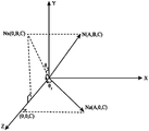
- the normal vector can be determined as N(A, B, C).
- Step S250 Obtain a rotation angle of the projection plane relative to the exit plane based on the exit plane information and the projection plane information.
- the direction of is taken as the positive direction of the Z axis, and its normal vector can be determined as n(0, 0, 1).
- the rotation angle of the projection plane relative to the exit plane can be obtained based on the exit plane equation and the projection plane equation, so that the rotation matrix of the projection plane relative to the exit plane can be obtained according to the rotation angle, and then the correction can be achieved. Automatic calibration of the projected image.
- Step S260 Calculate the rotation matrix of the projection plane relative to the exit plane based on the rotation angle.
- step S260 may include:
- Step S261 Obtain the normal vector of the projection plane.
- the normal vector of the projection plane is the normal vector of the plane where the projection area is located.
- the rotation matrix between the two planes can be obtained by obtaining the rotation matrix between the normal vectors of the two planes, and thus the normal vector of the projection plane can be obtained.
- the normal vector of the projection plane may be N(A, B, C).
- Step S262 Obtain the normal vector of the exit plane.
- the normal vector of the exit plane may be n(0, 0, 1).
- Step S263 Obtain the rotation angle of the normal vector of the exit plane transformed to the normal vector of the projection plane.
- step S263 may include:
- Step S2631 Obtain the angle between the projection vector of the normal vector of the projection plane on the two-dimensional plane and the positive direction of the corresponding coordinate axis.
- the two-dimensional plane refers to the surface projected by the normal vector N (A, B, C), and the corresponding coordinate axis can be understood as the starting coordinate axis of the surface projected by N (A, B, C), for example, suppose The plane projected by the normal vector N (A, B, C) is the XOY plane, then the X axis can be used as the corresponding coordinate axis of the projection vector of the normal vector N (A, B, C) on the two-dimensional plane (XOY plane) . Then, it can be understood that the positive direction of the corresponding coordinate axis can be understood as the positive direction of the initial coordinate axis. For example, the positive direction of the X axis can be taken as the positive direction of the corresponding coordinate axis.
- the normal vector N(A, B, C) is rotated by ⁇ x around the X axis, ⁇ y around the Y axis, and ⁇ z around the Z axis. Then, according to the normal vector N (A, B, C), the rotation angle around the three axes (ie X axis, Y axis, Z axis) can be calculated.
- the rotation angle ⁇ z around the Z axis can be defined as the angle between the projection vector of the normal vector N(A, B, C) on the XOY plane and the positive direction of the X axis, and the rotation angle ⁇ y around the Y axis is the normal vector
- the angle between the projection vector of N(A, B, C) on the ZOX plane and the positive direction of the Z axis, and the rotation angle ⁇ x around the X axis is the normal vector N(A, B, C) on the YOZ plane.
- Step S2632 Transform the included angles corresponding to different coordinate axes based on the three-dimensional coordinate axes as the normal vector of the exit plane to the rotation angle of the normal vector of the projection plane.
- the different coordinate axes based on the three-dimensional coordinate axis can be The corresponding included angle is taken as the rotation angle of the normal vector of the exit plane transformed to the normal vector of the projection plane.
- the normal vector N(A, B, C) is The projection vector on the XOY plane can be determined as Nz(A, B, 0).
- the X-axis positive direction vector can be Vx(1, 0, 0), then:
- the projection vector of the normal vector N(A, B, C) on the ZOX plane It can be determined as Ny(A,0,C) (as shown in Figure 8).
- the positive direction vector of the Z axis can be Vz(0,0,1), then:
- the projection vector of the normal vector N (A, B, C) on the YOZ plane It can be determined as Nx(0, B, C) (as shown in Figure 8).
- the positive direction vector of the Y-axis can be Vy(0, 1, 0), then:
- the included angles ⁇ x, ⁇ y, and ⁇ z can be transformed into the rotation angle of the normal vector of the projection plane as the normal vector of the exit plane.
- Step S264 Calculate the rotation matrix between the normal vector of the exit plane and the normal vector of the projection plane based on the rotation angle.
- the normal vector of the projection plane of the projection area is N(A, B, C). If its projection vector on the YOZ plane is Nx, then according to the angle between Nx and the positive direction of the Y axis It can be obtained as ⁇ x.
- the angle between Nz and the positive direction of the Z axis can be obtained as ⁇ y.
- this angle can be regarded as the angle of the normal vector N (A, B, C) rotating around the Y axis.
- the vector Nz can be rotated to coincide with the positive direction of the Z axis.
- the deflection angle in the horizontal direction can be adjusted to coincide with the normal vector n direction (positive direction of the Z axis) of the projection light projection plane of the projection device.
- the rotation matrix between the normal vector of the exit plane and the normal vector of the projection plane can be expressed as:
- Step S265 Use the rotation matrix as a rotation matrix of the projection plane relative to the exit plane.
- the rotation matrix between the normal vector of the plane where the projection area is located and the normal vector of the exit plane of the projection light of the projection device obtained above can be taken as the difference between the plane where the projection area is located and the exit plane of the projection light of the projection device. Rotation matrix between in order to realize the distortion calibration of the projected image.
- Step S270 Perform perspective transformation on the projection image of the projection image to be calibrated according to the rotation matrix to adjust the projection image to a target shape.
- the image of the projection screen in the projection area can be coordinate transformed.
- all pixels of the projection screen can be perspective transformed to realize automatic distortion calibration of the projection device to adjust the projection screen to a square Rectangle, or other arbitrary shapes, it should be noted that the embodiment itself does not limit the shape of the projection screen or the shape that may exist in the future.
- Step S280 Perform bilinear interpolation processing on the projection image after perspective transformation.
- post-processing operations such as bilinear interpolation can be performed on the distortion-calibrated projection screen (ie, the projection image) to optimize the projection effect of the projection device.
- the projection image calibration method provided by the present application obtains the normal vector of the projection plane and the normal vector of the exit plane, and then obtains the rotation angle of the normal vector of the exit plane transformed to the normal vector of the projection plane, and then calculates the exit plane based on the rotation angle
- the projection screen of the projected image to be calibrated is subjected to perspective transformation according to the rotation matrix, and then bilinear interpolation is performed on the projection screen after perspective transformation. It is realized that the rotation matrix of the projection plane relative to the emission plane is obtained based on the emission plane information of the emission plane where the distance measuring sensor is located and the projection plane information. Then, when the rotation matrix is obtained, the projection screen of the projection image to be calibrated is performed according to the rotation matrix.
- Perspective transformation enables rapid automatic correction of projected images and enhances user experience.
- a projection image calibration device 300 provided by an embodiment of the present application runs on a projection device, and the device 300 includes:
- the data acquisition unit 310 is used to acquire the spatial depth information of the projection image to be calibrated collected by three or more range-finding sensors located on the exit plane, where the spatial depth information is the projection plane to the projection image formed by the range-finding sensor The distance information of the plane.
- the data processing unit 320 is configured to determine projection plane information based on the spatial depth information and the relative position relationship between the ranging sensor.
- the data processing unit 320 may be used to obtain the position coordinates of a preset number of range-finding sensors provided on the projection device; determine the exit plane corresponding to the projection device based on the position coordinates; and based on the exit plane and space
- the depth information acquires projection plane information.
- the preset number may include 3 or more, and the preset number of ranging sensors are not on the same straight line.
- the data processing unit 320 is further configured to obtain a rotation matrix of the projection plane relative to the exit plane based on the exit plane information and the projection plane information.
- the data processing unit 320 may be specifically configured to obtain the rotation angle of the projection plane relative to the emission plane based on the emission plane information and the projection plane information, and then calculate the rotation matrix of the projection plane relative to the emission plane based on the rotation angle.
- the step of calculating the rotation matrix of the projection plane relative to the exit plane based on the rotation angle may include: obtaining the normal vector of the projection plane, obtaining the normal vector of the exit plane; obtaining the normal vector of the exit plane and transforming it to the projection plane
- the rotation angle of the normal vector of calculate the rotation matrix between the normal vector of the exit plane and the normal vector of the projection plane based on the rotation angle; take the rotation matrix as the rotation matrix of the projection plane relative to the exit plane.
- the step of obtaining the rotation angle of the normal vector of the exit plane transformed to the normal vector of the projection plane may include: obtaining the projection vector of the normal vector of the exit plane on the two-dimensional plane and the corresponding coordinate axis.
- the included angle in the positive direction; the included angle corresponding to the different coordinate axes based on the three-dimensional coordinate axis is used as the normal vector of the exit plane to transform the rotation angle of the normal vector of the projection plane.
- the projection unit 330 is configured to perform perspective transformation on the projection image of the projection image to be calibrated according to the rotation matrix, so as to adjust the projection image to a target shape.
- the projection unit 330 may be used to perform perspective transformation on the pixels of the projection screen of the projection image to be calibrated according to the rotation matrix.
- the device 300 may further include a post-processing unit configured to perform bilinear interpolation processing on the projection image after the perspective transformation, so as to optimize the projection display effect.
- a post-processing unit configured to perform bilinear interpolation processing on the projection image after the perspective transformation, so as to optimize the projection display effect.
- an embodiment of the present application also provides another projection device 100 that can execute the above-mentioned projection image calibration method.
- the projection device 100 includes one or more (only one shown in the figure) processor 102, a memory 104, a data acquisition module 11, and a projection module 12 coupled to each other.
- the memory 104 stores a program that can execute the content in the foregoing embodiment
- the processor 102 can execute the program stored in the memory 104
- the memory 104 includes the apparatus 300 described in the foregoing embodiment.
- the processor 102 may include one or more processing cores.
- the processor 102 uses various interfaces and lines to connect various parts of the entire projection device 100, and executes by running or executing instructions, programs, code sets, or instruction sets stored in the memory 104, and calling data stored in the memory 104.
- the processor 102 may use at least one of digital signal processing (Digital Signal Processing, DSP), Field-Programmable Gate Array (Field-Programmable Gate Array, FPGA), and Programmable Logic Array (Programmable Logic Array, PLA).
- DSP Digital Signal Processing
- FPGA Field-Programmable Gate Array
- PLA Programmable Logic Array
- the processor 102 may be integrated with one or a combination of a central processing unit (CPU), a video image processor (Graphics Processing Unit, GPU), and a modem.
- CPU central processing unit
- GPU Video Image processor
- the CPU mainly processes the operating system, user interface, and application programs
- the GPU is used for rendering and drawing of display content
- the modem is used for processing wireless communication. It can be understood that the above-mentioned modem may not be integrated into the processor 102, but may be implemented by a communication chip alone.
- the memory 104 may include random access memory (RAM) or read-only memory (Read-Only Memory).
- the memory 104 may be used to store instructions, programs, codes, code sets or instruction sets.
- the memory 104 may include a storage program area and a storage data area.
- the storage program area may store instructions for implementing the operating system and instructions for implementing at least one function (such as touch function, sound playback function, video image playback function, etc.) ), instructions for implementing the foregoing method embodiments, etc.
- the data storage area can also store data (for example, audio and video data) created by the projection device 100 during use.
- the data collection module 11 is used to obtain the spatial depth information of the projection image to be calibrated.
- the spatial depth information may include the distance between the projection area for displaying the projection image to be calibrated and the projection device.
- the projection module 12 can be used to perform perspective transformation on the projection image of the projection image to be calibrated according to the rotation matrix, so as to adjust the projection image to a target shape, for example, to a square rectangle.
- FIG. 11 shows a structural block diagram of a computer-readable storage medium provided by an embodiment of the present application.
- the computer-readable medium 400 stores program code, and the program code can be invoked by a processor to execute the method described in the foregoing method embodiment.
- the computer-readable storage medium 400 may be an electronic memory such as flash memory, EEPROM (Electrically Erasable Programmable Read Only Memory), EPROM, hard disk, or ROM.
- the computer-readable storage medium 400 includes a non-transitory computer-readable storage medium.
- the computer-readable storage medium 400 has storage space for the program code 410 for executing any method steps in the above-mentioned methods. These program codes can be read out from or written into one or more computer program products.
- the program code 410 may be compressed in a suitable form, for example.
- the projection image calibration method, device, projection equipment, and storage medium acquire the spatial depth information of the projection image to be calibrated collected by three or more range-finding sensors located on the exit plane ,
- the spatial depth information is the distance information from the exit plane to the projection plane formed by the ranging sensor; then the projection plane information is determined based on the spatial depth information and the relative position relationship between the ranging sensors; and then the projection is obtained based on the exit plane information and the projection plane information
- the rotation matrix of the plane relative to the exit plane then, according to the rotation matrix, a perspective transformation is performed on the projection image of the projection image to be calibrated to adjust the projection image to the target shape.
- the rotation matrix of the projection plane relative to the projection plane is obtained based on the exit plane information and the projection plane information of the exit plane where the ranging sensor is located, and then when the rotation matrix is acquired, the projection image is to be calibrated according to the rotation matrix.
- the projection image of the camera is transformed into perspective, so that the automatic correction of the projected image can be completed quickly and the user experience is enhanced.
Landscapes
- Engineering & Computer Science (AREA)
- Multimedia (AREA)
- Signal Processing (AREA)
- Physics & Mathematics (AREA)
- Geometry (AREA)
- Transforming Electric Information Into Light Information (AREA)
- Projection Apparatus (AREA)
Abstract
Description
本申请涉及图像处理技术领域,更具体地,涉及一种投影图像校准方法、装置、投影设备以及存储介质。The present application relates to the field of image processing technology, and more specifically, to a projection image calibration method, device, projection equipment, and storage medium.
随着显示技术的发展,投影设备的应用越来越广泛,包括教育投影机、家庭投影机和工程投影机等,投影技术给人们的生活、学习及工作带来了极大的改变。而为了保证投影机的投影画面显示效果,每次重新放置后都需要对投影机的投影图像进行畸变校准,严重影响了用户的观看体验。With the development of display technology, the application of projection equipment has become more and more extensive, including educational projectors, home projectors and engineering projectors. Projection technology has brought great changes to people's lives, studies and work. In order to ensure the display effect of the projection screen of the projector, it is necessary to calibrate the distortion of the projection image of the projector after each relocation, which seriously affects the user's viewing experience.
发明内容Summary of the invention
鉴于上述问题,本申请提出了一种投影图像校准方法、装置、投影设备以及存储介质,以改善上述问题。In view of the above problems, this application proposes a projection image calibration method, device, projection equipment, and storage medium to improve the above problems.
第一方面,本申请实施例提供了一种投影图像校准方法,所述方法包括:获取位于出射平面的三个或三个以上的测距传感器采集的待校准投影图像的空间深度信息,空间深度信息为测距传感器构成的出射平面到投影平面的距离信息;基于空间深度信息以及测距传感器之间的相对位置关系确定投影平面信息;基于出射平面信息以及投影平面信息获取投影平面相对于出射平面的旋转矩阵;根据旋转矩阵对待校准投影图像的投影画面进行透视变换,以将投影画面调整为目标形状。In the first aspect, an embodiment of the present application provides a projection image calibration method, the method includes: acquiring the spatial depth information of the projection image to be calibrated collected by three or more ranging sensors located on the exit plane, and the spatial depth The information is the distance information from the exit plane to the projection plane formed by the ranging sensor; the projection plane information is determined based on the spatial depth information and the relative position relationship between the ranging sensors; the projection plane relative to the exit plane is obtained based on the exit plane information and the projection plane information According to the rotation matrix, the projection screen of the projected image to be calibrated is transformed into perspective to adjust the projection screen to the target shape.
第二方面,本申请实施例提供了一种投影图像校准装置,运行于投影设备,所述装置包括:数据采集单元,用于获取位于出射平面的三个或三个以上的测距传感器采集的待校准投影图像的空间深度信息,空间深度信息为测距传感器构成的出射平面到投影平面的距离信息;数据处理单元,用于基于空间深度信息以及测距传感器之间的相对位置关系确定投影平面信息;数据处理单元,还用于基于出射平面信息以及投影平面信息获取投影平面相对于 出射平面的旋转矩阵;投影单元,用于根据旋转矩阵对待校准投影图像的投影画面进行透视变换,以将投影画面调整为目标形状。In the second aspect, an embodiment of the present application provides a projection image calibration device that runs on a projection device. The device includes: a data acquisition unit for acquiring data collected by three or more ranging sensors located on the exit plane. The spatial depth information of the projected image to be calibrated. The spatial depth information is the distance information from the projection plane to the projection plane formed by the ranging sensor; the data processing unit is used to determine the projection plane based on the spatial depth information and the relative position relationship between the ranging sensors The data processing unit is also used to obtain the rotation matrix of the projection plane relative to the exit plane based on the exit plane information and the projection plane information; the projection unit is used to perform perspective transformation on the projection screen of the projected image to be calibrated according to the rotation matrix to project The picture is adjusted to the target shape.
第三方面,本申请实施例提供了一种投影设备,包括数据采集模块、投影模块、一个或多个处理器以及存储器;一个或多个程序被存储在所述存储器中并被配置为由所述一个或多个处理器执行,所述一个或多个程序配置用于执行上述第一方面所述的方法。In a third aspect, an embodiment of the present application provides a projection device, including a data acquisition module, a projection module, one or more processors, and a memory; one or more programs are stored in the memory and configured to be The one or more processors execute, and the one or more programs are configured to execute the method described in the first aspect.
第四方面,本申请实施例提供了一种计算机可读存储介质,所述计算机可读存储介质中存储有程序代码,其中,在所述程序代码运行时执行上述第一方面所述的方法。In a fourth aspect, an embodiment of the present application provides a computer-readable storage medium having a program code stored in the computer-readable storage medium, wherein the method described in the first aspect is executed when the program code is running.
本申请提供的一种投影图像校准方法、装置、投影设备以及存储介质,通过获取位于出射平面的三个或三个以上的测距传感器采集的待校准投影图像的空间深度信息,空间深度信息为测距传感器构成的出射平面到投影平面的距离信息;继而基于空间深度信息以及测距传感器之间的相对位置关系确定投影平面信息;再基于出射平面信息以及投影平面信息获取投影平面相对于出射平面的旋转矩阵;然后根据旋转矩阵对待校准投影图像的投影画面进行透视变换,以将投影画面调整为目标形状。从而通过上述方式实现了基于测距传感器所在出射平面的出射平面信息以及投影平面信息获取投影平面相对于出射平面的旋转矩阵,继而在获取了该旋转矩阵的情况下,根据旋转矩阵对待校准投影图像的投影画面进行透视变换,使得快速的完成投影图像自动校正,增强用户体验。The projection image calibration method, device, projection equipment, and storage medium provided by the present application obtain the spatial depth information of the projection image to be calibrated collected by three or more range-finding sensors located on the exit plane, and the spatial depth information is Distance information from the exit plane to the projection plane formed by the ranging sensor; then determine the projection plane information based on the spatial depth information and the relative position relationship between the ranging sensors; then obtain the projection plane relative to the exit plane based on the exit plane information and the projection plane information According to the rotation matrix, the projection screen of the projection image to be calibrated is transformed into perspective to adjust the projection screen to the target shape. In this way, the rotation matrix of the projection plane relative to the projection plane is obtained based on the exit plane information and the projection plane information of the exit plane where the ranging sensor is located, and then when the rotation matrix is acquired, the projection image is to be calibrated according to the rotation matrix. The projection image of the camera is transformed into perspective, so that the automatic correction of the projected image can be completed quickly and the user experience is enhanced.
为了更清楚地说明本申请实施例中的技术方案,下面将对实施例描述中所需要使用的附图作简单地介绍,显而易见地,下面描述中的附图仅仅是本申请的一些实施例,对于本领域技术人员来讲,在不付出创造性劳动的前提下,还可以根据这些附图获得其他的附图。In order to more clearly describe the technical solutions in the embodiments of the present application, the following will briefly introduce the drawings needed in the description of the embodiments. Obviously, the drawings in the following description are only some embodiments of the present application. For those skilled in the art, other drawings can be obtained based on these drawings without creative work.
图1示出了本申请一实施例提出的一种投影图像校准方法的方法流程图。Fig. 1 shows a method flowchart of a projection image calibration method proposed in an embodiment of the present application.
图2示出了本申请另一实施例提出的一种投影图像校准方法的方法流程图。Fig. 2 shows a method flowchart of a projection image calibration method proposed by another embodiment of the present application.
图3示出了本申请实施例提供的投影设备的一投影示例图。FIG. 3 shows a diagram of an example projection of the projection device provided by the embodiment of the present application.
图4示出了本申请实施例提供的投影设备的一种投影方式的示例图。FIG. 4 shows an example diagram of a projection mode of the projection device provided by the embodiment of the present application.
图5示出了本申请实施例提供的投影设备的另一种投影方式的示例图。Fig. 5 shows an example diagram of another projection mode of the projection device provided by the embodiment of the present application.
图6示出了图2的步骤S260的方法的方法流程图。FIG. 6 shows a method flowchart of the method of step S260 in FIG. 2.
图7示出了图3的步骤S263的方法的方法流程图。FIG. 7 shows a method flowchart of the method of step S263 in FIG. 3.
图8示出了本申请实施例提供的投影设备的投影光的出射平面与投影区域所在平面的旋转角度示意图。FIG. 8 shows a schematic diagram of the rotation angle between the emission plane of the projection light of the projection device provided by the embodiment of the present application and the plane where the projection area is located.
图9示出了本申请实施例提出的一种投影图像校准装置的结构框图。Fig. 9 shows a structural block diagram of a projection image calibration device proposed in an embodiment of the present application.
图10示出了本申请的用于执行根据本申请实施例的一种投影图像校准方法的投影设备的结构框图。Fig. 10 shows a structural block diagram of a projection device of the present application for executing a projection image calibration method according to an embodiment of the present application.
图11示出了本申请实施例的用于保存或者携带实现根据本申请实施例的一种投影图像校准方法的程序代码的存储单元。Fig. 11 shows a storage unit for storing or carrying program codes for implementing a projection image calibration method according to an embodiment of the present application.
下面将结合本申请实施例中的附图,对本申请实施例中的技术方案进行清楚、完整地描述,显然,所描述的实施例仅仅是本申请一部分实施例,而不是全部的实施例。基于本申请中的实施例,本领域普通技术人员在没有作出创造性劳动前提下所获得的所有其他实施例,都属于本申请保护的范围。The technical solutions in the embodiments of the present application will be clearly and completely described below in conjunction with the drawings in the embodiments of the present application. Obviously, the described embodiments are only a part of the embodiments of the present application, rather than all of the embodiments. Based on the embodiments in this application, all other embodiments obtained by those of ordinary skill in the art without creative work fall within the protection scope of this application.
随着显示技术的发展,投影设备的应用越来越广泛,包括教育投影机、家庭投影机和工程投影机等,投影技术给人们的生活、学习及工作带来了极大的改变。然而发明人在研究中发现,由于投影机摆放位置很难与投影屏幕所在平面完全平行,呈现完美的矩形投影画面,因而为了保证投影机的投影画面显示效果,每次重新放置后都需要对投影机的投影图像进行畸变校准。其中,畸变校准主要分为人工校准和自动校准两大类。With the development of display technology, the application of projection equipment has become more and more extensive, including educational projectors, home projectors and engineering projectors. Projection technology has brought great changes to people's lives, studies and work. However, the inventor found in the research that it is difficult for the projector to be placed completely parallel to the plane of the projection screen and present a perfect rectangular projection screen. Therefore, in order to ensure the display effect of the projection screen of the projector, it is necessary to correct each time it is repositioned. The projection image of the projector undergoes distortion calibration. Among them, distortion calibration is mainly divided into two categories: manual calibration and automatic calibration.
作为一种方式,可以通过完全手动调节的方式实现投影图像的垂直方向的梯形矫正,然而这种方式带有随机性和偶然性,影响投影图像的校准效率。进一步的,可以通过陀螺仪获取倾斜角度,然后进行投影图像的自动垂直方向上的梯形校正,这种方式相对手动校准方法使用体验提高较多,但是仍无法做到左右水平方向的校准。随着计算机图像处理技术的快速发展,作为另一种方式,可以使用四点梯形校正对投影图像进行畸变校准,这种方法可以通过手动调整投影图像的四个顶点到正确位置进行校正,可以进行上下左右 的全方位调整,然而却依然需要一定的人工辅助。或者也有一些投影机产品通过大量数据和复杂的算法,使得开机后可以一键自动完成对投影图像的上下左右的梯形校正,这种智能自动校准的方式大大减小了用户操作难度,但是由于大量的数据和复杂的算法,导致校准速度慢且成本较高,目前可以实现该功能的产品有限。As a way, the keystone correction of the vertical direction of the projected image can be achieved by completely manual adjustment, but this way has randomness and contingency, which affects the calibration efficiency of the projected image. Further, the tilt angle can be obtained through the gyroscope, and then the automatic keystone correction in the vertical direction of the projected image is performed. Compared with the manual calibration method, the user experience of this method is much improved, but the left and right horizontal calibration is still not possible. With the rapid development of computer image processing technology, as another way, four-point keystone correction can be used to calibrate the distortion of the projected image. This method can be corrected by manually adjusting the four vertices of the projected image to the correct position. All-round adjustment of up, down, left and right, but still requires a certain amount of manual assistance. Or there are some projector products that use large amounts of data and complex algorithms to automatically complete the keystone correction of the projected image with one key after being turned on. This intelligent automatic calibration method greatly reduces the difficulty of user operation, but due to a large number of The data and complex algorithms result in slow calibration and high cost. Currently, products that can implement this function are limited.
因此,为了改善上述问题,发明人提出了本申请提供的可以使得在获取了空间深度信息的情况下,基于空间深度信息以及测距传感器之间的相对位置关系确定投影平面信息,再基于测距传感器所在出射平面的出射平面信息以及投影平面信息获取投影平面相对于出射平面的旋转矩阵,继而在获取了该旋转矩阵的情况下,根据旋转矩阵对待校准投影图像的投影画面进行透视变换,使得快速的完成投影图像自动校正,增强用户体验。Therefore, in order to improve the above-mentioned problems, the inventor proposes that the present application can make it possible to determine the projection plane information based on the spatial depth information and the relative position relationship between the ranging sensors when the spatial depth information is acquired, and then based on the ranging The exit plane information of the exit plane where the sensor is located and the projection plane information obtain the rotation matrix of the projection plane relative to the exit plane. Then, when the rotation matrix is acquired, the projection screen of the projection image to be calibrated is transformed according to the rotation matrix, making it fast The projected image is automatically corrected to enhance the user experience.
下面先对本申请实施例提供的投影图像校准方法以及装置所涉及的投影图像校准系统进行介绍。The following first introduces the projection image calibration method provided by the embodiments of the present application and the projection image calibration system involved in the device.
下面将结合附图具体描述本申请的各实施例。The embodiments of the present application will be described in detail below with reference to the accompanying drawings.
请参阅图1,为本申请一实施例提供的一种投影图像校准方法的方法流程图。本实施例的方法可以由校准投影图像的装置来执行,该装置可以通过硬件和/或软件的方式实现,并一般可以集成于设置有处于同一平面的至少3个测距传感器的投影设备中,该投影设备可以包括激光电视、投影机、微投等具备投影功能的设备,也可以是连接具备投影功能的设备,并利用该设备的测距传感器的计算机系统,例如连接投影设备的个人电脑、笔记本电脑、平板、智能手机等。本方法的执行依赖于计算机程序,该计算机程序可以运行于计算机系统,该计算机系统可以是投影设备的一个操作系统。需要说明的是,本申请实施例中的投影设备的投影方向不作限定,可以是背投或前投,所述方法包括:Please refer to FIG. 1, which is a method flowchart of a projection image calibration method provided by an embodiment of the application. The method of this embodiment can be executed by a device for calibrating a projected image. The device can be implemented by hardware and/or software, and can generally be integrated in a projection device provided with at least 3 range-finding sensors on the same plane. The projection equipment can include devices with projection functions such as laser TVs, projectors, and micro-projectors. It can also be a computer system that connects to a device with projection function and uses the distance measuring sensor of the device, such as a personal computer connected to a projection device, Laptops, tablets, smart phones, etc. The execution of this method depends on a computer program, which can run on a computer system, and the computer system can be an operating system of the projection device. It should be noted that the projection direction of the projection device in the embodiment of the present application is not limited, and may be rear projection or front projection. The method includes:
步骤S110:获取位于出射平面的三个或三个以上的测距传感器采集的待校准投影图像的空间深度信息。Step S110: Obtain the spatial depth information of the projected image to be calibrated collected by three or more ranging sensors located on the exit plane.
其中,本申请实施例的空间深度信息可以理解为投影设备距离沿投影设备的投影方向所对应的投影区域的空间距离信息。可选的,例如,该空间距离信息可以包括投影设备与投影区域之间的距离、方向、倾斜角度差异等。可选的,投影设备可以是投影仪或者是激光投影机等具备投影功能的设备,在此不作限定。Wherein, the spatial depth information in the embodiment of the present application can be understood as the spatial distance information of the projection area corresponding to the projection device distance along the projection direction of the projection device. Optionally, for example, the spatial distance information may include the distance, direction, and tilt angle difference between the projection device and the projection area. Optionally, the projection equipment may be a projector or a laser projector or other equipment with projection function, which is not limited here.
作为一种方式,空间深度信息可以包括用于显示待校准投影图像的投影区 域与投影设备的距离。其中,待校准投影图像可以理解为由投影设备投影至投影区域后存在图像畸变的图像。As a way, the spatial depth information may include the distance between the projection area for displaying the projection image to be calibrated and the projection device. Wherein, the projected image to be calibrated can be understood as an image with image distortion after being projected onto the projection area by the projection device.
为了消除待校准投影图像的畸变,作为一种方式,投影设备可以获取所投影图像的像素点的变化规则。可选的,对于需要进行投影的图像数据,投影设备可以获取该图像数据对应的投影图像,继而根据投影图像确定每一像素行的位置,再获取投影图像中每一像素行的横向行长和横向畸变长度,然后可以根据横向畸变长度及横向行长计算投影图像的矫正像素量,进而可以确定投影图像是否存在像素点畸变。In order to eliminate the distortion of the projected image to be calibrated, as a way, the projection device can obtain the change rule of the pixel points of the projected image. Optionally, for the image data that needs to be projected, the projection device can obtain the projection image corresponding to the image data, and then determine the position of each pixel row according to the projected image, and then obtain the horizontal line length sum of each pixel row in the projection image The horizontal distortion length can then calculate the corrected pixel amount of the projected image according to the horizontal distortion length and the horizontal line length, and then it can be determined whether there is pixel distortion in the projected image.
其中,该图像数据可以是预先存储(例如,预先将需要投影的音视频数据拷贝至投影设备中存储)或者是即时存储(例如,将存储有需要投影的音视频数据的移动硬盘插在投影设备上),具体存储方式不作限定。可以理解的是,若检测到存在图像畸变,那么可以将这些存在图像畸变的投影图像作为待校准投影图像。Wherein, the image data can be pre-stored (for example, the audio and video data that needs to be projected is copied to the projection device for storage) or instant storage (for example, the mobile hard disk storing the audio and video data that needs to be projected is inserted in the projection device Above), the specific storage method is not limited. It is understandable that if image distortion is detected, these projected images with image distortion can be used as the projected images to be calibrated.
可选的,在检测到投影图像存在畸变的情况下,投影设备可以获取位于出射平面的三个或三个以上的测距传感器采集的待校准投影图像的空间深度信息。其中,测距传感器可以是配置于投影设备中(例如,安装在投影设备出光面,出光面可以理解为投影设备的投影光的出射平面)用于测量待校准投影图像的投影区域与投影设备的距离的各种距离传感器,例如ToF(Time of flight,空间飞行时间)激光测距传感器、红外距离传感器、超声波测距传感器等。其中,ToF激光测距传感器可以通过发射并接收波长为940nm的激光,测量空间飞行时间差进而获取目标距离,具有杰出的抗环境光干扰的能力,并能够适用于明亮环境。需要说明的是,本申请实施例对测距传感器的具体类型不作为限定,例如可以是现有的或未来技术可以实现的具有深度信息测量功能的(激光)测距传感器,满足可以采集待校准投影图像的空间深度信息即可。本申请后续实施例将采用ToF激光测距传感器为例进行说明。Optionally, in the case where it is detected that the projection image is distorted, the projection device may acquire the spatial depth information of the projection image to be calibrated collected by three or more distance measuring sensors located on the exit plane. Wherein, the distance measuring sensor can be configured in the projection device (for example, installed on the light-emitting surface of the projection device, which can be understood as the projection plane of the projection light of the projection device) for measuring the projection area of the projected image to be calibrated and the projection device Various distance sensors for distance, such as ToF (Time of Flight, Time of Flight) laser distance sensor, infrared distance sensor, ultrasonic distance sensor, etc. Among them, the ToF laser ranging sensor can transmit and receive laser light with a wavelength of 940nm to measure the space flight time difference and obtain the target distance. It has outstanding resistance to ambient light interference and can be applied to bright environments. It should be noted that the embodiments of the present application do not limit the specific types of distance measurement sensors. For example, it may be a (laser) distance measurement sensor with depth information measurement function that can be realized by existing or future technologies, which can meet the requirements for collecting and calibrating. It is sufficient to project the spatial depth information of the image. Subsequent embodiments of this application will use a ToF laser ranging sensor as an example for description.
在一种实现方式中,若上述测距传感器为ToF激光测距传感器,那么可以将ToF激光测距传感器面向投影设备的方向进行安装(即前向安装),以便于可以通过ToF激光测距传感器采集待校准投影图像的空间深度信息。In one implementation, if the above-mentioned distance measuring sensor is a ToF laser distance measuring sensor, the ToF laser distance measuring sensor can be installed facing the direction of the projection device (ie, forward installation), so that the ToF laser distance measuring sensor can be used Collect the spatial depth information of the projected image to be calibrated.
通过将具备深度(距离)信息测量功能的测距传感器与投影设备结合,可以实现对基于距离信息的投影图像进行畸变校准,降低校准成本。By combining a distance measuring sensor with a depth (distance) information measurement function and a projection device, it is possible to realize distortion calibration of the projection image based on the distance information, and reduce the calibration cost.
步骤S120:基于所述空间深度信息以及所述测距传感器之间的相对位置关 系确定投影平面信息。Step S120: Determine projection plane information based on the spatial depth information and the relative position relationship between the ranging sensor.
其中,投影平面指的是投影设备所投放影像(或图像)的区域所在的平面。例如,会议室的投影仪将PPT演讲稿投放在投影屏幕上,那么此时投影屏幕(即投影区域)所在的平面就是投影平面。可以理解的是,为了便于校准投影图像的像素畸变,在获取了测距传感器采集的待校准投影图像的空间深度信息之后,可以基于该空间深度信息以及多个(即三个或三个以上)测距传感器之间的相对位置关系获取投影区域所在平面的投影平面信息。Wherein, the projection plane refers to the plane where the image (or image) projected by the projection device is located. For example, if the projector in the conference room puts the PPT presentation on the projection screen, then the plane where the projection screen (that is, the projection area) is located at this time is the projection plane. It is understandable that, in order to facilitate the calibration of the pixel distortion of the projected image, after the spatial depth information of the projected image to be calibrated collected by the ranging sensor is obtained, it can be based on the spatial depth information and multiple (ie three or more) The relative position relationship between the ranging sensors obtains the projection plane information of the plane where the projection area is located.
作为一种方式,该投影平面信息可以用投影平面方程进行表示。可选的,测距传感器的安装位置是固定的,那么可以获得多个测距传感器各自的位置坐标,再根据空间深度信息以及测距传感器的位置坐标可以求出表示投影平面信息的投影平面方程。需要说明的是,投影平面包括投影区域,投影区域通常贴合于投影平面,即投影区域与投影平面之间的距离(可以是垂直距离)可以忽略不计,因此可以将所求得的投影平面方程作为投影平面的方程。As a way, the projection plane information can be expressed by a projection plane equation. Optionally, the installation position of the distance measuring sensor is fixed, then the respective position coordinates of multiple distance measuring sensors can be obtained, and then the projection plane equation representing the projection plane information can be obtained based on the spatial depth information and the position coordinates of the distance measuring sensor . It should be noted that the projection plane includes the projection area, and the projection area is usually fitted to the projection plane, that is, the distance between the projection area and the projection plane (it can be the vertical distance) can be ignored, so the obtained projection plane equation As the equation of the projection plane.
需要说明的是,投影平面方程为表征处于指定坐标系下的投影区域所在平面的方程。可选的,指定坐标系表示的是投影设备的坐标系。可以理解的是,对于安装于投影设备中的测距传感器,例如,对于前向安装于投影设备的ToF激光测距传感器,可以将投影设备安装ToF激光测距传感器的平面作为起始坐标平面。可选的,可以将投影设备安装ToF激光测距传感器的平面作为OXY平面,即Z=0,将投影设备面向投影方向作为Z轴正方向。那么,由于对投影图像校正实际上是去除待校准投影图像的像素畸变,且待校准投影图像的空间深度信息是投影设备的投影光出射平面(例如Z=0的OXY平面,需要说明的是,此处的坐标系是参考坐标系,可以根据具体实施情况进行调整,且Z的具体数值可以根据实际情况进行调整,例如Z=1,2,3......)到投影区域(例如投影屏幕或者是其他可以投影的区域)所在平面的距离,也就是说,投影设备的投影光出射平面与投影设备安装ToF激光测距传感器的平面可以是同一个平面,也可以是不同的平面,那么可以理解的是,投影平面方程为表征处于指定坐标系下的投影区域所在平面的方程。It should be noted that the projection plane equation is an equation that characterizes the plane of the projection area in the specified coordinate system. Optionally, the designated coordinate system represents the coordinate system of the projection device. It can be understood that, for a distance measuring sensor installed in a projection device, for example, for a ToF laser distance measuring sensor installed on the projection device in a forward direction, the plane where the ToF laser distance measuring sensor is installed on the projection device can be used as the starting coordinate plane. Optionally, the plane on which the projection device is installed with the ToF laser ranging sensor can be taken as the OXY plane, that is, Z=0, and the projection direction facing the projection device is taken as the positive direction of the Z axis. Then, since correcting the projection image actually removes the pixel distortion of the projected image to be calibrated, and the spatial depth information of the projected image to be calibrated is the projection light exit plane of the projection device (for example, the OXY plane with Z=0, it should be noted that, The coordinate system here is the reference coordinate system, which can be adjusted according to the specific implementation situation, and the specific value of Z can be adjusted according to the actual situation, such as Z=1, 2, 3...) to the projection area (for example The distance between the projection screen or other projection area), that is to say, the projection light emission plane of the projection device and the plane on which the ToF laser ranging sensor is installed on the projection device can be the same plane or different planes. Then it can be understood that the projection plane equation is an equation that characterizes the plane of the projection area in the specified coordinate system.
在一种实现方式中,可以根据投影设备安装多个ToF测距传感器的位置以及所获得的3个及以上的投影设备的投影光出射平面到投影区域所在平面(即投影平面)的距离确定投影平面方程。通过获取投影平面方程,可以便于后续计算投影区域所在平面(投影平面)相对于投影设备的投影光出射平面之间的 旋转矩阵。In one implementation, the projection can be determined according to the position where the projection device is installed with multiple ToF ranging sensors and the obtained projection light exit plane of 3 or more projection devices to the plane where the projection area is located (that is, the projection plane). Plane equation. By obtaining the projection plane equation, it is convenient to subsequently calculate the rotation matrix between the plane where the projection area is located (the projection plane) and the projection light exit plane of the projection device.
步骤S130:基于出射平面信息以及所述投影平面信息获取所述投影平面相对于所述出射平面的旋转矩阵。Step S130: Obtain a rotation matrix of the projection plane relative to the exit plane based on the exit plane information and the projection plane information.
其中,出射平面信息包括出射平面方程。可选的,由于投影设备安装ToF激光测距传感器的平面以及ToF激光测距传感器的位置是已知的,且ToF激光测距传感器所在平面的坐标系并不是固定的,也就是说,ToF激光测距传感器所在平面的坐标系是参考坐标系。Among them, the exit plane information includes the exit plane equation. Optionally, since the plane on which the ToF laser ranging sensor is installed on the projection device and the position of the ToF laser ranging sensor are known, and the coordinate system of the plane where the ToF laser ranging sensor is located is not fixed, that is, the ToF laser The coordinate system of the plane where the ranging sensor is located is the reference coordinate system.
那么,可以理解的是,由于安装ToF激光测距传感器的平面和投影设备的投影光的出射平面是平行的,那么作为一种实现方式,可以将安装ToF激光测距传感器的平面(此时不同的ToF激光测距传感器位于同一平面上)作为投影设备的投影光的出射平面,那么可以根据ToF激光测距传感器的位置预先获取出射平面方程。而作为另一种实现方式,可以根据安装ToF激光测距传感器的位置先求出ToF激光测距传感器的所在平面(类似的,此时不同的ToF激光测距传感器位于同一平面上)的方程,继而再根据该方程以及安装ToF激光测距传感器的平面距离投影设备的投影光的出射平面的垂直距离求出投影设备的投影光的出射平面的出射平面方程。Then, it can be understood that, because the plane where the ToF laser distance sensor is installed is parallel to the projection plane of the projection device, then as an implementation, the plane where the ToF laser distance sensor is installed (this time is different The ToF laser ranging sensor is located on the same plane) as the exit plane of the projection light of the projection device, then the exit plane equation can be obtained in advance according to the position of the ToF laser ranging sensor. As another implementation method, according to the position where the ToF laser ranging sensor is installed, the equation of the plane where the ToF laser ranging sensor is located (similarly, when different ToF laser ranging sensors are located on the same plane), Then, according to the equation and the vertical distance between the plane where the ToF laser distance sensor is installed and the exit plane of the projection light of the projection device, the exit plane equation of the exit plane of the projection light of the projection device is calculated.
可以理解的是,对于图像从投影设备投放至投影区域的过程中,由于投影设备(或者说投影设备的摆放位置)无法与投影区域所在平面完全平行,使得投影图像存在像素点位移,导致投影图像存在像素畸变,因而,为了消除这种像素畸变带来的投影误差,以及增强投影图像的视觉效果,可以基于出射平面信息以及投影平面信息获取投影平面相对于出射平面的旋转矩阵,也就是说,该旋转矩阵可以用于消除投影图像的像素点位移带来的像素畸变。It can be understood that, in the process of delivering the image from the projection device to the projection area, the projection device (or the placement position of the projection device) cannot be completely parallel to the plane where the projection area is located, resulting in pixel displacement of the projected image, resulting in projection The image has pixel distortion. Therefore, in order to eliminate the projection error caused by such pixel distortion and enhance the visual effect of the projected image, the rotation matrix of the projection plane relative to the exit plane can be obtained based on the exit plane information and the projection plane information, that is to say , The rotation matrix can be used to eliminate the pixel distortion caused by the pixel displacement of the projected image.
作为一种方式,可以基于出射平面方程以及投影平面方程计算投影平面相对于出射平面的旋转矩阵,以便于可以根据该旋转矩阵对待校准投影图像进行自动畸变校准。As a way, the rotation matrix of the projection plane relative to the exit plane can be calculated based on the exit plane equation and the projection plane equation, so that the automatic distortion calibration of the projected image to be calibrated can be performed based on the rotation matrix.
步骤S140:根据所述旋转矩阵对所述待校准投影图像的投影画面进行透视变换,以将所述投影画面调整为目标形状。Step S140: Perform perspective transformation on the projection image of the projection image to be calibrated according to the rotation matrix, so as to adjust the projection image to a target shape.
作为一种方式,可以通过根据上述旋转矩阵对待校准投影图像的投影画面进行透视变换的方式实现自动畸变校准。其中,透视变换可以理解为对待校准投影图像的投影画面的像素点位移进行校正,通过透视变换,可以将待校准投影图像的投影画面调整为目标形状。例如,调整为方正的矩形。需要说明的是, 此处目标形状的具体形状不作限定,可以是任意需要的形状,例如,方正的矩形、正方向或是圆形等,可以根据实际情况进行设定。As a way, the automatic distortion calibration can be realized by performing perspective transformation on the projection image of the projection image to be calibrated according to the above-mentioned rotation matrix. The perspective transformation can be understood as the correction of the pixel point displacement of the projection image of the projection image to be calibrated. Through the perspective transformation, the projection image of the projection image to be calibrated can be adjusted to the target shape. For example, adjust to a square rectangle. It should be noted that the specific shape of the target shape here is not limited, and can be any desired shape, for example, a square rectangle, a positive direction or a circle, etc., which can be set according to actual conditions.
本申请提供的一种投影图像校准方法,通过获取位于出射平面的三个或三个以上的测距传感器采集的待校准投影图像的空间深度信息,继而基于空间深度信息以及测距传感器之间的相对位置关系确定投影平面信息,再基于出射平面信息以及投影平面信息获取投影平面相对于出射平面的旋转矩阵,然后根据旋转矩阵对待校准投影图像的投影画面进行透视变换,以将投影画面调整为目标形状。实现了基于测距传感器所在出射平面的出射平面信息以及投影平面信息获取投影平面相对于出射平面的旋转矩阵,继而在获取了该旋转矩阵的情况下,根据旋转矩阵对待校准投影图像的投影画面进行透视变换,使得快速的完成投影图像自动校正,增强用户体验。The projection image calibration method provided by the present application obtains the spatial depth information of the projected image to be calibrated collected by three or more ranging sensors located on the exit plane, and then based on the spatial depth information and the distance between the ranging sensors The relative position relationship determines the projection plane information, and then obtains the rotation matrix of the projection plane relative to the projection plane based on the exit plane information and the projection plane information, and then performs perspective transformation on the projection screen of the projected image to be calibrated according to the rotation matrix to adjust the projection screen to the target shape. It is realized that the rotation matrix of the projection plane relative to the emission plane is obtained based on the emission plane information of the emission plane where the distance measuring sensor is located and the projection plane information. Then, when the rotation matrix is obtained, the projection screen of the projection image to be calibrated is performed according to the rotation matrix. Perspective transformation enables rapid automatic correction of projected images and enhances user experience.
请参阅图2,为本申请另一实施例提供的一种投影图像校准方法的方法流程图。本实施例的方法可以由校准投影图像的装置来执行,该装置可以通过硬件和/或软件的方式实现,并一般可以集成于投影设备中,该投影设备可以包括激光电视、投影机、微投等具备投影功能的设备。本方法的执行依赖于计算机程序,该计算机程序可以运行于计算机系统,该计算机系统可以是投影设备的一个操作系统。需要说明的是,本申请实施例中的投影设备的投影方向不作限定,可以是背投或前投,所述方法包括:Please refer to FIG. 2, which is a method flowchart of a projection image calibration method provided by another embodiment of this application. The method of this embodiment can be executed by a device for calibrating a projected image. The device can be implemented by hardware and/or software, and can generally be integrated into a projection device, which can include a laser TV, a projector, and a micro-projector. And other equipment with projection function. The execution of this method depends on a computer program, which can run on a computer system, and the computer system can be an operating system of the projection device. It should be noted that the projection direction of the projection device in the embodiment of the present application is not limited, and may be rear projection or front projection. The method includes:
步骤S210:获取位于出射平面的三个或三个以上的测距传感器采集的待校准投影图像的空间深度信息。Step S210: Obtain the spatial depth information of the projection image to be calibrated collected by three or more ranging sensors located on the exit plane.
步骤S220:获取设置于所述投影设备的预设数量的所述测距传感器的位置坐标。Step S220: Obtain the position coordinates of the preset number of the distance measuring sensors provided on the projection device.
其中,本申请实施例中的预设数量可以是3个及以上,预设数量的测距传感器放置的位置不处于同一直线上。可选的,若在投影设备的前方的同一平面上放置3个或者3个以上的ToF激光测距传感器,那么可以获取多个投影设备的投影光的出射平面到投影区域所在平面(投影平面)的距离。具体的,在一种实现方式中,可以构建三维坐标系,以投影设备的投影点为原点构建三维坐标系;在另一种实现方式中,也可以以放置ToF激光测距传感器的平面的任一点为原点构建三维坐标系,再获取每个ToF激光测距传感器在构建好的三维坐标系下的位置坐标。Wherein, the preset number in the embodiment of the present application may be 3 or more, and the positions where the preset number of distance measuring sensors are placed are not on the same straight line. Optionally, if 3 or more ToF laser range finding sensors are placed on the same plane in front of the projection device, then the exit plane of the projection light of multiple projection devices can be obtained to the plane where the projection area is located (projection plane) the distance. Specifically, in one implementation, a three-dimensional coordinate system can be constructed, and the three-dimensional coordinate system can be constructed with the projection point of the projection device as the origin; in another implementation, any of the planes on which the ToF laser ranging sensor can be placed can also be constructed. One point is the origin to construct a three-dimensional coordinate system, and then the position coordinates of each ToF laser ranging sensor in the constructed three-dimensional coordinate system are obtained.
例如,在一个具体的应用场景中,如图3所示,前向安装于投影设备100 的ToF激光测距传感器103(这里ToF激光测距传感器的数量不作限定,可以是3个或者3个以上,图3中示出了3个)的安装位置是已知的,那么作为一种方式,可以将投影设备安装ToF激光测距传感器的平面作为OXY平面,即Z=0,面向投影的方向作为Z轴正方向,那么ToF激光测距传感器的位置坐标可以分别为(x1,y1,0)、(x2,y2,0),……(xn,yn,0)。For example, in a specific application scenario, as shown in FIG. 3, the ToF
值得注意的是,上述OXY平面并不是固定不变的,而是参考平面。那么,若Z的数值变化时,例如若Z=1,那么ToF激光测距传感器的位置坐标将可以分别变化为(x1,y1,1)、(x2,y2,1),……(xn,yn,1),因此,本实施例对OXY平面的选取以及Z的具体数值并不作为限定。It is worth noting that the above-mentioned OXY plane is not fixed, but a reference plane. Then, if the value of Z changes, for example, if Z=1, then the position coordinates of the ToF laser ranging sensor can be changed to (x1, y1, 1), (x2, y2, 1), ... (xn, yn, 1). Therefore, the selection of the OXY plane and the specific value of Z are not limited in this embodiment.
需要说明的是,本申请实施例中的投影设备的摆放位置可以是不同的,也就是说,投影设备的投影光的出射平面与投影区域所在平面(投影平面)的关系可以不同。例如,在一种实现方式中,如图4所示,投影设备100可以以正对投影区域所在平面(投影平面)的方向进行投影,在这种情况下,投影设备100的镜头的法线与投影区域所在平面101是垂直的。在另一种实现方式中,如图5所示,投影设备100的投影方向也可以与投影区域所在平面101存在一定的倾斜角度,在这种情况下,投影设备100的镜头的法线与投影区域所在平面101可以是不垂直的,例如,该种投影模式可以应用于超短距激光电视中。It should be noted that the placement positions of the projection devices in the embodiments of the present application may be different, that is, the relationship between the emission plane of the projection light of the projection device and the plane (projection plane) where the projection area is located may be different. For example, in an implementation manner, as shown in FIG. 4, the
具体的,在如图5所示的投影模式下,相对于图4所示的投影模式,图5所示的投影模式在构建投影设备的投影光的出射平面的参考坐标系时有所不同,且通过ToF激光测距传感器测得的投影设备的投影光的出射平面距离投影区域所在平面的距离也会有所不同。可选的,在通过ToF激光测距传感器进行距离测定的过程中,因投影设备的摆放位置是倾斜的,那么可以将投影设备的投影光的出射平面到投影区域所在平面的垂线距离作为投影设备的投影光的出射平面与投影区域所在平面之间的距离。那么对于图5所示的投影模式,可以根据投影设备的投影光的出射平面到投影区域所在平面的垂线距离以及ToF激光测距传感器(相应的,此种情况下ToF激光测距传感器的数量依然为3个及以上且设置为不处于同一直线上)的位置坐标求出投影区域所在平面的方程,即投影平面方程,以便于后续对如图5所示的投影模式下的图影图像进行畸变自动校准。Specifically, in the projection mode shown in FIG. 5, compared with the projection mode shown in FIG. 4, the projection mode shown in FIG. 5 is different in constructing the reference coordinate system of the projection light emission plane of the projection device. In addition, the distance between the exit plane of the projection light of the projection device and the plane where the projection area is located, measured by the ToF laser distance measuring sensor, will also vary. Optionally, in the process of distance measurement by the ToF laser ranging sensor, because the placement position of the projection device is inclined, the vertical distance between the projection light of the projection device and the plane of the projection area can be taken as The distance between the exit plane of the projection light of the projection device and the plane where the projection area is located. Then for the projection mode shown in Figure 5, the distance from the vertical line of the projection plane of the projection light of the projection device to the plane where the projection area is located and the ToF laser ranging sensor (correspondingly, the number of ToF laser ranging sensors in this case The position coordinates of 3 or more and not on the same straight line) are used to obtain the equation of the plane where the projection area is located, that is, the projection plane equation, so as to facilitate the subsequent processing of the shadow image in the projection mode as shown in Figure 5. Distortion is automatically calibrated.
步骤S230:基于所述位置坐标确定与所述投影设备对应的出射平面。Step S230: Determine an exit plane corresponding to the projection device based on the position coordinates.
作为一种方式,由于3点可以确定一个平面,因此可以基于ToF激光测距 传感器的位置坐标确定与投影设备对应的出射平面,即确定投影设备的投影光的出射平面。例如,可选的,若获得了ToF激光测距传感器的位置坐标分别为(x1,y1,0)、(x2,y2,0)、(x3,y3,0),那么可以确定与投影设备对应的出射平面的方程为ax+by=0。可选的,若获得了ToF激光测距传感器的位置坐标分别为(x1,y1,1)、(x2,y2,1)、(x3,y3,1),那么可以确定距离安装ToF激光测距传感器的平面为Z=1的平面为投影设备的投影光的出射平面,该出射平面的方程可以表示为ax+by+1=0。As a way, since 3 points can determine a plane, the exit plane corresponding to the projection device can be determined based on the position coordinates of the ToF laser ranging sensor, that is, the exit plane of the projection light of the projection device can be determined. For example, optionally, if the position coordinates of the ToF laser ranging sensor are obtained as (x1, y1, 0), (x2, y2, 0), (x3, y3, 0), then it can be determined that they correspond to the projection device The equation of the exit plane is ax+by=0. Optionally, if the position coordinates of the ToF laser ranging sensor are obtained as (x1, y1, 1), (x2, y2, 1), (x3, y3, 1), then the distance can be determined to install the ToF laser ranging The plane of the sensor is the plane where Z=1 is the exit plane of the projection light of the projection device, and the equation of the exit plane can be expressed as ax+by+1=0.
步骤S240:基于所述出射平面以及所述空间深度信息获取投影平面信息。Step S240: Obtain projection plane information based on the exit plane and the spatial depth information.
作为一种方式,可以根据多个投影设备的投影光的出射平面到投影区域所在平面的距离以及多个ToF激光测距传感器的位置坐标计算出投影区域所在平面的方程(即投影平面方程)。As a way, the equation of the plane where the projection area is located (ie, the projection plane equation) can be calculated according to the distance from the exit plane of the projection light of the multiple projection devices to the plane where the projection area is located and the position coordinates of the multiple ToF laser ranging sensors.
例如,在一个具体的应用场景中,假设ToF激光测距传感器获得的投影设备的投影光的出射平面到投影区域所在平面的距离分别为d1、d2、d3,……dn,那么,则可以确定在同一坐标系下的位于投影区域所在平面的投影点的z坐标分别为d1,d2,d3,……dn,那么可以获得上述投影点的坐标分别为(x1,y1,z1)、(x2,y2,z2),(x3,y3,z3),……(xn,yn,zn)。For example, in a specific application scenario, assuming that the distances from the exit plane of the projection light of the projection device obtained by the ToF laser ranging sensor to the plane of the projection area are d1, d2, d3, ... dn, then you can determine In the same coordinate system, the z coordinates of the projection points on the plane of the projection area are d1, d2, d3,...dn, then the coordinates of the above projection points can be obtained as (x1, y1, z1), (x2, y2, z2), (x3, y3, z3), ... (xn, yn, zn).
可选的,为了便于获得更为准确的投影区域的投影平面方程,本实施例可以采用最小二乘法来拟合投影区域所在平面的投影平面方程。具体的,可以将投影区域的方程用Ax+By+Cz+1=0来表示,那么将所有投影点的坐标(x1,y1,z1)、(x2,y2,z2),(x3,y3,z3),……(xn,yn,zn)带入方程可以得到:Optionally, in order to facilitate obtaining a more accurate projection plane equation of the projection area, the least square method may be used in this embodiment to fit the projection plane equation of the plane where the projection area is located. Specifically, the equation of the projection area can be represented by Ax+By+Cz+1=0, then the coordinates of all projection points (x1, y1, z1), (x2, y2, z2), (x3, y3, z3),……(xn, yn, zn) into the equation can get:

两边相乘:


进一步的,化简后可以得到:Further, after simplification, we can get:

再化简成:Simplify to:

然后可以得出:Then you can get:

其中,系数A、B、C即为所求得的拟合平面参数,因而可以求得位于投影设备的坐标系下的投影区域所在平面的投影平面方程为:Among them, the coefficients A, B, and C are the obtained fitting plane parameters. Therefore, the projection plane equation of the plane where the projection area is located in the coordinate system of the projection device can be obtained as:
Ax+By+Cz+1=0,Ax+By+Cz+1=0,
其法向量可以确定为N(A,B,C)。The normal vector can be determined as N(A, B, C).
步骤S250:基于出射平面信息以及所述投影平面信息获取所述投影平面相对于所述出射平面之间的旋转角度。Step S250: Obtain a rotation angle of the projection plane relative to the exit plane based on the exit plane information and the projection plane information.
可选的,由前述描述可知,ToF激光测距传感器的安装位置是已知的,且可以将安装ToF激光测距传感器的平面作为O-XYZ平面,其中,Z=0,将投影设备面向投影的方向作为Z轴正方向,其法向量可以确定为n(0,0,1)。在这种情况下,可以基于出射平面方程以及投影平面方程获取投影平面相对于出射平面之间的旋转角度,以便于可以根据该旋转角度求出投影平面相对于出射平面的旋转矩阵,进而实现对投影图像的自动校准。Optionally, as can be seen from the foregoing description, the installation position of the ToF laser ranging sensor is known, and the plane on which the ToF laser ranging sensor is installed can be taken as the O-XYZ plane, where Z=0, the projection device faces the projection The direction of is taken as the positive direction of the Z axis, and its normal vector can be determined as n(0, 0, 1). In this case, the rotation angle of the projection plane relative to the exit plane can be obtained based on the exit plane equation and the projection plane equation, so that the rotation matrix of the projection plane relative to the exit plane can be obtained according to the rotation angle, and then the correction can be achieved. Automatic calibration of the projected image.
步骤S260:基于所述旋转角度计算所述投影平面相对于所述出射平面的旋转矩阵。Step S260: Calculate the rotation matrix of the projection plane relative to the exit plane based on the rotation angle.
如图6所示,作为一种方式,步骤S260可以包括:As shown in FIG. 6, as a manner, step S260 may include:
步骤S261:获取所述投影平面的法向量。Step S261: Obtain the normal vector of the projection plane.
作为一种方式,投影平面的法向量为投影区域所在平面的法向量。可选的, 可以通过获取两个平面的法向量之间的旋转矩阵来获取两个平面之间的旋转矩阵,因而可以获取投影平面的法向量。作为一种实现方式,以上述示例为例,投影平面的法向量可以为N(A,B,C)。As a way, the normal vector of the projection plane is the normal vector of the plane where the projection area is located. Optionally, the rotation matrix between the two planes can be obtained by obtaining the rotation matrix between the normal vectors of the two planes, and thus the normal vector of the projection plane can be obtained. As an implementation manner, taking the above example as an example, the normal vector of the projection plane may be N(A, B, C).
步骤S262:获取所述出射平面的法向量。Step S262: Obtain the normal vector of the exit plane.
相应的,结合上述示例,出射平面的法向量可以为n(0,0,1)。Correspondingly, in combination with the above example, the normal vector of the exit plane may be n(0, 0, 1).
步骤S263:获取所述出射平面的法向量变换至所述投影平面的法向量的旋转角度。Step S263: Obtain the rotation angle of the normal vector of the exit plane transformed to the normal vector of the projection plane.
如图7所示,作为一种方式,步骤S263可以包括:As shown in FIG. 7, as a manner, step S263 may include:
步骤S2631:获取所述投影平面的法向量在二维平面上的投影向量与对应坐标轴的正方向的夹角。Step S2631: Obtain the angle between the projection vector of the normal vector of the projection plane on the two-dimensional plane and the positive direction of the corresponding coordinate axis.
其中,二维平面指的是法向量N(A,B,C)所投影的面,对应坐标轴可以理解为N(A,B,C)所投影的面的起始坐标轴,例如,假设法向量N(A,B,C)所投影的面为XOY平面,那么可以将X轴作为法向量N(A,B,C)在二维平面(XOY平面)上的投影向量的对应坐标轴。那么,可以理解的是,对应坐标轴的正方向可以理解为起始坐标轴的正方向,例如,这里可以将X轴的正方向作为对应坐标轴的正方向。Among them, the two-dimensional plane refers to the surface projected by the normal vector N (A, B, C), and the corresponding coordinate axis can be understood as the starting coordinate axis of the surface projected by N (A, B, C), for example, suppose The plane projected by the normal vector N (A, B, C) is the XOY plane, then the X axis can be used as the corresponding coordinate axis of the projection vector of the normal vector N (A, B, C) on the two-dimensional plane (XOY plane) . Then, it can be understood that the positive direction of the corresponding coordinate axis can be understood as the positive direction of the initial coordinate axis. For example, the positive direction of the X axis can be taken as the positive direction of the corresponding coordinate axis.
例如,在一个具体的应用场景中,假设法向量N(A,B,C)是通过绕X轴旋转θx,绕Y轴旋转θy,绕Z轴旋转θz。那么,则可以根据法向量N(A,B,C)计算出绕三个轴(即X轴、Y轴、Z轴)的旋转角。可选的,可以定义绕Z轴的旋转角θz为法向量N(A,B,C)在XOY平面上的投影向量与X轴正方向的夹角,绕Y轴的旋转角θy为法向量N(A,B,C)在ZOX平面上的投影向量与Z轴正方向的夹角,绕X轴的旋转角θx为法向量N(A,B,C)在YOZ平面上的投影向量与Y轴正方向的夹角。For example, in a specific application scenario, it is assumed that the normal vector N(A, B, C) is rotated by θx around the X axis, θy around the Y axis, and θz around the Z axis. Then, according to the normal vector N (A, B, C), the rotation angle around the three axes (ie X axis, Y axis, Z axis) can be calculated. Optionally, the rotation angle θz around the Z axis can be defined as the angle between the projection vector of the normal vector N(A, B, C) on the XOY plane and the positive direction of the X axis, and the rotation angle θy around the Y axis is the normal vector The angle between the projection vector of N(A, B, C) on the ZOX plane and the positive direction of the Z axis, and the rotation angle θx around the X axis is the normal vector N(A, B, C) on the YOZ plane. The included angle in the positive direction of the Y axis.
步骤S2632:将基于三维坐标轴的不同坐标轴对应的所述夹角作为所述出射平面的法向量变换至所述投影平面的法向量的旋转角度。Step S2632: Transform the included angles corresponding to different coordinate axes based on the three-dimensional coordinate axes as the normal vector of the exit plane to the rotation angle of the normal vector of the projection plane.
可选的,在获取了法向量N(A,B,C)在三维坐标轴的不同坐标轴的投影向量与不同坐标轴对应的夹角的情况下,可以将基于三维坐标轴的不同坐标轴对应的夹角作为出射平面的法向量变换至投影平面的法向量的旋转角度。Optionally, when the angles between the projection vectors of the normal vector N(A, B, C) on the different coordinate axes of the three-dimensional coordinate axis and the different coordinate axes are obtained, the different coordinate axes based on the three-dimensional coordinate axis can be The corresponding included angle is taken as the rotation angle of the normal vector of the exit plane transformed to the normal vector of the projection plane.
具体的,如图8所示,若θz为法向量N(A,B,C)在XOY平面上的投影向量与X轴正方向的夹角,那么法向量N(A,B,C)在XOY平面上的投影向量可以确定为Nz(A,B,0),可选的,X轴正方向向量可以为Vx(1,0, 0),那么:Specifically, as shown in Figure 8, if θz is the angle between the projection vector of the normal vector N(A, B, C) on the XOY plane and the positive direction of the X axis, then the normal vector N(A, B, C) is The projection vector on the XOY plane can be determined as Nz(A, B, 0). Optionally, the X-axis positive direction vector can be Vx(1, 0, 0), then:

类似的,若θy为法向量N(A,B,C)在ZOX平面上的投影向量与Z轴正方向的夹角,那么法向量N(A,B,C)在ZOX平面上的投影向量可以确定为Ny(A,0,C)(如图8所示),可选的,Z轴正方向向量可以为Vz(0,0,1),那么:Similarly, if θy is the angle between the projection vector of the normal vector N(A, B, C) on the ZOX plane and the positive direction of the Z axis, then the projection vector of the normal vector N(A, B, C) on the ZOX plane It can be determined as Ny(A,0,C) (as shown in Figure 8). Optionally, the positive direction vector of the Z axis can be Vz(0,0,1), then:

类似的,若θx为法向量N(A,B,C)在YOZ平面上的投影向量与Y轴正方向的夹角,那么法向量N(A,B,C)在YOZ平面上的投影向量可以确定为Nx(0,B,C)(如图8所示),可选的,Y轴正方向向量可以为Vy(0,1,0),那么:Similarly, if θx is the angle between the projection vector of the normal vector N (A, B, C) on the YOZ plane and the positive direction of the Y axis, then the projection vector of the normal vector N (A, B, C) on the YOZ plane It can be determined as Nx(0, B, C) (as shown in Figure 8). Optionally, the positive direction vector of the Y-axis can be Vy(0, 1, 0), then:

即可以将夹角θx、θy以及θz作为出射平面的法向量变换至投影平面的法向量的旋转角度。That is, the included angles θx, θy, and θz can be transformed into the rotation angle of the normal vector of the projection plane as the normal vector of the exit plane.
步骤S264:基于所述旋转角度计算所述出射平面的法向量与所述投影平面的法向量之间的旋转矩阵。Step S264: Calculate the rotation matrix between the normal vector of the exit plane and the normal vector of the projection plane based on the rotation angle.
可选的,如图8所示,投影区域的投影平面的法向量为N(A,B,C),若其在YOZ平面的投影向量为Nx,那么根据Nx与Y轴正方向的夹角可以求得为θx。可选的,可以将法向量N(A,B,C)绕X轴旋转α=90°-θx可以使得法向量N(A,B,C)旋转到ZOX平面,进而得到Nz,其中,α角即为投影设备在竖直方向上的偏转角度。Optionally, as shown in Figure 8, the normal vector of the projection plane of the projection area is N(A, B, C). If its projection vector on the YOZ plane is Nx, then according to the angle between Nx and the positive direction of the Y axis It can be obtained as θx. Optionally, the normal vector N(A, B, C) can be rotated around the X axis by α=90°-θx, so that the normal vector N(A, B, C) can be rotated to the ZOX plane to obtain Nz, where α The angle is the deflection angle of the projection device in the vertical direction.
相应的,若法向量N(A,B,C)在ZOX平面的投影向量为Nz,那么根据Nz与Z轴正方向的夹角可以求得为θy。可选的,可以将这个角度看成是法向量N(A,B,C)绕Y轴旋转的角度,通过这次旋转可以使得向量Nz旋转到与Z轴正方向重合,θy为投影设备在水平方向上的偏转角度。类似的,可以将法向量N(A,B,C)通过绕X轴旋转α=90°-θx,调整竖直方向上的偏转角度。通过将法向量N(A,B,C)绕Y轴旋转θy,可以调整水平方向上的偏转角度,使得与投影设备的投影光的出射平面的法向量n方向(Z轴正方向)重合。Correspondingly, if the projection vector of the normal vector N(A, B, C) on the ZOX plane is Nz, then the angle between Nz and the positive direction of the Z axis can be obtained as θy. Optionally, this angle can be regarded as the angle of the normal vector N (A, B, C) rotating around the Y axis. Through this rotation, the vector Nz can be rotated to coincide with the positive direction of the Z axis. The deflection angle in the horizontal direction. Similarly, the normal vector N(A, B, C) can be rotated around the X axis by α=90°-θx to adjust the deflection angle in the vertical direction. By rotating the normal vector N(A, B, C) around the Y axis by θy, the deflection angle in the horizontal direction can be adjusted to coincide with the normal vector n direction (positive direction of the Z axis) of the projection light projection plane of the projection device.
具体的,在一个具体的应用场景中,可以将出射平面的法向量与投影平面的法向量之间的旋转矩阵表示为:Specifically, in a specific application scenario, the rotation matrix between the normal vector of the exit plane and the normal vector of the projection plane can be expressed as:
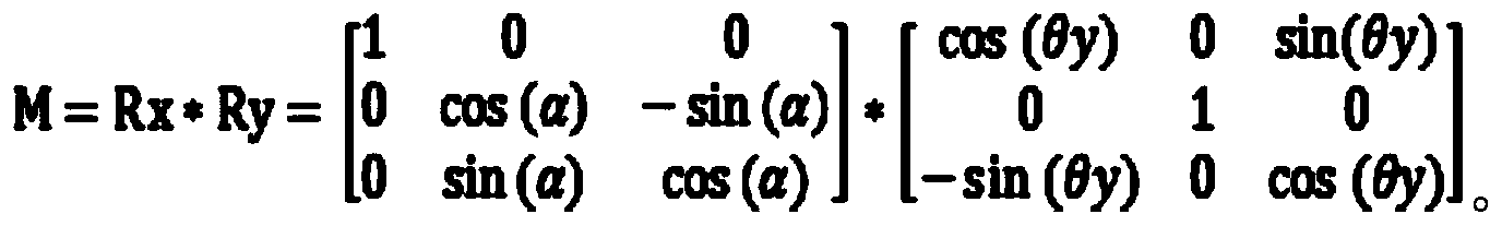
步骤S265:将所述旋转矩阵作为所述投影平面相对于所述出射平面的旋转矩阵。Step S265: Use the rotation matrix as a rotation matrix of the projection plane relative to the exit plane.
可以理解的是,可以将上述求得的投影区域所在平面的法向量与投影设备的投影光的出射平面的法向量之间的旋转矩阵作为投影区域所在平面与投影设备的投影光的出射平面之间的旋转矩阵,以便于实现对投影图像的畸变校准。It is understandable that the rotation matrix between the normal vector of the plane where the projection area is located and the normal vector of the exit plane of the projection light of the projection device obtained above can be taken as the difference between the plane where the projection area is located and the exit plane of the projection light of the projection device. Rotation matrix between in order to realize the distortion calibration of the projected image.
步骤S270:根据所述旋转矩阵对所述待校准投影图像的投影画面进行透视变换,以将所述投影画面调整为目标形状。Step S270: Perform perspective transformation on the projection image of the projection image to be calibrated according to the rotation matrix to adjust the projection image to a target shape.
通过上述旋转矩阵,可以对投影区域的投影画面的图像进行坐标变换,具体的,可以对投影画面的所有像素进行透视变换,进而实现投影设备的自动畸变校准,以将投影画面调整为一个方正的矩形,或者是其他任意形状,需要说明的是,本身实施例对投影画面的形状或者以后可能有的形状不作限定。Through the above-mentioned rotation matrix, the image of the projection screen in the projection area can be coordinate transformed. Specifically, all pixels of the projection screen can be perspective transformed to realize automatic distortion calibration of the projection device to adjust the projection screen to a square Rectangle, or other arbitrary shapes, it should be noted that the embodiment itself does not limit the shape of the projection screen or the shape that may exist in the future.
步骤S280:对所述进行透视变换后的投影画面进行双线性插值处理。Step S280: Perform bilinear interpolation processing on the projection image after perspective transformation.
作为一种方式,为了呈现投影画面更优质的显示效果,可以对畸变校准后的投影画面(即投影图像)进行双线性插值等后处理操作,以优化投影设备的投影效果。As a way, in order to present a better display effect of the projection screen, post-processing operations such as bilinear interpolation can be performed on the distortion-calibrated projection screen (ie, the projection image) to optimize the projection effect of the projection device.
本申请提供的一种投影图像校准方法,通过获取投影平面的法向量与出射平面的法向量,继而获取出射平面的法向量变换至投影平面的法向量的旋转角度,再基于旋转角度计算出射平面的法向量与投影平面的法向量之间的旋转矩阵,然后根据旋转矩阵对待校准投影图像的投影画面进行透视变换,再对进行透视变换后的投影画面进行双线性插值处理。实现了基于测距传感器所在出射平面的出射平面信息以及投影平面信息获取投影平面相对于出射平面的旋转矩阵,继而在获取了该旋转矩阵的情况下,根据旋转矩阵对待校准投影图像的投影画面进行透视变换,使得快速的完成投影图像自动校正,增强用户体验。The projection image calibration method provided by the present application obtains the normal vector of the projection plane and the normal vector of the exit plane, and then obtains the rotation angle of the normal vector of the exit plane transformed to the normal vector of the projection plane, and then calculates the exit plane based on the rotation angle According to the rotation matrix between the normal vector of and the normal vector of the projection plane, the projection screen of the projected image to be calibrated is subjected to perspective transformation according to the rotation matrix, and then bilinear interpolation is performed on the projection screen after perspective transformation. It is realized that the rotation matrix of the projection plane relative to the emission plane is obtained based on the emission plane information of the emission plane where the distance measuring sensor is located and the projection plane information. Then, when the rotation matrix is obtained, the projection screen of the projection image to be calibrated is performed according to the rotation matrix. Perspective transformation enables rapid automatic correction of projected images and enhances user experience.
请参阅图9,本申请实施例提供的一种投影图像校准装置300,运行于投影设备,所述装置300包括:Please refer to FIG. 9, a projection image calibration device 300 provided by an embodiment of the present application runs on a projection device, and the device 300 includes:
数据采集单元310,用于获取位于出射平面的三个或三个以上的测距传感 器采集的待校准投影图像的空间深度信息,所述空间深度信息为所述测距传感器构成的出射平面到投影平面的距离信息。The
数据处理单元320,用于基于所述空间深度信息以及所述测距传感器之间的相对位置关系确定投影平面信息。The
具体的,作为一种实施方式,数据处理单元320可以用于获取设置于投影设备的预设数量的测距传感器的位置坐标;基于位置坐标确定与投影设备对应的出射平面;基于出射平面以及空间深度信息获取投影平面信息。其中,需要说明的是,预设数量可以包括3个及以上,且所述预设数量的测距传感器不处于同一直线上。Specifically, as an implementation manner, the
作为一种方式,数据处理单元320,还用于基于出射平面信息以及所述投影平面信息获取所述投影平面相对于所述出射平面的旋转矩阵。As a way, the
在一种实现方式中,数据处理单元320具体可以用于基于出射平面信息以及投影平面信息获取投影平面相对于出射平面之间的旋转角度,再基于旋转角度计算投影平面相对于出射平面的旋转矩阵。In an implementation manner, the
其中,作为一种实施方式,基于旋转角度计算投影平面相对于出射平面的旋转矩阵的步骤可以包括:获取投影平面的法向量,获取出射平面的法向量;获取出射平面的法向量变换至投影平面的法向量的旋转角度;基于旋转角度计算出射平面的法向量与投影平面的法向量之间的旋转矩阵;将旋转矩阵作为投影平面相对于出射平面的旋转矩阵。Wherein, as an embodiment, the step of calculating the rotation matrix of the projection plane relative to the exit plane based on the rotation angle may include: obtaining the normal vector of the projection plane, obtaining the normal vector of the exit plane; obtaining the normal vector of the exit plane and transforming it to the projection plane The rotation angle of the normal vector of, calculate the rotation matrix between the normal vector of the exit plane and the normal vector of the projection plane based on the rotation angle; take the rotation matrix as the rotation matrix of the projection plane relative to the exit plane.
可选的,作为一种方式,上述获取出射平面的法向量变换至投影平面的法向量的旋转角度的步骤可以包括:获取出射平面的法向量在二维平面上的投影向量与对应坐标轴的正方向的夹角;将基于三维坐标轴的不同坐标轴对应的夹角作为出射平面的法向量变换至投影平面的法向量的旋转角度。Optionally, as a way, the step of obtaining the rotation angle of the normal vector of the exit plane transformed to the normal vector of the projection plane may include: obtaining the projection vector of the normal vector of the exit plane on the two-dimensional plane and the corresponding coordinate axis. The included angle in the positive direction; the included angle corresponding to the different coordinate axes based on the three-dimensional coordinate axis is used as the normal vector of the exit plane to transform the rotation angle of the normal vector of the projection plane.
投影单元330,用于根据所述旋转矩阵对所述待校准投影图像的投影画面进行透视变换,以将所述投影画面调整为目标形状。The
作为一种方式,投影单元330可以用于根据所述旋转矩阵对所述待校准投影图像的投影画面的像素进行透视变换。As a way, the
可选的,作为一种方式,装置300还可以包括后处理单元,该后处理单元用于对所述进行透视变换后的投影画面进行双线性插值处理,以便于优化投影显示效果。Optionally, as a manner, the device 300 may further include a post-processing unit configured to perform bilinear interpolation processing on the projection image after the perspective transformation, so as to optimize the projection display effect.
需要说明的是,本申请中装置实施例与前述方法实施例是相互对应的,装 置实施例中具体的原理可以参见前述方法实施例中的内容,此处不再赘述。It should be noted that the device embodiment in this application and the foregoing method embodiment correspond to each other. For specific principles in the device embodiment, please refer to the content in the foregoing method embodiment, which will not be repeated here.
下面将结合图10对本申请提供的一种投影设备进行说明。Hereinafter, a projection device provided by the present application will be described with reference to FIG. 10.
请参阅图10,基于上述的投影图像校准方法、系统、装置,本申请实施例还提供的另一种可以执行前述投影图像校准方法的投影设备100。投影设备100包括相互耦合的一个或多个(图中仅示出一个)处理器102、存储器104、数据采集模块11以及投影模块12。其中,该存储器104中存储有可以执行前述实施例中内容的程序,而处理器102可以执行该存储器104中存储的程序,存储器104包括前述实施例中所描述的装置300。Please refer to FIG. 10, based on the above-mentioned projection image calibration method, system, and device, an embodiment of the present application also provides another
其中,处理器102可以包括一个或者多个处理核。处理器102利用各种接口和线路连接整个投影设备100内的各个部分,通过运行或执行存储在存储器104内的指令、程序、代码集或指令集,以及调用存储在存储器104内的数据,执行投影设备100的各种功能和处理数据。可选地,处理器102可以采用数字信号处理(Digital Signal Processing,DSP)、现场可编程门阵列(Field-Programmable Gate Array,FPGA)、可编程逻辑阵列(Programmable Logic Array,PLA)中的至少一种硬件形式来实现。处理器102可集成中央处理器(Central Processing Unit,CPU)、视频图像处理器(Graphics Processing Unit,GPU)和调制解调器等中的一种或几种的组合。其中,CPU主要处理操作系统、用户界面和应用程序等;GPU用于负责显示内容的渲染和绘制;调制解调器用于处理无线通信。可以理解的是,上述调制解调器也可以不集成到处理器102中,单独通过一块通信芯片进行实现。The
存储器104可以包括随机存储器(Random Access Memory,RAM),也可以包括只读存储器(Read-Only Memory)。存储器104可用于存储指令、程序、代码、代码集或指令集。存储器104可包括存储程序区和存储数据区,其中,存储程序区可存储用于实现操作系统的指令、用于实现至少一个功能的指令(比如触控功能、声音播放功能、视频图像播放功能等)、用于实现上述各个方法实施例的指令等。存储数据区还可以存储投影设备100在使用中所创建的数据(例如音视频数据)等。The
所述数据采集模块11用于获取待校准投影图像的空间深度信息,可选的,空间深度信息可以包括用于显示待校准投影图像的投影区域与投影设备的距离。The
该投影模块12可以用于根据旋转矩阵对待校准投影图像的投影画面进行透 视变换,以将投影画面调整为目标形状,例如,调整为方正的矩形等。The
请参考图11,其示出了本申请实施例提供的一种计算机可读存储介质的结构框图。该计算机可读介质400中存储有程序代码,所述程序代码可被处理器调用执行上述方法实施例中所描述的方法。Please refer to FIG. 11, which shows a structural block diagram of a computer-readable storage medium provided by an embodiment of the present application. The computer-readable medium 400 stores program code, and the program code can be invoked by a processor to execute the method described in the foregoing method embodiment.
计算机可读存储介质400可以是诸如闪存、EEPROM(电可擦除可编程只读存储器)、EPROM、硬盘或者ROM之类的电子存储器。可选地,计算机可读存储介质400包括非易失性计算机可读介质(non-transitory computer-readable storage medium)。计算机可读存储介质400具有执行上述方法中的任何方法步骤的程序代码410的存储空间。这些程序代码可以从一个或者多个计算机程序产品中读出或者写入到这一个或者多个计算机程序产品中。程序代码410可以例如以适当形式进行压缩。The computer-readable storage medium 400 may be an electronic memory such as flash memory, EEPROM (Electrically Erasable Programmable Read Only Memory), EPROM, hard disk, or ROM. Optionally, the computer-readable storage medium 400 includes a non-transitory computer-readable storage medium. The computer-readable storage medium 400 has storage space for the
综上所述,本申请提供的一种投影图像校准方法、装置、投影设备以及存储介质,通过获取位于出射平面的三个或三个以上的测距传感器采集的待校准投影图像的空间深度信息,空间深度信息为测距传感器构成的出射平面到投影平面的距离信息;继而基于空间深度信息以及测距传感器之间的相对位置关系确定投影平面信息;再基于出射平面信息以及投影平面信息获取投影平面相对于出射平面的旋转矩阵;然后根据旋转矩阵对待校准投影图像的投影画面进行透视变换,以将投影画面调整为目标形状。从而通过上述方式实现了基于测距传感器所在出射平面的出射平面信息以及投影平面信息获取投影平面相对于出射平面的旋转矩阵,继而在获取了该旋转矩阵的情况下,根据旋转矩阵对待校准投影图像的投影画面进行透视变换,使得快速的完成投影图像自动校正,增强用户体验。In summary, the projection image calibration method, device, projection equipment, and storage medium provided by the present application acquire the spatial depth information of the projection image to be calibrated collected by three or more range-finding sensors located on the exit plane , The spatial depth information is the distance information from the exit plane to the projection plane formed by the ranging sensor; then the projection plane information is determined based on the spatial depth information and the relative position relationship between the ranging sensors; and then the projection is obtained based on the exit plane information and the projection plane information The rotation matrix of the plane relative to the exit plane; then, according to the rotation matrix, a perspective transformation is performed on the projection image of the projection image to be calibrated to adjust the projection image to the target shape. In this way, the rotation matrix of the projection plane relative to the projection plane is obtained based on the exit plane information and the projection plane information of the exit plane where the ranging sensor is located, and then when the rotation matrix is acquired, the projection image is to be calibrated according to the rotation matrix. The projection image of the camera is transformed into perspective, so that the automatic correction of the projected image can be completed quickly and the user experience is enhanced.
最后应说明的是:以上实施例仅用以说明本申请的技术方案,而非对其限制;尽管参照前述实施例对本申请进行了详细的说明,本领域的普通技术人员当理解:其依然可以对前述各实施例所记载的技术方案进行修改,或者对其中部分技术特征进行等同替换;而这些修改或者替换,并不驱使相应技术方案的本质脱离本申请各实施例技术方案的精神和范围。Finally, it should be noted that the above embodiments are only used to illustrate the technical solutions of the application, not to limit them; although the application has been described in detail with reference to the foregoing embodiments, those of ordinary skill in the art should understand that: The technical solutions recorded in the foregoing embodiments are modified, or some of the technical features are equivalently replaced; these modifications or replacements do not drive the essence of the corresponding technical solutions to deviate from the spirit and scope of the technical solutions of the embodiments of the present application.
Claims (11)
Applications Claiming Priority (2)
| Application Number | Priority Date | Filing Date | Title |
|---|---|---|---|
| CN201910763891.9A CN112399158B (en) | 2019-08-19 | 2019-08-19 | Projection image calibration method, device and projection equipment |
| CN201910763891.9 | 2019-08-19 |
Publications (1)
| Publication Number | Publication Date |
|---|---|
| WO2021031781A1 true WO2021031781A1 (en) | 2021-02-25 |
Family
ID=74603328
Family Applications (1)
| Application Number | Title | Priority Date | Filing Date |
|---|---|---|---|
| PCT/CN2020/103587 Ceased WO2021031781A1 (en) | 2019-08-19 | 2020-07-22 | Method and device for calibrating projection image and projection device |
Country Status (2)
| Country | Link |
|---|---|
| CN (1) | CN112399158B (en) |
| WO (1) | WO2021031781A1 (en) |
Cited By (18)
| Publication number | Priority date | Publication date | Assignee | Title |
|---|---|---|---|---|
| CN114067016A (en) * | 2021-11-16 | 2022-02-18 | 南京佗道医疗科技有限公司 | Inclination calibration method for projected image |
| CN114190957A (en) * | 2021-12-31 | 2022-03-18 | 东软医疗系统股份有限公司 | Auxiliary positioning method and device, storage medium and computer equipment |
| CN114222102A (en) * | 2022-02-08 | 2022-03-22 | 峰米(重庆)创新科技有限公司 | Projection equipment and adjusting method, control device and readable storage medium thereof |
| CN114545377A (en) * | 2022-03-03 | 2022-05-27 | 北京亮道智能汽车技术有限公司 | A laser radar calibration method and device |
| CN114640833A (en) * | 2022-03-11 | 2022-06-17 | 峰米(重庆)创新科技有限公司 | Projection picture adjusting method and device, electronic equipment and storage medium |
| CN115311133A (en) * | 2022-08-09 | 2022-11-08 | 北京淳中科技股份有限公司 | Image processing method and device, electronic equipment and storage medium |
| CN115733962A (en) * | 2021-08-30 | 2023-03-03 | 安克创新科技股份有限公司 | Projection picture correction method and device, and projector |
| CN115767045A (en) * | 2021-09-02 | 2023-03-07 | 成都极米科技股份有限公司 | Projector, projection control method and device |
| CN116188556A (en) * | 2022-12-08 | 2023-05-30 | 深圳市华汉伟业科技有限公司 | Three-dimensional measurement method of specular object, computer-readable storage medium |
| CN116208750A (en) * | 2021-12-01 | 2023-06-02 | 成都极米科技股份有限公司 | Obstacle avoidance testing system, method, device, equipment and computer readable storage medium |
| CN116418958A (en) * | 2021-12-31 | 2023-07-11 | 深圳光峰科技股份有限公司 | Projection calibration method, device, electronic equipment and storage medium |
| CN116684561A (en) * | 2023-08-03 | 2023-09-01 | 深圳新智联软件有限公司 | Startup image adjusting method and device, electronic equipment and storage medium |
| CN116755285A (en) * | 2023-06-20 | 2023-09-15 | 联想新视界(南昌)人工智能工研院有限公司 | Laser ranging intelligent projection adjustment system and method based on embedded and 3D models |
| CN116939177A (en) * | 2022-04-12 | 2023-10-24 | 深圳光峰科技股份有限公司 | Projection correction method of projection equipment, projection equipment and storage medium |
| CN117278735A (en) * | 2023-09-15 | 2023-12-22 | 山东锦霖智能科技集团有限公司 | An immersive image projection device |
| CN117910279A (en) * | 2024-03-18 | 2024-04-19 | 西北工业大学 | Three-dimensional sound field rapid processing method based on space coordinate rotation transformation |
| CN118413639A (en) * | 2024-05-16 | 2024-07-30 | 深圳市强普光电有限公司 | A projector image positioning method, device, equipment and storage medium |
| CN119110051A (en) * | 2023-06-07 | 2024-12-10 | 珠海莫界科技有限公司 | Three-dimensional display method, device, electronic device and storage medium |
Families Citing this family (8)
| Publication number | Priority date | Publication date | Assignee | Title |
|---|---|---|---|---|
| CN114827557B (en) * | 2021-03-05 | 2023-05-02 | 成都极米科技股份有限公司 | Projection trapezoid correction method, projection trapezoid correction device and projection system |
| CN112804507B (en) * | 2021-03-19 | 2021-08-31 | 深圳市火乐科技发展有限公司 | Projector correction method, projector correction system, storage medium, and electronic device |
| CN114812382B (en) * | 2021-04-14 | 2023-11-28 | 成都极米科技股份有限公司 | Multi-point measuring method and device for projection surface, storage medium and projection equipment |
| CN116489319A (en) * | 2022-01-17 | 2023-07-25 | 深圳光峰科技股份有限公司 | Projection correction method and projection system |
| CN116489320A (en) * | 2022-01-17 | 2023-07-25 | 深圳光峰科技股份有限公司 | Projection correction method and TOF projection system |
| CN114936978B (en) * | 2022-05-31 | 2025-08-22 | 上海炬佑智能科技有限公司 | Method for obtaining projection correction amount, projection system and projection correction method |
| CN116582658B (en) * | 2023-05-30 | 2026-04-03 | 深圳市火乐科技发展有限公司 | Parameter determination methods, image correction, apparatus, media, and projection equipment |
| CN120321374A (en) * | 2024-01-08 | 2025-07-15 | 广州视源电子科技股份有限公司 | Relative posture detection method and related device between projection plane and projection device |
Citations (11)
| Publication number | Priority date | Publication date | Assignee | Title |
|---|---|---|---|---|
| US20050024598A1 (en) * | 2003-07-30 | 2005-02-03 | Casio Computer Co., Ltd. | Projector and method of projecting projection image |
| CN101872108A (en) * | 2010-05-25 | 2010-10-27 | 中兴通讯股份有限公司 | Projector, method for adjusting display screen thereof, and mobile terminal |
| JP2013005140A (en) * | 2011-06-15 | 2013-01-07 | Dainippon Printing Co Ltd | Image processing apparatus and image processing method |
| CN104349095A (en) * | 2013-08-09 | 2015-02-11 | 联想(北京)有限公司 | Image regulating method, image regulating device and electronic equipment |
| CN105227881A (en) * | 2015-09-15 | 2016-01-06 | 海信集团有限公司 | A kind of projected picture correcting method and projector equipment |
| CN106200225A (en) * | 2016-09-21 | 2016-12-07 | 北京小米移动软件有限公司 | The trapezoidal distortion correction method of projector and device |
| CN106937101A (en) * | 2017-03-22 | 2017-07-07 | 成都市极米科技有限公司 | View field's bearing calibration and system |
| CN107454372A (en) * | 2016-06-01 | 2017-12-08 | 中兴通讯股份有限公司 | Method for correcting image, device and projecting apparatus |
| CN107707898A (en) * | 2017-09-30 | 2018-02-16 | 歌尔科技有限公司 | The image distortion correcting method and laser-projector of laser-projector |
| CN107835400A (en) * | 2017-11-13 | 2018-03-23 | 四川长虹电器股份有限公司 | Realize the method and device that projected image corrects automatically |
| CN108289208A (en) * | 2018-01-24 | 2018-07-17 | 歌尔股份有限公司 | A kind of projected picture auto-correction method and device |
Family Cites Families (4)
| Publication number | Priority date | Publication date | Assignee | Title |
|---|---|---|---|---|
| TW529728U (en) * | 2001-12-14 | 2003-04-21 | Mitac Technology Corp | Inspection and testing apparatus for image correction of projection equipment |
| CN102148949A (en) * | 2011-05-03 | 2011-08-10 | 苏州佳世达光电有限公司 | Projector image correction method, system and projector |
| CN104657103B (en) * | 2015-03-16 | 2017-06-16 | 哈尔滨工业大学 | Hand-held CAVE optical projection systems based on depth camera |
| CN106612422B (en) * | 2015-12-31 | 2018-08-28 | 北京一数科技有限公司 | A kind of projection correction's method and device |
-
2019
- 2019-08-19 CN CN201910763891.9A patent/CN112399158B/en active Active
-
2020
- 2020-07-22 WO PCT/CN2020/103587 patent/WO2021031781A1/en not_active Ceased
Patent Citations (11)
| Publication number | Priority date | Publication date | Assignee | Title |
|---|---|---|---|---|
| US20050024598A1 (en) * | 2003-07-30 | 2005-02-03 | Casio Computer Co., Ltd. | Projector and method of projecting projection image |
| CN101872108A (en) * | 2010-05-25 | 2010-10-27 | 中兴通讯股份有限公司 | Projector, method for adjusting display screen thereof, and mobile terminal |
| JP2013005140A (en) * | 2011-06-15 | 2013-01-07 | Dainippon Printing Co Ltd | Image processing apparatus and image processing method |
| CN104349095A (en) * | 2013-08-09 | 2015-02-11 | 联想(北京)有限公司 | Image regulating method, image regulating device and electronic equipment |
| CN105227881A (en) * | 2015-09-15 | 2016-01-06 | 海信集团有限公司 | A kind of projected picture correcting method and projector equipment |
| CN107454372A (en) * | 2016-06-01 | 2017-12-08 | 中兴通讯股份有限公司 | Method for correcting image, device and projecting apparatus |
| CN106200225A (en) * | 2016-09-21 | 2016-12-07 | 北京小米移动软件有限公司 | The trapezoidal distortion correction method of projector and device |
| CN106937101A (en) * | 2017-03-22 | 2017-07-07 | 成都市极米科技有限公司 | View field's bearing calibration and system |
| CN107707898A (en) * | 2017-09-30 | 2018-02-16 | 歌尔科技有限公司 | The image distortion correcting method and laser-projector of laser-projector |
| CN107835400A (en) * | 2017-11-13 | 2018-03-23 | 四川长虹电器股份有限公司 | Realize the method and device that projected image corrects automatically |
| CN108289208A (en) * | 2018-01-24 | 2018-07-17 | 歌尔股份有限公司 | A kind of projected picture auto-correction method and device |
Cited By (21)
| Publication number | Priority date | Publication date | Assignee | Title |
|---|---|---|---|---|
| CN115733962A (en) * | 2021-08-30 | 2023-03-03 | 安克创新科技股份有限公司 | Projection picture correction method and device, and projector |
| CN115767045A (en) * | 2021-09-02 | 2023-03-07 | 成都极米科技股份有限公司 | Projector, projection control method and device |
| CN114067016A (en) * | 2021-11-16 | 2022-02-18 | 南京佗道医疗科技有限公司 | Inclination calibration method for projected image |
| CN116208750A (en) * | 2021-12-01 | 2023-06-02 | 成都极米科技股份有限公司 | Obstacle avoidance testing system, method, device, equipment and computer readable storage medium |
| CN116418958A (en) * | 2021-12-31 | 2023-07-11 | 深圳光峰科技股份有限公司 | Projection calibration method, device, electronic equipment and storage medium |
| CN114190957A (en) * | 2021-12-31 | 2022-03-18 | 东软医疗系统股份有限公司 | Auxiliary positioning method and device, storage medium and computer equipment |
| CN114222102A (en) * | 2022-02-08 | 2022-03-22 | 峰米(重庆)创新科技有限公司 | Projection equipment and adjusting method, control device and readable storage medium thereof |
| CN114545377A (en) * | 2022-03-03 | 2022-05-27 | 北京亮道智能汽车技术有限公司 | A laser radar calibration method and device |
| CN114640833A (en) * | 2022-03-11 | 2022-06-17 | 峰米(重庆)创新科技有限公司 | Projection picture adjusting method and device, electronic equipment and storage medium |
| CN116939177A (en) * | 2022-04-12 | 2023-10-24 | 深圳光峰科技股份有限公司 | Projection correction method of projection equipment, projection equipment and storage medium |
| CN115311133A (en) * | 2022-08-09 | 2022-11-08 | 北京淳中科技股份有限公司 | Image processing method and device, electronic equipment and storage medium |
| CN116188556A (en) * | 2022-12-08 | 2023-05-30 | 深圳市华汉伟业科技有限公司 | Three-dimensional measurement method of specular object, computer-readable storage medium |
| CN119110051A (en) * | 2023-06-07 | 2024-12-10 | 珠海莫界科技有限公司 | Three-dimensional display method, device, electronic device and storage medium |
| CN116755285A (en) * | 2023-06-20 | 2023-09-15 | 联想新视界(南昌)人工智能工研院有限公司 | Laser ranging intelligent projection adjustment system and method based on embedded and 3D models |
| CN116684561A (en) * | 2023-08-03 | 2023-09-01 | 深圳新智联软件有限公司 | Startup image adjusting method and device, electronic equipment and storage medium |
| CN116684561B (en) * | 2023-08-03 | 2023-11-24 | 深圳新智联软件有限公司 | Startup image adjusting method and device, electronic equipment and storage medium |
| CN117278735A (en) * | 2023-09-15 | 2023-12-22 | 山东锦霖智能科技集团有限公司 | An immersive image projection device |
| CN117278735B (en) * | 2023-09-15 | 2024-05-17 | 山东锦霖智能科技集团有限公司 | Immersive image projection equipment |
| CN117910279A (en) * | 2024-03-18 | 2024-04-19 | 西北工业大学 | Three-dimensional sound field rapid processing method based on space coordinate rotation transformation |
| CN117910279B (en) * | 2024-03-18 | 2024-05-28 | 西北工业大学 | Three-dimensional sound field rapid processing method based on space coordinate rotation transformation |
| CN118413639A (en) * | 2024-05-16 | 2024-07-30 | 深圳市强普光电有限公司 | A projector image positioning method, device, equipment and storage medium |
Also Published As
| Publication number | Publication date |
|---|---|
| CN112399158B (en) | 2023-06-30 |
| CN112399158A (en) | 2021-02-23 |
Similar Documents
| Publication | Publication Date | Title |
|---|---|---|
| WO2021031781A1 (en) | Method and device for calibrating projection image and projection device | |
| CN112689135B (en) | Projection correction method, projection correction device, storage medium and electronic equipment | |
| US9866818B2 (en) | Image processing apparatus and method, image processing system and program | |
| CN114727081B (en) | Projector projection correction method and device and projector | |
| CN110381302B (en) | Projection pattern correction method, device and system for projection system | |
| CN113643414A (en) | Three-dimensional image generation method and device, electronic equipment and storage medium | |
| CN116418958B (en) | Projection calibration method, device, electronic device and storage medium | |
| CN110136207B (en) | Fisheye camera calibration system, fisheye camera calibration method, fisheye camera calibration device, electronic equipment and storage medium | |
| KR20220162595A (en) | Electronic apparatus and control method thereof | |
| CN115174879B (en) | Projection picture correction method, device, computer equipment and storage medium | |
| CN115278184B (en) | Projection picture correction method and device | |
| US20180108173A1 (en) | Method for improving occluded edge quality in augmented reality based on depth camera | |
| CN110691228A (en) | Three-dimensional transformation-based depth image noise marking method and device and storage medium | |
| CN112017133B (en) | Image display method and device and electronic equipment | |
| US12342108B2 (en) | Electronic apparatus and method for controlling thereof | |
| TWI662694B (en) | 3d image capture method and system | |
| WO2019155903A1 (en) | Information processing device and method | |
| CN114820756A (en) | Depth map processing method and device, electronic device and readable storage medium | |
| TWI892360B (en) | Projection image correction method, device, projection equipment, acquisition equipment and readable storage medium | |
| JP2008211356A (en) | Projector, program, and information storage medium | |
| CN112181230A (en) | Data display method and device and electronic equipment | |
| CN114723800B (en) | Point cloud data correction method and correction device, electronic device and storage medium | |
| CN113674356B (en) | Camera screening method and related device | |
| CN116939177A (en) | Projection correction method of projection equipment, projection equipment and storage medium | |
| CN111353945A (en) | Fisheye image correction method, fisheye image correction device and storage medium |
Legal Events
| Date | Code | Title | Description |
|---|---|---|---|
| 121 | Ep: the epo has been informed by wipo that ep was designated in this application |
Ref document number: 20855640 Country of ref document: EP Kind code of ref document: A1 |
|
| NENP | Non-entry into the national phase |
Ref country code: DE |
|
| 122 | Ep: pct application non-entry in european phase |
Ref document number: 20855640 Country of ref document: EP Kind code of ref document: A1 |