WO2020050263A1 - Coated tool and cutting tool - Google Patents
Coated tool and cutting tool Download PDFInfo
- Publication number
- WO2020050263A1 WO2020050263A1 PCT/JP2019/034599 JP2019034599W WO2020050263A1 WO 2020050263 A1 WO2020050263 A1 WO 2020050263A1 JP 2019034599 W JP2019034599 W JP 2019034599W WO 2020050263 A1 WO2020050263 A1 WO 2020050263A1
- Authority
- WO
- WIPO (PCT)
- Prior art keywords
- layer
- holes
- average value
- coated tool
- boundary
- Prior art date
- Legal status (The legal status is an assumption and is not a legal conclusion. Google has not performed a legal analysis and makes no representation as to the accuracy of the status listed.)
- Ceased
Links
Images
Classifications
-
- B—PERFORMING OPERATIONS; TRANSPORTING
- B23—MACHINE TOOLS; METAL-WORKING NOT OTHERWISE PROVIDED FOR
- B23B—TURNING; BORING
- B23B27/00—Tools for turning or boring machines; Tools of a similar kind in general; Accessories therefor
- B23B27/14—Cutting tools of which the bits or tips or cutting inserts are of special material
- B23B27/16—Cutting tools of which the bits or tips or cutting inserts are of special material with exchangeable cutting bits or cutting inserts, e.g. able to be clamped
-
- C—CHEMISTRY; METALLURGY
- C23—COATING METALLIC MATERIAL; COATING MATERIAL WITH METALLIC MATERIAL; CHEMICAL SURFACE TREATMENT; DIFFUSION TREATMENT OF METALLIC MATERIAL; COATING BY VACUUM EVAPORATION, BY SPUTTERING, BY ION IMPLANTATION OR BY CHEMICAL VAPOUR DEPOSITION, IN GENERAL; INHIBITING CORROSION OF METALLIC MATERIAL OR INCRUSTATION IN GENERAL
- C23C—COATING METALLIC MATERIAL; COATING MATERIAL WITH METALLIC MATERIAL; SURFACE TREATMENT OF METALLIC MATERIAL BY DIFFUSION INTO THE SURFACE, BY CHEMICAL CONVERSION OR SUBSTITUTION; COATING BY VACUUM EVAPORATION, BY SPUTTERING, BY ION IMPLANTATION OR BY CHEMICAL VAPOUR DEPOSITION, IN GENERAL
- C23C16/00—Chemical coating by decomposition of gaseous compounds, without leaving reaction products of surface material in the coating, i.e. chemical vapour deposition [CVD] processes
- C23C16/22—Chemical coating by decomposition of gaseous compounds, without leaving reaction products of surface material in the coating, i.e. chemical vapour deposition [CVD] processes characterised by the deposition of inorganic material, other than metallic material
- C23C16/30—Deposition of compounds, mixtures or solid solutions, e.g. borides, carbides, nitrides
- C23C16/40—Oxides
- C23C16/403—Oxides of aluminium, magnesium or beryllium
-
- B—PERFORMING OPERATIONS; TRANSPORTING
- B23—MACHINE TOOLS; METAL-WORKING NOT OTHERWISE PROVIDED FOR
- B23C—MILLING
- B23C5/00—Milling-cutters
- B23C5/16—Milling-cutters characterised by physical features other than shape
-
- C—CHEMISTRY; METALLURGY
- C23—COATING METALLIC MATERIAL; COATING MATERIAL WITH METALLIC MATERIAL; CHEMICAL SURFACE TREATMENT; DIFFUSION TREATMENT OF METALLIC MATERIAL; COATING BY VACUUM EVAPORATION, BY SPUTTERING, BY ION IMPLANTATION OR BY CHEMICAL VAPOUR DEPOSITION, IN GENERAL; INHIBITING CORROSION OF METALLIC MATERIAL OR INCRUSTATION IN GENERAL
- C23C—COATING METALLIC MATERIAL; COATING MATERIAL WITH METALLIC MATERIAL; SURFACE TREATMENT OF METALLIC MATERIAL BY DIFFUSION INTO THE SURFACE, BY CHEMICAL CONVERSION OR SUBSTITUTION; COATING BY VACUUM EVAPORATION, BY SPUTTERING, BY ION IMPLANTATION OR BY CHEMICAL VAPOUR DEPOSITION, IN GENERAL
- C23C16/00—Chemical coating by decomposition of gaseous compounds, without leaving reaction products of surface material in the coating, i.e. chemical vapour deposition [CVD] processes
- C23C16/22—Chemical coating by decomposition of gaseous compounds, without leaving reaction products of surface material in the coating, i.e. chemical vapour deposition [CVD] processes characterised by the deposition of inorganic material, other than metallic material
- C23C16/30—Deposition of compounds, mixtures or solid solutions, e.g. borides, carbides, nitrides
- C23C16/34—Nitrides
-
- C—CHEMISTRY; METALLURGY
- C23—COATING METALLIC MATERIAL; COATING MATERIAL WITH METALLIC MATERIAL; CHEMICAL SURFACE TREATMENT; DIFFUSION TREATMENT OF METALLIC MATERIAL; COATING BY VACUUM EVAPORATION, BY SPUTTERING, BY ION IMPLANTATION OR BY CHEMICAL VAPOUR DEPOSITION, IN GENERAL; INHIBITING CORROSION OF METALLIC MATERIAL OR INCRUSTATION IN GENERAL
- C23C—COATING METALLIC MATERIAL; COATING MATERIAL WITH METALLIC MATERIAL; SURFACE TREATMENT OF METALLIC MATERIAL BY DIFFUSION INTO THE SURFACE, BY CHEMICAL CONVERSION OR SUBSTITUTION; COATING BY VACUUM EVAPORATION, BY SPUTTERING, BY ION IMPLANTATION OR BY CHEMICAL VAPOUR DEPOSITION, IN GENERAL
- C23C16/00—Chemical coating by decomposition of gaseous compounds, without leaving reaction products of surface material in the coating, i.e. chemical vapour deposition [CVD] processes
- C23C16/22—Chemical coating by decomposition of gaseous compounds, without leaving reaction products of surface material in the coating, i.e. chemical vapour deposition [CVD] processes characterised by the deposition of inorganic material, other than metallic material
- C23C16/30—Deposition of compounds, mixtures or solid solutions, e.g. borides, carbides, nitrides
- C23C16/36—Carbonitrides
-
- B—PERFORMING OPERATIONS; TRANSPORTING
- B23—MACHINE TOOLS; METAL-WORKING NOT OTHERWISE PROVIDED FOR
- B23B—TURNING; BORING
- B23B2222/00—Materials of tools or workpieces composed of metals, alloys or metal matrices
- B23B2222/04—Aluminium
-
- B—PERFORMING OPERATIONS; TRANSPORTING
- B23—MACHINE TOOLS; METAL-WORKING NOT OTHERWISE PROVIDED FOR
- B23B—TURNING; BORING
- B23B2222/00—Materials of tools or workpieces composed of metals, alloys or metal matrices
- B23B2222/88—Titanium
Definitions
- the present disclosure relates to a coated tool used for cutting.
- a coated tool described in Patent Document 1 contains a layer containing a titanium (Ti) compound (titanium compound layer) and aluminum oxide (Al 2 O 3 ) on the surface of a base made of a cemented carbide or the like. It has a configuration in which a coating layer including a layer (aluminum oxide layer) is formed.
- Ti titanium
- Al 2 O 3 aluminum oxide
- Patent Document 1 describes that the titanium compound layer has excellent high-temperature strength by being oriented to the (112) plane.
- Patent Document 2 a plurality of holes are formed at the interface between the titanium compound layer and the aluminum oxide layer. It is described that an impact mitigation effect can be obtained by the plurality of holes.
- a coated tool of the present disclosure includes a substrate having a first surface, and a coating layer located on at least the first surface of the substrate.
- the coating layer includes a first layer containing a titanium compound, which is located on the first surface, and a second layer containing aluminum oxide, which is located on and in contact with the first layer.
- the first layer has a plurality of holes located in a cross section orthogonal to the first surface and arranged in a direction along a boundary between the first layer and the second layer.
- the average value of the width of the holes in the direction along the interface is smaller than the average value of the interval between the adjacent holes.
- a cutting tool according to the present disclosure has a rod shape extending from a first end toward a second end, and has a holder having a pocket located on the first end side, and a coating tool located in the pocket.
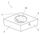
- FIG. 1 is a perspective view illustrating a coating tool according to the present disclosure.
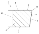
- FIG. 2 is a cross-sectional view taken along the line AA of the coated tool shown in FIG. 1.
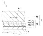
- FIG. 3 is an enlarged view near a coating layer in the coating tool shown in FIG. 2.
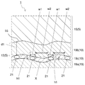
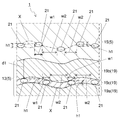
- FIG. 4 is an enlarged view illustrating an example of a region B1 illustrated in FIG. 3.
- FIG. 4 is an enlarged view illustrating another example of a region B1 illustrated in FIG. 3. It is a top view showing the cutting tool of this indication.
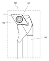
- FIG. 7 is an enlarged view of a region B2 shown in FIG. 6.
- the coated tool of the present disclosure will be described in detail with reference to the drawings.
- the coating tool may include any components not shown in the referenced figures.
- the dimensions of the members in the drawings do not faithfully represent the actual dimensions of the constituent members, the dimensional ratios of the respective members, and the like.
- a coating tool 1 includes a base 3 and a coating layer 5.
- the base 3 includes a first surface 7 (an upper surface in FIG. 2), a second surface 9 (a side surface in FIG. 2) adjacent to the first surface 7, and at least one ridge line where the first surface 7 and the second surface 9 intersect. And a cutting blade 11 located in the portion.
- the base 3 in the example shown in FIG. 1 has a square plate shape, and the first surface 7 is square. Therefore, the number of the second surfaces 9 is four. At least a part of the first face 7 is a so-called rake face area, and at least a part of the second face 9 is a so-called flank face area.
- the shape of the base 3 is not limited to a square plate shape.
- the first surface 7 may be a triangle, a pentagon, a hexagon, or a circle.
- the base 3 is not limited to a plate shape, and may be, for example, a column shape.
- the coating layer 5 is located on at least the first surface 7 of the base 3.
- the coating layer 5 may be located only on the first surface 7, or may be located on another surface of the base 3 other than the first surface 7.
- the coating layer 5 is located on the second surface 9 in addition to the first surface 7.
- the coating layer 5 is provided to improve characteristics such as wear resistance and chipping resistance of the coated tool 1 in cutting.
- the coating layer 5 has a first layer 13 and a second layer 15.
- the first layer 13 is located on the first surface 7 and contains a titanium compound.
- the second layer 15 is located in contact with the first layer 13 and contains aluminum oxide (Al 2 O 3 ).
- the titanium compound contained in the first layer 13 examples include titanium carbide, nitride, oxide, carbonitride, carbonate, and carbonitride.
- the first layer 13 may have a configuration containing only one of the above compounds, or may have a configuration containing a plurality of the above compounds.
- the first layer 13 may have a single-layer configuration or a configuration in which a plurality of layers are stacked as long as the first layer 13 contains a titanium compound.
- the first layer 13 may have a configuration in which a titanium nitride layer 17 and a titanium carbonitride layer 19 are stacked.
- the titanium nitride layer 17 and the titanium carbonitride layer 19 are mainly composed of titanium nitride and titanium carbonitride, respectively, and may contain other components.
- the “main component” means that the component has the largest value of mass% as compared with other components.
- the coating layer 5 may be constituted by only the first layer 13 and the second layer 15, or may have a layer other than these layers.
- another layer may be present between the base 3 and the first layer 13, or another layer may be present on the second layer 15.
- the titanium carbonitride layer 19 may have a configuration in which a plurality of regions having different compositions are stacked.
- the titanium carbonitride layer 19 may have a structure in which a so-called MT (Moderate Temperature) -first region 19a and a so-called HT (High Temperature) -second region 19b are stacked.
- MT Mode Temperature
- HT High Temperature
- the first layer 13 may further have an intermediate region 19c between the first region 19a and the second region 19b.
- the boundaries between the layers and the regions are specified by observing, for example, an electron microscope photograph (a scanning electron microscope (SEM) photograph or a transmission electron microscope (TEM: Transmission Electron Microscope) photograph). It is possible. The specification can be made based on the ratio of elements constituting each layer, and the difference in crystal size and orientation.
- Examples of the aluminum oxide contained in the second layer 15 include ⁇ -alumina ( ⁇ -Al 2 O 3 ), ⁇ -alumina ( ⁇ -Al 2 O 3 ), and ⁇ -alumina ( ⁇ -Al 2 O 3 ). O 3 ).
- the second layer 15 contains ⁇ -alumina, the heat resistance of the coated tool 1 can be improved.
- the second layer 15 may have a configuration containing only one of the above compounds, or may have a configuration containing a plurality of the above compounds.
- Which of the above compounds the aluminum oxide contained in the second layer 15 can be evaluated, for example, by performing X-ray diffraction (XRD: X-Ray @ Diffraction) analysis and observing the distribution of peak values. .
- XRD X-ray diffraction
- the content ratio of the titanium compound in the first layer 13 and the content ratio of aluminum oxide in the second layer 15 are not limited to specific values.
- the first layer 13 contains a titanium compound as a main component
- the second layer 15 contains aluminum oxide as a main component.
- the “main component” means a component having the largest value of mass% as compared with other components.
- the first layer 13 may contain components other than the titanium compound, and the second layer 15 may contain components other than aluminum oxide.
- the bondability between the first layer 13 and the second layer 15 is improved.
- the first layer 13 has a measured tilt angle within a tilt angle range of 0 to 10 ° when the tilt angle formed by the crystal plane of the crystal grain with respect to the surface normal is measured.
- the inclination angle number distribution graph in which the highest peak appears and the total ratio of the frequencies existing in the inclination angle section of 0 to 10 ° is 45% or more of the entire frequency in the inclination angle number distribution graph is configured. This can increase the high-temperature strength.
- ⁇ The above-described measurement of the inclination angle can be evaluated by, for example, measurement using an EBSD (Electron Backscatter Diffraction) method.
- EBSD Electro Backscatter Diffraction
- An example of measurement using the backscattered electron diffraction method will be described below.
- the polished surface which is the surface of the first layer exposed in this manner, is irradiated with an electron beam, and the tilt angle formed by the normal of the ⁇ 112 ⁇ plane at intervals of 0.1 ⁇ m in a range of about 40 ⁇ 25 ⁇ m 2 is measured. I do.
- the measured tilt angles within the range of 0 to 45 ° among the measured tilt angles may be classified at a pitch of 0.25 degrees.
- the coating layer 5 of the present disclosure has holes 21 inside the first phase 13 as shown in FIG. Specifically, the coating layer 5 is located on the first layer 13 in a section along a boundary 16 between the first layer 13 and the second layer 15 in a cross section orthogonal to the first surface 7 of the base 3. It has a plurality of holes 21.
- the average value of the width w1 of the holes 21 in the direction parallel to the first surface 7 is equal to the distance between the adjacent holes 21, that is, the width w2 of the first portion X. Less than the average value.
- the coated tool 1 having such a configuration can obtain high impact resistance in the holes 21 while suppressing a decrease in the strength of the first portion X.
- the evaluation may be made based on the average value of the width w1 of about ten holes 21 arranged side by side in the cross section. For example, a 10 ⁇ m square region including the boundary between the first layer 13 and the second layer 15 may be extracted from a cross section orthogonal to the first surface 7 and the width w1 of the holes 21 in this region may be measured. Further, the average value of the width w2 of the first portion X may be evaluated by the average value of the intervals between about five holes 21 arranged side by side in the cross section.
- the holes 21 only have to exist in the first layer 13.
- the configuration may be located in each of the layer 13 and the second layer 15.
- a virtual line segment along the boundary between the first layer 13 and the second layer 15 is indicated by a dashed line, and a hole 21 located in the second layer 15 is formed by the first layer 13 and the second layer 15. Is located along the border of.
- the hole 21 is located along the boundary between the first layer 13 and the second layer 15 means that the interval between the plurality of holes 21 up to the boundary between the first layer 13 and the second layer 15 is the same. This means that the average value is within a range of ⁇ 20%.
- the first layer 13 contains titanium carbonitride as a titanium compound and the second layer 15 contains ⁇ -alumina as aluminum oxide from the viewpoint of heat resistance and durability of the coated tool 1, a plurality of When the holes 21 are located in the first layer 13, the durability of the coated tool 1 is further enhanced.
- titanium carbonitride has a higher hardness but a lower impact resistance than ⁇ -alumina. Therefore, when the holes 21 are located in the first layer 13, 21 can improve the impact resistance, and the durability of the coated tool 1 can be further increased.
- the size of the holes 21 is not particularly limited, but can be set, for example, to 20 to 200 nm. When the size of the holes 21 is 20 nm or more, the effect of the holes 21 to reduce the impact can be enhanced. When the size of the holes 21 is 200 nm or less, the strength of the first layer 13 is easily maintained. Note that the size of the hole 21 in the present embodiment means the maximum value of the width w1 in a cross section of the hole 21 perpendicular to the first surface 7.
- the shape of the holes 21 is not particularly limited, but in a cross section orthogonal to the first surface 7, a direction parallel to the first surface 7 than a height h 1 in a direction orthogonal to the first surface 7. Is large, in other words, the average value of the width w1 of the holes 21 in the direction parallel to the first surface 7 is the average of the heights h1 of the holes 21 in the direction orthogonal to the first surface 7.
- the value is larger than the value, the impact resistance can be further increased while the ratio of the holes 21 is suppressed. This is for the following reason.
- the ratio of the average value of the width w1 of the holes 21 in the direction orthogonal to the first surface 7 to the average value of the height h1 of the holes 21 in the direction parallel to the first surface 7 is 1. If it is 2 or more, the cutting load can be easily absorbed in a wide range of the holes 21. When the above ratio is 2 or less, the amount of deformation of the holes 21 in the direction orthogonal to the first surface 7 is easily secured, so that the holes 21 can stably absorb the cutting load.
- the maximum height of the boundary between the first surface 7 and the second surface 9 in a cross section orthogonal to the first surface 7 is Rz
- the height h1 of the hole 21 in the direction orthogonal to the first surface 7 When the average value is smaller than Rz, it is easy to suppress a decrease in the durability of the coating layer 5.
- the coated tool 1 of the present disclosure has high impact resistance due to the deformation of the first portion X and the plurality of holes 21 located between the adjacent holes 21 in the first layer 13.
- the average value of the width of the holes 21 in the direction orthogonal to the first surface 7 is smaller than Rz, the imaginary line connecting the adjacent holes 21 bends more greatly than the width of the holes 21. It is shown in a zigzag shape.
- the distance from the hole 21 to the boundary between the first layer 13 and the second layer 15 can be sufficiently secured as compared with the first portion X. This is because even if a crack occurs in the first layer 13, the crack does not easily reach the boundary between the first layer 13 and the second layer 15. Since the above-mentioned cracks do not easily reach the boundary between the first layer 13 and the second layer 15, the bondability between the first layer 13 and the second layer 15 does not easily decrease.
- the holes 21 are located in the first layer 13 and are located away from the boundary between the first layer 13 and the second layer 15.
- the average value of the distance d 1 from the hole 21 to the boundary between the first layer 13 and the second layer 15 is equal to the hole 21 in the direction orthogonal to the first surface 7. Is larger than the average value of the height h1, the joining property between the first layer 13 and the second layer 15 is hardly reduced while the impact resistance of the coating layer 5 is increased.
- the distance from the hole 21 to the boundary between the first layer 13 and the second layer 15 can be sufficiently secured as compared with the size of the hole 21, and the hole 21 is deformed to absorb the cutting load. This is because the boundary between the first layer 13 and the second layer 15 does not deform or the amount of deformation becomes sufficiently small. Since the boundary between the first layer 13 and the second layer 15 is unlikely to be greatly deformed, the bonding between the first layer 13 and the second layer 15 is not easily reduced.
- Examples of the material of the base 3 include inorganic materials such as cemented carbide, cermet, and ceramics.
- the material of the base 3 is not limited to these.
- the composition of the cemented carbide includes, for example, WC (tungsten carbide) -Co, WC-TiC (titanium carbide) -Co, and WC-TiC-TaC (tantalum carbide) -Co.
- WC, TiC, and TaC are hard particles
- Co is a binder phase.
- Cermet is a sintered composite material in which a metal is combined with a ceramic component. Specifically, a compound containing TiCN, TiC, or TiN (titanium nitride) as a main component is used as the cermet.
- the base 3 may have the first surface 7 and a through-hole 23 penetrating the surface located on the opposite side of the first surface 7.
- the through hole 23 can be used to insert a fixing member for fixing the coating tool 1 to the holder.
- the fixing member include a screw and a clamp member.
- the size of the base 3 is not particularly limited.
- the length of one side of the first surface 7 is set to about 3 to 20 mm.
- the height from the first surface 7 to the surface opposite to the first surface 7 is set to about 5 to 20 mm.
- a metal powder, a carbon powder, and the like are appropriately added to and mixed with an inorganic powder selected from a carbide, a nitride, a carbonitride, an oxide, and the like, which can be formed by firing a hard alloy serving as the base 3.
- the mixed powder is formed into a predetermined tool shape by using a known forming method to produce a formed body. Examples of the molding method include press molding, cast molding, extrusion molding, and cold isostatic press molding.
- the substrate 3 is manufactured by firing the above-mentioned molded body in a vacuum or a non-oxidizing atmosphere. If necessary, the surface of the base 3 may be subjected to polishing and honing.
- a coating layer 5 is formed on the surface of the substrate 3 by a chemical vapor deposition (CVD) method.
- CVD chemical vapor deposition
- a titanium nitride layer 17 (base layer) in the first layer 13 is formed.
- a first mixed gas used as a reaction gas is produced by mixing 0.5 to 10% by volume of titanium tetrachloride gas and 10 to 60% by volume of nitrogen gas with hydrogen (H 2 ) gas.
- the first mixed gas is introduced into the chamber at a gas partial pressure of 10 to 20 kPa, and the titanium nitride layer 17 is formed in a temperature range of 830 to 870 ° C.
- the first region 19a in the first layer 13 is formed.
- 0.5 to 10% by volume of titanium tetrachloride gas, 1 to 60% by volume of nitrogen gas and 0.1 to 3.0% by volume of acetonitrile gas are mixed with hydrogen gas, and the second mixed gas is mixed. Make it.
- the acetonitrile gas is increased by 0.2% by volume per hour from the start of film formation while introducing the second mixed gas into the chamber.
- the second mixed gas is introduced into the chamber at a gas partial pressure of 6 to 12 kPa, and a first region 19a containing MT-titanium carbonitride is formed in a temperature range of 830 to 870 ° C.
- the intermediate region 19c is formed. 3% to 30% by volume of titanium tetrachloride gas, 3% to 15% by volume of methane gas, 5% to 10% by volume of nitrogen gas, and 0.5% to 5% by volume of hydrogen gas of carbon dioxide (CO 2) by mixing the gas to produce a third gas mixture.
- the third mixed gas is introduced into the chamber at a gas partial pressure of 6 to 12 kPa, and an intermediate region 19c having a thickness of about 50 to 300 nm is formed in a temperature range of 980 to 1050 ° C. Since the third mixed gas contains carbon dioxide gas, holes 21 are formed in the intermediate region 19c.
- the average value of the width w1 of the holes 21 in the direction parallel to the first surface 7 is larger than the average value of the interval w2 of the adjacent holes 21.
- a small coated tool 1 can be manufactured.
- the holes 21 formed in the intermediate region 19c are located side by side in the direction along the boundary between the first layer 13 and the second layer 15. It becomes possible.
- a second region 19b in the first layer 13 is formed.
- hydrogen gas 1 to 4% by volume of titanium tetrachloride gas, 5 to 20% by volume of nitrogen gas, 0.1 to 10% by volume of methane gas, and 0.5% to 10% by volume of carbon dioxide gas are mixed to produce a fourth mixed gas.
- the fourth mixed gas is introduced into the chamber at a gas partial pressure of 5 to 45 kPa to form a second region 19 b containing HT-titanium carbonitride having a thickness of about 0.3 to 3 ⁇ m in a temperature range of 950 to 1050 ° C. Film.
- the film formation temperature is 950 ° C. to 1100 ° C.
- the gas pressure is 5 kPa to 20 kPa
- the composition of the reaction gas is hydrogen gas, 5% to 15% by volume of aluminum trichloride (AlCl 3 ) gas, and 0.5% by volume.
- % To 2.5% by volume of hydrogen chloride (HCl) gas, 0.5% to 5.0% by volume of carbon dioxide gas, and 0% to 1% by volume of hydrogen sulfide (H 2 S) gas.
- HCl hydrogen chloride
- H 2 S hydrogen sulfide
- the above manufacturing method is an example of a method for manufacturing the coated tool 1 of the present disclosure. Therefore, it goes without saying that the coated tool 1 of the present disclosure is not limited to the one manufactured by the above-described manufacturing method.
- a third layer may be separately formed on the second layer 15.
- the average value of the width w1 of the holes 21 in a direction parallel to the first surface 7 is equal to the average of the heights h1 of the holes 21 in the direction orthogonal to the first surface 7.
- the coated tool in which the average value of the distance d 1 from the holes 21 to the boundary 16 is larger than the average value of the height h 1 of the holes 21 in the direction orthogonal to the first surface 7.
- the time is adjusted when forming the intermediate region 19 c, the film is formed to have a thickness of about 50 to 150 nm, and then the time is adjusted when forming the second region 19 b in the first layer 13. To form a film with a thickness of about 0.5 to 3 ⁇ m.
- the first layer It is desirable to adjust the time when forming the second region 19b in 13 and to form a film having a thickness of about 0.5 to 3 ⁇ m.
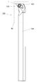
- the cutting tool 101 is a rod-shaped body extending from a first end (upper in FIGS. 6 and 7) to a second end (lower in FIGS. 6 and 7). And the above-mentioned coating tool 1 located in the pocket 103.
- the covering tool 1 is mounted such that a portion used as a cutting edge in the ridge protrudes from the tip of the holder 105.
- the pocket 103 is a portion where the coating tool 1 is mounted, and has a seating surface parallel to the lower surface of the holder 105 and a restraining side surface inclined with respect to the seating surface.
- the pocket 103 is open on the first end side of the holder 105.
- the coating tool 1 is located in the pocket 103. At this time, the lower surface of the coating tool 1 may be in direct contact with the pocket 103, or a sheet may be interposed between the coating tool 1 and the pocket 103.
- the covering tool 1 is mounted such that a portion used as a cutting edge on the ridge projects outward from the holder 105.
- the coating tool 1 is mounted on the holder 105 by screws 107. That is, the screw 107 is inserted into the through hole of the coating tool 1, the tip of the screw 107 is inserted into a screw hole (not shown) formed in the pocket 103, and the screw portions are screwed together.
- the screw 107 is inserted into the through hole of the coating tool 1
- the tip of the screw 107 is inserted into a screw hole (not shown) formed in the pocket 103, and the screw portions are screwed together.
- the holder 105 steel, cast iron, or the like can be used. In particular, it is preferable to use high toughness steel among these members.
- FIGS. 6 and 7 illustrate cutting tools used for so-called turning.
- Turning includes, for example, inner diameter processing, outer diameter processing, and grooving processing.
- the cutting tools are not limited to those used for turning.
- the coated tool 1 of the present disclosure may be used for a cutting tool used for the rolling process.
Landscapes
- Chemical & Material Sciences (AREA)
- Engineering & Computer Science (AREA)
- Mechanical Engineering (AREA)
- Inorganic Chemistry (AREA)
- General Chemical & Material Sciences (AREA)
- Chemical Kinetics & Catalysis (AREA)
- Materials Engineering (AREA)
- Metallurgy (AREA)
- Organic Chemistry (AREA)
- Cutting Tools, Boring Holders, And Turrets (AREA)
- Chemical Vapour Deposition (AREA)
Abstract
Description
本開示は、切削加工に用いられる被覆工具に関する。 The present disclosure relates to a coated tool used for cutting.
旋削加工及び転削加工のような切削加工に用いられる被覆工具としては、例えば特許文献1に記載の被覆工具が知られている。特許文献1に記載の被覆工具は、超硬合金などで構成された基体の表面に、チタン(Ti)の化合物を含有する層(チタン化合物層)及び酸化アルミニウム(Al2O3)を含有する層(酸化アルミニウム層)を備えた被覆層が形成された構成となっている。
2. Description of the Related Art As a coated tool used for cutting such as turning and rolling, for example, a coated tool described in
特許文献1には、チタン化合物層が(112)面に配向することで優れた高温強度を具備すると記載されている。また、特許文献2には、チタン化合物層及び酸化アルミニウム層の界面に複数の空孔が形成されている。これら複数の空孔によって、衝撃緩和効果が得られることが記載されている。
本開示の被覆工具は、第1面を有する基体と、該基体の少なくとも前記第1面の上に位置する被覆層と、を備える。前記被覆層は、前記第1面の上に位置する、チタン化合物を含有する第1層と、該第1層の上に接して位置する、酸化アルミニウムを含有する第2層とを有する。前記第1層の表面の法線に対して前記第1層の結晶粒の結晶面である[112}面の法線がなす傾斜角を測定したとき、0~45°の範囲内にある測定傾斜角を0.25°のピッチ毎に区分するとともに、各区分内に存在する度数を集計してなる傾斜角度数分布グラフにおいて、最高ピークは、0~10°の範囲内に存在する。前記0~10°の範囲内に存在する度数の合計が、前記傾斜角度数分布グラフにおける度数全体の45%以上の割合を占めている。前記第1層は、前記第1面に直交する断面において、前記第1層及び前記第2層の境界に沿った方向に並んで位置する複数の空孔を有する。前記界面に沿う方向における前記空孔の幅の平均値が、隣り合う前記空孔の間隔の平均値よりも小さい。本開示の切削工具は、第1端から第2端に向かって伸びる棒状であり、前記第1端の側に位置するポケットを有するホルダと、前記ポケット内に位置する被覆工具を有する。 被覆 A coated tool of the present disclosure includes a substrate having a first surface, and a coating layer located on at least the first surface of the substrate. The coating layer includes a first layer containing a titanium compound, which is located on the first surface, and a second layer containing aluminum oxide, which is located on and in contact with the first layer. When the inclination angle formed by the normal of the crystal grain of the first layer [112 ° plane] with respect to the normal of the surface of the first layer is within a range of 0 to 45 °. In the inclination angle number distribution graph obtained by dividing the inclination angle into pitches of 0.25 ° and summing up the frequencies present in each section, the highest peak exists in the range of 0 to 10 °. The sum of the frequencies existing in the range of 0 to 10 ° occupies 45% or more of the entire power in the tilt angle number distribution graph. The first layer has a plurality of holes located in a cross section orthogonal to the first surface and arranged in a direction along a boundary between the first layer and the second layer. The average value of the width of the holes in the direction along the interface is smaller than the average value of the interval between the adjacent holes. A cutting tool according to the present disclosure has a rod shape extending from a first end toward a second end, and has a holder having a pocket located on the first end side, and a coating tool located in the pocket.
以下、本開示の被覆工具について、図面を用いて詳細に説明する。但し、以下で参照する各図は、説明の便宜上、本実施形態を説明する上で必要な主要部材のみを簡略化して示したものである。したがって、被覆工具は、参照する各図に示されていない任意の構成部材を備え得る。また、各図中の部材の寸法は、実際の構成部材の寸法及び各部材の寸法比率等を忠実に表したものではない。 Hereinafter, the coated tool of the present disclosure will be described in detail with reference to the drawings. However, in the drawings referred to below, for convenience of description, only main members necessary for describing the present embodiment are simplified. Accordingly, the coating tool may include any components not shown in the referenced figures. Further, the dimensions of the members in the drawings do not faithfully represent the actual dimensions of the constituent members, the dimensional ratios of the respective members, and the like.
<被覆工具>
図1及び図2に示すように、本開示の被覆工具1は、基体3及び被覆層5を備えている。基体3は、第1面7(図2における上面)と、第1面7と隣り合う第2面9(図2における側面)と、第1面7及び第2面9が交わる稜線の少なくとも一部に位置する切刃11とを有している。
<Coated tool>
As shown in FIGS. 1 and 2, a
図1に示す例における基体3は四角板形状であり、第1面7が四角形である。そのため、第2面9の数は4つとなっている。第1面7の少なくとも一部がいわゆるすくい面領域であり、第2面9の少なくとも一部がいわゆる逃げ面領域である。なお、基体3の形状は、四角板形状に限定されるものではなく、例えば第1面7が、三角形、五角形、六角形又は円形であってもよい。また、基体3は、板形状に限定されるものではなく、例えば柱形状であってもよい。
基 体 The
被覆層5は、基体3の少なくとも第1面7の上に位置している。被覆層5は、第1面7のみの上に位置していてもよく、また、基体3における第1面7以外の他の面の上に位置していてもよい。図2に示す例では、第1面7に加えて第2面9の上にも被覆層5が位置している。被覆層5は、切削加工における被覆工具1の耐摩耗性及び耐チッピング性などの特性を向上させるために備えられている。
The
図3に示すように、被覆層5は、第1層13及び第2層15を有している。第1層13は、第1面7の上に位置しており、チタン化合物を含有している。また、第2層15は、第1層13の上に接して位置しており、酸化アルミニウム(Al2O3)を含有している。
As shown in FIG. 3, the
第1層13に含有されているチタン化合物としては、例えば、チタンの炭化物、窒化物、酸化物、炭窒化物、炭酸化物及び炭窒酸化物が挙げられる。第1層13は、上記の化合物のいずれか1つのみを含有する構成であってもよく、また、上記の化合物のうち複数を含有する構成であってもよい。
チ タ ン Examples of the titanium compound contained in the
また、第1層13は、チタン化合物を含有しているものであれば、単層の構成であってもよく、また、複数の層が積層された構成であってもよい。例えば第1層13は、窒化チタン層17と、炭窒化チタン層19とが積層された構成であってもよい。第1層13が基体3に接する層として窒化チタン層17を有している場合には、第1層13と基体3との接合性がさらに高い。なお、窒化チタン層17および炭窒化チタン層19は、それぞれ窒化チタンおよび炭窒化チタンが主成分ということであり、他の成分を含有していてもよい。なお、上記の「主成分」とは、他の成分と比較して質量%の値が最も大きい成分であることを意味している。
The
なお、被覆層5は、第1層13及び第2層15のみによって構成されていてもよく、また、これらの層以外の層を有していてもよい。例えば、基体3及び第1層13の間に別の層が存在していてもよく、また、第2層15の上に別の層が存在していてもよい。
The
また、炭窒化チタン層19が、互いに組成の異なる複数の領域が積層された構成であってもよい。例えば、炭窒化チタン層19が、いわゆるMT(Moderate Temperature)-第1領域19aと、いわゆるHT(high temperature)-第2領域19bとが積層された構成であってもよい。
The
第1層13が第1領域19a及び第2領域19bを有する場合において、第1層13が、第1領域19a及び第2領域19bの間に更に中間領域19cを有していてもよい。なお、上記の層及び領域の境界は、例えば、電子顕微鏡写真(走査型電子顕微鏡(SEM:Scanning Electron Microscope)写真又は透過電子顕微鏡(TEM:Transmission Electron Microscope)写真)を観察することにより、特定することが可能である。その特定は、各層を構成する元素の割合や、結晶の大きさや配向性の差異によって行うことができる。
に お い て When the
また、第2層15に含有されている酸化アルミニウムとしては、例えば、α-アルミナ(α-Al2O3)、γ-アルミナ(γ-Al2O3)及びκ-アルミナ(κ-Al2O3)が挙げられる。これらのうち第2層15がα-アルミナを含有している場合には、被覆工具1の耐熱性を高めることができる。第2層15は、上記の化合物のいずれか1つのみを含有する構成であってもよく、また、上記の化合物のうち複数を含有する構成であってもよい。
Examples of the aluminum oxide contained in the
第2層15に含有されている酸化アルミニウムが上記の化合物のいずれであるかは、例えば、X線回折(XRD:X-Ray Diffraction)分析を行い、ピーク値の分布を観察することによって評価できる。
Which of the above compounds the aluminum oxide contained in the
第1層13におけるチタン化合物の含有比率、及び、第2層15における酸化アルミニウムの含有比率は特定の値に限定されるものではない。一例として、第1層13がチタン化合物を主成分として含有しており、また、第2層15が酸化アルミニウムを主成分として含有している構成が挙げられる。なお、上記の「主成分」とは、上述と同じく、他の成分と比較して質量%の値が最も大きい成分であることを意味している。
The content ratio of the titanium compound in the
第1層13はチタン化合物以外の成分を含有していてもよく、また、第2層15は酸化アルミニウム以外の成分を含有していてもよい。例えば、第1層13が酸化アルミニウムを含有する場合や第2層15がチタン化合物を含有する場合には、第1層13及び第2層15の接合性が向上する。
The
第1層13は、表面の法線に対して結晶粒の結晶面である[112}面の法線がなす傾斜角を測定したとき、0~10°の傾斜角区分範囲内に測定傾斜角の最高ピークが現れ、かつ0~10°の傾斜角区分内に存在する度数の合計割合が、傾斜角度数分布グラフにおける度数全体の45%以上となる傾斜角度数分布グラフを示すように構成することで高温強度を高めることができる。
The
上記の傾斜角の測定は、例えば、後方散乱電子回折(EBSD:Electron Backscatter Diffraction)法を用いた測定によって評価できる。後方散乱電子回折法を用いた測定の一例について以下に示す。 測定 The above-described measurement of the inclination angle can be evaluated by, for example, measurement using an EBSD (Electron Backscatter Diffraction) method. An example of measurement using the backscattered electron diffraction method will be described below.
まず、第1層13の上に存在する第2層15を研削、研磨等により除去し、第1層13を露出させる。次に第1層13を露出させた面に対して研磨加工を施して表面を平滑化させ、測定箇所にイオンミリング処理を行う。
{Circle around (1)} First, the
このようにして露出させた第1層の表面である研磨面に電子線を照射し、約40×25μm2の範囲において0.1μmの間隔で{112}面の法線がなす傾斜角を測定する。次に、測定傾斜角のうち0~45°の範囲内にある測定傾斜角を0.25度のピッチで区分するとよい。 The polished surface, which is the surface of the first layer exposed in this manner, is irradiated with an electron beam, and the tilt angle formed by the normal of the {112} plane at intervals of 0.1 μm in a range of about 40 × 25 μm 2 is measured. I do. Next, the measured tilt angles within the range of 0 to 45 ° among the measured tilt angles may be classified at a pitch of 0.25 degrees.
また、本開示の被覆層5は、図4に示すように、第1相13の内部に空孔21を有している。具体的には、被覆層5が、基体3の第1面7に直交する断面において、第1層13に、第1層13及び第2層15の境界16に沿った方向に並んで位置する複数の空孔21を有している。
被覆 Moreover, the
また、第1面7に直交する断面において、第1面7に平行な方向での空孔21の幅w1の平均値が、隣り合う空孔21の間隔、すなわち第1部分Xの幅w2の平均値よりも小さい。このような構成を有する被覆工具1は、第1部分Xの強度が低下することを抑えつつ、空孔21において高い耐衝撃性を得ることができる。
In a cross section orthogonal to the
そのため、第1層13及び第2層15の接合性の低下を抑えつつ、空孔21によって衝撃を緩和する効果が得られる。
Therefore, the effect of alleviating the impact by the
なお、第1面7に平行な方向での空孔21の幅w1の平均値を評価する際に、第1面7に直交する断面に存在する全ての空孔21の幅w1を評価する必要はなく、断面において並んで位置する10個程度の空孔21の幅w1の平均値によって評価すればよい。例えば、第1面7に直交する断面において第1層13及び第2層15の境界を含む10μm四方の領域を抽出し、この領域における空孔21の幅w1を測定すればよい。また、第1部分Xの幅w2の平均値は、断面において並んで位置する5個程度の空孔21での間隔の平均値によって評価すればよい。
When evaluating the average value of the width w1 of the
空孔21は、第1層13に存在していればよく、例えば、図4に示すように第1層13内に位置している構成だけでなく、又は、図5に示すように第1層13内及び第2層15内のそれぞれに位置している構成であってもよい。図5において、第1層13及び第2層15の境界に沿った仮想線分を一点鎖線で示しており、第2層15内に位置する空孔21が第1層13及び第2層15の境界に沿って位置している。
The
なお、空孔21が第1層13及び第2層15の境界に沿って位置しているとは、複数の空孔21の第1層13及び第2層15の境界までの間隔が、その平均値に対して±20%の範囲に収まっていることをいう。被覆工具1の耐熱性及び耐久性の観点から第1層13がチタン化合物として炭窒化チタンを含有し、さらに、第2層15が酸化アルミニウムとしてα-アルミナを含有している場合において、複数の空孔21が第1層13内に位置している際には被覆工具1の耐久性がさらに高められる。
In addition, that the
これは、α-アルミナと比較して炭窒化チタンの硬度は高いものの耐衝撃性が低いため、空孔21が第1層13内に位置している場合には、第1層13において空孔21による耐衝撃性を高めることができ、被覆工具1の耐久性がさらに高められるからである。
This is because titanium carbonitride has a higher hardness but a lower impact resistance than α-alumina. Therefore, when the
空孔21の大きさは、特に限定されるものではないが、例えば、20~200nmに設定できる。空孔21の大きさが20nm以上である場合には、空孔21による衝撃緩和の効果を高めることができる。また、空孔21の大きさが、200nm以下の場合には、第1層13の強度を維持し易い。なお、本実施形態における空孔21の大きさとは、その空孔21の第1面7に直交する断面における幅w1の最大値を意味する。
大 き The size of the
また、空孔21の形状は、特に限定されるものではないが、第1面7に直交する断面において、第1面7に直交する方向における高さh1よりも第1面7に平行な方向の幅w1が大きい場合、言い換えれば、第1面7に平行な方向での空孔21の幅w1の平均値が、第1面7に直交する方向での空孔21の高さh1の平均値よりも大きい場合には、空孔21の比率を抑えつつ耐衝撃性をさらに高めることができる。これは、以下の理由による。
Further, the shape of the
切削加工物を製造するため被削材を切削加工する際に、被覆層5に対しては第1面7に直交する方向に切削負荷が加わり易い。このとき、空孔21が第1面7に直交する方向の高さh1よりも第1面7に平行な方向の幅w1が大きい形状である場合には、空孔21を必要以上に大きくすることなく、空孔21の広い範囲で切削負荷を吸収することができる。そのため、空孔21の比率を抑えつつ耐衝撃性をさらに高めることができる。
(4) When cutting a work material to produce a cut work, a cutting load is easily applied to the
具体的には、第1面7に平行な方向での空孔21の高さh1の平均値に対する第1面7に直交する方向での空孔21の幅w1の平均値の比率が1.2以上である場合には、空孔21の広い範囲で切削負荷を吸収しやすい。また、上記の比率が2以下である場合には、第1面7に直交する方向での空孔21の変形量が確保され易いので、空孔21において安定して切削負荷を吸収しやすい。
Specifically, the ratio of the average value of the width w1 of the
第1面7に直交する断面での第1面7及び第2面9の境界の最大高さをRzとした際に、第1面7に直交する方向での空孔21の高さh1の平均値がRzよりも小さい場合には、被覆層5の耐久性の低下を抑え易い。
When the maximum height of the boundary between the
第1層13における隣り合う空孔21間に位置する第1部分X及び複数の空孔21が変形することによって本開示の被覆工具1は高い耐衝撃性を備えている。ここで、第1面7に直交する方向での空孔21の幅の平均値がRzよりも小さい場合には、隣り合う空孔21を結ぶ仮想線が、空孔21の幅よりも大きく折れ曲がったジグザグ形状で示される。
被覆 The
仮想線が上記の形状で示される際には、仮に第1部分Xの一つに亀裂が生じた場合であっても、この亀裂が生じた第1部分Xの隣に位置する第1部分Xに亀裂が進展しにくい。そのため、被覆層5の耐久性が低下しにくい。
When the imaginary line is shown in the above shape, even if one of the first portions X has a crack, the first portion X located adjacent to the first portion X where the crack has occurred Cracks are less likely to develop. Therefore, the durability of the
また、第1面7に直交する断面において、空孔21から第1層13及び第2層15の境界までの距離d1の平均値が、第1部分Xの幅w2の平均値よりも大きい場合にも、被覆層5の耐久性が低下しにくい。
Further, in a cross section orthogonal to the
これは、上記の場合においては、第1部分Xと比較して空孔21から第1層13及び第2層15の境界までの距離が十分に確保できるため、仮に第1部分Xの一つに亀裂が生じた場合であっても、この亀裂が第1層13及び第2層15の境界に達しにくいからである。上記の亀裂が第1層13及び第2層15の境界に達しにくいため、第1層13及び第2層15の接合性が低下しにくい。
This is because, in the above case, the distance from the
空孔21は、第1層13に位置しており、第1層13及び第2層15の境界から離れて位置している。ここで、第1面7に直交する断面において、空孔21から第1層13及び第2層15の境界までの距離d1の平均値が、第1面7に直交する方向での空孔21の高さh1の平均値よりも大きい場合には、被覆層5における耐衝撃性を高めつつ第1層13及び第2層15の接合性が低下しにくい。
The
これは、空孔21の大きさと比較して空孔21から第1層13及び第2層15の境界までの距離が十分に確保できるため、切削負荷を吸収するため空孔21が変形する場合であっても、第1層13及び第2層15の境界は変形しない、または、変形量が十分に小さくなるからである。第1層13及び第2層15の境界が大きく変形しにくいため、第1層13及び第2層15の接合性が低下しにくい。
This is because the distance from the
基体3の材質としては、例えば、超硬合金、サーメット及びセラミックスなどの無機材料が挙げられる。なお、基体3の材質としては、これらに限定されるものではない。
材質 Examples of the material of the
超硬合金の組成としては、例えば、WC(炭化タングステン)-Co、WC-TiC(炭化チタン)-Co及びWC-TiC-TaC(炭化タンタル)-Coが挙げられる。ここで、WC、TiC及びTaCは硬質粒子であり、Coは結合相である。また、サーメットは、セラミック成分に金属を複合させた焼結複合材料である。具体的には、サーメットとして、TiCN、TiC又はTiN(窒化チタン)を主成分とした化合物が挙げられる。 組成 The composition of the cemented carbide includes, for example, WC (tungsten carbide) -Co, WC-TiC (titanium carbide) -Co, and WC-TiC-TaC (tantalum carbide) -Co. Here, WC, TiC, and TaC are hard particles, and Co is a binder phase. Cermet is a sintered composite material in which a metal is combined with a ceramic component. Specifically, a compound containing TiCN, TiC, or TiN (titanium nitride) as a main component is used as the cermet.
基体3は、第1面7及び第1面7の反対側に位置する面を貫通する貫通孔23を有していてもよい。貫通孔23は、被覆工具1をホルダに固定するための固定部材を挿入するために用いることができる。固定部材としては、例えばネジ及びクランプ部材が挙げられる。
The
基体3の大きさは特に限定されるものではないが、例えば、本実施形態においては、第1面7の一辺の長さが3~20mm程度に設定される。また、第1面7から第1面7の反対側に位置する面までの高さは5~20mm程度に設定される。
大 き The size of the
<製造方法>
次に、本開示の被覆工具1の製造方法の一例を説明する。
<Production method>
Next, an example of a method for manufacturing the
まず、基体3となる硬質合金を焼成によって形成しうる炭化物、窒化物、炭窒化物及び酸化物などから選択される無機物粉末に、金属粉末、カーボン粉末などを適宜添加及び混合して、混合粉末を作製する。次に、この混合粉末を公知の成形方法を用いて所定の工具形状に成形することによって成形体を作製する。成形方法としては、例えば、プレス成形、鋳込成形、押出成形及び冷間静水圧プレス成形などが挙げられる。上記の成形体を、真空中又は非酸化性雰囲気中にて焼成することによって基体3を作製する。なお、必要に応じて、基体3の表面に研磨加工及びホーニング加工を施してもよい。
First, a metal powder, a carbon powder, and the like are appropriately added to and mixed with an inorganic powder selected from a carbide, a nitride, a carbonitride, an oxide, and the like, which can be formed by firing a hard alloy serving as the
次に、基体3の表面に化学気相蒸着(CVD)法によって被覆層5を成膜する。
Next, a
まず、第1層13における窒化チタン層17(下地層)を成膜する。水素(H2)ガスに、0.5~10体積%の四塩化チタンガスと、10~60体積%の窒素ガスとを混合して、反応ガスとして用いられる第1混合ガスを作製する。第1混合ガスを10~20kPaのガス分圧でチャンバ内に導入し、830~870℃の温度域で窒化チタン層17を成膜する。
First, a titanium nitride layer 17 (base layer) in the
次に、第1層13における第1領域19aを成膜する。水素ガスに、0.5~10体積%の四塩化チタンガスと、1~60体積%の窒素ガスと、0.1~3.0体積%のアセトニトリルガスとを混合し、第2混合ガスを作製する。この第2混合ガスをチャンバ内に導入しながら成膜開始時から、アセトニトリルガスを毎時0.2体積%増加させる。このとき第2混合ガスを、6~12kPaのガス分圧でチャンバ内に導入し、830~870℃の温度域でMT-炭窒化チタンを含有する第1領域19aを成膜する。このようにアセトニトリルガスの量を変化させることで、本開示の被覆工具1を得ることができる。
Next, the
次に、中間領域19cを成膜する。水素ガスに、3体積%~30体積%の四塩化チタンガスと、3体積%~15体積%のメタンガスと、5体積%~10体積%の窒素ガスと、0.5体積%~5体積%の二酸化炭素(CO2)ガスとを混合して、第3混合ガスを作製する。第3混合ガスを6~12kPaのガス分圧でチャンバ内に導入し、980~1050℃の温度域で50~300nm程度の厚みの中間領域19cを成膜する。第3混合ガスが二酸化炭素ガスを含有していることによって、この中間領域19cに空孔21が形成される。上記の条件とすると、第1面7に直交する断面において、第1面7に平行な方向での空孔21の幅w1の平均値が、隣り合う空孔21の間隔w2の平均値よりも小さい被覆工具1を作製できる。
Next, the
また、このとき中間領域19cの厚みが50~300nm程度と薄いため、中間領域19cに形成された空孔21を、第1層13及び第2層15の境界に沿った方向に並んで位置させることが可能となる。
At this time, since the thickness of the
次に、第1層13における第2領域19bを成膜する。水素ガスに、1~4体積%の四塩化チタンガスと、5~20体積%の窒素ガスと、0.1~10体積%のメタンガスと、0.5体積%~10体積%の二酸化炭素ガスとを混合して、第4混合ガスを作製する。第4混合ガスを5~45kPaのガス分圧でチャンバ内に導入し、950~1050℃の温度域で0.3~3μm程度の厚みのHT-炭窒化チタンを含有する第2領域19bを成膜する。
Next, a
次に、第2層15を成膜する。成膜温度を950℃~1100℃、ガス圧を5kPa~20kPaとし、反応ガスの組成が、水素ガスに、5体積%~15体積%の三塩化アルミニウム(AlCl3)ガスと、0.5体積%~2.5体積%の塩化水素(HCl)ガスと、0.5体積%~5.0体積%の二酸化炭素ガスと、0体積%~1体積%の硫化水素(H2S)ガスとを混合して、第5混合ガスを作製する。第5混合ガスをチャンバ内に導入し、第2層15を成膜する。
Next, the
その後、必要に応じて、成膜した被覆層5の表面における切刃11が位置する部分を研磨加工する。このような研磨加工を行った場合には、切刃11への被削材の溶着が抑制され易くなるため、さらに耐欠損性に優れた被覆工具1となる。
(4) Then, if necessary, a portion where the
なお、上記の製造方法は、本開示の被覆工具1を製造する方法の一例である。したがって、本開示の被覆工具1は、上記の製造方法によって作製されたものに限定されないことは言うまでもない。例えば、第2層15の上に別途第3層を成膜してもよい。
The above manufacturing method is an example of a method for manufacturing the
第1面7に直交する断面において、第1面7に平行な方向での空孔21の幅w1の平均値が、第1面7に直交する方向での空孔21の高さh1の平均値よりも大きい被覆工具1を作製するには、中間領域19cの成膜の際に時間調整を行い、50~150nm程度の厚みに成膜することが望ましい。
In a cross section orthogonal to the
第1面7に直交する断面において、空孔21から境界16までの距離d1の平均値が、第1面7に直交する方向での空孔21の高さh1の平均値よりも大きい被覆工具1を作製するには、中間領域19cの成膜の際に時間調整を行い、50~150nm程度の厚みに成膜したのち、第1層13における第2領域19bを成膜する際に時間調整を行い、0.5~3μm程度の厚みに成膜することが望ましい。
In a cross section orthogonal to the
第1面に直交する断面において、空孔21から境界16までの距離d1の平均値が、隣り合う空孔21の間隔w2の平均値よりも大きい被覆工具1を作製するには、第1層13における第2領域19bを成膜する際に時間調整を行い、0.5~3μm程度の厚みに成膜することが望ましい。
In order to produce the
<切削工具>
次に、本開示の切削工具101について図面を用いて説明する。
<Cutting tools>
Next, the
図6及び図7に示すように、切削工具101は、第1端(図6及び7における上)から第2端(図6及び7における下)に向かって延びる棒状体であり、第1端の側に位置するポケット103を有するホルダ105と、ポケット103に位置する上記の被覆工具1とを備えている。本開示の切削工具101においては、稜線における切刃として用いられる部分がホルダ105の先端から突出するように被覆工具1が装着されている。
As shown in FIGS. 6 and 7, the
ポケット103は、被覆工具1が装着される部分であり、ホルダ105の下面に対して平行な着座面と、着座面に対して傾斜する拘束側面とを有している。また、ポケット103は、ホルダ105の第1端側において開口している。
The
ポケット103には被覆工具1が位置している。このとき、被覆工具1の下面がポケット103に直接に接していてもよく、また、被覆工具1とポケット103との間にシートを挟んでいてもよい。
被覆 The
被覆工具1は、稜線における切刃として用いられる部分がホルダ105から外方に突出するように装着される。被覆工具1は、ネジ107によって、ホルダ105に装着されている。すなわち、被覆工具1の貫通孔にネジ107を挿入し、このネジ107の先端をポケット103に形成されたネジ孔(不図示)に挿入してネジ部同士を螺合させることによって、被覆工具1がホルダ105に装着されている。
The
ホルダ105としては、鋼、鋳鉄などを用いることができる。特に、これらの部材の中で靱性の高い鋼を用いることが好ましい。
As the
図6、7に示す例では、いわゆる旋削加工に用いられる切削工具を例示している。旋削加工としては、例えば、内径加工、外径加工及び溝入れ加工が挙げられる。なお、切削工具としては旋削加工に用いられるものに限定されない。例えば、転削加工に用いられる切削工具に本開示の被覆工具1を用いてもよい。
例 The examples shown in FIGS. 6 and 7 illustrate cutting tools used for so-called turning. Turning includes, for example, inner diameter processing, outer diameter processing, and grooving processing. The cutting tools are not limited to those used for turning. For example, the
1・・・被覆工具
3・・・基体
5・・・被覆層
7・・・第1面
9・・・第2面
11・・・切刃
13・・・第1層
15・・・第2層
16・・・第1層及び第2層の境界
17・・・窒化チタン層
19・・・炭窒化チタン層
19a・・第1領域
19b・・第2領域
19c・・中間領域
21・・・空孔
23・・・貫通孔
101・・・切削工具
103・・・ポケット
105・・・ホルダ
107・・・固定ネジ
DESCRIPTION OF
Claims (6)
該基体の少なくとも前記第1面の上に位置する被覆層と、を備えた被覆工具であって、
前記被覆層は、前記第1面の上に位置する、チタン化合物を含有する第1層と、該第1層の上に接して位置する、酸化アルミニウムを含有する第2層とを有し、
前記第1層の表面の法線に対して前記第1層の結晶粒の結晶面である[112}面の法線がなす傾斜角を測定したとき、0~45°の範囲内にある測定傾斜角を0.25°のピッチ毎に区分するとともに、各区分内に存在する度数を集計してなる傾斜角度数分布グラフにおいて、最高ピークは、0~10°の範囲内に存在し、前記0~10°の範囲内に存在する度数の合計が、前記傾斜角度数分布グラフにおける度数全体の45%以上の割合を占めており、
前記第1層は、前記第1面に直交する断面において、前記第1層及び前記第2層の境界に沿った方向に並んで位置する複数の空孔を有し、前記界面に沿う方向における前記空孔の幅の平均値が、隣り合う前記空孔の間隔の平均値よりも小さい、被覆工具。 A substrate having a first surface;
A coating layer located on at least the first surface of the substrate, comprising:
The coating layer includes a first layer containing a titanium compound, which is located on the first surface, and a second layer containing aluminum oxide, which is located on and in contact with the first layer,
When the inclination angle formed by the normal of the crystal plane of the crystal grains of the first layer with respect to the normal of the surface of the first layer is [0 ° to 45 °] In the inclination angle number distribution graph obtained by dividing the inclination angle for each pitch of 0.25 ° and summing up the frequencies existing in each section, the highest peak exists in the range of 0 to 10 °. The sum of the frequencies existing in the range of 0 to 10 ° occupies a ratio of 45% or more of the entire frequencies in the inclination angle number distribution graph,
The first layer has, in a cross section orthogonal to the first surface, a plurality of holes positioned in a direction along a boundary between the first layer and the second layer, and in a direction along the interface. The coated tool, wherein the average value of the width of the holes is smaller than the average value of the interval between the adjacent holes.
前記ポケット内に位置する、請求項1~5のいずれか1つに記載の被覆工具とを有する切削工具。 A holder having a rod shape extending from the first end toward the second end and having a pocket located on the side of the first end;
A cutting tool comprising: the coated tool according to any one of claims 1 to 5, which is located in the pocket.
Priority Applications (4)
| Application Number | Priority Date | Filing Date | Title |
|---|---|---|---|
| US17/273,763 US12030127B2 (en) | 2018-09-05 | 2019-09-03 | Coated tool and cutting tool |
| JP2020541233A JP7089039B2 (en) | 2018-09-05 | 2019-09-03 | Covering tools and cutting tools |
| CN201980058691.1A CN112672839B (en) | 2018-09-05 | 2019-09-03 | Coated tools and cutting tools |
| DE112019004436.2T DE112019004436T5 (en) | 2018-09-05 | 2019-09-03 | COATED TOOL AND CUTTING TOOL |
Applications Claiming Priority (2)
| Application Number | Priority Date | Filing Date | Title |
|---|---|---|---|
| JP2018-166093 | 2018-09-05 | ||
| JP2018166093 | 2018-09-05 |
Publications (1)
| Publication Number | Publication Date |
|---|---|
| WO2020050263A1 true WO2020050263A1 (en) | 2020-03-12 |
Family
ID=69722336
Family Applications (1)
| Application Number | Title | Priority Date | Filing Date |
|---|---|---|---|
| PCT/JP2019/034599 Ceased WO2020050263A1 (en) | 2018-09-05 | 2019-09-03 | Coated tool and cutting tool |
Country Status (5)
| Country | Link |
|---|---|
| US (1) | US12030127B2 (en) |
| JP (1) | JP7089039B2 (en) |
| CN (1) | CN112672839B (en) |
| DE (1) | DE112019004436T5 (en) |
| WO (1) | WO2020050263A1 (en) |
Families Citing this family (5)
| Publication number | Priority date | Publication date | Assignee | Title |
|---|---|---|---|---|
| US11992883B2 (en) | 2018-09-05 | 2024-05-28 | Kyocera Corporation | Coated tool and cutting tool |
| US11998991B2 (en) | 2018-09-05 | 2024-06-04 | Kyocera Corporation | Coated tool and cutting tool |
| WO2020050261A1 (en) | 2018-09-05 | 2020-03-12 | 京セラ株式会社 | Coated tool and cutting tool |
| WO2020050260A1 (en) | 2018-09-05 | 2020-03-12 | 京セラ株式会社 | Coated tool and cutting tool |
| US12115586B2 (en) | 2018-09-05 | 2024-10-15 | Kyocera Corporation | Coated tool and cutting tool |
Citations (7)
| Publication number | Priority date | Publication date | Assignee | Title |
|---|---|---|---|---|
| JP2006015426A (en) * | 2004-06-30 | 2006-01-19 | Mitsubishi Materials Corp | Surface coated cermet cutting tool with excellent chipping resistance with a hard coating layer in high-speed intermittent cutting |
| JP2006116621A (en) * | 2004-10-19 | 2006-05-11 | Mitsubishi Materials Corp | Surface coated cermet cutting tool with excellent chipping resistance with a hard coating layer in high-speed intermittent cutting |
| JP2006231422A (en) * | 2005-02-22 | 2006-09-07 | Mitsubishi Materials Corp | Surface coated cermet cutting tool with excellent chipping resistance with a hard coating layer in high-speed intermittent cutting |
| JP2012187659A (en) * | 2011-03-10 | 2012-10-04 | Mitsubishi Materials Corp | Surface coated cutting tool with hard coating layer having superior chipping resistance and fracture resistance |
| JP2013126709A (en) * | 2011-02-03 | 2013-06-27 | Mitsubishi Materials Corp | Surface-coated cutting tool having hard-coating layer with excellent chipping resistance and fracturing resistance |
| WO2017146200A1 (en) * | 2016-02-24 | 2017-08-31 | 京セラ株式会社 | Coated tool |
| WO2018181034A1 (en) * | 2017-03-29 | 2018-10-04 | 京セラ株式会社 | Coated tool and cutting tool |
Family Cites Families (38)
| Publication number | Priority date | Publication date | Assignee | Title |
|---|---|---|---|---|
| DE69431032T2 (en) | 1993-05-31 | 2003-01-30 | Sumitomo Electric Industries, Ltd. | COATED CUTTING TOOL AND METHOD FOR THE PRODUCTION THEREOF |
| JP3384110B2 (en) | 1993-05-31 | 2003-03-10 | 住友電気工業株式会社 | Coated cutting tool and its manufacturing method |
| JP3478358B2 (en) | 1995-04-28 | 2003-12-15 | 三菱マテリアル株式会社 | Composite hard layer surface coated cutting tool |
| JP2000071108A (en) | 1998-08-31 | 2000-03-07 | Mitsubishi Materials Corp | Surface coated cemented carbide cutting tool with a hard coating layer that exhibits excellent delamination resistance |
| SE516071C2 (en) | 1999-04-26 | 2001-11-12 | Sandvik Ab | Carbide inserts coated with a durable coating |
| IL145465A (en) | 1999-06-21 | 2005-03-20 | Sumitomo Electric Industries | Coated hard alloy |
| CA2476780A1 (en) | 2002-02-21 | 2003-08-28 | Element Six (Pty) Ltd. | Tool insert |
| WO2006104004A1 (en) | 2005-03-28 | 2006-10-05 | Kyocera Corporation | Super hard alloy and cutting tool |
| JP5239292B2 (en) * | 2007-10-26 | 2013-07-17 | 三菱マテリアル株式会社 | Surface-coated cutting tool with excellent fracture resistance due to hard coating layer |
| JP5035479B2 (en) * | 2011-01-27 | 2012-09-26 | 三菱マテリアル株式会社 | Surface coated cutting tool with excellent chipping resistance and wear resistance |
| US8574728B2 (en) * | 2011-03-15 | 2013-11-05 | Kennametal Inc. | Aluminum oxynitride coated article and method of making the same |
| JP5884138B2 (en) | 2011-04-21 | 2016-03-15 | 住友電工ハードメタル株式会社 | Surface-coated cutting tool and manufacturing method thereof |
| DE102011053705A1 (en) | 2011-09-16 | 2013-03-21 | Walter Ag | Cutting insert and method for its production |
| EP2604720A1 (en) | 2011-12-14 | 2013-06-19 | Sandvik Intellectual Property Ab | Coated cutting tool and method of manufacturing the same |
| CN103173761B (en) * | 2011-12-23 | 2015-08-19 | 株洲钻石切削刀具股份有限公司 | Cutting tool improving coating structure and preparation method thereof |
| JP5892473B2 (en) * | 2012-09-13 | 2016-03-23 | 三菱マテリアル株式会社 | A surface-coated cutting tool with a hard coating layer that exhibits excellent peeling and chipping resistance in high-speed intermittent cutting. |
| JP5930512B2 (en) * | 2012-09-13 | 2016-06-08 | 三菱マテリアル株式会社 | A surface-coated cutting tool with a hard coating layer that exhibits excellent peeling and chipping resistance in high-speed intermittent cutting. |
| DE102013005437A1 (en) | 2013-03-29 | 2014-10-02 | Empa | Hard material layers with selected thermal conductivity |
| EP2818573B1 (en) * | 2013-06-27 | 2016-02-03 | Sandvik Intellectual Property AB | Coated cutting tool |
| JP6198141B2 (en) * | 2014-03-26 | 2017-09-20 | 三菱マテリアル株式会社 | Surface coated cutting tool with excellent chipping resistance and chipping resistance with excellent hard coating layer |
| JP6198006B2 (en) | 2014-03-28 | 2017-09-20 | 三菱マテリアル株式会社 | Surface coated cutting tool with excellent abnormal damage resistance |
| RU2704949C2 (en) | 2014-12-19 | 2019-10-31 | Сандвик Интеллекчуал Проперти Аб | Cvd coated cutting tool |
| JP6419220B2 (en) * | 2015-01-28 | 2018-11-07 | 京セラ株式会社 | Coated tool |
| JP2016137550A (en) * | 2015-01-28 | 2016-08-04 | 三菱マテリアル株式会社 | Surface-coated cutting tool exhibiting excellent chipping resistance in high-speed high cut-in intermittent cutting |
| JP6519952B2 (en) * | 2015-07-30 | 2019-05-29 | 三菱マテリアル株式会社 | Surface coated cutting tool exhibiting excellent chipping resistance with hard coating layer |
| JP5872747B1 (en) * | 2015-08-28 | 2016-03-01 | 住友電工ハードメタル株式会社 | Surface coated cutting tool |
| US9844816B2 (en) | 2015-10-09 | 2017-12-19 | Sumitomo Electric Hardmetal Corp. | Surface-coated cutting tool |
| WO2017090765A1 (en) * | 2015-11-28 | 2017-06-01 | 京セラ株式会社 | Cutting tool |
| JP6507456B2 (en) | 2016-01-08 | 2019-05-08 | 住友電工ハードメタル株式会社 | Method of manufacturing surface coated cutting tool |
| WO2017204141A1 (en) | 2016-05-24 | 2017-11-30 | 株式会社タンガロイ | Coated cutting tool |
| JP6699056B2 (en) | 2016-06-14 | 2020-05-27 | 住友電工ハードメタル株式会社 | Surface coated cutting tool |
| JP6784389B2 (en) * | 2016-08-26 | 2020-11-11 | 三菱マテリアル株式会社 | Surface coating cutting tool with excellent chipping resistance and wear resistance with a hard coating layer |
| JP2018103288A (en) | 2016-12-26 | 2018-07-05 | 京セラ株式会社 | Cutting insert |
| US12115586B2 (en) | 2018-09-05 | 2024-10-15 | Kyocera Corporation | Coated tool and cutting tool |
| WO2020050261A1 (en) | 2018-09-05 | 2020-03-12 | 京セラ株式会社 | Coated tool and cutting tool |
| US11998991B2 (en) | 2018-09-05 | 2024-06-04 | Kyocera Corporation | Coated tool and cutting tool |
| WO2020050260A1 (en) | 2018-09-05 | 2020-03-12 | 京セラ株式会社 | Coated tool and cutting tool |
| US11992883B2 (en) | 2018-09-05 | 2024-05-28 | Kyocera Corporation | Coated tool and cutting tool |
-
2019
- 2019-09-03 WO PCT/JP2019/034599 patent/WO2020050263A1/en not_active Ceased
- 2019-09-03 DE DE112019004436.2T patent/DE112019004436T5/en active Pending
- 2019-09-03 US US17/273,763 patent/US12030127B2/en active Active
- 2019-09-03 CN CN201980058691.1A patent/CN112672839B/en active Active
- 2019-09-03 JP JP2020541233A patent/JP7089039B2/en active Active
Patent Citations (7)
| Publication number | Priority date | Publication date | Assignee | Title |
|---|---|---|---|---|
| JP2006015426A (en) * | 2004-06-30 | 2006-01-19 | Mitsubishi Materials Corp | Surface coated cermet cutting tool with excellent chipping resistance with a hard coating layer in high-speed intermittent cutting |
| JP2006116621A (en) * | 2004-10-19 | 2006-05-11 | Mitsubishi Materials Corp | Surface coated cermet cutting tool with excellent chipping resistance with a hard coating layer in high-speed intermittent cutting |
| JP2006231422A (en) * | 2005-02-22 | 2006-09-07 | Mitsubishi Materials Corp | Surface coated cermet cutting tool with excellent chipping resistance with a hard coating layer in high-speed intermittent cutting |
| JP2013126709A (en) * | 2011-02-03 | 2013-06-27 | Mitsubishi Materials Corp | Surface-coated cutting tool having hard-coating layer with excellent chipping resistance and fracturing resistance |
| JP2012187659A (en) * | 2011-03-10 | 2012-10-04 | Mitsubishi Materials Corp | Surface coated cutting tool with hard coating layer having superior chipping resistance and fracture resistance |
| WO2017146200A1 (en) * | 2016-02-24 | 2017-08-31 | 京セラ株式会社 | Coated tool |
| WO2018181034A1 (en) * | 2017-03-29 | 2018-10-04 | 京セラ株式会社 | Coated tool and cutting tool |
Also Published As
| Publication number | Publication date |
|---|---|
| CN112672839A (en) | 2021-04-16 |
| US12030127B2 (en) | 2024-07-09 |
| CN112672839B (en) | 2024-02-23 |
| JPWO2020050263A1 (en) | 2021-09-02 |
| JP7089039B2 (en) | 2022-06-21 |
| DE112019004436T5 (en) | 2021-05-20 |
| US20210220920A1 (en) | 2021-07-22 |
Similar Documents
| Publication | Publication Date | Title |
|---|---|---|
| JP7089039B2 (en) | Covering tools and cutting tools | |
| JP7133629B2 (en) | coated tools and cutting tools | |
| JP7261806B2 (en) | coated tools and cutting tools | |
| JP7018934B2 (en) | Covering tools and cutting tools | |
| JP7261805B2 (en) | coated tools and cutting tools | |
| JP7089038B2 (en) | Covering tools and cutting tools | |
| JP7142097B2 (en) | coated tools and cutting tools | |
| JPWO2018092791A1 (en) | Cutting insert and cutting tool | |
| WO2019004018A1 (en) | Coated tool, cutting tool, and method for manufacturing cut workpiece | |
| JPWO2018181272A1 (en) | Coated and cutting tools | |
| JP2008178943A (en) | Surface coated cutting tool whose hard coating layer exhibits excellent wear resistance in intermittent high feed cutting | |
| JP7142098B2 (en) | coated tools and cutting tools | |
| JP7142099B2 (en) | coated tools and cutting tools | |
| JP7523567B2 (en) | Coated tool and cutting tool equipped with same | |
| JP2014136268A (en) | Surface coating cutting tool with hard coating layer exhibiting superior chipping resistance in heavy intermittent cutting |
Legal Events
| Date | Code | Title | Description |
|---|---|---|---|
| 121 | Ep: the epo has been informed by wipo that ep was designated in this application |
Ref document number: 19856923 Country of ref document: EP Kind code of ref document: A1 |
|
| ENP | Entry into the national phase |
Ref document number: 2020541233 Country of ref document: JP Kind code of ref document: A |
|
| 122 | Ep: pct application non-entry in european phase |
Ref document number: 19856923 Country of ref document: EP Kind code of ref document: A1 |