WO2011161464A1 - Volatile liquid emanation device with capillary - Google Patents
Volatile liquid emanation device with capillary Download PDFInfo
- Publication number
- WO2011161464A1 WO2011161464A1 PCT/GB2011/051190 GB2011051190W WO2011161464A1 WO 2011161464 A1 WO2011161464 A1 WO 2011161464A1 GB 2011051190 W GB2011051190 W GB 2011051190W WO 2011161464 A1 WO2011161464 A1 WO 2011161464A1
- Authority
- WO
- WIPO (PCT)
- Prior art keywords
- reservoir
- emanation
- volatile liquid
- delivery mechanism
- fluid communication
- Prior art date
- Legal status (The legal status is an assumption and is not a legal conclusion. Google has not performed a legal analysis and makes no representation as to the accuracy of the status listed.)
- Ceased
Links
Classifications
-
- A—HUMAN NECESSITIES
- A61—MEDICAL OR VETERINARY SCIENCE; HYGIENE
- A61L—METHODS OR APPARATUS FOR STERILISING MATERIALS OR OBJECTS IN GENERAL; DISINFECTION, STERILISATION OR DEODORISATION OF AIR; CHEMICAL ASPECTS OF BANDAGES, DRESSINGS, ABSORBENT PADS OR SURGICAL ARTICLES; MATERIALS FOR BANDAGES, DRESSINGS, ABSORBENT PADS OR SURGICAL ARTICLES
- A61L9/00—Disinfection, sterilisation or deodorisation of air
- A61L9/015—Disinfection, sterilisation or deodorisation of air using gaseous or vaporous substances, e.g. ozone
- A61L9/04—Disinfection, sterilisation or deodorisation of air using gaseous or vaporous substances, e.g. ozone using substances evaporated in the air without heating
- A61L9/12—Apparatus, e.g. holders, therefor
- A61L9/127—Apparatus, e.g. holders, therefor comprising a wick
-
- A—HUMAN NECESSITIES
- A01—AGRICULTURE; FORESTRY; ANIMAL HUSBANDRY; HUNTING; TRAPPING; FISHING
- A01M—CATCHING, TRAPPING OR SCARING OF ANIMALS; APPARATUS FOR THE DESTRUCTION OF NOXIOUS ANIMALS OR NOXIOUS PLANTS
- A01M1/00—Stationary means for catching or killing insects
- A01M1/20—Poisoning, narcotising, or burning insects
- A01M1/2022—Poisoning or narcotising insects by vaporising an insecticide
- A01M1/2027—Poisoning or narcotising insects by vaporising an insecticide without heating
-
- A—HUMAN NECESSITIES
- A01—AGRICULTURE; FORESTRY; ANIMAL HUSBANDRY; HUNTING; TRAPPING; FISHING
- A01M—CATCHING, TRAPPING OR SCARING OF ANIMALS; APPARATUS FOR THE DESTRUCTION OF NOXIOUS ANIMALS OR NOXIOUS PLANTS
- A01M1/00—Stationary means for catching or killing insects
- A01M1/20—Poisoning, narcotising, or burning insects
- A01M1/2022—Poisoning or narcotising insects by vaporising an insecticide
- A01M1/2027—Poisoning or narcotising insects by vaporising an insecticide without heating
- A01M1/2044—Holders or dispensers for liquid insecticide, e.g. using wicks
- A01M1/205—Holders or dispensers for liquid insecticide, e.g. using wicks using vibrations, e.g. ultrasonic or piezoelectric atomizers
-
- A—HUMAN NECESSITIES
- A01—AGRICULTURE; FORESTRY; ANIMAL HUSBANDRY; HUNTING; TRAPPING; FISHING
- A01M—CATCHING, TRAPPING OR SCARING OF ANIMALS; APPARATUS FOR THE DESTRUCTION OF NOXIOUS ANIMALS OR NOXIOUS PLANTS
- A01M1/00—Stationary means for catching or killing insects
- A01M1/20—Poisoning, narcotising, or burning insects
- A01M1/2022—Poisoning or narcotising insects by vaporising an insecticide
- A01M1/2061—Poisoning or narcotising insects by vaporising an insecticide using a heat source
- A01M1/2077—Poisoning or narcotising insects by vaporising an insecticide using a heat source using an electrical resistance as heat source
-
- A—HUMAN NECESSITIES
- A61—MEDICAL OR VETERINARY SCIENCE; HYGIENE
- A61L—METHODS OR APPARATUS FOR STERILISING MATERIALS OR OBJECTS IN GENERAL; DISINFECTION, STERILISATION OR DEODORISATION OF AIR; CHEMICAL ASPECTS OF BANDAGES, DRESSINGS, ABSORBENT PADS OR SURGICAL ARTICLES; MATERIALS FOR BANDAGES, DRESSINGS, ABSORBENT PADS OR SURGICAL ARTICLES
- A61L9/00—Disinfection, sterilisation or deodorisation of air
- A61L9/015—Disinfection, sterilisation or deodorisation of air using gaseous or vaporous substances, e.g. ozone
- A61L9/02—Disinfection, sterilisation or deodorisation of air using gaseous or vaporous substances, e.g. ozone using substances evaporated in the air by heating or combustion
- A61L9/03—Apparatus therefor
-
- A—HUMAN NECESSITIES
- A61—MEDICAL OR VETERINARY SCIENCE; HYGIENE
- A61L—METHODS OR APPARATUS FOR STERILISING MATERIALS OR OBJECTS IN GENERAL; DISINFECTION, STERILISATION OR DEODORISATION OF AIR; CHEMICAL ASPECTS OF BANDAGES, DRESSINGS, ABSORBENT PADS OR SURGICAL ARTICLES; MATERIALS FOR BANDAGES, DRESSINGS, ABSORBENT PADS OR SURGICAL ARTICLES
- A61L9/00—Disinfection, sterilisation or deodorisation of air
- A61L9/015—Disinfection, sterilisation or deodorisation of air using gaseous or vaporous substances, e.g. ozone
- A61L9/02—Disinfection, sterilisation or deodorisation of air using gaseous or vaporous substances, e.g. ozone using substances evaporated in the air by heating or combustion
- A61L9/03—Apparatus therefor
- A61L9/037—Apparatus therefor comprising a wick
-
- A—HUMAN NECESSITIES
- A61—MEDICAL OR VETERINARY SCIENCE; HYGIENE
- A61L—METHODS OR APPARATUS FOR STERILISING MATERIALS OR OBJECTS IN GENERAL; DISINFECTION, STERILISATION OR DEODORISATION OF AIR; CHEMICAL ASPECTS OF BANDAGES, DRESSINGS, ABSORBENT PADS OR SURGICAL ARTICLES; MATERIALS FOR BANDAGES, DRESSINGS, ABSORBENT PADS OR SURGICAL ARTICLES
- A61L9/00—Disinfection, sterilisation or deodorisation of air
- A61L9/015—Disinfection, sterilisation or deodorisation of air using gaseous or vaporous substances, e.g. ozone
- A61L9/04—Disinfection, sterilisation or deodorisation of air using gaseous or vaporous substances, e.g. ozone using substances evaporated in the air without heating
- A61L9/12—Apparatus, e.g. holders, therefor
-
- A—HUMAN NECESSITIES
- A61—MEDICAL OR VETERINARY SCIENCE; HYGIENE
- A61L—METHODS OR APPARATUS FOR STERILISING MATERIALS OR OBJECTS IN GENERAL; DISINFECTION, STERILISATION OR DEODORISATION OF AIR; CHEMICAL ASPECTS OF BANDAGES, DRESSINGS, ABSORBENT PADS OR SURGICAL ARTICLES; MATERIALS FOR BANDAGES, DRESSINGS, ABSORBENT PADS OR SURGICAL ARTICLES
- A61L9/00—Disinfection, sterilisation or deodorisation of air
- A61L9/14—Disinfection, sterilisation or deodorisation of air using sprayed or atomised substances including air-liquid contact processes
-
- A—HUMAN NECESSITIES
- A61—MEDICAL OR VETERINARY SCIENCE; HYGIENE
- A61M—DEVICES FOR INTRODUCING MEDIA INTO, OR ONTO, THE BODY; DEVICES FOR TRANSDUCING BODY MEDIA OR FOR TAKING MEDIA FROM THE BODY; DEVICES FOR PRODUCING OR ENDING SLEEP OR STUPOR
- A61M11/00—Sprayers or atomisers specially adapted for therapeutic purposes
-
- A—HUMAN NECESSITIES
- A61—MEDICAL OR VETERINARY SCIENCE; HYGIENE
- A61M—DEVICES FOR INTRODUCING MEDIA INTO, OR ONTO, THE BODY; DEVICES FOR TRANSDUCING BODY MEDIA OR FOR TAKING MEDIA FROM THE BODY; DEVICES FOR PRODUCING OR ENDING SLEEP OR STUPOR
- A61M11/00—Sprayers or atomisers specially adapted for therapeutic purposes
- A61M11/005—Sprayers or atomisers specially adapted for therapeutic purposes using ultrasonics
-
- A—HUMAN NECESSITIES
- A61—MEDICAL OR VETERINARY SCIENCE; HYGIENE
- A61M—DEVICES FOR INTRODUCING MEDIA INTO, OR ONTO, THE BODY; DEVICES FOR TRANSDUCING BODY MEDIA OR FOR TAKING MEDIA FROM THE BODY; DEVICES FOR PRODUCING OR ENDING SLEEP OR STUPOR
- A61M11/00—Sprayers or atomisers specially adapted for therapeutic purposes
- A61M11/04—Sprayers or atomisers specially adapted for therapeutic purposes operated by the vapour pressure of the liquid to be sprayed or atomised
- A61M11/041—Sprayers or atomisers specially adapted for therapeutic purposes operated by the vapour pressure of the liquid to be sprayed or atomised using heaters
-
- A—HUMAN NECESSITIES
- A61—MEDICAL OR VETERINARY SCIENCE; HYGIENE
- A61M—DEVICES FOR INTRODUCING MEDIA INTO, OR ONTO, THE BODY; DEVICES FOR TRANSDUCING BODY MEDIA OR FOR TAKING MEDIA FROM THE BODY; DEVICES FOR PRODUCING OR ENDING SLEEP OR STUPOR
- A61M11/00—Sprayers or atomisers specially adapted for therapeutic purposes
- A61M11/04—Sprayers or atomisers specially adapted for therapeutic purposes operated by the vapour pressure of the liquid to be sprayed or atomised
- A61M11/041—Sprayers or atomisers specially adapted for therapeutic purposes operated by the vapour pressure of the liquid to be sprayed or atomised using heaters
- A61M11/042—Sprayers or atomisers specially adapted for therapeutic purposes operated by the vapour pressure of the liquid to be sprayed or atomised using heaters electrical
-
- A—HUMAN NECESSITIES
- A61—MEDICAL OR VETERINARY SCIENCE; HYGIENE
- A61L—METHODS OR APPARATUS FOR STERILISING MATERIALS OR OBJECTS IN GENERAL; DISINFECTION, STERILISATION OR DEODORISATION OF AIR; CHEMICAL ASPECTS OF BANDAGES, DRESSINGS, ABSORBENT PADS OR SURGICAL ARTICLES; MATERIALS FOR BANDAGES, DRESSINGS, ABSORBENT PADS OR SURGICAL ARTICLES
- A61L2209/00—Aspects relating to disinfection, sterilisation or deodorisation of air
- A61L2209/10—Apparatus features
- A61L2209/13—Dispensing or storing means for active compounds
- A61L2209/132—Piezo or ultrasonic elements for dispensing
-
- A—HUMAN NECESSITIES
- A61—MEDICAL OR VETERINARY SCIENCE; HYGIENE
- A61L—METHODS OR APPARATUS FOR STERILISING MATERIALS OR OBJECTS IN GENERAL; DISINFECTION, STERILISATION OR DEODORISATION OF AIR; CHEMICAL ASPECTS OF BANDAGES, DRESSINGS, ABSORBENT PADS OR SURGICAL ARTICLES; MATERIALS FOR BANDAGES, DRESSINGS, ABSORBENT PADS OR SURGICAL ARTICLES
- A61L2209/00—Aspects relating to disinfection, sterilisation or deodorisation of air
- A61L2209/10—Apparatus features
- A61L2209/13—Dispensing or storing means for active compounds
- A61L2209/133—Replaceable cartridges, refills
-
- A—HUMAN NECESSITIES
- A61—MEDICAL OR VETERINARY SCIENCE; HYGIENE
- A61M—DEVICES FOR INTRODUCING MEDIA INTO, OR ONTO, THE BODY; DEVICES FOR TRANSDUCING BODY MEDIA OR FOR TAKING MEDIA FROM THE BODY; DEVICES FOR PRODUCING OR ENDING SLEEP OR STUPOR
- A61M2205/00—General characteristics of the apparatus
- A61M2205/36—General characteristics of the apparatus related to heating or cooling
- A61M2205/3653—General characteristics of the apparatus related to heating or cooling by Joule effect, i.e. electric resistance
-
- A—HUMAN NECESSITIES
- A61—MEDICAL OR VETERINARY SCIENCE; HYGIENE
- A61M—DEVICES FOR INTRODUCING MEDIA INTO, OR ONTO, THE BODY; DEVICES FOR TRANSDUCING BODY MEDIA OR FOR TAKING MEDIA FROM THE BODY; DEVICES FOR PRODUCING OR ENDING SLEEP OR STUPOR
- A61M2205/00—General characteristics of the apparatus
- A61M2205/36—General characteristics of the apparatus related to heating or cooling
- A61M2205/3693—General characteristics of the apparatus related to heating or cooling by mechanical waves, e.g. ultrasonic
-
- A—HUMAN NECESSITIES
- A61—MEDICAL OR VETERINARY SCIENCE; HYGIENE
- A61M—DEVICES FOR INTRODUCING MEDIA INTO, OR ONTO, THE BODY; DEVICES FOR TRANSDUCING BODY MEDIA OR FOR TAKING MEDIA FROM THE BODY; DEVICES FOR PRODUCING OR ENDING SLEEP OR STUPOR
- A61M2205/00—General characteristics of the apparatus
- A61M2205/82—Internal energy supply devices
- A61M2205/8206—Internal energy supply devices battery-operated
Definitions
- the present invention relates to a volatile liquid delivery mechanism for an emanation device wherein said volatile liquids comprise active components such as fragrances, insecticides, fungicides, pesticides, sanitizing materials and pharmaceuticals are provided, and particularly the present invention relates to a passive, non-powered volatile liquid delivery mechanism for a powered emanation device.
- a further drawback associated with devices having a membrane in constant contact with a volatile material, such as a volatile liquid air freshener, is the phenomena of vacuum build-up.
- the vacuum build-up phenomena can occur inside the housing due to the wetted membrane being unable to allow sufficient flow of air therethrough in order to equalise the drop in pressure inside the housing caused by the emanation of the volatile material. This build-up phenomena can cause unacceptable performance problems with such a device from a consumer perspective.
- a volatile liquid fragrance/air freshener comprising several components. These components often possess different volatilities which can lead to emission problems. In devices having a membrane in constant contact with the volatile liquid, an accumulation of volatile liquid components with the lowest comparative volatilities can occur leading to an undesirable non-uniform emanation profile for the liquid. In either or both cases of build-up phenomena and accumulation of low volatility components, the evaporation rate, and thus the emanation rate, of the volatile liquid adopts the profile shown in
- the emanation rate may reach equilibrium (dashed line) where the rate of evaporation of each individual component of the volatile liquid away from the membrane surface is equivalent to the rate of deposition due to diffusion and the device cannot maintain any further vacuum.
- a further drawback with known passive volatile liquid emanators is that prolonged exposure of the volatile liquid to a wicking material, such as a membrane or the like, can cause fractionation over time due to various factors such as the wicking material having a limited porosity affecting liquid transfer rates/evaporation rates which , in turn, can change the character and/or intensity of the volatile liquid being emanated. Changes in character of emanated volatile liquids is particularly noticeable for fragrances wherein common wicking materials cause the 'high notes' of a fragrance to be evaporated when the wicking material is first exposed to the fragranced liquid, and the 'low notes' are evaporated thereafter which affects the user's experience.
- an emanation device for emanating a volatile liquid containing one or more active materials wherein the active material comprises at least one of: a fragrance; an insecticide; a fungicide; a pesticide; a sanitising material; and/or a pharmaceutical;
- the emanation device comprises:
- housing is arranged to support the passive delivery mechanism in spatial arrangement over the emanation means
- the delivery mechanism comprises:
- one or more capillary tubes in fluid communication with the reservoir at one end thereof wherein said one or more capillary tubes are in non-valved fluid communication with the reservoir; and a nozzle located at the end of the or each capillary tube(s) remote from the reservoir wherein the or each nozzle is in non-valved fluid communication with the or each capillary tube(s).
- non-valved should be understood as meaning that that component of the device has no mechanical features which enable it to regulate or adjust the flow of liquid therethrough.
- passive should be understood as meaning that that the delivery mechanism is operable without a power source or some other means which drives the delivery of the volatile liquid to the emanation means; in other words the delivery mechanism of the present invention only requires gravity in order deliver volatile liquid to the emanation means.
- an emanation device comprising: a housing;
- housing is arranged to support the passive delivery mechanism in spatial arrangement over the emanation means
- the delivery mechanism comprises:
- a volatile liquid reservoir holding a volatile liquid containing one or more active materials wherein the active material comprises at least one of: a fragrance; an insecticide; a fungicide; a pesticide; a sanitising material; and/or a pharmaceutical;
- one or more capillary tubes in fluid communication with the reservoir at one end thereof wherein said one or more capillary tubes are in non-valved fluid communication with the reservoir; and a nozzle located at the end of the or each capillary tube(s) remote from the reservoir wherein the or each nozzle is in non-valved fluid communication with the or each capillary tube(s).
- a passive delivery mechanism for an emanation device wherein the delivery mechanism is connectable, preferably releaseably connectable, to a housing of the emanation device and wherein the passive delivery mechanism comprises:
- a volatile liquid reservoir holding a volatile liquid containing one or more active materials wherein the active material comprises at least one of: a fragrance; an insecticide; a fungicide; a pesticide; a sanitising material; and/or a pharmaceutical;
- one or more capillary tubes in fluid communication with the reservoir at one end thereof wherein said one or more capillary tubes are in non-valved fluid communication with the reservoir;
- a nozzle located at the end of the or each capillary tube(s) remote from the reservoir wherein the or each nozzle is in non-valved fluid communication with the or each capillary tube(s).
- a method of providing a non-valved flow rate of volatile liquid between substantially 0.1 - 500//L/hr on to an emanation means comprises the steps of placing a device according to the second aspect of the present invention in a location where emanation of the volatile liquid is desired and causing the non-valved flow of liquid from the passive delivery mechanism toward the emanation means and activating said emanation means to emanate the volatile liquid into the surrounding environment.
- the non-valved arrangement may provide a device that once the liquid is allowed to flow from the reservoir the liquid will flow substantially continuously from the reservoir into the capillary tube to the nozzle and in the form of droplets on to the emanation substrate at a non-valved flow rate of between substantially 0.1 - 500 vL/hr, and preferably between substantially 20 - 40/yL/hr, and most preferably between substantially 26 - 34/yL/hr.
- a non-valved passive emanation device With a non-valved passive emanation device, it is critical to provide the device with a flow rate that is suited to ensure a peak emanation delivery rate from the emanation substrate. If the flow rate is too low the emanation rate will also be low and potentially produce a non-uniform emanation rate from the emanation substrate due to the substrate being generally dry or semi-dry when the liquid contacts the substrate with thus causing the substrate absorb and only slowly release the liquid as well as potentially exposing the components of the liquid to fractionation as the liquid is carried by wicking/capillary action along the substrate. Conversely if the flow rate is too high the emanation rate may be too high which in the case of a fragranced liquid could be overpowering for a user.
- a high flow rate also the risk of the liquid pooling on the emanation substrate as the substrate becomes saturated with the liquid , in the case of volatile liquids that can present dangers to the surface on which the device is located since volatile liquids may pose a potential health and/or fire hazard as well as a staining hazard to the surface supporting the device.
- the present inventors have advantageously found the aforementioned flow rate of 20 - 40/yL/hr to represent the peak flow rate to emanate the volatile liquid to ensure satisfactory emanation rate thereof and ensuring the uniform emanation of the liquid whilst substantially preventing any pooling of the liquid on the emanation substrate.
- the mass of each droplet is preferably between substantially 0.1 - 500mg, and more preferably between substantially 0.5 - 70mg.
- the inter-relationship of the various components of the delivery mechanism is critical in ensuring that the desired non-valved flow rate and droplet size is achieved.
- the reservoir is preferably substantially completely enclosed to prevent the evaporation of volatile liquid therefrom.
- the reservoir is preferably provided with a vent hole that can be opened to permit the flow of volatile liquid from the reservoir without the build up of negative pressure or a vacuum in the headspace of the reservoir.
- the vent hole is preferably provided in a side wall or an upper cover of the reservoir above the max height of the volatile liquid retained therein to permit air to vent into the headspace of the reservoir above the volatile liquid .
- the vent hole is preferably provided with an area of between substantially 7.9x10 "3 - 1 .9x10 3 mm 2 , and even more preferably with an area of between substantially 0.8 - 3.1 mm 2 .
- the vent hole is preferably substantially cylindrical and provided with a diameter of between substantially 0.01 - 50mm, and even more preferably with a diameter of between substantially 1 - 2mm.
- the vent hole may be covered by a removable seal member such that, once opened it shall remain open.
- the vent hole may be covered by a re-sealable sealing member which can be opened and re-sealed as desired by the user to, in effect, turn the emanation of volatile liquid from the device between a binary on and off position but without providing a user with the ability to select a position therebetween which could alter the non-valved flow rate.
- the reservoir may be sized to retain a volume of volatile liquid between substantially 0.1 - 500ml, and preferably between substantially 10 - 40ml.
- the reservoir may be shaped such that the volatile liquid head height therewithin is between substantially 0.1 - 100cm, and preferably between substantially 3 - 10cm; the liquid head height is defined within the context of the present invention as being the height of the liquid from the nozzle to the liquid-air surface in the reservoir.
- the device and/or delivery mechanism may be provided with a mechanical boost means which is operable to increase the flow rate of the volatile liquid from the non-valved flow rate to an enhanced flow rate.
- the mechanical boost means is in the form of an air pump connected to the reservoir which allows a user to pump air into the headspace of the reservoir to increase the air pressure thereof to at least temporarily increase the flow rate from the non-valved flow rate to the enhanced flow rate, once the user ceases further pumping the non-valved flow rate will resume once the air pressure in the head space equalises over a period of time.
- an auxiliary flow route for the volatile liquid may be provided, said auxiliary flow route being operable to being opened by a user to increase the flow rate to the enhanced flow rate before being closed and the flow rate being returned to the non-valved flow rate.
- the auxiliary flow route may be provided in the form of an aperture in the reservoir, possibly connected to a conduit, wherein the flow of volatile liquid therethrough is controlled by a valve that can be manipulated by a user.
- the auxiliary flow route would preferably be provided with a liquid exit orifice located substantially above the emanation substrate.
- the auxiliary flow route may be connected to a auxiliary reservoir of volatile liquid which is adjacent to but not in liquid communication with the reservoir.
- the enhanced flow rate may be between substantially 2 - 50 times greater than the non-valved flow rate, and preferably between substantially 2 - 5 times greater than the non-valved flow rate.
- the reservoir may be provided in any shape, however, a substantially cylindrical shape is preferred.
- substantially cylindrically shaped reservoirs they may be provided with a diameter of between substantially 1 - 50cm, but preferably with a diameter of between substantially 4 - 8cm, and may be provided with a depth of between substantially 0.1 - 100cm, but preferably with a depth of between substantially 0.5 - 2cm.
- At least a portion of the reservoir is transparent to permit a user to see the level of volatile liquid held within, preferably substantially all of the reservoir is transparent.
- the devices/delivery mechanisms according to the present invention are provided with a single capillary connected to the reservoir.
- the or each capillary tube is preferably made of glass or plastic and may be substantially cylindrical although it could be provided in numerous other geometric shapes.
- the capillary tube(s) is preferably of a uniform shape and cross-section throughout its length.
- the capillary tube(s) may be provided with a length of between substantially 0.1 - 50cm, and preferably with a length of between substantially 3 - 10cm.
- the capillary tube(s) is/are substantially cylindrical and provided with an internal diameter of between substantially 1 - ⁇ , and preferably with an internal diameter of between substantially 75 - 100/ m.
- the capillary tube(s) may be provided with a filter to ensure that any contaminants in the volatile liquid do not inadvertently cause a blockage to liquid entering and moving along the capillary during use, thus, potentially affecting the flow rate.
- the nozzle(s) is/are preferably provided with a substantially circular exit orifice having a diameter of between substantially 0.01 - 100mm, but preferably has a diameter of between substantially 0.4 - 2mm.
- the nozzle(s) may be provided with a cap to ensure that no volatile liquid is lost therefrom prior to use by a user.
- the volatile liquid for use with the device/delivery mechanism of the present invention preferably possesses the at least one of, or more preferably two of, or most preferably al three of the following properties:
- the emanation means is preferably provided in the form of a heater thermally connected to a heater plate which is operable to increase its temperature to accelerate the evaporation of the volatile liquid from the heater plate.
- the heater plate could be provided in the form of an absorbent material such as a wick material which is capable of transporting the volatile liquid toward the heater to volatise the liquid from the absorbent material.
- the absorbent material is pre-dosed with the volatile liquid held in the reservoir.
- the absorbent material may be covered in a removable protective film to prevent or substantially prevent the emanation of the liquid therefrom until the film is removed by a user before use.
- the whole device may be sealed in a protective atmosphere to reduce or limit any natural evaporation of the pre-dosed volatile liquid from the absorbent material until a user removes the protective atmosphere immediately prior to use.
- a protective atmosphere may be provided in the form of a sealed packaging or the like.
- the pre-dosing of the absorbent material has been found to be particularly advantageous as it ensures that when the non-valved flow of liquid from the reservoir on to the absorbent material commences, emanation from the material is immediately affected whereas without pre-dosing the material will, for an initial period of time, mainly absorb the liquid before emanating the liquid into the surrounding environment.
- the emanation means is provided in the form of a ultrasonic transducer element, such as a piezo-actuated emanator wherein the volatile liquid drops directly on to the piezo emanator or on to a plate connected to said piezo-actuated emanator and volatised therefrom once the emanator is activated.
- a ultrasonic transducer element such as a piezo-actuated emanator wherein the volatile liquid drops directly on to the piezo emanator or on to a plate connected to said piezo-actuated emanator and volatised therefrom once the emanator is activated.
- the emanation means may be powered by mains-supplied electricity and/or be battery powered and/or be powered by solar cells located on the device, preferably the emanation means are battery powered however to afford greater portability over a device wherein the emanation means use mains-supplied electricity.
- the device may be provided with a docking station which may be battery powered and/or mains electricity powered in order to provide a charge to batteries held within the device to power the emanation means such that the device may be removed from the docking station for improved portability.
- the housing is preferably provided in the form of an open framework which is configured to suspend the reservoir such that the capillary and nozzle are held directly above a substantially central point of the emanation means.
- an open framework is preferred since a user will be able to monitor the progress of volatile liquid from the reservoir through the capillary tube and out of the nozzle on to the emanation means, the framework may be totally or partially enclosed to improve the safe operation of the device by preventing a user from being able to interrupt the flow from the liquid from the nozzle to the emanation means.
- the preferred volatile liquid used with the device/delivery mechanism/method of the present invention is fragranced liquid for use as an air freshener.
- the present invention has been found to be particularly advantageous compared with known emanation methods due to the nature of fragranced volatile liquids.
- Fig. 1 illustrates a side sectioned view of an emanation device
- Fig. 2 illustrates a perspective view of the emanation device
- Fig. 3 illustrates a perspective view of a delivery mechanism for a passive emanation device. Description of an Embodiment
- Figs. 1 & 2 illustrate an emanation device 1 which is generally arranged to have a housing 2 provided in the form of framework 3 supporting a delivery mechanism 12 which contains a quantity of volatile liquid 5.
- the delivery mechanism 12 is supported over an emanation means 6.
- the delivery mechanism 12 has a reservoir 4 which is provided in this embodiment with a single capillary tube 7 which extends from a substantially central portion of the reservoir 4 toward the emanation means 6.
- a nozzle 8 At the remote end of the capillary tube 7 is located a nozzle 8 from which, in use, volatile liquid will drop towards the emanation means 6.
- the delivery mechanism 12 is a passive mechanism as it is not powered by any form of propulsion or motor or electricity etc, rather it simply relies on the force of gravity to be operable and provide a non-valved flow rate.
- the delivery mechanism 12 is, importantly, non- valved in that there are no mechanical features of the delivery mechanism which can be altered to reduce the non-valved flow rate of liquid from the reservoir 4 to the emanation means 6 once the liquid has been allowed to flow, thus ensuring that the device is operating at an optimum flow rate or not operating at all.
- the optimum flow rate (the non-valved flow rate) for this device is 0.1 - 500 yL/hr, and preferably between substantially 20 - 40/vL/hr, and most preferably between substantially 26 - 34/yL/hr. Between 26 - 34/yL/hr is the optimum flow rate and this is achieved whilst maintaining the mass of each droplet at between substantially 0.1 - 500mg, and but preferably between substantially 0.5 - 70mg. Clearly the inter-relationship of the various components of the device 1 are critical in ensuring that this optimum flow rate and droplet mass is achieved.
- the reservoir 4 is substantially completely enclosed which acts to prevent evaporation of volatile liquid 5 therefrom.
- the reservoir 4 has a vent hole 9 that can be opened to permit the flow of volatile liquid 5 from the reservoir 4 without the build up of negative pressure or a vacuum in the headspace of the reservoir.
- the vent hole 9 is provided in the upper cover of the reservoir.
- the vent hole 9 is covered by a re-sealable sealing member 10 which operates via a screw thread mechanism to allow it to be brought into and out of sealing engagement with a upper surface of the vent hole 9.
- the reservoir 4 may be sized to retain a volume of volatile liquid between substantially 0.1 - 500ml, but in Figs. 1 & 2 it is sized to retain between substantially 10 - 40ml.
- the volatile liquid head height therewith in may be between substantially 0.1 - 100cm , but is shown as being between substantially 5 - 12cm.
- the reservoir 4 may be provided in any shape, however, Figs. 1 &2 show the reservoir 4 to be substantially cylindrical with a diameter of between substantially 4 - 8cm and a depth of between substantially 0.5 - 2cm.
- the framework 3 is of an open configuration so that it does not obscure the reservoir 4 which is transparent, thus permitting a user to see the level of volatile liquid held within.
- the capillary tube 7 is also transparent which allows the user to monitor the progress of liquid therethrough on its journey toward the emanation substrate 6.
- the capillary tube 7 is shown as being made of glass and having a substantially uniform cylindrical shape having an internal diameter of between substantially 75 - 100 vm and a length between substantially 3 - 10cm.
- the capillary tube 7 ends at its lowermost portion with the nozzle 8 which is shown as having an exit orifice between substantially 0.4 - 2mm.
- the nozzle is shown as being surrounded by a capillary housing 1 1 which provides additional safety for the operation of the device but ensuring that the potentially delicate capillary tube 7 and nozzle 8 can not be accidentally interfered with by a user during normal operation.
- the capillary housing 11 offers the nozzle 8 a degree of shielding from air currents surrounding which may affect the flow rate of volatile liquid droplets leaving the nozzle.
- the capillary housing 11 and/or the nozzle 8 may be provided with a cap to ensure that no volatile liquid is lost therefrom prior to use by a user.
- the emanation means 6 is provided in the form of an ultrasonic transducer powered by a piezo- actuator. The transducer is powered by batteries (not shown) and is operable to actuate at routine intervals in order to cause the break up of the volatile liquid drops dropped thereon into small particles having enough kinetic energy to travel into the surrounding environement.
- Fig. 3 shows the delivery mechanism 12 which consists of a reservoir 4 which holds a quantity of volatile liquid 5 covered by a cap of the like (not shown), the reservoir 4 having a capillary tube 7 terminating in a nozzle 8.
- the delivery mechanism 12 could be used as a refill wherein it is replaceable within the housing 2 once the reservoir 4 held therewithin has been exhausted.
Landscapes
- Life Sciences & Earth Sciences (AREA)
- Health & Medical Sciences (AREA)
- General Health & Medical Sciences (AREA)
- Pest Control & Pesticides (AREA)
- Veterinary Medicine (AREA)
- Public Health (AREA)
- Animal Behavior & Ethology (AREA)
- Engineering & Computer Science (AREA)
- Epidemiology (AREA)
- Anesthesiology (AREA)
- Hematology (AREA)
- Heart & Thoracic Surgery (AREA)
- Biomedical Technology (AREA)
- Insects & Arthropods (AREA)
- Toxicology (AREA)
- Wood Science & Technology (AREA)
- Zoology (AREA)
- Environmental Sciences (AREA)
- Disinfection, Sterilisation Or Deodorisation Of Air (AREA)
Abstract
An emanation device for emanating a volatile liquid is described wherein the volatile liquid containing one or more active materials wherein the active material comprises at least one of: a fragrance; an insecticide; a fungicide; a pesticide; a sanitising material; and/or a pharmaceutical; and wherein the emanation device comprises; a housing; a passive delivery mechanism; a powered emanation means; wherein the housing is arranged to support the passive delivery mechanism in spatial arrangement over the emanation means; and wherein the delivery mechanism comprises a volatile liquid reservoir; one or more capillary tubes in fluid communication with the reservoir at one end thereof wherein said one or more capillary tubes are in non-valved fluid communication with the reservoir; and a nozzle located at the end of the or each capillary tube(s) remote from the reservoir wherein the or each nozzle is in non-valved fluid communication with the or each capillary tube(s).
Description
VOLATILE LIQUID EMANATION DEVICE WITH CAPILLARY
Field of the Invention
The present invention relates to a volatile liquid delivery mechanism for an emanation device wherein said volatile liquids comprise active components such as fragrances, insecticides, fungicides, pesticides, sanitizing materials and pharmaceuticals are provided, and particularly the present invention relates to a passive, non-powered volatile liquid delivery mechanism for a powered emanation device.
Background
Conventional passive emanation devices for volatile liquids typically work by exposing a one side of a permeable membrane to a reservoir of the volatile liquid. In such membrane-containing emanation devices, the membrane is in constant contact on one side thereof with the liquid and exposed to the external environment on its other side. The contact between the volatile liquid and membrane causes the membrane to uptake the liquid by capillary action and/or diffusion, thus permitting the emanation of the liquid by evaporation from its surface exposed to the environment. Whilst such devices are simple to construct they contain several drawbacks, some of which are identified below.
One drawback, particularly with the emanation of air fresheners is that of a phenomenon called "habituation". Habituation is when users of a continuously emanating air freshener get so used to the fragrance of the air freshener that they become unable to notice it after a period of time. This is problematic in particular with non-automated air freshening devices where the user is given no visual clues as to whether the device is emanating a fragrance or not.
A further drawback associated with devices having a membrane in constant contact with a volatile material, such as a volatile liquid air freshener, is the phenomena of vacuum build-up. The vacuum build-up phenomena can occur inside the housing due to the wetted membrane being unable to allow sufficient flow of air therethrough in order to equalise the drop in pressure inside the housing caused by the emanation of the volatile material. This build-up phenomena can cause unacceptable performance problems with such a device from a consumer perspective.
In the field of air freshening it is generally preferred to use a volatile liquid fragrance/air freshener comprising several components. These components often possess different volatilities which can lead to emission problems. In devices having a membrane in constant contact with the volatile liquid, an accumulation of volatile liquid components with the lowest comparative volatilities can occur leading to an undesirable non-uniform emanation profile for the liquid.
In either or both cases of build-up phenomena and accumulation of low volatility components, the evaporation rate, and thus the emanation rate, of the volatile liquid adopts the profile shown in
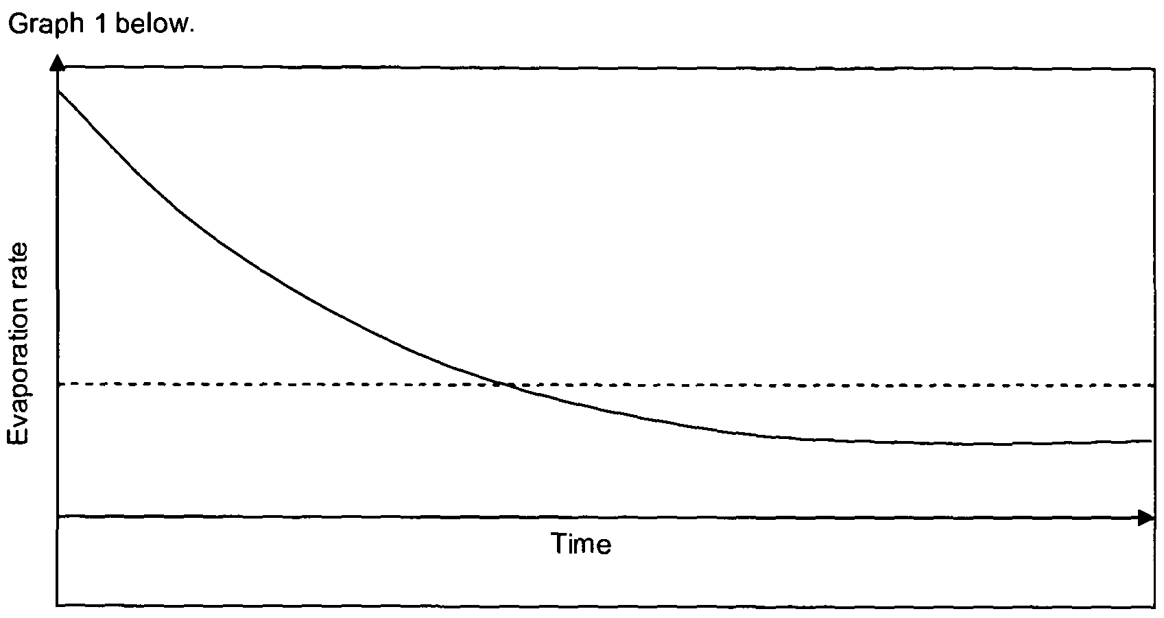
Graph 1
Eventually the emanation rate may reach equilibrium (dashed line) where the rate of evaporation of each individual component of the volatile liquid away from the membrane surface is equivalent to the rate of deposition due to diffusion and the device cannot maintain any further vacuum.
A further drawback with known passive volatile liquid emanators is that prolonged exposure of the volatile liquid to a wicking material, such as a membrane or the like, can cause fractionation over time due to various factors such as the wicking material having a limited porosity affecting liquid transfer rates/evaporation rates which , in turn, can change the character and/or intensity of the volatile liquid being emanated. Changes in character of emanated volatile liquids is particularly noticeable for fragrances wherein common wicking materials cause the 'high notes' of a fragrance to be evaporated when the wicking material is first exposed to the fragranced liquid, and the 'low notes' are evaporated thereafter which affects the user's experience.
Turning to drawbacks with known powered emanation devices, the effect of fractionation is particularly pronounced for powered emanation devices using a heater to effect emanation, such as a plug-in emanation device or the like. The phenomenon described above wherein changes in character for fragrances are noticeable as the 'high notes' of a fragrance are the first to be evaporated when the wicking material is first exposed to the fragranced liquid, and the 'low notes'
are evaporated thereafter which affects the user's experience is found to be particularly pronounced when a heater is used to drive the emanation of the fragrance.
Accordingly, it is an object of the present invention to provide a device that is capable of addressing the abovementioned performance drawbacks and other drawbacks that will be appreciated by a person skilled in the art.
Summary of Invention
According to a first aspect of the present invention there is provided therefore an emanation device for emanating a volatile liquid containing one or more active materials wherein the active material comprises at least one of: a fragrance; an insecticide; a fungicide; a pesticide; a sanitising material; and/or a pharmaceutical;
and wherein the emanation device comprises:
a housing;
a passive delivery mechanism ;
a powered emanation means;
wherein the housing is arranged to support the passive delivery mechanism in spatial arrangement over the emanation means; and
wherein the delivery mechanism comprises:
a volatile liquid reservoir;
one or more capillary tubes in fluid communication with the reservoir at one end thereof wherein said one or more capillary tubes are in non-valved fluid communication with the reservoir; and a nozzle located at the end of the or each capillary tube(s) remote from the reservoir wherein the or each nozzle is in non-valved fluid communication with the or each capillary tube(s).
In the context of the present invention "non-valved" should be understood as meaning that that component of the device has no mechanical features which enable it to regulate or adjust the flow of liquid therethrough.
In the context of the present invention "passive" should be understood as meaning that that the delivery mechanism is operable without a power source or some other means which drives the delivery of the volatile liquid to the emanation means; in other words the delivery mechanism of the present invention only requires gravity in order deliver volatile liquid to the emanation means.
According to a second aspect of the present invention there is provided therefore an emanation device comprising:
a housing;
a passive delivery mechanism;
a powered emanation means;
wherein the housing is arranged to support the passive delivery mechanism in spatial arrangement over the emanation means; and
wherein the delivery mechanism comprises:
a volatile liquid reservoir holding a volatile liquid containing one or more active materials wherein the active material comprises at least one of: a fragrance; an insecticide; a fungicide; a pesticide; a sanitising material; and/or a pharmaceutical;
one or more capillary tubes in fluid communication with the reservoir at one end thereof wherein said one or more capillary tubes are in non-valved fluid communication with the reservoir; and a nozzle located at the end of the or each capillary tube(s) remote from the reservoir wherein the or each nozzle is in non-valved fluid communication with the or each capillary tube(s).
According to a third aspect of the present invention there is provided therefore a passive delivery mechanism for an emanation device according to the first aspect of the present invention, wherein the delivery mechanism is connectable, preferably releaseably connectable, to a housing of the emanation device and wherein the passive delivery mechanism comprises:
a volatile liquid reservoir holding a volatile liquid containing one or more active materials wherein the active material comprises at least one of: a fragrance; an insecticide; a fungicide; a pesticide; a sanitising material; and/or a pharmaceutical;
one or more capillary tubes in fluid communication with the reservoir at one end thereof wherein said one or more capillary tubes are in non-valved fluid communication with the reservoir;
a nozzle located at the end of the or each capillary tube(s) remote from the reservoir wherein the or each nozzle is in non-valved fluid communication with the or each capillary tube(s).
According to a forth aspect of the present invention there is provided a method of providing a non-valved flow rate of volatile liquid between substantially 0.1 - 500//L/hr on to an emanation means, wherein the method comprises the steps of placing a device according to the second aspect of the present invention in a location where emanation of the volatile liquid is desired and causing the non-valved flow of liquid from the passive delivery mechanism toward the emanation means and activating said emanation means to emanate the volatile liquid into the surrounding environment.
The non-valved arrangement may provide a device that once the liquid is allowed to flow from the reservoir the liquid will flow substantially continuously from the reservoir into the capillary tube to the nozzle and in the form of droplets on to the emanation substrate at a non-valved flow rate of
between substantially 0.1 - 500 vL/hr, and preferably between substantially 20 - 40/yL/hr, and most preferably between substantially 26 - 34/yL/hr.
With a non-valved passive emanation device, it is critical to provide the device with a flow rate that is suited to ensure a peak emanation delivery rate from the emanation substrate. If the flow rate is too low the emanation rate will also be low and potentially produce a non-uniform emanation rate from the emanation substrate due to the substrate being generally dry or semi-dry when the liquid contacts the substrate with thus causing the substrate absorb and only slowly release the liquid as well as potentially exposing the components of the liquid to fractionation as the liquid is carried by wicking/capillary action along the substrate. Conversely if the flow rate is too high the emanation rate may be too high which in the case of a fragranced liquid could be overpowering for a user. A high flow rate also the risk of the liquid pooling on the emanation substrate as the substrate becomes saturated with the liquid , in the case of volatile liquids that can present dangers to the surface on which the device is located since volatile liquids may pose a potential health and/or fire hazard as well as a staining hazard to the surface supporting the device. The present inventors have advantageously found the aforementioned flow rate of 20 - 40/yL/hr to represent the peak flow rate to emanate the volatile liquid to ensure satisfactory emanation rate thereof and ensuring the uniform emanation of the liquid whilst substantially preventing any pooling of the liquid on the emanation substrate.
The mass of each droplet is preferably between substantially 0.1 - 500mg, and more preferably between substantially 0.5 - 70mg.
The inter-relationship of the various components of the delivery mechanism is critical in ensuring that the desired non-valved flow rate and droplet size is achieved.
The reservoir is preferably substantially completely enclosed to prevent the evaporation of volatile liquid therefrom. The reservoir is preferably provided with a vent hole that can be opened to permit the flow of volatile liquid from the reservoir without the build up of negative pressure or a vacuum in the headspace of the reservoir. The vent hole is preferably provided in a side wall or an upper cover of the reservoir above the max height of the volatile liquid retained therein to permit air to vent into the headspace of the reservoir above the volatile liquid . The vent hole is preferably provided with an area of between substantially 7.9x10"3 - 1 .9x103mm2, and even more preferably with an area of between substantially 0.8 - 3.1 mm2. The vent hole is preferably substantially cylindrical and provided with a diameter of between substantially 0.01 - 50mm, and even more preferably with a diameter of between substantially 1 - 2mm.
The vent hole may be covered by a removable seal member such that, once opened it shall remain open. Alternatively, the vent hole may be covered by a re-sealable sealing member which can be opened and re-sealed as desired by the user to, in effect, turn the emanation of volatile liquid from the device between a binary on and off position but without providing a user with the ability to select a position therebetween which could alter the non-valved flow rate.
The reservoir may be sized to retain a volume of volatile liquid between substantially 0.1 - 500ml, and preferably between substantially 10 - 40ml.
The reservoir may be shaped such that the volatile liquid head height therewithin is between substantially 0.1 - 100cm, and preferably between substantially 3 - 10cm; the liquid head height is defined within the context of the present invention as being the height of the liquid from the nozzle to the liquid-air surface in the reservoir.
The device and/or delivery mechanism may be provided with a mechanical boost means which is operable to increase the flow rate of the volatile liquid from the non-valved flow rate to an enhanced flow rate.
Preferably the mechanical boost means is in the form of an air pump connected to the reservoir which allows a user to pump air into the headspace of the reservoir to increase the air pressure thereof to at least temporarily increase the flow rate from the non-valved flow rate to the enhanced flow rate, once the user ceases further pumping the non-valved flow rate will resume once the air pressure in the head space equalises over a period of time.
Alternatively an auxiliary flow route for the volatile liquid may be provided, said auxiliary flow route being operable to being opened by a user to increase the flow rate to the enhanced flow rate before being closed and the flow rate being returned to the non-valved flow rate. The auxiliary flow route may be provided in the form of an aperture in the reservoir, possibly connected to a conduit, wherein the flow of volatile liquid therethrough is controlled by a valve that can be manipulated by a user. The auxiliary flow route would preferably be provided with a liquid exit orifice located substantially above the emanation substrate.
The auxiliary flow route may be connected to a auxiliary reservoir of volatile liquid which is adjacent to but not in liquid communication with the reservoir.
The enhanced flow rate may be between substantially 2 - 50 times greater than the non-valved flow rate, and preferably between substantially 2 - 5 times greater than the non-valved flow rate.
The reservoir may be provided in any shape, however, a substantially cylindrical shape is preferred. For substantially cylindrically shaped reservoirs they may be provided with a diameter of between substantially 1 - 50cm, but preferably with a diameter of between substantially 4 - 8cm, and may be provided with a depth of between substantially 0.1 - 100cm, but preferably with a depth of between substantially 0.5 - 2cm.
Preferably at least a portion of the reservoir is transparent to permit a user to see the level of volatile liquid held within, preferably substantially all of the reservoir is transparent.
Preferably the devices/delivery mechanisms according to the present invention are provided with a single capillary connected to the reservoir.
The or each capillary tube is preferably made of glass or plastic and may be substantially cylindrical although it could be provided in numerous other geometric shapes. The capillary tube(s) is preferably of a uniform shape and cross-section throughout its length. The capillary tube(s) may be provided with a length of between substantially 0.1 - 50cm, and preferably with a length of between substantially 3 - 10cm. In the most preferred embodiment the capillary tube(s) is/are substantially cylindrical and provided with an internal diameter of between substantially 1 - ΙΟΟΟμητι, and preferably with an internal diameter of between substantially 75 - 100/ m.
The capillary tube(s) may be provided with a filter to ensure that any contaminants in the volatile liquid do not inadvertently cause a blockage to liquid entering and moving along the capillary during use, thus, potentially affecting the flow rate.
The nozzle(s) is/are preferably provided with a substantially circular exit orifice having a diameter of between substantially 0.01 - 100mm, but preferably has a diameter of between substantially 0.4 - 2mm. The nozzle(s) may be provided with a cap to ensure that no volatile liquid is lost therefrom prior to use by a user.
The volatile liquid for use with the device/delivery mechanism of the present invention preferably possesses the at least one of, or more preferably two of, or most preferably al three of the following properties:
- viscosity between substantially 0.1 - 100cP, and preferably between substantially 1 - 5cP;
- density between substantially 0.1 - 10g/L, and preferably between substantially 0.8 - 1.1g/L;
- average surface tension between substantially 1 - 100mN/m, and preferably between substantially 1 - 50mN/m.
The emanation means is preferably provided in the form of a heater thermally connected to a heater plate which is operable to increase its temperature to accelerate the evaporation of the volatile liquid from the heater plate. Alternatively the heater plate could be provided in the form of an absorbent material such as a wick material which is capable of transporting the volatile liquid toward the heater to volatise the liquid from the absorbent material.
In a preferred embodiment of the present invention, the absorbent material is pre-dosed with the volatile liquid held in the reservoir. To maintain the level of pre-dosing of the absorbent material the absorbent material may be covered in a removable protective film to prevent or substantially prevent the emanation of the liquid therefrom until the film is removed by a user before use. Alternatively or additionally, the whole device may be sealed in a protective atmosphere to reduce or limit any natural evaporation of the pre-dosed volatile liquid from the absorbent material until a user removes the protective atmosphere immediately prior to use. Such a protective atmosphere may be provided in the form of a sealed packaging or the like. The pre-dosing of the absorbent material has been found to be particularly advantageous as it ensures that when the non-valved flow of liquid from the reservoir on to the absorbent material commences, emanation from the material is immediately affected whereas without pre-dosing the material will, for an initial period of time, mainly absorb the liquid before emanating the liquid into the surrounding environment.
Alternatively, the emanation means is provided in the form of a ultrasonic transducer element, such as a piezo-actuated emanator wherein the volatile liquid drops directly on to the piezo emanator or on to a plate connected to said piezo-actuated emanator and volatised therefrom once the emanator is activated.
The emanation means may be powered by mains-supplied electricity and/or be battery powered and/or be powered by solar cells located on the device, preferably the emanation means are battery powered however to afford greater portability over a device wherein the emanation means use mains-supplied electricity. Alternatively the device may be provided with a docking station which may be battery powered and/or mains electricity powered in order to provide a charge to batteries held within the device to power the emanation means such that the device may be removed from the docking station for improved portability.
The housing is preferably provided in the form of an open framework which is configured to suspend the reservoir such that the capillary and nozzle are held directly above a substantially central point of the emanation means. Whilst an open framework is preferred since a user will be able to monitor the progress of volatile liquid from the reservoir through the capillary tube and out
of the nozzle on to the emanation means, the framework may be totally or partially enclosed to improve the safe operation of the device by preventing a user from being able to interrupt the flow from the liquid from the nozzle to the emanation means.
The preferred volatile liquid used with the device/delivery mechanism/method of the present invention is fragranced liquid for use as an air freshener. The present invention has been found to be particularly advantageous compared with known emanation methods due to the nature of fragranced volatile liquids.
Brief Description of the Drawings
Embodiments of the invention will now be described, by way of example only, with reference to the following drawings in which:
Fig. 1 illustrates a side sectioned view of an emanation device;
Fig. 2 illustrates a perspective view of the emanation device; and
Fig. 3 illustrates a perspective view of a delivery mechanism for a passive emanation device. Description of an Embodiment
Figs. 1 & 2 illustrate an emanation device 1 which is generally arranged to have a housing 2 provided in the form of framework 3 supporting a delivery mechanism 12 which contains a quantity of volatile liquid 5. The delivery mechanism 12 is supported over an emanation means 6. The delivery mechanism 12 has a reservoir 4 which is provided in this embodiment with a single capillary tube 7 which extends from a substantially central portion of the reservoir 4 toward the emanation means 6. At the remote end of the capillary tube 7 is located a nozzle 8 from which, in use, volatile liquid will drop towards the emanation means 6.
Specifically the delivery mechanism 12 is a passive mechanism as it is not powered by any form of propulsion or motor or electricity etc, rather it simply relies on the force of gravity to be operable and provide a non-valved flow rate. The delivery mechanism 12 is, importantly, non- valved in that there are no mechanical features of the delivery mechanism which can be altered to reduce the non-valved flow rate of liquid from the reservoir 4 to the emanation means 6 once the liquid has been allowed to flow, thus ensuring that the device is operating at an optimum flow rate or not operating at all. The optimum flow rate (the non-valved flow rate) for this device is 0.1 - 500 yL/hr, and preferably between substantially 20 - 40/vL/hr, and most preferably between substantially 26 - 34/yL/hr. Between 26 - 34/yL/hr is the optimum flow rate and this is achieved whilst maintaining the mass of each droplet at between substantially 0.1 - 500mg, and but preferably between substantially 0.5 - 70mg. Clearly the inter-relationship of the various
components of the device 1 are critical in ensuring that this optimum flow rate and droplet mass is achieved.
As shown in Figs. 1 & 2 the reservoir 4 is substantially completely enclosed which acts to prevent evaporation of volatile liquid 5 therefrom. The reservoir 4 has a vent hole 9 that can be opened to permit the flow of volatile liquid 5 from the reservoir 4 without the build up of negative pressure or a vacuum in the headspace of the reservoir. The vent hole 9 is provided in the upper cover of the reservoir. The vent hole 9 is covered by a re-sealable sealing member 10 which operates via a screw thread mechanism to allow it to be brought into and out of sealing engagement with a upper surface of the vent hole 9.
The reservoir 4 may be sized to retain a volume of volatile liquid between substantially 0.1 - 500ml, but in Figs. 1 & 2 it is sized to retain between substantially 10 - 40ml. The volatile liquid head height therewith in may be between substantially 0.1 - 100cm , but is shown as being between substantially 5 - 12cm.
The reservoir 4 may be provided in any shape, however, Figs. 1 &2 show the reservoir 4 to be substantially cylindrical with a diameter of between substantially 4 - 8cm and a depth of between substantially 0.5 - 2cm.
The framework 3 is of an open configuration so that it does not obscure the reservoir 4 which is transparent, thus permitting a user to see the level of volatile liquid held within. The capillary tube 7 is also transparent which allows the user to monitor the progress of liquid therethrough on its journey toward the emanation substrate 6.
The capillary tube 7 is shown as being made of glass and having a substantially uniform cylindrical shape having an internal diameter of between substantially 75 - 100 vm and a length between substantially 3 - 10cm. The capillary tube 7 ends at its lowermost portion with the nozzle 8 which is shown as having an exit orifice between substantially 0.4 - 2mm. The nozzle is shown as being surrounded by a capillary housing 1 1 which provides additional safety for the operation of the device but ensuring that the potentially delicate capillary tube 7 and nozzle 8 can not be accidentally interfered with by a user during normal operation. Furthermore, the capillary housing 11 offers the nozzle 8 a degree of shielding from air currents surrounding which may affect the flow rate of volatile liquid droplets leaving the nozzle. Although not shown, the capillary housing 11 and/or the nozzle 8 may be provided with a cap to ensure that no volatile liquid is lost therefrom prior to use by a user.
The emanation means 6 is provided in the form of an ultrasonic transducer powered by a piezo- actuator. The transducer is powered by batteries (not shown) and is operable to actuate at routine intervals in order to cause the break up of the volatile liquid drops dropped thereon into small particles having enough kinetic energy to travel into the surrounding environement.
Fig. 3 shows the delivery mechanism 12 which consists of a reservoir 4 which holds a quantity of volatile liquid 5 covered by a cap of the like (not shown), the reservoir 4 having a capillary tube 7 terminating in a nozzle 8. The delivery mechanism 12 could be used as a refill wherein it is replaceable within the housing 2 once the reservoir 4 held therewithin has been exhausted.
Examples are now described which illustrate the interoperation of the various parameters required to produce a delivery mechanism having the peak flow rates called for in the devices of the present invention.
Example 1

Reservoir Depth 1.06 cm
(fragrance)*
Vent Hole Diameter 1 mm
Fragrance Viscosity 3.2 cP
Fragrance Density 0.89 g/L
Fragrance Surface Tension 26.8 mN/m
Flow Rate 26.7 uL/hr
Both devices from examples 1 & 2 were operated for a continuous period until the fragranced volatile liquid was exhausted and the delivery mechanism of both devices consistently produced the flow rates and drop weights described above.
All of the features disclosed in this specification (including any accompanying claims, abstract and drawings), and/or all of the steps of any method or process so disclosed, may be combined in any combination, except combinations where at least some of such features and/or steps are mutually exclusive.
Each feature disclosed in this specification (including any accompanying claims, abstract and drawings) may be replaced by alternative features serving the same, equivalent or similar purpose, unless expressly stated otherwise. Thus, unless expressly stated otherwise, each feature disclosed is one example only of a generic series of equivalent or similar features.
The invention is not restricted to the details of the foregoing embodiment(s). The invention extends to any novel one, or any novel combination, of the features disclosed in this specification (including any accompanying claims, abstract and drawings), or to any novel one, or any novel combination, of the steps of any method or process so disclosed.
Claims
1. An emanation device for emanating a volatile liquid containing one or more active materials wherein the active material comprises at least one of: a fragrance; an insecticide; a fungicide; a pesticide; a sanitising material; and/or a pharmaceutical;
and wherein the emanation device comprises:
a housing;
a passive delivery mechanism;
a powered emanation means;
wherein the housing is arranged to support the passive delivery mechanism in spatial arrangement over the emanation means; and
wherein the delivery mechanism comprises:
a volatile liquid reservoir;
one or more capillary tubes in fluid communication with the reservoir at one end thereof wherein said one or more capillary tubes are in non-valved fluid communication with the reservoir; and a nozzle located at the end of the or each capillary tube(s) remote from the reservoir wherein the or each nozzle is in non-valved fluid communication with the or each capillary tube(s).
2. A device according to claim 1 , wherein the device is configured to allow liquid on to the emanation means at a non-valved flow rate of between substantially 0.1 - 500 L/hr, and preferably between substantially 20 - 40/vL/hr, and most preferably between substantially 26 -
3. A device according to claim 1 or claim 2, wherein the device is configured to allow the mass of each liquid droplet to be between substantially 0.1 - 500mg, and preferably between substantially 0.5 - 70mg.
4. A device according to any preceding claim, wherein the reservoir is provided with a vent hole.
5. A device according to claim 4, wherein the vent hole is covered by a re-sealable sealing member which can be opened and re-sealed.
6. A device according to any preceding claim, wherein the reservoir is sized to retain a volume of volatile liquid between substantially 0.1 - 500ml, and preferably between substantially 10 - 40ml.
7. A device according to any preceding claim, wherein the reservoir is shaped such that the volatile liquid head height therewithin is between substantially 0.1 - 100cm, and preferably between substantially 3 - 10cm.
8. A device according to any preceding claim , wherein the reservoir is substantially cylindrically shaped and have a diameter of between substantially 1 - 50cm , but preferably between substantially 4 - 8cm, and have a depth of between substantially 0.1 - 100cm, but preferably between substantially 0.5 - 2cm.
9. A device according to any preceding claim , wherein a single capillary tube is provided.
10. A device according to any preceding claim, wherein the capillary tube(s) is/are provided with a length of between substantially 0.1 - 50cm, and preferably with a length of between substantially 3 - 10cm.
11. A device according to any preceding claim , wherein the capillary tube(s) is/are substantially cylindrical and provided with an internal diameter of between substantially 1 - 1000/ m, and preferably with an internal diameter of between substantially 75 - 100//m.
12. A device according to any preceding claim , wherein the nozzle(s) is/are provided with a substantially circular exit orifice having a diameter of between substantially 0.01 - 100mm, but preferably has a diameter of between substantially 0.4 - 2mm.
13. A device according to any preceding claim, wherein the emanation means is a heater.
14. A device according to any of claims 1 -12, wherein the emanation means is an ultrasonic transducer.
15. A device according to any preceding claim, wherein the housing is provided in the form of an open framework which is configured to suspend the reservoir such that the capillary and nozzle are held directly above a substantially central point of the emanation means.
16. A passive delivery mechanism for an emanation device according to any preceding claim, wherein the delivery mechanism is connectable, preferably releaseably connectable, to a housing of the emanation device and wherein the passive delivery mechanism comprises:
a volatile liquid reservoir holding a volatile liquid containing one or more active materials wherein the active material comprises at least one of: a fragrance; an insecticide; a fungicide; a pesticide; a sanitising material; and/or a pharmaceutical;
one or more capillary tubes in fluid communication with the reservoir at one end thereof wherein said one or more capillary tubes are in non-valved fluid communication with the reservoir;
a nozzle located at the end of the or each capillary tube(s) remote from the reservoir wherein the or each nozzle is in non-valved fluid communication with the or each capillary tube(s).
17. An emanation device comprising:
a housing;
a passive delivery mechanism ;
a powered emanation means;
wherein the housing is arranged to support the passive delivery mechanism in spatial arrangement over the emanation means; and
wherein the delivery mechanism comprises:
a volatile liquid reservoir holding a volatile liquid containing one or more active materials wherein the active material comprises at least one of: a fragrance; an insecticide; a fungicide; a pesticide; a sanitising material; and/or a pharmaceutical;
one or more capillary tubes in fluid communication with the reservoir at one end thereof wherein said one or more capillary tubes are in non-valved fluid communication with the reservoir; and a nozzle located at the end of the or each capillary tube(s) remote from the reservoir wherein the or each nozzle is in non-valved fluid communication with the or each capillary tube(s).
18. A mechanism or device according to either claim 16 or claim 17 respectively, wherein the volatile liquid possesses the at least one of, or more preferably two of, or most preferably all three of the following properties:
- viscosity between substantially 0.1 - 100cP, and preferably between substantially 1 - 5cP;
- density between substantially 0.1 - 10g/L, and preferably between substantially 0.8 - 1.1g/L;
- average surface tension between substantially 1 - 100mN/m, and preferably between substantially 1 - 50m N/m.
19. A method of providing a non-valved flow rate of volatile liquid between substantially 0.1 - 500/ L hr on to an emanation means, wherein the method comprises the steps of placing a device according to claim 17 in a location where emanation of the volatile liquid is desired and causing the non-valved flow of liquid from the passive delivery mechanism toward the emanation means and activating said emanation means to emanate the volatile liquid into the surrounding environment.
20. A passive emanation device substantially as described herein and with reference to the drawings.
Applications Claiming Priority (2)
| Application Number | Priority Date | Filing Date | Title |
|---|---|---|---|
| GB1010592.2A GB2481427A (en) | 2010-06-24 | 2010-06-24 | Emanation device comprising one or more capillary tubes |
| GB1010592.2 | 2010-06-24 |
Publications (1)
| Publication Number | Publication Date |
|---|---|
| WO2011161464A1 true WO2011161464A1 (en) | 2011-12-29 |
Family
ID=42582892
Family Applications (1)
| Application Number | Title | Priority Date | Filing Date |
|---|---|---|---|
| PCT/GB2011/051190 Ceased WO2011161464A1 (en) | 2010-06-24 | 2011-06-24 | Volatile liquid emanation device with capillary |
Country Status (2)
| Country | Link |
|---|---|
| GB (1) | GB2481427A (en) |
| WO (1) | WO2011161464A1 (en) |
Cited By (4)
| Publication number | Priority date | Publication date | Assignee | Title |
|---|---|---|---|---|
| EP2968636A4 (en) * | 2013-03-13 | 2016-12-28 | Univ King Abdullah Sci & Tech | METHOD AND APPARATUS FOR ATOMIZING AND SPRAYING A LIQUID |
| CN109452242A (en) * | 2018-12-04 | 2019-03-12 | 董亚伦 | Intelligent environment protection electronic mosquito killer |
| CN114126671A (en) * | 2018-06-18 | 2022-03-01 | 柯林普公司 | Removable assembly for diffusion device |
| TWI774014B (en) * | 2020-06-30 | 2022-08-11 | 福芯科技股份有限公司 | Anti-mite device with volatile liquid heater |
Families Citing this family (3)
| Publication number | Priority date | Publication date | Assignee | Title |
|---|---|---|---|---|
| GB201110698D0 (en) * | 2011-06-24 | 2011-08-10 | Reckitt & Colman Overseas | Devices and methods for emanatign liquids |
| CN105875556A (en) * | 2016-05-16 | 2016-08-24 | 河海大学 | Ultrasonic water-saving mist spray insecticidal lamp |
| EP3606843B1 (en) * | 2017-04-02 | 2026-04-22 | Biofeed Environmentally Friendly Pest Control Ltd. | A device for slow release of fluids in a uniform manner |
Citations (6)
| Publication number | Priority date | Publication date | Assignee | Title |
|---|---|---|---|---|
| DE4018020A1 (en) * | 1989-06-05 | 1990-12-06 | Shimizu Construction Co Ltd | SCENT DELIVERY DEVICE |
| GB2357973A (en) * | 2000-01-07 | 2001-07-11 | Reckitt & Colmann Prod Ltd | A vapour release device |
| WO2004094071A1 (en) * | 2003-04-22 | 2004-11-04 | E.I. Dupont De Nemours And Company | Liquid dispersion device |
| WO2006004902A1 (en) * | 2004-06-30 | 2006-01-12 | S. C. Johnson & Son, Inc. | Improved wick to reduce liquid flooding and control release rate |
| WO2007121997A2 (en) * | 2006-04-26 | 2007-11-01 | Boehringer Ingelheim Microparts Gmbh | Discharge device and method for evaporating a liquid and evaporator |
| WO2009142955A1 (en) * | 2008-05-20 | 2009-11-26 | The Procter & Gamble Company | Device for emitting volatile compositions while reducing surface deposition and improving scent noticeability |
Family Cites Families (5)
| Publication number | Priority date | Publication date | Assignee | Title |
|---|---|---|---|---|
| US20040261790A1 (en) * | 2003-06-30 | 2004-12-30 | Microlin, L.C. | Moving emanators |
| FR2797189A1 (en) * | 1999-08-02 | 2001-02-09 | Jean Pierre Lenfant | Perfume diffuser has variable output dosing pump delivering perfume to centrifugal fan with optional porous disc attached |
| US20070247555A1 (en) * | 2006-04-21 | 2007-10-25 | Diersing Steven L | Delivery system for dispensing volatile materials with high level of solids using an electromechanical transducer device |
| FR2924954B1 (en) * | 2007-12-17 | 2010-10-01 | Osmooze | METHOD FOR CONTROLLING A DEVICE FOR THE NEBULIZATION OF LIQUIDS INTO THE AIR |
| FR2937884A1 (en) * | 2008-11-05 | 2010-05-07 | Osmooze | PROCESS FOR FORMING EMULSION FROM NON-MISCIBLE LIQUIDS IN THEM AND APPLICATION TO LIQUID SUPPLY OF A NEBULIZATION DEVICE |
-
2010
- 2010-06-24 GB GB1010592.2A patent/GB2481427A/en not_active Withdrawn
-
2011
- 2011-06-24 WO PCT/GB2011/051190 patent/WO2011161464A1/en not_active Ceased
Patent Citations (6)
| Publication number | Priority date | Publication date | Assignee | Title |
|---|---|---|---|---|
| DE4018020A1 (en) * | 1989-06-05 | 1990-12-06 | Shimizu Construction Co Ltd | SCENT DELIVERY DEVICE |
| GB2357973A (en) * | 2000-01-07 | 2001-07-11 | Reckitt & Colmann Prod Ltd | A vapour release device |
| WO2004094071A1 (en) * | 2003-04-22 | 2004-11-04 | E.I. Dupont De Nemours And Company | Liquid dispersion device |
| WO2006004902A1 (en) * | 2004-06-30 | 2006-01-12 | S. C. Johnson & Son, Inc. | Improved wick to reduce liquid flooding and control release rate |
| WO2007121997A2 (en) * | 2006-04-26 | 2007-11-01 | Boehringer Ingelheim Microparts Gmbh | Discharge device and method for evaporating a liquid and evaporator |
| WO2009142955A1 (en) * | 2008-05-20 | 2009-11-26 | The Procter & Gamble Company | Device for emitting volatile compositions while reducing surface deposition and improving scent noticeability |
Cited By (7)
| Publication number | Priority date | Publication date | Assignee | Title |
|---|---|---|---|---|
| EP2968636A4 (en) * | 2013-03-13 | 2016-12-28 | Univ King Abdullah Sci & Tech | METHOD AND APPARATUS FOR ATOMIZING AND SPRAYING A LIQUID |
| CN114126671A (en) * | 2018-06-18 | 2022-03-01 | 柯林普公司 | Removable assembly for diffusion device |
| CN114126671B (en) * | 2018-06-18 | 2025-04-22 | 柯林普公司 | Removable components for diffusion devices |
| US12447486B2 (en) | 2018-06-18 | 2025-10-21 | Caelimp | Removable assembly for a diffusing apparatus |
| CN109452242A (en) * | 2018-12-04 | 2019-03-12 | 董亚伦 | Intelligent environment protection electronic mosquito killer |
| CN109452242B (en) * | 2018-12-04 | 2021-09-28 | 上海帮帮虫害防治服务有限公司 | Intelligent environment-friendly electronic mosquito killer |
| TWI774014B (en) * | 2020-06-30 | 2022-08-11 | 福芯科技股份有限公司 | Anti-mite device with volatile liquid heater |
Also Published As
| Publication number | Publication date |
|---|---|
| GB2481427A (en) | 2011-12-28 |
| GB201010592D0 (en) | 2010-08-11 |
Similar Documents
| Publication | Publication Date | Title |
|---|---|---|
| EP3122388B1 (en) | Volatile material dispenser and method of emitting a volatile material | |
| EP2185205B1 (en) | Passive dispenser of volatile material | |
| WO2011161464A1 (en) | Volatile liquid emanation device with capillary | |
| ES2491106T3 (en) | Devices and methods for improved distribution of volatile liquids | |
| KR100468116B1 (en) | Dual function dispenser | |
| US9457117B2 (en) | Emanator element for volatile liquids and devices incorporating same | |
| US9155813B2 (en) | Volatile material dispensing system and method of use | |
| ES2485900T3 (en) | Devices and methods for improved distribution of volatile liquids | |
| JP2009525118A (en) | System for delivering volatile substances | |
| US20140103136A1 (en) | Spill-resistant air freshener canister | |
| WO2011161462A1 (en) | Volatile liquid emanation device with capillary | |
| AU2012273679A1 (en) | Devices and methods for emanating liquids | |
| CA2840370A1 (en) | Devices and methods for emanating liquids | |
| CA2840292A1 (en) | Devices and methods for emanating liquids | |
| US20160346420A1 (en) | Fragrance and chemical dispensers and methods for using the same | |
| EP3117841A1 (en) | Autonomously powered vapour release device |
Legal Events
| Date | Code | Title | Description |
|---|---|---|---|
| 121 | Ep: the epo has been informed by wipo that ep was designated in this application |
Ref document number: 11729452 Country of ref document: EP Kind code of ref document: A1 |
|
| NENP | Non-entry into the national phase |
Ref country code: DE |
|
| 122 | Ep: pct application non-entry in european phase |
Ref document number: 11729452 Country of ref document: EP Kind code of ref document: A1 |