US2723077A - Continuous envelopes - Google Patents
Continuous envelopes Download PDFInfo
- Publication number
- US2723077A US2723077A US369583A US36958353A US2723077A US 2723077 A US2723077 A US 2723077A US 369583 A US369583 A US 369583A US 36958353 A US36958353 A US 36958353A US 2723077 A US2723077 A US 2723077A
- Authority
- US
- United States
- Prior art keywords
- envelopes
- sheet
- envelope
- flaps
- backing sheet
- Prior art date
- Legal status (The legal status is an assumption and is not a legal conclusion. Google has not performed a legal analysis and makes no representation as to the accuracy of the status listed.)
- Expired - Lifetime
Links
- 238000007789 sealing Methods 0.000 description 18
- 230000000153 supplemental effect Effects 0.000 description 8
- 238000010276 construction Methods 0.000 description 2
- 230000004048 modification Effects 0.000 description 1
- 238000012986 modification Methods 0.000 description 1
Images
Classifications
-
- B—PERFORMING OPERATIONS; TRANSPORTING
- B65—CONVEYING; PACKING; STORING; HANDLING THIN OR FILAMENTARY MATERIAL
- B65D—CONTAINERS FOR STORAGE OR TRANSPORT OF ARTICLES OR MATERIALS, e.g. BAGS, BARRELS, BOTTLES, BOXES, CANS, CARTONS, CRATES, DRUMS, JARS, TANKS, HOPPERS, FORWARDING CONTAINERS; ACCESSORIES, CLOSURES, OR FITTINGS THEREFOR; PACKAGING ELEMENTS; PACKAGES
- B65D27/00—Envelopes or like essentially-rectangular flexible containers for postal or other purposes having no structural provision for thickness of contents
- B65D27/10—Chains of interconnected envelopes
Definitions
- This invention relates to envelopes and more .particularly to-a series or assembly of envelopes so mounted on a ⁇ flexible member that they may be continuously advanced to voperative lposition by the flexible member in a lbusiness -machine for addressing, -printing or other operation thereon.
- Another feature of advantage of the invention is that the envelopes of the series are mounted closely adjacent each other on a continuous sheet of greater width than the length of the envelopes which may be at folded with two or more envelopes on each fold, the folding line between the front panel and sealing flap of each envelope being disposed in alignment with the folding lines of the package.
- the envelopes may be individually separated from the group and from the backing sheet after addressing or other operation in a business machine by tearing the envelopes along the perforations provided on the supplemental ila s.
- Fig. l is a plan view of several envelopes shown in position on their backing sheet;
- Fig. 2 is a side or edge view of a portion of Fig. 1, and
- Fig. 3 is a perspective view of a group of envelopes so mounted that they form a flat folded package.
- 'the invention may include the following principal parts: First, envelopes having ⁇ front and rear panels, a sealing flap and inturned sealing 4flaps ofxusual 0r standard form; second, outstanding supplemental 'flaps on the opposite ends of one o'f't'he envelope panels; third, a .line of perforations 'between the supplemental flaps and theirpanel; ⁇ and fourth, a backing strip 'to which the envelopes are attached by means of the .supplemental flaps, the backing strip being foldable'with its fold lines coinciding "with vthe fold lines 'of the sealingaps of spaced envelopes.
- each envelope 1G is l,provided with outstanding laps or 'extensions '20.
- ⁇ the yinturned Yflaps 16 -'for jforming the envelopes are extended from the front panel 12 and the outstanding il ps 20 extend from the rear ⁇ panel '14.
- This sheet 22 Secured to the outstanding flaps 20 is a backing sheet 22.
- This sheet 22, preferably of thin paper, as shown has spaced circular apertures 24 extending along itsv opposite edges to engage the teeth of feeding wheels of a business machine by means of which the sheet 22, with envelopes 10 attached thereto, may be advanced to successively position the envelopes individually for addressing, printing or other operation.
- the backing sheet as shown in Fig. 3 of the drawing is adapted to be flat or zig-zag folded to form a convenient package for shipping and handling.
- Each fold may have several envelopes 10 thereon with their panels closely adjacent each other.
- the major portion of the sealing ilap 18 of each envelope 10 is below the panels of the adjacent envelope 10 above or ahead of it so that the envelopes will feed easily through a business machine.
- the envelopes 10 are so mounted on the backing sheet 22 that the fold lines 26 of the sheet 22 to form the dat folded package are aligned with the fold lines 19 between the front panel 12 and sealing ap 18 of the spaced envelopes.
- the fold lines 26 of the sheet 22 to form the dat folded package are aligned with the fold lines 19 between the front panel 12 and sealing ap 18 of the spaced envelopes.
- a series of envelopes mounted on a single continuous backing sheet in adjacent parallel positions, aps forming extensions from opposite ends of one of the panels of said envelopes, lines of perforations between said panels and extensions, attaching means for each of said envelopes to said sheet provided on said extensions, said backing sheet extending laterally beyond said envelopes and being foldable, whereby an equal number of envelopes may be mounted on each fold.
- a series of envelopes having sealing flaps mounted on a single continuous backing sheet in adjacent parallel positions and with each sealing flap extending under an adjacent envelope, iaps forming extensionsv from opposite ends of one of the panels of said envelopes, lines of perforations between said panels and extensions, attaching means for each of said envelopes to said sheet provided on said extensions, said backing sheet extending laterally beyond said envelopes and being zig-zag foldable with envelopes on each fold, and the fold lines of said backing sheet being in alignment with the fold lines between the panels and sealing ilaps.
- a series of spaced envelopes each having a panel and sealing ap, a single continuous backing sheet therefor, and means to detachably attach said envelopes individually to said sheet closely adjacent each other and with the sealing flap of one envelope positioned below the panel of its adjacent envelope.
- a series of closely adjacent envelopes attached individually to a zig-Zag folded single continuous backing sheet, there being a plurality of envelopes on each fold thereof, each envelope having a panel and sealing ap, the fold lines of said sheet being in alignment with the fold line between an envelope panel and its sealing flap.
- a series of envelopes a single continuous backing sheet to which said envelopes are individually attached, iiaps forming lateral extensions of said envelopes, lines of perforations between said ilaps and envelopes, means on said ilaps for attaching said envelopes to said backing sheet, said backing sheet being zig-zag foldable and having an equal number of envelopes on each fold.
Landscapes
- Engineering & Computer Science (AREA)
- Mechanical Engineering (AREA)
- Making Paper Articles (AREA)
Description
N0 8, 1955 H. M. WHITMAN CONTINUOUS ENvELoPEs Filed July 22 FIGA OOO
rrfe
i OOO United States Patent hice 2,723,077 fatented Nov. 8, 1.955
`CONTINUOUS LENVELOPES Harlan tM. Whitman, West Hartford, Conn., :assigner to Curtis .1000, Incorporated, tHartford, Conn., .-a ycorporation offMinnesota Application July l22, '1953, lSerial No.'369,-583 7 Claims. (CL. 229-69) This invention relates to envelopes and more .particularly to-a series or assembly of envelopes so mounted on a `flexible member that they may be continuously advanced to voperative lposition by the flexible member in a lbusiness -machine for addressing, -printing or other operation thereon.
A primary object of "the present invention is to provide -a series of envelopes having their ,panels slightly spaced apart and with each sealing flap `below andretained by -the ypanel of 4an adjacent envelope, the envelopes each being attached to a backing sheet provided with feeding wheellperforations in ia ,manner to permit successively feeding vsaid envelopes "ndividually to an operative V:position in 'a business imachine ,A featureof importance of the invention is .that reach envelope, Jin addition to the usual `-gurnmed seal [forming flaps `at .the opposite ends of =one :of the panels, lby which the envelope is formed, has outstanding lsupplemental gllaps ror extensions on its fopposite end-s', `these supplementalaps having a line ofzperforationslbymeans of which they may be severed from the panel of which they form extensions, these extensions or flaps being attached along opposite sides of the backing sheet.
Another feature of advantage of the invention is that the envelopes of the series are mounted closely adjacent each other on a continuous sheet of greater width than the length of the envelopes which may be at folded with two or more envelopes on each fold, the folding line between the front panel and sealing flap of each envelope being disposed in alignment with the folding lines of the package.
And finally it is a feature of importance that the envelopes may be individually separated from the group and from the backing sheet after addressing or other operation in a business machine by tearing the envelopes along the perforations provided on the supplemental ila s.
IVith the above and other objects in View the invention may include the features of construction and operation set forth in the following specification and illustrated in the accompanying drawing.
In the accompanying drawing annexed hereto and forming a part of this 'specicatiom I have shown the invention embodied in a seriesl of standard business mailing envelopes but it will be understood that the invention can be otherwise embodied and that the drawing is not to be construed as dening or limiting the scope of the invention, the claims appended to this specification being relied upon for that purpose.
In the drawing:
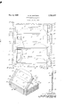
Fig. l is a plan view of several envelopes shown in position on their backing sheet;
Fig. 2 is a side or edge view of a portion of Fig. 1, and
Fig. 3 is a perspective view of a group of envelopes so mounted that they form a flat folded package.
In the above mentioned drawing, there has been shown I2 but one ,embodiment .of 'the invention which is 110W deemed preferable, but it is to be understood that changes and :modifications may be made within the scope -ofthe appended claims without departing from the Vspirit of the invention.
Briefly, .and in its preferred aspect, 'the invention may include the following principal parts: First, envelopes having `front and rear panels, a sealing flap and inturned sealing 4flaps ofxusual 0r standard form; second, outstanding supplemental 'flaps on the opposite ends of one o'f't'he envelope panels; third, a .line of perforations 'between the supplemental flaps and theirpanel; `and fourth, a backing strip 'to which the envelopes are attached by means of the .supplemental flaps, the backing strip being foldable'with its fold lines coinciding "with vthe fold lines 'of the sealingaps of spaced envelopes.
This vapplication is a continuation inpart of my copending application 'Ser. No. 316,586 tiled 'October 24, 19'52.
AReferring more in detail to the figures of the drawing, it will be vseen that 'the envelopes 10 are of the same shape and construction as shown in the above mentioned application. The front and rear panels ,12 and 14 are secured together along their opposite ends :by inturned `'flaps L16 in the Vusual .manner and `have sealing flaps u18 of any conventional form. 'In .addition to the inturned flaps '16 each envelope 1G is l,provided with outstanding laps or 'extensions '20. These flaps `2'0 .may extend `'from lopposite ends of Aeither the front or rear panel 1'2 4or 1'4. Preferably :for -business mailing -envelopes'and as shown in the drawing, `the yinturned Yflaps 16 -'for jforming the envelopes are extended from the front panel 12 and the outstanding il ps 20 extend from the rear `panel '14. Along 'the inner edges of .the outstanding x'flaps 20 'are 'lines' of perforations 21 by means of which these flaps may be readily severed from the envelopes.
Secured to the outstanding flaps 20 is a backing sheet 22. This sheet 22, preferably of thin paper, as shown has spaced circular apertures 24 extending along itsv opposite edges to engage the teeth of feeding wheels of a business machine by means of which the sheet 22, with envelopes 10 attached thereto, may be advanced to successively position the envelopes individually for addressing, printing or other operation.
The backing sheet as shown in Fig. 3 of the drawing is adapted to be flat or zig-zag folded to form a convenient package for shipping and handling. Each fold may have several envelopes 10 thereon with their panels closely adjacent each other. The major portion of the sealing ilap 18 of each envelope 10 is below the panels of the adjacent envelope 10 above or ahead of it so that the envelopes will feed easily through a business machine. Also the envelopes 10 are so mounted on the backing sheet 22 that the fold lines 26 of the sheet 22 to form the dat folded package are aligned with the fold lines 19 between the front panel 12 and sealing ap 18 of the spaced envelopes. In the embodiment of the package illustrated there are two envelopes on each fold of the sheet 22. It will be understood that with different sizes of envelopes three or more may be mounted on each fold of the sheet 22. In each case, however, the folds 26 of the sheet 22 will coincide with the fold lines 19 between the envelope panel and sealing ilap 18. At one end of a fold of the sheet 22 the ap 18 will be folded forwarded and at the opposite end of the fold the sealing flap 18 will be folded rear- Wardly.
To remove the envelopes 10 from the sheet 22 it is only necessary to tear the envelope along the line of perforation 21 between the panel on which the supplemental flaps 20 are formed. This may conveniently be Lb done in the embodiment of the invention illustrated in the drawing by placing the hand below the panel 14 of the envelope being removed and above the sealing flap 18 of the adjacent envelope.
By means of the overlapping of the panels 1.2 and 14 of one envelope with the sealing ilap 18 of an adjacent envelope, the movement of the envelopes continuously by feeding wheels (not shown) engaging perforations 24 is facilitated.
l claim as my invention:
l. A series of envelopes mounted on a single continuous backing sheet in adjacent parallel positions, aps forming extensions from opposite ends of one of the panels of said envelopes, lines of perforations between said panels and extensions, attaching means for each of said envelopes to said sheet provided on said extensions, said backing sheet extending laterally beyond said envelopes and being foldable, whereby an equal number of envelopes may be mounted on each fold.
2. A series of envelopes having sealing flaps mounted on a single continuous backing sheet in adjacent parallel positions and with each sealing flap extending under an adjacent envelope, iaps forming extensionsv from opposite ends of one of the panels of said envelopes, lines of perforations between said panels and extensions, attaching means for each of said envelopes to said sheet provided on said extensions, said backing sheet extending laterally beyond said envelopes and being zig-zag foldable with envelopes on each fold, and the fold lines of said backing sheet being in alignment with the fold lines between the panels and sealing ilaps.
3. A series of spaced envelopes, each having a panel and sealing ap, a single continuous backing sheet therefor, and means to detachably attach said envelopes individually to said sheet closely adjacent each other and with the sealing flap of one envelope positioned below the panel of its adjacent envelope.
4. A series of similar envelopes spaced closely adjacent and in parallel relation to each other, a single continuous backing sheet therefor, supplemental iiaps at opposite ends of said envelopes for attaching said envelopes individually to said sheet, said sheet extending laterally beyond said envelopes and aps and having feeding holes along opposite sides thereof.
5. A Series of similar envelopes spaced closely adjacent and in parallel relation to each other, a single continuous backing sheet therefor extending laterally be-l yond said envelopes, supplemental flaps on said envelopes for attaching said envelopes individually to said backing sheet, feeding means on said backing sheet to individually feed said envelopes successively to a business machine, and lines of perforations between said supplemental flaps and said sheet to facilitate removal of said envelopes individually from said sheet.
6. A series of closely adjacent envelopes attached individually to a zig-Zag folded single continuous backing sheet, there being a plurality of envelopes on each fold thereof, each envelope having a panel and sealing ap, the fold lines of said sheet being in alignment with the fold line between an envelope panel and its sealing flap.
7. A series of envelopes, a single continuous backing sheet to which said envelopes are individually attached, iiaps forming lateral extensions of said envelopes, lines of perforations between said ilaps and envelopes, means on said ilaps for attaching said envelopes to said backing sheet, said backing sheet being zig-zag foldable and having an equal number of envelopes on each fold.
UNITED STATES PATENTS References Cited in the le of this patent
Priority Applications (1)
| Application Number | Priority Date | Filing Date | Title |
|---|---|---|---|
| US369583A US2723077A (en) | 1953-07-22 | 1953-07-22 | Continuous envelopes |
Applications Claiming Priority (1)
| Application Number | Priority Date | Filing Date | Title |
|---|---|---|---|
| US369583A US2723077A (en) | 1953-07-22 | 1953-07-22 | Continuous envelopes |
Publications (1)
| Publication Number | Publication Date |
|---|---|
| US2723077A true US2723077A (en) | 1955-11-08 |
Family
ID=23456051
Family Applications (1)
| Application Number | Title | Priority Date | Filing Date |
|---|---|---|---|
| US369583A Expired - Lifetime US2723077A (en) | 1953-07-22 | 1953-07-22 | Continuous envelopes |
Country Status (1)
| Country | Link |
|---|---|
| US (1) | US2723077A (en) |
Cited By (17)
| Publication number | Priority date | Publication date | Assignee | Title |
|---|---|---|---|---|
| US2824686A (en) * | 1955-03-09 | 1958-02-25 | William S Hamilton | Continuous envelope |
| US2824685A (en) * | 1954-02-11 | 1958-02-25 | Uarco Inc | Assembly of series-connected envelopes and method of making same |
| US2961136A (en) * | 1956-12-10 | 1960-11-22 | Curtiss 1000 Inc | Continuous envelope stripper |
| US3161347A (en) * | 1962-08-20 | 1964-12-15 | Gilbert H Hannon | Bag package |
| US3208663A (en) * | 1964-06-16 | 1965-09-28 | Albert H Johnson | Continuous series of envelopes |
| US3208662A (en) * | 1963-12-05 | 1965-09-28 | Albert H Johnson | Continuous series of envelopes |
| US3214083A (en) * | 1963-12-17 | 1965-10-26 | John H Jory | Article transportation means for printing apparatus |
| US3237970A (en) * | 1964-01-28 | 1966-03-01 | Curtis 1000 Inc | Mailing envelopes |
| US3273784A (en) * | 1963-05-08 | 1966-09-20 | Moore Business Forms Inc | Envelope assemblies |
| US3294423A (en) * | 1965-06-25 | 1966-12-27 | Curtis 1000 Inc | Continuous envelopes |
| US3332604A (en) * | 1966-03-10 | 1967-07-25 | Curtis 1000 Inc | Continuous envelope |
| US3618756A (en) * | 1969-09-26 | 1971-11-09 | Wyomissing Corp | Article-holding tabs for peel-open packages |
| US3758025A (en) * | 1971-07-30 | 1973-09-11 | Pak Well Corp | Continuous web and affixed envelopes with selective spacing |
| US3863835A (en) * | 1972-09-18 | 1975-02-04 | Us Envelope Co | Letter packages |
| US3910413A (en) * | 1973-03-21 | 1975-10-07 | Gao Ges Automation Org | Transparent package |
| US4084741A (en) * | 1977-07-29 | 1978-04-18 | Wallace Business Forms, Inc. | Continuous form multiple ply envelope assembly |
| US4091987A (en) * | 1976-09-24 | 1978-05-30 | Web Graphics, Inc. | Carrier sheet business form assembly |
Citations (6)
| Publication number | Priority date | Publication date | Assignee | Title |
|---|---|---|---|---|
| US1157432A (en) * | 1914-03-05 | 1915-10-19 | Ray R Simpson | Combined envelop, shipping-tag, and index-card. |
| US1434097A (en) * | 1922-10-31 | Envelope | ||
| US1453616A (en) * | 1921-11-15 | 1923-05-01 | Benenato Stella | Envelope |
| US1710603A (en) * | 1924-06-18 | 1929-04-23 | Benenato Stella | Mailable matter of envelopes |
| US2013844A (en) * | 1934-06-04 | 1935-09-10 | John Q Sherman | Continuous feed envelope assembly |
| US2332638A (en) * | 1941-07-15 | 1943-10-26 | Us Envelope Co | Assembly of series-connected envelopes |
-
1953
- 1953-07-22 US US369583A patent/US2723077A/en not_active Expired - Lifetime
Patent Citations (6)
| Publication number | Priority date | Publication date | Assignee | Title |
|---|---|---|---|---|
| US1434097A (en) * | 1922-10-31 | Envelope | ||
| US1157432A (en) * | 1914-03-05 | 1915-10-19 | Ray R Simpson | Combined envelop, shipping-tag, and index-card. |
| US1453616A (en) * | 1921-11-15 | 1923-05-01 | Benenato Stella | Envelope |
| US1710603A (en) * | 1924-06-18 | 1929-04-23 | Benenato Stella | Mailable matter of envelopes |
| US2013844A (en) * | 1934-06-04 | 1935-09-10 | John Q Sherman | Continuous feed envelope assembly |
| US2332638A (en) * | 1941-07-15 | 1943-10-26 | Us Envelope Co | Assembly of series-connected envelopes |
Cited By (17)
| Publication number | Priority date | Publication date | Assignee | Title |
|---|---|---|---|---|
| US2824685A (en) * | 1954-02-11 | 1958-02-25 | Uarco Inc | Assembly of series-connected envelopes and method of making same |
| US2824686A (en) * | 1955-03-09 | 1958-02-25 | William S Hamilton | Continuous envelope |
| US2961136A (en) * | 1956-12-10 | 1960-11-22 | Curtiss 1000 Inc | Continuous envelope stripper |
| US3161347A (en) * | 1962-08-20 | 1964-12-15 | Gilbert H Hannon | Bag package |
| US3273784A (en) * | 1963-05-08 | 1966-09-20 | Moore Business Forms Inc | Envelope assemblies |
| US3208662A (en) * | 1963-12-05 | 1965-09-28 | Albert H Johnson | Continuous series of envelopes |
| US3214083A (en) * | 1963-12-17 | 1965-10-26 | John H Jory | Article transportation means for printing apparatus |
| US3237970A (en) * | 1964-01-28 | 1966-03-01 | Curtis 1000 Inc | Mailing envelopes |
| US3208663A (en) * | 1964-06-16 | 1965-09-28 | Albert H Johnson | Continuous series of envelopes |
| US3294423A (en) * | 1965-06-25 | 1966-12-27 | Curtis 1000 Inc | Continuous envelopes |
| US3332604A (en) * | 1966-03-10 | 1967-07-25 | Curtis 1000 Inc | Continuous envelope |
| US3618756A (en) * | 1969-09-26 | 1971-11-09 | Wyomissing Corp | Article-holding tabs for peel-open packages |
| US3758025A (en) * | 1971-07-30 | 1973-09-11 | Pak Well Corp | Continuous web and affixed envelopes with selective spacing |
| US3863835A (en) * | 1972-09-18 | 1975-02-04 | Us Envelope Co | Letter packages |
| US3910413A (en) * | 1973-03-21 | 1975-10-07 | Gao Ges Automation Org | Transparent package |
| US4091987A (en) * | 1976-09-24 | 1978-05-30 | Web Graphics, Inc. | Carrier sheet business form assembly |
| US4084741A (en) * | 1977-07-29 | 1978-04-18 | Wallace Business Forms, Inc. | Continuous form multiple ply envelope assembly |
Similar Documents
| Publication | Publication Date | Title |
|---|---|---|
| US2723077A (en) | Continuous envelopes | |
| US3554438A (en) | Correspondence assembly | |
| US3099381A (en) | Extra panel cartons | |
| US3312385A (en) | Envelope assembly | |
| US3863835A (en) | Letter packages | |
| US2317335A (en) | Envelope | |
| US2887326A (en) | Interleaved check and envelope inserts for check books | |
| US4586611A (en) | Business mailer | |
| US3356286A (en) | Envelope | |
| US3273784A (en) | Envelope assemblies | |
| US3542191A (en) | Matchbook-type package | |
| US2723076A (en) | Mailing envelopes | |
| US3339828A (en) | Individual envelope unit for use in tabulating and similar machines | |
| US3270949A (en) | Mailing piece | |
| US1558305A (en) | Envelope and carton | |
| US2330457A (en) | Stationery package | |
| US892179A (en) | Cigar-case. | |
| US2549199A (en) | Combination envelope and letter paper | |
| US722038A (en) | Envelop. | |
| US2189273A (en) | Envelope | |
| US2316757A (en) | Mailing piece | |
| US3214083A (en) | Article transportation means for printing apparatus | |
| US3458034A (en) | Letter pack | |
| US2175508A (en) | Envelope | |
| US2413649A (en) | Pay statement and envelope assembly |