US243924A - John f - Google Patents
John f Download PDFInfo
- Publication number
- US243924A US243924A US243924DA US243924A US 243924 A US243924 A US 243924A US 243924D A US243924D A US 243924DA US 243924 A US243924 A US 243924A
- Authority
- US
- United States
- Prior art keywords
- wire
- lamp
- lips
- support
- ring
- Prior art date
- Legal status (The legal status is an assumption and is not a legal conclusion. Google has not performed a legal analysis and makes no representation as to the accuracy of the status listed.)
- Expired - Lifetime
Links
- 238000010276 construction Methods 0.000 description 2
- 239000002184 metal Substances 0.000 description 2
- 238000005476 soldering Methods 0.000 description 2
- 239000011521 glass Substances 0.000 description 1
- 238000004519 manufacturing process Methods 0.000 description 1
- 230000000284 resting effect Effects 0.000 description 1
Images
Classifications
-
- F—MECHANICAL ENGINEERING; LIGHTING; HEATING; WEAPONS; BLASTING
- F21—LIGHTING
- F21V—FUNCTIONAL FEATURES OR DETAILS OF LIGHTING DEVICES OR SYSTEMS THEREOF; STRUCTURAL COMBINATIONS OF LIGHTING DEVICES WITH OTHER ARTICLES, NOT OTHERWISE PROVIDED FOR
- F21V17/00—Fastening of component parts of lighting devices, e.g. shades, globes, refractors, reflectors, filters, screens, grids or protective cages
Definitions
- My invention relates to that class of lamps ,known as wall or side lamps, having glass founts, and has for its object the production of a strong, durable, and cheap lamp.
- My invention consists in the support of the zo lamp-fount by means of a ring of wire bentin such manner as to furnish a means of attaching it firmly to the back or wall plate, and also in the manner of attaching the said wire support to the back or wall plate.
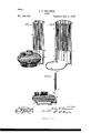
- Figure l shows a perspective view of the device with the lamp-fount resting in its support.
- Fig. 2 shows the same view of the device with the lamp-fount removed to show the form of the supportingring upon which it rests;
- Fig. 3 is a vertical central section of Fig. l, broken oft' just below the top of the reflector.
- A represents the back or wall plate, having the lips D D upon each of its vertical sides, which lips, above the point marked E, overlap the edges -of the reflector F, and below the 4o point marked E iuclose the vertical portion of the wire lamp-support C, in which the lampfount B is placed.
- the wire lamp-support C is outwardly bent'at G from its circular form, and at K the two ends, of equal length, are
- the reiiector F is supported vertically by the ends of the wire inclosed within the lips D D being slid within the lips from the top, and it may be readily removed by withdrawing it in the same direction.
- This construction may be varied by making the lamp-supportan entire ring, joined by soldering at its meeting ends, and two short wires, bent at a right angle, being soldered to the opposite sides of thering.
- the vertical portion of the short wires may be passed within thelips D D and secured, as described. I prefer the construction shown in the drawings, however, as being stronger, simpler, and cheaper.
Landscapes
- Engineering & Computer Science (AREA)
- General Engineering & Computer Science (AREA)
- Fastening Of Light Sources Or Lamp Holders (AREA)
Description
(Model.)
J. P. KRAMER. LAMP.
. Patented July 5, 1881.
lpmllllnml UNITED STATES PATENT OEEIcE.
JOHN F. KRAMER, OF NEW YORK, N. Y.
LAMP.
SPECIFICATION forming part of Letters Patent No. 243,924, dated July 5, 1881.
Application med May 4, 1881. (Model.)
To all whom it may concern Be it known that I, JOHN F. KRAMER, a citizen of the United States, residing at New York, in the county of New York and State of New York, have invented certain new and useful Improvements in Lamps; and I do hereby declare the following to be a full, clear, and exact description of the invention, such as will enable others skilled in the art to which it Io appertains to make and use the same, reference being had to the accompanying drawings, and to letters or Iigures ot' reference marked thereon, which form a part of ithis specification.
My invention relates to that class of lamps ,known as wall or side lamps, having glass founts, and has for its object the production of a strong, durable, and cheap lamp.
My invention consists in the support of the zo lamp-fount by means of a ring of wire bentin such manner as to furnish a means of attaching it firmly to the back or wall plate, and also in the manner of attaching the said wire support to the back or wall plate.
2 5 In the annexed drawings, forming part of this specification, Figure l shows a perspective view of the device with the lamp-fount resting in its support. Fig. 2 shows the same view of the device with the lamp-fount removed to show the form of the supportingring upon which it rests; and Fig. 3 is a vertical central section of Fig. l, broken oft' just below the top of the reflector.
Similar letters of reference denote correspending parts in each of the figures.
A represents the back or wall plate, having the lips D D upon each of its vertical sides, which lips, above the point marked E, overlap the edges -of the reflector F, and below the 4o point marked E iuclose the vertical portion of the wire lamp-support C, in which the lampfount B is placed. The wire lamp-support C is outwardly bent'at G from its circular form, and at K the two ends, of equal length, are
bent at a right angle upward from the plane of the ring.
H indicates where the lip D is shown turned down over the vertical portion of the wire.
In making my lamp-support I Iirst eut a 5o piece of sheet metal of the proper size, and having punched a hole at the upper end of the sheet, to pass over the nail from which it may be suspended, I turn up the lip D on each of its vertical sides to receive the reflector, and
also to receive the vertical ends of the wire.
I form the ring in which the lamp rests by taking a piece of metal wire or rod of the proper size and length and bend it from the center of its length into a circular form of a diameter sufiicient to permit the bottom of the lamp-fount to pass through itreadily. Having bent the wire to a circular form to about two-thirds of an entire circle, I then bend the wire outwardly, as shown at G in the drawings, and leaving from this point enough of the wire to give sufficient projection from the back, so that the lamp-fount may pass in to its place without coming in contact with the back. I bend the ends ot' the wire upward from the point K at right angles to the plane of the ring.
To unite the back and the wire ring l place the vertical extensions of the ring within the lips D D, extending them up equally on each side to the point E, and I then close the lips D D over them, as may be seen at H in Fig. 2, and I further secure them by soldering.
The reiiector F is supported vertically by the ends of the wire inclosed within the lips D D being slid within the lips from the top, and it may be readily removed by withdrawing it in the same direction.
This construction may be varied by making the lamp-supportan entire ring, joined by soldering at its meeting ends, and two short wires, bent at a right angle, being soldered to the opposite sides of thering. The vertical portion of the short wires may be passed within thelips D D and secured, as described. I prefer the construction shown in the drawings, however, as being stronger, simpler, and cheaper.
Having thus described my invention, what I claim, and desire to secure by Letters Patent, Is-
1. The combination, with the back A, of the wire lampsupport C, having the bends at G and K, as and forl the'purpose set forth.
2. The combination of the bent-wire larnp support O with the back A, having lips D D and reliector F, substantially as described.
3. The combination of the wire support O, back A, having lips D D, and reiiector F, with the lamp-forint B.
In testimony whereof I have aflixed my sg nature in presence of two witnesses.
JOHN F. KRAMER.
Witnesses:
R. G. HANEORD, DOUGLAS H. SCHNEIDER.
Publications (1)
| Publication Number | Publication Date |
|---|---|
| US243924A true US243924A (en) | 1881-07-05 |
Family
ID=2313253
Family Applications (1)
| Application Number | Title | Priority Date | Filing Date |
|---|---|---|---|
| US243924D Expired - Lifetime US243924A (en) | John f |
Country Status (1)
| Country | Link |
|---|---|
| US (1) | US243924A (en) |
Cited By (1)
| Publication number | Priority date | Publication date | Assignee | Title |
|---|---|---|---|---|
| US2568266A (en) * | 1950-06-12 | 1951-09-18 | Charles D Arnold | Container holder |
-
0
- US US243924D patent/US243924A/en not_active Expired - Lifetime
Cited By (1)
| Publication number | Priority date | Publication date | Assignee | Title |
|---|---|---|---|---|
| US2568266A (en) * | 1950-06-12 | 1951-09-18 | Charles D Arnold | Container holder |
Similar Documents
| Publication | Publication Date | Title |
|---|---|---|
| US243924A (en) | John f | |
| US613188A (en) | Lader | |
| US947596A (en) | Detachable lantern-reflector. | |
| US539199A (en) | Candlestick | |
| US242999A (en) | Reflector for suspended lamps | |
| US141162A (en) | Improvement in lanterns | |
| US241649A (en) | Eely s | |
| US141252A (en) | Improvement in shade-holders | |
| US473149A (en) | Candlestick | |
| US566255A (en) | Lamp-shade holder | |
| US297481A (en) | Reflector-holder for lamps | |
| US776249A (en) | Lamp-shade. | |
| US349763A (en) | John henry stone | |
| US363916A (en) | Lamp-shade support | |
| US609822A (en) | Combined bracket and stand for lamps | |
| US167187A (en) | Improvement in reflectors | |
| US442172A (en) | Burner-fastening for lamps and lanterns | |
| US182453A (en) | Improvement in lanterns | |
| US984944A (en) | Lamp-chimney holder. | |
| US340965A (en) | Egbert e | |
| US247307A (en) | chappel | |
| US529105A (en) | Reflector and shade for lamps | |
| US603417A (en) | James h | |
| US93535A (en) | Improvement in lanterns | |
| US520042A (en) | Necticut |