TWI838818B - Slot antenna structure and electronic device - Google Patents
Slot antenna structure and electronic device Download PDFInfo
- Publication number
- TWI838818B TWI838818B TW111129879A TW111129879A TWI838818B TW I838818 B TWI838818 B TW I838818B TW 111129879 A TW111129879 A TW 111129879A TW 111129879 A TW111129879 A TW 111129879A TW I838818 B TWI838818 B TW I838818B
- Authority
- TW
- Taiwan
- Prior art keywords
- slot
- length
- equal
- antenna structure
- ghz
- Prior art date
Links
- 239000002184 metal Substances 0.000 claims description 25
- 230000005540 biological transmission Effects 0.000 description 16
- 238000010586 diagram Methods 0.000 description 8
- 238000005452 bending Methods 0.000 description 1
- 230000004048 modification Effects 0.000 description 1
- 238000012986 modification Methods 0.000 description 1
- 230000004936 stimulating effect Effects 0.000 description 1
Images


Classifications
-
- H—ELECTRICITY
- H01—ELECTRIC ELEMENTS
- H01Q—ANTENNAS, i.e. RADIO AERIALS
- H01Q13/00—Waveguide horns or mouths; Slot antennas; Leaky-waveguide antennas; Equivalent structures causing radiation along the transmission path of a guided wave
- H01Q13/10—Resonant slot antennas
-
- H—ELECTRICITY
- H01—ELECTRIC ELEMENTS
- H01Q—ANTENNAS, i.e. RADIO AERIALS
- H01Q1/00—Details of, or arrangements associated with, antennas
- H01Q1/12—Supports; Mounting means
- H01Q1/22—Supports; Mounting means by structural association with other equipment or articles
- H01Q1/2258—Supports; Mounting means by structural association with other equipment or articles used with computer equipment
- H01Q1/2266—Supports; Mounting means by structural association with other equipment or articles used with computer equipment disposed inside the computer
-
- H—ELECTRICITY
- H01—ELECTRIC ELEMENTS
- H01Q—ANTENNAS, i.e. RADIO AERIALS
- H01Q21/00—Antenna arrays or systems
- H01Q21/30—Combinations of separate antenna units operating in different wavebands and connected to a common feeder system
-
- H—ELECTRICITY
- H01—ELECTRIC ELEMENTS
- H01Q—ANTENNAS, i.e. RADIO AERIALS
- H01Q5/00—Arrangements for simultaneous operation of antennas on two or more different wavebands, e.g. dual-band or multi-band arrangements
- H01Q5/50—Feeding or matching arrangements for broad-band or multi-band operation
Landscapes
- Engineering & Computer Science (AREA)
- Computer Hardware Design (AREA)
- General Engineering & Computer Science (AREA)
- Waveguide Aerials (AREA)
- Details Of Aerials (AREA)
- Support Of Aerials (AREA)
Abstract
Description
本發明係關於一種天線結構及電子裝置,特別是關於一種槽孔天線結構及電子裝置。The present invention relates to an antenna structure and an electronic device, and in particular to a slot antenna structure and an electronic device.
隨著無線傳輸需求的增加,一般筆記型電腦或其他行動裝置皆須具備天線以進行無線傳送及接收資料的功能。然而,隨著行動裝置的發展趨勢走向輕薄化,行動裝置中所使用的天線元件的體積亦須縮減。With the increasing demand for wireless transmission, general laptops or other mobile devices must be equipped with antennas to perform wireless data transmission and reception. However, as mobile devices are becoming thinner and lighter, the size of antenna components used in mobile devices must also be reduced.
有鑑於此,開發一種可提高天線頻寬的同時將體積縮小之槽孔天線結構及電子裝置,遂成相關業者值得研發之目標。In view of this, developing a slot antenna structure and electronic device that can increase the antenna bandwidth while reducing the size has become a goal worth developing for related industries.
因此,本發明之目的在於提供一種槽孔天線,其將長度相異的第一槽孔、第二槽孔及第三槽孔設置於一直線,以實現雙頻段的資料傳送及接收。Therefore, the object of the present invention is to provide a slot antenna, which arranges a first slot, a second slot and a third slot of different lengths in a straight line to achieve dual-band data transmission and reception.
依據本發明的結構態樣之一實施方式提供一種槽孔天線結構,包含一天線單元及一金屬件。金屬件電性連接天線單元,並包含一第一槽孔、一第二槽孔及一第三槽孔。第一槽孔沿一方向具有一第一長度。第二槽孔與第一槽孔之間相隔一間距,並沿此方向具有一第二長度。第三槽孔與第二槽孔之間相隔另一間距,並沿此方向具有一第三長度。第一槽孔、第二槽孔及第三槽孔依序沿此方向排列。第一長度大於第二長度,且第三長度大於第一長度。According to one embodiment of the structural aspect of the present invention, a slot antenna structure is provided, comprising an antenna unit and a metal part. The metal part is electrically connected to the antenna unit and comprises a first slot, a second slot and a third slot. The first slot has a first length along a direction. The second slot is spaced apart from the first slot by a distance and has a second length along the direction. The third slot is spaced apart from the second slot by another distance and has a third length along the direction. The first slot, the second slot and the third slot are arranged in sequence along the direction. The first length is greater than the second length, and the third length is greater than the first length.
藉此,本發明之槽孔天線結構將金屬件配置為具有三個槽孔,使訊號產生雙頻段的共振,以達成無線傳輸。Thus, the slot antenna structure of the present invention configures the metal part to have three slots, so that the signal generates dual-band resonance to achieve wireless transmission.
依據本發明的結構態樣之另一實施方式提供一種槽孔天線結構,包含一天線單元及一金屬件。金屬件電性連接天線單元,並包含一第一槽孔、一第二槽孔及一第三槽孔。第一槽孔沿一方向具有一第一長度。第二槽孔與第一槽孔之間相隔一間距,並沿此方向具有一第二長度。第三槽孔與第二槽孔之間相隔另一間距,並沿此方向具有一第三長度。第一槽孔、第二槽孔及第三槽孔依序沿此方向排列。第一槽孔、第二槽孔及第三槽孔之任一者為一閉槽孔。第一長度、第二長度及第三長度相異。According to another embodiment of the structural aspect of the present invention, a slot antenna structure is provided, comprising an antenna unit and a metal part. The metal part is electrically connected to the antenna unit and comprises a first slot, a second slot and a third slot. The first slot has a first length along a direction. The second slot is spaced apart from the first slot by a distance and has a second length along the direction. The third slot is spaced apart from the second slot by another distance and has a third length along the direction. The first slot, the second slot and the third slot are arranged in sequence along the direction. Any one of the first slot, the second slot and the third slot is a closed slot. The first length, the second length and the third length are different.
藉此,本發明之槽孔天線結構將金屬件配置為具有三個閉槽孔,使訊號產生雙頻段的共振,以達成無線傳輸。Thus, the slot antenna structure of the present invention configures the metal part to have three closed slots, so that the signal generates dual-band resonance to achieve wireless transmission.
依據本發明的結構態樣之再一實施方式提供一種電子裝置,包含一殼體及一槽孔天線結構。槽孔天線結構設置於殼體,並包含一天線單元及一金屬件。金屬件電性連接天線單元,並包含一第一槽孔、一第二槽孔及一第三槽孔。第一槽孔沿一方向具有一第一長度。第二槽孔與第一槽孔之間相隔一間距,並沿此方向具有一第二長度。第三槽孔與第二槽孔之間相隔另一間距,並沿此方向具有一第三長度。第一槽孔、第二槽孔及第三槽孔依序沿此方向排列。第一槽孔、第二槽孔及第三槽孔之任一者為一閉槽孔。第一長度大於第二長度,且第三長度大於第一長度。According to another embodiment of the structural aspect of the present invention, an electronic device is provided, comprising a housing and a slot antenna structure. The slot antenna structure is disposed in the housing, and comprises an antenna unit and a metal part. The metal part is electrically connected to the antenna unit, and comprises a first slot, a second slot, and a third slot. The first slot has a first length along a direction. The second slot is spaced apart from the first slot by a distance, and has a second length along this direction. The third slot is spaced apart from the second slot by another distance, and has a third length along this direction. The first slot, the second slot, and the third slot are arranged in sequence along this direction. Any one of the first slot, the second slot, and the third slot is a closed slot. The first length is greater than the second length, and the third length is greater than the first length.
藉此,本發明之電子裝置將槽孔天線結構之金屬件配置為具有三個槽孔,使訊號產生雙頻段的共振,以達成無線傳輸。Thus, the electronic device of the present invention configures the metal part of the slot antenna structure to have three slots, so that the signal generates dual-band resonance to achieve wireless transmission.
以下將參照圖式說明本發明之複數個實施例。為明確說明起見,許多實務上的細節將在以下敘述中一併說明。然而,應瞭解到,這些實務上的細節不應用以限制本發明。也就是說,在本發明部分實施例中,這些實務上的細節是非必要的。此外,為簡化圖式起見,一些習知慣用的結構與元件在圖式中將以簡單示意的方式繪示之;並且重複之元件將可能使用相同的編號表示之。The following will describe several embodiments of the present invention with reference to the drawings. For the sake of clarity, many practical details will be described together in the following description. However, it should be understood that these practical details should not be used to limit the present invention. That is to say, in some embodiments of the present invention, these practical details are not necessary. In addition, in order to simplify the drawings, some commonly known structures and components will be depicted in the drawings in a simple schematic manner; and repeated components may be represented by the same number.
此外,本文中當某一元件(或單元或模組等)「連接」於另一元件,可指所述元件是直接連接於另一元件,亦可指某一元件是間接連接於另一元件,意即,有其他元件介於所述元件及另一元件之間。而當有明示某一元件是「直接連接」於另一元件時,才表示沒有其他元件介於所述元件及另一元件之間。而第一、第二、第三等用語只是用來描述不同元件,而對元件本身並無限制,因此,第一元件亦可改稱為第二元件。且本文中之元件/單元/電路之組合非此領域中之一般周知、常規或習知之組合,不能以元件/單元/電路本身是否為習知,來判定其組合關係是否容易被技術領域中之通常知識者輕易完成。In addition, in this article, when a certain component (or unit or module, etc.) is "connected" to another component, it may refer to that the component is directly connected to the other component, or it may refer to that the component is indirectly connected to the other component, that is, there are other components between the component and the other component. When it is clearly stated that a certain component is "directly connected" to another component, it means that there are no other components between the component and the other component. The terms first, second, third, etc. are only used to describe different components, and there is no restriction on the components themselves. Therefore, the first component can also be renamed as the second component. Moreover, the combination of components/units/circuits in this article is not a generally known, conventional or familiar combination in this field. Whether the components/units/circuits themselves are known cannot be used to determine whether their combination relationship is easy to be completed by ordinary knowledge in the technical field.
請參閱第1圖,第1圖係繪示本發明之第一實施例之槽孔天線結構100之示意圖。槽孔天線結構100包含一天線單元110及一金屬件120。金屬件120電性連接天線單元110,並包含一第一槽孔121、一第二槽孔122及一第三槽孔123。第一槽孔121沿一方向D具有一第一長度L1。第二槽孔122與第一槽孔121之間相隔一間距G1,並沿此方向D具有一第二長度L2。第三槽孔123與第二槽孔122之間相隔另一間距G2,並沿此方向D具有一第三長度L3。第一槽孔121、第二槽孔122及第三槽孔123依序沿此方向D排列。第一長度L1大於第二長度L2,且第三長度L3大於第一長度L1。Please refer to FIG. 1, which is a schematic diagram of a slot antenna structure 100 of the first embodiment of the present invention. The slot antenna structure 100 includes an antenna unit 110 and a metal member 120. The metal member 120 is electrically connected to the antenna unit 110 and includes a first slot 121, a second slot 122, and a third slot 123. The first slot 121 has a first length L1 along a direction D. The second slot 122 is spaced apart from the first slot 121 by a spacing G1, and has a second length L2 along the direction D. The third slot 123 is spaced apart from the second slot 122 by another spacing G2, and has a third length L3 along the direction D. The first slot 121, the second slot 122, and the third slot 123 are arranged in sequence along the direction D. The first length L1 is greater than the second length L2, and the third length L3 is greater than the first length L1.
進一步來說,槽孔天線結構100可更包含一饋入點F,饋入點F設置於天線單元110,且饋入點F之設置位置對應第三槽孔123,亦即,饋入點F之設置位置相較於第一槽孔121及第二槽孔122,較靠近第三槽孔123。具體而言,天線訊號由饋入點F饋入天線單元110,並在金屬件120彎折形成的第一槽孔121、第二槽孔122及第三槽孔123處形成共振,以產生發射訊號。Furthermore, the slot antenna structure 100 may further include a feed point F, which is disposed on the antenna unit 110, and the feed point F is disposed at a position corresponding to the third slot 123, that is, the feed point F is disposed at a position closer to the third slot 123 than the first slot 121 and the second slot 122. Specifically, the antenna signal is fed into the antenna unit 110 from the feed point F, and resonates at the first slot 121, the second slot 122, and the third slot 123 formed by bending the metal member 120, so as to generate a transmission signal.
藉此,本發明之槽孔天線結構100利用三個槽孔(即第一槽孔121、第二槽孔122及第三槽孔123)激發出多個頻帶的發射訊號。Thus, the slot antenna structure 100 of the present invention utilizes three slots (ie, the first slot 121, the second slot 122, and the third slot 123) to generate transmission signals of multiple frequency bands.
詳細地說,間距G1與間距G2皆可大於等於1毫米,且可小於等於3毫米。第一長度L1可大於等於16毫米,且可小於等於20毫米;第二長度L2可大於等於11毫米,且可小於等於15毫米;第三長度L3可大於等於43毫米,且可小於等於47毫米。第一槽孔121的寬度W、第二槽孔122的寬度W及第三槽孔123的寬度W皆可小於2毫米。第一長度L1、第二長度L2、第三長度L3、間距G1及間距G2之和可小於等於84毫米。在本實施方式中,間距G1、G2皆為2毫米,第一長度L1為18毫米,第二長度L2為13毫米,第三長度L3為45毫米,第一槽孔121的寬度W、第二槽孔122的寬度W及第三槽孔123的寬度W皆為1毫米,第一長度L1、第二長度L2、第三長度L3、間距G1及間距G2之和可為80毫米,但本發明不以此為限。在本實施方式中,天線單元110的圖形可如第1圖所示,但本發明不以此為限。藉此,本發明之槽孔天線結構100將槽孔的寬度W縮小為1毫米,並將金屬件120的長度(即第一長度L1、第二長度L2、第三長度L3、間距G1及間距G2之和)縮短為80毫米,在縮小槽孔天線結構100的整體尺寸的同時,激發出多個頻帶的發射訊號。Specifically, the distance G1 and the distance G2 may be greater than or equal to 1 mm and less than or equal to 3 mm. The first length L1 may be greater than or equal to 16 mm and less than or equal to 20 mm; the second length L2 may be greater than or equal to 11 mm and less than or equal to 15 mm; the third length L3 may be greater than or equal to 43 mm and less than or equal to 47 mm. The width W of the first slot 121, the width W of the second slot 122, and the width W of the third slot 123 may all be less than 2 mm. The sum of the first length L1, the second length L2, the third length L3, the distance G1, and the distance G2 may be less than or equal to 84 mm. In the present embodiment, the spacings G1 and G2 are both 2 mm, the first length L1 is 18 mm, the second length L2 is 13 mm, the third length L3 is 45 mm, the width W of the first slot 121, the width W of the second slot 122, and the width W of the third slot 123 are all 1 mm, and the sum of the first length L1, the second length L2, the third length L3, the spacing G1, and the spacing G2 can be 80 mm, but the present invention is not limited thereto. In the present embodiment, the pattern of the antenna unit 110 can be as shown in FIG. 1, but the present invention is not limited thereto. Thereby, the slot antenna structure 100 of the present invention reduces the width W of the slot to 1 mm, and shortens the length of the metal part 120 (i.e., the sum of the first length L1, the second length L2, the third length L3, the spacing G1 and the spacing G2) to 80 mm, thereby stimulating transmission signals of multiple frequency bands while reducing the overall size of the slot antenna structure 100.
在本發明的其他實施方式中,第一槽孔121、第二槽孔122及第三槽孔123之任一者可為一閉槽孔。第一槽孔121之第一長度L1、第二槽孔122之第二長度L2及第三槽孔123之第三長度L3相異。換句話說,第一槽孔121、第二槽孔122及第三槽孔123皆可為閉槽孔,第一長度L1、第二長度L2及第三長度L3不等長,但本發明不以此為限。In other embodiments of the present invention, any one of the first slot hole 121, the second slot hole 122, and the third slot hole 123 may be a closed slot hole. The first length L1 of the first slot hole 121, the second length L2 of the second slot hole 122, and the third length L3 of the third slot hole 123 are different. In other words, the first slot hole 121, the second slot hole 122, and the third slot hole 123 may all be closed slot holes, and the first length L1, the second length L2, and the third length L3 are not equal, but the present invention is not limited thereto.
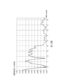
請配合參照第1圖至第3圖,第2圖係繪示依照第1圖實施方式之槽孔天線結構100之電壓駐波比(VSWR)圖;及第3圖係繪示依照第1圖實施方式之槽孔天線結構100之效率的示意圖。第2圖係繪示槽孔天線結構100對應各頻率之電壓駐波比,當電壓駐波比小於2時,可接收到品質較佳之訊號。第一槽孔121的一共振頻率介於6.2G赫茲(Hz)到7.1GHz之間。第二槽孔122的一共振頻率介於5.1GHz到6.1GHz之間。第三槽孔123的一共振頻率介於2.4GHz到2.5GHz之間。Please refer to Figures 1 to 3. Figure 2 is a diagram showing a voltage-to-wave ratio (VSWR) of the slot antenna structure 100 according to the implementation of Figure 1; and Figure 3 is a diagram showing the efficiency of the slot antenna structure 100 according to the implementation of Figure 1. Figure 2 shows the voltage-to-wave ratio of the slot antenna structure 100 corresponding to each frequency. When the voltage-to-wave ratio is less than 2, a better quality signal can be received. A resonant frequency of the first slot 121 is between 6.2 GHz and 7.1 GHz. A resonant frequency of the second slot 122 is between 5.1 GHz and 6.1 GHz. A resonant frequency of the third slot 123 is between 2.4 GHz and 2.5 GHz.
由第2圖可知,槽孔天線結構100的頻率介於2.4GHz到2.5GHz之間、5.1GHz到6.1GHz之間及6.7GHz到7.1GHz之間時的電壓駐波比皆小於2,槽孔天線結構100的頻率在6.2GHz到6.7GHz之間時的電壓駐波比僅略大於2,因此在上述頻率範圍內時皆可收到品質較佳的訊號。由第3圖可知,本發明之槽孔天線結構100在上述頻率範圍內的效率皆高於30%,進一步來說,槽孔天線結構100在頻率介於2.4GHz到2.5GHz之間以及5.1GHz到5.9GHz之間時,效率甚至可高於40%。As shown in FIG. 2, the voltage-to-wave ratio of the slot antenna structure 100 is less than 2 when the frequency is between 2.4 GHz and 2.5 GHz, between 5.1 GHz and 6.1 GHz, and between 6.7 GHz and 7.1 GHz. The voltage-to-wave ratio of the slot antenna structure 100 is only slightly greater than 2 when the frequency is between 6.2 GHz and 6.7 GHz. Therefore, a good quality signal can be received within the above frequency range. As shown in FIG. 3, the efficiency of the slot antenna structure 100 of the present invention within the above frequency range is higher than 30%. Specifically, the efficiency of the slot antenna structure 100 can even be higher than 40% when the frequency is between 2.4 GHz and 2.5 GHz and between 5.1 GHz and 5.9 GHz.
第一長度L1可大於等於第一槽孔121之一共振頻率的1/4倍波長,且可小於等於共振頻率的3/4倍波長。第二長度L2可大於等於第二槽孔122之一共振頻率的1/4倍波長,且可小於等於共振頻率的1/2倍波長。第三長度L3可大於等於第三槽孔123之一共振頻率的1/4倍波長,且可小於等於共振頻率的1/2倍波長。The first length L1 may be greater than or equal to 1/4 times the wavelength of a resonant frequency of the first slot 121, and may be less than or equal to 3/4 times the wavelength of the resonant frequency. The second length L2 may be greater than or equal to 1/4 times the wavelength of a resonant frequency of the second slot 122, and may be less than or equal to 1/2 times the wavelength of the resonant frequency. The third length L3 may be greater than or equal to 1/4 times the wavelength of a resonant frequency of the third slot 123, and may be less than or equal to 1/2 times the wavelength of the resonant frequency.
藉此,本發明之槽孔天線結構100將金屬件120配置為具有三個閉槽孔(即第一槽孔121、第二槽孔122及第三槽孔123),激發出共振頻率介於2.4GHz到2.5GHz之間、5.1GHz到6.1GHz之間及6.2GHz到7.1GHz之間的訊號。Thus, the slot antenna structure 100 of the present invention configures the metal member 120 to have three closed slots (i.e., the first slot 121, the second slot 122, and the third slot 123) to excite signals with resonance frequencies between 2.4 GHz and 2.5 GHz, between 5.1 GHz and 6.1 GHz, and between 6.2 GHz and 7.1 GHz.
請參照第1圖及第4圖,第4圖係繪示本發明之第二實施例之電子裝置10之示意圖。電子裝置10包含一殼體400及一槽孔天線結構300。槽孔天線結構300設置於殼體400。槽孔天線結構300包含天線單元(見第1圖之天線單元110)及金屬件(見第1圖之金屬件120)。金屬件電性連接天線單元,並包含一第一槽孔321、第二槽孔322及第三槽孔323。在本實施方式中,槽孔天線結構300可與第1圖實施方式之槽孔天線結構100相同,不再贅述。電子裝置10可為筆記型電腦、個人數位助理或其他攜帶型電子裝置,但本發明不以此為限。詳細地說,天線單元可設置於電子裝置10的殼體400內部的電路板(圖未繪示),而金屬件可設置於殼體400的表面(例如筆記型電腦之A面),但本發明不以此為限。Please refer to FIG. 1 and FIG. 4. FIG. 4 is a schematic diagram of an
藉此,本發明之電子裝置10將槽孔天線結構300完全嵌入殼體400,使無線傳輸設備達成雙頻段的傳送及接收功能。Thus, the
由上述實施方式可知,本發明具有下列優點,其一,本發明之槽孔天線結構利用三個槽孔(即第一槽孔、第二槽孔及第三槽孔)激發出多個頻帶的發射訊號;其二,本發明之槽孔天線結構將槽孔的寬度縮小為1毫米,將金屬件的長度(即第一長度、第二長度、第三長度、間距及另一間距之和)縮短為80毫米,在縮小孔天線結構的整體尺寸的同時,激發出多個頻帶的發射訊號;其三,本發明之槽孔天線結構將金屬件配置為具有三個閉槽孔(即第一槽孔、第二槽孔及第三槽孔),激發出共振頻率介於2.4GHz到2.5GHz之間、5.1GHz到6.1GHz之間及6.2GHz到7.1GHz之間的訊號;其四,本發明之電子裝置將槽孔天線結構完全嵌入殼體,使無線傳輸設備達成雙頻段的傳送及接收功能。It can be seen from the above implementation that the present invention has the following advantages. First, the slot antenna structure of the present invention utilizes three slots (i.e., the first slot, the second slot, and the third slot) to stimulate transmission signals of multiple frequency bands. Second, the slot antenna structure of the present invention reduces the width of the slot to 1 mm and shortens the length of the metal part (i.e., the sum of the first length, the second length, the third length, the spacing, and another spacing) to 80 mm. While reducing the overall size of the slot antenna structure, multiple transmission signals are stimulated. frequency band transmission signal; thirdly, the slot antenna structure of the present invention configures the metal part to have three closed slots (i.e., the first slot, the second slot, and the third slot) to excite the signals with resonance frequencies between 2.4 GHz and 2.5 GHz, between 5.1 GHz and 6.1 GHz, and between 6.2 GHz and 7.1 GHz; fourthly, the electronic device of the present invention completely embeds the slot antenna structure into the casing, so that the wireless transmission equipment can achieve dual-band transmission and reception functions.
雖然本發明已以實施方式揭露如上,然其並非用以限定本發明,任何熟習此技藝者,在不脫離本發明之精神和範圍內,當可作各種之更動與潤飾,因此本發明之保護範圍當視後附之申請專利範圍所界定者為準。Although the present invention has been disclosed in the above embodiments, it is not intended to limit the present invention. Anyone skilled in the art can make various changes and modifications without departing from the spirit and scope of the present invention. Therefore, the scope of protection of the present invention shall be subject to the scope of the attached patent application.
10:電子裝置 100,300:槽孔天線結構 110:天線單元 120:金屬件 121,321:第一槽孔 122,322:第二槽孔 123,323:第三槽孔 400:殼體 D:方向 F:饋入點 G1,G2:間距 L1:第一長度 L2:第二長度 L3:第三長度 W:寬度 10: Electronic device 100,300: Slot antenna structure 110: Antenna unit 120: Metal parts 121,321: First slot 122,322: Second slot 123,323: Third slot 400: Housing D: Direction F: Feed point G1,G2: Spacing L1: First length L2: Second length L3: Third length W: Width
第1圖係繪示本發明之第一實施例之槽孔天線結構之示意圖; 第2圖係繪示依照第1圖實施方式之槽孔天線結構之電壓駐波比圖; 第3圖係繪示依照第1圖實施方式之槽孔天線結構之效率的示意圖;及 第4圖係繪示本發明之第二實施例之電子裝置之示意圖。 FIG. 1 is a schematic diagram showing a slot antenna structure of the first embodiment of the present invention; FIG. 2 is a diagram showing a voltage-to-wave ratio of the slot antenna structure according to the embodiment of FIG. 1; FIG. 3 is a schematic diagram showing the efficiency of the slot antenna structure according to the embodiment of FIG. 1; and FIG. 4 is a schematic diagram showing an electronic device of the second embodiment of the present invention.
100:槽孔天線結構 110:天線單元 120:金屬件 121:第一槽孔 122:第二槽孔 123:第三槽孔 D:方向 F:饋入點 G1,G2:間距 L1:第一長度 L2:第二長度 L3:第三長度 W:寬度 100: Slot antenna structure 110: Antenna unit 120: Metal parts 121: First slot 122: Second slot 123: Third slot D: Direction F: Feed point G1, G2: Spacing L1: First length L2: Second length L3: Third length W: Width
Claims (18)
Priority Applications (2)
| Application Number | Priority Date | Filing Date | Title |
|---|---|---|---|
| TW111129879A TWI838818B (en) | 2022-08-09 | 2022-08-09 | Slot antenna structure and electronic device |
| US18/333,585 US20240055769A1 (en) | 2022-08-09 | 2023-06-13 | Slot antenna structure and electronic device |
Applications Claiming Priority (1)
| Application Number | Priority Date | Filing Date | Title |
|---|---|---|---|
| TW111129879A TWI838818B (en) | 2022-08-09 | 2022-08-09 | Slot antenna structure and electronic device |
Publications (2)
| Publication Number | Publication Date |
|---|---|
| TW202408084A TW202408084A (en) | 2024-02-16 |
| TWI838818B true TWI838818B (en) | 2024-04-11 |
Family
ID=89845515
Family Applications (1)
| Application Number | Title | Priority Date | Filing Date |
|---|---|---|---|
| TW111129879A TWI838818B (en) | 2022-08-09 | 2022-08-09 | Slot antenna structure and electronic device |
Country Status (2)
| Country | Link |
|---|---|
| US (1) | US20240055769A1 (en) |
| TW (1) | TWI838818B (en) |
Citations (5)
| Publication number | Priority date | Publication date | Assignee | Title |
|---|---|---|---|---|
| TW200845486A (en) * | 2007-05-04 | 2008-11-16 | Clevo Co | Multiband planar antenna and electrical apparatus using the same |
| TW201705610A (en) * | 2015-07-31 | 2017-02-01 | 宏碁股份有限公司 | Mobile communication device |
| TW201735444A (en) * | 2016-03-17 | 2017-10-01 | 宏碁股份有限公司 | Mobile device |
| CN209119323U (en) * | 2018-09-30 | 2019-07-16 | 明澜(南京)电子有限公司 | A kind of 120 ° of orientation high-gain aerials |
| CN113675588A (en) * | 2020-05-15 | 2021-11-19 | 深圳富泰宏精密工业有限公司 | Electronic device |
Family Cites Families (4)
| Publication number | Priority date | Publication date | Assignee | Title |
|---|---|---|---|---|
| TWI260817B (en) * | 2005-05-05 | 2006-08-21 | Ind Tech Res Inst | Wireless apparatus capable to control radiation patterns of antenna |
| TWI628858B (en) * | 2016-07-12 | 2018-07-01 | 中華電信股份有限公司 | Electronically switched beam direction array antenna |
| TWI635653B (en) * | 2017-04-18 | 2018-09-11 | 華碩電腦股份有限公司 | Antenna element |
| CN111987466B (en) * | 2019-05-24 | 2022-10-25 | 杭州海康威视数字技术股份有限公司 | Slot antenna and electronic equipment comprising same |
-
2022
- 2022-08-09 TW TW111129879A patent/TWI838818B/en active
-
2023
- 2023-06-13 US US18/333,585 patent/US20240055769A1/en active Pending
Patent Citations (5)
| Publication number | Priority date | Publication date | Assignee | Title |
|---|---|---|---|---|
| TW200845486A (en) * | 2007-05-04 | 2008-11-16 | Clevo Co | Multiband planar antenna and electrical apparatus using the same |
| TW201705610A (en) * | 2015-07-31 | 2017-02-01 | 宏碁股份有限公司 | Mobile communication device |
| TW201735444A (en) * | 2016-03-17 | 2017-10-01 | 宏碁股份有限公司 | Mobile device |
| CN209119323U (en) * | 2018-09-30 | 2019-07-16 | 明澜(南京)电子有限公司 | A kind of 120 ° of orientation high-gain aerials |
| CN113675588A (en) * | 2020-05-15 | 2021-11-19 | 深圳富泰宏精密工业有限公司 | Electronic device |
Also Published As
| Publication number | Publication date |
|---|---|
| US20240055769A1 (en) | 2024-02-15 |
| TW202408084A (en) | 2024-02-16 |
Similar Documents
| Publication | Publication Date | Title |
|---|---|---|
| CN1879256B (en) | Antenna, manufacturing method thereof, and portable wireless terminal using the same | |
| US6930640B2 (en) | Dual frequency band inverted-F antenna | |
| US20090079639A1 (en) | Antenna Device and Electronic Apparatus | |
| TWI758164B (en) | Antenna structure | |
| TWI757163B (en) | Antenna structure | |
| TW202121740A (en) | Antenna structure | |
| US10916847B2 (en) | Multi-band antenna | |
| WO2004097980A1 (en) | Wideband flat antenna | |
| TW202121746A (en) | Antenna structure | |
| JP2015023394A (en) | Wireless module | |
| TWI892206B (en) | Antenna structure and heat dissipation device | |
| US20070057855A1 (en) | Portable information apparatus incorporating wireless communication antenna | |
| TW202329533A (en) | Antenna structure | |
| JP2003347828A (en) | Antenna device and wireless card module | |
| TWI838818B (en) | Slot antenna structure and electronic device | |
| TWI381588B (en) | An antenna for receiving electric waves, an electronic device with the antenna and the manufacturing method of the antenna | |
| TW202401897A (en) | Mobile device with high radiation efficiency | |
| TWI885445B (en) | Antenna structure | |
| TWI873799B (en) | Antenna structure and electronic device | |
| TWI827202B (en) | Open loop antenna and electronic device | |
| TW202145644A (en) | Antenna structure | |
| TWI827123B (en) | Antenna structure and communication device | |
| CN100421300C (en) | Antenna device and design method thereof | |
| US7633447B2 (en) | Antenna device to be loaded into an information processing apparatus | |
| CN117673755A (en) | Slot antenna structure and electronic device |