TW202305405A - Method and system for detecting and analyzing objects - Google Patents
Method and system for detecting and analyzing objects Download PDFInfo
- Publication number
- TW202305405A TW202305405A TW110114549A TW110114549A TW202305405A TW 202305405 A TW202305405 A TW 202305405A TW 110114549 A TW110114549 A TW 110114549A TW 110114549 A TW110114549 A TW 110114549A TW 202305405 A TW202305405 A TW 202305405A
- Authority
- TW
- Taiwan
- Prior art keywords
- image
- radar
- visible light
- camera
- calibration
- Prior art date
Links
- 238000000034 method Methods 0.000 title claims abstract description 22
- 239000011159 matrix material Substances 0.000 claims description 65
- 230000004927 fusion Effects 0.000 claims description 50
- 238000012937 correction Methods 0.000 claims description 31
- 238000012545 processing Methods 0.000 claims description 26
- 230000009977 dual effect Effects 0.000 claims description 16
- 238000006243 chemical reaction Methods 0.000 claims description 15
- 230000010354 integration Effects 0.000 claims description 13
- 230000009466 transformation Effects 0.000 claims description 6
- 238000004364 calculation method Methods 0.000 claims description 4
- 230000001360 synchronised effect Effects 0.000 claims description 3
- 238000002372 labelling Methods 0.000 abstract 1
- 230000000694 effects Effects 0.000 description 10
- 238000001514 detection method Methods 0.000 description 5
- 238000005516 engineering process Methods 0.000 description 5
- 238000003384 imaging method Methods 0.000 description 4
- 238000010586 diagram Methods 0.000 description 3
- 238000013473 artificial intelligence Methods 0.000 description 2
- 238000013135 deep learning Methods 0.000 description 2
- 230000003137 locomotive effect Effects 0.000 description 2
- 238000012800 visualization Methods 0.000 description 2
- 230000008859 change Effects 0.000 description 1
- 239000003086 colorant Substances 0.000 description 1
- 239000000428 dust Substances 0.000 description 1
- 239000004744 fabric Substances 0.000 description 1
- 238000004519 manufacturing process Methods 0.000 description 1
- 230000007246 mechanism Effects 0.000 description 1
- 238000012986 modification Methods 0.000 description 1
- 230000004048 modification Effects 0.000 description 1
- 230000008569 process Effects 0.000 description 1
- 239000000779 smoke Substances 0.000 description 1
- 239000000126 substance Substances 0.000 description 1
- 238000012549 training Methods 0.000 description 1
- 230000000007 visual effect Effects 0.000 description 1
Images


Landscapes
- Radar Systems Or Details Thereof (AREA)
- Image Processing (AREA)
- Image Analysis (AREA)
- Ultra Sonic Daignosis Equipment (AREA)
- Supplying Of Containers To The Packaging Station (AREA)
- Color Television Image Signal Generators (AREA)
- Studio Devices (AREA)
Abstract
Description
本發明是有關於一種物件距離偵測方法,特別是指一種融合可見光相機、熱感攝影機、毫米波雷達和人工智慧物件辨識模型之偵測物件並標記距離的方法。The present invention relates to a method for object distance detection, in particular to a method for detecting objects and marking distances by integrating visible light cameras, thermal cameras, millimeter-wave radars and artificial intelligence object recognition models.
可見光相機(RGB Camera)在天候良好、光線明亮時,其拍攝範圍內之物件成像效果良好,但在光線昏暗,如夜晚無光源處,其成像效果則與光線強弱成反比。而在雨、雪、霧等天候不良或有煙、塵的環境時,則易遭遮蔽且無法穿透,成像效果不佳,以致影響辨識影像中之物件的識別率。When the visible light camera (RGB Camera) has good weather and bright light, the imaging effect of the objects within its shooting range is good, but when the light is dim, such as at night without a light source, the imaging effect is inversely proportional to the light intensity. In rainy, snowy, foggy and other bad weather or in environments with smoke and dust, it is easy to be covered and impenetrable, and the imaging effect is not good, which affects the recognition rate of objects in the image.
熱感攝影機(或稱紅外線相機,Thermal Camera)在天候不佳或光線昏暗環境下,其成像效果較可見光相機佳,但熱感攝影機僅能描繪物件的外型,不能顯示物件的細節輪廓,例如無法顯示人臉的細部特徵,且當所拍攝的相鄰物件溫度相近時,熱感攝影機易混淆相鄰物件而影響辨識影像中之物件的識別率。Thermal cameras (or infrared cameras, Thermal Cameras) have better imaging effects than visible light cameras in poor weather or dim light environments, but thermal cameras can only describe the appearance of objects, and cannot display the details of objects, such as The detailed features of the human face cannot be displayed, and when the temperature of the adjacent objects captured is similar, the thermal camera is likely to confuse the adjacent objects and affect the recognition rate of the objects in the image.
毫米波雷達(mmWaveRadar)具有偵測物件之距離、相對速度與角度之能力,對許多物質如塑膠、乾燥牆壁、布料等亦能穿透,且不受不良天候與光線影響,具有全天候的工作能力。但因其解析度低,無法顯示物件立面,故僅能偵測有無物件存在,卻無法辨別物件為何。Millimeter wave radar (mmWaveRadar) has the ability to detect the distance, relative speed and angle of objects, and can penetrate many substances such as plastic, dry walls, cloth, etc., and is not affected by bad weather and light, and has all-weather working ability . However, due to its low resolution, it cannot display the facade of the object, so it can only detect whether the object exists, but cannot identify the object.
因此,若能融合前述三種感測器的優勢,透過大量的可見光影像和熱影像資料藉由深度學習建立人工智慧(AI)模型,俾能對周遭物件進行辨識及標註,同時藉由毫米波雷達偵測物件的距離,將可全天候地提供周遭物件的訊息給人或電腦進行判斷而能適時地採取適當及必要之作為。Therefore, if the advantages of the aforementioned three sensors can be integrated, an artificial intelligence (AI) model can be established through deep learning through a large amount of visible light images and thermal image data, so that the surrounding objects can be identified and marked. Detecting the distance of objects will be able to provide information about surrounding objects to people or computers around the clock to make judgments and take appropriate and necessary actions in a timely manner.
因此,本發明之目的,即在提供一種偵測物件並標記距離的方法和系統,其融合可見光攝影機、熱感攝影機和毫米波雷達三種感測器,並運用以大量的可見光影像和熱影像資料進行深度學習而訓練出的影像物件辨識模型和毫米波雷達,對周遭物件進行自動化及全天候偵測並標記物件的距離。Therefore, the purpose of the present invention is to provide a method and system for detecting objects and marking the distance, which integrates three sensors of visible light camera, thermal camera and millimeter wave radar, and uses a large amount of visible light image and thermal image data The image object recognition model and millimeter-wave radar trained by deep learning can automatically and all-weather detect the surrounding objects and mark the distance of the objects.
於是,本發明一種偵測物件並標記距離的方法,是由一偵測物件並標記距離的系統來實現,該系統包括一熱感攝影機、一與該熱感攝影機相鄰地固定於一攝影位置的可見光攝影機、一固定於該攝影位置的下方的毫米波雷達,以及一影像處理裝置,其與該熱感攝影機、該可見光攝影機及該毫米波雷達電連接並控制三者同步動作;該方法包括下列步驟。Therefore, a method for detecting an object and marking a distance in the present invention is realized by a system for detecting an object and marking a distance. a visible light camera, a millimeter-wave radar fixed below the photographing position, and an image processing device, which is electrically connected to the thermal camera, the visible light camera and the millimeter-wave radar and controls the synchronous actions of the three; the method includes Follow the steps below.
(A)令該熱感攝影機、該可見光攝影機和該毫米波雷達同步動作,使該熱感攝影機拍攝一場景以獲得的一熱影像,並使該可見光攝影機拍攝該場景以獲得一可見光影像,以及使該毫米波雷達偵測該場景以獲得的一雷達空間資訊,該雷達空間資訊包含該場景中被該毫米波雷達偵測到的每一物件的多個雷達點座標;其中該熱感攝影機與該可見光攝影機相鄰地固定於一攝影位置,該毫米波雷達固定於該攝影位置的下方。(A) making the thermal camera, the visible light camera and the millimeter-wave radar act synchronously, causing the thermal camera to shoot a scene to obtain a thermal image, and causing the visible light camera to shoot the scene to obtain a visible light image, and A radar spatial information obtained by detecting the scene with the millimeter-wave radar, the radar spatial information includes a plurality of radar point coordinates of each object detected by the millimeter-wave radar in the scene; wherein the thermal camera and The visible light camera is adjacently fixed at a shooting position, and the millimeter-wave radar is fixed below the shooting position.
(B)該影像處理裝置的一雙影像融合模組根據該可見光影像校正該熱影像,以產生一校正後熱影像,且將該校正後熱影像與該可見光影像相疊合形成一融合影像。(B) A dual image fusion module of the image processing device corrects the thermal image according to the visible light image to generate a corrected thermal image, and superimposes the corrected thermal image and the visible light image to form a fusion image.
(C)該影像處理裝置的一座標轉換模組根據該雷達空間資訊繪製一呈現該等雷達點座標的雷達點座標圖,且該座標轉換模組根據一雷達至相機之投影矩陣,將該雷達點座標圖中的該等雷達點座標投影至該融合影像上而產生一具有雷達資訊的融合影像。(C) The coordinate conversion module of the image processing device draws a radar point coordinate map showing the coordinates of the radar points according to the radar spatial information, and the coordinate conversion module draws the radar point coordinates according to a radar-to-camera projection matrix The radar point coordinates in the point coordinate map are projected onto the fused image to generate a fused image with radar information.
(D)該影像處理裝置的一影像物件辨識模組根據該校正後熱影像和該可見光影像辨識影像中的物件,並在該融合影像中框選出被辨識的物件而產生一呈現物件資訊的融合影像。(D) An image object recognition module of the image processing device recognizes the object in the image according to the corrected thermal image and the visible light image, and selects the recognized object in the fused image to generate a fusion of presented object information image.
(E)該影像處理裝置的一影像整合模組根據該具有雷達資訊的融合影像及該呈現物件資訊的融合影像,排除該具有雷達資訊的融合影像中未對應落在該呈現物件資訊的融合影像之被框選的物件中的該等雷達點座標,並以對應落在該呈現物件資訊的融合影像之被框選的物件中的該等雷達點座標其中與該毫米波雷達距離最近的該雷達點座標,計算該呈現物件資訊的融合影像之被框選的物件與該毫米波雷達的一實際距離,並在該呈現物件資訊的融合影像之被框選的物件處標示該實際距離,以產生並輸出一最終影像,該最終影像呈現被框選的物件及該實際距離。(E) An image integration module of the image processing device, based on the fused image with radar information and the fused image with the presented object information, excludes the fused image with radar information that does not correspond to the fused image with the presented object information The coordinates of the radar points in the framed object, and corresponding to the coordinates of the radar points in the framed object of the fused image that presents the object information, the radar that is closest to the millimeter-wave radar point coordinates, calculate an actual distance between the framed object of the fused image presenting object information and the millimeter-wave radar, and mark the actual distance at the framed object of the fused image presenting object information to generate And output a final image, the final image presents the framed object and the actual distance.
在本發明的一些實施態樣中,該座標轉換模組需先取得該雷達至相機之投影矩陣,而獲得該雷達至相機之投影矩陣的方法包括:(C1) 將一校正板放置在一空間中,並令該可見光攝影機拍攝該校正板以獲得一校正用可見光影像,並令該毫米波雷達偵測該空間以獲得一校正用雷達空間資訊,該校正用雷達空間資訊包含該校正板的多個雷達點座標;及(C2)一電腦裝置根據該校正用雷達空間資訊繪製一呈現該校正板的該等雷達點座標的校正用雷達點座標圖,並利用透視變換原理,根據該校正用可見光影像中的該校正板影像與該校正用雷達點座標圖之該校正板的該等雷達點座標的關連性,計算得到將該等雷達點座標投影至該校正用可見光影像中的該校正板影像上的一單應性矩陣,並以該單應性矩陣做為該雷達至相機之投影矩陣。In some embodiments of the present invention, the coordinate conversion module needs to first obtain the projection matrix from the radar to the camera, and the method for obtaining the projection matrix from the radar to the camera includes: (C1) placing a calibration plate in a space , and let the visible light camera photograph the calibration plate to obtain a visible light image for calibration, and let the millimeter-wave radar detect the space to obtain radar spatial information for calibration, the radar spatial information for calibration includes multiple information of the calibration plate radar point coordinates; and (C2) a computer device draws a calibration radar point coordinate map showing the radar point coordinates of the calibration plate based on the calibration radar spatial information, and uses the principle of perspective transformation, according to the calibration with visible light The correlation between the calibration plate image in the image and the radar point coordinates of the calibration plate in the calibration radar point coordinate map is calculated to obtain the calibration plate image by projecting the radar point coordinates into the calibration visible light image A homography matrix on , and use the homography matrix as the projection matrix from the radar to the camera.
在本發明的一些實施態樣中,該可見光攝影機使用非廣角鏡頭時,該雙影像融合模組還獲得校正該可見光攝影機的一內部參數矩陣,且該雙影像融合模組根據該內部參數矩陣校正該可見光影像而產生一校正後可見光影像,再將該校正後熱影像與該校正後可見光影像相疊合形成該融合影像;且該電腦裝置還根據該內部參數矩陣校正該校正用可見光影像而產生一校正後可見光影像,且根據該校正後可見光影像中的該校正板影像與該校正用雷達點座標圖之該校正板的該等雷達點座標的關連性,計算得到該單應性矩陣。In some implementation aspects of the present invention, when the visible light camera uses a non-wide-angle lens, the dual image fusion module also obtains an internal parameter matrix for correcting the visible light camera, and the dual image fusion module corrects the internal parameter matrix according to the internal parameter matrix. visible light image to generate a corrected visible light image, and then superimpose the corrected thermal image and the corrected visible light image to form the fusion image; and the computer device also corrects the corrected visible light image according to the internal parameter matrix to generate a The corrected visible light image, and the homography matrix is calculated according to the correlation between the calibration plate image in the corrected visible light image and the radar point coordinates of the calibration plate in the calibration radar point coordinate map.
在本發明的一些實施態樣中,該可見光攝影機使用廣角鏡頭時,該雙影像融合模組還獲得校正該可見光攝影機的一魚眼校正矩陣,且該雙影像融合模組根據該魚眼校正矩陣校正該可見光影像而產生一校正後可見光影像,再將該校正後熱影像與該校正後可見光影像相疊合形成該融合影像;且該電腦裝置還根據該魚眼校正矩陣校正該校正用可見光影像而產生一校正後可見光影像,且根據該校正後可見光影像中的該校正板影像與該校正用雷達點座標圖之該校正板的該等雷達點座標的關連性,計算得到該單應性矩陣。In some implementation aspects of the present invention, when the visible light camera uses a wide-angle lens, the dual-image fusion module also obtains a fisheye correction matrix for correcting the visible light camera, and the dual-image fusion module corrects according to the fisheye correction matrix The visible light image generates a corrected visible light image, and then the corrected thermal image is superimposed with the corrected visible light image to form the fusion image; and the computer device also corrects the corrected visible light image according to the fisheye correction matrix A corrected visible light image is generated, and the homography matrix is calculated according to the correlation between the calibration plate image in the corrected visible light image and the radar point coordinates of the calibration plate in the calibration radar point coordinate map.
本發明之功效在於:藉由融合上述的該熱感攝影機、該可見光攝影機和該毫米波雷達三種感測器的優勢,產生該融合影像,並藉由同時根據熱影像和可見光影像進行物件的辨識,而產生該呈現物件資訊的融合影像,且利用該毫米波雷達偵測產生的雷達空間資訊製作雷達點座標圖,並將雷達點座標圖投影至該融合影像而產生該具有雷達資訊的融合影像,並且藉由整合該呈現物件資訊的融合影像和該具有雷達資訊的融合影像,計算出物件與該毫米波雷達之間的該實際距離,而產生呈現被辨識的物件及其與該毫米波雷達的該實際距離的該最終影像,並且能將環境或天候的影響降到最低,而能夠提供全天候周遭物件的偵測訊息給人或電腦進行判斷,使人或電腦能適時地採取適當及必要之作為。The effect of the present invention is to generate the fused image by combining the advantages of the thermal camera, the visible light camera and the millimeter-wave radar, and identify objects based on the thermal image and the visible light image at the same time , and generate the fused image of the presenting object information, and use the radar space information generated by the millimeter-wave radar detection to make a radar point coordinate map, and project the radar point coordinate map to the fused image to generate the fused image with radar information , and calculate the actual distance between the object and the millimeter-wave radar by integrating the fused image presenting object information and the fused image with radar information, and generate the identified object and its relationship with the millimeter-wave radar The final image of the actual distance can be minimized, and the impact of the environment or weather can be minimized, and the detection information of surrounding objects can be provided to humans or computers for judgment, so that humans or computers can take appropriate and necessary actions in a timely manner. as.
在本發明被詳細描述之前,應當注意在以下的說明內容中,類似的元件是以相同的編號來表示。Before the present invention is described in detail, it should be noted that in the following description, similar elements are denoted by the same numerals.
參閱圖1所示,是本發明偵測物件並標記距離的方法的一實施例的主要流程圖,且如圖2所示,本實施例主要應用(但不限)於一車輛100上,並且由一偵測物件並標記距離的系統來實現,該系統主要包括一熱感攝影機1、一可見光攝影機2、一毫米波雷達3及一影像處理裝置4,該熱感攝影機1與該可見光攝影機2相鄰地固定於一攝影位置,例如該車輛100的車頂並朝向車輛100的前方,該毫米波雷達3固定於該攝影位置的下方,例如該車輛100的車頭前方中間靠近車牌的位置並朝向車輛100的前方,該影像處理裝置4設於該車輛100的內部,並與該熱感攝影機1、該可見光攝影機2及該毫米波雷達3電連接以控制三者同步動作。且如圖3所示,該影像處理裝置4可以是但不限於一微電腦(或車用電腦)並包含一雙影像融合模組41、一座標轉換模組42、一影像物件辨識模組43及一影像整合模組44,且上述模組可以是被該影像處理裝置4中的例如中央處理器及/或影像處理器等執行的程式軟體,但並不以此為限,上述模組也可以韌體或軟體與硬體結合的方式實現。Referring to FIG. 1, it is a main flowchart of an embodiment of the method for detecting objects and marking distances according to the present invention, and as shown in FIG. 2, this embodiment is mainly applied (but not limited) to a
藉此,當車輛100被行駛於路上且該偵測物件並標記距離的系統被啟動後,如圖1的步驟S1,該影像處理裝置4令該熱感攝影機1、該可見光攝影機2和該毫米波雷達3同步動作,使該熱感攝影機1拍攝車輛100前方的一場景,以獲得如圖4所示的一熱影像11,同時令該可見光攝影機2拍攝該場景以獲得如圖4所示的一可見光影像21,並且同時令該毫米波雷達3偵測該場景以獲得的一雷達空間資訊,該雷達空間資訊包含在該場景中被該毫米波雷達3偵測到的每一物件的多個雷達點座標。Thus, when the
接著,如圖1的步驟S2,該影像處理裝置4應用其中的該雙影像融合模組41,根據該可見光影像21校正該熱影像11,以產生一能與該可見光影像21良好地融合之校正後熱影像11’,且將該校正後熱影像11’與該可見光影像21相疊合,而形成如圖4所示的一融合影像20。且該雙影像融合模組41產生該融合影像20的方法可參考同一申請人在台灣第110104936號專利申請案中提出的雙影像融合技術,故在此不予詳述。不過,本案並不限於只能使用上述申請案之方法產生該融合影像20。並且,該雙影像融合模組41將該融合影像20提供給該座標轉換模組42,並將該校正後熱影像11’、該可見光影像21及該融合影像20提供給該影像物件辨識模組43。Next, as shown in step S2 of FIG. 1 , the image processing device 4 applies the dual
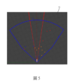
此外,如圖1的步驟S3和圖3所示,該影像處理裝置4應用其中的該座標轉換模組42,從該雷達空間資訊中獲取(提取)該毫米波雷達3在該場景中偵測到的每一個物件的該等雷達點座標,並利用一視覺化軟體套件,例如但不限於Rviz(Ros visualization)軟體,根據該等雷達點座標繪製產生如圖5所示二維的雷達點座標圖51(其中顯示的每一個點代表該處有物件,且每一個點實際上是多個雷達點座標聚集在一起)。然後,該座標轉換模組42根據一雷達(該毫米波雷達3)至相機(該可見光相機2)之投影矩陣,將該雷達點座標圖51中的該等雷達點座標投影至該融合影像20上,而產生如圖6所示之一具有雷達資訊的融合影像61。In addition, as shown in step S3 of FIG. 1 and FIG. 3 , the image processing device 4 uses the
具體而言,該座標轉換模組42需先取得該雷達至相機之投影矩陣,而獲得該雷達至相機之投影矩陣的方法類似台灣第110104936號專利申請案中獲得單應性矩陣的做法,如圖7的步驟S71,首先,將一校正板放置在一空間中,並令該可見光攝影機2拍攝該校正板以獲得一校正用可見光影像,同時令該毫米波雷達3偵測該空間以獲得一校正用雷達空間資訊,該校正用雷達空間資訊包含對應於該校正板的多個雷達點座標;然後,如圖7的步驟S72,利用一電腦裝置從該校正用雷達空間資訊中獲取該等雷達點座標,並利用例如上述的視覺化軟體套件,Rviz(Ros visualization)軟體,根據從該校正用雷達空間資訊中獲取該等校正用雷達點座標繪製產生類似圖5所示的一校正用雷達點座標圖(此圖中的全部或大部分雷達點都會集中在對應於該校正用可見光影像中的該校正板影像的位置),然後,該電腦裝置再利用透視變換原理,根據該校正用可見光影像中的該校正板影像與該校正用雷達點座標圖中的該等雷達點座標的關連性,計算得到將該校正用雷達點座標圖中的該等雷達點座標投影至該校正用可見光影像中的該校正板影像上的一單應性矩陣,而以該單應性矩陣做為上述的該雷達至相機之投影矩陣。Specifically, the
此外,若考量到該可見光攝影機2採用非廣角鏡頭(例如一般標準鏡頭)時,該可見光攝影機2可能存在因攝影機內部的機構、感光元件和鏡頭等因素所造成的影像失真,在本實施例中,還可尋找該可見光攝影機2的一內部參數矩陣,以利用該內部參數矩陣來校正該可見光攝影機2所拍攝的可見光影像,以校正該可見光攝影機2,且由於尋找該可見光攝影機2的該內部參數矩陣已是一習知技術且非本發明重點所在,故在此不予贅述;因此,在上述步驟S72中,該電腦裝置還可預先獲得校正該可見光攝影機2的該內部參數矩陣,然後,根據該內部參數矩陣校正該校正用可見光影像而產生一再校正可見光影像,再根據該再校正可見光影像與該校正用雷達點座標圖計算得到該單應性矩陣。In addition, if it is considered that the
因此,在上述步驟S2中,該雙影像融合模組41也會先根據該內部參數矩陣校正該可見光影像21而產生校正後可見光影像21,再將該校正後熱影像11’與該校正後可見光影像21相疊合形成該融合影像20,再將該融合影像20提供給該座標轉換模組42。Therefore, in the above-mentioned step S2, the dual-
或者,當該可見光攝影機2是採用廣角鏡頭(例如魚眼鏡頭)時,該可見光攝影機2則需要藉由一魚眼校正矩陣進行魚眼校正,以將所拍攝之具有魚眼效果(產生變形)的可見光影像轉換成不具有魚眼效果的可見光影像,此時,在本實施例中,則需尋找該可見光攝影機2的一魚眼校正矩陣,以利用該魚眼校正矩陣來校正該可見光攝影機2所拍攝的該可見光影像21,而由於獲得該魚眼校正矩陣之技術手段已是一習知技術且非本發明重點所在,故在此不予贅述;因此,在上述步驟S72中,當該電腦裝置獲得該魚眼校正矩陣後,即可應用該魚眼校正矩陣來校正該校正用可見光影像。同理,在此實施態樣下,在上述步驟S2中,該雙影像融合模組41也會先根據該魚眼校正矩陣校正該可見光影像21而產生校正後可見光影像21,再將該校正後熱影像11’與該校正後可見光影像21相疊合形成該融合影像20,再將該融合影像20提供給該座標轉換模組42。Or, when the
再者,如圖1的步驟S4和圖3所示,該影像處理裝置4應用其中的一影像物件辨識模組43根據該校正後熱影像11’和該可見光影像21辨識影像中的物件,並在該融合影像20中框選出被辨識的物件並標註其類別,例如圖8所示,將該融合影像20中被辨識的物件以一物件框810框選起來並標記該物件的類別(例如人、車(汽車、卡車、機車、公車等)和信心指數,比如圖8中以綠色框框選一般汽車影像並標註類別為car以及信心指數1.00或0.90等(此外,若圖中還有出現例如巴士、機車或人,則會另外以不同顏色的物件框框選並標註類別為例如bus、motor、people以及信心指數等);藉此,產生一呈現物件資訊的融合影像81,並提供該呈現物件資訊的融合影像81給該影像整合模組44。且該影像物件辨識模組43辨識物件的方法可採用同一申請人之台灣第110110527號專利申請案提出的影像物件辨識模型的訓練方法所產生的影像物件辨識模型,但不以此為限。Furthermore, as shown in step S4 of FIG. 1 and FIG. 3 , the image processing device 4 uses an image
然後,如圖1的步驟S5和圖3所示,該影像處理裝置4應用其中的該影像整合模組44根據該具有雷達資訊的融合影像61及該呈現物件資訊的融合影像81,先排除該具有雷達資訊的融合影像61中未對應落在該呈現物件資訊的融合影像81之被框選的物件(即物件框810)中的該等雷達點座標,且從對應落在該呈現物件資訊的融合影像81之被框選的物件(即物件框810)中的該等雷達點座標中找出與該毫米波雷達4距離最近的一雷達點座標代表被框選的物件的一物件座標,並根據該物件座標計算該呈現物件資訊的融合影像81之被框選的物件與該毫米波雷達4的一實際距離,更具體地說,從圖像的角度來看,任何一個物件被物件框810框選出來後,該影像整合模組44便可以透過計算得到物件框810四個角落的座標,透過此四角落的座標以及先前得到之具有雷達資訊的融合影像61中投影到圖像之雷達點座標,該影像整合模組44即可判定有哪些雷達點座標是落在此物件框810之中,且依據毫米波雷達之特性,所有雷達點都會回傳相對距離,因此該影像整合模組44即可挑選距離最近之雷達點作為該毫米波雷達4與物件的距離。Then, as shown in step S5 of FIG. 1 and FIG. 3 , the image processing device 4 uses the
然後,該影像整合模組44在該呈現物件資訊的融合影像81之被物件框810框選的物件處標示該實際距離,以產生並輸出如圖9所示的一最終影像91,該最終影像91將呈現被物件框810框選的物件及其與該毫米波雷達4(或車輛100)的該實際距離,例如圖9所示,該毫米波雷達4與正前方的車輛的距離為5.83公尺。此外,該影像整合模組44還可根據該物件座標計算該呈現物件資訊的融合影像81之被框選的物件與該毫米波雷達4的一相對速度與角度。具體而言,毫米波雷達在製作過程中會使用到許多技術,其中最知名的技術為都卜勒效應,其可以透過運動引起的波長變化計算物體的距離,即相對速度等資訊,且此為現有毫米波雷達成品所具有的特性,並非本發明研發之技術,另外,關於角度的獲得,該影像整合模組44可以透過毫米波雷達點的過去座標及當前座標資訊進行卡爾曼濾波的計算,並透過此計算後可以預測出相對穩定的預測座標,再透過此預測座標及當前座標之座標差進行角度的計算。Then, the
值得一提的是,上述步驟S3、S4在執行上並沒有先後之分,亦即也可以先執行步驟S4,再執行步驟S3,或者同時執行步驟S3、S4。It is worth mentioning that there is no priority in the execution of the above steps S3 and S4, that is, step S4 may be executed first, and then step S3 may be executed, or steps S3 and S4 may be executed simultaneously.
綜上所述,上述實施例藉由融合前述熱感攝影機1、可見光攝影機2和毫米波雷達3三種感測器的優勢,產生融合熱影像和可見光影像的該融合影像20,並藉由深度學習建立的影像物件辨識模組(模型)同時根據熱影像和可見光影像進行影像中物件的辨識,而產生該呈現物件資訊的融合影像81,且利用毫米波雷達4偵測產生的雷達空間資訊製作雷達點座標圖,並將雷達點座標圖中的雷達點座標投影至該融合影像20而產生該具有雷達資訊的融合影像61,並且根據該呈現物件資訊的融合影像81中被框選的物件和該具有雷達資訊的融合影像61中的該等雷達點座標的對應關係,找出代表被框選的物件的該物件座標,並根據該物件座標計算物件與該毫米波雷達4之間的該實際距離,以使輸出的該最終影像91呈現被物件框810框選的物件及其與該毫米波雷達4(或車輛100)的該實際距離,並且本實施例結合熱感攝影機1、可見光攝影機2和毫米波雷達3三種感測器進行物件及其距離的偵測,能將環境或天候的影響降到最低,而能夠提供全天候周遭物件的偵測訊息給人或電腦(例如車用電腦)進行判斷,使人或電腦能適時地採取適當及必要之作為,確實達到本發明的功效與目的。To sum up, the above embodiment generates the fused
惟以上所述者,僅為本發明之實施例而已,當不能以此限定本發明實施之範圍,凡是依本發明申請專利範圍及專利說明書內容所作之簡單的等效變化與修飾,皆仍屬本發明專利涵蓋之範圍內。But what is described above is only an embodiment of the present invention, and should not limit the scope of the present invention. All simple equivalent changes and modifications made according to the patent scope of the present invention and the content of the patent specification are still within the scope of the present invention. Within the scope covered by the patent of the present invention.
100:車輛 1:熱感攝影機 11:熱影像 11’:校正後熱影像 2:可見光攝影機 20:融合影像 21:可見光影像 3:毫米波雷達 4:影像處理裝置 41:雙影像融合模組 42:座標轉換模組 43:影像物件辨識模組 44:影像整合模組 51:雷達點座標圖 61:具有雷達資訊的融合影像 81:呈現物件資訊的融合影像 810:物件框 91:最終影像 S1~S5:步驟 S71、S72:步驟 100:vehicle 1: thermal camera 11: thermal image 11': Corrected thermal image 2: Visible light camera 20: Fusion Image 21:Visible light image 3: Millimeter wave radar 4: Image processing device 41: Dual image fusion module 42: Coordinate conversion module 43: Image object recognition module 44: Image integration module 51: Radar point coordinate map 61: Fused Imagery with Radar Information 81: Fusion image presenting object information 810: object frame 91: Final image S1~S5: steps S71, S72: steps
本發明之其他的特徵及功效,將於參照圖式的實施方式中清楚地顯示,其中: 圖1是本發明偵測物件並標記距離的方法的一實施例的主要流程圖; 圖2顯示本發明偵測物件並標記距離的系統的一實施例的應用例以及該系統主要包括的硬體設備; 圖3顯示本實施例的影像處理裝置主要包含的模組方塊示意圖; 圖4顯示本實施例產生融合影像的過程的示意圖; 圖5顯示本實施例的雷達點座標圖; 圖6顯示本實施例的具有雷達資訊的融合影像; 圖7顯示本實施例獲得雷達至相機之投影矩陣的方法步驟; 圖8顯示本實施例的呈現物件資訊的融合影像;及 圖9顯示本實施例的最終影像。 Other features and effects of the present invention will be clearly shown in the implementation manner with reference to the drawings, wherein: Fig. 1 is the main flowchart of an embodiment of the method for detecting objects and marking distances according to the present invention; Fig. 2 shows the application example of an embodiment of the system for detecting objects and marking the distance of the present invention and the hardware equipment mainly included in the system; FIG. 3 shows a schematic block diagram of modules mainly included in the image processing device of this embodiment; FIG. 4 shows a schematic diagram of the process of generating a fusion image in this embodiment; Fig. 5 shows the radar point coordinate diagram of the present embodiment; FIG. 6 shows the fused image with radar information of this embodiment; FIG. 7 shows the method steps of obtaining the projection matrix from the radar to the camera in this embodiment; FIG. 8 shows a fused image showing object information in this embodiment; and Figure 9 shows the final image of this example.
S1~S5:步驟 S1~S5: steps
Claims (8)
Priority Applications (1)
| Application Number | Priority Date | Filing Date | Title |
|---|---|---|---|
| US17/551,621 US11663832B2 (en) | 2021-01-19 | 2021-12-15 | Method and system for detecting and analyzing objects |
Applications Claiming Priority (2)
| Application Number | Priority Date | Filing Date | Title |
|---|---|---|---|
| US202163138968P | 2021-01-19 | 2021-01-19 | |
| US63/138968 | 2021-01-19 |
Publications (2)
| Publication Number | Publication Date |
|---|---|
| TW202305405A true TW202305405A (en) | 2023-02-01 |
| TWI797596B TWI797596B (en) | 2023-04-01 |
Family
ID=81710894
Family Applications (3)
| Application Number | Title | Priority Date | Filing Date |
|---|---|---|---|
| TW110104936A TWI768709B (en) | 2021-01-19 | 2021-02-09 | Dual image fusion method and device |
| TW110110527A TWI759156B (en) | 2021-01-19 | 2021-03-24 | Image object recognition model training method and image object recognition model |
| TW110114549A TWI797596B (en) | 2021-01-19 | 2021-04-22 | Method and system for detecting objects and marking distance |
Family Applications Before (2)
| Application Number | Title | Priority Date | Filing Date |
|---|---|---|---|
| TW110104936A TWI768709B (en) | 2021-01-19 | 2021-02-09 | Dual image fusion method and device |
| TW110110527A TWI759156B (en) | 2021-01-19 | 2021-03-24 | Image object recognition model training method and image object recognition model |
Country Status (1)
| Country | Link |
|---|---|
| TW (3) | TWI768709B (en) |
Families Citing this family (1)
| Publication number | Priority date | Publication date | Assignee | Title |
|---|---|---|---|---|
| US20260099935A1 (en) * | 2024-10-03 | 2026-04-09 | Nanya Technology Corporation | Temperature detection apparatus and method |
Family Cites Families (12)
| Publication number | Priority date | Publication date | Assignee | Title |
|---|---|---|---|---|
| US20020176113A1 (en) * | 2000-09-21 | 2002-11-28 | Edgar Albert D. | Dynamic image correction and imaging systems |
| US8531562B2 (en) * | 2004-12-03 | 2013-09-10 | Fluke Corporation | Visible light and IR combined image camera with a laser pointer |
| US7667198B2 (en) * | 2008-04-02 | 2010-02-23 | Flir Systems Ab | IR camera and a method for processing information in images |
| KR20150021353A (en) * | 2013-08-20 | 2015-03-02 | 삼성테크윈 주식회사 | Image systhesis system and image synthesis method |
| US10152811B2 (en) * | 2015-08-27 | 2018-12-11 | Fluke Corporation | Edge enhancement for thermal-visible combined images and cameras |
| TW201723928A (en) * | 2015-12-17 | 2017-07-01 | Nat Chung-Shan Inst Of Science And Tech | Thermal image region segmentation method by utilizing temperature information in the thermal image plus contour information and the region smoothness information of a visible image having the same image pickup range |
| TWI624170B (en) * | 2016-10-19 | 2018-05-11 | 財團法人工業技術研究院 | Image scanning system and method thereof |
| US10417731B2 (en) * | 2017-04-24 | 2019-09-17 | Intel Corporation | Compute optimization mechanism for deep neural networks |
| US10992847B2 (en) * | 2017-05-25 | 2021-04-27 | Eys3D Microelectronics, Co. | Image device for generating a 360 degree depth map |
| CN111095294A (en) * | 2017-07-05 | 2020-05-01 | 深视有限公司 | Depth Vision Processor |
| TWI736962B (en) * | 2019-01-31 | 2021-08-21 | 財團法人工業技術研究院 | Composite substrate and manufacturing method thereof |
| CN109859144B (en) * | 2019-02-22 | 2021-03-12 | 上海商汤智能科技有限公司 | Image processing method and device, electronic equipment and storage medium |
-
2021
- 2021-02-09 TW TW110104936A patent/TWI768709B/en active
- 2021-03-24 TW TW110110527A patent/TWI759156B/en active
- 2021-04-22 TW TW110114549A patent/TWI797596B/en active
Also Published As
| Publication number | Publication date |
|---|---|
| TW202230284A (en) | 2022-08-01 |
| TWI768709B (en) | 2022-06-21 |
| TW202230278A (en) | 2022-08-01 |
| TWI797596B (en) | 2023-04-01 |
| TWI759156B (en) | 2022-03-21 |
Similar Documents
| Publication | Publication Date | Title |
|---|---|---|
| Zhu et al. | The multivehicle stereo event camera dataset: An event camera dataset for 3D perception | |
| US20220272313A1 (en) | Methods for automatic registration of 3d image data | |
| JP5588812B2 (en) | Image processing apparatus and imaging apparatus using the same | |
| CN111448591B (en) | System and method for locating a vehicle in poor lighting conditions | |
| CN108020825B (en) | Fusion calibration system and method for laser radar, laser camera and video camera | |
| CN112233188B (en) | A calibration method for data fusion system of lidar and panoramic camera | |
| CN110363820A (en) | A target detection method based on lidar and image pre-fusion | |
| CN106878687A (en) | A kind of vehicle environment identifying system and omni-directional visual module based on multisensor | |
| Jiang et al. | Target detection algorithm based on MMW radar and camera fusion | |
| CN114339185A (en) | Image colorization for vehicle camera images | |
| US11999374B2 (en) | Spatial aware object detection by LIDAR and camera fusion based super-resolution | |
| CN116310678B (en) | Fire source identification and location method based on the fusion of solid-state laser radar and thermal imaging vision | |
| CN113609942B (en) | Road intelligent monitoring system based on multi-view and multi-spectral fusion | |
| CN114280599A (en) | Coordinate conversion matching vehicle detection method based on millimeter wave radar and video data | |
| JP5539250B2 (en) | Approaching object detection device and approaching object detection method | |
| CN117115426A (en) | 3D-based obstacle labeling methods, devices and electronic equipment | |
| TWI797596B (en) | Method and system for detecting objects and marking distance | |
| JP2004257837A (en) | Stereo adapter imaging system | |
| CN106846385A (en) | Many sensing Remote Sensing Images Matching Methods, device and system based on unmanned plane | |
| CN114332751B (en) | Target detection and tracking positioning method based on traffic monitoring camera shooting | |
| CN110572576A (en) | A method, system and electronic device for photographing visible light and thermal imaging overlapping images | |
| CN111914790B (en) | Real-time human rotation angle recognition method in different scenarios based on dual cameras | |
| JP2017182564A (en) | Positioning device, positioning method, and positioning computer program | |
| CN117854318A (en) | A deaf warning method and device based on relative speed measurement of binocular cameras | |
| CN116259001A (en) | A 3D Pedestrian Pose Estimation and Tracking Method Based on Multi-View Fusion |