Coordinate conversion matching vehicle detection method based on millimeter wave radar and video data
Technical Field
The invention relates to a coordinate conversion matching vehicle detection method based on millimeter wave radar and video data, and belongs to the technical field of intelligent vehicle detection.
Background
The multi-sensor information fusion environment perception technology has a light effect on improving the road environment perception capability, and compared with the traditional single perception, the multi-sensor information fusion equipment has higher road environment information acquisition capability, is more accurate and is more compatible in the aspect of target detection. The multi-sensor fusion can utilize different sensing advantages of sensors such as infrared sensors, cameras, sonar sensors, radar sensors, laser ranging sensors and the like to acquire sensing information of the surrounding environment as accurately and completely as possible.
The intelligent traffic system is an important guarantee for orderly running of roads, and the synchronous positioning and fusion positioning technology based on the millimeter wave radar is a key technology of the intelligent traffic system.
Compared with a laser radar, the millimeter wave radar has the advantages of stable detection performance, long action distance, strong capability of penetrating fog, smoke and dust and all-weather all-day-night characteristics, and carries out time-space fusion on the acquired data based on the millimeter wave radar and the camera, so that the system can realize real-time and reliable detection of the front road environment, and further, the motor vehicles can be accurately identified and displayed.
Disclosure of Invention
In order to solve the technical problems, the invention provides a coordinate conversion matching vehicle detection method based on millimeter wave radar and video data, which has the following specific technical scheme:
the method comprises the following steps:
step 1: the millimeter wave radar acquires detection data, wherein the detection data comprises the linear distance, the angle information and the radial speed of the motor vehicle and the millimeter wave radar and the time information of each frame of radar data;
step 2: a high-angle camera collects video data;
and step 3: data processing: coordinate transformation and correction including detection data
Step 3.1: converting the millimeter wave radar coordinates of the vehicle into pixel coordinates of the vehicle in the image;
step 3.2: inputting video data to the trained vehicle detection model to directly obtain pixel coordinates of the motor vehicle;
step 3.3: carrying out coordinate correction according to the actual installation angles of the millimeter wave radar and the high-angle camera;
and 4, step 4: data matching and fusion
Step 4.1: time matching is carried out on the vehicle pixel coordinates converted by the millimeter wave radar coordinates and the pixel coordinates obtained by the video data through a vehicle detection model;
step 4.2: carrying out space matching on the vehicle pixel coordinates converted by the millimeter wave radar coordinates and pixel coordinates obtained by video data through a vehicle detection model;
step 4.3: fusing data successfully matched in time and space;
and 5: and (3) storage and display of fusion data: and storing the final successful matching result, and outputting the image after data fusion is completed.
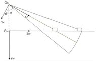
Further, step 3 is to arrange a millimeter wave radar right above the camera H0Where the distance between two sensors is less than 10cm, H0Neglecting, fixing the vehicle at a position with the height H from the ground, setting the inclination angle alpha in the direction vertical to the horizontal plane, recording the residual angle of alpha as theta, and setting the height of the detected vehicle as a fixed value HcarAnd the specific steps of the step 3.1 are as follows:
step 3.1.1: establishing a coordinate system
Step 3.1.1.1: establishing a millimeter wave radar coordinate system Or-XrYr, taking a millimeter wave radar as an origin Or, enabling an Xr axis to be parallel to an optical axis of a camera, enabling a Yr axis to be parallel to a horizontal plane and perpendicular to the Yr axis, and expressing a coordinate value of the Xr in the millimeter wave radar coordinate system by using (Xr, Yr);
step 3.1.1.2: establishing a camera coordinate system Oc-XcYcZc, taking the optical center as a coordinate origin Oc, and respectively enabling an Xc axis and a Yc axis to be parallel to two vertical sides of an image plane, wherein the optical axis of the camera is a Zc axis, and coordinate values of the Xc axis, the Yc axis and the Yc axis in the camera coordinate system are expressed by (Xc, Yc, Zc);
step 3.1.1.3: establishing a world coordinate system Ow-XwYwZw, taking an intersection point which passes through the camera equipment and is vertical to the horizontal ground as Ow, wherein Yw is vertical to the horizontal plane, Xw is positioned on the horizontal plane and is parallel to an Xc axis of the camera coordinate system, Zw is positioned on the horizontal plane and is parallel to a Yc axis of the camera coordinate system, and coordinate values of the ww and the XwYwZw in the world coordinate system are expressed by (Xw, Yw, Zw);
step 3.1.1.4: establishing an image coordinate system Oi-XY, taking the center of an image plane as a coordinate origin Oi, and respectively representing the coordinate values of two vertical sides of the image plane by (X, Y) with the X axis and the Y axis parallel to the image plane;
step 3.1.1.5: establishing a pixel coordinate system O-UV, taking the vertex at the upper left corner of the image plane as an origin O, and expressing coordinate values of a U axis and a V axis which are respectively parallel to two vertical edges of the image plane by using (U, V), wherein the pixel coordinate system is the image coordinate system taking a pixel as a unit;
step 3.1.2: coordinate transformation
Step 3.1.2.1: converting a world coordinate system into a camera coordinate system, wherein the specific formula is as follows:
wherein, R is an orthogonal identity matrix of 3 multiplied by 3 and describes a rotation relation, and T is a three-dimensional translation vector and describes a translation relation; o isTBeing three-dimensional zero vectors, i.e. OT=[0 0 0];
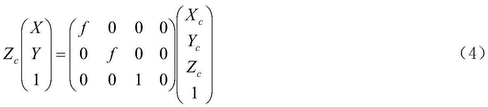
Step 3.1.2.2: the camera coordinate system is converted into an image coordinate system, and the specific formula is as follows:
wherein f is the focal length of the camera;
step 3.1.2.3: converting an image coordinate system into a pixel coordinate system, wherein the specific formula is as follows:
wherein A is an internal reference matrix obtained by a Zhang Zhengyou camera calibration method;
step 3.1.2.4: converting the radar coordinate system into a world coordinate system, wherein the specific formula is as follows:
step 3.1.2.5: the millimeter wave radar coordinates are converted into pixel coordinates, and the conversion relationship is derived as follows according to the formula (1) to the formula (6):
further, the coordinate-corrected object includes: the depression angle of the camera, the projection center point of the camera, the frame width and the frame height of the image sequence, and the pixel coordinates of the corrected motor vehicle are obtained.
Further, in the step 3.2, a yolo network model is adopted to train the paddley frame to obtain a vehicle detection model, and the vehicle detection model provides the pixel prediction frame coordinates of the vehicle.
Further, the time matching of step 4 specifically comprises the following steps:
step 4.1.1: setting the sampling frequency of a millimeter wave radar and the sampling frequency of a camera, wherein the sampling frequency of the millimeter wave radar is greater than the sampling frequency of the camera;
step 4.1.2: and taking the time of the millimeter wave radar as a reference, acquiring time data of two frames of images before and after the time of the millimeter wave radar, comparing the difference value of the time information of the radar data and the time information of the two frames of images, and keeping the image data with smaller difference value.
Further, the spatial matching and data fusion in step 4 specifically comprises the following steps: and comparing the pixel coordinates after the coordinate conversion with a vehicle pixel prediction frame provided by a vehicle prediction model, if the pixel coordinates after the coordinate conversion are contained in the prediction frame, judging that the pixel coordinates are the same vehicle information, and performing data fusion, wherein the data fusion displays the matched data on a picture together by utilizing an OpenCV library function.
The invention has the beneficial effects that: the millimeter wave radar and the high-angle camera are used for acquiring data, the millimeter wave radar data and the image data are fused through coordinate conversion and time-space data matching, and the vehicle detection model is trained through the fused data, so that the sensitivity and the accuracy of the vehicle detection model are improved; the high visual angle acquisition is different from the head-up visual angle, the selection of the world coordinate system is suitable for the detection of the motor vehicle with the high visual angle, the coordinate conversion is accurate, and the error is small; the advantages of radar and video data are combined, the stability is high, the influence of environmental factors such as weather light is small, and the anti-interference capability is strong.
Drawings
Figure 1 is a schematic flow diagram of the data acquisition and processing method of the present invention,
FIG. 2 is a schematic perspective view of the millimeter wave radar coordinate system, camera coordinate system and world coordinate system of the present invention,
figure 3 is a side view of the camera coordinate system and world coordinate system of the present invention,
figure 4 is a top view of the world coordinate system of the present invention,
FIG. 5 is a schematic diagram of the relationship of the millimeter wave radar coordinate system, the camera coordinate system and the image coordinate system of the present invention,
figure 6 is a schematic diagram of the relationship of the image coordinate system and the pixel coordinate system of the present invention,
fig. 7 is a graph of the test effect of the present invention.
Detailed Description
The present invention is further illustrated by the following figures and specific examples, which are to be understood as illustrative only and not as limiting the scope of the invention, which is to be given the full breadth of the appended claims and any and all equivalent modifications thereof which may occur to those skilled in the art upon reading the present specification.
As shown in fig. 1, the coordinate transformation matching vehicle detection method based on millimeter wave radar and video data of the present invention includes the following steps:
step 1: the millimeter wave radar acquires detection data, wherein the detection data comprises the linear distance, the angle information and the radial speed of the motor vehicle and the millimeter wave radar and the time information of each frame of radar data;
step 2: a high-angle camera collects video data;
and step 3: data processing, converting and correcting the coordinate data
Step 3.1: the millimeter wave radar coordinates of the vehicle are converted into pixel coordinates of the vehicle in the image, and the millimeter wave radar coordinates cannot be directly converted into the pixel coordinates, so that the millimeter wave radar coordinates are indirectly converted into the pixel coordinates by converting the millimeter wave radar into a world coordinate system.
Step 3.1.1: establishing a coordinate system
Step 3.1.1.1: as shown in fig. 2, a millimeter wave radar coordinate system Or-XrYr is established with the millimeter wave radar as an origin, an Xr axis is parallel to an optical axis of the camera, a Yr axis is parallel to a horizontal plane and perpendicular to the Yr axis, and a coordinate value in the millimeter wave radar coordinate system is represented by (Xr, Yr);
step 3.1.1.2: establishing a camera coordinate system Oc-XcYcZc, taking the optical center as a coordinate origin Oc, and respectively enabling an Xc axis and a Yc axis to be parallel to two vertical sides of an image plane, wherein the optical axis of the camera is a Zc axis, and coordinate values of the Xc axis, the Yc axis and the Yc axis in the camera coordinate system are expressed by (Xc, Yc, Zc);
step 3.1.1.3: establishing a world coordinate system Ow-XwYwZw, wherein the top view of the world coordinate system is shown in fig. 4, the intersection point of the world coordinate system Ow and the camera equipment perpendicular to the horizontal ground is Ow, Yw is perpendicular to the horizontal plane, Xw is positioned on the horizontal plane and is parallel to the Xc axis of the camera coordinate system, Zw is positioned on the horizontal plane and is parallel to the Yc axis of the camera coordinate system, the coordinate values of the ww and the xwyw in the world coordinate system are represented by (Xw, Yw, Zw), and the side view of the camera coordinate system and the world coordinate system is shown in fig. 3;
step 3.1.1.4: establishing an image coordinate system Oi-XY, taking the center of an image plane as a coordinate origin Oi, and respectively enabling an X axis and a Y axis to be parallel to two vertical edges of the image plane, and expressing coordinate values of the X axis and the Y axis by using (X, Y), wherein the relationship among a millimeter wave radar coordinate system, a camera coordinate system and the image coordinate system is shown in FIG. 5;
step 3.1.1.5: establishing a pixel coordinate system O-UV, taking the vertex at the upper left corner of the image plane as an origin O, and using (U, V) to represent the coordinate values of the U axis and the V axis which are respectively parallel to two vertical edges of the image plane, wherein the pixel coordinate system is the image coordinate system taking the pixel as a unit, and the relationship between the image coordinate system and the pixel coordinate system is shown in FIG. 6;
step 3.1.2: coordinate transformation
Step 3.1.2.1: converting a world coordinate system into a camera coordinate system, wherein the specific formula is as follows:
wherein, R is an orthogonal identity matrix of 3 multiplied by 3 and describes a rotation relation, and T is a three-dimensional translation vector and describes a translation relation; o isTBeing three-dimensional zero vectors, i.e. OT=[0 0 0];
Step 3.1.2.2: the camera coordinate system is converted into an image coordinate system, and the specific formula is as follows:
wherein f is the focal length of the camera;
step 3.1.2.3: converting an image coordinate system into a pixel coordinate system, wherein the specific formula is as follows:
wherein A is an internal reference matrix obtained by a Zhang Zhengyou camera calibration method;
step 3.1.2.4: converting the radar coordinate system into a world coordinate system, wherein the specific formula is as follows:
step 3.1.2.5: converting the millimeter wave radar coordinates into pixel coordinates, and according to the formulas (1) to (6), deducing the conversion relation between the millimeter wave radar coordinates and the pixel coordinates as follows:
step 3.2: inputting video data to the trained vehicle detection model to directly obtain pixel coordinates of the motor vehicle;
step 3.3: carrying out coordinate correction according to the actual installation angles of the millimeter wave radar and the high-angle camera;
and 4, step 4: data matching and fusion
Step 4.1: and performing time matching on the vehicle pixel coordinates converted by the millimeter wave radar coordinates and the pixel coordinates obtained by the video data through a vehicle detection model: setting the sampling frequency of a millimeter wave radar and the sampling frequency of a camera, wherein the sampling frequency of the millimeter wave radar is greater than the sampling frequency of the camera; setting the sampling frequency of a millimeter wave radar as 80hz and the sampling frequency of a camera as 30fps, namely, the sampling interval time of radar data is about 83.33ms, and each second is about 12 frames; the sampling interval of the camera is about 33.33ms, 30 frames per second, the time data of two frames of images before and after the time of the millimeter wave radar is obtained by taking the time of the millimeter wave radar as a reference, the difference value of the time information of the radar data and the time information of the two frames of images is compared, and the image data with the smaller difference value is reserved;
step 4.2: carrying out spatial matching on the pixel coordinates of the vehicle converted by the millimeter wave radar coordinates and the pixel coordinates of the video data obtained by the vehicle detection model: comparing the pixel coordinates after coordinate conversion with a vehicle pixel prediction frame provided by a vehicle prediction model, if the pixel coordinates after coordinate conversion are contained in the prediction frame, judging that the pixel coordinates are the same vehicle information, and performing space matching;
step 4.3: carrying out data fusion on the data which is successfully matched in time and space;
and 5: and (3) storage and display of fusion data: and storing the final successful matching result, outputting the image after data fusion is completed, and displaying the matched data on the picture by using the OpenCV library function, as shown in fig. 7, which is a test effect diagram of the embodiment.
In light of the foregoing description of the preferred embodiment of the present invention, many modifications and variations will be apparent to those skilled in the art without departing from the spirit and scope of the invention. The technical scope of the present invention is not limited to the content of the specification, and must be determined according to the scope of the claims.